
DMP808D - Audio Mixer PHONIC - Free user manual and instructions
Find the device manual for free DMP808D PHONIC in PDF.


| Product Type | Digital Matrix Processor and Automatic Mixer |
| Input Channels | 8 balanced Euroblock + 4 unbalanced RCA (12 total) |
| Output Channels | 8 balanced Euroblock |
| Matrix Mixing | 8 x 8 full matrix |
| Processor | 40-bit floating point |
| Sampling Rate | 44.1 kHz / 48 kHz, selectable |
| Control Interface | Ethernet (10/100 Mbps) with Windows software |
| Equalizers | 4-band parametric + 31-band graphic |
| Dynamic Processors | Compressor, limiter, noise gate, expander, ducker |
| Automatic Functions | Auto level control (ALC), automixer, feedback silencer |
| Delay | Adjustable up to 680 ms (input/output) |
| Dante Option (DMP808D only) | Built-in Dante expansion for multi-channel network audio |
| Power Supply | 120/240 VAC switching, 15 A Edison cable; +24 VDC external |
| Dimensions (H x W x D) | 44 x 484 x 295 mm (1.7 x 19 x 11.6 in) |
| Weight | 4.2 kg (9.3 lbs) |
| Mounting | Standard 19-inch rack, 1U |
| Front Panel Controls | Gain knobs per input, power switch, status LEDs |
| Safety Compliance | Professional use, follow instructions; do not expose to moisture |
| Cleaning | Use only a dry cloth |
| Spare Parts & Repairability | No user-serviceable parts; refer servicing to qualified personnel |
Frequently Asked Questions - DMP808D PHONIC
User questions about DMP808D PHONIC
0 question about this device. Answer the ones you know or ask your own.
Ask a new question about this device
Download the instructions for your Audio Mixer in PDF format for free! Find your manual DMP808D - PHONIC and take your electronic device back in hand. On this page are published all the documents necessary for the use of your device. DMP808D by PHONIC.
USER MANUAL DMP808D PHONIC
IMPORTANT SAFETY INSTRUCTIONS....1
INTRODUCTION....2
FEATURES....2
GETTING STARTED 2
GLOSSARY 3
CONTROLS & SETTINGS 4
DIP SWITCH SETTINGS 6
DANTE CONNECTIVITY (DMP808D ONLY)....6
GENERAL SETTINGS 7
HOW TO SET THE SYSTEM IP ADDRESS 8
CONTROL SOFTWARE....9
SIGNAL PROCESSORS 22
TROUBLESHOOTING 23
SPECIFICATIONS....24
PARAMETERS....25
IMPORTANT SAFETY INSTRUCTIONS
-
Read these instructions – All the safety and operating instructions should be read before this product is operated.
-
Keep these instructions – The safety and operating instructions should be retained for future reference.
-
Heed all warnings – All warnings on the appliance and in the operating instructions should be adhered to.
-
Follow all instructions – All operating and use instructions should be followed.
-
Do not use this apparatus near water – The appliance should not be used near water or moisture – for example, in a wet basement or near a swimming pool, and the like.
-
Clean only with dry cloth.
-
Do not block any ventilation openings. Install in accordance with the manufacture's instructions.
-
Do not install near any heat sources such as radiators, heat registers, stoves, or other apparatus (including amplifiers) that produce heat.
-
Do not defeat the safety purpose of the polarized or grounding plug. A polarized plug has two blades with one wider than the other. A grounding plug has two blades and a third grounding prong. The wide blade or the third prong is provided for your safety. If the provided plug does not fit into your outlet, consult an electrician for replacement of the obsolete outlet.
-
Protect the power cord from being walked on or pinched particularly at the plugs, convenience receptacles, and at the point where they exit from the apparatus.
-
Only use attachments/accessories specified by the manufacturer.
-
Use only with the cart, stand, tripod, bracket, or table specified by the manufacturer, or sold with the apparatus. When a cart or rack is used, use caution when moving the cart/apparatus combination to avoid injury from tip-over.
-
Unplug the apparatus during lightning storms or when unused for long periods of time.
-
Refer all servicing to qualified personnel. Servicing is required when the apparatus has been damaged in any way, such as power supply cord or plug is damaged, liquid has been spilled or objects have fallen into the apparatus has been exposed to rain or moisture, does not operate normally, or has been dropped.
-
CAUTION: These servicing instructions are for use by qualified service personnel only. To reduce the risk of electric shock, do not perform any servicing other than that contained in the operating instructions unless you are qualified to do so.
-
Do not install this equipment in a confined or building-in space such as a book case or similar unit, and remain a well ventilation conditions at open site. The ventilation should not be impeded by covering the ventilation openings with items such as newspaper, table-cloths, curtains, etc.
-
WARNING: The mains plug/appliance coupler is used as disconnect device, the disconnect device shall remain readily operable.
-
This apparatus is for professional use only.

CAUTION: TO REDUCE THE RISK OF ELECTRIC SHOCK, DO NOT REMOVE COVER (BACK).NO USER-SERVICEABLE PARTS INSIDE.REFER SERVICING TO QUALIFIED PERSONNEL.
-
WARNING: To reduce the risk of fire or electric shock, do not expose this apparatus to rain or moisture. The apparatus shall not be exposed to dripping or splashing and that objects filled with liquids, such as vases, shall not be placed on apparatus.
-
This lightning flash with arrowhead symbol within an equilateral triangle is intended to alert the user to the presence of non-insulated "dangerous voltage" within the product's enclosure that may be of sufficient magnitude to constitute a risk of electric shock.
Warning: To reduce the risk of electric shock, do not remove cover (or back) as there are no user-serviceable parts inside. Refer servicing to qualified personnel.
The examination point within an equilateral triangle is intended to alert the user to the presence of important operating and maintenance instructions in the literature accompanying the appliance.
- Protective earthing terminals. The apparatus should be connected to a mains socket outlet with a protective earthing connection.

INTRODUCTION
Congratulations on your purchase of a DMP808 Digital Matrix Processor and Automatic Mixer. The DMP808 provides a simple, effective way to maintain your audio levels in live venues without having to keep on your toes. A single DMP808 offers twelve-in, eight-out support and the entire unit can be controlled remotely through standard potentiometers and remote controls. Internal processing is accomplished through a high quality 40-bit floating point processor, with internal signal processors and matrix routing all handled with ease.
Clear, easy-to-use software on your Windows computer makes control of your onboard processing simple. The software offers full performance monitoring for each processor, giving real-time information on the load placed upon DSPs.
We know how eager you are to get started – hooking up your new DMP808 is probably your first priority right now – but we would advise that you take the time to look over this manual. Inside you'll find important safety considerations and operating instructions that could prove helpful. After reading the manual, we would suggest putting it somewhere easy to find as you will probably need to refer to it later on.
FEATURES
√ 8 input channels and 8 output channels available via 3-pin euroblock connections with 4 additional RCA inputs
√ 8 x 8 matrix mixing
√ 40-bit floating point processor with internal sampling rate selectable between 44.1 and 48 KHz
√ Ethernet connectivity for network control application
√ Automatic DHCP network IP configuration
√ Easy and intuitive control software from Asystems
√ 3 independent user-accounts
√ 4-band parametric EQs and 31-band graphic equalizers
√ Autoleveler (Loudness Control)
√ Compressors and noise gates
√ Level ducking with trigger control
√ All signal processors flexible and user-controllable
√ DMP808D includes the Dante multi-channel network expansion option
GETTING STARTED
For easy control of the DMP808, you will need to connect the device to a network-enabled Windows computer. By installing the Asystems software on a computer will allow for remote control of this unit. Enter the DMP808's IP address into the PC software to locate the DMP808 on either the local area network.
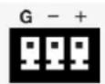
Connect all necessary input and output devices. Input can be achieved through correctly wired euroblock connectors. Wiring for balanced euroblock connectors should be as follows:
Pin 1: Shield/Ground
Pin 2: Cold (−)
Pin 3: Hot (+)
Whereas unbalanced connectors can be wired as so:
Pin 1: Shield/Ground
Pin 2: Link to Pin 1
Pin 3: Hot (+)
GLOSSARY
The following are a few words that may serve you well while reading this manual. These aren't in depth explanations, but should hopefully give you the basics and a place to start.
Balanced Connections - balanced connections offer three conductors, carrying a ground, an in-phase signal, and an out-of-phase signal. Once the two signals are sent from one device to another, the out-of-phase signal has its phase inverted and the two signals are combined. Any interference picked up along the way is removed through to phase cancellation. This allows cables to be run over long distances without collecting excessive noise on the way.
Compressor - a Compressor reduces signals over a user-defined threshold by a user-defined amount/ratio.
Dynamic Processor – is any kind of processor that dynamically – or in real time – adjusts signal properties.
EQ – Equalizer – is a device or process that allows users to boost or attenuate audio signals at specific frequencies.
Euroblock – These types of inputs allow for self-wiring of connections for permanent installations. Check the "Getting Started" section for more information on wiring.
GEQ – Graphic Equalizer – is in essence the same as an equalizer, but this title is reserved for equalizers with more 'bands' than the typical EQ. While a typical channel EQ may only allow for 3 or 4 frequencies to be adjusted, a graphic equalizer may allow for 31 different frequencies.
GUI – Graphical User Interface – this is the remote PC software used for the DMP808.
HPF – High Pass Filter – a high pass filter will cut or significantly reduce all audio signals below a particular user-defined frequency, allowing – as the name suggests – high frequency sounds to pass through.
High Shelf Filter – the high shelf filter will reduce or increase all audio signals below a particular frequency. The level at which the signal is boosted/attenuated is determined by the user.
Limiter - work just as compressors do; however with an input to output signal ratio permanently set to infinity-to-1.
LPF – Low Pass Filter – a low pass filter will cut all audio signals above a particular user-defined frequency, allowing low frequency sounds to pass through. This is significantly useful when using subwoofer speakers on particular outputs.
Low Shelf Filter – the low shelf reduces or increases the level of audio signals below a particular frequency selected by the user. The level at which the signal is altered is also set by the user.
Network – a network is a series or group of computers that are interconnected so as to share information. In the case of the DMP808, the network allows for remote operation of the device using our Windows-based computer.
Noise Gate - a noise gate is a dynamic process that turns off or significantly attenuates the audio signal passing through it when the signal level falls below a user adjustable threshold.
Unbalanced Connections – unlike balanced connections, unbalanced connections only have 2 conductors: one for the signal and one for the grounding. This, unfortunately, makes them more susceptible to noise and interference.
CONTROLS & SETTINGS
FRONT PANEL
1. Mounting Holes
These holes are for mounting the DMP808 on a standard 19" rack.
2. Power Switch
Flick this switch to sturn the unit on or put it on standby. Be aware that the power switch can be disabled through the Asystems DMP808 software.
3. Power LED
This LED indicator will illuminate when the DMP808 is activated – whether by switch or through the remote software.
4. Disable LED
This LED will light up when the power switch is disabled. When this occurs, the DMP808 cannot be turned on or put on standby via the front panel switch. This function is disabled within the Asystems PC software.
5. Output LEDs
The Mix Output LEDs will light up green when an output signal is present on the corresponding output mix. It will also flash red when the output channel clips. In this event, you can reduce any excessive input signals, or turn down your master output mix level through the control software.
6. Signal/Clip LED
This LED indicator is found on every input channel. When a signal is present in the input channel, the LED will light up green. When it clips, it will light up red. In the event that the LED is red, we suggest reducing the input signal level. Occasional flashes may be acceptable if it doesn't affect your program material.
7. Gain Controls
These rotary controls will allow users to adjust the final input level for channels 1 through 8.

REAR PANEL
8. Ethernet Connection
This connection is for standard RJ-45 cables, used for 10/100 Ethernet control. Using a CAT5 twisted pair copper cable, Asystems doesn't recommend a distance of more than 100 meters to the nearest computer or hub. The Ethernet connection is used to control the software via the PC control software.
9. Peripheral Ethernet Connection
The Ethernet connection marked Peripheral is for connecting Asystems remote peripherals. This will allow for remote control of various internal functions.
10. Euroblock Line Inputs
The DMP808 offers a total of eight line input channels. These inputs are active balanced with euroblock connectors If an unbalanced signal is used, Asystems advises that customers ground the unused conductor.
11. Euroblock Line Outputs
The DMP808 offers a total of eight euroblock line outputs. These are servo-balanced euroblock connectors and can be wired to either balanced or unbalanced connections.
12. RCA Inputs
These unbalanced RCA connectors are for the connection of stereo RCA cables. These act as inputs 9 to 12, as found in the "Ex In" pages within the DMP808 software.
13. Unit ID Controls & DIP Switch
The Unit ID controls consist of a single rotary switch as well as 8-pin DIP switch. These essentially adjust various controls and settings as well as assisting in things such as firmware updates. More information on Unit ID settings can be found in the relevant area of this manual. These controls extend to IP address settings and initialization.
14. 24VDC Input
This connector is used for emergency power to the DMP808. This input connector can be used with a 24VDC battery or power supply to ensure operation continues in the event of power outage.
15. GPIO IN
These euroblock connectors can be wired to connect the Asystems RM-4 for remote control.
16. GPIO OUT
When connected, it provides 0V or 5V of power for external controller to turn the unit on or put it on standby.
17. Digital I/O Expansion Slot
This slot is for the addition of the I/O networking expansion card for extending the channel count of the DMP808. The DMP808 can act as a networking portal to our other audio networking devices, including the DMA digital matrix amplifiers.
18. AC Power Connector
This is for a standard IEC power cable.

DMP808 DIP SWITCH SETTINGS


| PIN FUNCTION POSITION DESCRIPTION | |||
| 1 Firmware Upgrade | ON Firmware Upgrade Mode | ||
| OFF Operation Mode | |||
| 2 IP address setting method | ON By Hardware | ||
| OFF By Software | |||
| 3 Leading digit of host digit of IP address | ON | Please consult “How to Set Unit IP” section of this manual. | |
| OFF | |||
| 4 Second digit of host digit of IP address | ON | ||
| OFF | |||
| 6 Enable/Disable Panel VR | ON Panel | VR Enabled | |
| OFF Panel | VR Disabled | ||
| 7 Resume factory default settings | ON Resume factory default settings | ||
| OFF Operation Mode | |||
DANTE CONNECTIVITY [DMP808D ONLY]
The Dante expansion card should come pre-installed with the DMP808D (and is not included with the DMP808). This is an optional component that is not included on all versions of the DMP808.
The "Primary" port on the Dante card can be connected to your network router. The Secondary port can be connected to the Primary port of additional units. Alternatively, all units can be connected to the router using their "Primary" ports.
The Audinate Dante Controller can be downloaded through their website (www.audinate.com). This is used to route the network signals from numerous Dante-enabled devices. Each device will show up as its own independent signal with input and output channels listed. All units will be automatically discovered by the software.
Signals can be routed internally using the instructions found in section 5. The actual network input signals received by your DMP808s are determined by the aforementioned Dante Controller software. It should be noted that each Network input mix can only have a single source assigned to it.
Connecting additional units to your network will automatically be recognized by the software, allowing any of these systems to have their signals routed throughout the network.
In addition to the regular network routing of signals, the Dante expansion cards are compatible with Audinate's

Virtual Soundcard software which allows for recording of audio to the computer and playback of audio from the computer. At the time of publication, this a permanent license for this software is available for \$29.99. The controller software is completely free on Windows 7 (SP1), Windows 8.1, Windows 10, OSX 10.10.5 (Yosemite), OSX 10.11.6 (El Capitan) and macOS 10.12 (Sierra).
GENERAL SETTINGS
RESTORE FACTORY SETTINGS

- Unplug the DMP808's power cable.
- Switch POLE 7 on the rear panel DIP Switches to the ON position.
- Replace the power cable and power on the DMP808. Wait for the start up procedure to complete.
- Switch POLE 7 to OFF.
- Now your DMP808 is restored to the factory default settings.
NOTE: A factory restore is particularly helpful in the event that user names and passwords are forgotten. Restoring to factory default settings will restore user names back to default values.
ACTIVATING VR CONTROLS
Use pole 6 on the rear panel DIP switch to turn the front panel controls on and off. When OFF, the rotary volume controls on the front of the DMP808 will be deactivated. In the event that controls are not functioning, be sure to check this before taking further action.

In addition to this switch, each and every individual control can be deactivated within the software. Within the Control Panel page, the ON/OFF buttons at the very bottom of each channel will allow you to turn the front panel rotary controls on and off.
FIRMWARE UPDATE
When performing a firmware update, a few steps need to be followed. First of all, set the first pole of the DIP switch to the upper-most position.

A connection needs to be established between the DMP808 system and the Windows remote software. After this is done, enter the Global Settings tab and the Utility menu. At the very bottom of the page, click the "Update" button under the Firmware section. Users will be prompted to select the firmware file (available on the Asystems website) and the firmware update process will begin.
HOW TO SET THE SYSTEM IP ADDRESS
Connecting the DMP808 to a computer for remote operation requires the user to enter an IP address for the unit. There are two controls that help determined the IP address of the DMP808 matrix processor. The first is the UNIT ID rotary control, that lets you select 0 – 9 and A – F. The second is the DIP switch located directly beside the rotary switch. The 3rd and 4th poles of the DIP switch can be used to set a numerical value between 0 and 3. These combine with the UNIT ID rotary switch to form a hexadecimal value for the last value of the IP address (as indicated below).

Value The 3rd PIN The 4th PIN
0 OFF OFF
1 ON OFF
2 OFF ON
3 ON ON
The configurable range for the last digit is 0, 1, 2, 3, 4, 5, 6, 7, 8, 9, A, B, C, D, E and F.
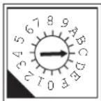
The unit ID configuration mechanism of DMP808 is developed based on "hexadecimal numeral system". Therefore, a scientific calculator may be required when setting the unit ID of the IP address for DMP808. Below is the procedure for setting the unit ID:
- Define the IP address for your DMP808.
- Convert the decimal value of the host bits of the IP address to a Hexadecimal value (consult the provided table).
- Set PINS 3 and 4 on the 8-PIN DIP switch according to the first digit of the converted Hexadecimal value.
- Set the rotary switch according to the second digit of the converted Hexadecimal value.
Example: To set an IP address of "192.168.0.21" on your DMP808, the rotary control should be set to 5 and the DIP switches 3 and 4 should be set to ON and OFF, respectively. This sets a hexadecimal value of 15, which - converted to decimal - is 21. Consult the included chart for hexadecimal to decimal conversion.
Hexadecimal to Decimal Conversion
| HEX DEC HEX DEC HEX DEC HEX DEC HEX DEC | |||||||||
| 01 1 0E | 14 1B 27 28 | 40 35 53 | |||||||
| 02 2 0F | 15 1C 28 29 | 41 36 54 | |||||||
| 03 3 10 | 16 1D 29 3A | 42 37 55 | |||||||
| 04 4 11 | 17 1E 30 2B | 43 38 56 | |||||||
| 05 5 12 | 18 1F 31 2C | 44 39 57 | |||||||
| 06 6 13 | 19 20 32 2D | 45 3A 58 | |||||||
| 07 7 14 | 20 21 33 2E | 46 3B 59 | |||||||
| 08 8 15 | 21 22 34 2F | 47 3C 60 | |||||||
| 09 9 16 | 22 23 35 30 | 48 3D 61 | |||||||
| 0A 10 1 | 7 23 24 36 | 81 49 3E 62 | |||||||
| 0B 11 18 | 24 25 37 | 32 50 3F 63 | |||||||
| 0C 12 1 | 9 25 26 38 | 33 51 | |||||||
| 0D 13 1 | A 26 27 39 | 34 52 | |||||||
DMP808 CONTROL SOFTWARE
CONNECTION
After a connection is established, you can use the control software to remotely control and change the settings of your DMP808. To begin, please visit the Asystems website to download the control software program. The program will be downloaded to a zipped folder. Please unzip the folder then follow the instructions to proceed the installation.
- Turn on your DMP808.

- Connect your computer to the DMP808 using any commercially available CAT5 RJ-45 Ethernet cable.
![graph TD A["Router Port 1"] --> B["USB Cable"] B --> C["USB Cable Interface"] C --> D["USB Cable Interface"] D --> E["Laptop"] E --> F["USB Cable Interface"] F --> G["USB Cable Interface"] G --> H["USB Cable Interface"] H --> I["USB Cable Interface"] I --> J["USB Cable Interface"] J --> K["USB Cable…](/content/2026/05/1083949/images/944a3e2f9d431f6bf3d7beb3a9464852a5a00c5826a22ab3315f8b4cc3063564.jpg)
- On the rear panel, set PIN 2 of the DIP switch to ON.

- Set PIN 3 and 4 of the DIP switch to OFF.

- Set the UNIT ID rotary to 1. This will set the DMP808's internal IP address to 192.168.0.1.

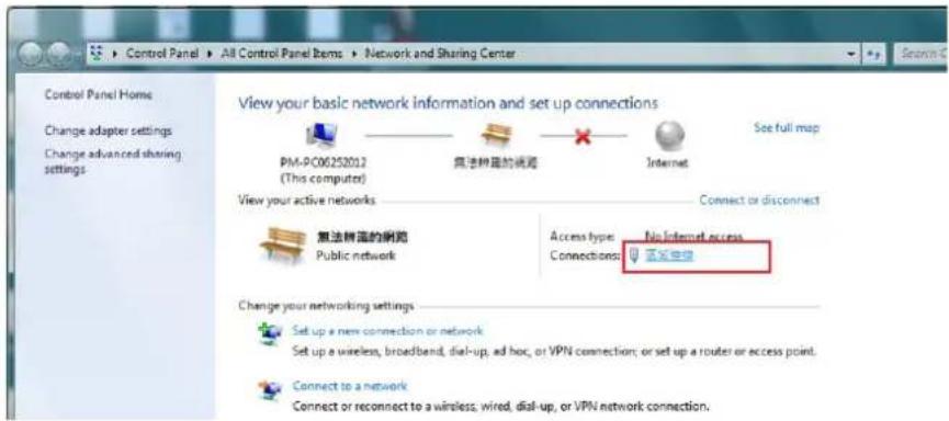
- Go to the "Open Network and Sharing Center" of your computer.

- Click on "Connections".
- Select


- Select "Internet Protocol Version 4 (TCP/IPv4)" and click on Properties

- Please make a note of the current settings for future reference.

- Change the IP Address to "192.168.0.3" (or any other compatible IP address) and click "OK".

- Select the executable file (.exe) inside the DMP808 Control Software folder.
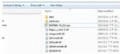
- On login page, enter the following information.
IP Address: 192.168.0.1
User Name: USER_1
Password: ASYSTEMS
NOTE: In the event that you forget the user name and/or password that you had previously set, please enter the following information to retrieve them.
User Name: Admin
Password: ASYSTEMS
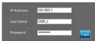
- Click Login to begin the installation.
If your DMP808 and your computer are connected through an existing local area network and not a set IP address, please follow the steps below to establish a connection.
-
Make sure that your DMP808 and computer have successfully connected to the local area network.
-
Select the executable file (.exe) inside the DMP808 Control Software folder.

- Select Scan at the login screen to search the current IP address.
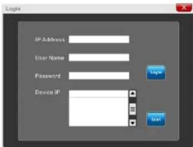
- All the existing IP addresses will appear in the "Device IP" drop-down box.

-
Select the IP address that will be used for DMP808.
-
Enter the following information on the login page.
User Name: USER_1
Password: ASYSTEMS
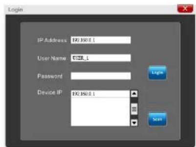
- Click Login to begin the installation.
DSP
The DSP page will give you an overall idea of input and output mixes (including levels and naming) as well as offer a manner to view and edit the current signal processors assigned to input and output channels.
Name: Edit the name for each of the individual input channels.
On/Off: Use this button to switch the corresponding input channel on and off.
Processing: These buttons allow you to inject any of the DMP808's internal signal processors right into the input chain. Processing will be accomplished in order from left to right. For more information on the available programs, check the Signal Processor section of this manual
Reset Button: Pushing these buttons will reset the DSP parameters for the input or output, including name, on/off
status, and selected signal processors. There is a reset button available for each the input and output.
![graph TD A["Channel In"] --> B["Ch1"] A --> C["Ch2"] A --> D["Ch3"] A --> E["Ch4"] A --> F["Ch5"] A --> G["Ch6"] A --> H["Ch7"] A --> I["Ch8"] B --> J["Mix In"] C --> K["Mix In"] D --> L["Mix In"] E --> M["Mix In"] F --> N["Mix In"] G --> O["Mix In"] H --> P["Mix In"] I --> Q["Mix In"] J --> R["Chan…](/content/2026/05/1083949/images/eab36d62e7a554c62933c501618969d69218cd80a2aa61323c2757eff7ad5f76.jpg)
Monitoring: The DMP808 software offers extensive monitoring for DSP performance. The percentage of the processor used will be visible at the bottom of the page.
Channel In Matrix
This page offers matrix mixing for the Analog inputs to the Channel Input mixes. Any of the input sources can be assigned to the individual “Channel Input” mixes.
Each of the possible input matrix sources can have a number of controls available. These include:
Attenuation/Fader: Adjust the input level of each of the individual signals.
Panning: These will let you adjust the left/right mix of the incoming signals.
ALC: This button will assign the DMP808's Auto Level Control to the corresponding input signal.
Duck: Pushing this button will apply the ducking feature to the corresponding input signals. The duck function can be activated as ducker 1, ducker 2, or off, the settings of which are decided by their respective menus.
INV: This button will invert the phase of the corresponding signal.

On: This button allows you to turn the corresponding input signal on and off. When turned off, the signal will not be sent to the Input Channels selected.
Routing: Each of the 12 analog inputs can be assigned to the DMP808's 8 matrix channels. These input channels are what will be used for the DSP processing and will be then routed to your output mix.
Mix Matrix
Each of the 8 Mix Ins and the 8 Mix Outs can be tweaked before being sent to the main outputs.
Attenuation/Fader: Adjust the input level of each of the individual input signals or matrix mixes.
Auto Mixer: This button on each channel will activate automixing on the corresponding channel. When deactivated, the channel is set to manual mode and will work independently to the automixer function. When set to Auto, 'auto' channels will compensate for changes in levels to adhere to the selected 'target level' (see "SEL").
Auto Mixer Response Time: The time to automixer takes to activate can be selected using the pull-down menu to the left of the 'Auto' buttons.
SEL: The select button on each Mix Out will allow the user to use the selected channel's output level as the target level for the automixer function.

INV: This button will invert the phase of the corresponding input or matrix signal.
On: This button allows you to turn the corresponding input / output signal on and off. When an input is turned off, the signal will not be sent to any of the matrix outputs selected. Turning off a Mix Out will effectively disable that output.
Routing: Each of the analog inputs and matrix inputs can be assigned to the DMP808's output mix.
Clear: The 'CLEAR' button to the left of the routing section will allow users to instantly clear all routing selections.
Link: The 'LINK' pull-down menu allows users to assign the corresponding channel to a particular group. Linking two or more mixes in a single group will link the automixer parameters of those particular mixes.
Signal Generator
The Channel Inputs and Matrix Output can have a signal generator applied to them. The option can be found in the Channel Matrix and Mix Matrix pages by right clicking the mouse. The signal generator can be activated with the "ON" buttons and assigned to the appropriate mixes using the matrix/channel select section below the controls.
There are 4 different signals available, including White Noise and Pink Noise – ideal for setup of systems – and sine and sweep waves – for testing of equipment and for general setup purposes.
Sine: The sine wave can be selected between 20 Hz and 20 kHz. The signal level can also be adjusted, and the signal can be turned on and off.
Sweep: When using the sweep wave, a lowest and highest frequency can be selected. The sweep wave will move between these frequencies and small increments.
The hold time for each frequency can be selected by the
users. There are also controls for adjusting the signal level and turning the sweep wave on and off.
Pink Noise: The pink noise function includes level controls and on/off button.
White Noise: Like the pink noise, the white noise only offers level controls and an on/off button.

Network Matrix
Any of the incoming input signals can be assigned directly to the Network output mixes. The network matrix pages are only used when the Asystems network expansion card is installed in the DMP808. Attenuation: Adjust the input level of each of the individual input and output mixes.
Panning: These will let you adjust the left/right mix of the available mixes.
ALC: This button will assign the DMP808's Auto Level Control to the corresponding input.
Duck: Pushing this button will apply the ducking feature to the corresponding mix. The duck function can be activated as ducker 1, ducker 2, or off, the settings of which are decided by their respective menus.
INV: This button will invert the phase of the corresponding input or matrix signal.
On: This button allows you to turn the corresponding input signal on and off. When turned off, the signal will not be sent to any of the matrix outputs selected.

Routing: Each of the 12 analog inputs, 8 matrix inputs and 8 matrix outputs can be assigned to the DMP808's 8 network outputs. These channels will appear as Network Input connections in any networked Asystems DMP, DMA or NT series devices.
Control Panel
The control panel menu offers complete control of output channels. This menu includes level, gain controls, metering, and a host of other parameters that can be edited.
Channel Name: A preselected channel name can be viewed or edited in this screen.
Fader: The input level can be adjusted using this onscreen fader.
Meters: The input and output signal level of the channel can be viewed through these meters. They can be adjusted between pre- and post-fader meters.
Gain Reduction: The gain reduction meter will provide a real-time indication of any reduction in gain applied by the internal DSP processes of the DMP808 (including compressors-limiters, equalizers, etcetera).
Limiter: This button will activate the internal limiter function for the corresponding channel.

Duck: Activate the 'ducking' feature by pushing this button. The duck function can be activated as ducker 1, ducker 2, or off, the settings of which are decided by their respective menus.
INV: This button will invert the phase of the corresponding signal.
CH ON: This button will turn the corresponding channel on and off.
Network
When using the DMP808 remote software – either within the local area network or through the internet – the network settings need to be set appropriately to allow external computers to identify and connect to it.
The IP address of DMP808 can be set via the system hardware (rear panel) or the software (remote control software).

Set via System Hardware
When the IP address is set via the hardware, the on screen display will show the following:
Device Name: The name of the current device is found here, and it can be adjusted by the user, if necessary.
IP Address: The actual IP address of DMP808 will automatically be detected and shown here. User can manually adjust the IP address through the rear panel.

Set via Software
Device Name: The name of the current device is found here, and it can be adjusted by the user, if necessary.
IP Address: The actual IP address of DMP808 will automatically be detected and shown here. User can manually adjust the IP address through the rear panel.
Security
This tab can be found under the Network Settings menu. The security tab provides a means of securing the DMP808 against unauthorized changes. Through the DMP808's onboard software these accounts can be created for use of the Asystems remote software.

Global Settings
Analog In
Each of the analog inputs can have +48V of phantom power applied to it, ideal for condenser microphones. This menu also allows the user to trim the signal slightly if levels are too excessive. A high-pass filter can also be added to each of the analog inputs to help remove stage rumble and other unwanted noise.

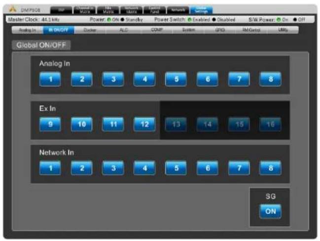
Global In On/Off
This menu provides buttons for each individual input, including analog input, network input, EX IN input and signal generator.
Ducker
The ducker allows a signal to temporarily attenuate below another signal when said signal activates the ducking feature. This is useful when making announcements and other such times when a signal needs to be heard clearly. The ducker can be activated on input and output channels by pushing the 'Duck' buttons found in the individual Matrix control pages. There are two of these 'duckers' total on the DMP808.
Source: This is used to select the source of the duck function; ie. the trigger signal. When the selected source's signal rises to a user-selected level, the currently selected 'duck' signals will attenuate at the selected level.
Threshold: This determines the level that the source signal needs to be before the ducking function will be activated.
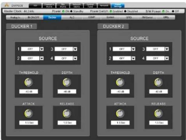
Depth: This determines how much the selected 'duck' signals will be attenuated.
Attack: The attack time is the time it takes for the ducking feature to kick in after the source signal passes the selected threshold.
Release: The release time control will determine the time the 'duck' feature will remain active as the source signal drops back below the set threshold.
ALC – Auto Level Control
An autoleveler will allow users to dynamically change the level of an input or output signal to match a predefined
level set by the user. The autolevel function can be activated for each individual mix in the matrix pages. The settings for these autolevelers can be found within this ALC menu.
In Target: The target level setting allows users to select the desired signal level for their autoleveler. All signals that are processed by the autoleveler will essentially aim for the target level.
Below Target: The below target threshold of the autoleveler is the point at which the autoleveler will kick in. Signals below the threshold will not be affected, but signals above will be have their gain increased.
Ratio: The ratio is the input level change in decibels to the output level change in decibels.
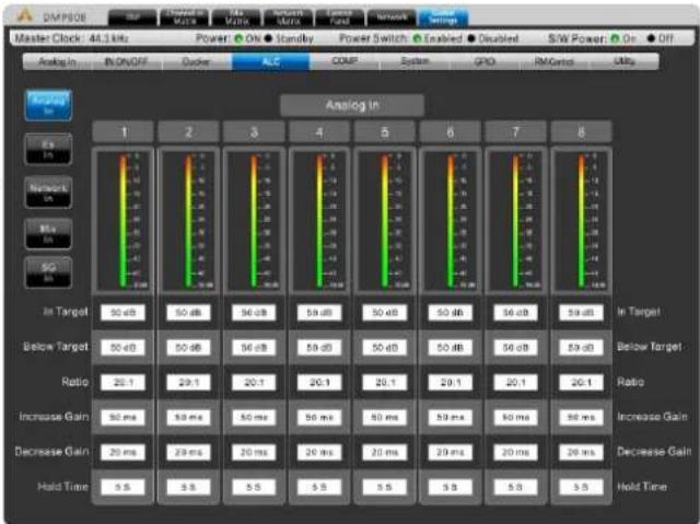
Increase Gain: The increase gain determines the amount that the signal can be increased to meet the target level. This helps prevent sudden, alarming changes in audio level.
Decrease Gain: The decrease gain works the same as the decrease gain, but in reverse. It determines the amount a signal can be cut.
Hold Time: This determines the time the ALC will remain engaged after the signal falls back below the determined threshold.
Compressor/Limiter
This menu allows compressors and limiters to be applied to the channel output
Limiter Threshold: This control determines the threshold for the limiter function. This means that no signal will surpass the selected threshold, being 'compressed' at a ratio of infinity:1.
Compressor Threshold: Use this control to set the threshold of the compressor function. Any signals that surpass the selected threshold will be compressed at the selected ratio.
Compressor Ratio: This control can be used to set the ratio for the compressor. The ratio is expressed as :
Compressor Attack: This control adjusts the attack time of the compressor, essentially determining the time taken for the compressor to kick in after it passes the selected threshold.

Compressor Release: The release control determines the time the DMP808 will wait before disengaging the compressor when the signal bypasses the selected threshold.
Side Chain HPF: This allows users to set a high pass filter on these channels to essentially help rid these channels of low-frequency noise.
System
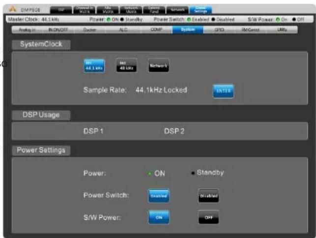
System Clock: This menu allows you to select the internal sampling rate of the DMP808. Users are able to select between either 44.1 or 48 kHz. You can also choose to take clock settings from the audio networking feature. The ENTER button must be pushed to confirm.
Power Settings: There are three power settings on the DMP808. The software power can be turned on and off, essentially enabling the DMP808 to be turned on and off via the software – including event scheduling. The hardware power can be selected on and off, essentially allow the unit to be activated and deactivated using the hardwired switch on the front of the DMP808.
Relay I/O (GPIO)
The general purpose interface output is used to remotely control the DMP808. When properly setup, you can turn the power on or put the system in standby mode.

RM Control
This page offers a number of assignment options for the optional Asystems RM remote controls. More details can be found on the following pages.
Utility
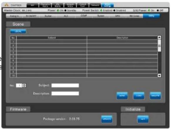
All of the DSP processes can have their settings saved, while there are a number of factory presets available, users are always encouraged to find their own settings and save them for later use. The custom scene settings of the DMP808 are stored in the hard drive of the computer connected. After the firmware is updated, the initialize button can be selected to reset the device. Save any settings (or "scenes") before initializing the system.
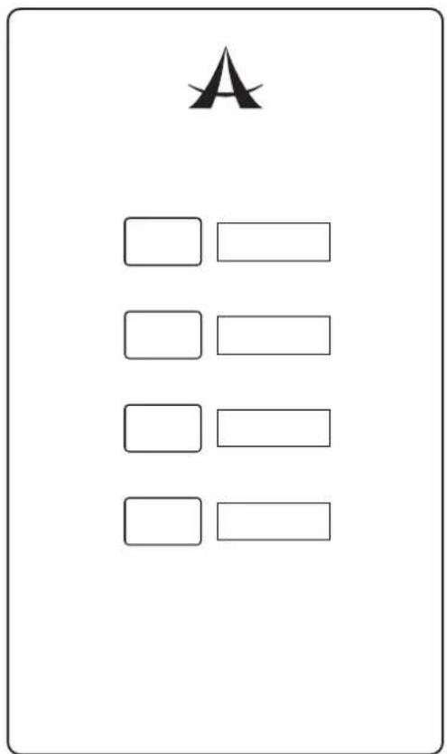
RM-4 PRESET RECALL REMOTE
With a single RM-4 you will be able to recall up to 4 independent presets.
The RM-4 can be wired to the "Preset" section on the rear of the DMP808.
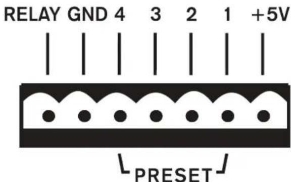
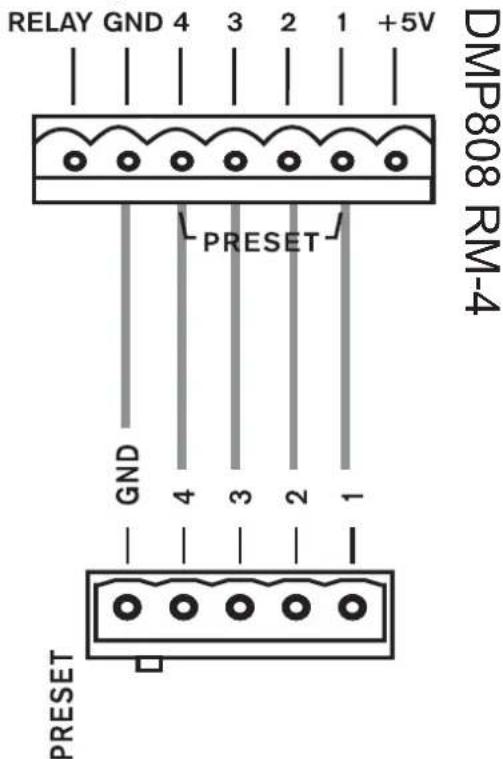
As shown, there are pins for each of the 4 preset buttons on the RM-4, as well as a grounding pin. Each of the 4 pins corresponds with a user-selected "Scene" within the control software.
Suggested wiring:
SETUP AND OPERATION
To utilize the RM-4, you simply need to assign a preset to each of the buttons. This is done within the Control Software of the DMP 808. First, enter the "Global Settings" menu and find the GPIO submenu. Here you will find the "Preset" panel (shown below). Each of the pins on the rear of the device will correspond to the Ports listed here. You can then select which "Scene" (or preset) you wish to assign to that port.

The pre-saved scenes are all listed within the Utility menu. Scenes can be saved (and recalled) in this menu. The "No" in the Preset window on the GPIO page will correspond with the 'Scene' numbers found here. The Subject in the Preset window will be updated automatically.
A single preset can be recalled at any one time. The button selected on the RM-4 will lock down, releasing any other preset button that may have previously been selected.
RM-6E PROGRAMMABLE REMOTE
With a single RM-6E you will be able to control up to 6 independent functions including gain control, channel muting and matrix mixing. Up to eight RM-6Es can be utilized at any one time.








WIRING
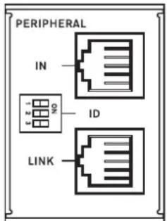
The RM-6E has an "IN" port that can be connected to the RJ-45 "Peripheral" connector on the DMP808 series of digital matrix amplifiers and processors. This is done using a typical CAT5/6 cable.
A second RM-6E can then be daisy-chained off the first by connecting the "LINK" RJ-45 connector on the first to the "IN" connector on the second. This can then be repeated for a third, a fourth, and so on. You can use a maximum of 8 RM-6E's together with your DMP808.
SETUP
The rear of the RM-6E features 3 DIP switches that can be utilized for identification of the unit. These correspond with the 8 ports available within the DMP808 software. The pin identifications and their corresponding ports are as follows:

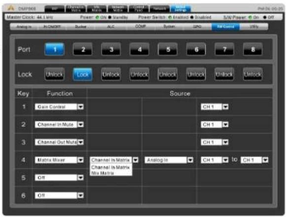
To assign a function to any of the RM-6E's buttons, you will need to enter the software of your DMP808. When in the software, navigate to the "Global Settings" tab. Within this menu there is an "RM Control" submenu that offers control of the RM-6E programmable remote controls.
The "Port" option at the top of the page will correspond with the port options found above. When the corresponding port is selected, the 6 rows in the lower-half of the page can be used to determine the operation of each individual button on the RM-6E. Available functions are: "Gain Control", "Channel In Mute", "Channel Out Mute" and "Matrix Mixer". The first three functions also have a "Source" option that simply lets you select from an available channel that you can then control. The "Matrix Mixer" function has further options, allowing you to select from the applicable matrix mix and input source.
Below the "Port" option in the control software, there is also a "Lock" option. When a port is "locked", the corresponding functions of the RM-6E assigned to this port will be deactivated and cannot be utilized using that remote unit.
OPERATION
When a function is selected, pushing the RM-6E's corresponding onboard buttons will activate said function. In the case of "Gain Control", the up/down arrow buttons are used to adjust the gain as needed. When a "Mute" function is selected, simply pushing the button will mute the selected channel/source. Finally, when the Matrix function is selected, pushing the corresponding button will route the signal selected to the mix selected. Pushing it again will un-route the signal.
With up to 8 individual RM-6E units you're able to set a maximum of 48 individual gain controls, channel mutes and/or matrix routing presets for use at any time.
SIGNAL PROCESSORS
Below you will find the onboard signal processors of the DMP808 and information on their use and respective parameter. These can be applied to any of the 8 input or 8 output channels of the DMP808.
Compressor-Limiter
Compressor Threshold: Use this control to set the threshold of the compressor function. Any signals that surpass the selected threshold will be compressed at the selected ratio.
Compressor Attack: This control adjusts the attack time of the compressor, essentially determining the time taken for the compressor to kick in after it passes the selected threshold.
Ratio: This control can be used to set the ratio for the compressor. The ratio is expressed as :
Compressor Release: The release control determines the time the DMP808 will wait before disengaging the compressor when the signal bypasses the selected threshold.
Limiter Threshold: This control determines the threshold for the limiter function. This means that no signal will surpass the selected threshold, being 'compressed' at a ratio of infinity:1.
Output Gain: This control determines the amount of gain applied to the signal after already passing through the compressor-limiter.
On & Reset Buttons: The on button is, of course, used to turn the Compressor-Limiter on and off, while the reset button will reset all values to default.
Gate
On: This button turns the gate on and off.
Reset: Push the reset button to restore all parameters back to default.
Dynamic Graph: This graph shows the currently set gate properties and how it will affect your audio.
Level Meters: These meters give the input and output level of the gate for the current channel.
Gain Reduction: The gain reduction meter will provide a real-time indication of any reduction in signal caused by the gate.
Threshold: This control will set the threshold of the gate function. Any signals that fall below the set threshold will activate the gate function.
Range: This control sets the amount of attenuation when the gate is closed.
Attack: This control adjusts the attack time of the gate. This is the time the DMP808 will wait after the signal drops below the threshold before engaging the gate.
Hold: The hold will allow you to select the length of time the gate will remain open after the signal drops below the set threshold.
Release: The release control determines how long the gate will wait before disengaging when the signal rises back above the selected threshold.
Expander
On: This button turns the expander on and off.
Reset: Push the reset button to restore all parameters back to default.
Dynamic Graph: This graph shows the currently set expander properties and how it will affect your audio.
Level Meters: These meters give the input and output level of the expander for the current channel.
Gain Reduction: The gain reduction meter will provide a real-time indication of any reduction in signal caused by the expander.
Threshold: This control will set the threshold of the expander function. Any signals that fall below the set threshold will activate the expander at the user-set ratio.
Ratio: This signal sets the ratio of the expander function. When a signal drops below the threshold, the signal will be decreased by the selected ratio.
Attack: This control adjusts the attack time of the gate. This is the time the DMP808 will wait after the signal drops below the threshold before engaging the gate.
Release: The release control determines how long the gate will wait before disengaging when the signal rises back above the selected threshold.
Delay
Adding a delay on output can be particularly helpful to help time align drivers within a single cabinet or help avoid delay in larger multi speaker setups. For example, when there are a number of drivers in a single cabinet, typically they're different distances from the front of the cabinet.
The tweeter, typically longer than the woofer, could have its driver 8 inches deeper than the woofer. The problem this creates is the sound from the woofer will be pushed out a fraction of a second before the tweeter, arriving at the wavefront at different times. Adding a 0.6 millisecond delay to the woofer can combat this, essentially making the signal wait for the tweeter to catch up.
Delay: Use this control to adjust the delay time. To the right of the control, the selected delay will be indicated in milliseconds, meters and feet.
Temperature Control: This allows you to set the current temperature for the delay circuit. This allows the DMP808 to better refine the delay's 'meter' and 'feet' results. The temperature is indicated in both degrees Celsius and degrees Fahrenheit.
On & Reset Buttons: The on button is used to turn the delay circuit on and off. The reset button resets all values to default.
Parametric Equalizers
EQ On/Off Button: This button can turn the Equalizer for the currently selected channel on and off.
Reset: Push the reset button to restore all parameters back to default.
EQ Band On/Off: Use these buttons to turn the corresponding EQ bands on and off. While not named specifically, these bands can be thought of as the low, low-mid, high-mid and high frequency bands on your average 4-band EQ.
EQ Type: For the first and fourth bands on the EQ, users can select the type of curve used for the EQ. Band 1 can be swapped between a normal EQ band (PEAK), low shelf filter (SHELF), and high pass filter (CUT). Band 4 can be selected between an EQ band (PEAK), high shelf filter (SHELF), and low pass filter (CUT). The Low/High Pass Filters will cut frequencies above and below the selected frequencies at 18 dB per octave. High and Low Shelf filters act similarly, but cut frequencies below the selected frequency by the preset level determined by the user.
EQ Parameters: The EQ offers users the ability to view or edit various parameters/properties of their EQ bands, including the Gain (dB), the frequency (Hz/kHz) and the 'Q' of the EQ band.
Meters: Both input and output meters are available for this process, essentially showing the difference in the overall signal level after equalization.
Feedback Silencer
Feedback occurs when the sound from your speakers makes its way back into the mixer through microphones. The audio look causes a high pitch squeal or screech that can easily ruin your performance. Feedback can be removed, however, by reducing or removing the problem
TROUBLESHOOTING
I don't have any output
Have you activated the output channels? Do you see a signal in the output meters? Have you correctly routed your inputs to channels, turned levels up, and unmuted mixes? Have you applied an excessive compressor-limiter to any input or output signals?
I have a signal, but it's really distorted!
Are any of the Clip LEDs lighting up for input or output mixes? Do any of the signals on your entire audio chain seem excessive? This could include input connectors, channel inputs, matrix outputs.
My devices are not communicating via Ethernet
Are the red and green LEDs on the Ethernet connectors lighting up? Are you using a decent quality Ethernet cable?
My DMP808 won't communicate with my computer
Are you using a decent quality Ethernet cable? Are your computer and DMP808 both connected to the same network? Do you have a firewall turned on?
frequencies. With a razor-thin filter, feedback can be completely removed without affecting your audio what-so-ever.
The DMP808 features a 12 filter feedback silencer. This can operate in 2 different modes: Automatic and Manual. When set to automatic, the activated filters will automatically search for and remove feedback. When set to manual, the user is able to adjust the frequency, gain and Q of the individual filters.
Parameters: When the Feedback Silencer is set to "Manual" it offers users the ability to view or edit various parameters/properties of their EQ bands, including the Gain (dB), the frequency (Hz/kHz) and the 'Q' of the 12 filters.
Threshold: Adjusting the threshold will determine the level of signal required for the automatic feedback silencer to kick in.
31-band GEQ
Graphic equalizers are fantastic in live setups where you may need to compensate for room acoustics or other factors. Include a 31-band graphic equalizer on your speaker output signals to better refine your live audio.
Frequency bands: The GEQ's frequency bands can be boost or cut by the user. Frequencies are set at fixed frequencies between 20Hz and 20kHz.
How can I use the RS-232 port?
An RS-232 connection is available on the DMP808 to allow control information to be sent to the unit without the need of Ethernet connection. Asystems has provided an implementation reference on the website.
Initializing the DMP808
The DMP808 can be initialized using the DIP switch on the rear of the device. The left-most pin will allow users to begin initializing the unit. It can be returned to the RESUME position to continue operation.
Why are the front panel VRs not working?
The rear panel has a DIP switch that controls these VRs. If set to the lower position these will be locked and you will be unable to use them.
SPECIFICATIONS
| DMP808 | |
| Input Connections | 8 x Balanced Euroblock4 x Unbalanced Stereo RCA |
| Output Connections | 8 x Balanced Euroblock |
| Control Network | Compatible with standard 10/100 MBit/s Ethernet hardware |
| Front Panel Indicators | 8 x Input/Clip, 8 x Output/Clip, 1 x Power, 1 x Network |
| Signal to Noise (20Hz-20KHz, unweighted) | >110dB |
| Frequency Response | 20Hz-20kHz, +/-1dB |
| Input Impedance | Euro: 3.52K Ω, RCA: 8.8K Ω |
| Maximum Input Level | 20dBu |
| Total Harmonic Distortion | 0.002% |
| Processor | 40-bit floating point |
| Input A/D Conversion | 24-bit |
| Output D/A Conversion | 24-bit |
| Sample Rates | 44.1 kHz, 48 kHz, Network |
| DIP Switches | Network ID, 0 - F |
| Parametric Equalizers | 4-band, adjustable Q, freq. and level |
| EQ filters | All pass, band pass, hi/lo shelf |
| Compressor | Threshold, range, attack, release |
| Ducker | Trigger, release, depth |
| Delay | Adjustable input and output delay |
| Feedback Silencer | Fixed/Dynamic |
| Auto-mixing | NOM attenuation max. |
| Phantom Power | +48V DC |
| Crossover | Butterworth |
| Power & Physical | |
| Power Supply | 120VAC/240VAC switching power supply, 15A Edison cable |
| External Power | 2-pin euroblock, +24V DC |
| Dimensions | 44 x 484 x 295 mm (1.7" x 19" x 11.6") |
| Weight | 4.2 kg (9.3 lbs) |
PARAMETERS
| Function Parameter Range | ||
| Compressor / Limiter | Compressor Threshold -50 dB to 0 dB | |
| Ratio 1:1 to 20:1 | ||
| Limiter Threshold -50 dB to 0 dB | ||
| Output Gain 0 dB to 18 dB | ||
| Attack / Release 1 ms to 8 seconds | ||
| Gate | Threshold -50 dB to 0 dB | |
| Range -90 dB to 0 dB | ||
| Attack / Hold / Release 1 ms to 8 seconds | ||
| Expander | Threshold -50 dB to 0 dB | |
| Ratio 1:1 to 20:1 | ||
| Attack / Release 1 ms to 8 seconds | ||
| Delay | Delay Time (mS) 0.0 to 680.0 ms | |
| Delay Time (meters) 0.0 to 245.5 | ||
| Delay Time (feet) 0.0 to 805.4 | ||
| Temperature (C) 0° to 50° | ||
| Temperature (F) 32° to 122° | ||
| 4-band Equalizer | Type | BPF, Notch, Peak, HPF, LPF, High Shelf, Low Shelf |
| Gain | -18 dB to +18 dB | |
| Frequency | 20 Hz to 20 kHz | |
| Q | 0.1 to 10 | |
| 31-band Graphic EQ | Frequencies | 20 Hz to 20 kHz |
| Range | -12dB to +12dB | |
| Q | 1.6 to 10 | |
| Filters | Type | HPF (6 dB, 12 dB, 18dB, 24dB), LPF (6 dB, 12 dB, 18dB, 24dB), High Shelf, Low Shelf, Peak, APF, BPF, Notch |
| Gain | -18 dB to +18 dB | |
| Frequency | 20 Hz to 20 kHz | |
| Q | 0.1 to 10 | |
| Feedback Silencer | Threshold -50 dB to 0 dB | |
| Release Time | 10 sec/dB to 300 sec/dB | |
| Gain | -20 dB to 0 dB | |
| Frequency | 20 Hz to 20 kHz | |
| Q | 4.5 to 10 | |
| Automatic Level Control | In Target 0 dB to -50 dB | |
| Below Target -30 dB to 0 dB | ||
| Ratio | 1:5~20:1 | |
| Increase Gain | 40ms/dB to 1000ms/dB | |
| Decrease Gain | 1000ms/dB to 40ms/dB | |
| Hold Time | 0s to 10s | |
| Ducker | Source | Analog 1 to 8, EX 9 to 12, Network 1 to 8 |
| Threshold -50 dB to 0 dB | ||
| Depth | -80 dB to 0 dB | |
| Attack / Release | 0.2s to 20s | |
| Signal Generator | Sine Wave Frequencies | 20Hz to 20KHz |
| Sweep Wave Start/End Frequencies | 20Hz / 20KHz | |
| Sweep Wave Hold Time | 50ms to 2000ms | |
| Signal Level Range -60dB to -10dB |
CONTENIDO
IMPORTANT SAFETY INSTRUCTIONS
- Read these instructions – All the safety and operating instructions should be read before this product is operated.
- Keep these instructions – The safety and operating instructions should be retained for future reference.
- Heed all warnings – All warnings on the appliance and in the operating instructions should be adhered to.
- Follow all instructions – All operating and use instructions should be followed.
- Do not use this apparatus near water – The appliance should not be used near water or moisture – for example, in a wet basement or near a swimming pool, and the like.
- Clean only with dry cloth.
- Do not block any ventilation openings. Install in accordance with the manufacture's instructions.
- Do not install near any heat sources such as radiators, heat registers, stoves, or other apparatus (including amplifiers) that produce heat.
- Do not defeat the safety purpose of the polarized or grounding plug. A polarized plug has two blades with one wider than the other. A grounding plug has two blades and a third grounding prong. The wide blade or the third prong is provided for your safety. If the provided plug does not fit into your outlet, consult an electrician for replacement of the obsolete outlet.
- Protect the power cord from being walked on or pinched particularly at the plugs, convenience receptacles, and at the point where they exit from the apparatus.
- Only use attachments/accessories specified by the manufacturer.
- Use only with the cart, stand, tripod, bracket, or table specified by the manufacturer, or sold with the apparatus. When a cart or rack is used, use caution when moving the cart/apparatus combination to avoid injury from tip-over.
- Unplug the apparatus during lightning storms or when unused for long periods of time.
- Refer all servicing to qualified personnel. Servicing is required when the apparatus has been damaged in any way, such as power supply cord or plug is damaged, liquid has been spilled or objects have fallen into the apparatus has been exposed to rain or moisture, does not operate normally, or has been dropped.
-
CAUTION: These servicing instructions are for use by qualified service personnel only. To reduce the risk of electric shock, do not perform any servicing other than that contained in the operating instructions unless you are qualified to do so.
-
Do not install this equipment in a confined or building-in space such as a book case or similar unit, and remain a well ventilation conditions at open site. The ventilation should not be impeded by covering the ventilation openings with items such as newspaper, table-cloths, curtains, etc.
- WARNING: The mains plug/appliance coupler is used as disconnect device, the disconnect device shall remain readily operable.
- This apparatus is for professional use only.

CAUTION: TO REDUCE THE RISK OF ELECTRIC SHOCK, DO NOT REMOVE COVER (BACK). NO USER-SERVICEABLE PARTS INSIDE. REFER SERVICING TO QUALIFIED PERSONNEL.
-
WARNING: To reduce the risk of fire or electric shock, do not expose this apparatus to rain or moisture. The apparatus shall not be exposed to dripping or splashing and that objects filled with liquids, such as vases, shall not be placed on apparatus.
-
This lightning flash with arrowhead symbol within an equilateral triangle is intended to alert the user to the presence of non-insulated "dangerous voltage" within the product's enclosure that may be of sufficient magnitude to constitute a risk of electric shock.
Warning: To reduce the risk of electric shock, do not remove cover (or back) as there are no user-serviceable parts inside. Refer servicing to qualified personnel.

- Protective earthing terminals. The apparatus should be connected to a mains socket outlet with a protective earthing connection.

INTRODUCCIÓN
![graph TD A["Internet Port"] --> B["USB Cable"] B --> C["Laptop"] C --> D["USB Cable"] D --> E["USB Cable"] E --> F["USB Cable"] F --> G["USB Cable"] G --> H["USB Cable"] H --> I["USB Cable"] I --> J["USB Cable"] J --> K["USB Cable"] K --> L["USB Cable"] L --> M["USB Cable"] M --> N["USB Cable"] N --…](/content/2026/05/1083949/images/8848113cb26791930029b50e3391b7689f8903967024480481a4ecb22a454b76.jpg)
- On login page, enter the following information.
Security
ALC - Auto Level Control
Utility/Utilidades
SYSTEMS
www.asystems-sys.com


- IMPORTANT SAFETY INSTRUCTIONS
- INTRODUCTION
- FEATURES
- GETTING STARTED
- GLOSSARY
- CONTROLS & SETTINGS
- FRONT PANEL
- MOUNTING HOLES
- POWER SWITCH
- POWER LED
- DISABLE LED
- OUTPUT LEDS
- SIGNAL/CLIP LED
- GAIN CONTROLS
- REAR PANEL
- ETHERNET CONNECTION
- PERIPHERAL ETHERNET CONNECTION
- EUROBLOCK LINE INPUTS
- EUROBLOCK LINE OUTPUTS
- RCA INPUTS
- UNIT ID CONTROLS & DIP SWITCH
- 24VDC INPUT
- GPIO IN
- GPIO OUT
- DIGITAL I/O EXPANSION SLOT
- AC POWER CONNECTOR
- DMP808 DIP SWITCH SETTINGS
- DANTE CONNECTIVITY [DMP808D ONLY]
- GENERAL SETTINGS
- RESTORE FACTORY SETTINGS
- ACTIVATING VR CONTROLS
- FIRMWARE UPDATE
- HOW TO SET THE SYSTEM IP ADDRESS
- DMP808 CONTROL SOFTWARE
- CONNECTION
- DSP
- CHANNEL IN MATRIX
- MIX MATRIX
- SIGNAL GENERATOR
- NETWORK MATRIX
- CONTROL PANEL
- NETWORK
- SET VIA SYSTEM HARDWARE
- SET VIA SOFTWARE
- SECURITY
- GLOBAL SETTINGS
- ANALOG IN
- GLOBAL IN ON/OFF
- DUCKER
- ALC – AUTO LEVEL CONTROL
- COMPRESSOR/LIMITER
- SYSTEM
- RELAY I/O (GPIO)
- RM CONTROL
- UTILITY
- RM-4 PRESET RECALL REMOTE
- SETUP AND OPERATION
- RM-6E PROGRAMMABLE REMOTE
- WIRING
- SETUP
- OPERATION
- SIGNAL PROCESSORS
- COMPRESSOR-LIMITER
- GATE
- EXPANDER
- DELAY
- PARAMETRIC EQUALIZERS
- FEEDBACK SILENCER
- TROUBLESHOOTING
- I DON'T HAVE ANY OUTPUT
- I HAVE A SIGNAL, BUT IT'S REALLY DISTORTED
- MY DEVICES ARE NOT COMMUNICATING VIA ETHERNET
- MY DMP808 WON'T COMMUNICATE WITH MY COMPUTER
- 31-BAND GEQ
- HOW CAN I USE THE RS-232 PORT
- INITIALIZING THE DMP808
- WHY ARE THE FRONT PANEL VRS NOT WORKING
- CONTENIDO
- INTRODUCCIÓN
- ALC - AUTO LEVEL CONTROL
- UTILITY/UTILIDADES
Brand : PHONIC
Model : DMP808D
Category : Audio Mixer