
WV100 - Hand blender Bogen - Free user manual and instructions
Find the device manual for free WV100 Bogen in PDF.


| Product Type | Hand Blender |
| Brand | Bogen |
| Model | WV100 |
| Dimensions (L x W x H) | Approx. 40 cm x 7 cm x 7 cm (blending shaft length 20 cm) |
| Weight | Approx. 0.8 kg |
| Power Consumption | 300 W |
| Voltage / Frequency | 220-240 V / 50-60 Hz |
| Power Cord Length | 1.5 m |
| Speed Settings | 2 speeds + turbo boost |
| Blending Shaft Material | Stainless steel |
| Motor Housing Material | Plastic with soft-grip handle |
| Ergonomic Grip | Yes, non-slip handle |
| Ice Crushing Capability | Yes |
| Safety Features | Overheat protection, automatic shut-off, safety switch |
| Cleaning | Detachable shaft, dishwasher safe; motor unit wipe clean only |
| Included Accessories | Stainless steel blending shaft, user manual, warranty card |
| Warranty | 1 year |
| Spare Parts Availability | Replacement shafts and whisks available from Bogen |
| Noise Level | Approx. 80 dB (A) |
| Certifications | CE, RoHS |
Frequently Asked Questions - WV100 Bogen
User questions about WV100 Bogen
0 question about this device. Answer the ones you know or ask your own.
Ask a new question about this device
Download the instructions for your Hand blender in PDF format for free! Find your manual WV100 - Bogen and take your electronic device back in hand. On this page are published all the documents necessary for the use of your device. WV100 by Bogen.
USER MANUAL WV100 Bogen
Wall-Mount Power Vector Amplifiers WV100, WV150, & WV250 Models
Installation and Use Manual
© 2002 Bogen Communications, Inc.
All rights reserved.
Specifications subject to change without notice.
54-2086-01E 1204
Notice
Every effort was made to ensure that the information in this guide was complete and accurate at the time of printing. However, information is subject to change.
Important Safety Information
WARNING: To Reduce The Risk of Fire Or Electric Shock, Do Not Expose This Apparatus To Rain Or Moisture.
Always follow these basic safety precautions when installing and using the unit:
- Read these instructions.
- Keep these instructions.
- Heed all warnings.
- Follow all instructions.
- Do not use this apparatus near water.
- Clean only with dry cloth.
- DO NOT block any ventilation openings. Install in accordance with the manufacturer's instructions.
- Do not install near any heat sources such as radiators, heat registers, stoves, or other apparatus (including amplifiers) that produce heat.
- Do not defeat the safety purpose of the polarized or grounding-type plug. A polarized plug has two blades with one wider than the other. A grounding-type plug has two blades and a third grounding prong. The wide blade, or the third prong, are provided for your safety. If the provided plug does not fit into your outlet, consult an electrician for replacement of the obsolete outlet.
- Protect the power cord from being walked on or pinched, particularly at plugs, convenience receptacles, and the point where they exit from the apparatus.
- Only use attachments/accessories specified by the manufacturer.
- Unplug this apparatus during lightning storms or when unused for long periods of time.
- Refer all servicing to qualified service personnel. Servicing is required when the apparatus has been damaged in any way, such as power supply cord or plug is damaged, liquid has been spilled or objects have fallen into the apparatus, the apparatus has been exposed to rain or moisture, does not operate normally, or has been dropped.
IMPORTANT
CAUTION
RISK OF ELECTRIC SHOCK DO NOT OPEN
CAUTION: TO PREVENT THE RISK OF ELECTRIC SHOCK, DO NOT REMOVE COVER (OR BACK). NO USER-SERVICEABLE PARTS INSIDE. REFER SERVICING TO QUALIFIED PERSONNEL.

The lightning flash with arrowhead symbol, within an equilateral triangle, is intended to alert the user to the presence of uninsulated “dangerous voltage” within the product’s enclosure that may be of sufficient magnitude to constitute a risk of electric shock to persons.

The exclamation point within an equilateral triangle is intended to alert the user to the presence of important operating and maintenance (servicing) instructions in the literature accompanying the appliance.
Contents
Page
PANEL DESCRIPTIONS....2-3
Wall-Mount Power Vector Front Panel 2
Wall-Mount Power Vector Module Bay (Rear) 3
Wall-Mount Power Vector Connector Board (Rear)....3
INSTALLATION ....4
Package Contents 4
Mounting....4
Front Panel Input Connector....4
MODULES ....5
Module Installation 5
Output Modules 5
Functionality 5
Input Modules 5
Functionality 5
Priorities ....5
CONNECTIONS 6-8
Speakers 6
Transformer-Coupled Speaker Connections 6
4-Ohm Low-Impedance Speaker Connections....6
COM and GND Terminals 7
Remote Volume Control....7
Mute Control....7
Bridging Mix Bus 7
System Expansion of Power Vector Amplifiers 8
OPERATION 9-10
Front Panel Controls & Indicators 9
Input Volume Controls 9
Signal / Clip Indicator 9
Bass and Treble Controls....9
Master Volume Control 9
Average / Peak Switch & LED Output Meter 9
Power Switch / Power Indicator 9
Output Limiter....10
Rear Panel Controls 10
Trans Output / Direct Out Selector Switch 10
Other Controls 10
Tone Control Bypass Switch....10
Low-Cut Switch 10
BLOCK DIAGRAM ....11
SPECIFICATIONS 12
TROUBLESHOOTING 13
LIMITED WARRANTY......Back Cover
ACCESSORIES/COMPONENTS ....Back Cover
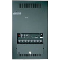
Wall-Mount Power Vector Front Panel
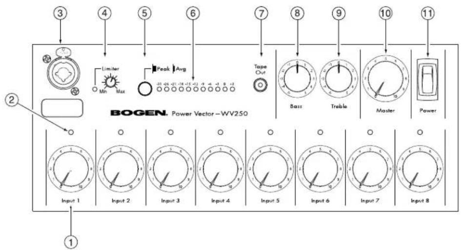
1. Input Volume Control
Each of the 8 module bays are controlled by an independent volume control.
2. Signal / Clip Indicator
A single two-color LED located above each channel's volume control indicates the audio activity of that channel's input. Green indicates signal active at the input; red indicates clipping of the input signal.
3. Panel Input Connector
A combination XLR female and 1/4" stereo phone jack connector provides a panel-mounted input. Parts included, but comes uninstalled.
4. Output Limiter Control with Indicator
Control determines maximum amp output level before limiting takes place. Indicator illuminates when limiting takes place.
5. Average / Peak Switch
This switch determines whether the LED Output Meter registers the average or peak level of the amplifier's output.
6. LED Output Level Meter
An 11-segment LED output level meter monitors the output level of the power amplifier.
7. Tape Out
RCA unbalanced signal level output post bass, treble, and master controls.
8. Bass Control
Controls the amount of cut or boost of bass frequencies below 100 Hz.
9. Treble Control
Controls the amount of cut or boost of treble frequencies above 10 kHz.
10. Master Volume Control
Controls overall level of mixed input signals.
11. Power Switch
Controls AC power to the amplifier. Illuminates when ON.
Wall-Mount Power Vector Module Bay (Rear)

1. Module Bays
The amplifier has eight module bays, all of which can accommodate input modules, with two bays (bays 7 and 8) that can accommodate either input or output modules.
2. Lo-Cut Switch
Slide switch (located in module bay 6) allows roll off of frequencies below 125 Hz.
3. Tone Control Bypass Switch
Slide switch (located in module bay 6) allows the effects of the Bass and Treble controls to be bypassed.
Wall-Mount Power Vector Connector Board (Rear)

1. Trans Output / Direct Out Selector
Allows selection of either "TRANS" for transformer-coupled outputs (70V, 25V, and 8-ohm), or "DIR" for direct low-impedance (4-ohm minimum) output.
2. Speaker Output Barrier Strip
A terminal barrier strip, with clamping washers, provides connections for speaker loads.
3. Mute Control Terminals
Provides access to mute buses for external control and system expansion.
4. Bridging Mix Bus
An RCA connector that allows the bridging of Power Vectors together for system expansion.
5. Remote Volume Control Terminals
Provides for connection of an RVCP remote volume control panel to control the amplifier's motorized Master Volume Control.
Package Contents
- Amplifier • 2 Cables
- Instruction Manual • Combined XLR receptacle and phone jack
• 2 Screws (M 3 x 8) • 6 Screws (M 4 x 8)
Mounting
A surface-mount (model BBS) or flush-mount (model BBF shown below) back box as well as a WMAD door is required for installation. Refer to the instructions provided with these items for proper installation. (See Components on Back Cover.)

WARNING:
To prevent injury, this apparatus must be securely attached to the wall in accordance with the installation instructions.
Front Panel Input Connector
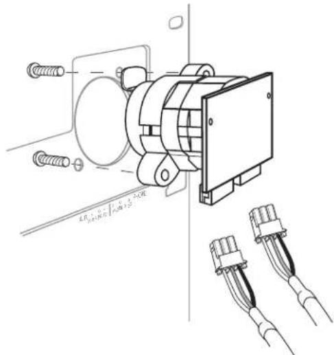
If desired, a front panel mounted combination female XLR and 1/4" stereo phone jack can be installed. A white screened area is provided on the front of the amplifier, below the connector, to identify the connector's purpose and associated input number. Remove the filler cap in the upper left-hand corner of the front panel and install the combination jack as shown in the figures below. Either or both of the connector styles on the jack can be wired to any user-supplied module with included cables. The labeling below the two cable connectors on the PCB identifies corresponding connectors on the combo jack.


Connection Identifiers
Module Installation
Eight module bays are available to accept Bogen's new advanced plug-in input modules. Module bays 7 & 8 can also accommodate Bogen's new advanced plug-in output modules, thereby allowing users to customize the amplifier to suit the needs of the installation.
(Note: The bays will not accept Bogen's older style D-Series plug-in modules.)
Before installing a module, read the instructions included with the module and make the desired jumper setting changes.
The modules are installed by simply sliding them along the card guides inside the module bays until the faceplate firmly sits against the chassis, then use the two screws supplied with the module to secure it to the chassis.
- CAUTION - DO NOT FORCE MODULES
- Modules should slide in easily.
- Output modules can only be installed in bays 7 & 8. (Output modules will not fit in bays 1-6.)
- Output modules have 8 contacts on each side of the connector.
- Input modules have 6 contacts on each side of the connector.
- Older style Bogen (D-Series) input modules (4-1/2" in length) are not usable in any Power Vector amp.
Output Modules
Functionality
The Wall-Mount Power Vector series of amplifiers accepts Bogen plug-in output modules, which offer a cost effective and convenient way to add specific signal processing capability into a system. When an output module is installed, the mix bus signal is automatically rerouted through the output module, whose capabilities further process the signal before it enters the power amplifier section.
Up to 2 output modules can be installed in a Power Vector amplifier using module bays 7 & 8 (or these bays can accept input modules). When two output modules are installed, their signal processing effects are cascaded. The mix bus signal will first pass through the output module in module bay 7 and then through the output module in bay 8. In some instances, the order in which the signal processing is applied is important and can be achieved by the module installation order.
Output modules automatically insert themselves into the signal path between the mix bus and power amp stage, so no further connections are required beyond simply inserting the modules. Most Bogen output modules include an unbalanced, Hi-Z input. This input feeds directly to the amplifier's mix bus through the front level control for the particular module bay and is not processed by the output module directly. The input is included so that the additional input function of the module bay is not forfeited when an output module is installed.
Input Modules
Functionality
The Wall-Mount Power Vector series of amplifiers accepts Bogen's new advanced plug-in input modules, which provide a wide range of input types allowing the amplifier inputs to be custom configured in both type and number for a particular application. Input modules can be installed in any of the 8 module bays and do not have to be installed in any particular bay order. The front panel volume control for that number bay will control the mix level of that input module. In addition to a host of module specific features, each input module has a priority jumper section for creating a priority hierarchy between different inputs installed in the amplifier.
Priorities
The Wall-Mount Power Vector series of amplifiers allows inputs to be prioritized at four different levels. The Bogen input modules contain circuitry that can cause their outputs to be muted in response to higher priority control signals from other input modules. Each input module also contains circuitry that sends a mute control signal out to other modules when it becomes active (all input modules become “active” when they receive an audio input). Active modules may be prevented from sending their audio onto the mix bus by a higher priority module that is also active.
Input priorities are set through a simple jumper field on the module. It is also possible not to assign a priority level to an input module. By doing so, that module will never be muted by another input module in the amplifier. The unassigned inputs will, however, be muted by the amplifier's Master Mute input.
Speakers
Transformer-Coupled Speaker Connections
Transformer-coupled, constant voltage speaker loads are connected to their respective load type (i.e., 70V speakers to the 70V terminal, 25V speaker systems to the 25V terminals) and the COM terminal. Make sure the selector switch is in the TRANS position. A separate 8-ohm terminal is provided to drive 8-ohm (low-impedance) speakers through an output transformer tap.
The speaker terminals can accept up to a #10 spade lug and have integral clamping plates that make wiring easier.
4-Ohm Low-Impedance Speaker Connections
A low-impedance (4Ω) speaker load can be driven directly (without transformer coupling) by connecting the load to the 4Ω terminal and the GND terminal. Make sure the selector switch is in the DIR position.
Bypassing the output transformer and driving the speaker load directly provides the advantage of better bass response. To maximize the power delivered to the speakers, their combined load impedance should be 4 ohms. Connecting higher load impedances is electrically acceptable, but the mismatch in load impedance will cause the speaker load to only receive a portion of the power that the amplifier is capable of delivering. It is not acceptable to connect low-impedance speakers to the 70V and 25V outputs.

Typical connections to a 70V transformer-coupled speaker

Typical connections to a low-impedance (non-transformer-coupled) speaker load
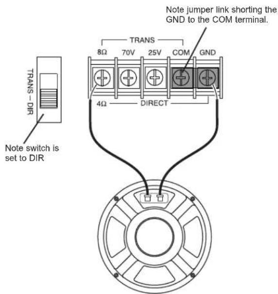
COM and GND Terminals
A shorting jumper typically connects the COM and GND terminals of the amplifier together. The COM terminal is a common lead from the output transformer. For the transformer-coupled speaker output to work, one of the speaker load leads must be connected to this terminal. The GND terminal is a connection to the system's electrical ground and used when driving loads in the Direct Out mode.
Connecting the GND to the COM terminal when using the transformer-coupled outputs references the transformer output to ground. Disconnecting the GND terminal from COM allows the transformer output to float electrically. This is sometimes useful under certain conditions where a ground connection is undesirable. It is generally a good idea, however, to short the GND to the COM terminal regardless of output type (Trans or Direct).
Remote Volume Control
These terminals are provided for remote control of the Master Volume control. This control is motorized, allowing full control over the setting of the master volume. The Bogen Remote Volume Control Panel (model RVCP) provides a simple and elegant means of remote control. Shorting the UP terminal with the C terminal will rotate the Master Volume control in a clockwise direction, increasing the volume level. Shorting the DN terminal to the C terminal will cause the Master Volume control to rotate in a counterclockwise direction and decrease the level of the Master Volume control. The impedance of the shorting connections must be less than 100 ohms in order to operate the control.
Mute Control
Each priority bus (High, Medium, and Low) can be externally activated. This allows priority buses of two or more Wall-Mount Power Vector units to be linked together for system expansion purposes. A particular mute priority can be externally forced by shorting that priority's bus terminal to the C terminal of the Mute Control (the C terminal is the system ground). Forcing the H priority bus this way will mute all modules except for modules set for priority level 1 (highest priority). Forcing the M priority bus will mute modules set for priority levels 3 or 4, but not levels 1 or 2, and forcing the L priority bus will only mute modules set at priority level 4. See System Expansion of Power Vector Amplifiers section and illustration on page 8.
Bridging Mix Bus
This connector makes the Wall-Mount Power Vector's mix bus available externally and allows the connecting of Power Vector units for system expansion and simple room combining.
This function is bi-directional. Any signal received will be amplified and any signal sent can be used by another Power Vector amp. The signal levels at the bridging jack will drop by one-half with two Power Vectors tied together and by two-thirds with three units tied together. Because of the attenuation of the bridging signal, due to the signal loading of other Power Vectors, it is not recommended that more than three units be connected together. See Mute Control section and the illustration on the next page for additional information.


MIX BUS IN/OUT

System Expansion of Power Vector Amplifiers
Using the bridging RCA connector, it is possible to connect two or more Power Vector amplifiers. It is not recommended that more than three amplifiers be bridged together due to bridging loss. When connecting mute control functions, make certain that the wiring is consistent (H to H, M to M, and so forth). See illustration below.

Front Panel Controls & Indicators
Input Volume Controls
Each input module may be individually controlled by its corresponding volume control knob.
Signal / Clip Indicator
A single LED located above each channel's volume control indicates the audio activity of that channel's input. Green indicates signal is being applied to the mix bus. Red indicates that the input signal coming from the input module into the amp is clipping and distorted. This is caused by either an input signal that is too high or an input module volume control (gain) that is set too high.
Bass and Treble Controls
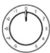
The treble control has a cut/boost range of +/- 10 dB at frequencies above 10 kHz and provides a roll off after 20 kHz to reduce gain above the audio range.
The bass control has a cut/boost range of +/- 10 dB at frequencies below 100 Hz. When driving speakers using the direct-coupled output terminals, the bass filter's response is constant to 20 Hz. When driving speakers using the transformer-coupled output terminals, the amplifier automatically changes the bass filter's response to a bandpass shape to reduce the level of bass frequencies below 40 Hz. This filter shape helps to avoid overdriving the speaker's coupling transformer with low frequency signals that may cause noticeable distortion due to magnetic saturation of the transformer's core.
Master Volume Control
The overall volume level of the amplifier is set by a Master Volume control. The Master Volume control is motorized and can be controlled by manually adjusting the knob or by a remotely-mounted control station. Connections and requirements for the remote control station (optional accessory) are described in the Connections section, under Remote Volume Control.
Average / Peak Switch & LED Output Meter
The LED Output Meter is an 11-segment meter that registers either the average or the peak level of the amplifier's output signal. A red indicator is provided at the +3 dB level to indicate amplifier clipping. Amber indicators at the 0 dB and -3 dB levels indicate high amplifier output levels. The remaining 8 indicators (green) provide an indication of the output signal's dynamics. The meter can be set to read either the average output signal level or the peak output signal levels by using the Average / Peak Switch to the left of the meter. In is average; out is peak.
Power Switch / Power Indicator
The AC power to the amplifier is controlled by the Power rocker switch, which illuminates when power is applied.


Bass
Treble

Master


Power
Output Limiter
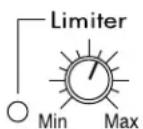
The Output Limiter control sets the threshold at which the unit hard limits the output signal. Once the Limiter's threshold is exceeded, the output signal is prevented from increasing any further. With the control set to the Min position (fully counterclockwise), the Limiter will provide almost no limiting and is essentially turned off. It will only engage when very large output levels are produced. As the control is turned clockwise, more limiter function will be allowed and the output level necessary to engage the Limiter decreases.
Typically, the Limiter is set to prevent clipping caused by overdriving the amplifier beyond its maximum output level. This setting is established by using both the Output Level Meter and the Limiter LED.
First, adjust the amplifier's output level until the Output Level Meter registers in the amber region. Then, adjust the Output Limiter control until the Limiter LED illuminates intermittently. The LED associated with the Limiter illuminates when the Limiter is engaged. If the output level of the amplifier exceeds this point, then the Limiter will engage, thereby keeping the Output Level Meter in the amber region. The Limiter can also be set to restrict the amplifier's output level to a desired level below the amplifier's maximum level to provide a means of limiting the system's volume level. In this case, the amplifier is driven to the desired output level and then the Limiter control is adjusted so that it begins to engage. In general, input and master controls should be set so that the Limiter engages as little as possible.
Rear Panel Controls
Trans Output / Direct Out Selector Switch
A large slide switch next to the amplifier's output barrier strip determines transformer-coupled or direct output operation. The setting of this switch controls which amplifier output terminals are active and what type of filter shape will be used for the bass control. See the Connections section for more information about the load selector switch.

Other Controls (Located In Module Bay 6)
Tone Control Bypass Switch
A slide switch that can bypass the effects of the Bass and Treble controls is located on the back plane of module bay 6. It is sometimes desirable to bypass the tone controls when other forms of system equalization are used. A screwdriver can be used to set the switch. The switch must be set before a module is installed in this bay.
Lo-Cut Switch
The Power Vector Amplifier provides a lo-cut filter that rolls off frequencies below 125 Hz. The slide switch for this function is located on the back plane of module bay 6. A screwdriver can be used to set the switch. The switch must be set before a module is installed in this bay.


flowchart
graph TD
    subgraph INPUT Modules
        A["Signal/Clip Indicator"] --> B["MODULE 1"]
        C["Signal/Clip Indicator"] --> D["MODULE 2"]
        E["Signal/Clip Indicator"] --> F["MODULE 3"]
        G["Signal/Clip Indicator"] --> H["MODULE 4"]
        I["Signal/Clip Indicator"] --> J["MODULE 5"]
        K["Signal/Clip Indicator"] --> L["MODULE 6"]
        M["Output Module 7 (Input or Output)"]
    end

    subgraph OUTPUT Modules
        N["Signal Processing Circuit"] --> O["OUT"]
        P["Unbalanced Hi-Impedance Aux Input"] --> Q["Inverter"]
        R["Output Module 8 (Input or Output)"]
        S["Large Card Edge Connector"] --> T["+V"]
        U["Large Card Edge Connector"] --> V["+V"]
    end

    subgraph OUTPUT Modules
        W["Power Amplifier Stage"] --> X["TAPE OUT"]
        Y["Transformer"] --> Z["Buffer Amp"]
        AA["Limiter"] --> AB["Laser"]
        AC["LED Level Meter"] --> AD["Avg./ Peak"]
        AE["TRANS OUT / DIRECT OUT SELECTOR SWITCH"] --> AF["4"]
        AG["4 OHm"] --> AH["TRANS OUT"]
        AI["25V"] --> AJ["4 ohm"]
        AK["70V"] --> AL["70V"]
        AM["COM"] --> AN["COM"]
        AO["GND"] --> AP["GND"]
    end

    subgraph OUTPUT Modules
        AQ["Signal/Clip Indicator"] --> AR["MODULE 1-6"]
        AS["Signal/Clip Indicator"] --> AT["MODULE 1-6"]
        AU["Signal/Clip Indicator"] --> AV["MODULE 1-6"]
        AW["Signal/Clip Indicator"] --> AX["MODULE 1-6"]
        AY["Signal/Clip Indicator"] --> AZ["MODULE 1-6"]
        BA["Signal/Clip Indicator"] --> BB["MODULE 1-6"]
        BC["Signal/Clip Indicator"] --> BD["MODULE 1-6"]
        BE["Signal/Clip Indicator"] --> BF["MODULE 1-6"]
        BG["Signal/Clip Indicator"] --> BH["MODULE 1-6"]
    end

    subgraph OUTPUT Modules
        BI["Signal/Clip Indicator"] --> BJ["MODULE 2-6"]
        BK["Signal/Clip Indicator"] --> BL["MODULE 2-6"]
        BM["Signal/Clip Indicator"] --> BN["MODULE 2-6"]
        BO["Signal/Clip Indicator"] --> BP["MODULE 2-6"]
        BQ["Signal/Clip Indicator"] --> BR["MODULE 2-6"]
        BS["Signal/Clip Indicator"] --> BT["MODULE 2-6"]
        BU["Bras/Treble"] --> BV["Bridging"]
    end

    subgraph OUTPUT Modules
        BW["Bras/Treble"] --> BX["Bridging"]
    end

    subgraph OUTPUT Modules
        BY["Bras/Treble"] --> BZ["Bridging"]
    end

    subgraph OUTPUT Modules
        CA["Bras/Treble"] --> CB["Bridging"]
    end

    subgraph OUTPUT Modules
        CC["Bras/Treble"] --> DD["Bridging"]
    end

    subgraph OUTPUT Modules
        DE["Bras/Treble"] --> DF["Bridging"]
    end

    subgraph OUTPUT Modules
        DG["Bras/Treble"] --> DF
    end

    subgraph OUTPUT Modules
        DH["Bras/Treble"] --> DF
    end

    subgraph OUTPUT Modules
        DI["Bras/Treble"] --> DF
    end

    subgraph OUTPUT Modules
        DJ["Bras/Treble"] --> DF
    end

    subgraph OUTPUT Modules
        DK["Bras/Treble"] --> DF
    end

    subgraph OUTPUT Modules
        DL["Bras/Treble"] --> DF
    end

    subgraph OUTPUT Modules
        DS["Bras/Treble"] --> DF
    end

    subgraph OUTPUT Modules
        DT["Bras/Treble"] --> DF
    end

    subgraph OUTPUT Modules
        DU["Bras/Treble"] --> DF
    end

    subgraph OUTPUT Modules
        DV["Bras/Treble"] --> DF
    end

    subgraph OUTPUT Modules
        DW["Bras/Treble"] --> DF
    end

    subgraph OUTPUT Modules
        DX["Bras/Treble"] --> DF
    end

    subgraph OUTPUT Modules
        DXB["Bras/Treble"] --> DF
    end

    subgraph OUTPUT Modules
        DXC["Bras/Treble"] --> DF
    end

    subgraph OUTPUT Modules
        DXD["Bras/Treble"] --> DF
    end

    subgraph OUTPUT Modules
        DXE["Bras/Treble"] --> DF
    end

    subgraph OUTPUT Modules
        DXF["Bras/Treble"] --> DF
    end

    subgraph OUTPUT Modules
        DXG["Bras/Treble"] --> DF
    end

    subgraph OUTPUT Modules
        DXH["Bras/Treble"] --> DF
    end

    subgraph OUTPUT Modules
        DXI["Bras/Treble"] --> DF
    end

    subgraph OUTPUT Modules
        DXJ["Bras/Treble"] --> DF
    end

    subgraph OUTPUT Modules
        DXK["Bras/Treble"] --> DF
    end

    subgraph OUTPUT Modules
        DXL["Bras/Treble"] --> DF
    end

    subgraph OUTPUT Modules
        DXM["Bras/Treble"] --> DF
    end

    subgraph OUTPUT Modules
        DXN["Bras/Treble"] --> DF
    end

    subgraph OUTPUT Modules
        DXO["Bras/Treble"] --> DF
    end

    subgraph OUTPUT Modules
        DXP["Bras/Treble"] --> DF
    end

    subgraph OUTPUT Modules
        DXQ["Bras/Treble"] --> DF
    end

    subgraph OUTPUT Modules
        DXR["Bras/Treble"] --> DF
    end

    subgraph OUTPUT Modules
        DXS["Bras/Treble"] --> DF
    end

    subgraph OUTPUT Modules
        DXT["Bras/Treble"] --> DF
    end

    subgraph OUTPUT Modules
        DXU["Bras/Treble"] --> DF
    end

    subgraph OUTPUT Modules
        DXV["Bras/Treble"] --> DF
    end

    subgraph OUTPUT Modules
        DXW["Bras/Treble"] --> DF
    end

    subgraph OUTPUT Modules
        DXX["Bras/Treble"] --> DF
    end

    subgraph OUTPUT Modules
        DXY["Bras/Treble"] --> DF
    end

    subgraph OUTPUT Modules
        DXZ["Bras/Treble"] --> DF
    end

    subgraph OUTPUT Modules
        DXYB["Bras/Treble"] --> DF
    end

    subgraph OUTPUT Modules
        DXZC["Bras/Treble"] --> DF
    end

    subgraph OUTPUT Modules
        DXZD["Bras/Treble"] --> DF
    end

    subgraph OUTPUT Modules
        DXZE["Bras/Treble"] --> DF
    end

    subgraph OUTPUT Modules
        DXZF["Bras/Treble"] --> DF
    end

    subgraph OUTPUT Modules
        DXZG["Bras/Treble"] --> DF
    end

    subgraph OUTPUT Modules
        DXZH["Bras/Treble"] --> DF
    end

    subgraph OUTPUT Modules
        DXZI["Bras/Treble"] --> DF
    end

    subgraph OUTPUT Modules
        DXZJ["Bras/Treble"] --> DF
    end

    subgraph OUTPUT Modules
        DXZK["Bras/Treble"] --> DF
    end

    subgraph OUTPUT Modules
        DXZL["Bras/Treble"] --> DF
    end

    subgraph OUTPUT Modules
        DXZM["Bras/Treble"] --> DF
    end

    subgraph OUTPUT Modules
        DXZN["Bras/Treble"] --> DF
    end

    subgraph OUTPUT Modules
        DXZO["Bras/Treble"] --> DF
    end

    subgraph OUTPUT Modules
        DXZP["Bras/Treble"] --> DF
    end

    subgraph OUTPUT Modules
        DXZQ["Bras/Treble"] --> DF
    end

    subgraph OUTPUT Modules
        DXZR["Bras/Treble"] --> DF
    end

    subgraph OUTPUT Modules
        DXZS["Bras/Treble"] --> DF
    end

    subgraph OUTPUT Modules
        DXZT["Bras/Treble"] --> DF
    end

    subgraph OUTPUT Modules
        DXZU["Bras/Treble"] --> DF
    end

    subgraph OUTPUT Modules
        DXZV["Bras/Treble"] --> DF
    end

    subgraph OUTPUT Modules
        DXZW["Bras/Treble"] --> DF
    end

    subgraph OUTPUT Modules
        DXZX["Bras/Treble"] --> DF
    end

    subgraph OUTPUT Modules
        DXZY["Bras/Treble"] --> DF
    end

    subgraph OUTPUT Modules
        DXZZ["Bras/Treble"] --> DF
    end

    subgraph OUTPUT Modules
        DXZXB["Bras/Treble"] --> DF
    end

    subgraph OUTPUT Modules
        DXZXQ["Bras/Treble"] --> DF
    end

    subgraph OUTPUT Modules
        DXZXQB["Bras/Treble"] --> DF
    end

    subgraph OUTPUT Modules
        DXZXQC["Bras/Treble"] --> DF
    end

    subgraph OUTPUT Modules
        DXZXQD["Bras/Treble"] --> DF
    end

    subgraph OUTPUT Modules
        DXZXQDQ["Bras/Treble"] --> DF
    end

    subgraph OUTPUT Modules
        DXZXQDQC["Bras/Treble"] --> DF
    end

    subgraph OUTPUT Modules
        DXZXQDQD["C"]
        DXZXQDQL["Mute"]
        DXZXQDQH["H"]
        DXZXQDQV["Mute"]
        DXZXQDQW["H"]
        DXZXQDQX["Mute"]

end
Specifications
| Power Output (RMS): | WV100: | 100W | (140W Typical, @1 kHz/0.1%/4Ω) |
| WV150: | 150W | (200W Typical, @1 kHz/0.1%/4Ω) | |
| WV250: | 250W | (340W Typical, @1 kHz/0.1%/4Ω) |
Frequency Response
Transformer: 45 Hz to 20 kHz; 0/-2 dB @ FRP
Direct: 20 Hz to 20 kHz; 0/-1 dB @ FRP
Distortion
Transformer: 0.5% THD+N, Maximum, Full-rated bandwidth @ FRP
Direct: 0.1% THD+N, Maximum, Full-rated bandwidth @ FRP
Signal-to-Noise
Fundamental: -94 dB*
With Aux Module: -70 dB*
With Mic Module: -60 dB*
With Tel Module: -70 dB*
Tone Controls
Bass Frequency: 100 Hz (+/- 10 dB minimum)
Treble Frequency: 10 kHz (+/- 10 dB minimum)
Low Cut Frequency: 125 Hz @ -6 dB/octave
Sensitivity: 0.4V (at backplane connector)
Output Regulation: 2 dB or better no load to full load
Output Impedance
Transformer-Coupled: 70V, 25V, 8 ohms; balanced or unbalanced
Direct Coupled: 4 ohms unbalanced
| Thermal Emissions: | WV100: | 495.2 BTU/hr. |
| WV150: | 696.7 BTU/hr. | |
| WV250: | 911.9 BTU/hr. |
Tape Out
Output Level: 4 VRMS @ FRP
Output Impedance: 50 ohms maximum
Protection: Thermal, short-circuit, and overload (auto reset)
Line Fusing: Resettable circuit breaker
Cooling: Thermally controlled 3-speed fan
Power Consumption: WV100: 2.0A @ 120V AC, 60 Hz
WV150: 3.5A @ 120V AC, 60 Hz
WV250: 5.5A @ 120V AC, 60 Hz
Approvals: Listed to UL Standard 60065 for U.S. and Canada
Dimensions: WV (all models): 14-1/8"W x 21" H
BBF: 14-1/2" W x 24-3/4" H x 3-7/8" D
BBS: 16-1/4" W × 26-3/4" H × 3-7/8" D
WMAD: 16-1/4"W x 26-3/4"H x 1"D
Product Weight: WV100: 27 lb.
WV150: 29 lb.
WV250: 28 lb.
BBF: 12 lb.
BBS: 16 lb.
WMAD: 9 lb.
* Referenced to full-rated power (FRP) output level, 20 Hz to 20 kHz bandwidth limited.
All specifications subject to change without notice.
Troubleshooting
| PROBLEM CONDITION CAUSE | ||
| NO SOUND | Power Indicator LED is off. | Amplifier not plugged in.AC outlet dead.Power switch off.Circuit breaker tripped. |
| Power Indicator LED is red.Input Signal / Clip LED is off. | No signal from source.Module not installed correctly. | |
| Power Indicator LED is red.Input Signal / Clip LED is green.LED Output Meter is off. | Master or input channel volume control turned down.Rear panel master mute terminal shorted. | |
| Power Indicator LED is red.Input Signal / Clip LED is green.LED Output Meter is operating. | Speaker connections on amplifier are incorrect.Trans / Direct Out selector not set correctly.Poor / broken speaker wiring.Defective speakers. | |
| DISTORTED SOUND | Power Indicator LED is red.Input Signal / Clip LED is green.Volume Controls are turned up and shows little activity.Unit is extremely hot. | Partial short on the output. |
| Power Indicator LED is red.Input Signal / Clip LED is green.LED Output Meter is not in red. | Signal from source is already distorted.Poor speaker connections.Trans-Out load on wrong tap.Bass control boosted too much. | |
| Power Indicator LED is red.Input Signal / Clip LED is red.LED Output Meter is not in red. | Input signal level to module too high (should cause red clip LED).Input module gain too high (if available).Input module being overdriven by a high input signal. | |
| Power Indicator LED is red.Input Signal / Clip LED is green.LED Output Meter in red. | Input volume controls set too high.Input master volume control set too high. | |
| POOR LOW FREQ. RESPONSE(NO BASS) | Power Indicator LED is red.Input / Signal Clip LED is green.LED Output Meter not in red. | Lo-cut switch is set to ON.Speakers wired out of phase.Check module bass control setting (if available).Check bass control settingNote: Transformer-coupled speakers have less bass response. |
| NOISE/HUM | Power Indicator LED is red.Volume controls are in normal,operational position. | Poor electrical connections at input.Input cable routed near AC cables, power transformer,or other EMI radiating devices.Electrically noisy devices operating on the same AC circuit.Poor equipment grounding.- Ensure that all AC safety grounds are connected.- Make sure that all components in audio chain are tied to the same ground. |
Limited Warranty; Exclusion of Certain Damages
The Bogen Power Vector Amplifiers are warranted to be free from defects in material and workmanship for three (3) years from the date of sale to the original purchaser. Any part of the product covered by this warranty that, with normal installation and use, becomes defective (as confirmed by Bogen upon inspection) during the applicable warranty period, will be repaired or replaced by Bogen, at Bogen's option, provided the product is shipped insured and prepaid to: Bogen Factory Service Department, 50 Spring Street, Ramsey, NJ 07446, USA. Repaired or replacement product will be returned to you freight prepaid. This warranty does not extend to any of our products that have been subjected to abuse, misuse, improper storage, neglect, accident, improper installation or have been modified or repaired or altered in any manner whatsoever, or where the serial number or date code has been removed or defaced.
THE FOREGOING LIMITED WARRANTY IS BOGEN'S SOLE AND EXCLUSIVE WARRANTY AND THE PURCHASER'S SOLE AND EXCLUSIVE REMEDY. BOGEN MAKES NO OTHER WARRANTIES OF ANY KIND, EITHER EXPRESS OR IMPLIED, AND ALL IMPLIED WARRANTIES OF MERCHANTABILITY OR FITNESS FOR A PARTICULAR PURPOSE ARE HEREBY DISCLAIMED AND EXCLUDED TO THE MAXIMUM EXTENT ALLOWABLE BY LAW. Bogen's liability arising out of the manufacture, sale or supplying of products or their use or disposition, whether based upon warranty, contract, tort or otherwise, shall be limited to the price of the product. IN NO EVENT SHALL BOGEN BE LIABLE FOR SPECIAL, INCIDENTAL OR CONSEQUENTIAL DAMAGES (INCLUDING, BUT NOT LIMITED TO, LOSS OF PROFITS, LOSS OF DATA OR LOSS OF USE DAMAGES) ARISING OUT OF THE MANUFACTURE, SALE OR SUPPLYING OF PRODUCTS, EVEN IF BOGEN HAS BEEN ADVISED OF THE POSSIBILITY OF SUCH DAMAGES OR LOSSES. Some States do not allow the exclusion or limitation of incidental or consequential damages, so the above limitation or exclusion may not apply to you. This warranty gives you specific legal rights, and you may also have other rights which vary from State to State.
Products that are out of warranty will also be repaired by the Bogen Factory Service Department – same address as above or call 201-934-8500. The parts and labor involved in these repairs are warranted for 90 days when repaired by the Bogen Factory Service Department. All shipping charges in addition to parts and labor charges will be at the owner's expense. All returns require a Return Authorization number. For most efficient warranty or repair service, please include a description of the failure.
12/2008
Accessories/Components
Mounting Components
- One of the following two back boxes are required for assembly.
BBF - Flush-Mount Back Box
- Mounting kit for installing amplifier flush to a wall
BBS - Surface-Mount Back Box
- Mounting kit for installing amplifier to the surface of a wall
- The WMAD is required for assembly.
WMAD - Front Cover / Door
- Prevents tampering with system settings
- Simple installation
Accessories
The following item is an optional accessory.
RVCP - Remote Volume Control Panel
- Push-button operation of motorized master volume control
• Fits in standard single gang electrical box
• Decora style cover plate

natural_image
Isometric line drawing of a rectangular device with a slot and label 'WMAD' below (no text or symbols on the diagram itself)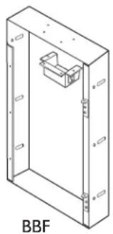
natural_image
Isometric line drawing of a rectangular enclosure with a small internal component, labeled 'BBF' at the bottom (no other text or symbols)
natural_image
Isometric line drawing of a rectangular enclosure with internal components, labeled 'BBS' at the bottom (no other text or symbols)
natural_image
Electronic component with two triangular buttons on a rectangular base (no text or symbols)


- Wall-Mount Power Vector Amplifiers WV100, WV150, & WV250 Models
- Notice
- Important Safety Information
- IMPORTANT
- CAUTION
- RISK OF ELECTRIC SHOCK DO NOT OPEN
- Contents
- PANEL DESCRIPTIONS....2-3
- INSTALLATION ....4
- MODULES ....5
- CONNECTIONS 6-8
- OPERATION 9-10
- BLOCK DIAGRAM ....11
- SPECIFICATIONS 12
- TROUBLESHOOTING 13
- LIMITED WARRANTY......Back Cover
- ACCESSORIES/COMPONENTS ....Back Cover
- Input Volume Control
- Signal / Clip Indicator
- Panel Input Connector
- Output Limiter Control with Indicator
- Average / Peak Switch
- LED Output Level Meter
- Tape Out
- Bass Control
- Treble Control
- Master Volume Control
- Power Switch
- Wall-Mount Power Vector Module Bay (Rear)
- Module Bays
- Lo-Cut Switch
- Tone Control Bypass Switch
- Wall-Mount Power Vector Connector Board (Rear)
- Trans Output / Direct Out Selector
- Speaker Output Barrier Strip
- Mute Control Terminals
- Bridging Mix Bus
- Remote Volume Control Terminals
- Package Contents
- Mounting
- WARNING:
- Front Panel Input Connector
- Module Installation
- - CAUTION - DO NOT FORCE MODULES
- Output Modules
- Functionality
- Input Modules
- Priorities
- Speakers
- Transformer-Coupled Speaker Connections
- 4-Ohm Low-Impedance Speaker Connections
- COM and GND Terminals
- Remote Volume Control
- Mute Control
- Bridging Mix Bus
- System Expansion of Power Vector Amplifiers
- Front Panel Controls & Indicators
- Input Volume Controls
- Signal / Clip Indicator
- Bass and Treble Controls
- Master Volume Control
- Average / Peak Switch & LED Output Meter
- Power Switch / Power Indicator
- Output Limiter
- Rear Panel Controls
- Trans Output / Direct Out Selector Switch
- Other Controls (Located In Module Bay 6)
- Tone Control Bypass Switch
- Lo-Cut Switch
- Specifications
- Frequency Response
- Distortion
- Signal-to-Noise
- Tone Controls
- Output Impedance
- Tape Out
- Limited Warranty; Exclusion of Certain Damages
- Accessories/Components
- Mounting Components
- Accessories
- RVCP - Remote Volume Control Panel
Brand : Bogen
Model : WV100
Category : Hand blender