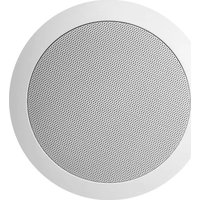
CS75 - Loudspeaker Audac - Free user manual and instructions
Find the device manual for free CS75 Audac in PDF.


| Product Type | Active Bookshelf Speaker |
| Brand | Audac |
| Model | CS75 |
| Dimensions (W x H x D) | 200 mm x 300 mm x 250 mm |
| Weight | 4.5 kg per speaker |
| Power Output | 50 W RMS per channel |
| Frequency Response | 60 Hz - 20 kHz |
| Impedance | 8 ohms |
| Driver Configuration | 1-inch tweeter, 5.25-inch woofer |
| Inputs | Bluetooth, RCA, 3.5mm aux |
| Power Supply | AC 100-240V, 50/60Hz |
| Enclosure Type | Bass reflex with front port |
| Controls | Volume knob, power switch, source selector |
| Recommended Placement | On desktop or shelf, at ear level |
| Cleaning Instructions | Wipe with dry cloth; avoid liquids |
| Safety Features | Overcurrent protection, heat sink |
| Spare Parts Availability | Contact Audac support for drivers or amplifiers |
| Environmental Operating Temperature | 0°C to 40°C |
Frequently Asked Questions - CS75 Audac
User questions about CS75 Audac
0 question about this device. Answer the ones you know or ask your own.
Ask a new question about this device
Download the instructions for your Loudspeaker in PDF format for free! Find your manual CS75 - Audac and take your electronic device back in hand. On this page are published all the documents necessary for the use of your device. CS75 by Audac.
USER MANUAL CS75 Audac
PROFESSIONAL AUDIO EQUIPMENT
Ceiling Speaker CS75
Installation Guide
Installation Procedure
1) Cut a hole in the ceiling on the desired mounting location of the loudspeaker with a diameter of 167 mm. The included cutout template can be used for marking.
2) Provide the loudspeaker connection cable through the mounting hole.
3) Take the loudspeaker, and remove the front grill. The front grill can be removed by rotating the mounting clips outwards and pushing them down. The fixing screws will push the front grill out.

natural_image
Pure mechanical cross-section diagram without any text, numbers, or symbols4) Pull the mounting clips up again, and rotate them inwards, making the speaker fit through the mounting hole in the ceiling.
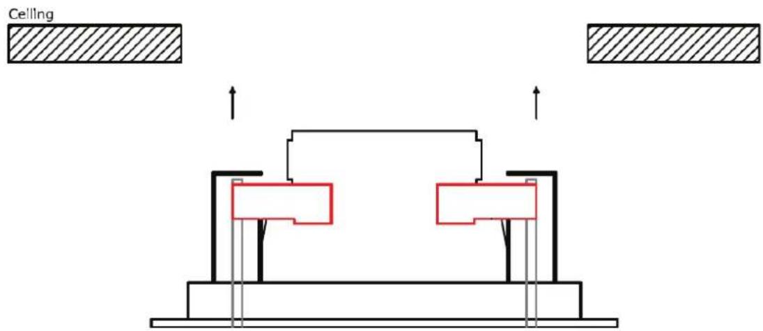
5) Connect the loudspeaker connection cable with the power tap connection block. On this connection block, several connections can be made for different power taps. Depending of the desired power, connections can be made for 8 Ohm low impedance application, or 24 Watt / 12 Watt / 6 Watt for 100 Volt applications.
Press the locking mechanism of the desired power tap down, and insert the connection cable. After releasing the locking mechanism, the speaker connection cable is connected to the loudspeaker or transformer.
Always connect the common of the amplifier output to the C terminal, and the positive amplifier output to the desired terminal. (8 Ω For low impedance applications and the desired power terminal for 100 Volt applications).
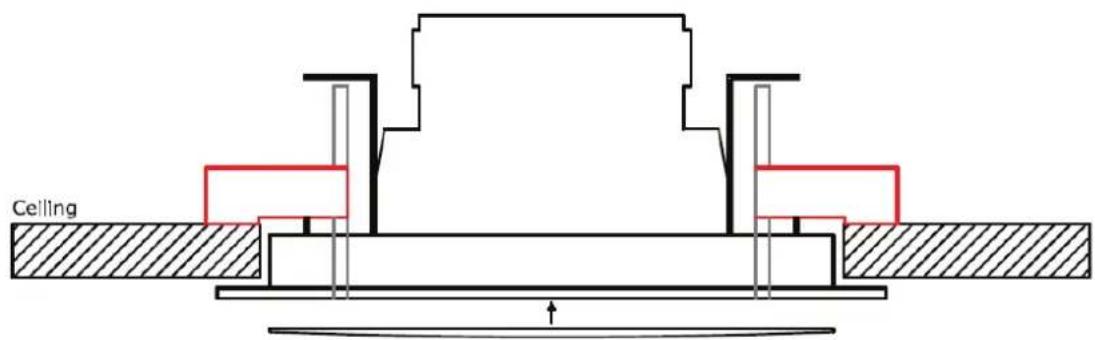
6) Once the connections are made, the loudspeaker can be installed in the provided mounting hole. Insert the speaker in the provided mounting hole, and use a screwdriver for tightening the fixing screws. Once the screws are tightened by a quarter turn, the mounting clip will rotate outwards and will be locked behind the ceiling. From this moment, the loudspeaker cannot fall out the ceiling. To make the speaker equal with the ceiling, the fixing screws should be tightened.

7) Once the mounting screws are tightened, the front grill can be assembled to the loudspeaker. On locations where high vibrations may occur, it is recommended to push the included small rubber pieces into the groove where the grill fits in. This small rubber pieces makes sure that the grill won't come out by vibrations.


Brand : Audac
Model : CS75
Category : Loudspeaker