
SVCA1200ET - Heating SVAN - Free user manual and instructions
Find the device manual for free SVCA1200ET SVAN in PDF.


| Product Type | Fan Heater |
| Model | SVCA1200ET |
| Brand | SVAN |
| Power Consumption | 2000 W |
| Voltage | 220-240 V ~ 50 Hz |
| Heating Settings | 2 levels (1000 W / 2000 W) |
| Fan Only Mode | Yes |
| Thermostat | Adjustable |
| Overheat Protection | Yes |
| Tip-Over Safety Switch | Yes |
| Dimensions (HxWxD) | 25 x 18 x 12 cm |
| Weight | 1.2 kg |
| Material | Plastic |
| Color | White / Black |
| Cord Length | 1.5 m |
| Noise Level | ≤ 45 dB |
| Certification | CE |
| Usage | Indoor only |
Frequently Asked Questions - SVCA1200ET SVAN
User questions about SVCA1200ET SVAN
0 question about this device. Answer the ones you know or ask your own.
Ask a new question about this device
Download the instructions for your Heating in PDF format for free! Find your manual SVCA1200ET - SVAN and take your electronic device back in hand. On this page are published all the documents necessary for the use of your device. SVCA1200ET by SVAN.
USER MANUAL SVCA1200ET SVAN
natural_image
White electronic device with digital display showing temperature reading of 23.8°C, no visible text or symbols on the device itself.SVCA900E7/SVCA1200ET/SVCA1500ET
svan

CASTELLANO:
ÍNDICE:
natural_image
Simple line drawing of a rope hanging from a wall with a cross mark, next to stacked books (no text or symbols)
natural_image
Close-up of two metallic screw fasteners with metal fittings (no text or symbols visible)C

natural_image
Two metallic mechanical components, one with a circular hole and the other rectangular, shown against a plain background (no text or symbols visible)D

natural_image
Four metallic screw fasteners with threaded end caps, shown against a plain background (no text or symbols visible)E

natural_image
Close-up of four metallic screw fasteners on a plain surface (no text or symbols visible)F
natural_image
Mechanical assembly diagram showing a pin alignment and a cylindrical component with internal structure (no text or symbols)Fig. 6 Fig. 7
natural_image
Simple line drawing of a screwdriver touching a surface with a small object nearby (no text or symbols)Fig. 8
natural_image
Illustration of a hand holding a pen next to a rectangular electronic device (no text or symbols visible)Fig. 10
natural_image
Diagram of a screwdriver positioned above a ladder with a falling object (no text or symbols)Fig. 11
2.2 MONTAJE DE PIES:
• MANUAL - MODO CONFORT:

- Para programar “Anti-hielo”, pulse la tecla “Anti-hielo”.
(Modo Anti-hielo = una sola barra abajo indica modo anti-hielo).

General instructions
- Please read the explanatory instructions prior to installation.
- Remove the plug from the mains power socket to disconnect the heater. Do NOT pull on the cable.
- Do not leave the mains cable in contact with the heater when it is switched on.
- During operation, ensure that the heater is kept well away from combustible materials such as curtains, carpets and furniture, etc.
- DO NOT COVER THE HEATER. DO NOT USE IT TO DRY CLOTHES.

If it is covered, there is serious risk of overheating.

- DANGER: If the mains cable is damaged, it must be replaced by the manufacturer or by its after-sales service, by fully qualified personnel in order to prevent any hazardous situations.
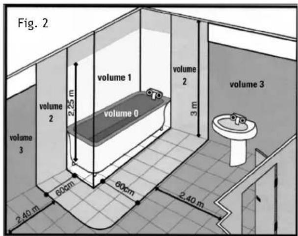
- If the heater is to be installed in a bathroom, it must be positioned so that it cannot be reached by a person in the bath or shower (Figure 2).
- The heater must not be located under or in front of a mains socket.
- When disposing of the heater, all requirements established by current legislation for waste processing and recycling must be followed.
- The installation must be carried out according to current electrical legislation.
- This heater must have an earth connection.
- The heater must be installed so that the mains plug is always accessible.
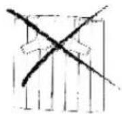
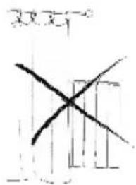
- This heater cannot be flush-mounted in a wall. Always respect the safety distances (Figures 3 and 4).
* A locking system must be fitted to prevent children from playing with the heater programming.
- This heater is not designed to be handled by children or physically, mentally or sensory handicapped persons, with little experience or knowledge, unless under the supervision of a person responsible for their safety and in possession of the corresponding instructions on use. Children must be supervised to ensure they do not play with the heater.
* Children under 3 years must be kept well away from the heater unless under constant supervision.
*Children of less than 3 years should be kept away unless continuously supervised. Children aged from 3 years and less than 8 years shall only switch on/off the appliance provided that it has been placed or installed in its intended normal operating position and thy have been given supervision or instruction concerning use of the appliance in a safe way and understand the hazards involved. Children aged from 3 years and less than 8 years shall not plug in, regulate and clean the appliance or perform user maintenance.
* This appliance may be used by children age 8 and over all by persons with physical, sensorial or mental disabilities or without experience or knowledge, provided they have been duly trained and are supervised by somebody who understands the hazards. The cleaning and maintenance to be carried out by the user must not be done by children. Children should not play with the appliance.

- PRECA UTION: Certain parts of this heater may become very hot during operation and cause burns. Special care must be taken when children and other vulnerable persons are present.

- PRECAUTION: Keep bags and other accessories well out of the reach of children.
- Do not touch the outside of the heater during operation.
- It is quite normal to notice a smell of “something new” when the heater is switched on for the first time”. Allow your heater to work in a well-ventilated location for two or three hours.
- Before each cold season or if the heater has been switched off for several days, it should be cleaned before switching it on (follow the steps in “section 10 Maintenance”). This cleaning will prevent the burning of accumulated dust and other remains.
- Do not use your heater without first fitting the base plinths directly on the floor.
- This heater CANNOT be operated with external programmable units or any other third party control device.
- Owing to the convection effect of this heater, together with other external factors, discolouration of metal and other surfaces can be caused if in proximity to the heater. This can cause discoloration of metal and plastic surfaces.
- Temperature fluctuations may cause crackling or heater noises. This is not an indication of failure.
* The heater warranty does not cover any damage caused by failing to follow these instructions.
2
Installation and mounting
- This heater can be installed on feet (provided) or on a wall.
- The heater must never be installed underneath a mains wall socket.
- The heater must never be installed in a position where the switches and other controls can be reached by someone in the bath or shower.
- The heater works through natural air convection. In order to achieve correct performance and uniform heat distribution, when it is installed on a wall the lower part of the heater must be at a minimum distance of twenty centimetres from the floor and a minimum distance of twenty centimetres from the sides and fifty centimetres from an upper shelf and also a minimum distance of twenty centimetres from any wall or object (furniture and curtains etc).
IMPORTANT

natural_image
Simple line drawing of a 3D cube with intersecting lines, labeled Fig. 1 (no text or symbols on the diagram itself)

natural_image
Gray circular warning symbol with an exclamation mark in the center (no text or numbers)You can install your heater in volume 3 in the bathroom. It must not be possible to reach it from the bath or shower.
2.1 WALL INSTALLATION:
- Select a suitable location on the wall, which should be firm and level. Check that there is a mains socket close by.
- The distances marked, "a" and "e" vary depending on the heater model.
Safety distances and installation
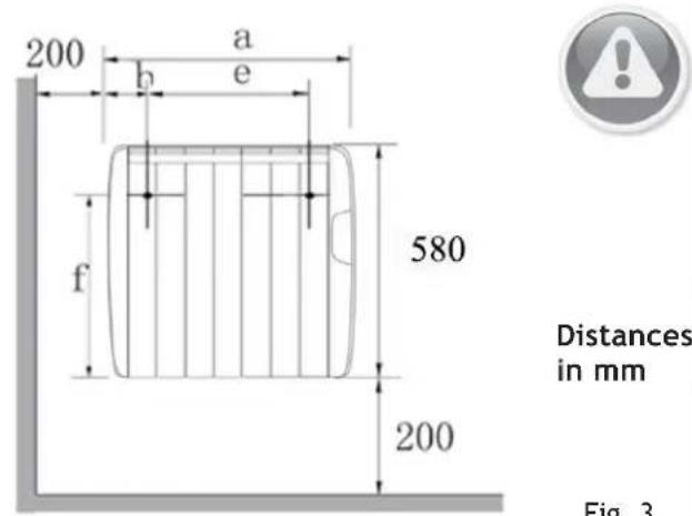
Fig. 3
| Models | a (mm) | b (mm) | e (mm) | f (mm) |
SVCA900ET 550 93 280 495
SVCA1200ET 690 93 420 495
SVCA1500ET 830 93 560 495

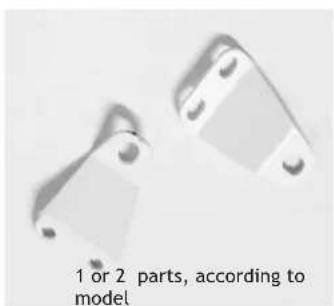
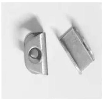
- Open the package box and check that all accessories are present.
B
A
natural_image
Two metallic bracket components with mounting holes, labeled '1 or 2 parts, according to model' (text is minimal and not part of the image content)
natural_image
Close-up of two metallic screw fasteners with threaded ends (no text or symbols visible)C
natural_image
Two metallic mechanical components with circular holes, shown from different angles (no text or symbols visible)D

natural_image
Four metallic screw fasteners with threaded end caps, shown against a plain background (no text or symbols visible)E

natural_image
Close-up of four metallic screw fasteners on a plain surface (no text or symbols visible)F

natural_image
Close-up of metallic screw fasteners with visible screws, no text or symbols present4. ASSEMBLY
4.1 While respecting the previously indicated safety measurements, make two marks on the wall according to measurement "e" indicated in Table 1 and at a height of 695mm from the floor (not the skirting board).

Fig. 5 Fig. 10
4.2 Drill two 10-mm diameter holes, with a minimum length of 60 mm at the wall marks.
4.3 Screw the hooks (C) into the two holes, with the two screws and two plugs (D).

natural_image
Mechanical assembly diagram showing a pin inserted into a bracket with a cylindrical component and intersecting lines (no text or symbols)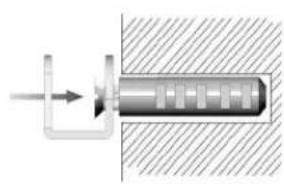
natural_image
Pure mechanical diagram showing a piston-cranked shaft inserted into a housing, with no text or symbols present.Fig. 6
Fig. 7
4.4 Screw the two brackets (A) (or one support, depending on model) to the rear part of the heater with the four screws (E) (or two screws, depending on model).
Note: The two brackets (A) are screwed to the holes located on the lower rear part, at both ends.

natural_image
Simple line drawing of a screwdriver striking a small object on a surface (no text or symbols)Fig. 8
4.5 Hang the heater on the two hooks (C) on the wall. Ensure that the heater is correctly secured on both hooks.

Fig. 9
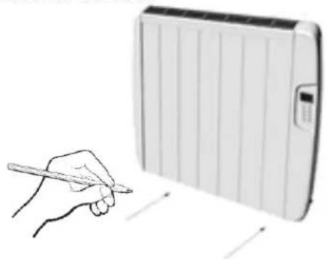
4.6 When the heater is fitted in place, make two marks on the wall at the two brackets (A) to ensure the heater is fixed to the wall:
natural_image
Illustration of a hand holding a pen next to a rectangular electronic device with a screen (no text or symbols visible)4.7 Drill two 4-mm diameter holes, with a minimum depth of 25 mm at the two marks on the wall.
4.8 Use the two screws and two plugs B) to completely secure the heater to the wall.

natural_image
Diagram of a mechanical setup with a tool and two vertical rods, no text or symbols presentFig. 11
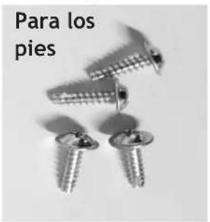
2.2 INSTALLING THE FEET:
- Screw the two feet to the lower rear part of the heater with the four screws (F).

Control panel
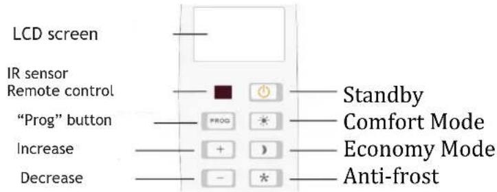
4 LCD screen
Fig. 13
The screen comes on for ten seconds every time a button is pressed.

(1)CONSUMPTION INDICATOR
This appears when the heater is consuming power, in other words, in operation.
(2) TEMPERATURE INDICATOR:
- Ambient temperature: that of the room, it is displayed on all screens by default.
- Assigned temperature: that selected by the user as the desired temperature for COMFORTMODE, ECONOMY MODE OR ANTI-FROST MODE. To display this temperature press the (-) or (+) button.
5
Operation
- Your heater is fitted with a digital, daily-programmable timer-thermostat that controls and adjusts the heating.
- The heater can be used to two ways, either manually or automatically. It is fitted with a daily timer for each day of the week.
IMPORTANT:
The temperature indicated on the screen may differ from that given by another thermometer in the same room. Different conditions such as air currents, windows etc, could cause these differences.
5.1 Putting into operation
1) When the heater is installed and connected to the mains power, press the ON/ OFF switch, which is located at the right rear part of the unit.
2) The LCD screen will light up and all the symbols will flash several times.
3) Then the operating mode just before the last switch-off appears (stand-by, manual or automatic), together with the approximate room temperature.
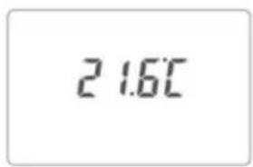
Standby Mode
Fig. 15
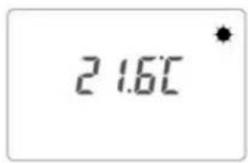
Manual Mode
(example: Comfort Mode)
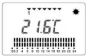
Fig. 16
Automatic Mode
Fig. 17
4) When in "Standby" mode (Fig. 15), press the "Standby" button to switch the heater on (Figure 13). The heater comes on and the last selected operating mode symbol appears on the screen. In addition, the approximate room temperature is displayed.
If the heater is switched on in manual (Fig. 16) or automatic mode (Fig. 17) the unit is already in operation.
5.2 Locking / Unlocking

The heater controls will automatically lock when no button has been pressed for sixty seconds.
This operation will occur in both manual and automatic modes.
The heater controls can be unlocked by pressing the "+" and "-" buttons on the control panel for three seconds (Figure 13) or on the remote control.
Note: After unlocking the keypad, the selected temperature will appear for three seconds with ^ C flashing.
5.3 Using the heater
The heater can operate in manual or automatic mode (programmed).
5.4 Manual Use
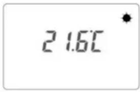
To select manual mode, press the "PROG" key until the time bands disappear from the LCD screen (Figure 18).
Manual Mode (example: Comfort Mode)
Fig. 18
When in manual mode, the desired heating mode can be selected (comfort, economy or anti-freeze) by pressing the corresponding button (Fig. 13) and the heater will permanently operate in any of these modes with the assigned temperatures.
5.5 Changing the selected temperature
The heater is supplied with a pre-established temperature for each operating mode, which can be modified in the following manner:
• MANUAL - COMFORT MODE:

a) Press the Comfort mode button (Figure 13).
b) Use the (-) or (+) buttons to select the desired temperature. (Example, select 22 °C)
c) The selected temperature is saved.
The existing room temperature will be displayed again after a few seconds.
Note: The comfort mode is recommended for a comfortable temperature when remaining in the room.
Recommended temperature: 21 °C.
- MANUAL - ECONOMY MODE:
a) Press the Economy Mode button (Figure 13).
b) Use the (-) or (+) buttons to select the desired temperature. (Example, Select 18 °C)
c) The selected temperature is saved.
The existing room temperature will be displayed again after a few seconds.
Note: This mode is recommended for long absences from the room and is the ideal temperature for nighttime.
Recommended temperature: 17 °C.
• MANUAL - ANTI-FREEZING MODE:

a) Press the Anti-freezing Mode button (Figure 13).
b) Use the (-) or (+) buttons to select the desired temperature. (Example, Select 7 °C)
c) The selected temperature is saved.
The existing room temperature will be displayed again after a few seconds.
Note: This mode is recommended for unused dwellings in extremely cold climates.
Recommended temperature: 5 °C.
IMPORTANT: If the selected temperature is higher than that of the room the heater will start operating (the flame symbol will be displayed 🎨).
Note: If, no buttons are pressed after approximately ten seconds the screen will be switched off. It will be switched on again when any button is pressed.
5.6 Switching off
The heater operation can be disconnected by pressing the “Standby” button (Fig. 13).

Stand By Mode
Fig. 19
The heater can be permanently switched by the ON/OFF switch at the rear of the unit.
5.7 Automatic Use (Programmed)
Taking into account your personal needs, the heater provides the possibility to create an individual programme.
This programme is established according to the day, time and operating modes: comfort, economy, anti-icing or standby mode.
1) If the heater is in Standby (Fig.18), press the "Standby" button to switch it on.

Standby Mode
Fig. 20
2) Press the "PROG" button for three seconds. The four clock digits will be displayed.
First, the two "hour" digits will flash. Use the (+) or (-) buttons to enter the current hour.
Then, press "PROG" to programme the minutes. Enter the current minutes. Press the "PROG" button.
3) Then, programme the current day of the week. All the following digits will be displayed, “1, 2, 3, 4, 5, 6, 7”.
Use the (+) or (-) buttons to enter the day of the week as follows (1 = Monday, 2 = Tuesday etc).
Press the "PROG" button.
4) Programming each day of the week.
Begin by programming the first band for Monday (1) From 00:00 hours until 01:00 (the first bands will flash).
An operating mode can be assigned to each hour:
- To programme comfort, press the "Comfort" button:
(Comfort Mode = one double bar).

Fig. 21
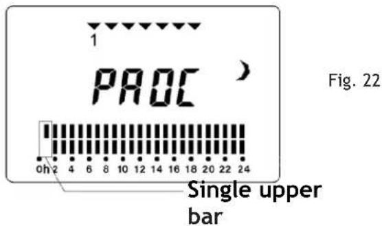
- To programme economy, press the “Economy” button
(Economy Mode = one single upper bar).
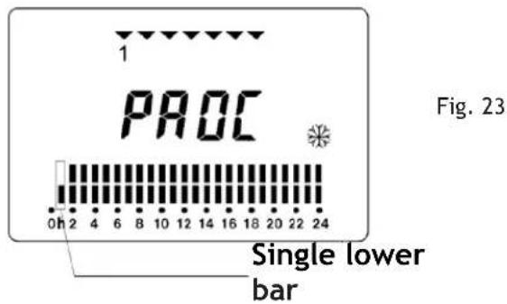
- To programme "Anti-icing", press the "Anti-icing" button.
(Anti-icing Mode = one single upper bar).
- To programme "Standby - switch off", press the "Stand-by" button.
Standby Mode = no bars".

Programming is performed hour by hour. The selected hour will flash.
6) Press the “+” button to select the following time band. Repeat the heating mode selection process as required.
Press the “-” button to return to the previous time band.
7) When all the time bands for Monday have been programmed, press the "PROG" button to move on to the next day, Tuesday.
Repeat all these steps to programme each day of the week, until Sunday (7) is reached. When Sunday is programmed, press the “PROG” button to confirm. The programming mode screen will be displayed containing the updated values.
IMPORTANT: If you wish to modify the previously assigned temperatures for each operating mode then follow the steps given in section 5.5 of these instructions.
EXAMPLE PROGRAMME:

Fig. 25
• The programmed actual day. (1 Monday).
- The approximate room temperature (Example 21.6 °C).
• The current time band flashes (17:00 - 18:00). - The mode programmed in each time band: Comfort Mode (sun).
- The heater element is switched on ..... Note: If this symbol is not shown, the heater is not consuming power.
IMPORTANT:
Pressing the "PROG" button will change between manual and automatic modes (programmed).
Note: After working for two or three months, the clock will usually require adjustment.
6
FAQ
I. If the unit does not heat:
a. Verify that it is switched on.
b. Check that the power consumption indicator is on; otherwise, increase the temperature assigned to each mode.
II. If the unit does not provide sufficient heat:
a. Check whether the flame symbol is displayed and if it appears intermittently, increase the temperature assigned to each mode.
b. Check that the installed heater has adequate
7
Power cuts
If there is a power cut, the heater will not work, but will be switched on again in the same mode as before when the power is re-established.
All previous adjustments will remain unaltered (temperatures and programmes), "EXCEPT THE CLOCK AND THE CURRENT DAY OF THE WEEK".
If, during an absence from your dwelling, you discover that the heaters are not working:
When the mains power has been restored, the clock and current time must be reprogrammed.
power for the room size.
8
Safety
- Do NOT cover the heater. Do NOT use it to dry clothes. If it is covered, there will be a serious risk of overheating.
- The unit is fitted with a safety device that will switch it off in case of overheating. It will automatically switch on again when the problem is resolved. If this problem repeats itself it could cause damage or faults that are not covered by the warranty.
9
Recommendations
- Remember that the economy mode should be used when there is nobody in the room or at night. The comfort mode provides the desired temperature when the room is occupied.
- The anti-frost mode should not be used unless in an extremely cold climate.
• Always remember to maintain intermediate temperatures and extremely high or low values should not be established.
10
Maintenance
- This heater does not require any special maintenance.
- It is recommended that when the heater is put into use for the first time each year, all dust and any other dirt on the outer surfaces should be cleaned off (ALWAYS COLD AND SWITCHED OFF), together with any accumulated dust inside.
- The dust should be cleaned off with a soft dry cloth. ALWAYS WITH THE HEATER SWITCHED OFF AND COLD.
- NEVER USE SOLVENTS, CLEANING OR ABRASIVE PRODUCTS.
svan
| REF. W | N° | 230 V50 HZCLASE ICLASSE 1CLASS 1 | |
| SVCA900ET | 900 6 | ||
| SVCA1200ET | 1200 8 | ||
| SVCA1500ET | 1500 10 | ||


- svan
- CASTELLANO:
- ÍNDICE:
- MONTAJE DE PIES:
- • MANUAL - MODO CONFORT:
- General instructions
- 2
- Installation and mounting
- WALL INSTALLATION:
- ASSEMBLY
- INSTALLING THE FEET:
- (1)CONSUMPTION INDICATOR
- TEMPERATURE INDICATOR:
- 5
- Operation
- IMPORTANT:
- Putting into operation
- Locking / Unlocking
- Using the heater
- Manual Use
- Changing the selected temperature
- • MANUAL - COMFORT MODE:
- - MANUAL - ECONOMY MODE:
- • MANUAL - ANTI-FREEZING MODE:
- Switching off
- Automatic Use (Programmed)
- 6
- FAQ
- 7
- Power cuts
- 8
- Safety
- 9
- Recommendations
- 10
- Maintenance
Brand : SVAN
Model : SVCA1200ET
Category : Heating