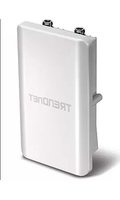
TEW-739APBO - Access Point TRENDNET - Free user manual and instructions
Find the device manual for free TEW-739APBO TRENDNET in PDF.


| Product Type | N300 Outdoor PoE Access Point |
| Wireless Standard | IEEE 802.11n/g/b |
| Frequency Band | 2.4 GHz |
| Maximum Data Rate | 300 Mbps |
| Interface | 1 x PoE port (proprietary) |
| Power Supply | 48 V DC, 0.5 A (via included PoE injector) |
| Power over Ethernet | Proprietary PoE (injector included) |
| Outdoor Rating | IP67 (aluminum housing) |
| Mounting | Wall and pole mount hardware included |
| Antenna Connector | 2 x N-Type female (antennas sold separately) |
| Operating Modes | Access Point (AP), WDS, Repeater, CPE + AP |
| Wireless Security | WEP, WPA-PSK, WPA2-PSK, WPA-Enterprise, WPA2-Enterprise, 802.1X |
| Multiple SSIDs | Up to 8 (1 primary + 7 virtual) |
| QoS | WMM (Wi-Fi Multimedia) |
| Management | Web-based GUI, SNMP v2c/v3, Telnet, SSH |
| Dimensions (approx.) | 200 x 150 x 50 mm (without antennas) |
| Weight (approx.) | 1 kg (including mounting bracket) |
| Package Contents | TEW-739APBO, PoE injector, power adapter, mounting hardware, grounding wire, CD-ROM, quick installation guide |
| Range | Up to 4 km (2.5 miles) with optional TEW-OA57 antennas |
| LED Indicators | PWR, WAN, LAN, WLAN (3 levels) |
| Reset Button | Reboot (2 sec) or Factory Reset (>10 sec) |
Frequently Asked Questions - TEW-739APBO TRENDNET
User questions about TEW-739APBO TRENDNET
0 question about this device. Answer the ones you know or ask your own.
Ask a new question about this device
Download the instructions for your Access Point in PDF format for free! Find your manual TEW-739APBO - TRENDNET and take your electronic device back in hand. On this page are published all the documents necessary for the use of your device. TEW-739APBO by TRENDNET.
USER MANUAL TEW-739APBO TRENDNET
N300 Outdoor PoE Access Point
TEW-738APBO
TRENDnet User's Guide
Table of Contents
Contents
Introduction....4
Package Contents 5
Hardware Feature 5
Product Benefit....7
Installation Considerations 7
Installation 8
Configuration....9
Applications 9
AP Mode (including Access Point + WDS) 9
WDS Mode (Pure WDS) 10
Client Bridge + Universal Repeater Mode 11
CPE + AP Mode (Router Client + Access Point) 11
Web Management Interface Instructions....12
AP Mode Configuration....12
External Network Connection.... 12
Network Requirement 12
Configure LAN IP 13
Wireless LAN Network 15
Wireless General Setup.... 15
Wireless Advanced Setup.... 15
Wireless WMM QoS Setup....17
Create Virtual AP (VAP)....19
Virtual AP Setup 20
Wireless MAC Filter Setup....22
Wireless Network Expansion 22
System Status 23
System Overview....23
Associated Clients Status 24
Show WDS Link Status.... 24
Extra Information 25
Event Log 26
WDS Mode Configuration....26
External Network Connection 26
Network Requirement 26
Configure LAN IP 27
Wireless Network Expansion 27
Wireless General Setup.... 27
Wireless Advanced Setup....28
Wireless WMM QoS Setup.... 29
WDS Setup 31
System Status 32
System Overview 32
Extra Information.... 33
Event Log....34
WDS Link Status 34
Repeater Mode 35
External Network Connection 35
Network Requirement 35
Configure LAN IP 35
Wireless Network Expansion 36
Wireless General Setup.... 36
Wireless Advanced Setup....37
Wireless WMM QoS Setup.... 39
Site Survey 40
Repeater AP Setup 41
Wireless MAC Filter Setup 43
Create Wireless Profile 43
Bandwidth Control....45
Configure SNMP Setup.... 45
Configure Time Policy 46
System Status 47
System Overview 47
DHCP Client 48
TRENDnet User's Guide
Table of Contents
Extra Information 48
Event Log 49
Associated Client List 49
Remote AP status....50
CPE + AP Mode Configuration ....50
External Network Connection....50
Network Requirement 50
Configure CPE Setup....51
Configure DDNS Setup 52
Configure LAN IP 53
Configure Static IP address 54
Access Point Association....54
Wireless General Setup 54
Wireless Advanced Setup....55
Wireless WMM QoS Setup 56
Site Survey....58
Create Wireless Profile....58
AP Setup 60
Wireless AP MAC Filter Setup 62
Access Control 62
DMZ 62
IP Filter Setup....63
MAC Filter Setup 63
Virtual Server 64
Bandwidth Control 64
Routing....65
Status 65
System Overview....65
DHCP Client 66
Extra Information....67
Event Log....68
Associated Client List 68
Remote AP status....68
System Management 68
Configure Management....68
Configure System Time 70
Configure SNMP Setup....70
Enable UPNP 71
Backup / Restore and Reset to Factory....71
Firmware Upgrade 72
Network Utility 72
Reboot....73
Mounting bracket installation....73
Package contents....73
Wall mount bracket....74
Pole mount bracket 74
Appendix....75
Windows TCP/IP Settings 75
Enabling UPnP in Windows XP....76
Limited Warranty....78
TRENDnet User's Guide
TEW-739APBO
Introduction
TRENDnet's N300 Outdoor PoE Access Point, model TEW-739APBO, provides blanket outdoor Wireless N300 connectivity for distances of up to 4 km (2.5 miles)*. A variety of installation scenarios are facilitated with Access Point (AP), Wireless Distribution System (WDS), Repeater, and CPE + AP modes. The rugged aluminum IP67 rated housing comes with wall and pole mounting hardware. Antennas, sold separately, are required in order to function*.
Performance
Antennas
Antennas, sold separately, are required in order to function
Multi-Mode Support
Supports Access Point (AP), Wireless Distribution System (WDS), Repeater, and CPE + AP modes
N300 Wireless (2.4 GHz)
Compliant with 802.11n/g/b technology (2.4 GHz) with data rates up to 300 Mbps
Outdoor Rated
Durable aluminum enclosure with an IP67 outdoor weather rating
Distance Rating
Rated for distances of up to 4 km (2.5 miles)* (with TEW-OA57 antennas sold separately)
Power over Ethernet (PoE)
Comes with a proprietary PoE injector, so that it can connect a regular non-PoE switch
Logs
Real time logs and statistics help troubleshooting
Encrypted Wireless
Support for wireless encryption of up to WPA2
Multiple SSIDs
Create up to seven additional SSIDs
Compatibility
Compatible with legacy wireless devices
Mounting Hardware
Pole and wall mounting hardware included
* Effective wireless coverage may vary depending on the wireless device's output power, antenna gain, antenna alignment, receiving sensitivity, and radio interference. Additionally environmental factors such as weather conditions, physical obstacles, and other considerations may affect performance. For optimal results, we recommended consulting a professional installer for site survey, safety precautions, and proper installation.
**Recommended max. PoE cable length of 70 m
TRENDnet User's Guide
TEW-739APBO
Package Contents
The standard package contents
- TEW-739APBO
• CD-ROM (User's Guide)
• Multi-Language Quick Installation Guide - Mounting hardware
• Proprietary PoE injector
• Water-proof RJ-45 plug (Network cable not included)
• Power adapter (48 V, 0.5 A) - Grounding wire
Hardware Feature
Front Panel
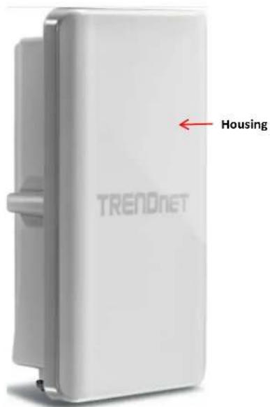
• Housing: IP 66/67 housing
Bottom Panel
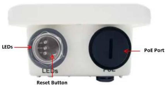
• LEDs
o PWR: Indicates the unit is powered on.
o WAN: Turns on when CPE mode is used and indicates WAN connection
○ LAN: Turns on when there is a LAN connection and blinks when data is running through the LAN port.
○ WLAN (LED1-3): Turns on when wireless is enabled and blinks during wireless transmission occur. Also indicates connection rate; LED1 (best), LED2 (better) and LED3 (good)
- Reset Button (unscrew cap)
- Reboot: Press and hold the reset button for 2 seconds to restart the unit. All LEDs except PWR will turn off before the unit turns back on and wireless transmission occur.
- Reset – Press and hold the reset button for more than 10 seconds to restore the unit back to factory default settings.
- PoE Port (unscrew cap): Connect the network cable that is connected to the provided PoE injector to power and configure the unit.
Rear Panel
Antenna N-Type Connector

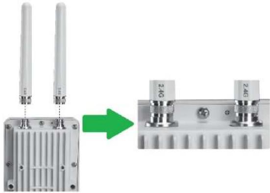
- Antenna N-Type Connector: Female N-Type Connector fits any standard antenna with Male N-Type connection
- Grounding point: Connect the provided grounding cable to securely ground the access point.
TRENDnet User's Guide
TEW-739APBO
Product Benefit
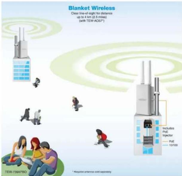
The N300 Outdoor PoE Access Point is the point of connection to wireless outdoor networks for service providers deploying services to business or residential broadband subscribers. Network administrators can create multiple subscriber service tier using per-subscriber rate limiting features, and manage centrally.
Installation Considerations
There are a number of factors that can impact the range of wireless devices.
- Adjust your wireless devices so that the signal is traveling in a straight path, rather than at an angle. The more material the signal has to pass through the more signal you will lose.
- Keep the number of obstructions to a minimum. Each obstruction can reduce the range of a wireless device. Position the wireless devices in a manner that will minimize the amount of obstructions between them.
- Building materials can have a large impact on your wireless signal. In an indoor environment, try to position the wireless devices so that the signal passes through less dense material such as dry wall. Dense materials like metal, solid wood, glass or even furniture may block or degrade the signal.
- Antenna orientation can also have a large impact on your wireless signal. Use the wireless adapter's site survey tool to determine the best antenna orientation for your wireless devices.
- Interference from devices that produce RF (radio frequency) noise can also impact your signal. Position your wireless devices away from anything that generates RF noise, such as microwaves, radios and baby monitors.
If you are still experiencing low or no signal consider repositioning the wireless devices or installing additional access points. The use of higher gain antennas may also provide the necessary coverage depending on the environment.
TRENDnet User's Guide
TEW-739APBO
Installation
- Unscrew the black cap covering the PoE port of the TEW-739APBO
- Install the waterproof kit and insert one end of an Ethernet cable through the kit.

- Connect the Ethernet cable to the PoE port of the TEW-739APBO
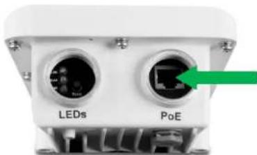
- Tighten and secure the seal nut of the waterproof kit.
- Connect the other end of the Ethernet cable to the P+DATA Out port on the PoE injector.

- Using another Ethernet cable, connect one end to the DATA IN port of the injector.
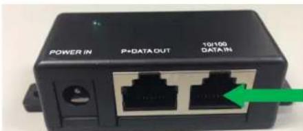
- Connect the other end of the Ethernet cable to the LAN port of your network.
- Plug the power cord into the injector. Then connect the plug into a power outlet.
- Connect and firmly screw your antenna to the N-Type connection port of the TEW-739APBO located on the top panel.
TRENDnet User's Guide
TEW-739APBO
Configuration
- Open a web browser, type the IP address of the Access Point and then press Enter. The default IP address is 192.168.10.100.

- Enter the Username and Password and click OK. By default the Username: root and Password: root.
- Click the Wizard button and follow the setup wizard instructions. Click Finish to complete installation.
Applications
TEW-739APBO is multiple mode system which can be configured either as a wireless gateway or an access point as desired. It also can be used as a WDS link for Ethernet network expansion. This section depicts different applications on Router AP Mode, AP Mode, WDS Mode, CPE Mode, Client Bridge + Universal Repeater Mode and CPE + AP Mode.
Operating Mode
AP Mode
WDS Mode
- Repeater Mode
CPE + AP
AP Mode (including Access Point + WDS)
An access point can be either a main, relay or remote base station. A main base station is typically connected to a wired network via the Ethernet port. A relay base station relays data between main base stations and relay stations or remote base stations with clients. A remote base station is the end point to accept connections from wireless clients and pass data upwards to a network wirelessly.
Example 1: Access Point without WDS
- It can be deployed as a tradition fixed wireless Access Point
![graph LR A["Cloud"] --> B["Routers"] B --> C["Server"] C --> D["Laptop"] style A fill:#fff,stroke:#000 style B fill:#fff,stroke:#000 style C fill:#fff,stroke:#000 style D fill:#fff,stroke:#000](/content/2026/05/1078382/images/36936ff7eaa219e824b9d5efd6109a5cba49537c32ac19c2f7c0ed5c936ae4f0.jpg)
TRENDnet User's Guide
TEW-739APBO
Example 2: Access Point with WDS
- It can be deployed as a tradition fixed wireless Access Point and provides WDS link to expand network
![graph LR A["Cloud"] --> B["Server"] B --> C["Main WDS"] C --> D["Remote"] D --> E["Laptop"] D --> F["Laptop"] D --> G["Laptop"] style A fill:#fff,stroke:#333 style B fill:#fff,stroke:#333 style C fill:#fff,stroke:#333 style D fill:#fff,stroke:#333 style E fill:#fff,stroke:#333 style F fill:#fff,stro…](/content/2026/05/1078382/images/b05ad4f5b408036b20c4a0e6b3f87d1f883611732c7cf96a71664cc38a4a8fd3.jpg)
![graph LR A["Cloud"] --> B["Server"] B --> C["Main"] D["Remote"] --> E["WDS"] E --> C C --> F["Laptop"]](/content/2026/05/1078382/images/9d9a501284c69ea58c96758726b7d08c4f5e430129bb97cc2dac18f010165f52.jpg)
WDS Mode (Pure WDS)
An access point can be either a main, relay or remote base station. A main base station is typically connected to a wired network via the Ethernet port. A relay base station relays data between main base stations and relay stations or remote base stations with clients. A remote base station is the end point to accept connections from wireless clients and pass data upwards to a network wirelessly. In this mode, it can support single or multiple WDS links and no wireless clients can associate with it.
Example 1: Point-to-Point
![graph LR A["Cloud"] --> B["Desktop"] B --> C["WDS"] C --> D["Main"] D --> E["Laptop"] D --> F["Computer"] style A fill:#fff,stroke:#000 style B fill:#fff,stroke:#000 style C fill:#fff,stroke:#000 style D fill:#fff,stroke:#000 style E fill:#fff,stroke:#000 style F fill:#fff,stroke:#000](/content/2026/05/1078382/images/ff8852cb7f36320bacb4ab4ff269d6e8300c042dea41c963f79c62ee7d4e46e8.jpg)
Example 2: Point-to-Multi-Point
![graph LR A["Cloud"] --> B["Server"] B --> C["Desktop"] C --> D["Desktop"] D --> E["Desktop"] E --> F["Laptop"] E --> G["Laptop"] E --> H["Laptop"] C --> I["Wireless Signal"] I --> J["Wireless Signal"] J --> K["Wireless Signal"] K --> L["Wireless Signal"] L --> M["Wireless Signal"] M --> N["Wireless…](/content/2026/05/1078382/images/342ca82fbf968acd99f9a1d605db756b7739b244e6c37b360c06475631405ec4.jpg)
TRENDnet User's Guide
TEW-739APBO
Example 3: Multi-Point Repeating bridge
![graph LR A["Inter"] --> B["Main Base Station"] B --> C["WIFI WAN"] C --> D["LAN"] D --> E["Computer"] D --> F["Computer"] D --> G["Computer"] style A fill:#fff,stroke:#333 style B fill:#fff,stroke:#333 style C fill:#fff,stroke:#333 style D fill:#fff,stroke:#333 style E fill:#fff,stroke:#333 style F…](/content/2026/05/1078382/images/cc8377ac12dcf2ef3976eea911c24baa4ce3002968cdccb94b284fd411053674.jpg)
Client Bridge + Universal Repeater Mode
It can be used as an Client Bridge + Universal Repeater to receive wireless signal over last mile applications, helping WISPs deliver wireless broadband Internet service to new residential and business customers. In this mode, TEW-739APBO is enabled with DHCP Server functions. The wired clients of TEW-739APBO are in the same subnet from Main Base Station and it accepts wireless connections from client devices.

CPE + AP Mode (Router Client + Access Point)
It can be used as an Outdoor Customer Premised Equipment (CPE) to receive wireless signal over the last mile, helping WISPs deliver wireless broadband Internet service to new residential and business customers. In this mode, the TEW-739APBO is a gateway with NAT and DHCP Server functions. The wireless and wired clients of TEW-739APBO are on the different subnet from Main Base Station and it accepts wireless connections from client devices.
![graph LR A["Cloud"] --> B["Server"] B --> C["Network"] C --> D["Laptop"] C --> E["Laptop"] C --> F["Laptop"] style A fill:#fff,stroke:#333 style B fill:#fff,stroke:#333 style C fill:#fff,stroke:#333 style D fill:#fff,stroke:#333 style E fill:#fff,stroke:#333 style F fill:#fff,stroke:#333](/content/2026/05/1078382/images/840499283a3b326ab00b0aa78966acad028998fd886f6a09af5861857b515699.jpg)
TRENDnet User's Guide
TEW-739APBO
Web Management Interface Instructions
TEW-739APBO supports web-based configuration. Upon the completion of hardware installation, TEW-739APBO can be configured through a PC/NB by using its web browser such as Internet Explorer version 6.0.
- Default IP Address: 192.168.10.100
- Default IP Netmask : 255.255.255.0
- Default User Name and Password : admin/admin
Step
- IP Segment Set-up for Administrator's PC/NB: Set the IP segment of the administrator's computer to be in the same range as TEW-739APBO for accessing the system. Do not duplicate the IP Address used here with IP Address of TEW-739APBO or any other device within the network
Example of Segment:
The valid range is 1 \~ 254 and 192.168.10.254 shall be avoided because it is already assigned to TEW-739APBO. 192.168.10.10 is used in the example below.
- IP Address : 192.168.10.10
○ IP Netmask : 255.255.255.0
Launch web browser to access the web management interface of system by entering the default IP Address, http://192.168.10.100, in the URL field, and then press Enter.
- System Login: The system manager Login Page then appears.
Enter "admin" as User name and "admin" as Password, and then click OK to login to the system; the root manager account is used as an example here.
- Login Success: System Overview page will appear after successful login.
AP Mode Configuration
When AP mode is chosen, the system can be configured as an Access Point. This section provides detailed explanation for users to configure in the AP mode with help of illustrations. In the AP mode, functions listed in the table below are also available from the Web-based GUI interface.
External Network Connection
Network Requirement
Normally, TEW-739APBO connects to a wired LAN and provides a wireless connection point to associate with wireless client as shown in Figure 3-1. Then, Wireless clients could access to LAN or Internet by associating themselves with TEW-739APBO set in AP mode.
![graph LR A["Cloud"] --> B["Server"] B --> C["Laptop"] style A fill:#fff,stroke:#000 style B fill:#fff,stroke:#000 style C fill:#fff,stroke:#000](/content/2026/05/1078382/images/b3109e62aa46ed0b033299c52c6faeaeb77cc5cb0fb6a4eac8e0e790d1bdeb15.jpg)
TRENDnet User's Guide
TEW-739APBO
Configure LAN IP
Here are the instructions to setup the local IP Address and Netmask. Please click on System -> LAN and follow the below setting.
- Mode: Check either "Static IP" or "Dynamic IP" button as desired to set up the system IP of LAN port.
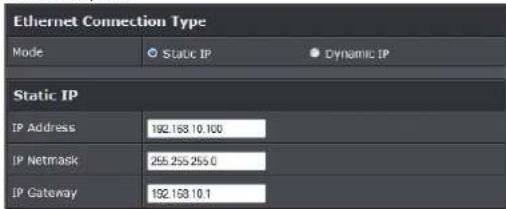
- Static IP: The administrator can manually setup the LAN IP address when static IP is available/ preferred.
- IP Address : The IP address of the LAN port; default IP address is 192.168.2.254
- IP Netmask : The Subnet mask of the LAN port; default Netmask is 255.255.255.0
- IP Gateway : The default gateway of the LAN port; default Gateway is 192.168.2.1
- Dynamic IP: This configuration type is applicable when the TEW-739APBO is connected to a network with the presence of a DHCP server; all related IP information will be provided by the DHCP server automatically.

○ Hostname : The Hostname of the LAN port
- DNS: Check either "No Default DNS Server" or "Specify DNS Server IP" button as desired to set up the system DNS.

o Primary: The IP address of the primary DNS server.
- Secondary: The IP address of the secondary DNS server.
• 802.1d Spanning Tree

The spanning tree network protocol provides a loop free topology for a bridged LAN between LAN interface and 4 WDS interfaces from wds0 to wds3. The Spanning Tree Protocol, which is also referred to as STP, is defined in the IEEE Standard 802.1d. The Spanning tree option is enabled by default on TEW-739APBO. Below Figures depict a loop for a bridged LAN between LAN and WDS link
Click Save button to save your changes. Click Reboot button to activate your changes
TRENDnet User's Guide
TEW-739APBO
![graph TD A["Cloud"] --> B["Server"] B --> C["Remote Base Station"] C --> D["Computer"] C --> E["Laptop"] C --> F["Laptop"] C --> G["Laptop"] C --> H["Remote Base Station"] H --> I["Remote Base Station"] I --> J["Remote Base Station"] J --> K["Remote Base Station"] K --> L["Remote Base Station"] L --…](/content/2026/05/1078382/images/2facdfcf3c74fce925fcb5af8e7d11c7bd4fdfc42930a3d4a4bc57a6a98e3576.jpg)
![graph TD A["Cloud"] --> B["Server"] B --> C["Base Station"] C --> D["Remote Base Station"] D --> E["Remote Base Station"] E --> F["Computer"] E --> G["Computer"] E --> H["Computer"] E --> I["Computer"] D --> J["Loop"] J --> K["WDS"] K --> L["Remote Base Station"] L --> M["Remote Base Station"] M -->…](/content/2026/05/1078382/images/b66a9994f0ebf858d19971001473a883ff5af78e58f60e30c449457453e4142d.jpg)
TRENDnet User's Guide
TEW-739APBO
Wireless LAN Network
The network manager can configure related wireless settings, General Settings, Advanced Settings, Virtual AP (VAP) Setting, Security Settings and MAC Filter Settings.
Wireless General Setup
The administrator can change the data transmission, channel and output power settings for the system. Please click on Wireless -> General Setup and follow the below setting.
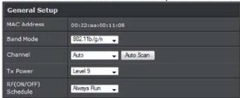
• MAC Address: The MAC address of the Wireless interface is displayed here.
- Band Mode: Select an appropriate wireless band; bands available are 801.11b, 802.11b/g, 802.11b/g/n or 802.11n only.
- Channel: Select the desired channel from the drop-down list to have the access point operate on. Click Auto Scan to scan for the best available channel to use based on the environment.
- Tx Power: You can adjust the output power of the system to get the appropriate coverage for your wireless network. Specify digit numbers between 1 to 100 (the unit is %) for your environment. If you are not sure which setting to choose, then keep the default setting, 100%.
- RF (ON/OFF) Schedule: Select an assigned schedule of when to have the access point turn on. Select Always Run to have the access point always on.
When Band Mode select in 802.11a only mode, the HT (High Throughput) settings should be hidden immediately.

3
- TxStream/Rx Stream: Select the amount of transmit (TX) and Receive (RX) streams. By default, it's 2.
- Channel Bandwidth: The "20/40" MHz option is usually best. The other option is available for special circumstances.
- Extensions Channel: Select which section of channels to use for extension channels.
- MCS: This parameter represents transmission rate. By default (Auto) the fastest possible transmission rate will be selected. You have the option of selecting the speed if necessary. (Refer to Appendix C. MCS Data Rate)
Wireless Advanced Setup
To achieve optimal wireless performance, it is necessary to tweak advance setting per requirements properly, not necessary higher the better or lower. The administrator can change the RTS threshold and fragmentation threshold settings for the system. Please click on Wireless -> Advanced Setup and follow the below setting.
TRENDnet User's Guide
TEW-739APBO
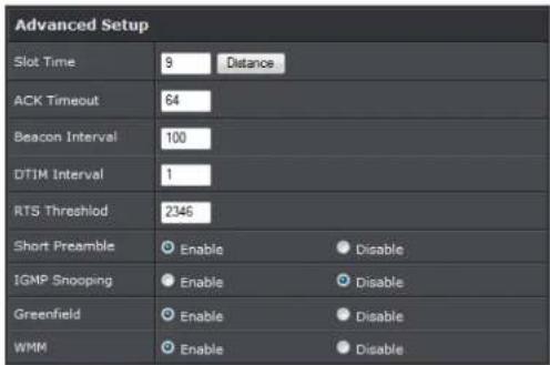
- Short Slot: By default, it's "Enable" for reducing the slot time from the standard 20 microseconds to the 9 microsecond short slot time. Slot time is the amount of time a device waits after a collision before retransmitting a packet. Reducing the slot time decreases the overall back-off, which increases throughput. Back-off, which is a multiple of the slot time, is the random length of time a station waits before sending a packet on the LAN. For a sender and receiver own right of the channel the shorter slot time help manage shorter wait time to re-transmit from collision because of hidden wireless clients or other causes. When collision sources can be removed sooner and other senders attempting to send are listening to the channel (CSMA/CA) the owner of the channel should continue ownership and finish their transmission and release the channel. Then, following ownership of the channel will be sooner for the new pair due to shorter slot time. However, when long duration of existing collision sources and shorter slot time exist the owners might experience subsequent collisions. When adjustment to longer slot time can't improve performance then RTS/CTS could supplement and help improve performance.
- ACK Timeout: ACK timeout is in the range of 1\~255 and set in unit of microsecond. The default value is 32 microsecond. All data transmission in 802.11b/g request an "Acknowledgement" (ACK) send by receiving radio. The transmitter will resend the original packet if correspondent ACK failed to arrive within specific time interval, also refer to as "ACK Timeout".
ACK Timeout is adjustable due to the fact that distance between two radio links may vary in different deployment. ACK Timeout makes significant influence in performance of long distance radio link. If ACK Timeout is set too short, transmitter
will start to "Resend" packet before ACK is received, and throughputs become low due to excessively high re-transmission. ACK Timeout is best determined by distance between the radios, data rate of average environment. The Timeout value is calculated based on round-trip time of packet with a little tolerance, so, if experiencing re-transmissions or poor performance the ACK Timeout could be made longer to accommodate.
- Beacon Interval: Beacon Interval is in the range of 20\~1024 and set in unit of millisecond. The default value is 100 msec.
Access Point (AP) in IEEE 802.11 will send out a special approximated 50-byte frame, called "Beacon". Beacon is broadcast to all the stations, provides the basic information of AP such as SSID, channel, encryption keys, signal strength, time stamp, support data rate.
All the radio stations received beacon recognizes the existence of such AP, and may proceed next actions if the information from AP matches the requirement. Beacon is sent on a periodic basis, the time interval can be adjusted.
By increasing the beacon interval, you can reduce the number of beacons and associated overhead, but that will likely delay the association and roaming process because stations scanning for available access points may miss the beacons. You can decrease the beacon interval, which increases the rate of beacons. This will make the association and roaming process very responsive; however, the network will incur additional overhead and throughput will go down.
- DTIM Interval: The DTIM interval is in the range of 1\~255. The default is 1.
DTIM is defined as Delivery Traffic Indication Message. It is used to notify the wireless stations, which support power saving mode, when to wake up to receive multicast frame. DTIM is necessary and critical in wireless environment as a mechanism to fulfill power-saving synchronization. A DTIM interval is a count of the number of beacon frames that must occur before the access point sends the buffered multicast frames. For instance, if DTIM Interval is set to 3, then the Wi-Fi clients will expect to receive a multicast frame after receiving three Beacon frame. The higher DTIM interval will help power saving and possibly decrease wireless throughput in multicast applications. - RTS Threshold: TRTS Threshold is in the range of 1\~2347 byte. The default is 2347 byte. The main purpose of enabling RTS by changing RTS threshold is to reduce possible collisions due to hidden wireless clients. RTS in AP will be enabled automatically if the packet size is larger than the Threshold value. By default, RTS is disabled in a normal environment supports non-jumbo frames.
- Short Preamble: By default, it's "Enable". To Disable is to use Long 128-bit Preamble
TRENDnet User's Guide
TEW-739APBO
Synchronization field. The preamble is used to signal "here is a train of data coming" to the receiver. The short preamble provides 72-bit Synchronization field to improve WLAN transmission efficiency with less overhead.
- WMM: By default, it's "Enabled".
Wireless WMM QoS Setup
To achieve optimal wireless performance, it is necessary to tweak advance setting per requirements properly, not necessary higher the better or lower. The administrator can change the RTS threshold and fragmentation threshold settings for the system. Please click on Wireless -> Advanced
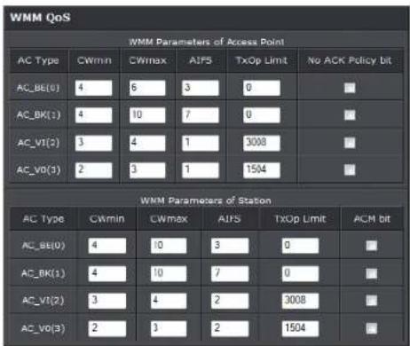
- WMM Parameters of Access Point: This affects traffic flowing from the access point to the client station
| Queue | Data Transmitted AP to Clients | Priority | Description |
| AC_BK | Background. | Low | High throughput. Bulk data that requires maximum throughput and is not time-sensitive is sent to this |
| queue (FTP data, for example). | |||
| AC_BE | Best Effort | Medium | Medium throughput and delay. Most traditional IP data is sent to this queue |
| AC_VI | Video High | Minimum delay. Time-sensitive video data is automatically sent to this queue | |
| AC_VO | Voice | High | Time-sensitive data like VoIP and streaming media are automatically sent to this queue |
Configuring QoS options consists of setting parameters on existing queues for different types of wireless traffic. You can configure different minimum and maximum wait times for the transmission of packets in each queue based on the requirements of the media being sent. Queues automatically provide minimum transmission delay for Voice, Video, multimedia, and mission critical applications, and rely on best-effort parameters for traditional IP data.
As an Example, time-sensitive Voice & Video, and multimedia are given effectively higher priority for transmission (lower wait times for channel access), while other applications and traditional IP data which are less time-sensitive but often more data-intensive are expected to tolerate longer wait times.
- Aifsn: The Arbitration Inter-Frame Spacing Number specifies a wait time (in milliseconds) for data frames
- CWmin: Minimum Contention Window. This parameter is input to the algorithm that determines the initial random back-off wait time ("window") for retry of a transmission. The value specified here in the Minimum Contention Window is the upper limit (in milliseconds) of a range from which the initial random back-off wait time is determined.
CWmax: Maximum Contention Window. The value specified here in the Maximum Contention Window is the upper limit (in milliseconds) for the doubling of the random back-off value. This doubling continues until either the data frame is sent or the Maximum Contention Window size is reached. Once the Maximum Contention Window size is reached, retries will continue until a maximum number of retries allowed is reached. Valid values for the "cwmax" are 1, 3, 7, 15, 31, 63, 127, 255, 511, or 1024. The value for "cwmax" must be higher than the value for "cwmin". - Txop: Transmission Opportunity is an interval of time when a WME AP has the right to initiate transmissions onto the wireless medium (WM). This value specifies (in milliseconds) the Transmission Opportunity (TXOP) for AP; that is, the
TRENDnet User's Guide
TEW-739APBO
interval of time when the WMM AP has the right to initiate transmissions on the wireless network.
- ACM: Admission Control Mandatory, ACM only takes effect on AC_VI and AC_VO. When you do not click Checkbox, it means that the ACM is controlled by the connecting AP. If you click Checkbox, it means that the Client is in charge.
- AckPolicy: Acknowledgment Policy, WMM defines two ACK policies: Normal ACK and No ACK. Click "Checkbox" indicates "No ACK"
| Queue | Data Transmitted Clients to AP | Priority Description | |
| AC_BK | Background. | Low | High throughput. Bulk data that requires maximum throughput and is not time-sensitive is sent to this queue (FTP data, for example). |
| AC_BE | Best Effort Medium | Medium throughput and delay. Most traditional IP data is sent to this queue | |
| AC_VI | Video | High | Minimum delay. Time-sensitive video data is automatically sent to this queue |
| AC_VO | Voice | High | Time-sensitive data like VoIP and streaming media are automatically sent to this queue |
When the no acknowledgment (No ACK) policy is used, the recipient does not acknowledge received packets during wireless packet exchange. This policy is suitable in the environment where communication quality is fine and interference is weak. While the No ACK policy helps improve transmission efficiency, it can cause increased packet loss when communication quality deteriorates. This is because when this policy is used, a sender does not retransmit packets that have not been received by the recipient. When the Normal ACK policy is used, the recipient acknowledges each received unicast packet.
- WMM Parameters of Station: This affects traffic flowing from the client station to the access point.
o Aifsn: The Arbitration Inter-Frame Spacing Number specifies a wait time (in
milliseconds) for data frames
- CWmin: Minimum Contention Window. This parameter is input to the algorithm that determines the initial random backoff wait time ("window") for retry of a transmission. The value specified here in the Minimum Contention Window is the upper limit (in milliseconds) of a range from which the initial random backoff wait time is determined.
- CWmax: Maximum Contention Window. The value specified here in the Maximum Contention Window is the upper limit (in milliseconds) for the doubling of the random backoff value. This doubling continues until either the data frame is sent or the Maximum Contention Window size is reached. Once the Maximum Contention Window size is reached, retries will continue until a maximum number of retries allowed is reached. Valid values for the "cwmax" are 1, 3, 7, 15, 31, 63, 127, 255, 511, or 1024. The value for "cwmax" must be higher than the value for "cwmin".
☐ Txop: Transmission Opportunity is an interval of time when a WME AP has the right to initiate transmissions onto the wireless medium (WM). This value specifies (in milliseconds) the Transmission Opportunity (Txop) for AP; that is, the interval of time when the WMM AP has the right to initiate transmissions on the wireless network. - ACM: Admission Control Mandatory, ACM only takes effect on AC_VI and AC_VO. When you do not click Checkbox, it means that the ACM is controlled by the connecting AP. If you click Checkbox, it means that the Client is in charge.
Click Save button to save your changes. Click Reboot button to activate your changes. The items in this page are for AP's RF advanced settings and will be applied to all VAPs and WDS Links.
TRENDnet User's Guide
TEW-739APBO
Create Virtual AP (VAP)
The TEW-739APBO support broadcasting multiple SSIDs, allowing the creation of Virtual Access Points, partitioning a single physical access point into 7 logical access points, each of which can have a different set of security, VLAN Tag(ID) and network settings. Figure 3-2 shows multiple SSIDs with different security type and VLAN settings.
![graph TD A["Sales Network"] -->|VLA N #1| B["Central Block"] C["Engineer Network"] -->|VLA N #2| B D["Market Network"] -->|VLA N #3| B E["Guest Network"] -->|VLA N #4| B F["Accounting Network"] -->|VLA N #5| B B --> G["SSID 1"] B --> H["SSID 2"] B --> I["SSID 3"] B --> J["SSID 4"] B --> K["SSID 5"]…](/content/2026/05/1078382/images/75dcaf2144064774211ead10a44f2f165cc7111c34b4cbdb98e979880dcd9b09.jpg)
Multiple SSIDs with different Security Type and VLAN Tag
Virtual AP Overview
The administrator can view all of the Virtual AP's settings via this page.
Please click on Wireless -> Virtual AP Setup and the Virtual AP Overview Page appears.
| VAP | MAC Address | ESSID | Status | Security Type | MAC Filter Edit | MAC Filter Status | VAP Edit |
| VAP0 | 00:22:AA:00:11:00 | TRENDnet7300_2.4GHz | Disabled | Edit | Disable | Edit | |
| VAP1 | TRENDnet7301_2.4GHz | Off | Disabled | Edit | Disable | Edit | |
| VAP2 | TRENDnet7302_2.4GHz | Off | Disabled | Edit | Disable | Edit | |
| VAP3 | TRENDnet7303_2.4GHz | Off | Disabled | Edit | Disable | Edit | |
| VAP4 | TRENDnet7304_2.4GHz | Off | Disabled | Edit | Disable | Edit | |
| VAP5 | TRENDnet7305_2.4GHz | Off | Disabled | Edit | Disable | Edit | |
| VAP6 | TRENDnet7306_2.4GHz | Off | Disabled | Edit | Disable | Edit | |
| VAP7 | TRENDnet7307_2.4GHz | Off | Disabled | Edit | Disable | Edit |
• VAP: Indicate the system's Virtual AP.
- MAC Address: The MAC address of the VAP Interface is displayed here. When you enable AP and reboot system, the MAC address will display here.
• ESSID: Indicate the ESSID of the respective Virtual AP
- Status: Indicate the Status of the respective Virtual AP. The Primary AP always on.
• Security Type: Indicate a used security type of the respective Virtual AP.
• MAC Filter: Indicate a used MAC filter of the respective Virtual AP.
- Edit: Click Edit button to configure Virtual AP's settings, including security type and MAC Filter.
TRENDnet User's Guide
TEW-739APBO
Virtual AP Setup
For each Virtual AP, administrators can configure SSID, VLAN tag (ID), SSID broadcasting, Maximum number of client associations, security type settings.
Click Edit button on the Edit column, and then a Virtual AP setup page appears.

- ESSID: Extended Service Set ID, when clients are browsing for available wireless networks, this is the SSID that will appear in the list. ESSID will determine the service type available to AP's clients associated with the specified VAP.
- Hidden SSID: By default, it's "Disable". Enable this option to stop the SSID broadcast in your network. When disabled, people could easily obtain the SSID information with the site survey software and get access to the network if security is not turned on. When enabled, network security is enhanced. It's suggested to enable it after AP security settings are archived and setting of AP clients could make to associate to it.
- Client Isolation: Select Enable, all clients will be isolated from each other, all clients cannot reach to other clients. Below Figures depict Client Isolation and AP Isolation
IAPP: - Maximum Clients: The default value is 32. You can enter the number of wireless clients that can associate to a particular SSID. When the number of client is set to 5, only 5 clients at most are allowed to connect to this VAP.
- VLAN Tag (ID): By default, it's selected "Disable".
This system supports tagged Virtual LAN (VLAN). A valid number of 1 to 4094 can be entered after it's enabled. If your network utilize VLANs you could tie a VLAN Tag to a specific SSID, and packets from/to wireless clients belonging to that SSID will be tagged with that VLAN Tag. This enables security of wireless applications by applying VLAN Tag.
- Security Type: Select the desired security type from the drop-down list; the options are Disable, WEP, WPA-PSK, WPA2-PSK, WPA-Enterprise, WPA2-Enterprise and
WEP 802.1X.
○ Disable: Data are unencrypted during transmission when this option is selected.
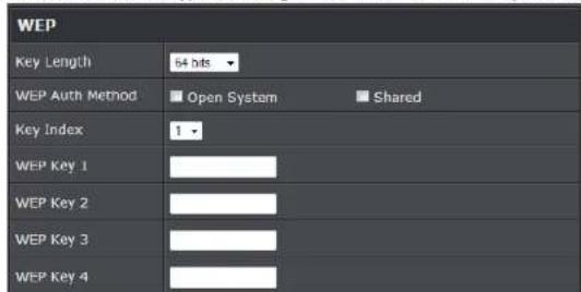
- WEP Auth Method: Enable the desire option among OPEN or SHARED
Key Index: Key index is used to designate the WEP key during data transmission. 4 different WEP keys can be entered at the same time, but only one is chosen.
- WEP Key #: Enter HEX or ASCII format WEP key value; the system supports up to 4 sets of WEP keys.
- WPA-PSK (or WPA2-PSK): WPA (or WPA2) Algorithms, allows the system accessing the network by using the WPA-PSK protected access.

- Cipher Suite: By default, it is AES. Select either AES or TKIP cipher suites
- Group Key Update Period: By default, it is 600 seconds. This time interval for rekeying GTK, broadcast/multicast encryption keys, in seconds. Entering the time-length is required.
Master Key Update Period: By default, it is 83499 seconds. This time interval for
TRENDnet User's Guide
TEW-739APBO
rekeying GTK, broadcast/multicast encryption keys, in seconds. Entering the time-length is required.
o Pre-shared Key: Enter the pre-shared key; the format shall go with the selected key type.
- WPA-Enterprise (or WPA2-Enterprise): The RADIUS authentication and encryption will be both enabled if this is selected.

• WPA General Settings:
- Cipher Suite: By default, it is AES. Select either AES or TKIP cipher suites
- Group Key Update Period: By default, it's 3600 seconds. This time interval for rekeying GTK, broadcast/multicast encryption keys, in seconds. Entering the time-length is required.
☐ Master Key Update Period: By default, it is 83499 seconds. This time interval for rekeying GTK, broadcast/multicast encryption keys, in seconds. Entering the time-length is required.
o EAP Reauth Period: By default, it's 3600 seconds. Set WPA2 PMKID cache timeout period, after time out, the cached key will be deleted.
o Pre-Authentication: By default, it's "Disable". To Enable is use to speed up roaming before pre-authenticating IEEE 802.1X/EAP part of the full RSN authentication and key handshake before actually associating with a new AP.
- Radius Server Settings :
- IP Address: Enter the IP address of the Authentication RADIUS server.
o Port: By default, it's 1812. The port number used to communicate with RADIUS server. - Shared secret: A secret key used between system and RADIUS server. Supports 8 to 64 characters.
- Accounting RADIUS Server: Enable to set Account RADIUS server.
- WEP 802.1X: When WEP 802.1x Authentication is enabled, please refer to the following Dynamic WEP and RADIUS settings to complete configuration.

- Radius Server Settings:
- IP Address: Enter the IP address of the Authentication RADIUS server.
- Port: By default, it's 1812. The port number used to communicate with RADIUS server.
- Shared secret: A secret key used between system and RADIUS server. Supports 8 to 64 characters.
- Accounting RADIUS Server: Enable to set Account RADIUS server.
Click Save button to save your changes. Click Reboot button to activate your changes
TRENDnet User's Guide
TEW-739APBO
Wireless MAC Filter Setup
Continue Virtual AP Setup section. For each Virtual AP setting, the administrator can allow or reject clients to access each Virtual AP.
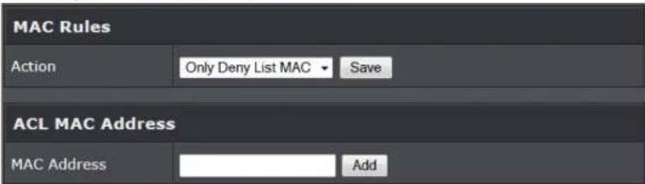
- MAC Filter Setup: By default, it's "Disable". Options are Disable, Only Deny List MAC or Only Allow List MAC.
Two ways to set MAC filter rules:
- Only Allow List MAC: The wireless clients in the "Enable" list will be allowed to access the Access Point; All others or clients in the "Disable" list will be denied.
- Only Deny List MAC: The wireless clients in the "Enable" list will be denied to access the Access Point; All others or clients in the "Disable" list will be allowed.
Add a station MAC: Enter MAC address (e.g. aa:bb:cc:00:00:0a) and click "Add" button, then the MAC address should display in the "Enable" List.
There are a maximum of 20 clients allowed in this "Enable" List. The MAC addresses of the wireless clients can be added and removed to the list using the Add and Remove buttons. Click Reboot button to activate your changes.
Wireless Network Expansion
The administrator could create WDS Links to expand wireless network. When WDS is enabled, access point functions as a wireless bridge and is able to communicate with other access points via WDS links. A WDS link is bidirectional and both sides must support WDS. Access points know each other by MAC Address. In other words, each access point needs to include MAC address of its peer. Ensure all access points are configured with the same channel and own same security type settings.
![graph LR A["Cloud"] --> B["Network"] B --> C["Remote Bass Station"] C --> D["WDS"] D --> E["SSID"] E --> F["Laptop"]](/content/2026/05/1078382/images/094e07d29a645fb5ea8646e821d4e3e4408b301b89a236c38cec454f06e0a442.jpg)
Please click on Wireless -> WDS Setup and follow the below setting.
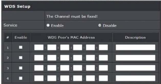
- Security Type: Option is "Disable", "WEP", "TKIP" or "AES" from drop-down list. Needs the same type to build WDS links. Security type takes effect when WDS is
TRENDnet User's Guide
TEW-739APBO
enabled.
o WEP Key: Enter 5 / 13 ASCII or 10 / 26 HEX format WEP key.
o TKIP Key: Enter 8 to 63 ASCII or 64 HEX format TKIP key.
o AES Key: Enter 8 to 63 ASCII or 64 HEX format AES key.
- WDS MAC List
- Enable: Click Enable to create WDS link.
o WDS Peer's MAC Address: Enter the MAC address of WDS peer.
○ Description: Description of WDS link.
Click Save button to save your changes. Click Reboot button to activate your changes
System Status
This section breaks down into subsections of System Overview, Associated Clients Status, WDS Link Status, Extra Information and Event Log.
System Overview
Display detailed information of System, Network, LAN and Wireless in the System Overview page.
• Device Information: Display the information of the system.
| Device Information | |
| Node | AP |
| Host Name | TEW-738AFBO |
| HOST Description | 10dB Outdoor PoE Access Point |
| Firmware Version | V1.0.19 |
| Firmware Date | 2014/04/23 09:44:S1 |
| Country | US |
| System Time | 2013/07/09 00:35:09 |
| System Up Time | 8 Day 00:35:27 |
| ETH1 MAC | 00:22:AA:00:11:07 |
| ETH2 MAC | 00:22:AA:00:11:06 |
| Wireless MAC | 00:22:AA:00:11:08 |
| CPU Loading | 0% |
| Memory Used | 71% |
- Operating Mode: The mode currently in service.
- Host Name: The name of the system.
○ Host Description: A description of the system.
o Firmware Version: The current installed firmware version.
o Firmware Date: The build time of installed firmware.
o Device Time: The current time of the system.
- System Up Time: The time period that system has been in service since last reboot.
o ETH1/ETH2MAC: Ethernet MAC address of the access point.
o Wireless MAC: Wireless MAC address of the access point
o CPU Loading: The CPU loading of the access point
o Memory Used: Memory usage of the access point.
• LAN Information: Display total received and transmitted statistics on the LAN interface.
| LAN Information | |
| Ethernet Connection Type | Static IP |
| IP Address | 192.168.10.100 |
| IP Netmask | 255.255.255.0 |
| IP Gateway | 192.168.10.1 |
| DNS | |
- Ethernet Connection Type: The connection applied on the access point.
- IP Address: The management IP of system. By default, it's 192.168.2.254.
- IP Netmask: The network mask. By default, it's 255.255.255.0.
- IP Gateway: The gateway IP addresses and by default, it's 192.168.2.1.
o Primary DNS: The primary DNS server in service.
TRENDnet User's Guide
TEW-739APBO
- Wireless Information: Display total received and transmitted statistics on available Virtual AP.
| Wireless Information | |
| WiFi | On |
| Band | 802.11b/g/n |
| Channel | 5 |
| Current Txpower | 28 dBm (630 mW) |
| Date Rate | Auto (300Mb/s) |
o WiFi: Wireless status of the access point.
- Band: Operating wireless band of the access point.
- Channel: Operating channel of the access point.
- Current Tx Power: Transmit power of the access point.
o Data Rate: Current wireless data rate of the access point.
Associated Clients Status
It displays ESSID, on/off Status, Security Type, and total number of wireless clients associated with all Virtual AP.
| VAP | ESSID | Status | Security Type | Clients |
| VAP0 | TRENDnet7380_2.4GHz | Disabled | 2 | |
| VAP1 | TRENDnet7381_2.4GHz | Off | Disabled | 0 |
| VAP2 | TRENDnet7382_2.4GHz | Off | Disabled | 0 |
| VAP3 | TRENDnet7383_2.4GHz | Off | Disabled | 0 |
| VAP4 | TRENDnet7384_2.4GHz | Off | Disabled | 0 |
| VAP5 | TRENDnet7385_2.4GHz | Off | Disabled | 0 |
| VAP6 | TRENDnet7386_2.4GHz | Off | Disabled | 0 |
| VAP7 | TRENDnet7387_2.4GHz | Off | Disabled | 0 |
• VAP Information: Highlights key VAP information.
- VAP: Available VAP from Primary AP to VAP6.
- ESSID: Display name of ESSID for each VAP.
Status : On/Off
o Security Type: Display chosen security type; WEP, WPA/WPA2-PSK, WPA/WPA2-
Enterprise.
- Clients: Display total number of wireless connections for each VAP.
• VAP Clients: Display all associated clients on each Virtual AP.
| # | MAC Address | RSSI | TX/RX Rate | TX/RX SEQ | TX/RX Bytes | Connect Time | Actions |
| 1 | 00:14:d1:c2:da:84 | 46 | 0 / 1 | 0 / 49872 | 0 / 1.0 M | 1 Day 19:40:10 | Disconnect |
| 2 | 3c:ab:8e:51:ad:b5 | 10 | 0 / 1 | 0 / 1136 | 0 / 150.9 K | 03:02:43 | Disconnect |
- MAC Address: MAC address of associated clients
- RSSI: Signal Strength of from associated clients.
o TX/RX Rate: Transmit and receive connection rate
o TX/RX SEQ: Transmit and receive sequence. - TX/RX Bytes: Transmit and receive bytes
- Connect Time: Connection time
- Disconnect: Click "Disconnect" button to manually disconnect a wireless client in a Virtual AP.
Show WDS Link Status
Peers MAC Address, antenna 0/1 received signal strength, phy mode and channel bandwidth for each WDS are available.
| # | MAC Address | RSSI | TX/RX Rate | TX/RX SEQ | TX/RX Bytes |
| No WDS Link! | |||||
○ MAC Address: Display MAC address of WDS peer.
o RSSI: Indicate the signal strength of the respective WDS links.
- TX/RX SEQ: Transmit and receive sequence.
- TX/RX Bytes: Transmit and receive bytes
TRENDnet User's Guide
TEW-739APBO
Extra Information
Users could pull out information such as Route table, ARP table, MAC table, Bridge table or STP available in the drop-down list from system. The "Refresh" button is used to retrieve latest table information.
| Extra Information | |||
| Information | Route Information | ||
| Route Information | |||
| Destination | Gateway | Netmask | Interface |
| 192.168.10.0 | 0.0.0.0 | 255.255.255.0 | bre0 |
| 239.0.0.0 | 0.0.0.0 | 255.0.0.0 | bre0 |
| 224.0.0.0 | 0.0.0.0 | 224.0.0.0 | bre0 |
| 0.0.0.0 | 192.168.10.1 | 0.0.0.0 | bre0 |
- Route table information: Select "Route table information" on the drop-down list to display route table. TEW-739APBO could be used as a L2 or L3 device. It doesn't support dynamic routing protocols such as RIP or OSPF. Static routes to specific hosts, networks or default gateway are set up automatically according to the IP configuration of system's interfaces. When used as a L2 device, it could switch packets and, as L3 device, it's capable of being a gateway to route packets inward and outward.
| Route Information | |||
| Destination | Gateway | Netmask | Interface |
| 192.168.10.0 | 0.0.0.0 | 255.255.255.0 | bre0 |
| 239.0.0.0 | 0.0.0.0 | 255.0.0.0 | bre0 |
| 224.0.0.0 | 0.0.0.0 | 224.0.0.0 | bre0 |
| 0.0.0.0 | 192.168.10.1 | 0.0.0.0 | bre0 |
- ARP table Information: Select "ARP Table Information" on the drop-down list to display ARP table. ARP associates each IP address to a unique hardware address (MAC) of a device. It is important to have a unique IP address as final destination to switch packets to.
| ARP Table Information | ||
| IP Address | MAC Address | Interface |
| 102.158.10.123 | 00:26:2d:5b:46:52 | bre0 |
- Bridge table information: Select "Bridge Table information" on the drop-down list to display bridge table. Bridge table will show Bridge ID and STP's Status on the each Ethernet bridge and its attached interfaces, the Bridge Port should be attached to some interfaces (e.g. eth2, ra0\~ra6 and wds0\~wds3).
| Bridge Table Information | |||
| Bridge Port | Bridge ID | STP Enabled | Interface |
| LAN | 8000.0022aa001106 | no | eth1 |
| eth0 | |||
| ath0 | |||
- Bridge MAC information: Select "Bridge MACs Information" on the drop-down list to display MAC table.
| Bridge MACs Table Information | |||
| Port | MAC Address | Local | Agcing Timer |
| VAP0 | 00:14:d1:c2:da:84 | no | 3.17 |
| LAN | 00:22:aa:00:11:06 | yes | 0.00 |
| WAN | 00:22:aa:00:11:07 | yes | 0.00 |
| VAP0 | 00:22:aa:00:11:08 | yes | 0.00 |
| WAN | 00:26:2d:5b:45:53 | no | 0.04 |
This table displays local MAC addresses associated with wired or wireless interfaces, but also remember non-local MAC addresses learned from wired or wireless interfaces. Ageing timers will be reset when existing MAC addresses in table are learned again or added when new MAC addresses are seen from wired or wireless interfaces as well. When time runs out for a particular entry, it will be pruned from the table. In that situation, switching packet to that particular MAC address will be dropped.
TRENDnet User's Guide
TEW-739APBO
Event Log
The Event log displays system events when system is up and running. Also, it becomes very useful as a troubleshooting tool when issues are experienced in system.
| Time | Facility | Severity | Message |
| 2013-07-0603:32:47 | System | Info | Authentication successful for admin from 192.168.10.123 |
• Time: The date and time when the event occurred.
- Facility: It helps users to identify source of events such "System" or "User"
- Severity: Severity level that a specific event is associated such as "info", "error", "warning", etc.
• Message: Description of the event.
Click Refresh button to renew the log, or click Clear button to clear all the record.
WDS Mode Configuration
Please refer to illustrations of the section 1.3 for possible applications in the WDS mode. This section provides detailed explanation for users to configure in the WDS mode with help of illustrations. In the WDS mode, functions listed in the table below are also available from the Web-based GUI interface.
WDS Mode Functions
| Option | System | Wireless | Utilities | Status |
| Functions | Operating | General Setup | Profiles Settings | System |
| LAN | Advanced Setup | Firmware | WDS Status | |
| Management | WDS Setup | Network Utility | Extra Info | |
| Time Server | Reboot | Event Log | ||
| SNMP |
External Network Connection
Network Requirement
You could expand your Ethernet network via WDS link. In this mode, the TEW-739APBO connects directly to a wired LAN, and wirelessly bridges to a remote access point via a WDS link as shown in Figure 4-1. In the mode, it can't associate with any wireless clients.
![graph LR A["Cloud"] --> B["Server"] B --> C["WDS"] C --> D["Device 1"] C --> E["Device 2"]](/content/2026/05/1078382/images/62a8f848fd2078946c66a7f82339f3a56a70fc874cc20ef32ca0cffe55e6a9de.jpg)
Point to Point network Configuration
TRENDnet User's Guide
TEW-739APBO
Configure LAN IP
Here are the instructions to setup the local IP Address and Netmask. Please click on System -> LAN and follow the below setting.
- Mode: Check either "Static IP" or "Dynamic IP" button as desired to set up the system IP of LAN port.

- Static IP: The administrator can manually setup the LAN IP address when static IP is available/ preferred.
- IP Address : The IP address of the LAN port; default IP address is 192.168.2.254
- IP Netmask: The Subnet mask of the LAN port; default Netmask is 255.255.255.0
- IP Gateway : The default gateway of the LAN port; default Gateway is 192.168.2.1
- Dynamic IP: This configuration type is applicable when the TEW-739APBO is connected to a network with the presence of a DHCP server; all related IP information will be provided by the DHCP server automatically.

○ Hostname : The Hostname of the LAN port
- DNS : Check either "No Default DNS Server" or "Specify DNS Server IP" button as desired to set up the system DNS.
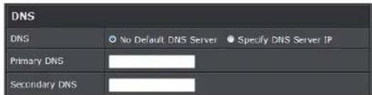
o Primary: The IP address of the primary DNS server.
- Secondary: The IP address of the secondary DNS server.
• 802.1d Spanning Tree

The spanning tree network protocol provides a loop free topology for a bridged LAN between LAN interface and 4 WDS interfaces from wds0 to wds3. The Spanning Tree Protocol, which is also referred to as STP, is defined in the IEEE Standard 802.1d. The Spanning tree feature is always enabled on TEW-739APBO. Below Figures depict a loop for a bridged LAN between LAN and WDS link
Click Save button to save your changes. Click Reboot button to activate your changes
Wireless Network Expansion
The network manager can configure related wireless settings, General Settings, Advanced Settings and WDS Settings.
Wireless General Setup
The administrator can change the data transmission, channel and output power settings for the system. Please click on Wireless -> General Setup and follow the below setting.
TRENDnet User's Guide
TEW-739APBO
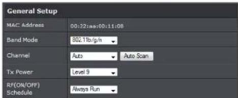
• MAC Address: The MAC address of the Wireless interface is displayed here.
- Band Mode: Select an appropriate wireless band; bands available are 801.11b, 802.11b/g, 802.11b/g/n or 802.11n only.
- Channel: Select the desired channel from the drop-down list to have the access point operate on. Click Auto Scan to scan for the best available channel to use based on the environment.
- Tx Power: You can adjust the output power of the system to get the appropriate coverage for your wireless network. Specify digit numbers between 1 to 100 (the unit is %) for your environment. If you are not sure which setting to choose, then keep the default setting, 100%.
- RF (ON/OFF) Schedule: Select an assigned schedule of when to have the access point turn on. Select Always Run to have the access point always on.
When Band Mode select in 802.11a only mode, the HT(High Throughput) settings should be hidden immediately.
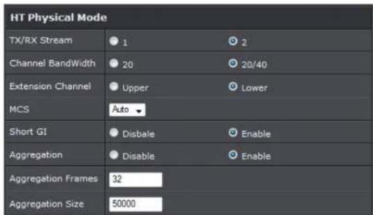
- TxStream/Rx Stream: Select the amount of transmit (TX) and Receive (RX) streams.
By default, it's 2.
- Channel Bandwidth: The "20/40" MHz option is usually best. The other option is available for special circumstances.
- Extensions Channel: Select which section of channels to use for extension channels.
- MCS: This parameter represents transmission rate. By default (Auto) the fastest possible transmission rate will be selected. You have the option of selecting the speed if necessary. (Refer to Appendix C. MCS Data Rate)
Wireless Advanced Setup
To achieve optimal wireless performance, it is necessary to tweak advance setting per requirements properly, not necessary higher the better or lower. The administrator can change the RTS threshold and fragmentation threshold settings for the system. Please click on Wireless -> Advanced Setup and follow the below setting.

- Short Slot: By default, it's "Enable" for reducing the slot time from the standard 20 microseconds to the 9 microsecond short slot time. Slot time is the amount of time a device waits after a collision before retransmitting a packet. Reducing the slot time decreases the overall back-off, which increases throughput. Back-off, which is a multiple of the slot time, is the random length of time a station waits before sending a packet on the LAN. For a sender and receiver own right of the channel the shorter slot time help manage shorter wait time to re-transmit from collision because of hidden wireless clients or other causes. When collision sources can be removed sooner and other senders attempting to send are listening the channel
TRENDnet User's Guide
TEW-739APBO
(CSMA/CA) the owner of the channel should continue ownership and finish their transmission and release the channel. Then, following ownership of the channel will be sooner for the new pair due to shorter slot time. However, when long duration of existing collision sources and shorter slot time exist the owners might experience subsequent collisions. When adjustment to longer slot time can't improve performance then RTS/CTS could supplement and help improve performance.
- ACK Timeout: ACK timeout is in the range of 1\~255 and set in unit of microsecond. The default value is 32 microsecond. All data transmission in 802.11b/g request an "Acknowledgement" (ACK) send by receiving radio. The transmitter will resend the original packet if correspondent ACK failed to arrive within specific time interval, also refer to as "ACK Timeout".
ACK Timeout is adjustable due to the fact that distance between two radio links may vary in different deployment. ACK Timeout makes significant influence in performance of long distance radio link. If ACK Timeout is set too short, transmitter will start to "Resend" packet before ACK is received, and throughputs become low due to excessively high re-transmission. ACK Timeout is best determined by distance between the radios, data rate of average environment. The Timeout value is calculated based on round-trip time of packet with a little tolerance, So, if experiencing re-transmissions or poor performance the ACK Timeout could be made longer to accommodate.
- Beacon Interval:: Beacon Interval is in the range of 20\~1024 and set in unit of millisecond. The default value is 100 msec.
Access Point (AP) in IEEE 802.11 will send out a special approximated 50-byte frame, called "Beacon". Beacon is broadcast to all the stations, provides the basic information of AP such as SSID, channel, encryption keys, signal strength, time stamp, support data rate.
All the radio stations received beacon recognizes the existence of such AP, and may proceed next actions if the information from AP matches the requirement. Beacon is sent on a periodic basis, the time interval can be adjusted.
By increasing the beacon interval, you can reduce the number of beacons and associated overhead, but that will likely delay the association and roaming process because stations scanning for available access points may miss the beacons. You can decrease the beacon interval, which increases the rate of beacons. This will make the association and roaming process very responsive; however, the network will incur additional overhead and throughput will go down.
- DTIM Interval: The DTIM interval is in the range of 1\~255. The default is 1. DTIM is defined as Delivery Traffic Indication Message. It is used to notify the
wireless stations, which support power saving mode, when to wake up to receive multicast frame. DTIM is necessary and critical in wireless environment as a mechanism to fulfill power-saving synchronization. A DTIM interval is a count of the number of beacon frames that must occur before the access point sends the buffered multicast frames. For instance, if DTIM Interval is set to 3, then the Wi-Fi clients will expect to receive a multicast frame after receiving three Beacon frame. The higher DTIM interval will help power saving and possibly decrease wireless throughput in multicast applications.
- RTS Threshold: TRTS Threshold is in the range of 1\~2347 byte. The default is 2347 byte. The main purpose of enabling RTS by changing RTS threshold is to reduce possible collisions due to hidden wireless clients. RTS in AP will be enabled automatically if the packet size is larger than the Threshold value. By default, RTS is disabled in a normal environment supports non-jumbo frames.
- Short Preamble: By default, it's "Enable". To Disable is to use Long 128-bit Preamble Synchronization field. The preamble is used to signal "here is a train of data coming" to the receiver. The short preamble provides 72-bit Synchronization field to improve WLAN transmission efficiency with less overhead.
- WMM: By default, it's "Enabled".
Wireless WMM QoS Setup
To achieve optimal wireless performance, it is necessary to tweak advance setting per requirements properly, not necessary higher the better or lower.
The administrator can change the RTS threshold and fragmentation threshold settings for the system. Please click on Wireless -> Advanced
TRENDnet User's Guide
TEW-739APBO
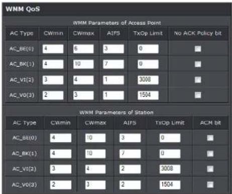
- WMM Parameters of Access Point: This affects traffic flowing from the access point to the client station
| Queue | Data Transmitted AP to Clients | Priority | Description |
| AC_BK | Background. | Low | High throughput. Bulk data that requires maximum throughput and is not time-sensitive is sent to this queue (FTP data, for example). |
| AC_BE | Best Effort | Medium | Medium throughput and delay. Most traditional IP data is sent to this queue |
| AC_VI Video High | Minimum delay. Time-sensitive video data is automatically sent to this queue | ||
| AC_VO | Voice | High | Time-sensitive data like VoIP and streaming media are automatically sent to this queue |
Configuring QoS options consists of setting parameters on existing queues for different types of wireless traffic. You can configure different minimum and maximum wait times for the transmission of packets in each queue based on the requirements of the media being sent. Queues automatically provide minimum transmission delay for Voice, Video, multimedia, and mission critical applications, and rely on best-effort
parameters for traditional IP data.
As an Example, time-sensitive Voice & Video, and multimedia are given effectively higher priority for transmission (lower wait times for channel access), while other applications and traditional IP data which are less time-sensitive but often more data-intensive are expected to tolerate longer wait times.
- Aifsn: The Arbitration Inter-Frame Spacing Number specifies a wait time (in milliseconds) for data frames
- CWmin: Minimum Contention Window. This parameter is input to the algorithm that determines the initial random back-off wait time ("window") for retry of a transmission. The value specified here in the Minimum Contention Window is the upper limit (in milliseconds) of a range from which the initial random back-off wait time is determined.
CWmax: Maximum Contention Window. The value specified here in the Maximum Contention Window is the upper limit (in milliseconds) for the doubling of the random back-off value. This doubling continues until either the data frame is sent or the Maximum Contention Window size is reached. Once the Maximum Contention Window size is reached, retries will continue until a maximum number of retries allowed is reached. Valid values for the "cwmax" are 1, 3, 7, 15, 31, 63, 127, 255, 511, or 1024. The value for "cwmax" must be higher than the value for "cwmin". - Txop: Transmission Opportunity is an interval of time when a WME AP has the right to initiate transmissions onto the wireless medium (WM). This value specifies (in milliseconds) the Transmission Opportunity (TXOP) for AP; that is, the interval of time when the WMM AP has the right to initiate transmissions on the wireless network.
- ACM: Admission Control Mandatory, ACM only takes effect on AC_VI and AC_VO. When you do not click Checkbox, it means that the ACM is controlled by the connecting AP. If you click Checkbox, it means that the Client is in charge.
- AckPolicy: Acknowledgment Policy, WMM defines two ACK policies: Normal ACK and No ACK. Click "Checkbox" indicates "No ACK"
TRENDnet User's Guide
TEW-739APBO
| Queue | Data Transmitted Clients to AP | Priority Description | |
| AC_BK | Background. | Low | High throughput. Bulk data that requires maximum throughput and is not time-sensitive is sent to this queue (FTP data, for example). |
| AC_BE | Best Effort Medium | Medium throughput and delay. Most traditional IP data is sent to this queue | |
| AC_VI | Video | High | Minimum delay. Time-sensitive video data is automatically sent to this queue |
| AC_VO | Voice | High | Time-sensitive data like VoIP and streaming media are automatically sent to this queue |
When the no acknowledgment (No ACK) policy is used, the recipient does not acknowledge received packets during wireless packet exchange. This policy is suitable in the environment where communication quality is fine and interference is weak. While the No ACK policy helps improve transmission efficiency, it can cause increased packet loss when communication quality deteriorates. This is because when this policy is used, a sender does not retransmit packets that have not been received by the recipient. When the Normal ACK policy is used, the recipient acknowledges each received unicast packet.
- WMM Parameters of Station: This affects traffic flowing from the client station to the access point.
- Aifsn : The Arbitration Inter-Frame Spacing Number specifies a wait time (in milliseconds) for data frames
○ CWmin : Minimum Contention Window. This parameter is input to the algorithm that determines the initial random backoff wait time ("window") for retry of a transmission. The value specified here in the Minimum Contention Window is the upper limit (in milliseconds) of a range from which the initial random backoff wait time is determined.
- CWmax : Maximum Contention Window. The value specified here in the
Maximum Contention Window is the upper limit (in milliseconds) for the doubling of the random backoff value. This doubling continues until either the data frame is sent or the Maximum Contention Window size is reached. Once the Maximum Contention Window size is reached, retries will continue until a maximum number of retries allowed is reached. Valid values for the "cwmax" are 1, 3, 7, 15, 31, 63, 127, 255, 511, or 1024. The value for "cwmax" must be higher than the value for "cwmin".
☐ Txop : Transmission Opportunity is an interval of time when a WME AP has the right to initiate transmissions onto the wireless medium (WM). This value specifies (in milliseconds) the Transmission Opportunity (Txop) for AP; that is, the interval of time when the WMM AP has the right to initiate transmissions on the wireless network.
- ACM: Admission Control Mandatory, ACM only takes effect on AC_VI and AC_VO. When you do not click Checkbox, it means that the ACM is controlled by the connecting AP. If you click Checkbox, it means that the Client is in charge.
Click Save button to save your changes. Click Reboot button to activate your changes. The items in this page are for AP's RF advanced settings and will be applied to all VAPs and WDS Links.
WDS Setup
The administrator could create WDS Links to expand wireless network. When WDS is enabled, access point functions as a wireless bridge and is able to communicate with other access points via WDS links. A WDS link is bidirectional and both side must support WDS. Access points know each other by MAC Address. In other words, each access point needs to include MAC address of its peer. Ensure all access points are configured with the same channel and own same security type settings.
TRENDnet User's Guide
TEW-739APBO
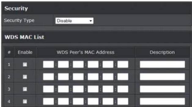
- Security Type: Option is "Disable", "WEP", "TKIP" or "AES" from drop-down list. Needs the same type to build WDS links. Security type takes effect when WDS is enabled.
o WEP Key: Enter 5 / 13 ASCII or 10 / 26 HEX format WEP key.
- TKIP Key: Enter 8 to 63 ASCII or 64 HEX format TKIP key.
o AES Key: Enter 8 to 63 ASCII or 64 HEX format AES key.
- WDS MAC List
- Enable: Click Enable to create WDS link.
- WDS Peer's MAC Address: Enter the MAC address of WDS peer.
- Description: Description of WDS link.
Click Save button to save your changes. Click Reboot button to activate your changes
System Status
This section breaks down into subsections of System Overview, Associated Clients Status, WDS Link Status, Extra Information and Event Log.
System Overview
Display detailed information of System, Network, LAN and Wireless in the System Overview page.
• Device Information: Display the information of the system.
| Device Information | |
| Mode | AI |
| Host Name | TEW-738APBO |
| Host Description | 10dBi Outdoor PoE Access Point |
| Firmware Version | V1.0.19 |
| Firmware Date | 2014/04/23 09:44:51 |
| Country | US |
| System Time | 2013/07/09 00:35:09 |
| System Up Time | 8 Day 00:35:27 |
| ETH1 MAC | 00:22:AA:00:11:07 |
| ETH2 MAC | 00:22:AA:00:11:06 |
| Wireless MAC | 00:22:AA:00:11:08 |
| CPU Loading | 0% |
| Memory Used | 71% |
○ Operating Mode: The mode currently in service.
- Host Name: The name of the system.
○ Host Description: A description of the system.
o Firmware Version: The current installed firmware version.
o Firmware Date: The build time of installed firmware.
o Device Time: The current time of the system.
o System Up Time: The time period that system has been in service since last reboot.
o ETH1/ETH2MAC: Ethernet MAC address of the access point.
o Wireless MAC: Wireless MAC address of the access point
o CPU Loading: The CPU loading of the access point
o Memory Used: Memory usage of the access point.
• LAN Information: Display total received and transmitted statistics on the LAN interface.
TRENDnet User's Guide
TEW-739APBO
| LAN Information | |
| Ethernet Connection Type | Static IP |
| IP Address | 192.168.10.100 |
| IP Netmask | 255.255.255.0 |
| IP Gateway | 192.168.10.1 |
| DNS | |
- Ethernet Connection Type: The connection applied on the access point.
- IP Address: The management IP of system. By default, it's 192.168.2.254.
- IP Netmask: The network mask. By default, it's 255.255.255.0.
-
IP Gateway: The gateway IP addresses and by default, it's 192.168.2.1.
o Primary DNS: The primary DNS server in service. -
Wireless Information: Display total received and transmitted statistics on available Virtual AP.
| Wireless Information | |
| WiFi | On |
| Band | 802.11b/g/n |
| Channel | 5 |
| Current Txpower | 28 dBm (630 mW) |
| Date Rate | Auto (300Mb/s) |
- WiFi: Wireless status of the access point.
- Band: Operating wireless band of the access point.
- Channel: Operating channel of the access point.
- Current Tx Power: Transmit power of the access point.
- Data Rate: Current wireless data rate of the access point.
Extra Information
Users could pull out information such as Route table, ARP table, MAC table, Bridge table
or STP available in the drop-down list from system. The "Refresh" button is used to retrieve latest table information.
| Extra Information | |||
| Information | Route information | ||
| Route Information | |||
| Destination | Gateway | Netmask | Interface |
| 192.108.10.0 | 0.0.0.0 | 255.255.255.0 | bre0 |
| 239.0.0.0 | 0.0.0.0 | 255.0.0.0 | bre0 |
| 224.0.0.0 | 0.0.0.0 | 224.0.0.0 | bre0 |
| 0.0.0.0 | 192.108.10.1 | 0.0.0.0 | bre0 |
- Route table information: Select "Route table information" on the drop-down list to display route table. TEW-739APBO could be used as a L2 or L3 device. It doesn't support dynamic routing protocols such as RIP or OSPF. Static routes to specific hosts, networks or default gateway are set up automatically according to the IP configuration of system's interfaces. When used as a L2 device, it could switch packets and, as L3 device, it's capable of being a gateway to route packets inward and outward.
| Route Information | |||
| Destination | Gateway | Netmask | Interface |
| 192.168.10.0 | 0.0.0.0 | 255.255.255.0 | bre0 |
| 239.0.0.0 | 0.0.0.0 | 255.0.0.0 | bre0 |
| 224.0.0.0 | 0.0.0.0 | 224.0.0.0 | bre0 |
| 0.0.0.0 | 192.168.10.1 | 0.0.0.0 | bre0 |
- ARP table Information: Select "ARP Table Information" on the drop-down list to display ARP table. ARP associates each IP address to a unique hardware address (MAC) of a device. It is important to have a unique IP address as final destination to switch packets to.
| ARP Table Information | ||
| IP Address | MAC Address | Interface |
| 102,168,10,123 | 00:26:2d:5b:46:53 | bro0 |
TRENDnet User's Guide
TEW-739APBO
- Bridge table information: Select "Bridge Table information" on the drop-down list to display bridge table. Bridge table will show Bridge ID and STP's Status on the each Ethernet bridge and its attached interfaces, the Bridge Port should be attached to some interfaces (e.g. eth2, ra0\~ra6 and wds0\~wds3).
| Bridge Table Information | |||
| Bridge Port | Bridge ID | STP Enabled | Interface |
| LAN | 8000.0022aa001106 | no | eth1 |
| eth0 | |||
| ath0 | |||
- Bridge MAC information: Select "Bridge MACs Information" on the drop-down list to display MAC table.
| Bridge MACs Table Information | |||
| Port | NAC Address | Local | Ageing Timer |
| VAP0 | 00:14:d1:e2:da:84 | nc | 3.17 |
| LAN | 00:22:aa:00:11:06 | yes | 0.00 |
| WAN | 00:22:38:00:11:07 | yes | 0.00 |
| VAP0 | 00:22:aa:00:11:08 | yes | 0.00 |
| WAN | 00:26:2d:5b:46:53 | nc | 0.04 |
This table displays local MAC addresses associated with wired or wireless interfaces, but also remember non-local MAC addresses learned from wired or wireless interfaces. Ageing timers will be reset when existing MAC addresses in table are learned again or added when new MAC addresses are seen from wired or wireless interfaces as well. When time runs out for a particular entry, it will be pruned from the table. In that situation, switching packet to that particular MAC address will be dropped.
Event Log
The Event log displays system events when system is up and running. Also, it becomes very useful as a troubleshooting tool when issues are experienced in system.
| Time | Facility | Severity | Message |
| 2013-07-0603:32:47 | System | Info | Authentication successful for admin from 192.168.10.123 |
• Time: The date and time when the event occurred.
- Facility: It helps users to identify source of events such "System" or "User"
- Severity: Severity level that a specific event is associated such as "info", "error", "warning", etc.
• Message: Description of the event.
Click Refresh button to renew the log, or click Clear button to clear all the record.
WDS Link Status
Peers MAC Address, antenna 0/1 received signal strength, phy mode and channel bandwidth for each WDS are available.
| # | MAC Address | RSSI | TX/RX Rate | TX/RX SEQ | TX/RX Bytes |
| No WDS Link! | |||||
○ MAC Address: Display MAC address of WDS peer.
o RSSI: Indicate the signal strength of the respective WDS links.
- TX/RX SEQ: Transmit and receive sequence.
- TX/RX Bytes: Transmit and receive bytes
TRENDnet User's Guide
TEW-739APBO
Repeater Mode
When Universal Repeater mode is activated, the system can be configured as an Access Point and Client Station simultaneously. This section provides information in configuring the Client Bridge+Universal Repeater mode with graphical illustrations. TEW-739APBO provides functions as stated below where they can be configured via a user-friendly web based interface.
External Network Connection
Network Requirement
It can be used as a Client Bridge or Universal Repeater to receive and repeat wireless signal over last mile applications, helping WISPs deliver wireless broadband Internet service to new residential and business customers. In this mode, TEW-739APBO is enabled with DHCP Server functions. The wired clients of TEW-739APBO are in the same subnet from Main Base Station and it accepts wireless connections from wireless client devices.
![graph LR A["Cloud"] --> B["Server"] B --> C["Main"] C --> D["Main Device"] D --> E["Laptop"] D --> F["Laptop"] D --> G["Laptop"] style A fill:#fff,stroke:#333 style B fill:#fff,stroke:#333 style C fill:#fff,stroke:#333 style D fill:#fff,stroke:#333 style E fill:#fff,stroke:#333 style F fill:#fff,str…](/content/2026/05/1078382/images/8559e7ba895d06174d28ba4cb958916785f3d11f297106046ba247093e5fb982.jpg)
Universal Repeater mode network Configuration
Configure LAN IP
Here are the instructions to setup the local IP Address and Netmask. Please click on System -> LAN and follow the below setting.
- Mode: Check either "Static IP" or "Dynamic IP" button as desired to set up the system IP of LAN port.

- Static IP: The administrator can manually setup the LAN IP address when static IP is available/ preferred.
- IP Address : The IP address of the LAN port; default IP address is 192.168.2.254
- IP Netmask: The Subnet mask of the LAN port; default Netmask is 255.255.255.0
- IP Gateway : The default gateway of the LAN port; default Gateway is 192.168.2.1
- Dynamic IP: This configuration type is applicable when the TEW-739APBO is connected to a network with the presence of a DHCP server; all related IP information will be provided by the DHCP server automatically.

○ Hostname : The Hostname of the LAN port
- DNS: Check either "No Default DNS Server" or "Specify DNS Server IP" button as desired to set up the system DNS.
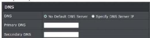
TRENDnet User's Guide
TEW-739APBO
o Primary: The IP address of the primary DNS server.
- Secondary: The IP address of the secondary DNS server.
• 802.1d Spanning Tree

The spanning tree network protocol provides a loop free topology for a bridged LAN between LAN interface and 4 WDS interfaces from wds0 to wds3. The Spanning Tree Protocol, which is also referred to as STP, is defined in the IEEE Standard 802.1d. Spanning tree always disabled on TEW-739APBO. Below Figures depict a loop for a bridged LAN between LAN and WDS link
- DHCP Setup: Devices connected to the system can obtain an IP address automatically when this service is enabled.

☐ DHCP: Check Enable button to activate this function or Disable to deactivate this service.
- Start IP / End IP: Specify the range of IP addresses to be used by the DHCP server when assigning IP address to clients. The default range IP address is 192.168.2.10 to 192.168.2.70, the netmask is 255.255.255.0
- DNS1 IP: Enter IP address of the first DNS server; this field is required.
- DNS2 IP: Enter IP address of the second DNS server; this is optional.
- WINS IP: Enter IP address of the Windows Internet Name Service (WINS) server; this is optional.
- Domain: Enter the domain name for this network.
Lease Time: The IP addresses given out by the DHCP server will only be valid for the duration specified by the lease time. Increasing the time ensure client operation without interruptions, but could introduce potential conflicts. Lowering the lease time will avoid potential address conflicts, but might cause more interruptions to the client while it will acquire new IP addresses from the DHCP server. Default is 86400 seconds
Click Save button to save your changes. Click Reboot button to activate your changes
Wireless Network Expansion
The network manager can configure related wireless settings, General Settings, Advanced Settings and WDS Settings.
Wireless General Setup
The administrator can change the data transmission, channel and output power settings for the system. Please click on Wireless -> General Setup and follow the below setting.
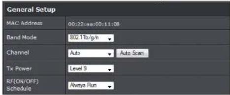
• MAC Address: The MAC address of the Wireless interface is displayed here.
- Band Mode: Select an appropriate wireless band; bands available are 801.11b, 802.11b/g, 802.11b/g/n or 802.11n only.
- Channel: Select the desired channel from the drop-down list to have the access point operate on. Click Auto Scan to scan for the best available channel to use based on the environment.
- Tx Power: You can adjust the output power of the system to get the appropriate coverage for your wireless network. Specify digit numbers between 1 to 100 (the unit is %) for your environment. If you are not sure which setting to choose, then keep the default setting, 100%.
- RF (ON/OFF) Schedule: Select an assigned schedule of when to have the access
TRENDnet User's Guide
TEW-739APBO
point turn on. Select Always Run to have the access point always on.
When Band Mode select in 802.11a only mode, the HT(High Throughput) settings should be hidden immediately.
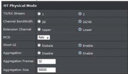
- TxStream/Rx Stream: Select the amount of transmit (TX) and Receive (RX) streams. By default, it's 2.
- Channel Bandwidth: The "20/40" MHz option is usually best. The other option is available for special circumstances.
- Extensions Channel: Select which section of channels to use for extension channels.
- MCS: This parameter represents transmission rate. By default (Auto) the fastest possible transmission rate will be selected. You have the option of selecting the speed if necessary. (Refer to Appendix C. MCS Data Rate)
Wireless Advanced Setup
To achieve optimal wireless performance, it is necessary to tweak advance setting per requirements properly, not necessary higher the better or lower.
The administrator can change the RTS threshold and fragmentation threshold settings for the system. Please click on Wireless -> Advanced Setup and follow the below setting.

- Short Slot: By default, it's "Enable" for reducing the slot time from the standard 20 microseconds to the 9 microsecond short slot time. Slot time is the amount of time a device waits after a collision before retransmitting a packet. Reducing the slot time decreases the overall back-off, which increases throughput. Back-off, which is a multiple of the slot time, is the random length of time a station waits before sending a packet on the LAN. For a sender and receiver own right of the channel the shorter slot time help manage shorter wait time to re-transmit from collision because of hidden wireless clients or other causes. When collision sources can be removed sooner and other senders attempting to send are listening the channel (CSMA/CA) the owner of the channel should continue ownership and finish their transmission and release the channel. Then, following ownership of the channel will be sooner for the new pair due to shorter slot time. However, when long duration of existing collision sources and shorter slot time exist the owners might experience subsequent collisions. When adjustment to longer slot time can't improve performance then RTS/CTS could supplement and help improve performance.
- ACK Timeout: ACK timeout is in the range of 1\~255 and set in unit of microsecond. The default value is 32 microsecond. All data transmission in 802.11b/g request an "Acknowledgement" (ACK) send by receiving radio. The transmitter will resend the original packet if correspondent ACK failed to arrive within specific time interval, also refer to as "ACK Timeout".
ACK Timeout is adjustable due to the fact that distance between two radio links may vary in different deployment. ACK Timeout makes significant influence in performance of long distance radio link. If ACK Timeout is set too short, transmitter
TRENDnet User's Guide
TEW-739APBO
will start to "Resend" packet before ACK is received, and throughputs become low due to excessively high re-transmission. ACK Timeout is best determined by distance between the radios, data rate of average environment. The Timeout value is calculated based on round-trip time of packet with a little tolerance, So, if experiencing re-transmissions or poor performance the ACK Timeout could be made longer to accommodate.
- Beacon Interval:: Beacon Interval is in the range of 20\~1024 and set in unit of millisecond. The default value is 100 msec.
Access Point (AP) in IEEE 802.11 will send out a special approximated 50-byte frame, called "Beacon". Beacon is broadcast to all the stations, provides the basic information of AP such as SSID, channel, encryption keys, signal strength, time stamp, support data rate.
All the radio stations received beacon recognizes the existence of such AP, and may proceed next actions if the information from AP matches the requirement. Beacon is sent on a periodic basis, the time interval can be adjusted.
By increasing the beacon interval, you can reduce the number of beacons and associated overhead, but that will likely delay the association and roaming process because stations scanning for available access points may miss the beacons. You can decrease the beacon interval, which increases the rate of beacons. This will make the association and roaming process very responsive; however, the network will incur additional overhead and throughput will go down.
- DTIM Interval: The DTIM interval is in the range of 1\~255. The default is 1. DTIM is defined as Delivery Traffic Indication Message. It is used to notify the wireless stations, which support power saving mode, when to wake up to receive multicast frame. DTIM is necessary and critical in wireless environment as a mechanism to fulfill power-saving synchronization. A DTIM interval is a count of the number of beacon frames that must occur before the access point sends the buffered multicast frames. For instance, if DTIM Interval is set to 3, then the Wi-Fi clients will expect to receive a multicast frame after receiving three Beacon frame. The higher DTIM interval will help power saving and possibly decrease wireless throughput in multicast applications.
- RTS Threshold: TRTS Threshold is in the range of 1\~2347 byte. The default is 2347 byte. The main purpose of enabling RTS by changing RTS threshold is to reduce possible collisions due to hidden wireless clients. RTS in AP will be enabled automatically if the packet size is larger than the Threshold value. By default, RTS is disabled in a normal environment supports non-jumbo frames.
- Short Preamble: By default, it's "Enable". To Disable is to use Long 128-bit Preamble
Synchronization field. The preamble is used to signal "here is a train of data coming" to the receiver. The short preamble provides 72-bit Synchronization field to improve WLAN transmission efficiency with less overhead.
• WMM: By default, it's "Enabled".
• Signal LED Threshold:

o LED1: Set the RSSI reading when LED1 will activate.
o LED2: Set the RSSI reading when LED2 will activate.
o LED3: Set the RSSI reading when LED3 will activate.
Change these settings as described here and click Save button to save your changes. Click Reboot button to activate your changes.
TRENDnet User's Guide
TEW-739APBO
Wireless WMM QoS Setup
To achieve optimal wireless performance, it is necessary to tweak advance setting per requirements properly, not necessary higher the better or lower.
The administrator can change the RTS threshold and fragmentation threshold settings for the system. Please click on Wireless -> Advanced

- WMM Parameters of Access Point: This affects traffic flowing from the access point to the client station
| Queue | Data Transmitted AP to Clients | Priority | Description |
| AC_BK | Background. | Low | High throughput. Bulk data that requires maximum throughput and is not time-sensitive is sent to this queue (FTP data, for example). |
| AC_BE | Best Effort | Medium | Medium throughput and delay. Most traditional IP data is sent to this queue |
| AC_VI | Video High | Minimum delay. Time-sensitive video data is automatically sent to this queue |
| AC_VO | Voice | High | Time-sensitive data like VoIP and streaming media are automatically sent to this queue |
Configuring QoS options consists of setting parameters on existing queues for different types of wireless traffic. You can configure different minimum and maximum wait times for the transmission of packets in each queue based on the requirements of the media being sent. Queues automatically provide minimum transmission delay for Voice, Video, multimedia, and mission critical applications, and rely on best-effort parameters for traditional IP data.
As an Example, time-sensitive Voice & Video, and multimedia are given effectively higher priority for transmission (lower wait times for channel access), while other applications and traditional IP data which are less time-sensitive but often more data-intensive are expected to tolerate longer wait times.
- Aifsn: The Arbitration Inter-Frame Spacing Number specifies a wait time (in milliseconds) for data frames
CWmin: Minimum Contention Window. This parameter is input to the algorithm that determines the initial random back-off wait time ("window") for retry of a transmission. The value specified here in the Minimum Contention Window is the upper limit (in milliseconds) of a range from which the initial random back-off wait time is determined.
CWmax: Maximum Contention Window. The value specified here in the Maximum Contention Window is the upper limit (in milliseconds) for the doubling of the random back-off value. This doubling continues until either the data frame is sent or the Maximum Contention Window size is reached. Once the Maximum Contention Window size is reached, retries will continue until a maximum number of retries allowed is reached. Valid values for the "cwmax" are 1, 3, 7, 15, 31, 63, 127, 255, 511, or 1024. The value for "cwmax" must be higher than the value for "cwmin". - Txop: Transmission Opportunity is an interval of time when a WME AP has the right to initiate transmissions onto the wireless medium (WM). This value specifies (in milliseconds) the Transmission Opportunity (TXOP) for AP; that is, the interval of time when the WMM AP has the right to initiate transmissions on the wireless network.
- ACM: Admission Control Mandatory, ACM only takes effect on AC_VI and AC_VO. When you do not click Checkbox, it means that the ACM is controlled by the connecting AP. If you click Checkbox, it means that the Client is in charge.
- AckPolicy: Acknowledgment Policy, WMM defines two ACK policies: Normal ACK and No ACK. Click "Checkbox" indicates "No ACK"
TRENDnet User's Guide
TEW-739APBO
| Queue | Data Transmitted Clients to AP | Priority Description | |
| AC_BK | Background. | Low | High throughput. Bulk data that requires maximum throughput and is not time-sensitive is sent to this queue (FTP data, for example). |
| AC_BE | Best Effort Medium | Medium throughput and delay. Most traditional IP data is sent to this queue | |
| AC_VI | Video | High | Minimum delay. Time-sensitive video data is automatically sent to this queue |
| AC_VO | Voice | High | Time-sensitive data like VoIP and streaming media are automatically sent to this queue |
When the no acknowledgment (No ACK) policy is used, the recipient does not acknowledge received packets during wireless packet exchange. This policy is suitable in the environment where communication quality is fine and interference is weak. While the No ACK policy helps improve transmission efficiency, it can cause increased packet loss when communication quality deteriorates. This is because when this policy is used, a sender does not retransmit packets that have not been received by the recipient. When the Normal ACK policy is used, the recipient acknowledges each received unicast packet.
- WMM Parameters of Station: This affects traffic flowing from the client station to the access point.
- Aifsn : The Arbitration Inter-Frame Spacing Number specifies a wait time (in milliseconds) for data frames
○ CWmin : Minimum Contention Window. This parameter is input to the algorithm that determines the initial random backoff wait time ("window") for retry of a transmission. The value specified here in the Minimum Contention Window is the upper limit (in milliseconds) of a range from which the initial random backoff wait time is determined. - CWmax : Maximum Contention Window. The value specified here in the
Maximum Contention Window is the upper limit (in milliseconds) for the doubling of the random backoff value. This doubling continues until either the data frame is sent or the Maximum Contention Window size is reached. Once the Maximum Contention Window size is reached, retries will continue until a maximum number of retries allowed is reached. Valid values for the "cwmax" are 1, 3, 7, 15, 31, 63, 127, 255, 511, or 1024. The value for "cwmax" must be higher than the value for "cwmin".
- Txop: Transmission Opportunity is an interval of time when a WME AP has the right to initiate transmissions onto the wireless medium (WM). This value specifies (in milliseconds) the Transmission Opportunity (Txop) for AP; that is, the interval of time when the WMM AP has the right to initiate transmissions on the wireless network.
- ACM: Admission Control Mandatory, ACM only takes effect on AC_VI and AC_VO. When you do not click Checkbox, it means that the ACM is controlled by the connecting AP. If you click Checkbox, it means that the Client is in charge.
Click Save button to save your changes. Click Reboot button to activate your changes. The items in this page are for AP's RF advanced settings and will be applied to all VAPs and WDS Links.
Site Survey
Use this tool to scan and locate WISP Access Points and select one to associate with. Please click on Wireless -> Site Survey. Below depicts an example for site survey.
| FSSID | MAC Address | Signal/Noise, dBm | RSSI | Signal Quality,% | Channel | Security | Select |
| WalkingSeed | 00:ED-4C:01:06:02 | -29 / -95 | 65 | 300% | 1 | WPA2-PSK/AES | Select |
| TRENDMA35RMA | 00:EB-97:AD-90:EC | -41 / -40 | 54 | 300% | 1 | WPA2-PSK/AES | Select |
| TrendinSiteN | 00:14:01:CS:70:44 | -69 / -95 | 26 | 76% | 1 | WPA2-PSK/AES | Select |
| TRENDriaS15_1_A99A_3273 | 00:11:02:04:08:40 | -30 / -45 | 65 | 300% | 1 | WPA2-PSK/AES | Select |
| ATT40 | 00:81:24:00:32:60 | -79 / -95 | 19 | 92% | 1 | WPA2-PSK/AES | Select |
| V72 | 00:EB-97:BC-10:00 | -62 / -45 | 33 | 92% | 1 | WPA2-PSK/AES | Select |
| TRENDria752_1_A99A_0019 | 00:AE-EC:CA-E3:CO | -32 / -95 | 63 | 300% | 7 | WPA2-PSK/AES | Select |
| TrendinSiteN | 00:14:01:CF:3F:0C | -48 / -95 | 47 | 60% | 11 | WPA2-PSK/AES | Select |
- ESSID: Available Extend Service Set ID of surrounding Access Points.
• MAC Address: MAC addresses of surrounding Access Points.
• Signal: Received signal strength of all found Access Points.
TRENDnet User's Guide
TEW-739APBO
- Channel: Channel numbers used by all found Access Points.
• Security: Security type by all found Access Points.
• Band: Wireless band used by all found Access Points.
• Network Type: Network type used by all found Access Points. - Select: Click "Select" to configure settings and associate with chosen AP.
Repeater AP Setup
The administrator can configure station profiles via this page.
Please click on Wireless -> Wireless Profile and follow the below setting.
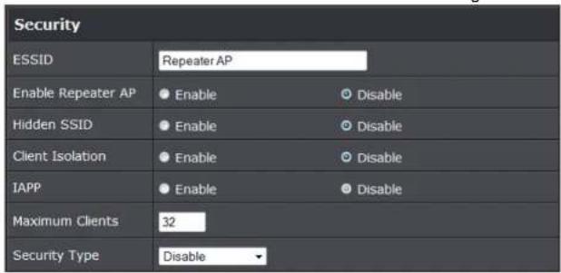
- ESSID: Assign Service Set ID for the wireless system.
- Enable Repeater SSID: Select Enable to broadcast the repeated signal.
- Hidden SSID: Select Enable to broadcast the access point's SSID.
- Client Isolation: Select Enable to isolate wireless clients from each other.
- IAPP:
- Maximum Clients: Enter the amount of wireless clients allowed to connect to the access point.
- Security Type: Select the desired security type from the drop-down list; the options are Disable, WEP, WPA-PSK, WPA2-PSK, WPA-Enterprise, WPA2-Enterprise and WEP 802.1X.
○ Disable: Data are unencrypted during transmission when this option is selected.

• WEP Auth Method: Enable the desire option among OPEN or SHARED
o Key Index: Key index is used to designate the WEP key during data transmission. 4 different WEP keys can be entered at the same time, but only one is chosen.
- WEP Key #: Enter HEX or ASCII format WEP key value; the system supports up to 4 sets of WEP keys.
- WPA-PSK (or WPA2-PSK): WPA (or WPA2) Algorithms, allows the system accessing the network by using the WPA-PSK protected access.

○ Cipher Suite: By default, it is AES. Select either AES or TKIP cipher suites
- Group Key Update Period: By default, it is 600 seconds. This time interval for rekeying GTK, broadcast/multicast encryption keys, in seconds. Entering the time-length is required.
Master Key Update Period: By default, it is 83499 seconds. This time interval for rekeying GTK, broadcast/multicast encryption keys, in seconds. Entering the time-length is required.
TRENDnet User's Guide
TEW-739APBO
o Pre-shared Key: Enter the pre-shared key; the format shall go with the selected key type.
- WPA-Enterprise (or WPA2-Enterprise): The RADIUS authentication and encryption will be both enabled if this is selected.

• WPA General Settings:
- Cipher Suite: By default, it is AES. Select either AES or TKIP cipher suites
- Group Key Update Period: By default, it's 3600 seconds. This time interval for rekeying GTK, broadcast/multicast encryption keys, in seconds. Entering the time-length is required.
Master Key Update Period: By default, it is 83499 seconds. This time interval for rekeying GTK, broadcast/multicast encryption keys, in seconds. Entering the time-length is required.
☐ EAP Reauth Period: By default, it's 3600 seconds. Set WPA2 PMKID cache timeout period, after time out, the cached key will be deleted.
o Pre-Authentication: By default, it's "Disable". To Enable is use to speed up roaming before pre-authenticating IEEE 802.1X/EAP part of the full RSN authentication and key handshake before actually associating with a new AP.
- Radius Server Settings:
-
IP Address: Enter the IP address of the Authentication RADIUS server.
o Port: By default, it's 1812. The port number used to communicate with RADIUS server. -
Shared secret: A secret key used between system and RADIUS server. Supports 8 to 64 characters.
- Accounting RADIUS Server: Enable to set Account RADIUS server.
- WEP 802.1X: When WEP 802.1x Authentication is enabled, please refer to the following Dynamic WEP and RADIUS settings to complete configuration.

- Radius Server Settings:
- IP Address: Enter the IP address of the Authentication RADIUS server.
o Port: By default, it's 1812. The port number used to communicate with RADIUS server. - Shared secret: A secret key used between system and RADIUS server. Supports 8 to 64 characters.
- Accounting RADIUS Server: Enable to set Account RADIUS server.
Key Index: key index is used to designate the WEP key during data transmission. 4 different WEP keys can be entered at the same time, but only one is chosen. - WEP Key #: Enter HEX or ASCII format WEP key value; the system supports up to 4 sets of WEP keys.
○ WPA-PSK (or WPA2-PSK): WPA (or WPA2) Algorithms, allows the system accessing the network by using the WPA-PSK protected access.
TRENDnet User's Guide
TEW-739APBO
Wireless MAC Filter Setup
The administrator can allow or reject clients to access Repeater AP.

- MAC Filter Setup: By default, it's "Disable". Options are Disable, Only Deny List
• MAC or Only Allow List MAC.
Two ways to set MAC filter rules:
- Only Allow List MAC: The wireless clients in the "Enable" list will be allowed to access the Access Point; All others or clients in the "Disable" list will be denied.
○ Only Deny List MAC: The wireless clients in the "Enable" list will be denied to access the Access Point; All others or clients in the "Disable" list will be allowed. - MAC: Enter MAC address (e.g. aa:bb:cc:00:00:0a) and click "Add" button, then the MAC address should display in the "Enable" List.
There are a maximum of 20 clients allowed in this "Enable" List. The MAC addresses of the wireless clients can be added and removed to the list using the Add and Remove buttons. Click Apply button to activate your changes
Create Wireless Profile
The administrator can configure station profiles via this page.
Please click on Wireless -> Wireless Profile and follow the below setting.
- Connection Setup: Select the repeater connection type.

- Fix: Select to have access point fixed on one profile to repeat
○ Cycle: Select to have access point cycle through different profiles.
- General Configuration:

• MAC Address: The MAC address of the Wireless Station is displayed here.
• Profile Name: Set different profiles for quick connection uses.
• ESSID: Assign Service Set ID for the wireless system.
- Lock to AP MAC: This allows the station to always maintain connection to a particular AP with a specific MAC address. This is useful as sometimes there can be few identically named SSID's (AP's) with different MAC addresses. With AP lock on, the station will lock to MAC address and not roam between several Access Points with the same ESSID.
- Security Type: Select the desired security type from the drop-down list; the options are Disable, WEP, WPA-PSK, WPA2-PSK, WPA-Enterprise, WPA2-Enterprise and WEP 802.1X.
○ Disable: Data are unencrypted during transmission when this option is selected.
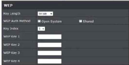
- WEP Auth Method: Enable the desire option among OPEN or SHARED
o Key Index: Key index is used to designate the WEP key during data transmission. 4 different WEP keys can be entered at the same time, but only one is chosen.
TRENDnet User's Guide
TEW-739APBO
- WEP Key #: Enter HEX or ASCII format WEP key value; the system supports up to 4 sets of WEP keys.
- WPA-PSK (or WPA2-PSK): WPA (or WPA2) Algorithms, allows the system accessing the network by using the WPA-PSK protected access.

- Cipher Suite: By default, it is AES. Select either AES or TKIP cipher suites
☐ Group Key Update Period: By default, it is 600 seconds. This time interval for rekeying GTK, broadcast/multicast encryption keys, in seconds. Entering the time-length is required.
Master Key Update Period: By default, it is 83499 seconds. This time interval for rekeying GTK, broadcast/multicast encryption keys, in seconds. Entering the time-length is required.
o Pre-shared Key: Enter the pre-shared key; the format shall go with the selected key type.
- WPA-Enterprise (or WPA2-Enterprise): The RADIUS authentication and encryption will be both enabled if this is selected.
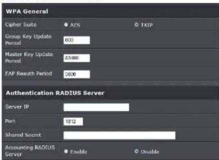
• WPA General Settings:
- Cipher Suite: By default, it is AES. Select either AES or TKIP cipher suites
- Group Key Update Period: By default, it's 3600 seconds. This time interval for rekeying GTK, broadcast/multicast encryption keys, in seconds. Entering the time-length is required.
Master Key Update Period: By default, it is 83499 seconds. This time interval for rekeying GTK, broadcast/multicast encryption keys, in seconds. Entering the time-length is required. - EAP Reauth Period: By default, it's 3600 seconds. Set WPA2 PMKID cache timeout period, after time out, the cached key will be deleted.
o Pre-Authentication: By default, it's "Disable". To Enable is use to speed up roaming before pre-authenticating IEEE 802.1X/EAP part of the full RSN authentication and key handshake before actually associating with a new AP.
- Radius Server Settings :
- IP Address: Enter the IP address of the Authentication RADIUS server.
o Port: By default, it's 1812. The port number used to communicate with RADIUS server. - Shared secret: A secret key used between system and RADIUS server. Supports 8 to 64 characters.
- Accounting RADIUS Server: Enable to set Account RADIUS server.
- WEP 802.1X: When WEP 802.1x Authentication is enabled, please refer to the following Dynamic WEP and RADIUS settings to complete configuration.
TRENDnet User's Guide
TEW-739APBO

- Radius Server Settings:
o IP Address: Enter the IP address of the Authentication RADIUS server.
- Port: By default, it's 1812. The port number used to communicate with RADIUS server.
- Shared secret: A secret key used between system and RADIUS server. Supports 8 to 64 characters.
- Accounting RADIUS Server: Enable to set Account RADIUS server.
Key Index: key index is used to designate the WEP key during data transmission. 4 different WEP keys can be entered at the same time, but only one is chosen.
- WEP Key #: Enter HEX or ASCII format WEP key value; the system supports up to 4 sets of WEP keys.
o WPA-PSK (or WPA2-PSK): WPA (or WPA2) Algorithms, allows the system accessing the network by using the WPA-PSK protected access.
Bandwidth Control
Bandwidth control allows you to control the bandwidth going through the access point.
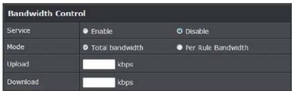
• Service: Select Enable to turn on bandwidth control through the access point.
- Mode: Select the bandwidth control mode to use through the access point.
- Upload: Enter the upload bandwidth speeds
- Download: Enter the download bandwidth speeds
Configure SNMP Setup
SNMP is an application-layer protocol that provides a message format for communication between SNMP managers and agents. By enabling SNMP function, the administrator can obtain the system information remotely.
Please click on System -> SNMP Setup and follow the below setting.

TRENDnet User's Guide
TEW-739APBO
• SNMP v2c Enable: Check to enable SNMP v2c.
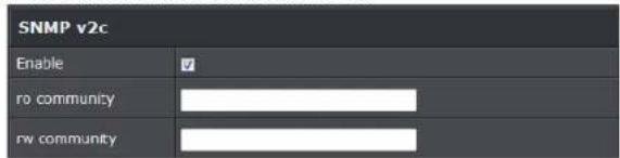
o ro community: Set a community string to authorize read-only access.
- rw community: Set a community string to authorize read/write access.
• SNMP v3 Enable: Check to enable SNMP v3.
SNMPv3 supports the highest level SNMP security.

o SNMP ro user: Set a community string to authorize read-only access.
o SNMP ro password: Set a password to authorize read-only access.
o SNMP rw user: Set a community string to authorize read/write access.
- SNMP rw password: Set a password to authorize read/write access.
- SNMP Trap: Events such as cold start, interface up & down, and association & disassociation will report to an assigned server.
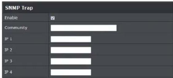
o Community: Set a community string required by the remote host computer that will receive trap messages or notices send by the system.
- IP: Enter the IP addresses of the remote hosts to receive trap messages.
Click Save button to save changes and click Reboot button to activate.
Configure Time Policy
Configure time policy to apply on settings like access point Radio Schedule.

- Policy: Select the policy to configure. Click Save Action to save settings.
-
Schedule Rule:
-
On Schedule: Select to have policy run on exact schedule
- Out of Schedule: Select to have policy run outside of schedule.
• Time Schedule:
- Day of week: Select the days of the week to apply time policy
- Start From: Enter time policy start time
TRENDnet User's Guide
TEW-739APBO
- End at: Enter the end time of time policy
System Status
This section breaks down into subsections of System Overview, Associated Clients Status, WDS Link Status, Extra Information and Event Log.
System Overview
Display detailed information of System, Network, LAN and Wireless in the System Overview page.
• Device Information: Display the information of the system.
| Device Information | |
| Node | Repeater |
| Host Name | TEW-730APDO |
| Host Description | 10dBI Outdoor PoE Access Point |
| Firmware Version | V1.0.19 |
| Firmware Date | 2014/04/23 09:44:51 |
| Country | US |
| System Time | 2014/05/05 14:49:12 |
| System Up Time | 03:58:31 |
| ETH1 MAC | 00:22:AA:00:11:07 |
| ETH2 MAC | 00:22:AA:00:11:06 |
| Wireless MAC | 00:22:AA:00:11:08 |
○ Operating Mode: The mode currently in service.
- Host Name: The name of the system.
- Host Description: A description of the system.
o Firmware Version: The current installed firmware version.
o Firmware Date: The build time of installed firmware.
- Device Time: The current time of the system.
o System Up Time: The time period that system has been in service since last reboot.
o ETH1/ETH2MAC: Ethernet MAC address of the access point.
o Wireless MAC: Wireless MAC address of the access point
o CPU Loading: The CPU loading of the access point
o Memory Used: Memory usage of the access point.
• LAN Information: Display total received and transmitted statistics on the LAN interface.
| LAN Information | |
| Ethernet Connection Type | Static IP |
| IP Address | 192.168.10.100 |
| IP Netmask | 255.255.255.0 |
| IP Gateway | 192.168.10.1 |
| DNS | |
- Ethernet Connection Type: The connection applied on the access point.
- IP Address: The management IP of system. By default, it's 192.168.2.254.
- IP Netmask: The network mask. By default, it's 255.255.255.0.
- IP Gateway: The gateway IP addresses and by default, it's 192.168.2.1.
o Primary DNS: The primary DNS server in service.
- Wireless Information: Display total received and transmitted statistics on available Virtual AP.
| Wireless Information | |
| WiFi | On |
| Band | 802.11b/g/n |
| Channel | 5 |
| Current Txpower | 28 dBm (630 mW) |
| Date Rate | Auto (300Mb/s) |
o WiFi: Wireless status of the access point.
- Band: Operating wireless band of the access point.
- Channel: Operating channel of the access point.
o Current Tx Power: Transmit power of the access point.
TRENDnet User's Guide
TEW-739APBO
- Data Rate: Current wireless data rate of the access point.
DHCP Client
Display detailed information of the access point's DHCP server.
| DHCP Server Status | |
| Service | Enable |
| Start IP | 192.166.10.101 |
| End IP | 192.166.10.254 |
| Default Gateway | 192.366.10.100 |
| DNS1 | 192.166.10.100 |
| DNS2 | |
| WINS | |
| Domain | |
| Lease Time | 86400 |
• Service: Status of access point's DHCP server
- Start IP: Starting IP address of access point's DHCP server
- End IP: Last IP address used on the access point's DHCP server
- Default Gateway: Assigned gateway address to the access point
- DNS1/2: Assigned DNS to the access point's DHCP server
- WINS: Assigned WINS to the access point's DHCP server
• Domain: Domain assigned to access point
- Lease Time: DHCP lease time of access point's DHCP server
| DHCP Client List | ||
| IP Address | MAC Address | Expired In |
| - | - | - |
- DHCP Client list: List of clients connected to the access point
Extra Information
Users could pull out information such as Route table, ARP table, MAC table, Bridge table or STP available in the drop-down list from system. The "Refresh" button is used to retrieve latest table information.
| Extra Information | |||
| Information | Route information | ||
| Route Information | |||
| Destination | Gateway | Netmask | Interface |
| 192.168.10.0 | 0.0.0.0 | 255.755.755.0 | bre0 |
| 239.0.0.0 | 0.0.0.0 | 255.0.0.0 | bre0 |
| 224.0.0.0 | 0.0.0.0 | 224.0.0.0 | bre0 |
| 0.0.0.0 | 192.168.10.1 | 0.0.0.0 | bre0 |
- Route table information: Select "Route table information" on the drop-down list to display route table. TEW-739APBO could be used as a L2 or L3 device. It doesn't support dynamic routing protocols such as RIP or OSPF. Static routes to specific hosts, networks or default gateway are set up automatically according to the IP configuration of system's interfaces. When used as a L2 device, it could switch packets and, as L3 device, it's capable of being a gateway to route packets inward and outward.
| Route Information | |||
| Destination | Gateway | Netmask | Interface |
| 192.168.10.0 | 0.0.0.0 | 255.255.255.0 | bre0 |
| 239.0.0.0 | 0.0.0.0 | 255.0.0.0 | bre0 |
| 224.0.0.0 | 0.0.0.0 | 224.0.0.0 | bre0 |
| 0.0.0.0 | 192.168.10.1 | 0.0.0.0 | bre0 |
- ARP table Information: Select "ARP Table Information" on the drop-down list to display ARP table. ARP associates each IP address to a unique hardware address (MAC) of a device. It is important to have a unique IP address as final destination to switch packets to.
TRENDnet User's Guide
TEW-739APBO
| ARP Table Information | ||
| IP Address | MAC Address | Interface |
| 192.168.10.123 | 00:26:2d:5b:46:52 | bre0 |
- Bridge table information: Select "Bridge Table information" on the drop-down list to display bridge table. Bridge table will show Bridge ID and STP's Status on the each Ethernet bridge and its attached interfaces, the Bridge Port should be attached to some interfaces (e.g. eth2, ra0\~ra6 and wds0\~wds3).
| Bridge Table Information | |||
| Bridge Port | Bridge ID | STP Enabled | Interface |
| LAN | 8000.0022aa001106 | no | eth1 |
| eth0 | |||
| ath0 | |||
- Bridge MAC information: Select "Bridge MACs Information" on the drop-down list to display MAC table.
| Bridge MACs Table Information | |||
| Port | NAC Address | Local | Agcing Timer |
| VAP0 | 00:14:d1:c2:da:B4 | no | 3.17 |
| LAN | 00:22:aa:00:11:06 | yes | 0.00 |
| WAN | 00:22:aa:00:11:07 | yes | 0.00 |
| VAP0 | 00:22:aa:00:11:08 | yes | 0.00 |
| WAN | 00:26:2d:Sb:45:53 | no | 0.04 |
This table displays local MAC addresses associated with wired or wireless interfaces, but also remember non-local MAC addresses learned from wired or wireless interfaces. Ageing timers will be reset when existing MAC addresses in table are learned again or added when new MAC addresses are seen from wired or wireless interfaces as well. When time runs out for a particular entry, it will be pruned from the table. In that situation, switching packet to that particular MAC address will be dropped.
Event Log
The Event log displays system events when system is up and running. Also, it becomes very useful as a troubleshooting tool when issues are experienced in system.
| Time | Facility | Severity | Message |
| 2013-07-0603:32:47 | System | Info | Authentication successful for admin from 192.168.10.123 |
• Time: The date and time when the event occurred.
- Facility: It helps users to identify source of events such "System" or "User"
- Severity: Severity level that a specific event is associated such as "info", "error", "warning", etc.
- Message: Description of the event.
Click Refresh button to renew the log, or click Clear button to clear all the record.
Associated Client List
List of all clients associated to the access point.
| # | MAC Address | RSSI | TX/RX Rate | TX/RX SEQ | TX/RX Bytes | Connect Time | Actions |
| No such device | |||||||
o MAC Address: Display MAC address of WDS peer.
o RSSI: Indicate the signal strength of the respective WDS links.
- TX/RX SEQ: Transmit and receive sequence.
- TX/RX Bytes: Transmit and receive bytes
TRENDnet User's Guide
TEW-739APBO
Remote AP status
List the current status of the remote access point.
| ESSID | MAC Address | Signal/Noise | RSSI | Signal Quality, % | TX/RX Rate | Status |
| TRENDnet7380_2.4GHz | 0 / 0 | 0 | 0% | 0M / 0M | 100MHz |
o ESSID: SSID of remote access point
o MAC Address: Display MAC address of WDS peer.
o RSSI: Indicate the signal strength of the respective WDS links.
o TX/RX SEQ: Transmit and receive sequence.
- TX/RX Bytes: Transmit and receive bytes
o Status: Display current association status of remote access point
CPE + AP Mode Configuration
When CPE+AP mode is chosen, the system can be configured as a Customer Premises Equipment (CPE). This section provides detailed explanation for users to configure in the CPE+AP mode with help of illustrations. In the CPE+AP mode, functions listed in the table below are also available from the Web-based GUI interface.
External Network Connection
Network Requirement
It can be used as an Outdoor Customer Premises Equipment (CPE) to receive and repeat wireless signal over last mile application, helping WISPs deliver wireless broadband Internet service to residents and business customers. In the CPE+AP mode, TEW-739APBO is a gateway enabled with NAT and DHCP Server functions. The wired and wireless clients connected to TEW-739APBO are in different subnet from those connected to Main Base Station, and, in CPE+AP mode, it accepts wireless connections from wireless client devices.
![graph LR A["Cloud"] --> B["Main"] B --> C["Switch"] C --> D["Laptop"] C --> E["Laptop"] C --> F["Laptop"] style A fill:#fff,stroke:#000 style B fill:#fff,stroke:#000 style C fill:#fff,stroke:#000 style D fill:#fff,stroke:#000 style E fill:#fff,stroke:#000 style F fill:#fff,stroke:#000](/content/2026/05/1078382/images/32621d492f46a500221d79f902e2ee23f48bd94db7ab70b2a9a576f13193f2db.jpg)
TRENDnet User's Guide
TEW-739APBO
Configure CPE Setup
There are three connection types for the WAN port: Static IP, Dynamic IP, PPPoE and PPTP.
Please click on System -> WAN and follow the below setting.
- Mode: Check "Static IP", "Dynamic IP", "PPPoE" or "PPTP" to set up system WAN IP.

- Static IP: Users can manually setup the WAN IP address with a static IP provided by WISP.
o IP Address: The IP address of the WAN port; default IP address is 192.168.1.254
- IP Netmask: The Subnet mask of the WAN port; default Netmask is 255.255.255.0
- IP Gateway: The default gateway of the WAN port; default Gateway is 192.168.1.1
- Dynamic IP: Please consult with WISP for correct wireless settings to associate with WISP AP before a dynamic IP, along with related IP settings including DNS can be available from DHCP server. If IP Address is not assigned, please double check with your wireless settings and ensure successful association. Also, you may go to "WAN Information" in the Overview page to click Release button to release IP address and click Renew button to renew IP address again.
Dynamic IP
Hostname

○ Hostname : The Hostname of the WAN port
- PPPoE : To create wireless PPPoE WAN connection to a PPPoE server in network.
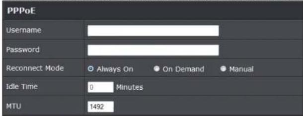
- User Name : Enter User Name for PPPoE connection
- Password : Enter Password for PPPoE connection
-
Reconnect Mode:
-
Always on: A connection to Internet is always maintained.
- On Demand: A connection to Internet is made as needed.
- Manual: Click the "Connect" button on "WAN Information" in the Overview page to connect to the Internet.
- Idle Time: Time to last before disconnecting PPPoE session when it is idle. Enter preferred Idle Time in minutes. Default is "0", indicates disabled. When Idle time is disabled, the "Reconnect Mode" will turn out "Always on"
- MTU: By default, it's 1492 bytes. MTU stands for Maximum Transmission Unit. Consult with WISP for a correct MTU setting.
TRENDnet User's Guide
TEW-739APBO
- PPTP: The Point-to-Point Tunneling Protocol (PPTP) mode enables the implementation of secure multi-protocol Virtual Private Networks (VPNs) through public networks.

• IP Address: The IP address of the WAN port
• IP Netmask: The Subnet mask of the WAN port
- PPTP Server IP Address: The IP address of the PPTP server
- User Name : Enter User Name for PPTP connection
- Password: Enter Password for PPTP connection
- Reconnect Mode:
- Always on: A connection to Internet is always maintained.
- On Demand: A connection to Internet is made as needed.
o Manual: Click the "Connect" button on "WAN Information" in the Overview page to connect to the Internet.
- Idle Time: Time to last before disconnecting PPPoE session when it is idle. Enter preferred Idle Time in minutes. Default is "0", indicates disabled. When Idle time is disabled, the "Reconnect Mode" will turn out "Always on"
- MTU: By default, it's 1460 bytes. MTU stands for Maximum Transmission Unit. Consult with WISP for a correct MTU setting.
- MPPE Encryption: Microsoft Point-to-Point Encryption (MPPE) encrypts data in Point-to-Point Protocol (PPP)-based dial-up connections or Point-to-Point Tunneling Protocol (PPTP) virtual private network (VPN) connections. 128-bit key (strong) and 40-bit key (standard) MPPE encryption schemes are supported. MPPE provides data
security for the PPTP connection that is between the VPN client and the VPN server.
- DNS: Check "No Default DNS Server" or "Specify DNS Server IP" radial button as desired to set up system DNS.

• Primary: The IP address of the primary DNS server.
• Secondary: The IP address of the secondary DNS server.
Click Save button to save your changes. Click Reboot button to activate your changes
Configure DDNS Setup
Dynamic DNS allows you to map domain name to dynamic IP address.
Please click on System -> DDNS Setup and follow the below setting.
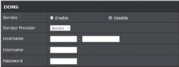
- Enabled: By default, it's "Disable". The mapping domain name won't change when dynamic IP changes. The beauty of it is no need to remember the dynamic WAP IP while accessing to it.
- Service Provider: Select the preferred Service Provider from the drop-down list including dyndns, dhs, ods and tzo
- Hostname: Host Name that you register to Dynamic-DNS service and export.
- User Name & Password: User Name and Password are used to login DDNS service. Click Save button to save your changes. Click Reboot button to activate your changes
TRENDnet User's Guide
TEW-739APBO
Configure LAN IP
Here are the instructions to setup the local IP Address and Netmask. Please click on System -> LAN and follow the below setting.
- Mode: Check either "Static IP" or "Dynamic IP" button as desired to set up the system IP of LAN port.

- Static IP: The administrator can manually setup the LAN IP address when static IP is available/ preferred.
- IP Address: The IP address of the LAN port; default IP address is 192.168.2.254
- IP Netmask: The Subnet mask of the LAN port; default Netmask is 255.255.255.0
- IP Gateway : The default gateway of the LAN port; default Gateway is 192.168.2.1
- Dynamic IP: This configuration type is applicable when the TEW-739APBO is connected to a network with the presence of a DHCP server; all related IP information will be provided by the DHCP server automatically.

○ Hostname : The Hostname of the LAN port
- DNS: Check either "No Default DNS Server" or "Specify DNS Server IP" button as desired to set up the system DNS.

o Primary: The IP address of the primary DNS server.
- Secondary: The IP address of the secondary DNS server.
• 802.1d Spanning Tree

The spanning tree network protocol provides a loop free topology for a bridged LAN between LAN interface and 4 WDS interfaces from wds0 to wds3. The Spanning Tree Protocol, which is also referred to as STP, is defined in the IEEE Standard 802.1d. Spanning tree always disabled on TEW-739APBO. Below Figures depict a loop for a bridged LAN between LAN and WDS link
- DHCP Setup: Devices connected to the system can obtain an IP address automatically when this service is enabled.

- DHCP: Check Enable button to activate this function or Disable to deactivate this service.
○ Start IP / End IP: Specify the range of IP addresses to be used by the DHCP server when assigning IP address to clients. The default range IP address is 192.168.2.10 to 192.168.2.70, the netmask is 255.255.255.0 - DNS1 IP: Enter IP address of the first DNS server; this field is required.
- DNS2 IP: Enter IP address of the second DNS server; this is optional.
- WINS IP: Enter IP address of the Windows Internet Name Service (WINS) server; this is optional.
TRENDnet User's Guide
TEW-739APBO
- Domain: Enter the domain name for this network.
Lease Time: The IP addresses given out by the DHCP server will only be valid for the duration specified by the lease time. Increasing the time ensure client operation without interruptions, but could introduce potential conflicts. Lowering the lease time will avoid potential address conflicts, but might cause more interruptions to the client while it will acquire new IP addresses from the DHCP server. Default is 86400 seconds
Click Save button to save your changes. Click Reboot button to activate your changes
Configure Static IP address
Assign static IP address to associated clients through the access point.

• Comment: Enter a note of assigned IP address
• IP Address: Enter the IP address to assign
- MAC address: Enter the client MAC address to the assigned IP address. Click Add to enter settings.
Access Point Association Wireless General Setup
The administrator can change the data transmission, channel and output power settings for the system. Please click on Wireless -> General Setup and follow the below setting.

• MAC Address: The MAC address of the Wireless interface is displayed here.
- Band Mode: Select an appropriate wireless band; bands available are 801.11b, 802.11b/g, 802.11b/g/n or 802.11n only.
- Channel: Select the desired channel from the drop-down list to have the access point operate on. Click Auto Scan to scan for the best available channel to use based on the environment.
- Tx Power: You can adjust the output power of the system to get the appropriate coverage for your wireless network. Specify digit numbers between 1 to 100 (the unit is %) for your environment. If you are not sure which setting to choose, then keep the default setting, 100%.
- RF (ON/OFF) Schedule: Select an assigned schedule of when to have the access point turn on. Select Always Run to have the access point always on.
When Band Mode select in 802.11a only mode, the HT(High Throughput) settings should be hidden immediately.
TRENDnet User's Guide
TEW-739APBO

- TxStream/Rx Stream: Select the amount of transmit (TX) and Receive (RX) streams. By default, it's 2.
- Channel Bandwidth: The "20/40" MHz option is usually best. The other option is available for special circumstances.
- Extensions Channel: Select which section of channels to use for extension channels.
- MCS: This parameter represents transmission rate. By default (Auto) the fastest possible transmission rate will be selected. You have the option of selecting the speed if necessary. (Refer to Appendix C. MCS Data Rate)
Wireless Advanced Setup
To achieve optimal wireless performance, it is necessary to tweak advance setting per requirements properly, not necessary higher the better or lower.
The administrator can change the RTS threshold and fragmentation threshold settings for the system. Please click on Wireless -> Advanced Setup and follow the below setting.

- Short Slot : By default, it's "Enable" for reducing the slot time from the standard 20 microseconds to the 9 microsecond short slot time. Slot time is the amount of time a device waits after a collision before retransmitting a packet. Reducing the slot time decreases the overall back-off, which increases throughput. Back-off, which is a multiple of the slot time, is the random length of time a station waits before sending a packet on the LAN. For a sender and receiver own right of the channel the shorter slot time help manage shorter wait time to re-transmit from collision because of hidden wireless clients or other causes. When collision sources can be removed sooner and other senders attempting to send are listening the channel(CSMA/CA) the owner of the channel should continue ownership and finish their transmission and release the channel. Then, following ownership of the channel will be sooner for the new pair due to shorter slot time. However, when long duration of existing collision sources and shorter slot time exist the owners might experience subsequent collisions. When adjustment to longer slot time can't improve performance then RTS/CTS could supplement and help improve performance.
- ACK Timeout: ACK timeout is in the range of 1\~255 and set in unit of microsecond. The default value is 32 microsecond. All data transmission in 802.11b/g request an "Acknowledgement" (ACK) send by receiving radio. The transmitter will resend the original packet if correspondent ACK failed to arrive within specific time interval, also refer to as "ACK Timeout".
ACK Timeout is adjustable due to the fact that distance between two radio links may vary in different deployment. ACK Timeout makes significant influence in
TRENDnet User's Guide
TEW-739APBO
performance of long distance radio link. If ACK Timeout is set too short, transmitter will start to "Resend" packet before ACK is received, and throughputs become low due to excessively high re-transmission. ACK Timeout is best determined by distance between the radios, data rate of average environment. The Timeout value is calculated based on round-trip time of packet with a little tolerance, So, if experiencing re-transmissions or poor performance the ACK Timeout could be made longer to accommodate.
- Beacon Interval:: Beacon Interval is in the range of 20\~1024 and set in unit of millisecond. The default value is 100 msec.
Access Point (AP) in IEEE 802.11 will send out a special approximated 50-byte frame, called "Beacon". Beacon is broadcast to all the stations, provides the basic information of AP such as SSID, channel, encryption keys, signal strength, time stamp, support data rate.
All the radio stations received beacon recognizes the existence of such AP, and may proceed next actions if the information from AP matches the requirement. Beacon is sent on a periodic basis, the time interval can be adjusted.
By increasing the beacon interval, you can reduce the number of beacons and associated overhead, but that will likely delay the association and roaming process because stations scanning for available access points may miss the beacons. You can decrease the beacon interval, which increases the rate of beacons. This will make the association and roaming process very responsive; however, the network will incur additional overhead and throughput will go down.
- DTIM Interval: The DTIM interval is in the range of 1\~255. The default is 1.
DTIM is defined as Delivery Traffic Indication Message. It is used to notify the wireless stations, which support power saving mode, when to wake up to receive multicast frame. DTIM is necessary and critical in wireless environment as a mechanism to fulfill power-saving synchronization. A DTIM interval is a count of the number of beacon frames that must occur before the access point sends the buffered multicast frames. For instance, if DTIM Interval is set to 3, then the Wi-Fi clients will expect to receive a multicast frame after receiving three Beacon frame. The higher DTIM interval will help power saving and possibly decrease wireless throughput in multicast applications.
- RTS Threshold: TRTS Threshold is in the range of 1\~2347 byte. The default is 2347 byte. The main purpose of enabling RTS by changing RTS threshold is to reduce possible collisions due to hidden wireless clients. RTS in AP will be enabled automatically if the packet size is larger than the Threshold value. By default, RTS is disabled in a normal environment supports non-jumbo frames.
- Short Preamble: By default, it's "Enable". To Disable is to use Long 128-bit Preamble Synchronization field. The preamble is used to signal "here is a train of data coming" to the receiver. The short preamble provides 72-bit Synchronization field to improve WLAN transmission efficiency with less overhead.
• WMM: By default, it's "Enabled".
Wireless WMM QoS Setup
To achieve optimal wireless performance, it is necessary to tweak advance setting per requirements properly, not necessary higher the better or lower.
The administrator can change the RTS threshold and fragmentation threshold settings for the system. Please click on Wireless -> Advanced

- WMM Parameters of Access Point: This affects traffic flowing from the access point to the client station
| Queue | Data Transmitted AP to Clients | Priority | Description |
| AC_BK | Background. | Low | High throughput. Bulk data that requires maximum throughput and is not time-sensitive is sent to this queue (FTP data, for example). |
TRENDnet User's Guide
TEW-739APBO
| AC_BE | Best Effort | Medium | Medium throughput and delay. Most traditional IP data is sent to this queue |
| AC_VI Video High | Minimum delay. Time-sensitive video data is automatically sent to this queue |
| Queue | Data Transmitted Clients to AP | Priority | Description | |
| AC_BK | Background. | Low | High throughput. Bulk data that requires maximum throughput and is not time-sensitive is sent to this queue (FTP data, for example). | |
| AC_BE | Best Effort | Medium | Medium throughput and delay. Most traditional IP data is sent to this queue | |
| AC_VI | Video | High | Minimum delay. Time-sensitive video data is automatically sent to this queue | |
| AC_VO | Voice | High | Time-sensitive data like VoIP and streaming media are automatically sent to this queue | |
| AC_VO | Voice | High | Time-sensitive data like VoIP and streaming media are automatically sent to this queue | |
Configuring QoS options consists of setting parameters on existing queues for different types of wireless traffic. You can configure different minimum and maximum wait times for the transmission of packets in each queue based on the requirements of the media being sent. Queues automatically provide minimum transmission delay for Voice, Video, multimedia, and mission critical applications, and rely on best-effort parameters for traditional IP data.
As an Example, time-sensitive Voice & Video, and multimedia are given effectively higher priority for transmission (lower wait times for channel access), while other applications and traditional IP data which are less time-sensitive but often more data-intensive are expected to tolerate longer wait times.
- Aifsn: The Arbitration Inter-Frame Spacing Number specifies a wait time (in milliseconds) for data frames
CWmin: Minimum Contention Window. This parameter is input to the algorithm that determines the initial random back-off wait time ("window") for retry of a transmission. The value specified here in the Minimum Contention Window is the upper limit (in milliseconds) of a range from which the initial random back-off wait time is determined.
CWmax: Maximum Contention Window. The value specified here in the Maximum Contention Window is the upper limit (in milliseconds) for the doubling of the random back-off value. This doubling continues until either the data frame is sent or the Maximum Contention Window size is reached. Once the Maximum Contention Window size is reached, retries will continue until a maximum number of retries allowed is reached. Valid values for the "cwmax" are 1, 3, 7, 15, 31, 63, 127, 255, 511, or 1024. The value for "cwmax" must be higher than the value for "cwmin". - Txop: Transmission Opportunity is an interval of time when a WME AP has the right to initiate transmissions onto the wireless medium (WM). This value specifies (in milliseconds) the Transmission Opportunity (TXOP) for AP; that is, the interval of time when the WMM AP has the right to initiate transmissions on the wireless network.
- ACM: Admission Control Mandatory, ACM only takes effect on AC_VI and AC_VO. When you do not click Checkbox, it means that the ACM is controlled by the connecting AP. If you click Checkbox, it means that the Client is in charge.
- AckPolicy: Acknowledgment Policy, WMM defines two ACK policies: Normal ACK and No ACK. Click "Checkbox" indicates "No ACK"
When the no acknowledgment (No ACK) policy is used, the recipient does not acknowledge received packets during wireless packet exchange. This policy is suitable in the environment where communication quality is fine and interference is weak. While the No ACK policy helps improve transmission efficiency, it can cause increased packet loss when communication quality deteriorates. This is because when this policy is used, a sender does not retransmit packets that have not been received by the recipient. When the Normal ACK policy is used, the recipient acknowledges each received unicast packet.
- WMM Parameters of Station: This affects traffic flowing from the client station to the access point.
- Aifsn : The Arbitration Inter-Frame Spacing Number specifies a wait time (in milliseconds) for data frames
TRENDnet User's Guide
TEW-739APBO
○ CWmin : Minimum Contention Window. This parameter is input to the algorithm that determines the initial random backoff wait time ("window") for retry of a transmission. The value specified here in the Minimum Contention Window is the upper limit (in milliseconds) of a range from which the initial random backoff wait time is determined.
CWmax : Maximum Contention Window. The value specified here in the Maximum Contention Window is the upper limit (in milliseconds) for the doubling of the random backoff value. This doubling continues until either the data frame is sent or the Maximum Contention Window size is reached. Once the Maximum Contention Window size is reached, retries will continue until a maximum number of retries allowed is reached. Valid values for the "cwmax" are 1, 3, 7, 15, 31, 63, 127, 255, 511, or 1024. The value for "cwmax" must be higher than the value for "cwmin".
- Txop : Transmission Opportunity is an interval of time when a WME AP has the right to initiate transmissions onto the wireless medium (WM). This value specifies (in milliseconds) the Transmission Opportunity (Txop) for AP; that is, the interval of time when the WMM AP has the right to initiate transmissions on the wireless network.
- ACM: Admission Control Mandatory, ACM only takes effect on AC_VI and AC_VO. When you do not click Checkbox, it means that the ACM is controlled by the connecting AP. If you click Checkbox, it means that the Client is in charge.
Click Save button to save your changes. Click Reboot button to activate your changes. The items in this page are for AP's RF advanced settings and will be applied to all VAPs and WDS Links.
Site Survey
Use this tool to scan and locate WISP Access Points and select one to associate with. Please click on Wireless -> Site Survey. Below depicts an example for site survey.
| ESSIO | MAC Address | Signal/Nose, dBm | RSSI | Signal Quality, % | Channel | Security | Select |
| WalkingDead | 00.E0-9C 01:06:02 | -29 / -93 | 56 | 100% | 1 | WPA2-PSK/AES | Select |
| TRENCH02RWA | 08.E8-97:43:90 EC | -41 / -93 | 54 | 100% | 1 | WPA2-PSK/AES | Select |
| TrendtHealth | 00:14:01:03:70:44 | -69 / -93 | 26 | 79% | 1 | WPA2-PSK/AES | Select |
| TRENCH01E_2.4A04_3275 | 00:11:03:04:56:40 | -30 / -93 | 65 | 100% | 1 | WPA2-PSK/AES | Select |
| ATT040 | 00:B1:38:00:32:50 | -79 / -93 | 16 | 42% | 1 | WPA2-PSK/AES | Select |
| V72 | 00.D8:97:8C18:00 | -62 / -93 | 33 | 92% | 1 | WPA2-PSK/AES | Select |
| TRENCH02_2.4A04_0919 | 00.AE:EC 04:E9:EC0 | 32 / -93 | 63 | 100% | 7 | WPA2-PSK/AES | Select |
| TrendtHealth | 00:14:01:07:3F:0C | 48 / -93 | 47 | 100% | 11 | WPA2-PSK/AES | Select |
- ESSID: Available Extend Service Set ID of surrounding Access Points.
• MAC Address: MAC addresses of surrounding Access Points.
• Signal: Received signal strength of all found Access Points. - Channel: Channel numbers used by all found Access Points.
• Security: Security type by all found Access Points.
• Band: Wireless band used by all found Access Points.
• Network Type: Network type used by all found Access Points. - Select: Click "Select" to configure settings and associate with chosen AP.
Create Wireless Profile
The administrator can configure station profiles via this page. Please click on Wireless -> Wireless Profile and follow the below setting.
- Connection Setup: Select the repeater connection type.

- Fix: Select to have access point fixed on one profile to repeat
○ Cycle: Select to have access point cycle through different profiles.
- General Configuration:

• MAC Address: The MAC address of the Wireless Station is displayed here.
• Profile Name: Set different profiles for quick connection uses.
TRENDnet User's Guide
TEW-739APBO
• ESSID: Assign Service Set ID for the wireless system.
- Lock to AP MAC: This allows the station to always maintain connection to a particular AP with a specific MAC address. This is useful as sometimes there can be few identically named SSID's (AP's) with different MAC addresses. With AP lock on, the station will lock to MAC address and not roam between several Access Points with the same ESSID.
- Security Type: Select the desired security type from the drop-down list; the options are Disable, WEP, WPA-PSK, WPA2-PSK, WPA-Enterprise, WPA2-Enterprise and WEP 802.1X.
○ Disable: Data are unencrypted during transmission when this option is selected.

- WEP Auth Method: Enable the desire option among OPEN or SHARED
Key Index: Key index is used to designate the WEP key during data transmission. 4 different WEP keys can be entered at the same time, but only one is chosen.
- WEP Key #: Enter HEX or ASCII format WEP key value; the system supports up to 4 sets of WEP keys.
- WPA-PSK (or WPA2-PSK) : WPA (or WPA2) Algorithms, allows the system accessing the network by using the WPA-PSK protected access.

- Cipher Suite: By default, it is AES. Select either AES or TKIP cipher suites
- Group Key Update Period: By default, it is 600 seconds. This time interval for rekeying GTK, broadcast/multicast encryption keys, in seconds. Entering the time-length is required.
Master Key Update Period: By default, it is 83499 seconds. This time interval for rekeying GTK, broadcast/multicast encryption keys, in seconds. Entering the time-length is required.
o Pre-shared Key: Enter the pre-shared key; the format shall go with the selected key type.
- WPA-Enterprise (or WPA2-Enterprise): The RADIUS authentication and encryption will be both enabled if this is selected.

• WPA General Settings:
- Cipher Suite: By default, it is AES. Select either AES or TKIP cipher suites
TRENDnet User's Guide
TEW-739APBO
- Group Key Update Period: By default, it's 3600 seconds. This time interval for rekeying GTK, broadcast/multicast encryption keys, in seconds. Entering the time-length is required.
Master Key Update Period: By default, it is 83499 seconds. This time interval for rekeying GTK, broadcast/multicast encryption keys, in seconds. Entering the time-length is required.
o EAP Reauth Period: By default, it's 3600 seconds. Set WPA2 PMKID cache timeout period, after time out, the cached key will be deleted.
o Pre-Authentication: By default, it's "Disable". To Enable is use to speed up roaming before pre-authenticating IEEE 802.1X/EAP part of the full RSN authentication and key handshake before actually associating with a new AP.
- Radius Server Settings :
- IP Address: Enter the IP address of the Authentication RADIUS server.
o Port: By default, it's 1812. The port number used to communicate with RADIUS server. - Shared secret: A secret key used between system and RADIUS server. Supports 8 to 64 characters.
- Accounting RADIUS Server: Enable to set Account RADIUS server.
- WEP 802.1X: When WEP 802.1x Authentication is enabled, please refer to the following Dynamic WEP and RADIUS settings to complete configuration.

- Radius Server Settings:
-
IP Address: Enter the IP address of the Authentication RADIUS server.
o Port: By default, it's 1812. The port number used to communicate with RADIUS server. -
Shared secret: A secret key used between system and RADIUS server. Supports 8 to 64 characters.
- Accounting RADIUS Server: Enable to set Account RADIUS server.
Key Index: key index is used to designate the WEP key during data transmission. 4 different WEP keys can be entered at the same time, but only one is chosen. - WEP Key #: Enter HEX or ASCII format WEP key value; the system supports up to 4 sets of WEP keys.
○ WPA-PSK (or WPA2-PSK): WPA (or WPA2) Algorithms, allows the system accessing the network by using the WPA-PSK protected access.
AP Setup
The administrator can configure station profiles via this page.
Please click on Wireless -> Wireless Profile and follow the below setting.

- ESSID: Assign Service Set ID for the wireless system.
- Enable Repeater SSID: Select Enable to broadcast the repeated signal.
- Hidden SSID: Select Enable to broadcast the access point's SSID.
- Client Isolition: Select Enable to isolate wireless clients from each other.
• IAPP: - Maximum Clients: Enter the amount of wireless clients allowed to connect to the access point.
- Security Type: Select the desired security type from the drop-down list; the options are Disable, WEP, WPA-PSK, WPA2-PSK, WPA-Enterprise, WPA2-Enterprise and WEP 802.1X.
○ Disable: Data are unencrypted during transmission when this option is selected.
TRENDnet User's Guide
TEW-739APBO

• WEP Auth Method: Enable the desire option among OPEN or SHARED
o Key Index: Key index is used to designate the WEP key during data transmission. 4 different WEP keys can be entered at the same time, but only one is chosen.
- WEP Key #: Enter HEX or ASCII format WEP key value; the system supports up to 4 sets of WEP keys.
- WPA-PSK (or WPA2-PSK) : WPA (or WPA2) Algorithms, allows the system accessing the network by using the WPA-PSK protected access.

- Cipher Suite: By default, it is AES. Select either AES or TKIP cipher suites
- Group Key Update Period: By default, it is 600 seconds. This time interval for rekeying GTK, broadcast/multicast encryption keys, in seconds. Entering the time-length is required.
Master Key Update Period: By default, it is 83499 seconds. This time interval for rekeying GTK, broadcast/multicast encryption keys, in seconds. Entering the time-length is required.
o Pre-shared Key: Enter the pre-shared key; the format shall go with the selected key type.
- WPA-Enterprise (or WPA2-Enterprise): The RADIUS authentication and encryption will be both enabled if this is selected.
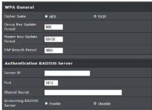
• WPA General Settings:
- Cipher Suite: By default, it is AES. Select either AES or TKIP cipher suites
- Group Key Update Period: By default, it's 3600 seconds. This time interval for rekeying GTK, broadcast/multicast encryption keys, in seconds. Entering the time-length is required.
Master Key Update Period: By default, it is 83499 seconds. This time interval for rekeying GTK, broadcast/multicast encryption keys, in seconds. Entering the time-length is required. - EAP Reauth Period: By default, it's 3600 seconds. Set WPA2 PMKID cache timeout period, after time out, the cached key will be deleted.
o Pre-Authentication: By default, it's "Disable". To Enable is use to speed up roaming before pre-authenticating IEEE 802.1X/EAP part of the full RSN authentication and key handshake before actually associating with a new AP.
- Radius Server Settings :
- IP Address: Enter the IP address of the Authentication RADIUS server.
o Port: By default, it's 1812. The port number used to communicate with RADIUS server.
TRENDnet User's Guide
TEW-739APBO
- Shared secret: A secret key used between system and RADIUS server. Supports 8 to 64 characters.
- Accounting RADIUS Server: Enable to set Account RADIUS server.
- WEP 802.1X: When WEP 802.1x Authentication is enabled, please refer to the following Dynamic WEP and RADIUS settings to complete configuration.

- Radius Server Settings:
- IP Address: Enter the IP address of the Authentication RADIUS server.
o Port: By default, it's 1812. The port number used to communicate with RADIUS server. - Shared secret: A secret key used between system and RADIUS server. Supports 8 to 64 characters.
- Accounting RADIUS Server: Enable to set Account RADIUS server.
Key Index: key index is used to designate the WEP key during data transmission. 4 different WEP keys can be entered at the same time, but only one is chosen. - WEP Key #: Enter HEX or ASCII format WEP key value; the system supports up to 4 sets of WEP keys.
○ WPA-PSK (or WPA2-PSK) : WPA (or WPA2) Algorithms, allows the system accessing the network by using the WPA-PSK protected access.
Wireless AP MAC Filter Setup
The administrator can allow or reject clients to access Repeater AP.
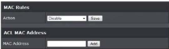
- MAC Filter Setup: By default, it's "Disable". Options are Disable, Only Deny List
• MAC or Only Allow List MAC.
Two ways to set MAC filter rules:
○ Only Allow List MAC: The wireless clients in the "Enable" list will be allowed to access the Access Point; All others or clients in the "Disable" list will be denied.
○ Only Deny List MAC: The wireless clients in the "Enable" list will be denied to access the Access Point; All others or clients in the "Disable" list will be allowed.
- MAC: Enter MAC address (e.g. aa:bb:cc:00:00:0a) and click "Add" button, then the MAC address should display in the "Enable" List.
There are a maximum of 20 clients allowed in this "Enable" List. The MAC addresses of the wireless clients can be added and removed to the list using the Add and Remove buttons. Click Apply button to activate your changes
Access Control
DMZ
DMZ is commonly work with the NAT functionality as an alternative of Virtual Server(Port Forwarding) while wanting all ports of DMZ host visible to Internet users. Virtual Server rules have precedence over the DMZ rule. In order to use a range of ports available to access to different internal hosts Virtual Server rules are needed.

- DMZ: By default, it's "Disable". Check Enable radial button to enable DMZ.
- IP Address: Enter IP address of DMZ host and only one DMZ host is supported.
TRENDnet User's Guide
TEW-739APBO
Click Save button to save your changes. Click Reboot button to activate your changes.
IP Filter Setup
Allows to create deny or allow rules to filter ingress or egress packets from specific source and/or to destination IP address on wired (LAN) or Wireless (WAN) ports. Filter rules could be used to filter unicast or multicast packets on different protocols as shown in the IP Filter Setup. Important to note that IP filter rules has precedence over Virtual server rules.
Please click on Advance -> IP Filter Setup and follow the below setting.

- Source Address/Mask: Enter desired source IP address and netmask; i.e. 192.168.2.10/32.
- Source Port: Enter a port or a range of ports as start:end; i.e. port 20:80
- Destination Address/Mask: Enter desired destination IP address and netmask; i.e. 192.168.1.10/32
- Destination Port: Enter a port or a range of ports as start:end; i.e. port 20:80
• In/Out: Applies to Ingress or egress packets
• Protocol: Supports TCP, UDP or ICMP. - Listen: Click Yes radial button to match TCP packets only with the SYN flag.
• Active: Deny to drop and Pass to allow per filter rules
• Interface: The interface that a filter rule applies
Click "Save" button to add IP filter rule. Total of 20 rules maximum allowed in the IP Filter List. All rules can be edited or removed from the List. Click Reboot button to activate your changes.
When you create rules in the IP Filter List, the prior rules maintain higher priority. To allow limited access from a subnet to a destination network manager needs to create allow rules first and followed by deny rules. So, if you just want one IP address to access the system via telnet from your subnet, not others, the Example 1 demonstrates it, not rules in the Example 2.
Example 1 : Create a higher priority rule to allow IP address 192.168.2.2 Telnet access from LAN port first, and deny Telnet access from remaining IP addresses in the same subnet.
Example 2: All Telnet access to the system from the IP addresses of subnet 192.168.2.x works with the rule 1 of Example 2. The rule 2 won't make any difference.
MAC Filter Setup
Create MAC filter rules to allow or deny unicast or multicast packets from limited number of MAC addresses. Note that MAC filter rules have precedence over IP Filter rules.
Please click on Advance -> MAC Filter Setup and follow the below setting.

- MAC Filter Rule: By default, it's "Disable". Options are Disabled, Only Deny List MAC or Only Allow List MAC. Click Save button to save your change.
Two ways to set the MAC Filter List:
○ Only Allow List MAC: The wireless clients in the MAC Filter List will be allowed to
TRENDnet User's Guide
TEW-739APBO
access to Access Point; All others will be denied.
○ Only Deny List MAC: The wireless clients in the MAC Filter List will be denied to access to Access Point; All others will be allowed.
- MAC Address: Enter MAC address (e.g. aa:bb:cc:00:00:0a) and click "Add" button, then the MAC address should display in the MAC Filter List.
There are a maximum of 20 clients allowed in this MAC Filter List. The MAC addresses of the wireless clients can be added and removed to the list using the Add and Delete buttons.
Click Reboot button to activate your changes
Virtual Server
"Virtual Server" can also referred to as "Port Forward" as well and used interchangeably. Resources in the network can be exposed to the Internet users in a controlled manner including on-line gaming, video conferencing or others via Virtual Server setup. Don't repeat ports' usage to avoid confusion.
Suppose you want to assign ports 21-25 to one FTP, Telnet and SMTP server (A in the example), and port 80 to another (B in the example). You assign the LAN IP addresses and the ISP assigns the WAN IP address. The NAT network appears as a single host on the Internet.

- Virtual Server: By Default, It's "Disable". Check Enable radial button to enable Virtual Server.
• Description: Enter appropriate message for resource sharing via Virtual Server. - Private IP: Enter corresponding IP address of internal resource to share.
- Protocol Type: Select appropriate sessions, TCP or UDP, from shared host via
multiple private ports.
- Private Port: A port or a range of ports may be specified as start:end; i.e. port 20:80
- Public Port: A port or a range of ports may be specified as start:end; i.e. port 20:80. Click "Add" button to add Virtual Server rule to List. Total of maximum 20 rules are allowed in this List. All rules can be edited or removed from the List. Click Reboot button to activate your changes.
While creating multiple Virtual Server rules, the prior rules have higher priority. The Virtual server rules have precedence over the DMZ one while both rules exist. Example 1 and 2 demonstrate proper usage of DMZ and Virtual Server rules.
- Example 1: All connections should be redirected to 192.168.2.12 while DMZ is enabled. Since Virtual Server rules have precedence over the DMZ rule all connections to TCP port 22 will be directed to TCP port 22 of 192.168.2.10 and remaining connections to port TCP 20\~80 will be redirected to port TCP 20\~80 of 192.168.2.11
- Example 2: All connections should be redirected to 192.168.2.12 while DMZ is enabled. Since Virtual Server rules have precedence over the DMZ rule all other connections to TCP port 20\~80 will be redirected to port 20\~80 of 192.168.2.11. The rule 2 won't take effect.
Bandwidth Control
Bandwidth control allows you to control the bandwidth going through the access point.

• Service: Select Enable to turn on bandwidth control through the access point.
- Mode: Select the bandwidth control mode to use through the access point.
- Upload: Enter the upload bandwidth speeds
- Download: Enter the download bandwidth speeds
TRENDnet User's Guide
TEW-739APBO
Routing
This section allows you to configure the routing of the access point.
- OSPF: Select Enable to enable OSPF setting

- RouterID: Select the ID to configure
• Network (WAN): Select to configure the WAN section, enter the area to assign
• Network (LAN): Select to configure the LAN section, enter the area to assign. - Distribute RIP over OSPF: Check this option to use RIP protocol
- RIP Settings
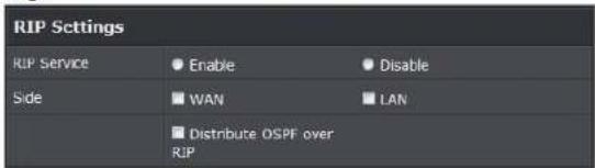
- RIP Service: Select Enable to use RIP protocol
- Side: Select the network section to apply RIP.
Status
This section breaks down into subsections of System Overview, Associated Clients Status, WDS Link Status, Extra Information and Event Log.
System Overview
Display detailed information of System, Network, LAN and Wireless in the System Overview page.
• Device Information: Display the information of the system.
| Device Information | |
| Mode | Repeater |
| Host Name | TEW-738AP90 |
| Host Description | 10dB@ Outdoor PoE Access Point |
| Firmware Version | V1.0.19 |
| Firmware Data | 2014/04/23 09:44:51 |
| Country | US |
| System Time | 2014/05/05 14:49:12 |
| System Up Time | 03:58:31 |
| ETH1 MAC | 00:22:AA:00:11:07 |
| ETH2 MAC | 00:22:AA:00:11:06 |
| Wireless MAC | 00:22:AA:00:11:08 |
○ Operating Mode: The mode currently in service.
o Host Name: The name of the system.
- Host Description: A description of the system.
o Firmware Version: The current installed firmware version.
o Firmware Date: The build time of installed firmware.
o Device Time: The current time of the system.
o System Up Time: The time period that system has been in service since last reboot.
o ETH1/ETH2MAC: Ethernet MAC address of the access point.
o Wireless MAC: Wireless MAC address of the access point
o CPU Loading: The CPU loading of the access point
o Memory Used: Memory usage of the access point.
TRENDnet User's Guide
TEW-739APBO
• LAN Information: Display total received and transmitted statistics on the LAN interface.
| LAN Information | |
| Ethernet Connection Type | Static IP |
| IP Address | 192.168.10.100 |
| IP Netmask | 255.255.255.0 |
| IP Gateway | 192.168.10.1 |
| DNS | |
- Ethernet Connection Type: The connection applied on the access point.
- IP Address: The management IP of system. By default, it's 192.168.2.254.
- IP Netmask: The network mask. By default, it's 255.255.255.0.
- IP Gateway: The gateway IP addresses and by default, it's 192.168.2.1.
o Primary DNS: The primary DNS server in service.
- Wireless Information: Display total received and transmitted statistics on available Virtual AP.
| Wireless Information | |
| WiFi | On |
| Band | 802.11b/g/n |
| Channel | 5 |
| Current Txpower | 28 dBm (630 mW) |
| Date Rate | Auto (300Mb/s) |
- WiFi: Wireless status of the access point.
- Band: Operating wireless band of the access point.
- Channel: Operating channel of the access point.
o Current Tx Power: Transmit power of the access point. - Data Rate: Current wireless data rate of the access point.
DHCP Client
Display detailed information of the access point's DHCP server.
| DHCP Server Status | |
| Service | Enable |
| Start IP | 192.168.10.101 |
| End IP | 192.168.10.254 |
| Default Gateway | 192.168.10.100 |
| DNS1 | 192.168.10.100 |
| DNS2 | |
| WINS | |
| Domain | |
| Lease Time | $6400 |
• Service: Status of access point's DHCP server
- Start IP: Starting IP address of access point's DHCP server
- End IP: Last IP address used on the access point's DHCP server
- Default Gateway: Assigned gateway address to the access point
• DNS1/2: Assigned DNS to the access point's DHCP server
- WINS: Assigned WINS to the access point's DHCP server
• Domain: Domain assigned to access point
- Lease Time: DHCP lease time of access point's DHCP server
| DHCP Client List | ||
| IP Address | MAC Address | Expired In |
| - | - | - |
- DHCP Client list: List of clients connected to the access point
TRENDnet User's Guide
TEW-739APBO
Extra Information
Users could pull out information such as Route table, ARP table, MAC table, Bridge table or STP available in the drop-down list from system. The "Refresh" button is used to retrieve latest table information.
| Extra Information | |||
| Information | Route Information | ||
| Route Information | |||
| Destination | Gateway | Netmask | Interface |
| 192.168.10.0 | 0.0.0.0 | 255.255.255.0 | bre0 |
| 239.0.0.0 | 0.0.0.0 | 255.0.0.0 | bre0 |
| 224.0.0.0 | 0.0.0.0 | 224.0.0.0 | bre0 |
| 0.0.0.0 | 192.168.10.1 | 0.0.0.0 | bre0 |
- Route table information: Select "Route table information" on the drop-down list to display route table. TEW-739APBO could be used as a L2 or L3 device. It doesn't support dynamic routing protocols such as RIP or OSPF. Static routes to specific hosts, networks or default gateway are set up automatically according to the IP configuration of system's interfaces. When used as a L2 device, it could switch packets and, as L3 device, it's capable of being a gateway to route packets inward and outward.
| Route Information | |||
| Destination | Gateway | Netmask | Interface |
| 192.168.10.0 | 0.0.0.0 | 255.255.255.0 | bre0 |
| 239.0.0.0 | 0.0.0.0 | 255.0.0.0 | bre0 |
| 224.0.0.0 | 0.0.0.0 | 224.0.0.0 | bre0 |
| 0.0.0.0 | 192.168.10.1 | 0.0.0.0 | bre0 |
- ARP table Information: Select "ARP Table Information" on the drop-down list to display ARP table. ARP associates each IP address to a unique hardware address (MAC) of a device. It is important to have a unique IP address as final destination to switch packets to.
| ARP Table Information | ||
| IP Address | MAC Address | Interface |
| 102.158.10.123 | 00:26:2d:5b:46:52 | bre0 |
- Bridge table information: Select "Bridge Table information" on the drop-down list to display bridge table. Bridge table will show Bridge ID and STP's Status on the each Ethernet bridge and its attached interfaces, the Bridge Port should be attached to some interfaces (e.g. eth2, ra0\~ra6 and wds0\~wds3).
| Bridge Table Information | |||
| Bridge Port | Bridge ID | STP Enabled | Interface |
| LAN | 8000.0022aa001106 | no | eth1 |
| eth0 | |||
| ath0 | |||
- Bridge MAC information: Select "Bridge MACs Information" on the drop-down list to display MAC table.
| Bridge MACs Table Information | |||
| Port | MAC Address | Local | Agcing Timer |
| VAP0 | 00:14:d1:c2:da:84 | no | 3.17 |
| LAN | 00:22:aa:00:11:06 | yes | 0.00 |
| WAN | 00:22:aa:00:11:07 | yes | 0.00 |
| VAP0 | 00:22:aa:00:11:08 | yes | 0.00 |
| WAN | 00:26:2d:5b:45:53 | no | 0.04 |
This table displays local MAC addresses associated with wired or wireless interfaces, but also remember non-local MAC addresses learned from wired or wireless interfaces. Ageing timers will be reset when existing MAC addresses in table are learned again or added when new MAC addresses are seen from wired or wireless interfaces as well. When time runs out for a particular entry, it will be pruned from the table. In that situation, switching packet to that particular MAC address will be dropped.
TRENDnet User's Guide
TEW-739APBO
Event Log
The Event log displays system events when system is up and running. Also, it becomes very useful as a troubleshooting tool when issues are experienced in system.
| Time | Facility | Severity | Message |
| 2013-07-0603:32:47 | System | Info | Authentication successful for admin from 192.168.10.123 |
• Time: The date and time when the event occurred.
- Facility: It helps users to identify source of events such "System" or "User"
- Severity: Severity level that a specific event is associated such as "info", "error", "warning", etc.
- Message: Description of the event.
Click Refresh button to renew the log, or click Clear button to clear all the record.
Associated Client List
List of all clients associated to the access point.
| # | MAC Address | RSSI | TX/RX Rate | TX/RX SEQ | TX/RX Bytes | Connect Time | Actions |
| No such device | |||||||
o MAC Address: Display MAC address of WDS peer.
o RSSI: Indicate the signal strength of the respective WDS links.
o TX/RX SEQ: Transmit and receive sequence.
o TX/RX Bytes: Transmit and receive bytes
Remote AP status
List the current status of the remote access point.
| ESSID | MAC Address | Signal/Noise | RSSI | Signal Quality, % | TX/RX Rate | Status |
| TRENDnet7380_2.4GHz | 0 / 0 | 0 | 0% | 0M / 0M | Normal |
o ESSID: SSID of remote access point
○ MAC Address: Display MAC address of WDS peer.
o RSSI: Indicate the signal strength of the respective WDS links.
o TX/RX SEQ: Transmit and receive sequence.
- TX/RX Bytes: Transmit and receive bytes
o Status: Display current association status of remote access point
System Management
Configure Management
Administrator could specify geographical location of the system via instructions in this page. Administrator could also enter new Root and Admin passwords and allow multiple login methods.
Please click System -> Management and follow the below settings.
• System Information
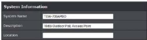
- System Name: Enter a desired name or use the default one.
- Description: Provide description of the system.
- Location: Enter geographical location information of the system. It helps administrator to locate the system easier.
- Admin Password:

TRENDnet User's Guide
TEW-739APBO
o New Password : Enter a new password if desired
- Check New Password: Enter the same new password again to check.
- Admin Login Methods:

○ Enable HTTP: Check to select HTTP Service.
o HTTP Port: The default is 80 and the range is between 1 \~ 65535.
- Enable HTTPS: Check to select HTTPS Service
- HTTPS Port: The default is 443 and the range is between 1 \~ 65535.
○ Enable Telnet: Check to select Telnet Service
o Telnet Port: The default is 23 and the range is between 1 \~ 65535.
○ Enable SSH: Check to select SSH Service
o SSH Port: The default is 22 and the range is between 1 \~ 65535.
- Ping Watchdog: The ping watchdog sets the TEW-739APBO Device to continuously ping a user defined IP address (it can be the internet gateway for example). If it is unable to ping under the user defined constraints, the TEW-739APBO device will automatically reboot. This option creates a kind of "fail-proof" mechanism.
Ping Watchdog is dedicated for continuous monitoring of the particular connection to remote host using the Ping tool. The Ping works by sending ICMP "echo request" packets to the target host and listening for ICMP "echo response" replies. If the defined number of replies is not received, the tool reboots the device.

○ Enable Ping Watchdog: control will enable Ping Watchdog Tool.
- IP Address To Ping: specify an IP address of the target host which will be monitored by Ping Watchdog Tool.
○ Ping Interval: specify time interval (in seconds) between the ICMP "echo requests" are sent by the Ping Watchdog Tool. Default is 300 seconds.
- Startup Delay: specify initial time delay (in seconds) until first ICMP "echo requests" are sent by the Ping Watchdog Tool. The value of Startup Delay should be at least 60 seconds as the network interface and wireless connection initialization takes considerable amount of time if the device is rebooted. Default is 300 seconds.
o Failure Count To Reboot: specify the number of ICMP "echo response" replies. If the specified number of ICMP "echo response" packets is not received continuously, the Ping Watchdog Tool will reboot the device.
Click Save button to save your changes. Click Reboot button to activate your changes
Without a valid certificate, users may encounter the following problem in IE7 when they try to access system's WMI (https://192.168.2.254). There will be a "Certificate Error", because the browser treats system as an illegal website.
TRENDnet User's Guide
TEW-739APBO

Click "Continue to this website" to access the system's WMI. The system's Overview page will appear.
Configure System Time
System time can be configured via this page and manual setting or via a NTP server is supported.
Please click on System -> Time Server and follow the below setting.

- Local Time: Display the current system time.
• NTP Client: To synchronize the system time with NTP server.
- Enable: Check to select NTP client.
- Default NTP Server: Select the NTP Server from the drop-down list.
○ Time Zone: Select a desired time zone from the drop-down list. - Daylight saving time: Enable or disable Daylight saving.
Click Save button to save your changes. Click Reboot button to activate your changes.
Configure SNMP Setup
SNMP is an application-layer protocol that provides a message format for communication between SNMP managers and agents. By enabling SNMP function, the administrator can obtain the system information remotely.
Please click on System -> SNMP Setup and follow the below setting.

• SNMP v2c Enable: Check to enable SNMP v2c.
TRENDnet User's Guide
TEW-739APBO

- ro community: Set a community string to authorize read-only access.
- rw community: Set a community string to authorize read/write access.
- SNMP v3 Enable: Check to enable SNMP v3. SNMPv3 supports the highest level SNMP security.

- SNMP ro user: Set a community string to authorize read-only access.
o SNMP ro password: Set a password to authorize read-only access.
o SNMP rw user: Set a community string to authorize read/write access. - SNMP rw password: Set a password to authorize read/write access.
- SNMP Trap: Events such as cold start, interface up & down, and association & disassociation will report to an assigned server.
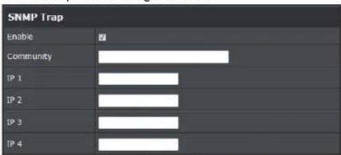
o Community: Set a community string required by the remote host computer that
will receive trap messages or notices send by the system.
- IP: Enter the IP addresses of the remote hosts to receive trap messages. Click Save button to save changes and click Reboot button to activate.
Enable UPNP
Enable UPNP protocol on the access point.

• Service:
○ Enable: Select to enable UPNP through the access point
○ Disable: Select to disable UPNP
Backup / Restore and Reset to Factory
Backup current configuration, restore prior configuration or reset back to factory default configuration can be executed via this page.
Please click on Utilities -> Profile Setting and follow the below setting.

- Save Settings to PC: Click Save to save current access point configuration settings to a computer.
- Load Settings from PC: Click Browse button to locate a configuration file to restore, and then click Upload button to upload.
- Reset To Factory Default: Click Default button to reset back to the factory default settings and expect Successful loading message. Then, click Reboot button to activate.
TRENDnet User's Guide
TEW-739APBO
Firmware Upgrade
Firmware is the main software image that system needs to respond to requests and to manage real time operations. Firmware upgrades are sometimes required to include new features or bugs fix. It takes around 2 minutes to upgrade due to complexity of firmware. To upgrade system firmware, click Browse button to locate the new firmware, and then click Upgrade button to upgrade.
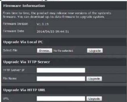
- Firmware Version: Access point's current firmware version
• Firmware Date: Firmware date of access point - Select File: Click Browse button to locate a configuration file to restore, and then click Upgrade button to upload.
- TFTP Server IP: Enter the IP address of the TFTP server to use for firmware upgrade
- File: Enter the location of the firmware file to use, and then click Upgrade button to upload.
- URL: Enter the URL to use to upgrade access point's firmware. Then, click Reboot button to activate.
Network Utility
The administrator can diagnose network connectivity via the PING and TRACEROUTE utility.
Please click on Utilities -> Network Utility and follow the below setting
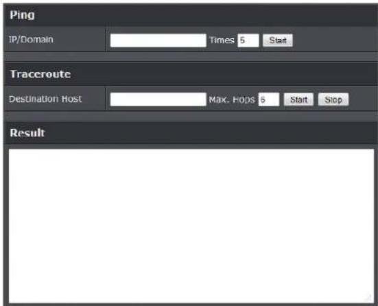
- Ping: This utility will help ping other devices on the network to verify connectivity. Ping utility, using ICMP packets, detects connectivity and latency between two network nodes. As result of that, packet loss and latency time are available in the Result field while running the PING test.
Destination IP/Domain: Enter desired domain name, i.e. www.google.com, or IP address of the destination, and click ping button to proceed. The ping result will be shown in the Result field. - Count: By default, it's 5 and the range is from 1 to 50. It indicates number of connectivity test.
- Traceroute: Allows tracing the hops from the TEW-739APBO device to a selected outgoing IP address. It should be used for the finding the route taken by ICMP packets across the network to the destination host. The test is started using the Start button, click Stop button to stopped test
- Destination Host: Specifies the Destination Host for the finding the route taken by ICMP packets across the network.
o MAX Hop: Specifies the maximum number of hops( max time-to-live value) traceroute will probe.
TRENDnet User's Guide
TEW-739APBO
Reboot
This function allows user to restart system with existing or most current settings when changes are made. Click Reboot button to proceed and take around three minutes to complete.
Reboot
Sometimes it may be necessary to reboot the system if it begins working improperly. Rebooting the system will not delete any of your configuration settings. Click reboot button to reboot the system.
Reboot
A reminder will be available for remaining time to complete. If power cycle is necessary, please wait till completion of the reboot process.
Please Wait
System is restarting, please wait for 35 seconds.
Mounting bracket installation
Package contents
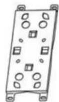
Wall mount x 1

Stainless tie back straps x 2

Wood Screw x 4 &
Wood/Gyprock Plug x 4

M5x10 Screw x 4


Washer x 4

Spring Washer x 4
TRENDnet User's Guide
TEW-739APBO
Wall mount bracket
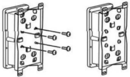
Align the mounting triangle to the back of the access point. Securely tighten the mounting triangle by using the M5x10 screws and washers.

Position the provided mounting bracket to the desired location and mount as shown in the above image using the provided wood screws and plugs.
Pole mount bracket

Insert and fasten the provided clamps to the pole as shown in the above image using the provided screw washers, spring washers and nuts.
TRENDnet User's Guide
Appendix
Appendix
Windows TCP/IP Settings
■ Windows XP
- Click Start -> Settings -> Control Panel, and then "Control Panel" window appears. Click on "Network Connections", and then "Network Connections" window appears.

- Click right on "Local Area Connection", and select Properties.

- In "Local Area Connection Properties" window, select "Internet Protocol (TCP/IP)" and click on Properties button.
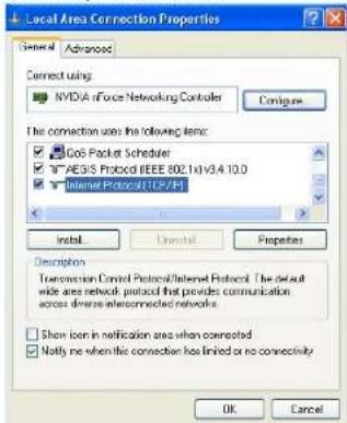
- Select "Use the following IP address", and type in IP address : 192.168.2.100
TRENDnet User's Guide
Appendix
Subnet mask : 255.255.255.0
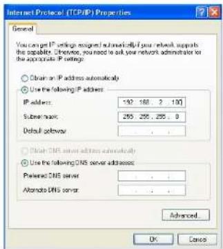
Enabling UPnP in Windows XP
- Open the "Add/Remove Programs" control panel, and then click on "Add/Remove Windows Components" in the sidebar. Scroll down and find "Networking Services", highlight it, and then click Details.

- In the "Networking Services" window, ensure that the "Internet Gateway Device" and "UPnP User Interface" options are checked. If they are not, check it to enable them, as shown below, and click OK to continue.
TRENDnet User's Guide
Appendix

- Next, in the "Control panel", open the "Administrative Tools" and then open "Services". Scroll down until you find the "SSDP Discovery Interface". If the Status is not Started, double-click on SSDP Discovery Interface to open the service properties. Change the startup type to Automatic, then close the properties. Now, right-click on SSDP Discovery Services, and choose Start from the pop-up menu. The SSDP Discovery Service will then be running and start each time you boot.
- After enabling UPnP and starting the SSDP Discovery Service, it may take few minutes for the "TEW-675APBO/ TEW-739APBO" to be discovered and appear in your "My Network Places".
TRENDnet User's Guide
Warranty
Limited Warranty
TRENDnet warrants its products against defects in material and workmanship, under normal use and service, for the following lengths of time from the date of purchase.
TEW-739APBO - 3 Years Warranty
AC/DC Power Adapter, Cooling Fan, and Power Supply carry 1 year warranty.
If a product does not operate as warranted during the applicable warranty period, TRENDnet shall reserve the right, at its expense, to repair or replace the defective product or part and deliver an equivalent product or part to the customer. The repair/replacement unit's warranty continues from the original date of purchase. All products that are replaced become the property of TRENDnet. Replacement products may be new or reconditioned. TRENDnet does not issue refunds or credit. Please contact the point-of-purchase for their return policies.
TRENDnet shall not be responsible for any software, firmware, information, or memory data of customer contained in, stored on, or integrated with any products returned to TRENDnet pursuant to any warranty.
There are no user serviceable parts inside the product. Do not remove or attempt to service the product by any unauthorized service center. This warranty is voided if (i) the product has been modified or repaired by any unauthorized service center, (ii) the product was subject to accident, abuse, or improper use (iii) the product was subject to conditions more severe than those specified in the manual.
Warranty service may be obtained by contacting TRENDnet within the applicable warranty period and providing a copy of the dated proof of the purchase. Upon proper submission of required documentation a Return Material Authorization (RMA) number will be issued. An RMA number is required in order to initiate warranty service support for all TRENDnet products. Products that are sent to TRENDnet for RMA service must have the RMA number marked on the outside of return packages and sent to TRENDnet prepaid, insured and packaged appropriately for safe shipment. Customers shipping from outside of the USA and Canada are responsible for return shipping fees. Customers shipping from outside of the USA are responsible for custom charges, including but not limited to, duty, tax, and other fees.
WARRANTIES EXCLUSIVE: IF THE TRENDNET PRODUCT DOES NOT OPERATE AS WARRANTED ABOVE, THE CUSTOMER'S SOLE REMEDY SHALL BE, AT TRENDNET'S OPTION, REPAIR OR REPLACE. THE FOREGOING WARRANTIES AND REMEDIES ARE EXCLUSIVE AND ARE IN LIEU OF ALL OTHER WARRANTIES, EXPRESSED OR IMPLIED,
EITHER IN FACT OR BY OPERATION OF LAW, STATUTORY OR OTHERWISE, INCLUDING WARRANTIES OF MERCHANTABILITY AND FITNESS FOR A PARTICULAR PURPOSE. TRENDNET NEITHER ASSUMES NOR AUTHORIZES ANY OTHER PERSON TO ASSUME FOR IT ANY OTHER LIABILITY IN CONNECTION WITH THE SALE, INSTALLATION MAINTENANCE OR USE OF TRENDNET'S PRODUCTS.
TRENDNET SHALL NOT BE LIABLE UNDER THIS WARRANTY IF ITS TESTING AND EXAMINATION DISCLOSE THAT THE ALLEGED DEFECT IN THE PRODUCT DOES NOT EXIST OR WAS CAUSED BY CUSTOMER'S OR ANY THIRD PERSON'S MISUSE, NEGLECT, IMPROPER INSTALLATION OR TESTING, UNAUTHORIZED ATTEMPTS TO REPAIR OR MODIFY, OR ANY OTHER CAUSE BEYOND THE RANGE OF THE INTENDED USE, OR BY ACCIDENT, FIRE, LIGHTNING, OR OTHER HAZARD.
LIMITATION OF LIABILITY: TO THE FULL EXTENT ALLOWED BY LAW TRENDNET ALSO EXCLUDES FOR ITSELF AND ITS SUPPLIERS ANY LIABILITY, WHETHER BASED IN CONTRACT OR TORT (INCLUDING NEGLIGENCE), FOR INCIDENTAL, CONSEQUENTIAL, INDIRECT, SPECIAL, OR PUNITIVE DAMAGES OF ANY KIND, OR FOR LOSS OF REVENUE OR PROFITS, LOSS OF BUSINESS, LOSS OF INFORMATION OR DATE, OR OTHER FINANCIAL LOSS ARISING OUT OF OR IN CONNECTION WITH THE SALE, INSTALLATION, MAINTENANCE, USE, PERFORMANCE, FAILURE, OR INTERRUPTION OF THE POSSIBILITY OF SUCH DAMAGES, AND LIMITS ITS LIABILITY TO REPAIR, REPLACEMENT, OR REFUND OF THE PURCHASE PRICE PAID, AT TRENDNET'S OPTION. THIS DISCLAIMER OF LIABILITY FOR DAMAGES WILL NOT BE AFFECTED IF ANY REMEDY PROVIDED HEREIN SHALL FAIL OF ITS ESSENTIAL PURPOSE.
Governing Law: This Limited Warranty shall be governed by the laws of the state of California.
Some TRENDnet products include software code written by third party developers. These codes are subject to the GNU General Public License ("GPL") or GNU Lesser General Public License ("LGPL").
Go to http://www.trendnet.com/gpl or http://www.trendnet.com Download section and look for the desired TRENDnet product to access to the GPL Code or LGPL Code. These codes are distributed WITHOUT WARRANTY and are subject to the copyrights of the developers. TRENDnet does not provide technical support for these codes. Please go to http://www.gnu.org/licenses/gpl.txt or http://www.gnu.org/licenses/lgpl.txt for specific terms of each license.
2014/10/08
TRENDNET®
Product Warranty Registration
Please take a moment to register your product online. Go to TRENDnet's website at http://www.trendnet.com/register
TRENDnet
20675 Manhattan Place
Torrance, CA 90501. USA
Copyright ©2014. All Rights Reserved. TRENDnet.
- N300 OUTDOOR POE ACCESS POINT
- TRENDNET USER'S GUIDE
- TABLE OF CONTENTS
- CONTENTS
- CPE + AP MODE CONFIGURATION ....50
- SYSTEM MANAGEMENT 68
- MOUNTING BRACKET INSTALLATION....73
- APPENDIX....75
- TEW-739APBO
- INTRODUCTION
- PERFORMANCE
- ANTENNAS
- MULTI-MODE SUPPORT
- N300 WIRELESS (2.4 GHZ)
- OUTDOOR RATED
- DISTANCE RATING
- POWER OVER ETHERNET (POE)
- LOGS
- ENCRYPTED WIRELESS
- MULTIPLE SSIDS
- COMPATIBILITY
- MOUNTING HARDWARE
- PACKAGE CONTENTS
- HARDWARE FEATURE
- BOTTOM PANEL
- LEDS
- RESET BUTTON (UNSCREW CAP)
- REAR PANEL
- PRODUCT BENEFIT
- INSTALLATION CONSIDERATIONS
- INSTALLATION
- CONFIGURATION
- APPLICATIONS
- OPERATING MODE
- AP MODE (INCLUDING ACCESS POINT + WDS)
- EXAMPLE 2: ACCESS POINT WITH WDS
- WDS MODE (PURE WDS)
- CLIENT BRIDGE + UNIVERSAL REPEATER MODE
- CPE + AP MODE (ROUTER CLIENT + ACCESS POINT)
- WEB MANAGEMENT INTERFACE INSTRUCTIONS
- STEP
- EXAMPLE OF SEGMENT
- AP MODE CONFIGURATION
- EXTERNAL NETWORK CONNECTION
- NETWORK REQUIREMENT
- CONFIGURE LAN IP
- 802.1D SPANNING TREE
- WIRELESS LAN NETWORK
- WIRELESS GENERAL SETUP
- WIRELESS ADVANCED SETUP
- WIRELESS WMM QOS SETUP
- CREATE VIRTUAL AP (VAP)
- VIRTUAL AP OVERVIEW
- VIRTUAL AP SETUP
- WEP 802.1X
- WIRELESS MAC FILTER SETUP
- WIRELESS NETWORK EXPANSION
- SYSTEM STATUS
- SYSTEM OVERVIEW
- ASSOCIATED CLIENTS STATUS
- SHOW WDS LINK STATUS
- EXTRA INFORMATION
- EVENT LOG
- WDS MODE CONFIGURATION
- WDS SETUP
- WDS LINK STATUS
- REPEATER MODE
- SITE SURVEY
- REPEATER AP SETUP
- WPA GENERAL SETTINGS
- RADIUS SERVER SETTINGS
- CREATE WIRELESS PROFILE
- BANDWIDTH CONTROL
- CONFIGURE SNMP SETUP
- CONFIGURE TIME POLICY
- DHCP CLIENT
- ASSOCIATED CLIENT LIST
- REMOTE AP STATUS
- CPE + AP MODE CONFIGURATION
- CONFIGURE CPE SETUP
- DYNAMIC IP
- CONFIGURE DDNS SETUP
- CONFIGURE STATIC IP ADDRESS
- ACCESS POINT ASSOCIATION WIRELESS GENERAL SETUP
- WEP 802.1X: WHEN WEP 802.1X AUTHENTICATION IS ENABLED, PLEASE REFER TO THE FOLLOWING DYNAMIC WEP AND RADIUS SETTINGS TO COMPLETE CONFIGURATION
- AP SETUP
- WIRELESS AP MAC FILTER SETUP
- ACCESS CONTROL
- DMZ
- IP FILTER SETUP
- MAC FILTER SETUP
- VIRTUAL SERVER
- ROUTING
- STATUS
- SYSTEM MANAGEMENT
- CONFIGURE MANAGEMENT
- CONFIGURE SYSTEM TIME
- ENABLE UPNP
- BACKUP / RESTORE AND RESET TO FACTORY
- FIRMWARE UPGRADE
- NETWORK UTILITY
- REBOOT
- PLEASE WAIT
- MOUNTING BRACKET INSTALLATION
- APPENDIX
- WINDOWS TCP/IP SETTINGS
- WINDOWS XP
- ENABLING UPNP IN WINDOWS XP
- WARRANTY
- LIMITED WARRANTY
- TRENDNET®
- PRODUCT WARRANTY REGISTRATION
Brand : TRENDNET
Model : TEW-739APBO
Category : Access Point