
Eliminator 125 (2007) - Motorcycle MITSUBISHI - Free user manual and instructions
Find the device manual for free Eliminator 125 (2007) MITSUBISHI in PDF.


| Product Type | Motorcycle |
| Brand | Mitsubishi |
| Model | Eliminator 125 (2007) |
| Engine Displacement | 124 cc |
| Engine Type | 4-stroke, single cylinder, air-cooled |
| Max Power | 10.5 hp (7.8 kW) @ 8,500 rpm |
| Max Torque | 9.5 Nm @ 7,000 rpm |
| Transmission | 5-speed manual |
| Final Drive | Chain |
| Frame Type | Steel tube, double cradle |
| Front Suspension | Telescopic fork, 33 mm |
| Rear Suspension | Dual shock absorbers, adjustable preload |
| Front Brake | Single disc, 240 mm (optional ABS) |
| Rear Brake | Drum brake, 130 mm |
| Tire Size (Front) | 90/90-18 |
| Tire Size (Rear) | 110/90-16 |
| Wheelbase | 1,470 mm (57.9 in) |
| Seat Height | 710 mm (28.0 in) |
| Fuel Capacity | 12 L (3.2 gal) |
| Dry Weight | 125 kg (276 lb) |
| Overall Length | 2,200 mm (86.6 in) |
| Overall Width | 780 mm (30.7 in) |
| Overall Height | 1,100 mm (43.3 in) |
| Manual Format | PDF, 385 pages, English |
Frequently Asked Questions - Eliminator 125 (2007) MITSUBISHI
User questions about Eliminator 125 (2007) MITSUBISHI
0 question about this device. Answer the ones you know or ask your own.
Ask a new question about this device
Download the instructions for your Motorcycle in PDF format for free! Find your manual Eliminator 125 (2007) - MITSUBISHI and take your electronic device back in hand. On this page are published all the documents necessary for the use of your device. Eliminator 125 (2007) by MITSUBISHI.
USER MANUAL Eliminator 125 (2007) MITSUBISHI
natural_image
Side profile of a black Kawasaki motorcycle with visible engine and wheelbars (no text or symbols)Motorcycle ServiceManual
QuickReferenceGuide
| GeneralInformation1 | |
| PeriodicMaintenance2 | |
| FuelSystem3 | |
| EngineTopEnd4 | |
| Clutch5 | |
| EngineLubricationSystem | 6 |
| EngineRemoval/Installation | 7 |
| Crankshaft/Transmission | 8 |
| Wheels/Tires | 9 |
| FinalDrive | 10 |
| Brakes | 11 |
| Suspension | 12 |
| Steering | 13 |
| Frame | 14 |
| ElectricalSystem | 15 |
| Appendix | 16 |
This quick reference guidewill assist you in locating adesired topic or procedure.
- Bendthepagesbacktomatchthe blacktabofthedesiredchapternumberwiththeblacktabontheedgeateachtableofcontentspage.
•Refertothesectionaltableofcontents fortheexactpagestolocatethespecifictopicrequired.
Motorcycle ServiceManual
Allrightsreserved.Nopartsofthispublicationmaybereproduced,storedinaretrievalsystem,or transmittedinanyformorbyanymeans,electronicmechanicalphotocopying,recordingorotherwise, withoutthepriorwrittenpermissionofQualityDivision/ConsumerProducts&MachineryCompany/Kawasaki HeavyIndustries,Ltd.,Japan.
Noliability can be accepted for any inaccuracies or missions in this publication, although every possible care has been taken to make it as complete and accurate as possible.
The right is reserved to make changes at any time without prior notice and without incurring an obligation to make such changestoproducts manufactured previously. See your Motorcycle dealer forthelatest information on product improvements incorporated after this publication.
All information contained in this publication is based on the latest product information available at the time of publication. Illustrationsandphotographsinthispublicationareintendedforreferenceuseonlyandmay notdepictactualmodelcomponentparts.
LISTOFABBREVIATIONS
| Aampere(s) | lbpound(s) | ||
| ABDCafter | bottomdeadcenter | m | meter(s) |
| AC | alternatingcurrentmin | minute(s) | |
| ATDcafter | topdeadcenter | N | newton(s) |
| BBDCbefore | bottomdeadcenterPapascal(s) | ||
| BDCbottom | deadcenterPShorsepower | ||
| BTDC | before top dead center | psi | pound(s) per square inch |
| °C | degree(s) Celsius | r | revolution |
| DC | direct current | rpm | revolution(s) per minute |
| F | farad(s) | TDC | top dead center |
| °F | degree(s) Fahrenheit | TIR | total indicator reading |
| ft | foot, feet | V | volt(s) |
| g | gram(s) | W | watt(s) |
| h | hour(s) | Ω | ohm(s) |
| L | liter(s) |
Read OWNER'S MANUAL before operating.
EMISSIONCONTROLINFORMATION
Toprotecttheenvironmentinwhichwealllive,Kawasakihasincorporatedcrankcaseemission(1)andexhaustemission(2)controlsystemsincompliancewithapplicableregulationsof theUnitedStatesEnvironmentalProtectionAgencyandCaliforniaAirResourcesBoard.Additionally,Kawasakihasincorporatedanevaporativeemissioncontrolsystem(3)incompliance withapplicableregulationsoftheCaliforniaAirResourcesBoardonvehiclessoldinCalifornia only.
- CrankcaseEmissionControlSystem
This system eliminates the lease of crank case vapors into the atmosphere. Instead, the vapors are routed through an oil separator to the inlet side of the engine. While the engine is operating, the vapors are drawn into combustion chamber, where they are burned along with the fuel and air supplied by the carburetionsystem.
- ExhaustEmissionControlSystem
This system reduces the amount of pollutants discharged into the atmosphere by the exhaust of this motorcycle. The fuel, ignition, and exhaust system so this motorcycle have been carefully designed and constructed to ensure an efficient engine with low exhaust pollutants levels.
TheexhaustsystemofthismodelmotorcyclemanufacturedprimarilyforsaleinCaliforniain-cludesacatalyticconvertersystem.
- Evaporative Emission Control System
Vaporscausedbyfuelevaporationinthefuelsystemarenotventedintotheatmosphere.Instead,fuelvaporsareroutedintotherunningenginetobeburned,orstoredinacanisterwhen theengineisstopped.Liquidfueliscaughtbyavaporseparatorandreturnedtothefueltank.
TheCleanAirAct, which is the Federal law covering motor vehicle pollution, contains what is commonly referred to the Act's "tampering provisions."
"Sec.203(a)Thefollowingactsandthecausingthereofareprohibited...
(3)(A)foranypersontoremoveorrenderinoperativeanydeviceorelementofdesigninstalled onorinamotorvehicleormotorvehicleengineincompliancewithregulationsunderthis titlepriortoitssaleanddeliverytotheultimatepurchaser,orforanymanufacturerordealer knowinglytoremoveorrenderinoperativeanysuchdeviceorelementofdesignaftersuch saleanddeliverytotheultimatepurchaser.
(3)(B)foranypersonengagedinthebusinessofrepairing,servicing,selling,leasing,ortrading motorvehiclesormotorvehicleengines,orwhooperatesafleetofmotorvehiclesknowinglytoremoveorrenderinoperativeanydeviceorelementofdesigninstalleddonorina motorvehicleormotorvehicleengineincompliancewithregulationsunderthistitlefollowingitssaleanddeliverytotheultimatepurchaser..."
NOTE
○ The phrase "remove or render inoperative any device or element of design" has been generally interpreted as follows:
- Tamperingdoesnotincludethetemporaryremovalorrenderinginoperativeofdevicesorelementsofdesigninordertoperformmaintenance.
- Tamperingcouldinclude:
a. Maladjustmentofvehiclecomponentssuchthattheemissionstandardsareexceeded.
b. Use of replacement parts or accessories which adversely affect the performance ordurability of the motorcycle.
c.Additionofcomponentsoraccessoriesthatresultinthevehicleexceedingthestandards.
d. Permanently removing, disconnecting, or rendering in operative any component or element of design of the emission control systems.
WERECOMMENDTHATALLDEALERSOBSERVETHESEPROVISIONSOFFEDERALLAW, THEVIOLATIONOFWHICHISPUNISHABLEBYCIVILPENALTIESNOTEXCEEDING \$10,000PERVIOLATION.
TAMPERINGWITHNOISECONTROLSYSTEMPROHIBITED
Federallawprohibitsthefollowingactsorthecausingthereof:(1)Theremovalorrendering inoperativebyanypersonotherthanforpurposesofmaintenance,repair,orreplacement,ofany deviceorelementofdesignincorporatedintoanynewvehicleforthepurposeofnoisecontrol priortoitssaleordeliverytotheultimatepurchaserorwhileitisinuse,or(2)theuseofthe vehicleaftersuchdeviceorelementofdesignhasbeenremovedorrenderedinoperativeby anyperson.
Amongthoseactspresumedtoconstitutetamperingaretheactslistedbelow:
- Replacementoftheoriginalexhaustsystemormufflerwithaccomponentnotincompliance withFederalregulations.
- Removalofthemuffler(s)oranyinternalportionofthemuffler(s).
- Removaloftheairboxorairboxcover.
- Modificationstothemuffler(s)orairinletsystembycutting,drilling,orothermeansifsuch modificationsresultinincreasednoiselevels.
Foreword
Thismanualisdesignedprimarilyforuseby trainedmechanicsinaproperlyequippedshop. However, it contains enough detail and basic information to make useful to the owner who desire to perform his own basic maintenance and repair work. Abasicknowledge of mechanics, the proper use of tools, and workshop procedures must be understood in order to carry out maintenance and repairs satisfactorily. Whenever the owner has insufficient experience or doubt this ability to do the work, all adjustments, maintenance, and repair should be carried out only by qualified mechanics.
Inordertoperformtheworkefficiently and toavoidcostlymistakes,readthetext,thoroughlyfamiliarizeyourselfwiththeprocedures beforestartingwork,andthendotheworkcarefullyinacleanarea.WhenIVERSpecialtoolsorequipmentarespecified,donotusemakeshift toolsorequipment.Precisionmeasurements canonlybemadeiftheproperinstrumentsare used,andtheuseofsubstitutetoolsmayadverselyaffectsafeoperation.
Forthedurationofthewarrantyperiod, werecommendthatallrepairsandscheduled maintenancebeperformedinaccordancewith thisservicemanual.Anyownermaintenanceor repair procedure not performed in accordance withthismanualmayvoidthewarranty. Togetthelongestlifeoutofyourvehicle:
- FollowthePeriodicMaintenanceChartintheServiceManual.
- Be alert for problems and non-scheduled maintenance.
- UsepropertoolsandgenuineKawasakiMotorcycleparts. Specialtools, gauges, and testersthatarenecessarywhen servicing Kawasakimotorcyclesareintroduced by the Service Manual. Genuine parts provided as sparepartsarelistedinthePartsCatalog.
- Follow the procedures in this manual carefully. Don't take shortcuts.
- Remembertokeepcompleterecordsof maintenanceandrepairwithdatesandanynew partsinstalled.
HowtoUseThisManual
In this manual, the product is divided into its majors systems and the these systems makeup them an ual's chapters. The Quick Reference
Guideshowsyoualloftheproduct'ssystem andassistsinlocatingtheirchapters. Each chapterinturnhasitsowncomprehensiveTableofContents.
Forexample, if you want ignition coil information, use the Quick Reference Guide to locate the Electrical System chapter. Then, use the Table of Contents on the first page of the chapter to find the Ignition Coil section.
Whenever you see these WARNING and CAUTION symbols, heed their instructions! Alwaysfollowsafeoperatingandmaintenance practices.
WARNING
This warningsymbolidentifiesspecial instructionsorprocedureswhich,ifnot correctlyfollowed,couldresultinpersonalinjuryorlossoflife.
CAUTION
Thiscautionsymbolidentifiesspecial instructionsorprocedureswhich,ifnot strictlyobserved,couldresultindam- agetoordestructionofequipment.
This manual contains four more symbols (in addition to WARNING and CAUTION) which will help you distinguish different types of information.
NOTE
○This note symbol indicates points of particular interest form more efficient and convenient operation.
- Indicatesaproceduralsteporworktobe done.
○Indicatesaproceduralsub-steporhowtodo the work of the procedural step it follows. It alsoprecedesthetextofaNOTE.
★Indicatesaconditionalsteporwhatactionto takebasedontheresultsofthetestorinspection in the procedural step or sub-step it follows.
In most chapters an exploded view illustration of the system components follow the Table of Contents. In these illustrations you will find the instructions indicating which parts require specified tightening torque, oil, grease or a locking agent during assembly.
GeneralInformation
TableofContents
Before Servicing 1-2
Model Identification.... 1-7
General Specifications.... 1-9
Technical Information-DC-CDI (Direct Current-Capacitor Discharge Ignition System).... 1-13
Technical Information-Coasting Enricher 1-20
Unit Conversion Table 1-22
1-2GENERALINFORMATION
BeforeServicing
Beforestartingtopermaninspectionserviceorcarryoutadisassemblyandreassemblyoperation on a motorcycle, read the precautions given below. To facilitate actual operations, notes, illustrations, photographs, cautions, and detailed descriptions have been included in each chapter wherever necessary. This section explains the items that require particular attention during the removal and reinstallationordisassemblyandreassemblyofgeneralparts.
Especiallynotethefollowing:
BatteryGround
Beforecompletinganyserviceonthemotorcycle, disconnectthebatterycablesfromthebatterytopreventtheenginefromaccidentallyturningover.Disconnecttheground cable(−)firstandthenthepositive(+).Whencompleted withtheservice,firstconnectthepositive(+)cabletothe positive(+)terminalofthebatterythenthenegative(−)cabletothenegativeterminal.
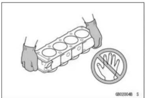
EdgesofParts
Liftlargeorheavypartswearingglovestopreventinjury frompossiblesharpedgesontheparts.
Solvent
Useahighflushpointsolventwhencleaningparts.High flushpointsolventshouldbeusedaccordingtodirections ofthesolventmanufacturer.
Cleaningvehiclebeforedisassembly
Cleanthevehiclethoroughlybeforedisassembly.Dirtor otherforeignmaterialsenteringintosealedareasduringveh-cledisassemblycancauseexcessivewearanddecrease performanceofthevehicle.

natural_image
Illustration of a hand holding a cylindrical engine block with a no-handled hand symbol nearby (no text or labels)

natural_image
Line drawing of a motorcycle with hands adjusting the wheel (no text or symbols)BeforeServicing
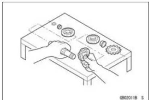
ArrangementandCleaningofRemovedParts
Disassembledpartsareeasytoconfuse.Arrangethe partsaccordingtotheorderthepartsweredisassembled andcleanthepartsinorderpriortoassembly.
StorageofRemovedParts
After all the parts including subassembly part have been cleaned, store the parts in a clean area. Put a clean cloth or plastics sheet over the part stop protect from any foreign material that may collect before assembly.
Inspection
Reuseofwornordamagedpartsmayleadtoseriousaccident. Visuallyinspectremovedpartsforcorrosion,discoloration,orotherdamage. Refertotheappropriatesections ofthismanualforservicelimitsonindividualparts. Replace thepartsifanydamagehasbeenfoundorifthepartisbeyonditsservicelimit.
ReplacementParts
ReplacementpartsmustbeKAWASAKIgenuineor recommendedbyKAWASAKI.Gaskets,O-rings,oilseals, greaseseals,circlipsorcotterpinsmustbereplacedwith newoneswheneverdisassembled.
AssemblyOrder
Inmostcasesassemblyorderisthereverseofdisassembly,however,ifassemblyorderisprovidedinthisService Manual,followtheproceduresgiven.

natural_image
Technical line drawing of a mechanical assembly with gears and components (no text or symbols)
natural_image
Technical line drawing of a mechanical assembly with gears and components (no text or symbols)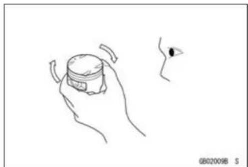
natural_image
Line drawing of a hand holding a small container with a small inset showing an eye (no text or symbols)
natural_image
Line drawing of hands operating a mechanical device with gears and a handle (no text or symbols)BeforeServicing
TighteningSequence
Generally, when installing apart with several bolts, nuts, or screws, start them all in their holes and tightent hem to as nugfit. Thentightenthem according to the specified sequence to prevent casewar page or deformation which can lead to malfunction. Conversely when loosening the bolts, nuts, or screws, first loosen allof them by about a quarter turn and then removethem. If these specified tightening sequence is not indicated, tightent he fasteners alternating diagonally.
Tightening Torque
Incorrect torque applied to a bolt, nut, or screw may lead to serious damage. Tighten fastener stothespecified torque using a good quality torque wrench. Often, the tightening sequence is followed twice - initial tightening and final tightening with torque wrench.
Force
Usecommonsenseduringdisassemblyandassembly, excessive force can cause expensive or hard to repair damage. Whennecessary,removescrewsthathaveanon-permanentlockingagentappliedusinganimpactdriver. Useaplastic-facedmalletwhenevertappingisnecessary.
Gasket, O-ring
Hardening, shrinkage, or damage of both gaskets and O-ringsafterdisassembly can reduce sealing performance. Remove old gaskets and clean these sealing surfaces thoroughly so that nogasket material or other material remains. Install new gaskets and replace used O-rings when re-assembling.
LiquidGasket,LockingAgent
For application that require Liquid Gasketora Locking agent, clean the surfaces so that no oil residue remains before applying liquid gasketor locking agent. Donot apply them excessively. Excessive application can clog oil passages and causes serious damage.


natural_image
Line drawing of hands using a tool to measure a cylindrical object, no text or symbols present
natural_image
Line drawing of a mechanical component being adjusted by a hand (no text or symbols)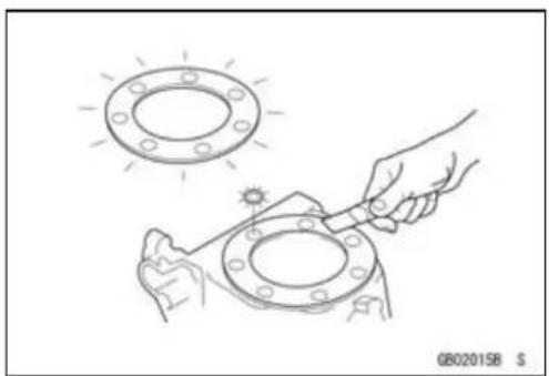
natural_image
Line drawing of two hands adjusting a flange with a sun icon, no text or symbols present
natural_image
Illustration of a hand using a tool to connect components in a mechanical housing, with a no-smoking symbol nearby (no text or labels)BeforeServicing
Press
Foritemssuchasbearingsoroilsealsthatmustbe pressedintoplace,applysmallamountofoiltothecontactarea.Besuretomaintainproperalignmentanduse smoothmovementswheninstalling.
BallBearingandNeedleBearing
Donotremovepressedballorneedleunlessremovalis absolutelynecessary.Replacewithnewoneswhenever removed.Pressbearingswiththemanufacturerandsize marksfacingout.Pressthebearingintoplacebyputting pressureonthecorrectbearingraceasshown.
Pressingtheincorrectracecancausepressurebetween theinnerandouterraceandresultinbearingdamage.
OilSeal, GreaseSeal
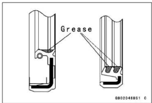
Donotremovepressedoilorgreasesealsunlessremoval isnecessary.Replacewithnewoneswheneverremoved. Pressnewoilsealswithmanufactureandsizemarksfacing out.Makesurethesealisalignedproperlywheninstalling.
Applyspecifiedgreasetothelipofsealbeforeinstalling theseal.
Circlips, CotterPins
Replacecirclipsorcotterpinsthatwereremovedwithnew ones. Takecarenottoopentheclipexcessivelywheninstallingtopreventdeformation.

natural_image
Technical illustration of a mechanical assembly with hands and a small block labeled 'OIL' (no text or symbols on the diagram itself)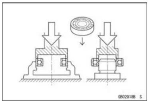
natural_image
Mechanical assembly diagram showing two mechanical components with downward force arrows, one bearing a circular component (no text or symbols)

natural_image
Technical illustration of a mechanical tool interacting with a workpiece, showing motion and assembly (no text or symbols)1-6GENERALINFORMATION
BeforeServicing
Lubrication
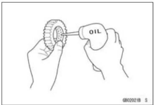
It is important to lubricator rotating or sliding parts during assembly to minimize weard during initial operation. Lubrication points are called out throughout this manual, apply the specific oilorgrease as specified.
DirectionofEngineRotation
Whenrotatingthecrankshaftbyhand, thefreeplay amountofrotatingdirectionwillaffecttheadjustment. Rotatethecrankshafttopositivedirection(clockwiseviewed fromoutputside).
ElectricalLeads
Atwo-colorleadisidentifiedfirstbytheprimarycolorand thenthestripecolor.Unlessinstructedotherwise,electrical leadsmustbeconnectedtothoseofthesamecolor.
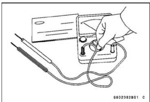
Instrument
Useameterthathasenoughaccuracyforanaccurate measurement.Readthemanufacture'sinstructionsthor- oughlybeforeusingthemeter.Incorrectvaluesmaylead toimproperadjustments.
natural_image
Line drawing of hands assembling a tire with a tool labeled 'OIL' (no text or symbols beyond label)
natural_image
Technical line drawing of a mechanical component with no visible text or symbols
natural_image
Line drawing of a hand using a multimeter to test electrical components (no text or symbols visible)ModelIdentification
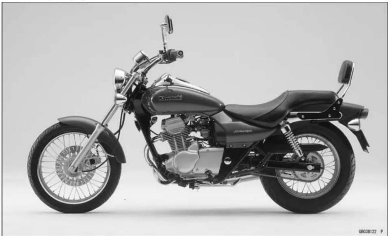
BN125-A1(Europe)LeftSideView
natural_image
Side profile of a black Kawasaki motorcycle with visible engine and wheel (no text or symbols)BN125-A1(Europe)RightSideView

natural_image
Side profile of a black Kawasaki motorcycle with visible engine and wheel (no text or symbols)1-8GENERALINFORMATION
ModelIdentification
BN125-A1(Singapore)LeftSideView

natural_image
Side profile of a black Kawasaki motorcycle with visible engine and wheel (no text or symbols)BN125-A1(Singapore)RightSideView

natural_image
Side profile of a black Kawasaki motorcycle with visible engine, power lines, and wheelbase (no text or symbols)GeneralSpecifications
| Items | BN125-A1 ~ A2 | BN125-A3 ~ A4 | BN125-A5 ~ |
| Dimensions | |||
| Overalllength2150mm(84.6in.) | |||
| Overallwidth780mm(30.7in.) | |||
| Overallheight1020mm(40.2in.) | 1035mm(40.8in.) | ←1050mm(41.3in.)(US,CA)1045mm(41.1in.)BN125-A7~ (N,NU) | |
| Wheelbase1470mm(57.9in.) | |||
| Roadclearance | 145mm(5.7in.)160mm(6.3in.) | ←155mm(6.1in.)(US,CA) | |
| Seatheight680mm(26.8in.) | |||
| Drymass | 128kg(1255N,282lb) | 135kg(1323N,298lb)132kg(1294N,291lb)(US):(BN125-A4~) | |
| Curbmass:Front64kg(628N,141lb)← | 66kg(647N,146lb)(CAL)65kg(637N,143lb)(BN125-A7~,N,NU) | ||
| Rear: | 80 kg (785 N, 176 lb) | 84 kg (824 N, 185 lb)81kg(794N,179lb):(BN125-A4, US,CA) | ←←82kg(804N,181lb)(CAL)83kg(814N,183lb)(BN125-A7~,N,NU) |
| Fueltankcapacity | 13L(3.43USgal) | ||
| Performance | |||
| Minimumturningradius | 2.5m(8.2ft.) | ||
| Engine | |||
| Type | 4-stroke,SOHC,1-cylinder | ||
| Coolingsystem | Air-cooled | ||
| Boreandstroke | 55×52.4mm(2.2×2.1in.) | ||
| Displacement | 124cm3(7.6cuin.) | ||
| Compressionratio | 9.6: 1 | ||
| Maximumhorsepower | 8.8kW(12PS)@9500r/min(rpm),(US)- | ←8.5kW(11.6PS)@9500r/min(rpm)(BN125-A7~,N,NU) | |
GeneralSpecifications
| Items | BN125-A1 ~ A2 | BN125-A3 ~ A4 | BN125-A5 ~ |
| Maximum torque 9.7N·m(0.99kgf·m,7.2ft·lb)@8000r/min(rpm)(US)- | ←9.8N·m(1.00kgf·m,7.2ft·lb)@8000r/min(rpm)(BN125-A7~,N,NU) | ||
| Carburetionsystem CarburetorStartingsystemIgnition systemTiming advanceIgnition timing From 10° BTDC | ,MIKUNIBS28Electric starterDC-CDIElectronically advanced (analog) | ||
| @1300r/min(rpm)to30° BTDC@4500r/min(rpm) | ←From 10° BTDC@1300r/min(rpm) to35° BTDC@4500r/min(rpm)(US,CA,CAL) | ||
| Spark plug NGKCR7E | ← | NGKCR7EorU22ESR-N:(BN125-A4~, US, CA) | |
| Valvetiming:Inlet:OpenCloseDurationExhaust:OpenCloseDurationLubricationsystemEngine oil:Grade | 23° BTDC57° ABDC260°64° BBDC16° ATDC260°Forcedlubrication(wetsump) | ||
| SE, SF or SG | ←(BN125-A3)APISE,SForSGAPISH,SJorSLwithJASOMA | ||
| ViscosityCapacity | SAE10W-40 | ||
| 1.4L(1.48USqt)(whenengine is completely dry) | |||
| Drive TrainPrimary reduction system:TypeReduction ratioClutch typeTransmission:Type | Gear3.666(77/21)Wetmultidisc5-speed,constantmesh,returnshift | ||
GeneralSpecifications
| Items | BN125-A1 ~ A2 | BN125-A3 ~ A4 | BN125-A5 ~ |
| Gear ratios: | |||
| 1st | 2.700(27/10) | ||
| 2nd | 1.705(29/17) | ||
| 3rd1.300(26/20) | |||
| 4th1.090(24/22) | |||
| 5th0.952(20/21) | |||
| Finaldrivesystem: | |||
| TypeChaindrive | |||
| Reduction ratio 3.066(46/15) | ← | 2.800(42/15)(BN125-A7~, N, NU) | |
| Overall drive ratio | 10.708 @Top gear | ←9.778@Topgear(BN125-A7~, N, NU) | |
| Frame | |||
| Type | Doublecradle | ||
| Caster(rake angle) | 34° | ||
| Trail | 121 mm(4.8in.) | ←119 mm (4.7 in.): BN125-A4 ~ (US, CA) | |
| RimSize: | |||
| Front | 17×1.85 | ||
| Rear | 15×2.75 | ||
| Fronttire: | |||
| TypeTubetype | |||
| Size | 90/90-17 M/C49P | ||
| Reartire: | |||
| TypeTubetype | |||
| Size | 130/90-15 M/C66P | ||
| Frontsuspension: | |||
| TypeTelescopic fork | |||
| Wheel travel | 130 mm (5.1 in.) | 140 mm (5.5 in.) | |
| Rearsuspension: | |||
| TypeSwingam | |||
| Wheel travel | 60 mm (2.4 in.) | 80 mm (3.1 in.) | |
| 75mm (3.0in.) | |||
| (BN125-A2~) | |||
| Braketype: | |||
| Front | Singledisc | ||
| Rear | Drum | ||
| Electrical Equipment | |||
| Battery | 12V9Ah | ||
| Headlight: | |||
| TypeSemi-sealed beam | |||
| Bulb | 12V60/55W | ||
1-12GENERALINFORMATION
GeneralSpecifications
| Items | BN125-A1 ~ A2 | BN125-A3 ~ A4 | BN125-A5 ~ |
| Trail/brakelight12V5/21WAlternator:TypeRatedoutput | Single-phaseAC8.75A/12V@4000r/min(rpm):BN125-A115A/14V@8000r/min(rpm):BN125-A2~ | ||
Specificationssubjecttochangewithoutnotice, and may not apply to every country.
(CA):CanadaModel
(US):UnitedStatesModel
(N): NoCatalyticConverter
(NU): No Catalytic Converter (United Kingdom Model)
TechnicalInformation-DC-CDI(DirectCurrent-CapacitorDischargeIgnitionSystem)
Description
○ UnliketheconventionalCDI, the DC-CDlusesabatteryinsteadofamagnetoasapowersource.
The DC-CDI powered by a battery generates strong ignitions parkeven at low engines speeds. The conventional CDI, which uses AC voltages supplied by an exciter coil, generates less ignitions spark at low engines speeds.
The DC-CDI has been built-in DC-DC converter which changes battery voltage or battery-changing voltage into high voltage AC. Even if the battery loses its charge, the DC-CDI can use battery-charging voltage.
TheDC-CDI doesn't have an exciter coil, a power consumer, therefore the battery is charged better.
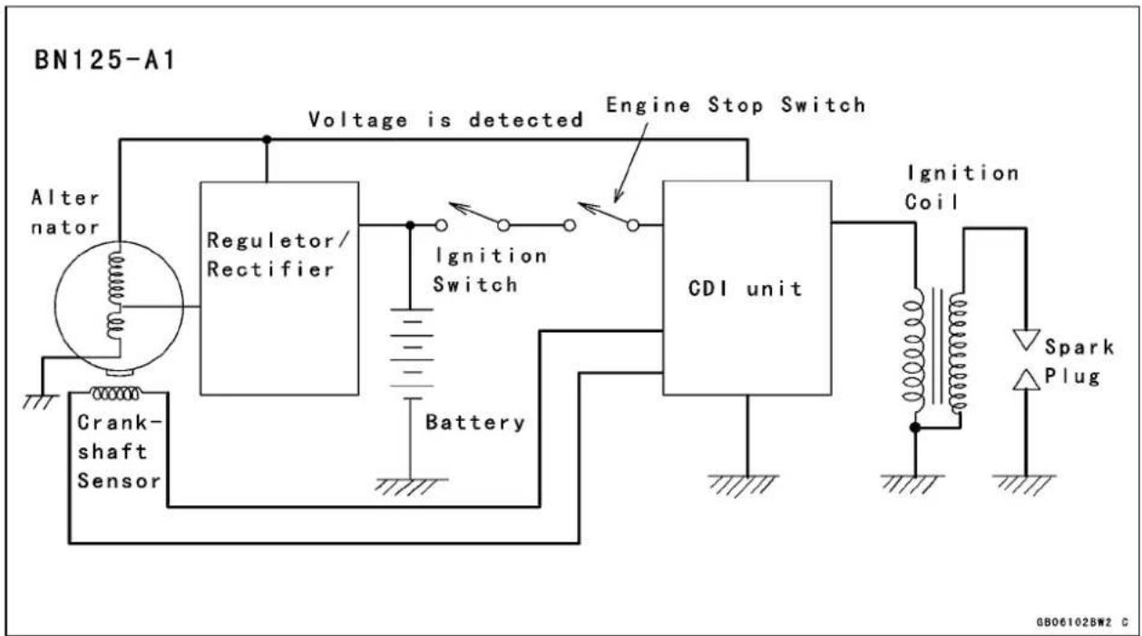
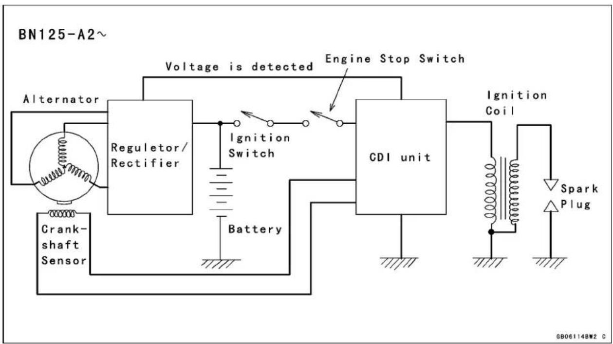
IgnitionSystem
TheDC-CDisconnectedasshown.
flowchart
graph TD
    A["Alternator"] --> B["Regulator/Rectifier"]
    B --> C["Ignition Switch"]
    C --> D["CDI unit"]
    D --> E["Ignition Coil"]
    E --> F["Spark Plug"]
    F --> G["Battery"]
    G --> H["Crank-shaft Sensor"]
    H --> B
    B --> I["Voltage is detected"]
    I --> J["Engine Stop Switch"]
    J --> D
flowchart
graph TD
    A["Alternator"] --> B["Regulator/Rectifier"]
    B --> C["Ignition Switch"]
    C --> D["CDI unit"]
    D --> E["Ignition Coil"]
    E --> F["Spark Plug"]
    F --> G["Battery"]
    G --> H["Crank-shaft Sensor"]
    B --> I["Voltage is detected"]
    D --> J["Engine Stop Switch"]
1-14GENERALINFORMATION
TechnicalInformation-DC-CDI(DirectCurrent-CapacitorDischargeIgnitionSystem)
Operation
TheDC-CDIcircuitconsistsofabattery,aDC-DCconverter,adiode,acapacitor,anignitiontiming controller, a crankshaft sensor, a thyristor, an ignition coil, a spark plug, an ignition switch, and an enginestopswitch.IftheignitionswitchortheenginestopswitchisturnedtotheOFFposition,the batterypowersupplyiscutoff,andnosparkisgenerated.
TheDC-DCconverterintheCDlunithasabuilt-intransformer,whichchanges12Vbatteryvoltageorbattery-chargingvoltageintoACvoltage.ThediodeconvertstheACvoltageintoabout225VDCtochargethecapacitor.
Firststep-ChargingtheCapacitor
Theconvertergeneratesthecurrenttochargethecapacitorthroughthediodewith225VDC.During thisprocess,thecurrentchangesslowlythroughtheprimarycoilwindingsothatthesecondarycoil windinggoesnotproduceenoughvoltagetofirethesparkplug.

flowchart
graph TD
    A["Battery"] --> B["Transformer"]
    B --> C["12V DC"]
    C --> D["225V DC"]
    D --> E["Capacitor (+)"]
    E --> F["Ignition Coil (-)"]
    F --> G["Charging"]
    G --> H["Crankshaft Sensor"]
    H --> I["Ignition Timing Controller"]
    I --> J["Thyristor"]
    J --> K["A"]
    K --> L["K"]
    L --> M["G"]
    M --> N["Spark Plug"]
    style A fill:#f9f,stroke:#333
    style B fill:#ccf,stroke:#333
    style C fill:#cfc,stroke:#333
    style D fill:#fcc,stroke:#333
    style E fill:#cff,stroke:#333
    style F fill:#ffc,stroke:#333
    style G fill:#cfc,stroke:#333
    style H fill:#fcc,stroke:#333
    style I fill:#cfc,stroke:#333
    style J fill:#fcc,stroke:#333
    style K fill:#cfc,stroke:#333
    style L fill:#fcc,stroke:#333
    style M fill:#cfc,stroke:#333
    style N fill:#fcc,stroke:#333
Secondstep-thyristorconducts
Aftercharging, the crankshaft sensor and ignition timing controllers send at triggers signal to the gate through the cathode (K → G in the figure) in the thyristor. When this happens, the current flows from the cathodeto the anode (K → A) in the thyristor.
Thirdstep-SurgingcurrentintothePrimaryWinding
Whenthethyristorconducts, the chargestored in the capacitor is released suddenly, flowing through the primary winding, backthrough the ethyristortothecapacitor.
TechnicalInformation-DC-CDI(DirectCurrent-CapacitorDischargeIgnitionSystem)

flowchart
graph TD
    Battery --> DC-DC_Converter["DC-DC Converter"]
    DC-DC_Converter --> Transformer["Transformer 12V DC → 225V DC"]
    Transformer --> Oscillator["Oscillator"]
    Oscillator --> Thyristor["Thyristor"]
    Thyristor --> IgnitionTiming["Ignition Timing Controller"]
    IgnitionTiming --> Crankshaft["Crankshaft Sensor"]
    Crankshaft --> PrimaryWinding["Primary Winding"]
    PrimaryWinding --> Discharging["Discharging"]
    Discharging --> Capacitor["Capacitor (+) (-)"]
    Capacitor --> IgnitionCoil["Ignition Coil"]
    IgnitionCoil --> SparkPlug["Spark Plug"]
    SparkPlug --> SecondaryWinding["Secondary Winding"]
    SecondaryWinding --> Drone["Drone"]
    Drone --> PrimaryWinding
    PrimaryWinding --> G["G"]
    G --> K["K"]
    K --> A["A"]
    A --> G
    style DC-DC_Converter fill:#f9f,stroke:#333
    style Battery fill:#fff,stroke:#333
    style Crankshaft fill:#fff,stroke:#333
    style PrimaryWinding fill:#fff,stroke:#333
    style SecondaryWinding fill:#fff,stroke:#333
    style SparkPlug fill:#fff,stroke:#333
    style Drone fill:#fff,stroke:#333
    style SecondaryWinding fill:#fff,stroke:#333
    style G fill:#fff,stroke:#333
    style K fill:#fff,stroke:#333
    style A fill:#fff,stroke:#333
    style K fill:#fff,stroke:#333
    style G fill:#fff,stroke:#333
    style K fill:#fff,stroke:#333
    style A fill:#fff,stroke:#333
    style K fill:#fff,stroke:#333
    style K fill:#fff,stroke:#333
    style K fill:#fff,stroke:#333
    style K fill:#fff,stroke:#333
    style K fill:#fff,stroke:#333
    style K fill:#fff,stroke:#333
    style K fill:#fff,stroke:#333
    style K fill:#fff,stroke:#334
This sudden change in the primary current induces a primary voltage (counterelectromotive force) which is equal to the capacitor voltage (about 225V) but against the discharging current. The primary voltage induces a high secondary voltage in the secondary coil, generating spark plug gap. The secondary voltage multiplied by winding ratio (about 90:1) reaches about 20000V.
Finalstep-Thyristorresets
After the charge stored in the capacitor is completely released, the cathodeoanode voltage is removed in the thyroid or and the thyroid receptor stops conducting and automatically resets. Then, the DC-DC converter charges the capacitor again and operation return to first step.
The control of Ignition Timing
Sincetheignitiontimingiselectronicallyadvancedorretarded, thissystemhasnomechanicalpartssuchasacam orcontactbreakersandtherearenopartstowearoutand noperiodicmaintenanceisrequired. So, thereisneverany needtoadjustthetimingonceithasbeeninstalledcorrectly.
Generally, the spark plug must be fired at a proper crank angle before top dead center (BTDC).
Atlowandmid-rangeenginespeeds, thefastertheengine runs, thefurthertheignitionTimingadvances. This preventsknocking and preignition, and providesbetterengine performance.
Iftheenginespeedincreasesfurther,notimingadvance isrequiredbecausetheenginecanbreatheinandburnthe fuel/airmixtureinashortertime.Theignitiontimingdoes notincreasefurtherandthetimingadvancestops.This alsoprovidesbetterengineperformanceandpreventsthe enginefromoverrunningandoverheating.
Theoperationofadiodeandthyristorisexplainedhere inordertodescribehowtheignitiontimingiscontrolled.

line
| Time (deg) | Ignition Timing (deg. BTDC) | |---|---| | low-middle speed | idling | | high speed | |1-16GENERALINFORMATION
TechnicalInformation-DC-CDI(DirectCurrent-CapacitorDischargeIgnitionSystem)
Diode
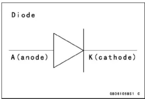
Adiodefunctionsasanelectricalcheckvalve.Itconducts currenteasilyfromitscathodetoitsanode,butitwillnot permitcurrentflowintheoppositedirection.Sinceelectricityattemptstoflowfromnegative(−)topositive(+),acircuitwithadonewillconductcurrentonlywhenthepolarity iscorrect,i.e.,whenthenegativechargeisappliedtothe diode'scathode.
NOTE
○ Thismanual doesn't usethe conventional current flow concept, but the electron theory current flow concept; currentissupposed to flownegative(−)topositive(+) in this text.
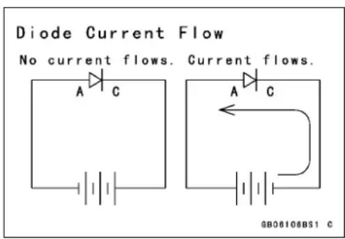
Thyristor(SCR)
Currentwillflowfromthecathodetoanodebutwillnot flowinthereversedirection. Thethyristordiffersfroma diodeintworespects:(a)eventhoughavoltageofthecorrectpolarity-negativetocathode-maybeapplied,thethyristorwillnotconductuntilasignalisappliedtothegateinput lead;(b)oncestarted,itwillnotstopconducting(evenifthe gateleadsignalvoltagestops)untilthecathodetoanode voltageisremovedorreversed.

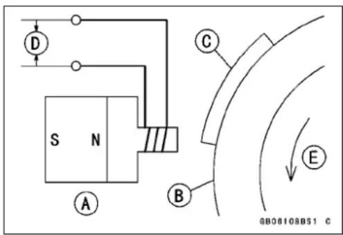
Thecrankshaftsensorisinstalledonthealternatorcover sothatitwillbeclosetothealternatorrotor. Onesideof thecrankshaftsensorcorehasapermanentmagnetand theothersidehasacoiltosignaltheCDlunit.
CrankshaftSensor[A]
AlternatorRotor[B]
TimingPlate[C]
OutputVoltage[D]
TechnicalInformation-DC-CDI(DirectCurrent-CapacitorDischargeIgnitionSystem)
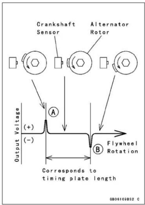
Everytimeeitherendofthetimingplateontherotor passesbythecrankshaftsensor,apulseisgeneratedand senttotheCDIunit,thatis,twopulsesaregeneratedper onerevolutionoftherotor.Oneisapositivepulse[A]and theotherisanegativepulse[B].
Thecrankshaftsensor,asignalgenerator,andvoltagecomparatorsdeterminetheignitiontimingintheignitiontimingcontroller.Thepowersupplycircuitisthepowersourceforthesignalgeneratorandthevoltagecomparators.

flowchart
graph LR
    A["Crankshaft Sensor"] --> B["Signal Generator"]
    B --> C["A Signal"]
    B --> D["B Signal"]
    C --> E["Comparator"]
    D --> E
    E --> F["Power Supply Circuit"]
    F --> G["Thyristor"]
    G --> H["K"]
    I["G"] --> G
1-18GENERALINFORMATION
TechnicalInformation-DC-CDI(DirectCurrent-CapacitorDischargeIgnitionSystem)
Thecrankshaftsensorgeneratesacrankshaftsensorsignalandsendsittothesignalgenerator. ThesignalgeneratorgeneratesAandBsignalssynchronizedwiththecrankshaftsensorsignal.Thesesignalsareshowninthefigure.
Thatistosay, the signal generator changesthe crank-shaftsensorsignal into A and B signals.

TechnicalInformation-DC-CDI(DirectCurrent-CapacitorDischargeIgnitionSystem)
(IgnitionTimingAdvancing)
AsignalandBsignalinthecomparatoradvancetheignitiontiming.
ThesignalgeneratordecreasesAsignalastheengine rpmincreasesfromN1,toN3asshown,butkeepsBsignal unchanged.
AandBsignalsareshownwiththesignalsoverlapped.
The comparator compares Asignal with Bsignal. When Asignal voltage becomes equal to or less than Bsignal voltage, the comparators sends atriggersignal to the gate in the thyristor, firing the spark plug.
The intersection point between A and B signals indicates the timing when the spark plug fires. This point moves left (the timing advances) asthe enginerp min increases from N1 to N3 as shown.

Beforeorafteradvancingperiod,theignitiontimingisdeterminedbythecrankshaftssensorsignalandtheignition timingremainsconstant.
The figureshowstheadvancingchart.

line
| Engine Speed | Ignition Timing (deg.BTDC) | | :--- | :--- | | Flat | Flat | | Advance | Advance | | Flat | Flat |1-20GENERALINFORMATION
TechnicalInformation-CoastingEnricher
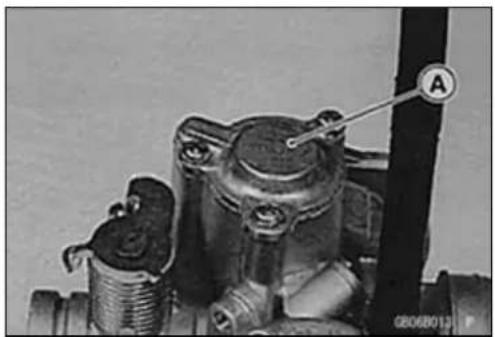
Thecoastingenricher[A]preventsbackfiringduringenginebrakingbysupplyingarichfuelmixturetotheengine.
natural_image
Close-up of a mechanical component with threaded end and labeled point A (no readable text or symbols)Whenthemotorcycleiscruisingoraccelerating,theenginevacuumislow,andthereturnspring[3] pushesthevalveinitsopenedposition[5].Thepassage[6]isopenandtheairrunsthroughthepilot jet[7]forbetteratomization.
Duringenginebraking,ahhighvacuumisgeneratedbehindthebutterflyvalve[11]. Thisdrawsthe diaphragm[2]againstthereturnspring[3]toclosethevalve[12],andthenthepassage[6]. The mixturebecomesrichtopreventbackfiringbecausetheamountofairisreduced.

GB060153W3 C
- PilotAirJet1
2.Diaphragm
- ReturnSpring
4.Cover
- ValveOpened
6.Passage
7.PilotJet
8.PilotAirJet2
9.PilotScrew
10.AirCleanerHousing
- ButterflyValve(ThrottleValve)
12ValveClosed
TechnicalInformation-CoastingEnricher
FuelandAirSupplyofEnricherSystem

flowchart
graph TD
    A["Fuel Tank"] --> B["Float Bowl"]
    B --> C["Main Jet"]
    D["Air Cleaner"] --> E["Carburetor Bore"]
    E --> F["Engine"]
    G["Pilot Air Jet1"] --> H["Pilot Jet"]
    I["Pilot Air Jet2"] --> H
    J["Bypass Outlet"] --> H
    K["Pilot Screw"] --> H
    L["Slow Passage"] --> H
    H --> M["Fuel"]
    H --> N["Mixture"]
    H --> O["Air"]
1-22GENERALINFORMATION
UnitConversionTable
PrefixesforUnits
| PrefixSymbolPower | |
| megaM×1000000kilok×1000centic× 0 . 0 1millim×0.001microp×0.000001 |
UnitsofMass
| kg | × | 2.205 | = | lb |
| g | × | 0.03527 | = | oz |
UnitsofVolume
| L | × | 0.2642 | = | gal(US) |
| L | × | 0.2200 | = | gal(imp) |
| L | × | 1.057 | = | qt(US) |
| L | × | 0.8799 | = | qt (imp) |
| L | × | 2.113 | = | pint (US) |
| L | × | 1.816 | = | pint (imp) |
| mL | × | 0.03381 | = | oz(US) |
| mL | × | 0.02816 | = | oz(imp) |
| mL | × | 0.06102 | = | cu in |
UnitsofForce
| N | × | 0.1020 | = | kg |
| N | × | 0.2248 | = | lb |
| kg | × | 9.807 | = | N |
| kg | × | 2.205 | = | lb |
UnitsofLength
| km | × | 0.6214 = | mile |
| m× | 3.281 = ft | ||
| mm | × | 0.03937 = | in |
UnitsofTorque
| N·m | × | 0.1020 | = | kgf·m |
| N·m | × | 0.7376 | = | ft·lb |
| N·m | × | 8.851 | = | in·lb |
| kgf·m | × | 9.807 | = | N·m |
| kgf·m | × | 7.233 | = | ft·lb |
| kgf·m | × | 86.80 | = | in·lb |
UnitsofPressure
| kPa | × | 0.01020 | = | kgf/cm2 |
| kPa | × | 0.1450 | = | psi |
| kPa | × | 0.7501 | = | cm Hg |
| kgf/cm2 | × | 98.07 | = | kPa |
| kgf/cm2 | × | 14.22 | = | psi |
| cm Hg | × | 1.333 | = | kPa |
UnitsofSpeed
| km/h | × | 0.6214 | = | mph |
UnitsofPower
| kW× | 1.360 | = | PS | |
| kW× | 1.341 | = | HP | |
| PS | × | 0.7355 | = | kW |
| PS | × | 0.9863 | = | HP |
Units of Temperature

line
| Value | Label | |---|---| | -40 | -20 | | -20 | -17.8 | | -4 | 0 | | 32 | 4.4 | | 68 | 26.7 | | 80 | 48.9 | | 104 | 60 | | 120 | 71.1 | | 140 | 80 | | 160 | 93.3 | | 176 | 100 | | 180 | 116 | | 200 | 120 | | 212 | 138 | | 248 | 140 | | 260 | 160 | | 284 | 160 | | 5 (°F + 40) / 5 | -40 = °F | | 5 (°F + 40) / 9 | -40 = °C |PeriodicMaintenance
TableofContents
PeriodicMaintenanceChart....2-2
TorqueandLockingAgent......2-4
Specifications....2-9
SpecialTools....2-11
PeriodicMaintenanceProcedures.....2-12
FuelSystem....2-12
FuelHoseandConnection Inspection....2-12
ThrottleGripFreePlayInspection2-12
ThrottleGripFreePlay Adjustment.....2-13
IdleSpeedInspection......2-13
IdleSpeedAdjustment.....2-14
AirCleanerElementCleaning.....2-14
EvaporativeEmissionControl SystemInspection(CAL)......2-14
EngineTop....2-15
AirSuctionValveInspection......2-15
CylinderHeadBoltTightness Inspection....2-16
ValveClearanceInspection......2-16
ValveClearanceAdjustment.....2-17
Clutch....2-17
ClutchLeverFree Play Inspection2-17
ClutchLeverFreePlay Adjustment.....2-17
EngineLubricationSystem....2-18
EngineOilChange....2-18
OilFilterChange 2-19
OilScreenCleaning 2-20
Wheels/Tires....2-21
Spoke Tightness Inspection .....2-21
RimRunoutInspection......2-21
AirPressureInspection/Adjustment....2-22
TireWearInspection....2-23
FinalDrive....2-23
DriveChainSlackInspection......2-23
DriveChainSlackAdjustment.....2-24
DriveChainWear Inspection .....2-25
Drive ChainLubrication....2-26
Brakes....2-26
Brake PedalFree Play Inspection2-26
BrakeShoeLiningWear Inspection....2-27
Brake PadWearInspection.....2-27
BrakeHoseandConnection Inspection....2-27
Brake FluidLevelInspection......2-28
Brake FluidChange....2-28
Brake LineBleeding....2-29
Brake/Master CylinderCup and Dust SealReplacement....2-31
CaliperPiston/DustSeals Replacement....2-31
Brake LightSwitchInspection.....2-31
Brake CableReplacement......2-31
Suspension....2-32
Front ForkOilChange......2-32
Front ForkOilLeakInspection.....2-33
Rear Shock AbsorberOil Leak Inspection....2-33
Swingarm PivotLubrication......2-33
Steering....2-34
Steering Inspection....2-34
Steering Adjustment....2-34
SteeringStemBearing Lubrication....2-35
Electrical System 2-35
BatteryElectrolyteLevel Inspection....2-35
Spark PlugCleaning/Inspection...2-35
Spark PlugGapInspection......2-35
General Lubrication....2-36
Lubrication....2-36
Nut, Bolt, and Fastener Tightness Inspection....2-37
Tightness Inspection....2-37
PeriodicMaintenanceChart
Thescheduledmaintenancemustbedoneinaccordancewiththischarttokeepthemotorcyclein good running condition. The initial maintenance is vitally important and must not be neglected.
| FREQUENCY | * O D O M E T E READING ×1000km (×1000mile) | |||||||
| Whichever comesfirst → | ||||||||
| ↓ Every | 161 (0.6) | 2182 (4) | 4303 (7.5) | 6 (12) | (15) | (20) | (24) | |
| Fuelhose,connections-inspect† | ● | ● | ● | ● | ● | ● | ||
| Throttlegripplay-inspect† | ● | ● | ● | ● | ||||
| Idlespeed-inspect | ● | ● | ● | ● | ||||
| Aircleanerelement-clean†# | ● | ● | ● | |||||
| Evaporativeemissioncontrolsystem (CAL)-inspect† | ● | ● | ● | ● | ● | ● | ● | |
| Airsuctionvalve-inspect(ATCH,DE,SI,US) | ● | ● | ● | ● | ● | ● | ||
| Cylinderheadbolttightness-inspect† | ● | ● | ● | ● | ||||
| Valveclearance-inspect† | ● | ● | ● | |||||
| Clutch-adjust | ● | ● | ● | ● | ● | ● | ● | |
| Engineoil-change# | 6month | ● | ● | ● | ● | ● | ● | ● |
| Oilfilter-replace | ● | ● | ● | ● | ||||
| Oilscreen-clean | ● | ● | ● | ● | ||||
| Spoketightnessandrimrunout-inspect† | ● | ● | ● | ● | ● | ● | ● | |
| Tirewear-inspect† | ● | ● | ● | ● | ● | ● | ||
| Drivechainslack-inspect†# | 1000km | |||||||
| Drivechainwear-inspect†# | ● | ● | ● | ● | ● | ● | ||
| Drivechain-lubricate# | 600km | |||||||
| Brakepedalfreeplay-inspect† | ● | ● | ● | ● | ● | ● | ● | |
| Brakeliningorpadwear-inspect†# | ● | ● | ● | ● | ● | ● | ||
| Brakehose,connections-inspect† | ● | ● | ● | ● | ● | ● | ||
| Brakefluidlevel-inspect† | month | ● | ● | ● | ● | ● | ● | ● |
| Brakefluid-change | 2years | ● | ||||||
| Brakemastercylindercupanddust cover-replace | 4years | |||||||
| Caliperfluidsealanddustseal-replace | 4years | |||||||
| Brakelightswitch-inspect† | ● | ● | ● | ● | ● | ● | ● | |
| Brakecable-replace | 2years | ● | ||||||
| Frontforkoil-change | 2years | ● | ||||||
| Frontforkoilleak-inspect† | ● | ● | ● | |||||
| Rearshockabsorberoilleak-inspect† | ● | ● | ● | |||||
| Swingarmpivot-lubricate | ● | ● | ● | |||||
| Steering-inspect† | ● | ● | ● | ● | ● | ● | ● | |
| Steeringstembearing-lubricate | 2years | ● | ||||||
| Batteryelectrolytelevel-inspect† | 6months | ● | ● | ● | ● | ● | ● | |
PeriodicMaintenanceChart
| FREQUENCY | * O D O M E T E R READING ×1000km (×1000mile) | |||||||
| Whichever comesfirst → | ||||||||
| ↓ Every | 161(0.6) | 2182(4) | 43036(7.5) | (12) | (15) | (20) | (24) | |
| Sparkplug-cleanandgap† | ● | ● | ● | ● | ● | ● | ||
| Generallubrication-perform | ● | ● | ● | |||||
| Nuts,bolts,andfastenerstightness-inspect | ● | ● | ● | ● | ||||
: Service more frequently when operating in severe conditions; dusty, wet, muddy, high speed, or frequent starting/stopping.
*: For higher odometer readings, repeat at the frequency interval established here.
†: Replace, add, adjust, clean, ortorque if necessary.
AT: Austria
CAL: California
CH: Switzerland
DE: Germany
SG: Singapore
US: United States
TorqueandLockingAgent
The following tables list the tightening torque for them major fasteners requiring use of a non-permanent locking agentor liquid gasket.
Lettersusedinthe"Remarks"columnmean:
L: Applyanon-permanentlockingagenttothethreads.
M:Applymolybdenumdisulfidegrease.
O: Applyanoiltothethreadsandseatingsurface.
S: Tightenthefasteners following the specified sequence.
| Fastener | Torque | Remarks | ||
| N·mkgf | mft·lb | |||
| FuelSystem | ||||
| UpperChamberCoverScrews3.50.3631in·lb | ||||
| SpringSeatScrews | 0.80.08 | 07 in · lb | ||
| ChokeLeverSetScrew | 0.8 | 0.080 | 7 in·lb | L |
| ChokeLeverPivotScrew | 2.00.20 | 17in·lb | ||
| PilotAirJet | 1.80.1815 | in·lb | ||
| Coasting Enricher Cover Screws | 2.0 | 0.20 | 17 in·lb | |
| PilotJet | 0.80.0807 | in · lb | ||
| MainJet | 1.80.1815 | in·lb | ||
| FloatValveHolderScrew | 2.00.20 | 17in·lb | ||
| ChokePlungerCap | 3.90.40 | 35in·lb | ||
| FloatBowlScrews | 2.00.20 | 17in·lb | ||
| CarburetorDrainPlug | 2.00.20 | 17in·lb | ||
| FuelTapPlateScr ews | 0.80.08 | 07 in · lb | ||
| Fuel Tap Diaphragm Cover Screws | 1.0 | 0.10 | 9 in·lb | |
| FuelTapMountingBolts(WhiteWasher) | 2.50.2522 | in·lb | ||
| FuelTapMountingBolts(BlackWasher) | 4.90.5043 | in·lb | ||
| EngineTopEnd | ||||
| ValveAdjustingCapBolts(Bn125-A1~ A3) | 9.8 | 1.0 | 87in·lb | |
| ValveAdjusting gCapBolts(BN125-A4~) | 8.80.90 | 78in·lb | ||
| Camshaft Chain Cover Bolts (BN125-A1 ~ A3) | 9.8 | 1.0 | 87 in·lb | |
| Camshaft Chain Cover Bolts (BN125-A4 ~) | 8.8 | 0.90 | 78 in·lb | |
| Cylinder Head Bolts M9 | 26 | 2.7 | 19 | O, M, S(washer) |
| CylinderHeadBoltsM6 | 12 | 1.2104in·lb | S | |
| CamshaftChainCoverDamperBolts(BN125-A1~ A3) | 9.8 | 1.0 | 87in·lb | |
| CamshaftChainCoverDamperBolts(BN125-A4~) | 8.80.90 | 78in·lb | ||
| Sparkplug | 13 | 1.3 | 9.5 | |
| Cylinder Head Blank Cap Bolt (BN125-A1 ~ A3) | 9.8 | 1.0 | 87in·lb | |
| CylinderHeadBlankCapBolt(BN125-A4~) | 8.80.90 | 78in·lb | ||
| CarburetorHolderBolts | 9.8 | 1.0 | 87in·lb | |
| Air Suction Valve Cover Bolts (BN125-A1 ~ A3) | 9.8 | 1.0 | 87in·lb | |
| AirSucti onValveCoverBolts(BN125-A4~) | 8.80.90 | 78in·lb | ||
| CylinderHeadPlug | 4.90.5043 | in·lb | ||
| VacuumHoseFitting | 5.90.6052 | in·lb | ||
TorqueandLockingAgent
| Fastener | Torque | Remarks | ||
| N·mkgf· | mft·lb | |||
| OilPipeBanjoBoltsM89.81.087in·lb | ||||
| OilPipeBanjoBoltsM10252.518 | ||||
| Oil Pipe Mounting Bolts (BN125-A1 ~ A3) | 9.8 | 1.0 | 87 in·lb | |
| OilPipeMountingBolts(BN125-A4~) | 8.80.90 | 78in·lb | ||
| CamshaftBearingHolderBolts(BN125-A1~A3) | 9.81.08 | 7in·lb | ||
| Camshaft Bearing Holder Bolts (BN125-A4 ~) | 8.8 | 0.90 | 78 in·lb | |
| Camshaft Sprocket Bolts | 12 | 1.2 | 104 in·lb | |
| Camshaft Chain Holder Screw | 4.9 | 0.50 | 43 in·lb | |
| Camshaft Chain Guide Bolts | 8.8 | 0.90 | 78 in·lb | |
| ChainTensionerMountingBolts(BN125-A1~A3) | 9.81.08 | 7in·lb | ||
| Chain Tensioner Mounting Bolts (BN125-A4 ~) | 8.80.90 | 78in·lb | ||
| ChainTensionerCap | 4.90.50 | 43in·lb | ||
| ValveAdjustingScrewLocknuts | 151.5 | 11 | ||
| Rocker Shaft Bolts | 8.8 | 0.90 | 78 in·lb | |
| Muffler Mounting Nut | 15 | 1.5 | 11 | |
| Clutch | ||||
| Clutch Hub Bolt | 98 | 10.0 | 72 | |
| ClutchSpringBolts | 8.80.907 | 8in·lb | ||
| Clutch Cover Bolts (BN125-A1 ~ A3) | 9.8 | 1.0 | 87 in·lb | |
| ClutchCoverBolts(BN125-A4~) | 8.80.90 | 78in·lb | ||
| Oil Seal Retaining Plate Bolts (BN125-A1 ~ A3) | 9.81.08 | 7in·lb | ||
| Oil Seal Retaining Plate Bolts (BN125-A4 ~) | 8.80.90 | 78in·lb | ||
| ClutchCoverDamperBolts | 8.80.90 | 78in·lb | L | |
| StarterLocknutSwitchScrews | 1.0 | 0.10 | 9 in·lb | |
| PrimaryGearNut | 697.051 | |||
| EngineLubricationSystem | ||||
| EngineOilDrainPlug | 181.813 | |||
| Oil Screen Cover Bolts (BN125-A1 ~ A3) | 9.8 | 1.0 | 87 in·lb | |
| Oil Screen Cover Bolts (BN125-A4 ~) | 8.8 | 0.90 | 78 in·lb | |
| Oil Pressure Relief Valve | 15 | 1.5 | 11 | |
| Oil Filter Cover Bolts (BN125-A1 ~ A3) | 9.8 | 1.0 | 87 in·lb | |
| OilFilterCoverBolts(BN125-A4~) | 8.80.90 | 78in·lb | ||
| OilPumpMountingScrews | 4.90.50 | 43in·lb | ||
| OilPumpAssyScrew | 9.81.08 | 7in·lb | ||
| OilPipeBanjoBolt | 252.518 | Clutch Cover,S Cylinder Head,S | ||
| Oil Pipe Banjo Bolts | 9.8 | 1.0 | 87 in·lb | |
| OilPipeMountingBolts(BN125-A1~ A3) | 9.81.08 | 7in·lb | ||
| OilPipeMountingBolts(BN125-A4~) | 8.80.90 | 78in·lb | ||
| OilFillerPlug | 2.50.25 | 22in·lb | ||
TorqueandLockingAgent
| Fastener | Torque | Remarks | ||
| N·m | kgf·mft·lb | |||
| EngineRemoval/installation | ||||
| EngineMountingBolts,Nuts(M10) | 444.533 | |||
| EngineMountingBolts,Nuts(M8) | 252.518 | |||
| EngineMountingBracketBolts,Nuts252.518 | ||||
| EngineGroundTerminalBolt | 9.81.087 | in·lb | ||
| Crankshaft/transmission | ||||
| PrimaryGearNut | 697.051 | |||
| BalancerShaftGearNut | 788.058 | O | ||
| CrankcaseBolts | 8.80.907 | in·lb | ||
| CrankcaseBearingR etainerScrews | 4.90.504 | in·lb | ||
| Neutral Switch | 15 | 1.5 | 11 | |
| ShiftDrumCamScrew | 4.90.5043 | in·lb | L | |
| Gear Set Lever Nut | 11 | 1.1 | 95 in·lb | |
| Engine Sprocket Holder Bolts | 12 | 1.2 | 104 in·lb | |
| Shift Return Spiring Pin (Bolt) | 29 | 3.0 | 21 | L |
| Shift Lever Clamp Bolt | 12 | 1.2 | 104 in·lb | |
| ShiftPedalNut | 303.122 | |||
| Wheels/tires | ||||
| FrontAxleNut | 788.058 | |||
| Rear Axle Nut | 98 | 10.0 | 72 | |
| Tire Air Valve Nuts | 1.5 | 0.15 | 13 in·lb | |
| Spoke Nipples | 2.0 ~ 3.9 | 0.20 ~ 0.40 | 17 ~ 35 in·lb | |
| FinalDrive | ||||
| Engine Sprocket Cover Bolts (BN125-A1 ~ A3) | 9.8 | 1.0 | 87 in·lb | |
| Engine Sprocket Cover Bolts (BN125-A4 ~) | 8.8 | 0.90 | 78 in·lb | |
| Engine Sprocket Cover Damper Bolts | 8.8 | 0.90 | 78 in·lb | L |
| TorqueLinkBoltandNut | 343.525 | |||
| RearSprocketN ut | 262.719 | |||
| Rear Axle Nut | 98 | 10.0 | 72 | |
| EngineSprocketHolderBolts | 121.210 | in·lb | ||
| Brakes | ||||
| BrakeDiscBolt | 272.820 | |||
| CaliperMountingBolts | 252.518 | |||
| CaliperHolder ShaftBolt | 181.813 | |||
| CaliperPadBolts | 181.813 | |||
| Caliper Bleed Valves | 7.8 | 0.80 | 69 in·lb | |
| BrakeHoseBanjoBolts | 252.518 | |||
| Brake Lever Pivot Bolt | 5.9 | 0.60 | 52 in·lb | |
| Brake Lever Pivot Bolt Locknut | 5.9 | 0.60 | 52 in·lb | |
| FrontBrakeRes ervoirCapScrews | 1.50.15 | 13in·lb | ||
| Front Brake Light Switch Screws | 1.0 | 0.10 | 9 in·lb | |
| Front Master Cylinder Clamp Bolts | 8.8 | 0.90 | 78 in·lb | S |
| TorqueLinkBoltandNut | 343.525 | |||
TorqueandLockingAgent
| Fastener | Torque | Remarks | ||
| N·mkgf | mft·lb | |||
| BrakePedalBolt9.81.087in·lb | ||||
| Suspension | ||||
| FrontForkTopPlugs232.317 | ||||
| FrontForkBottomAllenBolts202.015L | ||||
| FrontForkClampBolts(Upper) | 202.015 | |||
| FrontForkClampBolts(Lower) | 343.525 | |||
| RearShockAbsorberNuts(Upper) | 343.525 | |||
| RearShockAbsorberBolts(Lower) | 343.525 | |||
| Swingarm Pivot Nut | 98 | 10.0 | 72 | |
| Steering | ||||
| SteeringStemHeadBolt | 444.533 | |||
| SteeringStemNut | Hand-tight or4.9 | Hand-tight or0.50 | Hand-tight or43in·lb | |
| HandlebarNuts | 343.525 | |||
| Handlebar Holder Clamp Bolts (BN125-A3 ~) | 20 | 2.0 | 15 | S |
| Handlebar Weight Screws | - | - | - | L |
| Handlebar Switch Housing Screws | 3.4 | 0.35 | 30 in·lb | |
| FrontForkClampBolts(Upper) | 202.015 | |||
| FrontForkClampBolts(Lower) | 343.525 | |||
| Frame | ||||
| FrontFootpegBolts | 232.3 | 16.5 | ||
| ElectricalSystem | ||||
| SparkPlug | 13 | 1.3 | 113 in·lb | |
| CrankshaftSensorScrews | 3.9 | 0.40 | 35in·lb | |
| Ignition Coil Bolt | 6.9 | 0.70 | 61 in·lb | |
| Igniter Mounting Screws | 4.9 | 0.50 | 43 in·lb | |
| AlternatorCoverBolts | 8.8 | 0.9078in·lb | ||
| Alternator Cover Damper Bolts | 8.8 | 0.90 | 78 in·lb | L |
| Alternator Rotor Nut (BN125-A1 ~ A2) | 69 | 7.0 | 51 | |
| Alternator Rotor Nut (BN125-A3) | 98 | 10.0 | 72 | |
| AlternatorRotorNut(BN125-A4~) | 104 | 10.6 | 76 | |
| StarterCoilBolts | 13 | 1.3 | 113 in·lb | |
| Alternator Lead Holder Bolts (BN125-A1 ~ A2) | 13 | 1.3 | 113 in·lb | |
| AlternatorLeadHolderBolts(BN125-A3~) | 8.8 | 0.9078in·lb | ||
| StarterMotorTerminalLocknut | 6.9 | 0.7061in·lb | ||
| StarterMotorTerminalNut | 4.9 | 0.5043in·lb | ||
| Starter Relay Terminal Bolt | 4.9 | 0.50 | 43 in·lb | |
| Starter Motor Assembly Bolts | 3.4 | 0.35 | 30 in·lb | |
| Starter Motor Mounting Bolts | 8.8 | 0.90 | 78 in·lb | |
| Starter Motor Clutch Bolts (BN125-A1) | 34 | 3.5 | 25 | L |
| Starter Motor Clutch Bolts (BN125-A2 ~) | 12 | 1.2 | 104 in·lb | L |
| Headlight Body Screws | 2.9 | 0.30 | 26 in·lb | |
| HandlebarSwitchHousingScrews | 3.4 | 0.3530in·lb | ||
2-8 PERIODIC MAINTENANCE
TorqueandLockingAgent
| Fastener | Torque | Remarks | ||
| N·m | kgf·mft·lb | |||
| TurnSignalLightHolderNuts | 5.90.60 | 52in·lb | ||
| NeutralSwitch | 151.511 | |||
| SidestandSwitchScrews | 3.90.40 | 35in·lbL | ||
The table below, relating tightening torque to thread diameter, lists the basic torque for the bolts and nuts. Use histable for only the bolts and nuts which do not require a specific torque value. Allof the values are for use with dry solvent-cleaned threads.
BasicTo rqueforGeneralFasteners
| Threadsdia.(mm) | Torque | ||
| N·m | kgf·m | ft·lb | |
| 5 | 3.4 ~ 4.9 | 0.35 ~ 0.50 | 30 ~ 43 in·lb |
| 6 | 5.9 ~ 7.8 | 0.60 ~ 0.80 | 52 ~ 69 in·lb |
| 8 | 14 ~ 19 | 1.4 ~ 1.9 | 10.0 ~ 13.5 |
| 10 | 25 ~ 34 | 2.6 ~ 3.5 | 19.0 ~ 25 |
| 12 | 44 ~ 61 | 4.5 ~ 6.2 | 33 ~ 45 |
| 14 | 73 ~ 98 | 7.4 ~ 10.0 | 54 ~ 72 |
| 16 | 115 ~ 155 | 11.5 ~ 16.0 | 83 ~ 115 |
| 18 | 165 ~ 225 | 17.0 ~ 23.0 | 125 ~ 165 |
| 20 | 225 ~ 325 | 23 ~ 33 | 165 ~ 240 |
Specifications
| Item | StandardServiceLimit | |
| FuelSystemThrottle Grip Free PlayIdleSpeed1300±50r/min(rpm)AirCleanerElementOil:GradeSE,SForSGclass--ViscositySAE30-- | --- | |
| --- | ||
| EngineTopEndValveClearance:InletExhaust | 0.08~0.12(0.0031~0.0047in.)0.15~0.19(0.0059~0.0075in.) | --- |
| --- | ||
| ClutchClutch Lever Free Play | 2~3mm (0.08~0.12 in.) | --- |
| EngineLubricationSystemEngineOil:Grade:(BN125-A1~A3)APISE,SFor(BN125-A4~)ViscosityCapacity1.1L(1.16USqt)(whenfilterisnotremoved)Level | SGAPI SE, SF or SGAPISH,SJorSLwithJASOMASAE10W-40iterisnotremoved)1.2 L (1.27 US qt) (when filter is removed)1.4L(1.48USqt)(whenengineiscompletelydry)Betweenupperandlowerlevellines(Wait 2~3 minutes after idling orrunning) | --- |
| --- | ||
| --- | ||
| --- | ||
| --- | ||
| --- | ||
| --- | ||
| TiresRimRunout(WithTireInstalled):AxialRadialAirPressure(WhenCold):Front:(BN125-A1~A2)(BN125-A3~)Rear:(BN125-A1~A2)(BN125-A3~)TreadDepth:Front:(BN125-A1~A2)(BN125-A3~A5) | TIR 0.8 mm (0.03 in.) or lessTIR 1.0 mm (0.04 in.) or lessUp to 185 kg (408 lb) load: 150 kPa (1.5kgf/cm2,21psi)Up to 155 kg (342 lb) load: 150 kPa (1.5kgf/cm2,21psi)Up to 185 kg (408 lb) load: 175 kPa(1.75kgf/cm2,25psi)Up to 155 kg (342 lb) load: 175 kPa(1.75kgf/cm2,25psi)4.5 mm (0.18 in.)4.0 mm (0.157 in.) | TIR 2.0 mm (0.08 in.)TIR 2.0 mm (0.08 in.)--- |
| --- | ||
| --- | ||
| --- | ||
| --- | ||
| 1 mm (0.04 in.)1 mm (0.04 in.) |
Specifications
| ItemStandardServiceLimit | ||
| (BN125-A6 ~)Rear7.3mm(0.29in.)2mm(0.08in.) | 4.1 mm (0.161 in.) | 1 mm (0.04 in.) |
| FinalDriveDrive Chain Slack20LinkLength | 25 ~ 40 mm (0.98 ~ 1.57 in.)254.0~ 254.6mm(10.00 ~ 10.02in.) | - - -259mm(10.2in.) |
| BrakesBrakeLeverFreePlayNon-adjustable- - -Brake Pedal Free PlayShoe Lining ThicknessBrakeFluid:GradeBrakePadLiningThickness:(BN125-A1 ~ A2)(BN125-A3 ~)BrakeLightTiming:FrontRear | 20 ~ 30 mm (0.79 ~ 1.18 in.)3.85 ~ 4.15 mm (0.152 ~ 0.163 in.)DOT44.5 mm (0.177 in.)6.0 mm (0.236 in.)Pulled onOnafterabout10mm(0 .39in.)ofpedal travel | - - -2 mm (0.08 in.)- - -1 mm (0.04 in.)1 mm (0.04 in.)- - -- - - - - |
| SuspensionOil ViscosityOilCapacity(ParUnit):CompletelyDryWhenChangingOilOilLevel(FullyCompressed,WithoutMainSpring) | SHOWA SS-8 or equivalent191±2.5mL(6.46±0.085USoz.)Approx165mL(5.58USoz.)218±2mm(8.58±0.08in.) | - - -- - - -- - - - |
| ElectricalsystemSpark Plug GapBattery Electrolyte Level | 0.7 ~ 0.8 mm (0.028 ~ 0.031 in.)Between level lines | - - -- - - - |
SpecialTools
SteeringStemNutWrench: 57001-1100

natural_image
Line drawing of a mechanical wrench with a curved handle and two notches (no text or symbols)ForkOilLevelGauge: 57001-1290

natural_image
Technical line drawing of a mechanical assembly with spring-loaded components (no text or symbols)Jack:
57001-1238

natural_image
Technical line drawing of a mechanical support structure (no text or symbols)2-12 PERIODIC MAINTENANCE
PeriodicMaintenanceProcedures
FuelSystem
FuelHoseandConnectionInspection
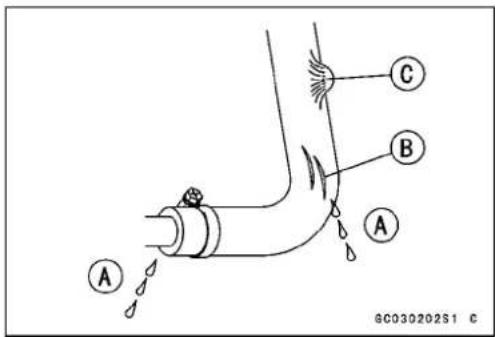
The fuelhose is designed to be used throughout the motorcycle's lifewithout anymaintenance, however, if the motorcycle is not properly handled, the inside the fuel line can cause fuel to leaks [A] or the host of a vehicle. Remove the fuel tank (see Fuel System chapter) and check the fuel hose.
★Replacethefuelhoseifanyfraying,cracks[B]orbulges [C]arennoticed.
- Check that the hose is securely connected and clamps are tightened correctly.
- Wheninstalling, routethehoseaccordingtoCable, Wire, and HoseRoutingsectionintheAppendixchapter.
- Wheninstallingthefuelhoseavoidssharpbending,kinking,flatteningortwisting,androutethefuelhosewitha minimumofbendingsothatthefuelflowwillnotbeobstructed.
★Replacethehoseifithasbeensharplybentorkinked.
ThrottleGripFreePlayInspection
Ifthethrottlegriphasexcessivefreeplayduetocable stretchormisadjustment,therewillbeadelayinthrottleresponse.Also,thethrottlevalvemaynotopenfullyatfull throttle.Ontheotherhand,ifthethrottlegriphasnoplay, thethrottlewillbehardtocontrol,andtheidlespeedwill beerratic.CheckthethrottlegripplayperiodicallyinaccordancewiththePeriodicMaintenanceChart,andadjustthe playifnecessary.
ThethrottlecableroutingisshowninCable, Harness, HoseRoutingsectionintheAppendixchapter.
- Checkthethrottlegripfreeplay[A].
★Ifthefreeplayisincorrect,adjustthethrottlecable.
ThrottleGripFreePlay
Standard: 2 \~ 3 mm (0.08 \~ 0.12 in.)
- Check that the throttle grip movess smoothly from full open to close, anth throttle closes quickly and completely in all steering positions by thereturn spring.
★ Ifthethrottlegripdoesnotreturnproperly, checkthethrottlecablerouting, gripfreeplay, andcabledamage. Then lubricatethethrottlecable. - Runtheengineattheidlespeed, andturnthehandlebar allthewaytotherightandlefttoensurethattheidlespeed doesnotchange.
★ If the idlespeed increase, check the throttlegrip free play and the cablerouting.

natural_image
Mechanical component with labeled section A, showing shaft and housing assembly (no readable text or symbols)PeriodicMaintenanceProcedures
ThrottleGripFreePlayAdjustment
- Loosenthelocknut[A].
- Turntheadjuster[B]untiltheproperamountoffreeplay canbeobtained.
-
Tightenthelocknutagainsttheadjuster.
★ Ifthethrottlegripfreeplaycannotbeadjustedwiththe adjuster, usethecableadjustersatthelowerendsofthe throttlecables. -
Loosenthelocknut, andscrewtheadjusterattheupper endoftheacceleratorcableallthewayin.
- Tightenthelocknutsecurelyagainsttheadjuster.
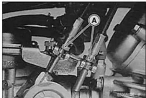
- Adjustereitherlowernuts[A]oftheacceleratorcableor the deceleratorcableuntilthecorrectthrottlegripfreeplay isobtained.
★ Ifthefreeplaycannotbeadjustedwiththeloweradjusting nuts, usetheadjusterattheupperendofthecableagain.
- Check that the throttle pulley [B] stops [C] against the idle adjustingscrew [A] with the throttle grip closed.

natural_image
Mechanical assembly diagram showing components like gears and springs (no visible text or labels)
IdleSpeedInspection
- Starttheengineandwarmitupthoroughly.
- Withtheengineidling,turnthehandlebartobothsides.
★ Ifhandlebarmovementchangestheidlespeed,thethrot-tlecablemaybeimproperlyadjustedorincorrectlyrouted,ordamaged.Besuretocorrectanyoftheseconditions beforeriding(seeCable,Wire,andHoseRoutingsection inAppendixchapter).
WARNING
Operationwithanimproperlyadjusted,incorrectly routed,ordamagedcablecouldresultinanunsafe ridingcondition.
- Checkidlespeed.
★ If the idlespeedis out of the specified range, adjust it.
IdleSpeed
Standard:1300±50r/min(rpm)
2-14 PERIODIC MAINTENANCE
PeriodicMaintenanceProcedures
IdleSpeedAdjustment
- Starttheengineandwarmitupthoroughly.
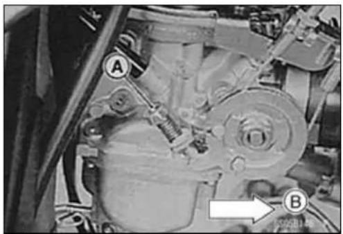
- Turntheidleadjustingscrew[A]untiltheidlespeedis correct.
Openandclosethethrottleafewtimestomakesurethat theidlespeediswithinthespecifiedrange.Readjustif necessary.
Front[B]
AirCleanerElementCleaning
NOTE
○ Industryareas, theelementshouldbecleanedmore frequentlythantherecommendedinterval.
○ Afterridingthroughrainoronmuddyroads, theelement should be cleaned immediately.
○ Sincerepeatedcleaningopenstheporesofthefoam element,replaceitwithanewoneinaccordancewith thePeriodicMaintenanceChart. Also,ifthereisabreak intheelementmaterialoranyotherdamagetotheelement,replacetheelementwithanewone.
WARNING
Cleantheelementinawell-ventilatedarea,and makesurethatthereisnosparkorflameanywhere neartheworkingarea. Becauseofthedangerof highlyflammableliquids,donotusegasolineora low-flashpointsolventtocleantheelement.
- Removetheaircleanerelement(seeFuelSystemchapter).
- Cleantheelementinabathofhigh-flash-pointsolvent, andthendryitwithcompressedairorbyshakingit.
- Visuallychecktheelementfortearsorbreaksandreplace thedamagedelementwithanewone.
- Aftercleaning, saturatetheelementwithSE,SF,orSG classSAE30oil,squeezeoutexcessoil.
- Wraptheelement[A]inacleanrag[B]andsqueezeitas dryaspossible.
EvaporativeEmissionControlSystemInspection (CAL)
CanisterInspection
- Removethecanistercover[A].
natural_image
Mechanical assembly diagram showing components labeled A and B with no readable text or symbols

natural_image
Close-up of a car's front bumper with labeled component A, mounted on a grille (no text or symbols beyond label)PeriodicMaintenanceProcedures
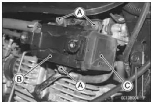
- Removethecanistermountingbracketbolts[A]andremovethebrackets[B]andcanister[C]together.
- Disconnectthehosesfromthecanister.
- Visually inspect the canister for cracks and other damage.
★ Ifthecanisterhasanycracksorbaddamage,replaceit withanewone.
NOTE
○Thecanisterisdesignedtoworkwellthroughthemotor cycle'slifewithoutanymaintenanceifitisusedunder normalconditions.
SeparatorInspection
- Removetherightsidecover(seeFramechapter).
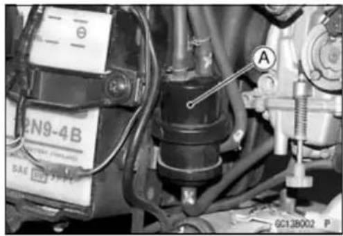
- Disconnect the hoses from the liquid/vapor separator [A], and remove these separator up from the bracket.
- Visually inspect these separator for cracks and other damage.
★ If these separator has any cracks or is badly damaged, replace it with anewone.
natural_image
Close-up of mechanical components with no visible text or symbolsEngineTop
AirSuctionValveInspection
- Removetheairsuctionvalve(seeEngineTopEndchapter).
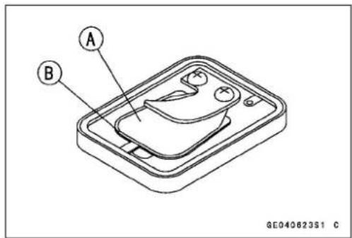
- Visually inspect thereeds[A]for cracks, folds, warps, heat damage, or other damage.
★ If thereisanydoubtastotheconditionofthereed, replace theairsuctionvalveasanassembly. - Checkthereedcontactareas[B]ofthevalveholderfor grooves,scratches,anysignsofseparationfromthe holder,orheatdamage.
★ If there is any doubt to the condition of thereed contact areas, replace the air suction valve as an assembly.
★ Ifanycarbonorotherforeignparticles have accumulated between thereed and thereed contact area, wash the valve assembly with a high-flash-points solvent.
CAUTION
Donotscrapeoffthedepositswithascpraperasthis coulddamagetherubber,requiringreplacementof thesuctionvalveassembly.
2-16 PERIODIC MAINTENANCE
PeriodicMaintenanceProcedures
CylinderHeadBoltTightnessInspection
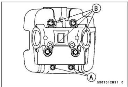
- Checkthat6mm[A]and9mm[B]cylinderheadboltsare tightenedevenly.
★Standardheadboltstighteningtorqueareshownbelow.
TighteningTorque
6mmCylinderHeadBolts:12N·m(1.2kgf·m,104in·lb)
9mmCylinderHeadBolts:26N·m(2.7kgf·m,19ft·lb)
ValveClearanceInspection
CAUTION
Ifvalveclearanceisleftunadjusted, wearwilleventuallycausethevalvestoremainpartyopen, which lowersperformance, burnsthevalvesandthevalve seats, and may causes seriousenginedamage.
NOTE
○ Valveclearancemustbecheckedandadjustedwhen theengineiscold(atroomtemperature).
- Remove:
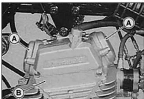
ValveAdjustingCaps[A]
CamshaftChainCover[B]
- Turnthecamshaftcenterbolt[A]counterclockwisewitha wrench.
○Makingsurethattheinletvalveopensandthencloses, starttoturntheboltinthesamedirectionuntilthe“T”mark [C]onthecamshaftsprocketalignswiththetimingmark [B]onthecylinderhead.ThisshowsthatthepistonTDC isattheendofthecompressionstroke.
- Usingathicknessgauge[A],measurethevalveclearance betweenheadjustingscrewandvalvestem.Measure theclearanceforbothvalvesatatime.
ValveClearance(whencold)
Standard:
Inlet
0.08 \~ 0.12 mm (0.0031 \~ 0.0047 in.)
Exhaust
0.15 \~ 0.19 mm (0.0059 \~ 0.0075 in.)
natural_image
Close-up of a mechanical assembly with labeled parts A and B (no readable text or symbols)

natural_image
Close-up of a mechanical assembly with labeled component A (no readable text or symbols)PeriodicMaintenanceProcedures
ValveClearanceAdjustment
★ Ifthevalveclearanceisnotwithinthespecifiedrange, adjusttheclearancebylooseningthelocknutandturning theadjustingscrew.
- Tightenthenutstothespecifiedtorqueandcheckthe valveclearanceagain.
Torque-ValveAdjustingScrewLocknut:15N·m(1.5 kgf·m,11ft·lb)
- Installthevalveadjustingcapswiththeir"up"marks[A] up.
Torque-ValveAdjustingCapBolts
(BN125-A1\~A3):9.8N·m(1.0kgf·m,87in·lb)
(BN125-A4 \~): 8.8 N·m (0.90 kgf·m, 78 in·lb)

Clutch
ClutchLeverFreePlayInspection
- Check that the clutch cable upper end is fully seated in the adjuster[A].
- Pulltheclutchlever[B]justenoughtotakeupthefree play[C].
○Measurethegap(freeplay)betweentheleverandthe leverholder.
★ Ifthegap(freeplay)istoowide, theclutchmaynotreleasefully. Ifthegapistoonarrow, theclutchmaynotengagefully. Ineithercase, adjustit.

ClutchLeverFreePlay
Standard: 2 \~ 3 mm (0.08 \~ 0.12 in.)
ClutchLeverFreePlayAdjustment
WARNING
To avoid as serious burn, nevertouch the engine or exhaust piped during clutch adjustment.
- Slidebackthedustcover.
- Loosenbothadjusternuts[A]attheclutchcablebracket asfarastheywillgo.
- Loosentheknurledlocknut[A]attheclutchlever.
- Turn the adjuster [B] so that 5 \~ 6 mm (0.20 \~ 0.24 in.) [C] of threads are visible.

natural_image
Close-up of an automotive engine component with visible springs, calipers, and a circular valve (no text or symbols)
2-18 PERIODIC MAINTENANCE
PeriodicMaintenanceProcedures
- Pulltheclutchcable[A]tightandtightentheadjustingnuts [B]againsttheclutchcablebracket.
- Turntheadjusterattheclutchleveruntilthefreeplayis correct.
- Tightentheknurledlocknutattheclutchlever.
WARNING
Besurethattheoutercableendattheclutchlever isfullyseatedintheadjusterattheclutchlever,or itcouldslipintoplacelater,creatingenoughcable playtopreventclutchdisengagement.
- Turnthereleaselever[A]clockwiseuntilbecomeshard toturn,theninspecttheangleofthereleaseleverisset within80°\~90°range[C].
★Ifanyangleisexcept80°\~90°range,inspecttheparts oftheclutch. - Aftertheadjustmentismade, starttheengineandcheck thattheclutchdoesnoslipandthatitreleasesproperly. ClutchCable[B]

natural_image
Close-up of hands installing or adjusting a mechanical component with labeled parts A and B (no readable text or symbols)
EngineLubricationSystem
EngineOilChange
- Warmuptheenginethoroughlysothattheoilwillpickup anysedimentanddraineasily.Thenstoptheengine.
- Placeanoilpanbeneaththeengine.
- Removetheoilfillerplug.
- Removetheengineoidrainplug[A], andlettheoidrain completely. Front[B]
- Iftheoilfilteristobechanged,replaceitwithanewone.
- Checkthegasketatthedrainplugfordamage.
★Replacethegasketwithanewone. - Afterdraining, installthedrainplug, and gasket.
Torque-EngineOilDrainPlug:18N·m(1.8kgf·m,13ft·lb) - Pourinthespecifiedtypeandamountofengineoil throughtheoilfiller.

PeriodicMaintenanceProcedures
RecommendedEngineOil
Grade:
(BN125-A1\~A3):APISE,SForSG
(BN125-A4\~):APISE,SForSG
APISH,SJorSLwithJASOMA
Viscosity:
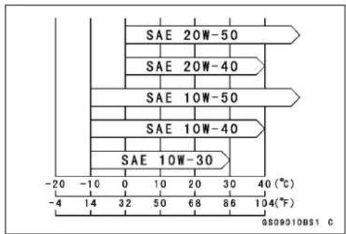
SAE10W-40
Capacity:1.1L(1.16USqt)
(Whenfilterisnotremoved)
1.2L(1.27USqt)
(whenfilterisremoved)
1.4L(1.48USqt)
(whenengineiscompletelydry)
NOTE
Although 10W-40engineoilistherecommendedoil formostconditions, the oil viscosity may need to be changed to accommodate atmospheric conditions in your riding area.
• Installtheoilfillerplug.
Torque- OilFillerPlug:2.5N·m(0.25kgf·m,22in·lb)
- Checktheoillevel(seeEngineLubricationchapter).
OilFilterChange
- Draintheengineoil(seeEngineOilchange).
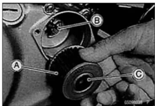
- Removetheoilfiltercoverbolts[A]andcover[B].
- Takeoffthefilter.
-
Removethespring. Front[C]
-
Replacethefilter[A]withanewone.
- Installthespring[B].
- Installthenewfiltersothatthegrommet[C]facetout-sideasshown.
CAUTION
If the filter is installed reversely, it can cause the engine seizure.

2-20PERIODICMAINTENANCE
PeriodicMaintenanceProcedures
- ReplacetheO-ring[A]withnewone.
- ApplygreasetotheO-ringandthegrommet[B].
• Installthecover[C]andtightenthecoverbolts.
Torque-OilFilterCoverBolts
(BN125-A1\~A3):9.8N·m(1.0kgf·m,87in·lb)
(BN125-A4 \~): 8.8 N·m (0.90 kgf·m, 78 in·lb)
- Pourinthespecifiedtypeandamountofoil(seeEngine OilChange).
OilScreenCleaning
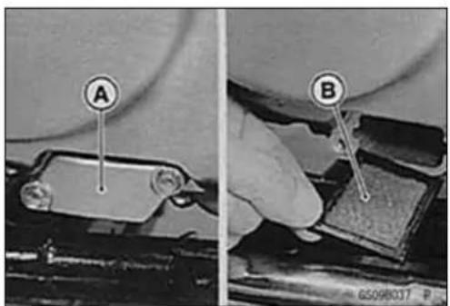
- Removetheoilscreencover[A].
- Removethegasket.
- Removetheoilscreen[B]fromtheclutchcover.
- Cleantheoilscreen[A]thoroughlywheneveritisremoved foranyreason.
- Cleantheoilscreenwithahigh-flashpointsolventand removeanyparticlesstucktoit.
WARNING
Cleanthescreeninawell-ventilatedarea,andtake carethatthereisnosparkorflameanywherenear theworkingarea.Becauseofthedangerofhighly flammableliquids,donotusegasolineorlow-flash pointsolvents.


natural_image
Isometric line drawing of a rectangular device with a grid pattern on the surface and a labeled point A (no text or symbols beyond label)@605000BS1 C
NOTE
○ Whilecleaningthescreen, checkforanymetalparticles that might indicate internalenginedamage.
- Checkthescreencarefullyforanydamage, holes, broken wires, gasketpullingoff.
★Ifthescreenisdamaged,replaceit.
• Installtheoilscreen[A].
Inserttheoilscreenwith"UP"mark[B]facingupandthe narrowside[C]ofthescreengoingfirst.
• Installthenewgasketandoilscreencover.
- Tightentheoilscreencoverbolts.
Torque-OilScreenCoverBolts
(BN125-A1\~A3):9.8N·m(1.0kgf·m,87in·lb)
(BN125-A4 \~): 8.8 N·m (0.90 kgf·m, 78 in·lb)

GG05014BS1 C
PeriodicMaintenanceProcedures
Wheels/Tires
Spoke Tightness Inspection
- Checkthatallthespokesaretightenedevenly.
★ Ifspoketightnessisunevenorloose, tightenthespoke nipplesevenly.
Torque - Spoke Nipples: 2.0 \~ 3.9 N·m (0.20 \~ 0.40 kgf·m, 17\~35in·lb)
- Checktherimrunout.
WARNING
Ifanyspokebreaks, it should bere placed immediately. A missingspoke places an additional load on the others spokes, which willeventually cause other spokes to break.
RimRunoutInspection
- Placethejackundertheframesothatthefront/rearwheel offtheground.
SpecialTool-Jack:57001-1238 - Inspecttherimforsmallcracks, dents, bending, or warping.
★ Ifthereisanydamagetotherim, it must bereplaced. - Removethewheelsandsetthemonthesuitablejig.
- Setadialgaugetothesideoftherim, and rotatetherim to measure axialrunout[A]. Thedifference between the highest and lowest dialreadings is the amount of runout.
- Setadialgaugetotheoutercircumferenceoftherim, androtatetherimtomeasureradialrunout[B]. Thedifferencebetween the highest and lowest dialreadings is the amount of runout.
★ Ifrimrunoutexceedstheservicelimit, checkthehubbearingsfirst. Replace them if they are damaged. If the problem is not to the bearings, correct their warp (runout). Acertain amount of interim warpcan be corrected by recent ring therim. Loosensomespokes and tighten others within the standard torque can be corrected by recent ring therim. If their imis badly bent, however, it must bere placed.
RimRunout(withtireInstalled)
Standard:
| Axial | TIR0.8mm(0.03in.)orless |
| Radial | TIR1.0mm(0.04in.)orless |
ServiceLimit:
| Axial | TIR2.0mm(0.08in.) |
| Radial | TIR2.0mm(0.08in.) |

2-22PERIODICMAINTENANCE
PeriodicMaintenanceProcedures
AirPressureInspection/Adjustment
- Removetheairvalvecap.
- Measure the air pressure with an air pressure gauge [A] when the tires are cold (thatis, when the motorcycle has not been ridden more than a mile during the past 3 hours).
★Adjust the tire air pressure according to the specifications if necessary.
AirPressure(whencold)
| Front | BN125-A1~ A2U | pto185kg(408lb) | 150kPa( 1.5 kgf/cm^2 ,21psi) |
| BN125-A3~ Upto155kg(342lb) | |||
| Rear | BN125-A1~ A2U | pto185kg(408lb) | 175kPa( 1.75 kgf/cm^2 ,25psi) |
| BN125-A3~ Upto155kg(342lb) | |||
- Installtheairvalvecapcertainlyafterairpressureinspection.

PeriodicMaintenanceProcedures
TireWearInspection
Asthetiretreadwearsdown, the tirebecomesmoresusceptibletopuncture and failure. An accepted estimate is that 90% of all tire failures occur during the last 10% of tread life (90% worn). So it is false economy and unsafetouse the tires until they are bald.
- Removeanyimbeddedstonesorotherforeignparticles fromthetread.
- Visuallyinspectthetireforcracksandcuts,replacingthe tireincaseofdamage.Swellingorhighspotsindicate internaldamage,requiringtirereplacement.
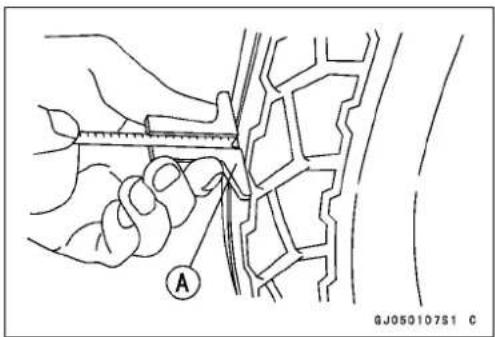
- Measurethetreaddepthatthecenterofthetreadwitha depthgauge[A].Sincethetiremaywearunevenly,take measurementatseveralplaces.
★ Ifanymeasurementislessthantheservicelimit,replace thetire.
TreadDepth
Standard:
| Front | (BN125-A1~ A2)4.5mm(0.18in.) |
| (BN125-A3~ A5)4.0mm(0.16in.) | |
| (BN125-A6~) 4 . 1 mm ( 0 . 1 6 in . ) | |
| Rear | 7.3mm(0.29in.) |
ServiceLimit:
Front 1mm(0.04in.)
Rear 2mm(0.08in.)
NOTE
○Mostcountriesmayhavetheirownregulationsrequiring aminimumtiretreaddepth;besuretofollowthem.
○Checkandbalancethewheelwhenatireisreplaced withanewone.

WARNING
Toensuresafehandlingandstability,useonlythe recommendedstandardtiresforreplacement,inflatedtothestandardpressure.
FinalDrive
DriveChainSlackInspection
- Checktoseethatthenotches[A]onthealignmentindicatorsonbothsidesareinthesamerelativepositionattherearend[B]oftheholeineachswingarm.
★ Iftheyarenot,adjustthechainslackandalignthem.

WARNING
Misalignmentofthewheelwill resultinabnormal wearandmayresultinanunsaferidingcondition.

natural_image
Close-up of a mechanical component with labeled parts A and B, connected by chains (no readable text or symbols)NOTE
○Cleanthechainifitisdirty, and lubricateitifitappears dry.
2-24PERIODICMAINTENANCE
PeriodicMaintenanceProcedures
- Setthemotorcycleuponitscenterstand.
○Rotatetherearwheeltofindthepositionwherethechain istightest.
○Measuretheverticalmovement(chainslack)[A]midway betweenthesprockets.
★ If the chains lack exceed the standard, adjust it.
ChainSlack
Standard: 25 \~ 40 mm (0.98 \~ 1.57 in.)
DriveChainSlackAdjustment
- Removethecotterpin[A]fromtherearaxlenut.
- Loosen:
TorqueLinkNut[B]
RearAxleNut[C]
BothChainAdjusterLocknuts[D] - TurnbothchainadjustersEevenlyuntilthedrivechain hasthecorrectamountofslack.
- Checktoseethatnotchesonthealignmentindicatorsare inthesamerelativepositiononbothsides.

WARNING
Misalignmentofthewheelwillresultinabnormal wearandmayresultinanunsaferidingcondition.
Torque-RearAxleNut:98N·m(10.0kgf·m,72ft·lb)
TorqueLinkNut:34N·m(3.5kgf·m,25ft·lb)

WARNING
If the axlenut and torquelink nut are not securely tightened, an unsaferiding condition may result.
- Turnthewheel, measure the chainslack again at the tightest position, and readjustif necessary.
- Insertanewcotterpin[A].
NOTE
When inserting the cotterpin, if the slots in then the not align with the cotterpin hole in the axle, tighten the nut clockwise [B] uptonextalignment.
○ Itshouldbewithin30degree.
○ Loosenonceandtightenagainwhentheslotgoespast thenaresthole.


PeriodicMaintenanceProcedures
- Bendthecotterpin[A]overthenut[B].
- Checktherearbrakeeffectiveness.
A WARNING
If the axle and torque link nuts are not securely tightened and the cotterpin and snappin are not installed, an unsaferiding condition may result.
- Tightenthechainadjusterlocknuts.
DriveChainWearInspection
- Removethechaincover(seeFinalDrivechapter).
- Rotatetherearwheeltoinspectthedrivechainfordamagedrollers, and loosepinsandlinks.
★ Ifthereisanyirregularity, replacethedrivechain.
★ Lubricatethedrivechainifitappearsdry. - Stretchthechaintautbyhanginga98N(10kg,20lb) weight[A]onthechain.
- Measurethelengthof20links[B]onthestraightpart[C]of thechainfromthepincenterofthe1stpintothepincenter ofthe21stpin.Sincethechainmaywearunevenly,take measurementsatseveralplaces.
★ Ifanymeasurementsexceedtheservicelimit,replace the chain.Also,replacethefrontandrearsprocketswhenthe drivechainisreplaced.
Chain20-linkLength
Standard: 254.0 \~ 254.6 mm (10.00 \~ 10.02 in.)
ServiceLimit:259mm(10.2in.)


WARNING
Ifthedrivechainwearexceedstheservicelimit,re- placethechainoranunsaferidingconditionmay result.Achainthatbrakesorjumpsoffthesprock- etscouldsnagontheenginesprocketorlockthe rearwheel,severelydamagingthemotorcycleand causingittogooutofcontrol.Forsafety,useonly thestandardchain.
StandardChain
BN125-A1\~A2
Make: ENUMACHAIN
Type: JointEndlessEK428SH-R
Link:132Links
BN125-A3 \~ (except the N, NU of BN125-A7 \~)
Make: DAIDO
Type: JointEndlessDID424HG
Link:132Links
130 Links (BN125-A7 \~ ) N, NU
N: CatalyticConverterModel
NU: CatalyticConverter(United KingdomModel)
2-26PERIODICMAINTENANCE
PeriodicMaintenanceProcedures
DriveChainLubrication
- Thechainshouldbelubricatedwithalubricantwhichwill bothpreventtheexteriorfromrustingandalsoabsorb shockandreducefrictionintheinteriorofthechain.
★Ifthechainisespeciallydirty, it should bewashed in diesel oilorkerosene, and afterward soaked in a heavy oil. Shakethechain while it is in the oil so that oil will penetrate to the inside of each roller. - Aneffective, good quality lubricants specially formulated for chainsis best for regular chain lubrication.
★Ifaspeciallubricantisnotavailable,aheavyoilsuchas SAE90ispreferredtoalighteroilbecauseitwillstayon thechainlongerandprovidebetterlubrication. - Applyoiltothesidesoftherollerssothatoilwillpenetrate totherollersandbushings.
- Wipeoffanyexcessoil. OilAppliedAreas[A]

Brakes
BrakePedalFreePlayInspection
- Checkthebrakepedalfreeplay[A]whenthepedalis pusheddownlightlybyhand.
BrakePedalFreePlay
Standard: 20 \~ 30 mm (0.79 in \~ 1.18 in.)
★Ifthepedalhasimproperplay,adjustit.
○Turntheadjustingnut[B]atthebrakecamleversothat theleverhasproperplay.
- Operatethepedalafewtimestoseethatitreturnstoits restpositionimmediatelyuponrelease.
- Rotatetherearwheeltocheckforbrakedrag.
- Checkbrakingeffectiveness.
★Ifthereisanydoubtastotheconditionsofthebrake, checkthebrakepartsforwearordamage.
- Check that the brakeling wear indicator [A] points within the USABLERANGE [B] when the brake lever is fully applied.
★ Ifitdoesnot, thebrakeshoesmustbereplacedandother brakepartsmustbeexamined.

natural_image
Mechanical assembly diagram showing two views of a robotic arm with labeled parts (A and B), no readable text or symbols present.
PeriodicMaintenanceProcedures
- Check that the front brake cam lever [A] comestoan 80° \~ 90° angle [C] with therear brakerod [B] when therear brake is fully applied.
★ Ifitdoesnot,removtheadjustingnut[D]andlever,then adjusttherearbrakecamleverangle. - Checkthebrakepedalfreeplay.
WARNING
Sinceacamleveranglegreaterthan90° reduces brakingeffectiveness, camleverangleadjustment should not be neglected. A change in cam lever angle is caused by wear of internal brake parts. Whenever the cam lever angle is adjusted, also check for drag and proper operation, taking particular note of the brakelining wear indicator position. In case of doubt, a braking effectiveness, disassemble and inspect all internal brake parts. Worn part scould cause the braketolock or fall.

BrakeShoeLiningWearInspection
- Removethebrakeshoes(seeBrakeschapter).
- Measuretheliningthickness[A],atafewpoint.
○Useacalipersorscale, andmeasureatseveralpoints.
ShoeLiningThickness
Standard: 3.85 \~ 4.15 mm (0.152 \~ 0.163 in.)
ServiceLimit:2mm(0.08in.)
★ Ifthelini ngthicknessisgreaterthantheservicelimit,replacebothshoesasaset.
• Installthebrakeshoes(seeBrakeschapter).
BrakePadWearInspection
- Removethepads.(seeBrakeschapter).
- Checktheliningthickness[A]ofthepadsinthecaliper.
★ Iftheliningthicknessofeitherpadislessthantheservice limit[B],replacebothpadsinthecaliperasaset. Brakepad[C]
BrakePadThickness
Standard:(BN125-A1\~A2)4.5mm(0.177in.) (BN125-A3\~)6.0mm(0.236in.)
ServiceLimit: 1mm(0.04in.)
• Installthepadsandpadbolts(seeBrakeschapter).
BrakeHoseandConnectionInspection
- Inspect the brake hose and fittings for deterioration, cracksandsignsofleakage.
○Thehighpressureinsidethebrakelinecancausefluidto leak[A]orthehosetoburstifthelineisnotproperlymaintained. Bendandtwisttherubberhosewhileexamining it.
★Replacethehoseifanycracks[B]orbulges[C]arenoticed.
★ Tightenanyloosefittings.
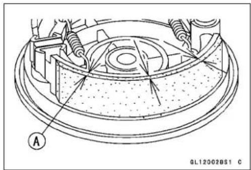
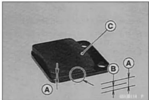

2-28PERIODICMAINTENANCE
PeriodicMaintenanceProcedures
BrakeFluidLevelInspection
- Check that the brake fluid level in the braker reservoir [A] is between the upper [B] and the lower [C] levelline.
NOTE
○ Holdthereservoirhorizontalbyturningthehandlebar whencheckingbrakefluidlevel.
★Ifthefluidlevelislowerthanthelowerlevelline,fillthe reservoirtotheupperlevellineinthereservoir.
WARNING
Donotmixtwobrandsoffluid. Changethebrake fluidinthebrakelinecompletelyifthebrakefluid mustberefilledbutthetypeandbrandofthebrake fluidthatisalreadyinthereservoirareunidentified. Afterchangingthefluid,useonlythesametypeand brandoffluidthereafter.
RecommendedDiscBrakeFluid Grade:DOT4
BrakeFluidChange
- Levelthebrakefluidreservoir.
- Removethereservoircap.
- Removetherubbercapfromthebleedvalve[A]onthe caliper.
- Attachaclearplastichose[B]tothebleedvalve,andrun theotherendofthehoseintoacontainer.
- Fillthereservoirwithfreshspecifiedbrakefluid.
- Changethebrakefluidasfollows:
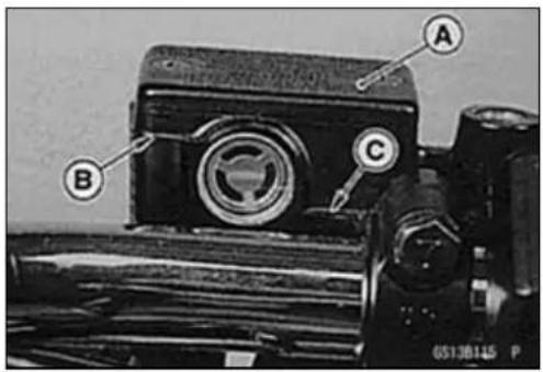

NOTE
○ Thefluidlevelmustbecheckedoftenduringthechangingoperationandreplenishedwithfreshbrakefluid. If thefluidinthereservoirrunsoutanytimeduringthe changingoperation,thebrakeswillneedtobebled sinceairwillhaveenteredthebrakeline.
○Repeatthisoperationuntilfreshbrakefluidcomesout fromtheplastichoseorthecolorofthefluidchanges.
Openthebleedvalve[A]. Pumpthebrakeleverandholdit[B]. Closethebleedvalve[C]. Releasethebrakelever[D].

PeriodicMaintenanceProcedures
- Removetheclearplastichose.
• Installthereservoircap. - Tightenthebleedvalve, and installtherubbercap.
Torque-CaliperBleedValve:7.8N·m(0.80kgf·m,69in·lb) FrontBrakeReservoirCapScrews:2.5N·m(0.25 kgf·m,22in·lb)
- Afterchangingthefluid, checkthebrakeforgoodbraking power, nobrakedrag, andnofluidleakage.
★ If necessary, bleed the air from the lines (see Brake Line Bleeding).
BrakeLineBleeding
Thebrakefluidhasaverylowcompressioncoefficientso thatalmostallthemovementofthebrakeleveristransmitteddirectlytothecaliperforbrakingaction.Air,however,is easilycompressed.Whenairentersthebrakelines,brake levermovementwillbepartiallyusedincompressingthe air.Thiswillmaketheleverfeelspongy,anditwillbealoss inbrakingpower.
WARNING
Besuretobleedtheairfromthebrakelinewhen-everbrakeleveractionfeelssoftorspongyafter thebrakefluidischanged,orwheneverabrakeline fittinghasbeenloosenedforanyreason.
- Removethereservoircap, and fill the reservoir with fresh brake fluid to the upper level in the reservoir.
- Withthereservoircapoff,slowlypumpthebrakelever severaltimesuntilnoairbubblescanbeseenrisingup throughthefluidfromtheholesatthebottomofthereservoir.
○ Bleedtheaircompletelyfromthemastercylinderbythis operation.
• Installthereservoircap. - Removetherubbercapfromthebleedvalveonthe caliper.
- Attachaclearplastichosetothebleedvalve, andrunthe otherendofthehoseintoacontainer.
- Bleedthebrakelineandthecaliperasfollows.
○ Repeat this operation until nomore air can be seen coming out into the plastichose. - Pumpthebrakeleveruntilbecomeshard, and apply thebrakeandholdit[A].
- Quickly open and close [B] the bleed valv while holding the brake applied.
- Releasethebrake[C].
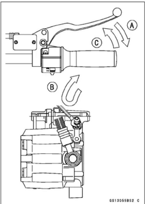
NOTE
○ Thefluidlevelmustbecheckedoftenduringthebleedingoperationandreplenishedwithfreshbrakefluidas necessary. If thefluidinthereservoirrunscompletely outanytimeduringbleeding, thebleedingoperation must bedoneoveragainfromthebeginningsinceair will have enteredtheline.
○ Tapthebrakehoselightlyfromthecalipertothereservoirformorecompletebleeding.
- Removetheclearplastichose.
- Tighten:
Torque-CaliperBleedValve:7.8N·m(0.80kgf·m,69in·lb)
FrontBrakeReservoirCapScrews:2.5N·m(0.25 kgf·m,22in·lb)
- Checkthefluidlevel.
- Afterbleedingisdone, checkthebrakeforgoodbraking power, nobrakedrag, andnofluidleakage.

WARNING
When working with the disc brake, observ the precautions listed below.
- Neverreuseoldbrakefluid.
- Donotusefluidfromacontainerthathasbeenleft unsealedorthathasbeenopenforalongtime.
-
Donotmixtwotypesandbrandsoffluidforusein thebrake. Thislowersthebrakefluidboilingpoint andcouldcausethebraketobeineffective. It may also cause therubberbrakepartstodeteriorate.
-
Don'tleavethereservoircapofforanylengthof timetoavoidmoisturecontaminationofthefluid.
-
Don't changethe fluid in therain or when a strong wind is blowing.
-
Except forthediscpadsanddisc, use only disc brake fluid, isopropyl alcohol, orethyl alcohol for cleaning brake parts. Donot use any other fluid for cleaning these parts. Gasoline, engine oil, or any other petroleum distillate will cause deterioration of the rubber parts. Oil spilled on any part will be difficult to wash off completely and while eventually deteriorate the rubber used in the disc brake.
-
When handling the discpadsordisc, be careful that nodiscbrakefluidoranyoilgetsonthem. Cleanoff any fluidorol that in advertently gets on the pads or disc with a high-flash points solvent. Donotuse one which will leave an oily residue. Replacethepads with new ones if they cannot be cleaned satisfactorily.
-
Brake fluid quickly ruins painted surfaces; any spilled fluid should be completely washed away immediately.
-
If any of the brakeline fittings or the bleed valve is opened at any time, the AIR MUST BE BLED FROM THE BRAKE LINE.
PeriodicMaintenanceProcedures
Brake/MasterCylinderCupandDustSeal Replacement
- RefertotheMasterCylinderintersectionintheBrakeschapter forBrake/MasterCylinderCupandDustSealReplacement.
CaliperPiston/DustSealsReplacement
- RefertotheCaliperssectionintheBrakeschapterfor CaliperPiston/DustSealsReplacement.
BrakeLightSwitchInspection
FrontBrakeLightTimingInspection
• Turnontheignitionswitch.
- Thebrakelightshouldgoonwhenthefrontbrakeisapplied.
★ Ifitdoesnot, replacetheswitch.
RearBrakeLightTimingInspection
• Turnontheignitionswitch.
- Checktheoperationoftherearbrakelightswitchbydepressingthebrakepedal.
- Ifitdoesnotasspecified,adjustthebrakelighttiming.
BrakeLightTiming
Standard: On After about 10 mm (0.39 in.) of pedal travel [A]
RearBrakeLightTimingAdjustment
- Whileholdingtheswitchbody,turntheadjustingnut[A] toadjusttheswitch.
CAUTION
To avoid damaging the electrical connections in sidetheswitch, besure that the switch body does not turn during adjustment.
NOTE
○Brakelightturnsonsoonerastheswitchbodyrises[B], andturnsonlaterastheswitchbodylowers[C].
BrakeCableReplacement
- Wheneverthebrakecableisremoved,lubricateit.
- Withthecabledisconnectedatbothends, thecable shouldmovefreely[A]withinthecablehousing.
★ Ifcablemovementisnotfreeafterlubricating,ifthecable isfrayed[B],orifthecablehousingiskinked[C],replace thecable.

natural_image
Close-up of a mechanical component with labeled parts (A) and no visible text or symbols

2-32 PERIODIC MAINTENANCE
PeriodicMaintenanceProcedures
Suspension
FrontForkOilChange
- Removethefrontfork(seeSuspensionchapter).
- Holdtheoutertubeverticallyinavise.
- Unscrewthetopplugoutoftheinnertube.
- Remove:
Spacer[A]
ForkSpringSeat[B]
ForkSpring[C]
- Pourouttheforkoiltothecontainer[C]withtheforkup-sidedown[B].
OPumptheoutertube[A]upanddowntoexpeltheoilfrom thefork. - Holdingtheforktubeupright, presstheinnertubeallthe waydown.
NOTE
○ Thespringshouldnotbeinstalled.
- Fillthefrontforkwiththespecifiedoil.
ForkOilViscosity:SHOWASS-8orequivalent ForkOilCapacity
(whenchangingoil):Approx.165mL(5.58USoz.)
- Waitforaboutfiveminutessothatanysuspendedairbubblesansurface.
- Measuretheoillevel, usingtheforkoillevelgauge[A].
SpecialTool-ForkOilLevelGauge:57001-1290
○Setthegaugestopper[B]sothatitslowersideshowsthe oilleveldistancespecified[C].
○Insertthegaugetubeintotheinnertube[D]andposition thestopperacrossthetopoftheinnertubeE.
OPullthehandleslowlytodrawouttheexcessoiluntilno moreoilcomesupthetube.
★Ifnooilisdrawnout,thereisnotenoughoilinthefork. Pourinsomemoreoil,thendrawouttheexcess.
FrontForkOilLevel(Fullycompressedwithoutfork spring)
Standard:218±2mm(8.58±0.08in.)


PeriodicMaintenanceProcedures
- Installtheforkspring[A]withthesmallerendfacing[B] downward.
- Install: ForkSpringSeat Spacer
- Repeatthesameprocedureforanotherfrontfork.
- Installthefrontfork(seeSuspensionchapter).
FrontForkOilLeakInspection
- Visually inspect the front forks [A] for oilleakage, scoring or scratches on the outersurface of the innertubes.
★Replaceorrepairanydefectiveparts,ifnecessary.


natural_image
Close-up of a bicycle wheel and suspension bracket with labeled component A (no text or symbols beyond label)RearShockAbsorberOilLeakInspection
- Visually inspect therearshockabsorbers[A]foroilleakage.
★ Iftheyareoilleaked, oneunitfeelsweakerthantheother, replacebothshockabsorberasaset.

natural_image
Close-up of a motorcycle's wheel and suspension system (no visible text or symbols)
SwingarmPivotLubrication
- Removetheswingarm(seeSuspensionchapter).
- Using high-flash-points solvent, wash the following parts, and apply plenty of molybdenum disulfide greasethem.
NeedleBearings[A]
GreaseSeals[B]
Sleeve[C]
SwingarmPivotShaft(exceptforthreads)[D]
○ Thispreventstheshaftandtheboltfromrustingorseizing.
2-34PERIODICMAINTENANCE
PeriodicMaintenanceProcedures
Steering
SteeringInspection
- Checkthesteering.
○Liftthefrontwheeloffthegroundusingthejack[A].
SpecialTool-Jack:57001-1238
With the front wheelpointing straight ahead, alternately tapeachendof the handlebar. The front wheel should swing fully left and right from the force of gravity until the fork hit the stop.
★Ifthewheelbindsorcatchesbeforethestop, thesteering istootight.
○Feelforsteeringloosenessbypushingandpulling[A]the forks.
★Ifyoufeellooseness,thesteeringistooloose.
NOTE
○ Thecablesandwiringwillhavesomeeffectonthemotionoftheforkwhichmustbetakenintoaccount.Be surethewiresandcablesareproperlyrouted.
○ Thebearingsmustbeingoodconditionandproperly lubricatedinorderforanytesttobevalid.
SteeringAdjustment
- Loosen:
FrontForkLowerClampBolts(bothsides)[A] SteeringStemHeadBolt[B]
- Liftthefrontwheeloffthegroundusingthejack.
SpecialTool-Jack:57001-1238
- Adjustthesteering.
SpecialTool-SteeringStemNutWrench:57001-1100
★Ifthesteeringistootight,loosenthestemnut[C]afractionofaturn.
★Ifthesteeringistooloose,tightenthestemnutafraction ofaturn.
NOTE
○ Turnthestemnut1/8turnatatimemaximum.
Torque-SteeringStemNut:4.9N·m(0.50kgf·m,43in·lb)
- Tighten:
Torque-SteeringStemHeadBolt:44N·m(4.5kgf·m,33ft·lb)
FrontForkClampBolts(Lower):34N·m(3.5 kgf·m,25ft·lb)
- Checkthesteeringagain.
★ If the steering is still toight tortoolose, inspect the steering parts.

natural_image
Close-up of a motorcycle wheel and its mechanical assembly with labeled component A (no readable text or symbols)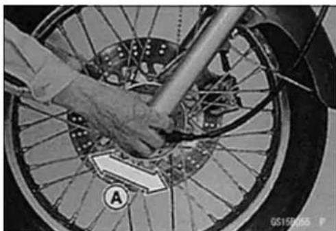
natural_image
Close-up of a bicycle wheel with a hand adjusting the rim, showing no visible text or symbols.
PeriodicMaintenanceProcedures
SteeringStemBearingLubrication
- Removethesteeringstem(seeSteeringchapter).
- Usingahigh-flashpointsolvent, washtheupperand lowersteelballs.
- Wipealltheoldgreaseofftheupperandlowerouter races.
- Visuallychecktheracesandballs.
★Replacethebearingassembliesiftheyshowwearor damage. - Applygreaseliberallytotheupperandlowerraces,and stickthesteelballs[A]inplacewithgrease.
- Installthesteeringstem(seeSteeringchapter), and adjustthesteering(seeSteeringAdjustment).

ElectricalSystem
BatteryElectrolyteLevelInspection
- Visuallychecktheelectrolytevelinthebattery.
★ Ifthelevellineofelectrolyteinanycellisbelowthelower levelline[A]onthebatterycase,addistilledwateronly tothatcelluntilthelevelisattheupperlevelline[B].
CAUTION
Ordinarytapwaterisnotasubstitutefordistilled waterandwillshortenthelifeofthebattery.
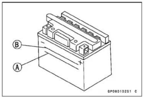
SparkPlugCleaning/Inspection
- Cleanthesparkplug, preferablyinasandblastingdevice, andthencleanoffanyabrasiveparticles. Theplugmay also be cleaned using a high-flash points solvent and a wire brushor others suitable tool.
★ Ifthesparkplugcenterelectrode[A]and/orsideelectrode[B]arecorrodedordamaged,oriftheinsulator[C]iscracked,replacetheplug. - Usethestandardsparkplugoritsequivalent.

SparkPlugGapInspection
- Measurethegap[D]withawire-typethicknessgauge.
★ Ifthegapisincorrect, carefully bend the side electrode with suitable tool to obtain the correct gap.
Spark Plug Gap: 0.7 \~ 0.8 mm (0.028 \~ 0.031 in.)
2-36PERIODICMAINTENANCE
PeriodicMaintenanceProcedures
GeneralLubrication
Lubrication
- Beforelubricatingeachpart,cleanoffanyrustyspotswith rustremoverandwipeoffanygrease,oil,dirt,orgrime.
- Lubricatethepointslistedbelowwithindicatedlubricant.
NOTE
○ Wheneverthevehiclehasbeenoperatedunder wetorrainyconditions,orespeciallyafterusinga high-pressurewaterspray,performthegenerallubrication.
Pivots:LubricatewithMotorOil
Sidestand BrakePedal ClutchLever
Points:LubricatewithGrease.
ThrottleInnerCableUpperEnds[A]
SpeedometerInnerCable*
ClutchInnerCableUpperEnd
BrakeLever**
(*): Greasethelowerpartoftheinnercablesparingly.
(**):Applysiliconegrease.
Cables:LubricatewithCableLubricant.
ThrottleInnerCable
ClutchInnerCable
- Lubricatethecablesbyseepingtheoilbetweenthecable andhousing.
○Thecablemaybelubricatedbyusingacommercially availablepressurecablelubricatorwithanaerosolcable lubricant. - With the cabled disconnected at the both ends, the cable should move freely [A] within the cable housing.
★Ifcablemovementisnotfreeafterlubricating,ifthecable isfrayed[B],orifthecablehousingiskinked[C],replace thecable.
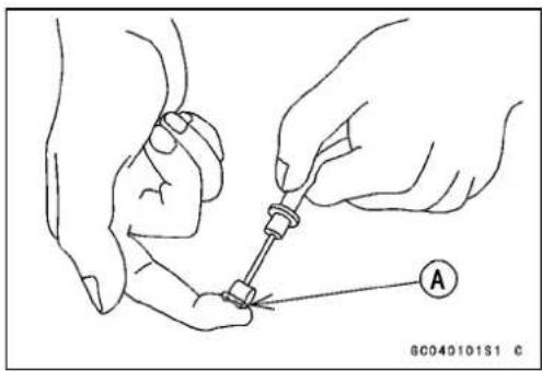

natural_image
Line drawing of hands using a tool to apply liquid onto a cylindrical object (no text or symbols)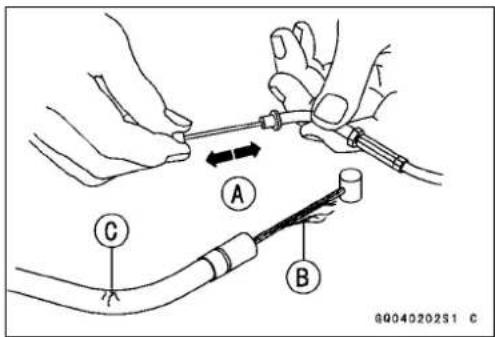
PeriodicMaintenanceProcedures
Nut, Bolt, and Fastener Tightness Inspection
TightnessInspection
- Checkthetightnessoftheboltsandnutslistedhere. Also, checktoseethateachcotterpinisinplaceandingood condition.
NOTE
○Fortheenginefasteners, checkthetightnessofthem whentheengineiscold(atroomtemperature).
★ Ifthereareloosefasteners,retightenthemtothespecifiedtorquefollowingthespecifiedtighteningsequence. Refertotheappropriatechapterfortorquespecifications. Iftorquespecificationsarenotintheappropriatechapter, seetheStandardTorqueTableinthissection.Foreach fastener,firstloosenitby1/2turn,thentightenit.
★ Ifcotterpinsaredamaged, replacethemwithnewones.
Nut, Boltand Fastenertobechecked
Wheels:
FrontAxleNut
RearAxleNutCotterPin
RearAxleNut
FinalDrive:
ChainAdjusterLocknuts
RearSprocketNuts
Brakes:
BrakeLeverPivotNut
BrakePedalCotterPin
BrakeRodJointCotterPin
TorqueLinkNut
BrakeCamLeverNut
CaliperMountingBolts
FrontMasterCylinderClampBolts
Suspension:
FrontForkClampBolts
FrontFenderBolts
RearShockAbsorberBoltsandNuts
SwingarmPivotNut
Steering:
StemHeadBolt
HandlebarHolderClampNuts
Engine:
ThrottleCableAdjusterLocknut
EngineMountingBoltsandNuts
ShiftPedalBolt
MufflerMountingBoltsandNuts
ClutchCableAdjusterLocknut
ClutchLeverPivotNut
Others:
SidestandBoltandNut
FrontFootpegMountingBolts
RearFootpegMountingBolts
FuelSystem
TableofContents
Exploded View 3-2
Specifications 3-8
Special Tools 3-10
Throttle Grip and Cables 3-11
Free Play Inspection 3-11
Free Play Adjustment.... 3-11
Throttle Cable Installation 3-11
Throttle Cable Lubrication and Inspection 3-11
Carburetor 3-12
Idle Speed Inspection 3-12
Idle Speed Adjustment.... 3-12
Service Fuel Level Inspection 3-12
Service Fuel Level Adjustment 3-13
Fuel System Cleanliness Inspection 3-14
Carburetor Removal.... 3-14
Carburetor Installation.... 3-15
Carburetor Disassembly 3-15
Carburetor Assembly 3-17
Carburetor Cleaning.... 3-18
Carburetor Inspection 3-19
Air Cleaner 3-21
Air Cleaner Element Removal.... 3-21
Element Cleaning and Inspection 3-21
Air Cleaner Draining.... 3-21
Air Cleaner Housing Removal 3-22
Air Cleaner Housing Installation.... 3-22
Fuel Tank 3-23
Fuel Tank Removal 3-23
Fuel Tank Installation 3-23
Fuel Tank Inspection 3-23
Fuel Tank Cleaning 3-24
Fuel Tap Removal 3-24
Fuel Tap Installation 3-24
Fuel Tap Inspection 3-25
Evaporative Emission Control System ( California Model Only) 3-26
Parts Removal/Installation 3-26
Hose Inspection 3-26
Separator Inspection 3-26
Separator Operation Test 3-27
Canister Inspection 3-27

ExplodedView
| No.Fa | stener | Torque | Remarks | ||
| N·mkgf | mft·lb | ||||
| 1 | Upper Chamber Cover Mounting Screws | 3.5 | 0.36 | 31 in·lb | |
| 2 | Spring Seat Screws | 0.8 | 0.080 | 7 in·lb | |
| 3 | ChokeLeverSetScrew | 0.80.08 | 07 in·lb | L | |
| 4 | ChokeLeverPivotScrew | 2.00.2017in·lb | |||
| 5 | Pilot Air Jet | 1.8 | 0.18 | 15 in·lb | |
| 6 | CoastingEnricherCoverScrews | 2.00.20 | 17in·lb | ||
| 7 | Pilot Jet | 0.8 | 0.080 | 7 in·lb | |
| 8 | Main Jet | 1.8 | 0.18 | 15 in·lb | |
| 9 | Float Valve Holder Screw | 2.0 | 0.20 | 17 in·lb | |
| 10 | Choke Plunger Cap | 3.9 | 0.40 | 35 in·lb | |
| 11 | Float Bowl Screws | 2.0 | 0.20 | 17 in·lb | |
| 12 | CarburetorDrainPlug | 2.00.20 | 17in·lb | ||
- Throttleable (accelerator)
- Throttleable(decelerator)
15.Plug(CA,CH,US)
16.Pilotscrew - Valveneedle
18.Needlejet
19.Float
20.Jetneedle
21.BN125-A1\~A2
22.BN125-A3\~
CL:Applycablelubricant.
G:Applygrease.
L: Applyanon-permanentlockingagent.
CA:Canada
CH:Switzerland
US:UnitedStates
ExcepttheCaliforniaModel

ExplodedView
| No.Fa | stener | Torque | Remarks | ||
| N·mkgf | ·mft·lb | ||||
| 1Fuel | TapPlateScrews0.80.0807 i n · l b | ||||
| 2 | Fuel Tap Diaphragm Cover Screws | 1.0 | 0.10 | 9 in·lb | |
| 3Fuel | TapMountingBolts | 2.5 | 0.25 | 22 in·lb | with White Washer |
| 4.9 | 0.50 | 43 in·lb | with Black Washer | ||
- Catch tank
- Vacuum switch valve (For the AT, CH, DE of BN125-A1 \~ A2 and All Models of BN125-A3 \~)
- FortheAT, CH, DEofBN125-A1, and Except the EUR of BN125-A7\~
- On and after EUR of BN125-A7
- Air cleanerelement
OR: Apply high-quality-foam-air filter oil.
AT: Austria
CH:Switzerland
DE:Germany
EUR: Europe
CaliforniaModel

ExplodedView
| No.Fa | stener | Torque | Remarks | ||
| N·mkgf | f·mft·lb | ||||
| 1Fuel | ITapPlateScrews0.80.0807 i n · l b | ||||
| 2 | Fuel Tap Diaphragm Cover Screws | 1.0 | 0.10 | 9 in·lb | |
| 3Fuel | ITapMountingBolts | 2.5 | 0.25 | 22 in·lb | with White Washer |
| 4.9 | 0.50 | 43 in·lb | with Black Washer | ||
-
Catch tank
-
Vacuum switchvalve
6.Canister
7.Separator
8.BN125-A5 only
-
On and after BN125-A7
-
Air cleanerelement
OR: Apply high-quality-foam-air filter oil.
Specifications
| ItemStandard | |
| Throttle Grip Free Play | 2 ~ 3 mm (0.08 ~ 0.12 in.) |
| CarburetorMake,TypeMIKUNIBS28IdleSpeed1300±50r/min(rpm)PilotScrew(TurnsOut)1 5 / 8Service Fuel LevelFloatHeight19.4±2mm(0.76±0.08in.)MainJet#105NeedleJet(No.)0-8(807)JetNeedleMark4DH24-3PilotJet(SlowJet) #30PilotAirJet(SlowAirJet) #95ThrottleValve | 3.0(BN125-A7~, N , N U )(US,CA,CH)-1 ~ 3 mm (0.04 ~ 0.12 in.) below from the bottom edge of theofthecarburetorbodyskirt.#125(US,CA)#122.5(BN125-A7~, N , N U )0-8M(891)(US,CA)0-7M(891)(BN125-A7~, N , N U )4C17-1(US,CA)4C31-2(BN125-A7~,N,NU)#32.5(US,CAandBN125-A7~,N,NU)#90(US,CA)#70 (BN125-A6 ~ US, CA and BN125-A7~, N, NU)#110#105(US,CAa ndBN125-A7~,N,NU) |
| Air Cleaner Element OilGradeViscosity | High-quality-foam-air-filter oilAPISE,SF,orSGclassSAE30 |
CA:Canada
CH:Switzerland
US:UnitedStates
N: No Catalytic Converter Model
NU:NoCatalyticConverter(UnitedKingdomModel)
Specifications
Pilotscrew[A]
Plug [B] (US, CA, CH)
Pilotairjet[C]
Jetneedle[D]
ThrottlevalveE
Pilotjet[F]
Needlejet[G]
Mainjet[H]
Float[l]
Valveseat[J]
Valveneedle[K]
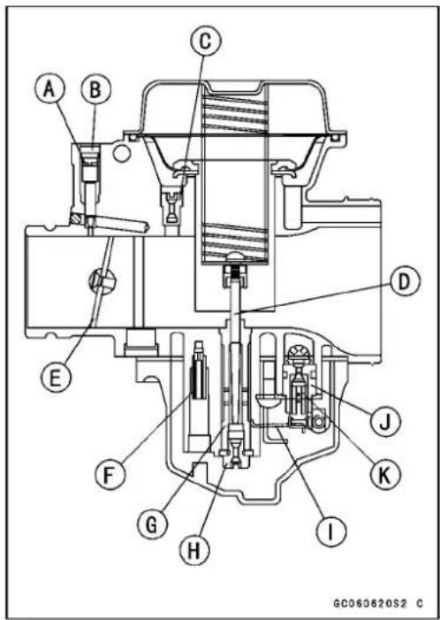
3-10FUELSYSTEM
SpecialTools
FuelLevelGauge: 57001-1017
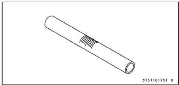
natural_image
Technical line drawing of a cylindrical mechanical part with internal grooves (no text or symbols)CarburetorDrainPlugWrench,Hex3:57001-1269
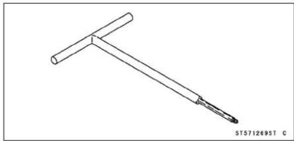
natural_image
Line drawing of a T-shaped tool or tool with a handle and base, no text or symbols presentThrottleGripandCables
FreePlayInspection
- RefertotheThrottleGripFreePlayInspectioninthePeriodicMaintenancechapter.
FreePlayAdjustment
- RefertotheThrottleGripFreePlayAdjustmentinthe PeriodicMaintenancechapter.
Throttle Cable Installation
- InstallthethrottlecableinaccordancewiththeCable, Wire,andHoseRoutingsectionintheAppendixchapter.
- Installtheupperendsofthethrottlecablesinthegrip afterinstallingthelowerendsofthethrottlecableonthe carburetor.
- Tighten:
Torque-HandlebarSwitchHousingScrews:3.4N·m(0.35 kgf·m,30in·lb)
- AfterInstallation,adjustthecableproperly.
WARNING
Operationwithincorrectlyroutedorimproperlyadjustedcablescouldresultinanunsaferidingcondition.
Throttle Cable Lubrication and Inspection
- Whenever the cable are removed, or in accordance with the Periodic Maintenance Chart, lubricatethethrottle cable (see General Lubrication in Periodic Maintenance chapter).
- Applyathincoatingofgreasetothecableupperend.
- Usethepressurecablelubbertolubricatethecable.
- With the cabled disconnected at both ends, the cable should move freely in the cable housing.
★ Ifthecablemovementisnotfreeafterlubricating,ifthe cableisfrayed,orifthehousingiskinked,replacethe cable.
Carburetor
IdleSpeedInspection
- RefertotheldleSpeedInspectioninthePeriodicMaintenancechapter.
IdleSpeedAdjustment
- RefertotheIdleSpeedAdjustmentinthePeriodicMaintenancechapter.
ServiceFuelLevelInspection
WARNING
Gasolineisextremelyflammableandcanbeexplosiveundercertainconditions.Turntheignition switchOFF.Donotsmoke.Makesuretheareais well-ventilatedandfreefromanysourceofflame orsparks;thisincludesanyappliancewithapilot light.
- Removethecarburetor, and hold it upright on a stand (see Carburetor Removal).
- Prepareanauxiliaryfueltankandconnectthefueltapto thecarburetorusingasuitablehose.
- Prepareasuitablefuelhose.
- Connectthefuellevelgauge[A]tothecarburetorfloat bowlwiththefuelhose.
SpecialTool-FuelLevelGauge:57001-1017
- Holdthegaugeverticallyagainstthesideofthecarbutorbodysothatthemiddleline[B]isseveralmillimeters higherthanthebottomedge[C]ofthecarbutorbody.
- TurnthefueltaptotheONpositiontofeedfueltothe carburetor, thenturnoutthecarburetordrainplug[D]a fewturns.
SpecialTool-CarburetorDrainPlugWrench, Hex3: 57001-1269
- Waituntilthefuellevelinthegaugesettles.
- Keepingthegaugevertical, slowly lower the gauge until the "middle" line is even with the bottom edge E of the carburetorbody.
NOTE
○ Do not lower the “middle” line below the bottom edge of thecarburetorbody. Ifthegaugeisloweredandthen raisedagain, thefuellevelmeasured showssomewhat higher than the actual fuel level. If the gauge is lowered too far, dump the fuel out of it into suitable container and starttheprocedureoveragain.
- Read the fuel level in the gauge and compare to the specification.
ServiceFuelLevel
Standard: 1 \~ 3 mm (0.04 \~ 0.12 in.)
below from the mating surface of the float bowl.
- Tightenthe drainplug, turnthe fueltaptotheOFFposition andremovethefuellevelgauge.
★ If the fuel level is incorrect, adjustit (see Service Fuel Level Adjustment).

Carburetor
ServiceFuelLevelAdjustment
WARNING
Gasolineisextremelyflammableandcanbeexplosiveundercertainconditions.Turntheignition switchOFF.Donotsmoke.Makesuretheareais well-ventilatedandfreefromanysourceofflame orsparks;thisincludesanyappliancewithapilot light.
- Removethecarburetor, and drain the fuel into as suitable container.
- Removethefloatbowlscrews[A]andfloatbowl[B].
- Slideoutthepivotpin[A]andremovethefloat[B].
- Whenremovingandinstallingthepivotpin,notethefollowings.
○Becarefulnottosnapthepinholderleg[C].
○Whenremovingit,tap[D]theleftendofthepin.
Wheninstallingit, pressEtherightendofthepin. Front[F]
- Bendthetang[A]onthefloatarmveryslightlytochange thefloatheight.
- Driveinthepivotpintoinstallthefloat[C].
- Removethefloatchambergasket.
- Measurethefloatheight[D]tiltingthecarburetorsothat thetangonthefloatjusttouchestheneedlerodinthe floatvalve.
○ Increasingthefloatheightlowersthefulevelelanddecreasingthefloatheightraisesthefuellevel. FloatBowlMatingSurface[A] FloatValveNeedleRod(contactedbutunloaded)[B]
FloatHeight
Standard:19.4±2mm(0.76±0.08in.)
NOTE
○Donotpushtheneedlerodinduringfloatheightmeasurement.
- Assemblethecarburetor, andrecheckthefuellevel.
★ Ifthefuellevelcannotbeadjustedbythismethod,the floatorthefloatvalveisdamaged.


Carburetor
FuelSystemCleanlinessInspection
WARNING
Gasolineisextremelyflammableandcanbeexplosiveundercertainconditions.Turntheignition switchOFF.Donotsmoke.Makesuretheareais well-ventilatedandfreefromanysourceofflame orsparks;thisincludesanyappliancewithapilot light.
- Connectasuitablehosetothefittingatthebottomofthe carburetorfloatbowl.
- Runthelowerendofthehoseintoasuitablecontainer.
- TurnthefueltaptothePRIposition.
- Turnoutthedrainplug[A]afewturnsanddrainthefloat bowl.
Front[B]
SpecialTool-CarburetorDrainPlugWrench,Hex3:57001-1269
- Checktoseeifwaterordirtcomesout.
- TightenthedrainplugandturnthefueltaptotheON position.
Torque-CarburetorDrainPlug:2.0N·m(0.20kgf·m,17in·lb)
★Ifanywaterordirtappearsduringtheaboveinspection, cleanthefuelsystem(seeCarburetorCleaningandFuel TankCleaning).
CarburetorRemoval
WARNING
Gasolineisextremelyflammableandcanbeexplosiveundercertainconditions.Turntheignition switchOFF.Donotsmoke.Makesuretheareais well-ventilatedandfreefromanysourceofflame orsparks;thisincludesanyappliancewithapilot light.
- Remove:
FuelTank(seeFuelTankRemoval) ThrottleCableLowerEnds[A] - Move back the air cleaner housing (see Air Cleaner HousingRemoval).

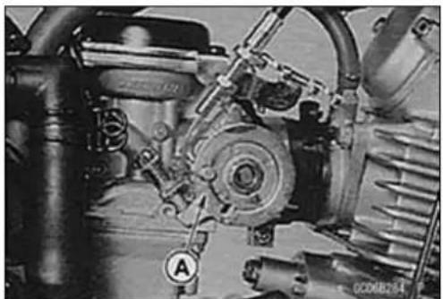
natural_image
Close-up mechanical assembly showing gears and springs (no visible text or symbols)Carburetor
- Loosenthecarburetorholderclamp[A]andaircleaner ductclamp.
- Pullthecarburetoroutoftheaircleanerductend[B], and then pullitoutofthecarburetorholder[C] from the vehicle's rightside.
• Takeoutthecarburetor. - Stuffpiecesoflint-free,cleanclothintothecarburetor holderandtheaircleanerducttokeepdirtoutoftheengineandaircleaner.
WARNING
Ifdirtordustisallowedtopassthroughintothe carburetor, thethrottlemaybecomestuck, possibly causinganaccident.
CAUTION
Ifdirtgetsthroughintotheengine,excessiveenginewearandpossiblyenginedamagewilloccur.
Carburetor Installation
- Wheninstallingthecarburetorintothecarburetorholder, fittheridge[B]ofthecarburetorintotherecess[A]ofthe carburetorholder.
- Tightentheclampscrews[A]sothatfacethescrewpositionandscrewheaddirection.
- Checkfuelleakagefromthecarburetor.
WARNING
Fuelspilledfromthecarburetorishazardous.
- Adjust the following items if necessary. Throttle Cable IdleSpeed
CarburetorDisassembly
- Removethecarburetor(seeCarburetorRemoval).
WARNING
Gasolineisextremelyflammableandcanbeexplosiveundercertainconditions.Turntheignition switchOFF.Donotsmoke.Makesuretheareais well-ventilatedandfreefromanysourceofflame orsparks;thisincludesanyappliancewithapilot light.
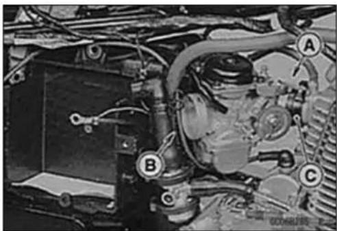
natural_image
Close-up of a mechanical engine assembly with labeled parts (A, B, C), no visible text or symbols beyond labels.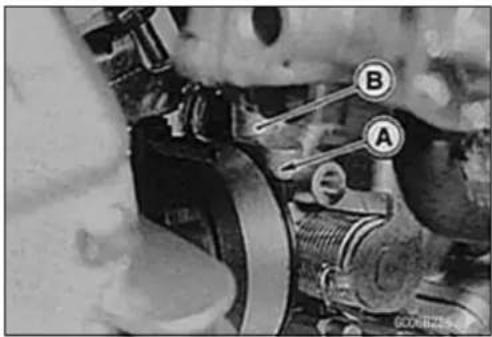
natural_image
Close-up mechanical assembly showing components labeled A and B (no readable text or symbols beyond labels)
3-16FUELSYSTEM
Carburetor
- Remove:
UpperChamberCover[A]
VacuumPistonandDiaphragm
CAUTION
Duringcarburetordisassembly, the careful not to damagehediaphragm. Never use a sharpedgeto removal of diaphragm.
- Removethespringseatscrews[D].
- Removethejetneedle[A]fromthevacuumpiston[B] alongwiththespringseat[C].
- Thepilotscrewissetatthefactoryandshouldnotbe removed. Butifnecessary, removethepilotscrewas follows.
- ReplacetheO-ringwithanewone.
○FortheSwiss,UnitedStates.andCanadamodels,pry outthepilotscrewplugwithanawlorothersuitabletool. - Turninthepilotscrewandcountthenumberofturnsuntil itseatsfullybutnottightly,andthenremovethescrew. Usethisnumberofturnstosetthescrewtoitsoriginal positionduringassembly.
NOTE
○Acarburetorhasdifferent"turnsout"ofthepilotscrew foreachindividualunit. Whensettingthepilotscrew, usethe "turnsout" determined during disassembly. Use the specification in this manual only if the original number is unknown.
- Remove:
FloatBowl
FloatPivotPin[A]
Float[B]withFloatValveNeedle
PilotJet[C]
MainJet[D]
- Pushtheneedlejet[A]outfromtheinsideofthecarbure-torborewithyourfinger.

natural_image
Close-up of a mechanical component with a labeled section (A) and no visible text or symbols on the main subject.

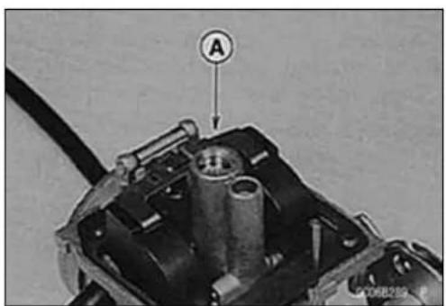
natural_image
Close-up of a mechanical component with labeled point A (no readable text or symbols beyond label)Carburetor
- Removethecoastingenrichercover.
- Removethediaphragm[A].

natural_image
Close-up of a mechanical component with a tool inserted, showing internal parts and a labeled section A (no readable text or symbols)CarburetorAssembly
- Turninthepilotscrew[A]fullybutnottightly, and then backitoutthesamenumberofturncountedduringdisassembly.
- FortheSwiss,UnitedStates.andCanadamodels,drive inanewplug[B]inthepilotscrewholeofthecarburetor body[C]asshown.

CAUTION
Donotforcetheneedlejetandmainjetorover-tightenthem. They could bedamaged requiring replacement.
- Tighten:
Torque-MainJet:1.8N·m(0.18kgf·m,15in·lb) PilotJet:0.8N·m(0.080kgf·m,7in·lb)
- Putthefloatvalveneedleintothevalveseat.
- Beforeinstallingthefloat,insertthetangonthefloatplate throughtheclip[A]onthevalveneedle.
- Pressthepivotpin[B]intotheholderlegandfloat.
- Setthefloatheightasspecified(seeServiceFuelLevel Adjustment).
- Slipthejetneedle[A]throughtheholeinthecenterofthe vacuumpiston[B],andputthespringseat[C]onthetop oftheneedle.
- Tightenthespringseatscrews[D]. Torque-SpringSeatScrew:0.8N·m(0.080kgf·m,7in·lb)

natural_image
Mechanical assembly diagram showing internal components with labeled parts A and B (no readable text or symbols beyond labels)
Carburetor
- Alignthediaphragmtang[A]withthenotchintheupper chamber,andfitthediaphragmsealinglipintoitsgroove.
- Afterinstallingtheupperchambercover, checkthatthe vacuumpistonslidesupanddownsmoothlywithoutbindinginthecarburetorbore.
- Tighten:
Torque-UpperChamberCoverScrews:3.5N·m(0.36 kgf·m,31in·lb) FloatBowlScrews:2.0N·m(0.20kgf·m,17in·lb) CoastingEnricherScrews:2.0N·m(0.20kgf·m,17 in·lb)

natural_image
Close-up of a mechanical component with a circular housing and mounting holes (no visible text or symbols)CarburetorCleaning
WARNING
Cleanthecarburetorinawell-ventilatedarea,and takecarethatthereisnosparkorflameanywhere neartheworkingarea;thisincludesanyappliance withapilotlight.Becauseofthedangerofhighly flammableliquids,donotusegasolineorlow-flash pointsolventstocleanthecarburetor.
CAUTION
Donotusecompressedaironanassembledcarburetor,orthefloatsmaybecrushedbythepressure. Removeasmanyrubberorplasticpartsfromthe carburetoraspossiblebeforecleaningthecarburetorwithacleaningsolution. Thiswillpreventdamagetoordeteriorationofthe parts. Thecarburetorbodyhasplasticpartsthatcannotberemoved.Donotuseastrongcarburetor cleaningsolutionwhichcouldattacktheseparts; instead,useamildhigh-flashpointcleaningsolutionsafeforplasticparts. Donotusewireoranyotherhardinstrumentto cleancarburetorparts,especiallyjets,astheymay bedamaged.
• Disassemblethecarburetor.
- Immerseallthemetalpartsinacarburetorcleaningsolution.
- Rinsethepartsinwater.
- Whenthepartsareclean, drythemwithcompressedair.
- Blowthroughtheairandfuelpassageswithcompressed air.
- Assemblethecarburetor.
Carburetor
CarburetorInspection
WARNING
Gasolineisextremelyflammableandcanbeexplosiveundercertainconditions.Turntheignition switchOFF.Donotsmoke.Makesuretheareais well-ventilatedandfreefromanysourceofflame orsparks;thisincludesanyappliancewithapilot light.
- Removethecarburetor.
- Beforedisassemblingthecarburetor, checkthefuellevel (seeFuelLevelInspection).
- Movethestarterplungerleverupanddowntocheckthat thestarterplungermovessmoothly.
★ Ifthestarterplungerdoesnotworkproperly,replace the plunger,leveland/orthecarburetor. -
Turnthethrottlecablepulleytocheckthatthethrottle valve[A]movessmoothlyandreturnbyspringface.
★ Ifthethrottlevalvedoesnotmovessmoothly,replace the carburetor. -
Disassemblethecarburetor(seeCarburetorDisassembly).
- Cleanthecarburetor(seeCarburetorCleaning).
-
Check that the diaphragm [A] on the vacuum piston is good condition.
★ Ifanyofthediaphragmisnotingoodcondition,replace them. -
Checktheplastictip[A]ofthefloatvalveneedle[B].It shouldbesmooth,withoutanygrooves,scratches,or tears.
★ Iftheplastictipisdamaged[C], replacetheneedle. - Pushtherod[D]intheotherendofthefloatvalveneedle, andthenreleaseitE.
★ Iftheroddoesnotspringout, replacethefloatvalveneedle.

natural_image
Close-up mechanical component with threaded shaft and circular housing, no visible text or symbols
natural_image
Close-up of a mechanical component with labeled section A (no text or symbols beyond label)
3-20FUELSYSTEM
Carburetor
-
Checkthetaperedportion[A]ofthepilotscrew[B]for wearordamage.
★ Ifthepilotscrewiswornordamagedonthetaperedportion, it will prevent the engine from midlings smoothly. Replace it. -
Check that the vacuum-piston[A]movessmoothly in the carburetorbody. Thesurface of the piston must not be excessively worn.
★Ifthevacuumpistondoesnotmovessmoothly,orifit isverylooseinthecarburetorbody,replacethepiston and/orthecarburetor.

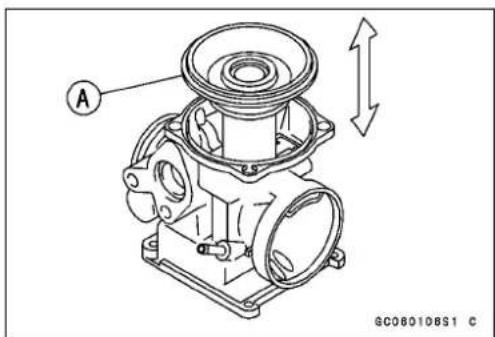
- Disassemblethecarburetor, andcleanthefuel, airpassages with a high-flash-points solvent and compressed air.
- Stuffthelint-free, cleancloths into the aircleanerhousing to keep dirtor other foreign material from entering.
WARNING
Ifdirtordustisallowedtopassthroughintothe carburetor,thethrottlevalvemaystuck,possibly causinganaccident.
AirCleaner
AirCleanerElementRemoval
- Removetheleftsidecover.
-
Removetheelementcover[A]. Front[B]
-
Pullouttheaircleanerelement[A].
- Pushaclean, lint-freetowel into the air cleaner housing to keep dir for other foreign material from entering.
WARNING
Ifdirtordustisallowedtopassthroughintothecar-buretor, thethrottlevalvemaybecomestuck, possiblycausinganaccident.
CAUTION
Ifdirtgetsthroughintotheengine,excessiveenginewearandpossiblyenginedamagewilloccur.
ElementCleaningandInspection
- RefertotheAirCleanerElementCleaningandInspection inthePeriodicMaintenancechapter.
AirCleanerDraining
Acatchtankisprovidedbeneaththeaircleanerhousing, andcatchesthewateroroilfromthebottomofthehousing. Usuallywateroroildoesnotcollectatthebottomofthe housing. Intheeventthatrainwaterisdrawninthroughthe aircleaner, orifengineoilisblownback, drainthehousing.
- Visuallycheckthecatchtank[A]ifthewateroroilaccumulatesinthetank.
★Ifanywateroroilaccumulatesinthetank,drainitby takingoffthedrainplug[B]atthelowerendofthedrain hose. - Installthecatchtankwiththearrow[C]onitpointingupward.
- Besuretoinstalltheplugfirmly.
WARNING
Besuretoinstallthepluginthedrainhoseafterdraining.Oilcoulddrainfromtheopenhoseandgetonthetireswhichcouldcauseanaccidentandinjury.
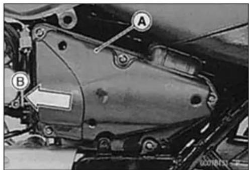
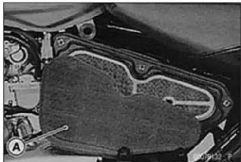
natural_image
Close-up of a mechanical component with labeled parts (A, D) and no visible text or symbols
3-22FUELSYSTEM
AirCleaner
AirCleanerHousingRemoval
- Remove:
SideCoversandSeat(seeFramechapter)
FuelTank(seeFuelTankRemoval)
Battery(seeElectricalSystem)andBatterySeat[A]
BreatherHoseofAirCleaner
StarterRelay[B]
FuseCase[C]
StarterCircuitRelay[D]
HousingMountingBoltsEandScrews[F]
- Removetheelementcover[A]andelement.
- Moveback[B]theaircleanerhousing.
- RemovethecarburetorC.
- Removetheaircleanerhousing[A]fromthevehicle's rightside. Front[B]
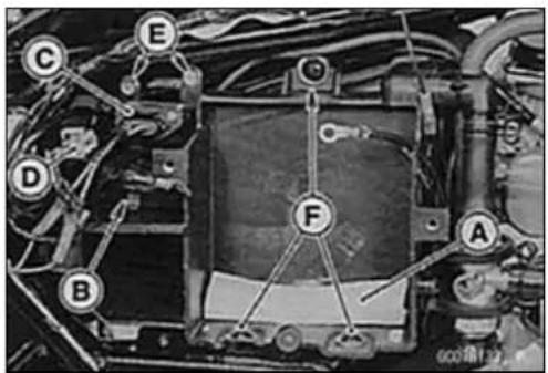


AirCleanerHousingInstallation
- Besuretofittheenginebreatherhoseanddraininghoses intotheaircleanerhousing.
FuelTank
FuelTankRemoval
A WARNING
Gasolineisextremelyflammableandcanbeexplosiveundercertainconditions.Turntheignition switchOFF.Donotsmoke.Makesuretheareais well-ventilatedandfreefromanysourceofflame orsparks;thisincludesanyappliancewithapilot light.
- Removetheseatandsidecovers(seeFramechapter).
- Removethefueltankmountingbolts[A].
- TurnthefueltaptotheOFFForRESposition.
- Pullthehoseoffthetap.

natural_image
Close-up of a high-speed train on tracks with a circular marker labeled 'A' (no visible text or symbols beyond the label)- Disconnecttheindicatorlightleadconnector[A].
- Removethefueltank.
- Drainthefueltank.
○Placeasuitablecontainerunderthefueltank.
○TurnthefueltaptothePRIpositiontodra thecontainer.

FuelTankInstallation
- ReadtheaboveWARNING.
- Checktherubberdampers[A]ontheframe.
★ If the dampers are damaged, deteriorated, replace them. - Routethehoseandleadscorrectly.
- Connecttheindicatorlightconnector.
- Besurethehoseareclampedsecurely.

natural_image
Mechanical assembly diagram showing linkage components and labeled parts (no readable text or symbols)FuelTankInspection
- Removethehosesfromthefueltank, andopenthetank cap.
- Checktoseeifthebreatherpipeandwaterdrainpipein tankarenotclogged.
★ Iftheyareclogged,removethetank anddrainit,andthen blowpipesfreewithcompressedair.
CAUTION
Do not apply compressed air to the air vent holes in thetankcap. This could cause damage and clogging of the labyrinth in the cap.
FuelTank
FuelTankCleaning
WARNING
Cleanthetankinawell-ventilatedarea,andtake carethattherearenosparksorflameanywhere neartheworkingarea.Becauseofthedangerof highlyflammableliquids,donotusegasolineor low-flashpointsolventstocleanthetank.
- Removethefueltankanddrainit.
- Poursomehigh-flashpointsolventintothefueltankand shakethetanktoremovedirtandfueldeposits.
- Pourthesolventoutofthetank.
- Removethefueltapfromthetank(seeFuelTapRemoval).
- Cleanthefueltapfilterscreensinahigh-flashpointsolvent.
- Pourhigh-flashpointsolventthroughthetapinallever positions.
- Drythetankandthefueltapwithcompressedair.
• Installthetapinthetank.
• Installthefueltank.
FuelTapRemoval
- Removethefueltankanddrainit.
- Removethetapbolts[A]withnylonflatwashersandtake outthefueltap.

natural_image
Mechanical assembly diagram showing a linkage mechanism with labeled component A (no readable text or symbols)FuelTapInstallation
- ReplacetheO-rings[A]withanewone.
- Besuretoclampthefuelhosetothetaptopreventleaks.
- Besuretheflatwashers[B]areingoodconditiontopreventleaks.
○Donotusesteelwashersinplaceoftheflatwashers, because they will not seal the bolts properly and fuel will leak. - Tighten:
Torque-FuelTapMountingBolts:
2.5N·m(0.25kgf·m,22in·lb)(WhiteWasher)
4.9N·m(0.50kgf·m,43in·lb)(BlackWasher)

FuelTank
FuelTapInspection
- Removethefueltap.
- Checkthefueltapfilterscreen[A]foranybreaksordeterioration.
★ Ifthefueltapscreenshaveanybreaksoraredeteriorated,theymayallowdirttoreachthecarburetor,causing poorrunning.Replacethefueltap.
★ Ifthefueltapleaks,orallowsfueltoflowwhenitisat OnorRESpositionwithoutenginerunning,replacethe damagedgasket[B]orO-ring[C].
Torque-FuelTapPlateScrews:0.8N·m(0.080kgf·m,7in·lb)
FuelTapDiaphragmCoverScrews:1.0N·m(0.10 kgf·m,9in·lb)

EvaporativeEmissionControlSystem(CaliforniaModelOnly)
The Evaporative Emission Control System routes fuel vapors from the fuels system into other running engine or stores the vapors in a canister when the engine is stopped. Although no adjustments are required, a thorough visual inspection must be made at the interval specified by the Periodic Maintenance Chart.
PartsRemoval/Installation
WARNING
Gasolineisextremelyflammableandcanbeexplosiveundercertainconditions.Turntheignition switchOFF.Donotsmoke.Makesuretheareais well-ventilatedandfreefromanysourceofflame orsparks;thisincludesanyappliancewithapilot light.
CAUTION
If gasoline, solvent, water or any other liquidenters the canister, the canister's vapor absorbing capacity is greatly reduced. If the canister does become contaminated, replace it with anewone.
- Topreventthegasolinefromflowingintooroutofthe canister, holdtheseparatorperpendiculartotheground.
- Connectthehosesaccordingtothediagramofthesystem.Makesuretheydonotgetpinchedorkinked.
- Routehoseswithaminimumofbendingsothattheairor vaporwillnotbeobstructed.
- Besuretoplugthereturnhosetopreventfuelspilling beforefueltankremoval.
WARNING
Whenremovingthefueltank,becarefulnottospill thegasolinethroughthereturnhose.Spilledfuelis hazardous.
★Ifliquidgasolineflowsintothebreatherhose,removethe hoseandblowitcleanwithcompressedair.
HoseInspection
- Check that the hoses are securely connected.
- Replaceanykinked, deterioratedordamaged hoses.
SeparatorInspection
- RefertotheEvaporativeEmissionControlSystem InspectioninthePeriodicMaintenancechapter.
EvaporativeEmissionControlSystem(CaliforniaModelOnly)
SeparatorOperationTest
WARNING
Gasolineisextremelyflammableandcanbeexplosiveundercertainconditions.Turntheignition switchOFF.Donotsmoke.Makesuretheareais well-ventilatedandfreefromanysourceofflame orsparks;thisincludesanyappliancewithapilot light.
- Connectthehosestotheseparator, and install these separatoronthemotorcycle.
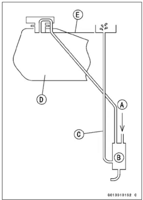
- Disconnectthebreatherhosefromtheseparator, and injectabout20mL(0.68USoz)ofgasoline[A]intotheseparator[B]throughthehosefitting.
- Disconnectthefuelreturnhose[C]fromthefueltank[D].
- Placetheopenendofthereturnhoseintothecontainer andholditwiththesamelevelofthetanktopE.
- Starttheengine, and letitidle.
★ Ifthegasolineintheseparatorcomesoutofthehose,the separatorworkswell.Ifitdoesnot,replacetheseparator withanewone.
CanisterInspection
- RefertotheEvaporativeEmissionControlSystemInspectioninthePeriodicMaintenancechapter.
EngineTopEnd
TableofContents
ExplodedView....4-2
Specifications....4-6
SpecialTools....4-9
CleanAirSystem(ForAT,CH,DEof BN125-A1\~A2andotherthanthe CAL)....4-11
AirSuctionValveInstallation......4-11
AirSuctionValveInspection......4-11
VacuumSwitchValveRemoval...4-11
VacuumSwitchValveInstallation 4-11
VacuumSwitchValveUnitTest.... 4-12
CleanAirSystemHose Inspection.... 4-12
CleanAirSystem(CaliforniaModel). 4-13
VacuumSwitchValveTest 4-13
CamshaftChainTensioner 4-14
Camshaft Chain Tensioner Removal.... 4-14
Camshaft Chain Tensioner Installation.... 4-14
Camshaft 4-16
CamshaftRemoval.... 4-16
CamshaftInstallation.... 4-17
CamshaftChainRemoval...... 4-18
CamshaftChainInstallation...... 4-19
CylinderHead 4-21
CylinderCompression Measurement 4-21
CylinderHeadRemoval 4-22
CylinderHeadInstallation 4-23
CylinderHeadAssembly.... 4-24
CylinderHeadCleaning 4-24
CylinderHeadWarp 4-25
Valves 4-26
ValveClearanceInspection...... 4-26
ValveClearanceAdjustment...... 4-26
Valve Removal 4-26
ValveInstallation 4-26
ValveGuideRemoval.... 4-26
ValveGuideInstallation.... 4-27
Valve-to-Guide Clearance Measurement(Wobble Method).... 4-27
ValveSeatInspection...... 4-28
ValveSeatRepair.... 4-28
Cylinder, Piston.... 4-33
CylinderRemoval.... 4-33
PistonRemoval.... 4-33
Cylinder,PistonInstallation...... 4-33
CylinderWear 4-35
PistonWear.... 4-35
Piston/CylinderClearance...... 4-36
PistonRing, PistonRingGroove Wear.... 4-36
PistonRingGrooveWidth.... 4-36
PistonRingThickness.... 4-37
PistonRingEndGap.... 4-37
CarburetorHolder 4-38
CarburetorHolderInstallation ..... 4-38
Muffler.... 4-39
MufflerRemoval 4-39
MufflerInstallation 4-39

ExplodedView
| No. | Fastener | Torque | Remarks | ||
| N·mkgf | ·mft·lb | ||||
| 1 | Valve Adjusting Cap Bolts (BN125-A1 ~ A3) | 9.8 | 1.0 | 87 in·lb | |
| Valve Adjusting Cap Bolts (BN125-A4 ~) | 8.8 | 0.90 | 78 in·lb | ||
| 2 | CamshaftChainCoverBolts(BN125-A1~ A3) | 9.81.08 | 7in·lb | ||
| Camshaft Chain Cover Bolts (BN125-A4 ~) | 8.8 | 0.90 | 78 in·lb | ||
| 3 | Cylinder Head Bolts (M9) | 26 | 2.7 | 19 | S, M |
| 4 | Cylinder Head Bolts (M6) | 12 | 1.2 | 104 in·lb | S |
| 5 | Spark Plug | 13 | 1.3 | 9.5 | |
| 6 | CamshaftChainCoverDamperBolts(BN125-A1 ~ A3) | 9.81.08 | 7in·lb | ||
| CamshaftChainCoverDamperBolts(BN125-A4 ~) | 8.80.90 | 78in·lb | |||
| 7 | CarburetorHolderBolts | 9.81.08 | 7in·lb | ||
| 8 | Air Suction Valve Cover Bolts (BN125-A1 ~ A3) | 9.8 | 1.0 | 87 in·lb | |
| Air Suction Valve Cover Bolts (BN125-A4 ~) | 8.8 | 0.90 | 78 in·lb | ||
| 9 | Cylinder Head Blank Cap Bolts (BN125-A1 ~ A3) | 9.81.08 | 7in·lb | ||
| Cylinder Head Blank Cap Bolts (BN125-A4 ~) | 8.8 | 0.90 | 78 in·lb | ||
| 10 | Vacuum Switch Valve Pipe Mounting Bolts | 8.8 | 0.90 | 78 in·lb | |
| 11 | Vacuum Hose Fitting | 5.9 | 0.60 | 52 in·lb | |
| 12 | Oil Pipe Banjo Bolt (M10) | 25 | 2.5 | 18 | |
| 13 | Oil Pipe Banjo Bolts (M8) | 9.8 | 1.0 | 87 in·lb | |
| 14 | Oil Pipe Mounting Bolts (BN125-A1 ~ A3) | 9.8 | 1.0 | 87 in·lb | |
| Oil Pipe Mounting Bolts (BN125-A4 ~) | 8.8 | 0.90 | 78 in·lb | ||
15."R"markedsidefacesup.
16."RN"markedsidefacesup.
17. Air suction valve (For AT, CH, DE of BN125-A1 \~ A2 and other than the CAL of BN125A3 \~)
18. Other than AT, CH, DE of among the BN125-A1 \~ A2)
19. CaliforniaModel
EO: Applyengineoil.
G: Applygrease.
L: Applyanon-permanentlockingagent.
M: Applymolybdenumdisulfidegrease.
MO: Apply molybdenum disulfide oil. The molybdenum disulfide oil is a mixture of engine oil and molybdenumdisulfidegreasewithaweightratio(10:1).
R: ReplacementParts
S: Followthespecifictighteningsequence.
AT: Austria
CAL: California
CH: Switzerland
DE: Germany
ExplodedView

ExplodedView
| No. | Fastener | Torque | Remarks | ||
| N·mkgf | ·mft·lb | ||||
| 1 | Camshaft Bearing Holder Bolts (BN125-A1 ~ A3) | 9.8 | 1.0 | 87 in·lb | |
| Camshaft Bearing Holder Bolts (BN125-A4 ~) | 8.8 | 0.90 | 78 in·lb | ||
| 2 | CamshaftSprocketBolts | 12 | 1.2104 | in·lb | |
| 3 | Camshaft Chain Holder Screw | 4.9 | 0.50 | 43 in·lb | |
| 4 | Camshaft Chain Guide Bolt | 8.8 | 0.90 | 78 in·lb | |
| 5 | Chain Tensioner Mounting Bolts (BN125-A1 ~ A3) | 9.8 | 1.0 | 87 in·lb | |
| Chain Tensioner Mounting Bolts (BN125-A4 ~) | 8.8 | 0.90 | 78 in·lb | ||
| 6 | Chain Tensioner Cap | 4.9 | 0.50 | 43 in·lb | |
| 7 | ValveAdjustingScrewLocknut | 15 | 1.5 | 11 | |
| 8 | Rocker Shaft Bolts | 8.8 | 0.90 | 78 in·lb | |
| 9 | Muffler Body Mounting Nut | 15 | 1.5 | 11 | |
M: Apply molybdenum disulfide grease.
MO: Apply molybdenum disulfide oil. The molybdenum disulfide oil is a mixture of engine oil and molybdenumdisulfidegreasewithaweightratio(10: 1).
R: Replacementparts
Specifications
| ItemStandardServiceLimit | ||
| CleanAirSytemVacuumSwitchValveClosingPressure:(AT,CH,DE,oftheBN125-A1~A2andothethantheCAL)(CAL) | Open→ Close--45 ~ 53 kPa (340 ~ 400 mmHg, 6.5 ~ 7.7 psi)41 ~ 52 kPa (310 ~ 390 mmHg, 6.0 ~ 7.5 psi) | --- |
| CamshaftCamHeight:ExhaustInletCamshaft RunoutRocker Arm Inside diameterRocker Shaft Diameter | 39.348~ 39.464mm( 1.5491~ 1.5537in.)39.707 ~ 39.823 mm (1.5633 ~ 1.5678 in.)TIR 0.02 mm (0.0008 in.) or less13.000 ~ 13.018 mm (0.5118 ~ 0.5125 in.)12.983 ~ 12.994 mm (0.5111 ~ 0.5116 in.) | 39.25mm(1.545in.)39.61 mm (1.559 in.)TIR 0.1 mm (0.004 in.)13.05 mm (0.514 in.)12.96 mm (0.510 in.) |
| CylinderHeadCylinderCompressionCylinderHead Warp | (Usablerange)960 ~ 1 470 kPa (9.8 ~ 15.0 kgf/cm2, 139 ~ 213psi)@500r/min(rpm)-- -- | ---0.05mm(0.002 in.) |
| ValvesValveClearance:ExhaustInletValveHeadThickness:ExhaustInletValve Stem BendValveStemDiameter:ExhaustInletValveGuideInsideDiameter:ExhaustInletValve/valveGuideClearance(WobbleMethod):ExhaustInletValveSeatCuttingAngleValveSeatSurfaceOutsideDiameter:ExhaustInlet | 0.15 ~ 0.19 mm (0.006 ~ 0.007 in.)0.08 ~ 0.12 mm (0.003 ~ 0.005 in.)0.9 ~ 1.1 mm (0.035 ~ 0.043 in.)0.6 ~ 0.8 mm (0.024 ~ 0.031 in.)TIR 0.01 mm (0.0004 in.) or less4.455 ~ 4.470 mm (0.1754 ~ 0.1760 in.)4.475 ~ 4.490 mm (0.1762 ~ 0.1768 in.)4.500 ~ 4.512 mm (0.1772 ~ 0.1776 in.)4.500 ~ 4.512mm(0.1772~ 0.1776in.)0.14 ~ 0.19 mm (0.006 ~ 0.007 in.)0.03 ~ 0.13 mm (0.001 ~ 0.005 in.)45°,32°,60° | ---0.5 mm (0.02 in.)0.4 mm (0.01 in.)TIR0.05mm(0.002in.)4.44 mm (0.175 in.)4.46 mm (0.176 in.)4.57 mm (0.180 in.)4.57mm(0.1 80in.)0.38 mm (0.015 in.)0.33 mm (0.013 in.)--- |
Specifications
| ItemStandardServiceLimit | ||
| Width: | ||
| Exhaust | 0.8~1.2mm(0.03~0.05in.) | -- -- |
| Inlet | 0.8~1.2mm(0.03~0.05in.) | -- -- |
| ValveSpringFreeLength: | ||
| Exhaust | 43.51mm(1.713in.)42.1mm(1.66in.) | |
| Inlet43.51mm(1.713in.)42.1mm(1.66in.) | ||
| Cylinder,Piston | ||
| Cylinder Inside Diameter | 55.000 ~ 55.012 mm (2.1654 ~ 2.1658 in.) | 55.10 mm (2.169 in.) |
| Piston Diameter | 54.960 ~ 54.975 mm (2.1638 ~ 2.1644 in.) | 54.81 mm (2.158 in.) |
| 54.968 ~ 54.982 mm (2.1641 ~ 2.1646 in.) | 54.82 mm (2.158 in.) | |
| (BN125-A7~, N , N U) | ||
| Piston/cylinder Clearance | 0.025 ~ 0.052 mm (0.0010 ~ 0.0020 in.) | -- -- |
| 0.0241 ~ 0.0385 mm (0.0009 ~ 0.0015 in.) | ||
| (BN125-A7~, N , NU ) | ||
| OversizePistonandRings | +0.5mm(0.02in.),+1.0mm(0.04in.) | -- -- |
| Piston Ring/groove | ||
| Clearance: | ||
| Top | 0.03 ~ 0.07 mm (0.0012 ~ 0.0028 in.) | 0.17 mm (0.0067 in.) |
| Second | 0.02 ~ 0.06 mm (0.0008 ~ 0.0024 in.) | 0.16 mm (0.0063 in.) |
| PistonRingGrooveWidth: | ||
| Top | 0.82 ~ 0.84 mm (0.0323 ~ 0.0331 in.) | 0.92 mm (0.0362 in.) |
| Second | 0.81 ~ 0.83 mm (0.0319 ~ 0.0327 in.) | 0.91 mm (0.0358 in.) |
| PistonRingThickness: | ||
| Top | 0.77 ~ 0.79 mm (0.0303 ~ 0.0311 in.) | 0.70 mm (0.028 in.) |
| Second | 0.77 ~ 0.79 mm (0.0303 ~ 0.0311 in.) | 0.70 mm (0.028 in.) |
| PistonRingEndGap: | ||
| Top | 0.15 ~ 0.30 mm (0.006 ~ 0.012 in.) | 0.60 mm (0.024 in.) |
| Second | 0.30 ~ 0.45 mm (0.012 ~ 0.018 in.) | 0.70 mm (0.028 in.) |
| Oil | 0.20 ~ 0.70 mm (0.008 ~ 0.028 in.) | 1.0 mm (0.04 in.) |
AT: Austria
CAL:California
CH:Switzerland
DE:Germany
N: No Catalytic Converter Model
NU:NoCatalyticConverter(UnitedKingdom
Model)
4-8ENGINETOPEND
Specifications
CamHeight
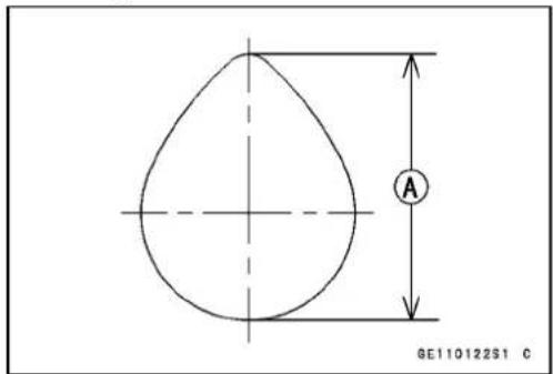
CamHeight[A]
ValveHeadThickness

ValveStemDiameter[A]
ValveHeadThickness[B]
45^[C]
CamshaftRunout

natural_image
Technical line drawing of a mechanical assembly with a pressure gauge and shaft (no text or symbols)ValveStemBend

DialGauge[A]
SpecialTools
CompressionGauge,20kgf/cm²: 57001-221

natural_image
Technical line drawing of a pressure gauge with no text or symbolsValveSpringCompressorAssembly: 57001-241
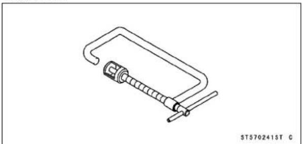
natural_image
Line drawing of a mechanical clamp or spring-loaded tool with no text or symbolsPistonPinPullerAssembly: 57001-910
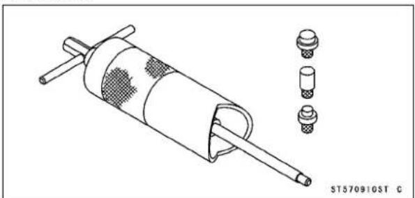
natural_image
Technical line drawing of a mechanical component with multiple bolted and cylindrical features (no text or symbols)ValveSeatCutter,45°-27φ5:57001-1114

natural_image
Simple line drawing of a cylindrical object with a textured top and central hole, no text or symbols present.ValveSeatCutter,45°-32:φ
57001-1115

natural_image
Isometric line drawing of a cylindrical object with concentric rings and textured top surface (no text or symbols)ValveSeatCutter,32°-30φ
57001-1120
natural_image
Simple line drawing of a cylindrical object with a textured top and central hole, labeled 'ST571120ST C' at bottom (no other text or symbols)ValveSeatCutter,32°-35:φ
57001-1121

natural_image
Isometric line drawing of a cylindrical object with concentric rings and textured top surface (no text or symbols)ValveSeatCutter,60°-30φ
57001-1123

natural_image
Line drawing of a conical object with a circular top and textured base, labeled 'ST571123ST C' at bottom (no other text or symbols)ValveSeatCutterHolderBar: 57001-1128
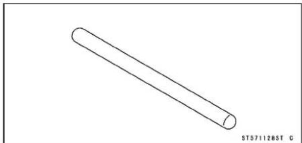
natural_image
Simple line drawing of a cylindrical object with no text or symbolsValveSpringCompressorAdapter,22φ 57001-1202
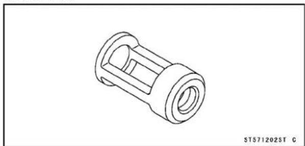
natural_image
Technical line drawing of a mechanical component (no text or symbols)SpecialTools
ForkOilLevelGauge: 57001-1290

natural_image
Technical line drawing of mechanical components including a cylindrical spring and a threaded rod (no text or symbols)CompressionGaugeAdapter, M10×1.0: 57001-1317

natural_image
Line drawing of a U-shaped mechanical component with two connectors and a shaft (no text or symbols)ValveSeatCutterHolder,4.5p
57001-1330

natural_image
Line drawing of a cylindrical electronic component with a short shaft and end cap (no text or symbols)ValveGuideArbor,4.5: 57001-1331

natural_image
Line drawing of a mechanical tool or rod with textured end and shaft (no text or symbols)ValveGuideReamer,4.51
57001-1333

natural_image
Technical line drawing of a mechanical tool or rod with flanged ends and a tapered shaft (no text or symbols)ValveSeatCutter,60°-33: 57001-1334
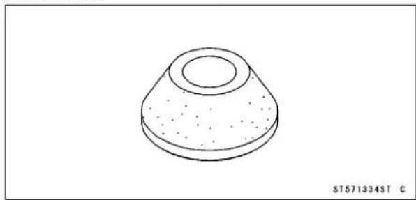
natural_image
Isometric line drawing of a conical object with a circular top and textured base (no text or symbols)○ValveSeatCutter,32°-33φ57001-1199can alsobeusedinsteadofValveSeatCutter, 32°-φ35:57001-1121
○ValveSeatCutter,45°-30φ57001-1187can alsobeusedinsteadofValveSeatCutter, 45°-φ27.5:57001-1114
Clean Air System (For AT, CH, DE of BN125-A1 \~ A2 and other than the CAL)
AT:Austria
CAL:California
CH:Switzerland
DE:Germany
AirSuctionValveInstallation
- Installtheairsuctionvalvesothatitsnumber[A]ofthe readfacesoutsideanddownward.
- Tighten:
Torque-AirSuctionValveCoverBolts:
(BN125-A1\~A3):9.8N·m(1.0kgf·m,87in·lb)
(BN125-A4 \~): 8.8 N·m (0.90 kgf·m, 78 in·lb)

natural_image
Close-up of a hand adjusting a mechanical component with a labeled part (A) and '6LDS' logo, no readable text or symbols beyond the label.AirSuctionValveInspection
- RefertotheAirSuctionValveInspectioninthePeriodic Maintenancechapter.
VacuumSwitchValveRemoval
- Removetherightsidecover(seeFramechapter).
- Removethehose[A]fromtheaircleanerhousing.
- Pullthedamper[B]upwardtocleanerthestopper[C].
- Remove:
Pipe[D]
VacuumHose
VacuumSwitchValveE
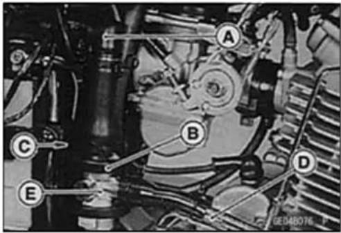
VacuumSwitchValveInstallation
- InstallthehoseAsothatthemark [B]onitfacesupward.
- Alignthevacuumpipe[C], thearrowmark[D] on the damperE, andthemark[F] on the airhose[G] (toair cleaner).
Clamps[H]
VacuumSwitchValve[l]
Facethetabs[J]asshown.
- Routethehosescorrectly(seeAppendixchapter).

Clean Air System (For AT, CH, DE of BN125-A1 \~ A2 and other than the CAL)
VacuumSwitchValveUnitTest
- Removethevacuumswitchvalve(seeVacuumSwitchValveRemoval).
- Connectacommerciallyavailablevacuumgauge[A]and syringeBtothevacuumhoses asshown.
SpecialTool-ForkOilLevelGauge:57001-1290
AirFlow[C]
- Graduallyraisethevacuum(lowerthepressure)applied tothevacuumswitchvalve,andcheckthevalveoperation.Whenthevacuumislow,thevacuumswitchvalve shouldpermitairtoflow.Whenthevacuumraisesto valveclosingpressure,itshouldstopairflow.
★Ifthevacuumswitchvalvedoesnotoperateasdescribed, replaceitwithanewone.
NOTE
○ Tocheckairflowthroughthevacuumswitchvalve, just blowthroughtheaircleanerhose.
VacuumSwitchValveClosingPressure(Open→ Close) Standard: 45 \~ 53 kPa (340 \~ 400mmHg, 6.5 \~ 7.7 psi)


CleanAirSystemHoseInspection
- Be certain that all the hoses are routed without being flattenedorkinked, and are connected correctly to the rightaircleanerhousing, vacuumswitchvalve, carburetorholder, and airsuctionvalvecovers.
★Iftheyarenot,correctthem. Replacethemiftheyare damaged.
CleanAirSystem(CaliforniaModel)
VacuumSwitchValveTest
- Removethevacuumswitchvalve.
- Connectthevacuumgauge[A]andsyringe[B]orforkoil levelgaugetothevacuumhosesasshown.
SpecialTool-ForkOilLevelGauge:57001-1290
AirFlow[C]
- Graduallyraisethevacuum(lowerthepressure)applied tothevacuumswitchvalve,andcheckthevalveoperation.Whenthevacuumislow,thevacuumswitchvalve shouldpermitairtoflow.Whenthevacuumraisesto valveclosingpressure,itshouldstopairflow.
Spring[A]
Diaphragm[B]
Valve[C]
LowVacuum[D]
SecondaryAirFlowE
HighVacuum[F]
SecondaryAirFlowCannotFlow[G]
★ If the vacuum switch valved does not operate as described, replace it with anewone.
NOTE
○Tocheckairflowthroughthevacuumswitchvalve,just blowthroughtheaircleanerhose.
VacuumSwitchValveClosingPressure(Open→ Close)
Standard: 41 \~ 52 kPa (310 \~ 390 mmHg)


CamshaftChainTensioner
CamshaftChain TensionerRemoval
CAUTION
Thisisanon-returntypecamchaintensioner. The pushroddoesnotreturntoitsoriginalposition onceitmovesouttotakeupcamshaftchainslack. Observealltheruleslistedbelow: When removing the tensioner, donottakeoutthemountingbolts onlyhalfway. Retighteningthemountingbolts from this position could damage the tensioner and the camshaftchain. Oncetheboltsareloosened, the tensioner must be removed and reset as described in "CamshaftChain Tensioner Installation." Donot turnover the crankshaft while the tensioner is removed. This could upset the camchaintiming, and damage the valves.
- Removethechaintensionercap[A]togetherwithO-ring.
- Removethemountingbolts[B]andtakeoffthecamshaft chaintensioner.

natural_image
Close-up of mechanical components with labeled parts A and B, no readable text or symbols beyond labelsCamshaftChainTensionerInstallation
- Whilecompressingthepushrod[A],turn[C]itclockwise withasuitablescrewdriver[B]untiltherodstops.
CAUTION
Donotturntherodcounterclockwiseatinstallation. Thiscoulddetachtherodandthetensionercannot bereinstalled.
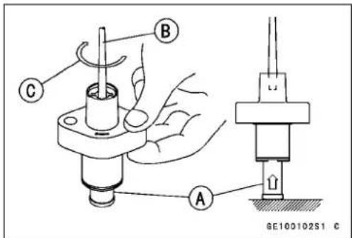
- Whileholdingtherodinpositionwiththescrewdriverora holderplate[A],installthetensioneronthecylinderblock.
NOTE
○ Tomaketheprocedureeasy, useaholderplatetokeep therodfrompushingout. Areplacementchaintensioner(spareparts) hasaholderplate.
- Theholderplatecanbemadeof1mm(0.04in.) thick aluminumplateasshown.

CamshaftChainTensioner
• InstalltheO-ringinthetensionerbody.
- Installthetensionersothatthearrowmark[B]facesupward,andtightenthemountingbolts.
Torque-ChainTensionerMountingBolts
(BN125-A1 \~ A3): 9.8 N·m (1.0 kgf·m 87in·lb)
(BN125-A4 \~): 8.8 N·m (0.90 kgf·m 87in·lb)
- Removethescrewdriver(ortheholderplate[A])and tightenthecap.
Torque-ChainTensionerCap:4.9N·m(0.50kgf·m,43in·lb)

4-16ENGINETOPEND
Camshaft
CamshaftRemoval
- Remove:
FuelTankA
CamshaftChainCover[B]
ValveAdjustingCaps[C]
- Holdingthecamshaftcenterbolt[A]withawrench,loosen thecamshaftsprocketbolts[B].
- Turnthecamshaftcenterbolt[A]clockwisesothatthe mark[B]onthesprocketalignswiththetimingmark [C]onthecylinderhead.Besuretopositionthepiston TDCattheendofthecompressionstrokebyturningthe camshaft.(Alignthemarkwhentheinletvalveagain comesupafteritwentdownonce.)
- Remove:
CamshaftChainTensioner(seethischapter) CamshaftSprocket[A]
NOTE
○ Holdthecamshaftchainwithsometoolsothatthechain doesnotfallintotheengine.
- Remove:
IgnitionCoil[A]
LeftCylinderHeadBolts[B]
RockerShaftBolts[C]
○Discardtherockershaftboltwashers.

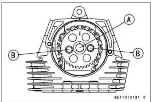
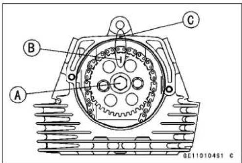

natural_image
Close-up of hands assembling a mechanical component with no visible text or symbols
Camshaft
- UsingascrewA,removetherocker shafts[B].
○ Marktherockershaftssothattheycanbeinstalledlater inthesameposition.
- Remove: RockerArms[A] CamshaftBearingHolder[B]
○ Marktherockerarmssothattheycanbeinstalledlaterin thesameposition.
- Pulloutthecamshaft[A].
CAUTION
Thecrankshaftmaybeturnedwhilethecamshaftis removed.Alwayspullthechaintautwhileturning thecrankshaft.Thisavoidskinkingthechainonthe lower(crankshaft)sprocket.Akinkedchaincould damageboththechainandthesprocket.
CamshaftInstallation
- Blowthroughtheoilpassage[B]withcompressedair[A].
- Applyengineoiltoallcamparts, journalandbearing.
○ Ifthecamshaftisreplacedwithanewone,applyathin coatofmolybdenumdisulfidegreasetothenewcampart surfacesandjournal.
- Installthecamshaftwiththecamportion[A]downandthe hole[B]up.
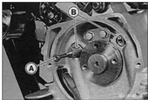
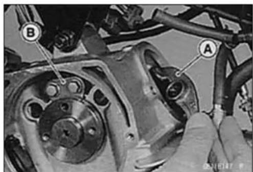
natural_image
Close-up of mechanical components with labeled parts A and B, showing wiring and assembly (no readable text or symbols)
natural_image
Close-up of a mechanical assembly with a hand holding a component, no visible text or symbols
4-18ENGINETOPEND
Camshaft
- Installthecamshaftbearingholder[A]. - Applyengineoiltotherockershaftsurfaceandcamportionoftherockerarm,andtheninstallthemattheoriginal position.
○Installtherockershafts[B]sothatthescrewthreadsface outward.
- Replacetherockershaftboltwasherswithnewones.
- Install: CylinderHeadBolts(seeCylinderHeadInstallation) RockerShaftBolts
- Tighten: Torque-CamshaftBearingHolderBolts (BN125-A1 \~ A3): 9.8 N·m (1.0 kgf·m, 87 in·lb) (BN125-A4\~): 8.8N·m (0.90kgf·m, 78in·lb) RockerShaftBolts: 8.8N·m (0.90kgf·m, 78in·lb)
- Engagethecamshaftsprocket[A]withthechain[B]. Then, alignthe"T"mark[C]onthesprocketwiththe timingmark[D]onthecylinderhead.
NOTE
○ Pullthetensionside(exhaustside)ofthechainupto removeslack.
Torque-CamshaftSprocketBolts:12N·m(1.2kgf·m,104in·lb)
- Installthecamshaftchaintensioner(seeCamshaftChain TensionerInstallation).
- Checkthevalveclearance(seePeriodicMaintenance chapter).
- Tighten: Torque-CamshaftChainCoverBolts (BN125-A1 \~ A3): 9.8 N·m (1.0 kgf·m, 87 in·lb) (BN125-A4\~):8.8N·m(0.90kgf·m,78in·lb)
CamshaftChainRemoval
- Remove: CamshaftSprocketA Alternator(seeElectricalSystemchapter)
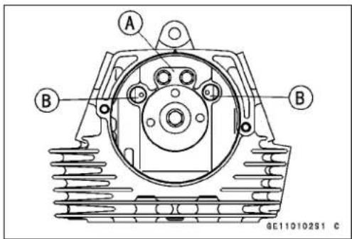
natural_image
Close-up of a mechanical assembly with hands adjusting components (no visible text or symbols)Camshaft
-
Removethecrankbalancergear[A].
SpecialTool-OutsideCirclipPliers:57001-144
○ Stuffacleanclothintothehole[B]sothatthebalancer damperspringswillnotfallintoit. -
Removethecamshaftchainholder[A], and pull the camshaftchain[B] upward.
- Removethecylinderhead(seeCylinderHeadRemoval).
- Removetherearcamshaftchainguidebolt[C], and pull therearcamshaftchainguide[D].

natural_image
Mechanical gear assembly diagram showing two meshed gears with labeled points A and B (no text or symbols beyond labels)
CamshaftChainInstallation
- Install: RearCamshaftChainGuide[A] CylinderHead(seeCylinderHeadInstallation)
- Tighten: Torque-CamshaftChainGuideBolt:8.8N·m(0.90kgf·m, 78in·lb)
- Engagethecamshaftchain[B]withthecranksprocket, andinstallthecamshaftchainholder[C].
- Tighten: Torque-CamshaftChainHolderscrews:4.9N·m(0.50 kgf·m,43in·lb)
○ Pullthecamshaftchainandtietheupperendofthechain withacordsothatthechainisnotkinking.
- Installtheinnerandoutersprings[B]intothegroovenear thepunchmark[A]onthecrankbalancergear, and install thefivespringsandpins[C]intotheothergrooves.
○Theinnerandouterspringsarealittlelongerthanthefive identicalsprings.


4-20ENGINETOPEND
Camshaft
○Alignthethreepunchmarks[D]onthebalancershaftgear [A],crankbalancergear[B],andcoupling[C].
• Installthealternator(seeElectricalSystemchapter).
- Alignthepunchmark[A]onthecrankcasewiththe“T” mark[B]ontherotor.
- Engagethecamshaftsprocket[A]withthechain[B]. Then alignthe"T"mark[C]onthesprocketwiththetimingmark[D]onthecylinderhead.
NOTE
○ Pullthetensionside(exhaustside)ofthechainupto removeslack.
- Tighten:
Torque-CamshaftSprocketBolts:12N·m(1.2kgf·m,104in·lb)
- Install:
CamshaftChaintensioner(seeCamshaftChainTensionerInstallation)
AlternatorRotor(seeElectricalSystemchapter)
AlternatorCover(seeElectricalSystemchapter)
CamshaftChainCover
- Tighten:
Torque-CamshaftChainCoverBolts
(BN125-A1 \~ A3): 9.8 N·m (1.0 kgf·m, 87 in·lb)
(BN125-A4\~):8.8N·m(0.90kgf·m,78in·lb)


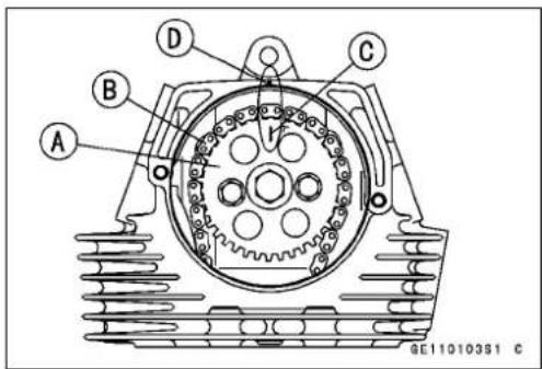
CylinderHead
CylinderCompressionMeasurement
NOTE
○Usethebatterywhichisfullycharged
- Warmuptheenginethoroughly.
- Stoptheengine.
- Remove:
FuelTank(seeFuelSystemchapter) SparkPlug
Owner's Tool-SparkPlugWrench, Hex16:92110-1172[A]
- Attachthecompressiongauge[A]andadapter[B]firmly intothesparkplughole.
SpecialTools-CompressionGauge,20kgf/cm²:57001-221 CompressionGaugeAdapter,M10×1.0: 57001-1317
- Usingthestartermotor, turntheengineoverwiththethrottlefullyopenuntilthecompressiongaugestopsrising; the compressionisthehighestreadingobtainable.
CylinderCompression
UsableRange: 960 \~ 1 470 kPa (9.8 \~ 15.0 kgf/cm², 139
\~ 213psi)@500r/min(rpm)
• Installthesparkplugandtightenit.
Torque-SparkPlug:13N·m(1.3kgf·m,113in·lb)

natural_image
Close-up of a hand using a tool to adjust or install an engine component (no visible text or symbols)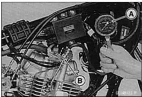
The following tables should be consulted if the obtainable compression reading is not within the usability range.
| ProblemDiagnosis | Remedy(Action) | |
| Cylinder compression ishigherthan usablerange | Carbonaccumulationonpistonandin combustionchamberpossiblydueto damagedvalvestemoilsealand/or damagedpistonoilrings(Thismaybe indicatedbywhiteexhaustsmoke). | Removethecarbo ndepositsandreplace damagedpartsifnecessary. |
| Incorrectcylinderheadgasket thickness. | Replacethegasketwithastandardpart. | |
| Cylinder compression islowerthan usablerange | Gasleakagearoundcylinderhead | Replacedamagedgasketandcheck cylinderheadwarp. |
| Badconditionofvalveseating | Repairifnecessary. | |
| Incorrectvalveclearance. | Adjustthevalveclearance. | |
| Incorrectpiston/cylinderclearance | Replacethepistonand/orcylinder | |
| Pistonseizure. | Inspectthecylinder(andliner)and replace/repairthecylinderand/orpiston asnecessary. | |
| Badconditionofpistonringand/or pistonringgrooves | Replacethepistonand/orthepistonrings. |
4-22ENGINETOPEND
CylinderHead
CylinderHeadRemoval
- Remove:
FuelTank(seeFuelSystemchapter) ExhaustPipeA CarburetorB OilPipeC SparkPlugCap IgnitionCoil CDIUnit(seeElectricalSystemchapter)
- Remove:
EngineUpperBracket[A] CamshaftChainCover[B]
- Removethecamshaftsprocketfromthecamshaftchain (seeCamshaftRemoval).
- Remove:
6mmCylinderHeadBolts[A] 9mmCylinderHeadBolts[B] Front[C]
- Removethe9mmcylinderheadbolt[A]attherearright alongwiththecylinderhead. Front[B]
NOTE
○ Ifnecessarytaplightlywithaplastichammerasshown. Nevertaponthefins.
- Clearthechainguides[B], andremovethecylinderhead [A].
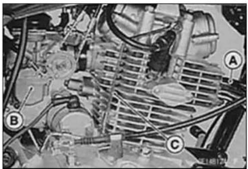
natural_image
Close-up of an automotive engine bay with labeled components (A, B, C), no visible text or symbols beyond labels.


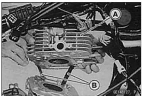
CylinderHead
CylinderHeadInstallation
- Install:
DowelPins[A]
NewCylinderHeadGasket[B]
- Applymolybdenumdisulfidegreasetothethreadsofthe 9mmcylinderheadbolts[1\~4], andengineoiltoboth sidesofthewashers.
- Tightenthe9mmboltsfollowingthetighteningsequence asshown. Tightenthemfirsttothetorqueof12N·m(1.2 kgf·m, 104in·lb), andthentightenthemtothespecified torque.
Torque-9mmCylinderHeadBolts:26N·m(2.7kgf·m,19ft·lb)
- Tightenthe6mmbolts[5\~6].
Torque-6mmCylinderHeadBolts:12N·m(1.2kgf·m,104in·lb)
- Install:
CamshaftSprocket(seeCamshaftInstallation)
CamshaftChainTensioner(seeCamshaftChainTensionerInstallation)
ValveAdjustingCaps
- ApplygreasetotheO-ring, and install the camshaft chain cover.
- Tighten:
Torque-CamshaftChainCoverBolts
(BN125-A1\~A3):9.8N·m(1.0kgf·m,87in·lb)
(BN125-A4 \~): 8.8 N·m (0.90 kgf·m, 78 in·lb)
OilPipeBanjoBolts[A]
(M10):25N·m(2.5kgf·m,18ft·lb)
(M8):9.8N·m(1.0kgf·m,87in·lb)
OilPipeMountingBolts[B]
(BN125-A1\~A3):9.8N·m(1.0kgf·m,87in·lb)
(BN125-A4 \~): 8.8 N·m (0.90 kgf·m, 78 in·lb)
CylinderHeadMountingBolts:25N·m(2.5kgf·m, 18in·lb)
- Install:
Carburetor(seeFuelSystemchapter)
Exhaustpipe(seeMufflerRemoval)
FuelTank(seeFuelSystemchapter)

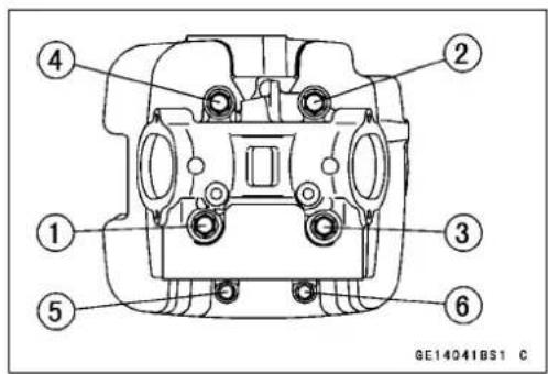
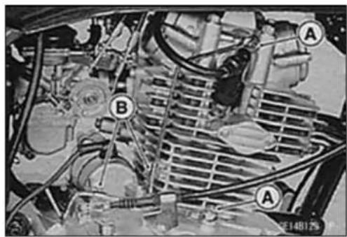
CylinderHead
CylinderHeadAssembly
• Installtherubberdampersasshown.
Dampers[A]
Fins[B]
Front[C]

CylinderHeadCleaning
- Removethecylinderhead(seeCylinderHeadRemoval).
- Removethevalves(seeValveRemoval).
- Washtheheadwithahigh-flashpointsolvent.
- Scrapethecarbonoutofthecombustionchamberand exhaustportwithasuitabletool.
- Cleanthecylinderheadinabathofhigh-flashpointsolvent.
- Usingcompressedair, blowout[A]anyparticles which may obstruct the oil passage in the cylinder head.
• Installthevalves(seeValveInstallation).
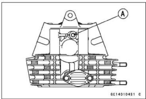
CylinderHead
CylinderHeadWarp
- Cleanthecylinderhead(seeCylinderHeadCleaning).
- Layastraightedgeacrossthelowersurfaceofthecylinder headatthepositionsasshown.
- Useathicknessgauge[A]tomeasurethespacebetween thestraightedge[B]andthecylinderhead.
CylinderHeadWarp
Standard: ---
ServiceLimit:0.05mm(0.002in.)
★ Ifthecylinderheadiswarpedmorethantheservicelimit, replaceit.
★ Ifthecylinderheadiswarpedlessthantheservicelimit, repairtheheadbyrubbingthelowersurfaceonemery papersecuredtoasurfaceplate(firstNo.200, thenNo.400).

Valves
ValveClearanceInspection
- RefertotheValveClearanceInspectioninthePeriodic Maintenancechapter.
ValveClearanceAdjustment
- RefertotheValveClearanceAdjustmentinthePeriodic Maintenancechapter.
ValveRemoval
- Removethecylinderhead(seeCylinderHeadRemoval).
- Removetherockershaftsandrockerarms(seeCamshaft Removal).
○Markandrecordtherockershafts, rockerarms, and valveslocationssothattheycanbeinstalledintheiroriginalpositionstokeepthevalveclearanceunchanged.
- Using the valvespringcompressorassembly, remove the valves.
SpecialTools-ValveSpringCompressorAssembly:57001-241[A]
ValveSpringCompressorAdapter, 57001-1202[B] 22

ValveInstallation
- Replacetheoilseal[C]withanewone.
- Applyathincoatofmolybdenumdisulfidegreasetothe valvestem[A]beforevalveinstallation.
- Checkthefollowing: Valvemovesssmoothlyupanddownintheguide. Valveseatsproperlyinthevalveseat.
- Installthespring[D]sothattheclosedcoilendfacesthe springseatB.
- PutthespringretainerEonthesprings, and fitthesplit keepers[F] between theretainer and the stem while compressing the valvespring.
SpecialTools-ValveSpringCompressorAssembly:57001-241
ValveSpringCompressorAdapter, 22: 57001-1202
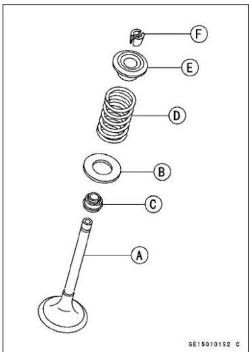
ValveGuideRemoval
- Remove:
Valve (see Valve Removal) OilSeal SpringSeat
- Heattheareaaroundthevalveguideto120\~150°C(248\~302°F),andhammerlightlyonthevalveguidearbor[A]toremovetheguidefromthetopofthehead.
SpecialTool-ValveGuideArbor, 4.5:57001-1331

natural_image
Close-up of a mechanical component with labeled point A and directional arrow (no readable text or symbols)CAUTION
Donotheatthecylinderheadwithatorch. This will warpthecylinderhead. Soakthecylinderhead and heattheoil.
Valves
ValveGuideInstallation
- Applyoiltothevalveguideoutersurfacebeforeinstallation.
- Heattheareaaroundthevalveguideholetoabout120\~150°C(248\~302°F).
CAUTION
Donotheatthecylinderheadwithatorch. This will warpthecylinderhead. Soakthecylinderhead and heattheoil.
- Drivethevalveguideinfromthetopoftheheadusing thevalveguidearboruntilthecirclipstopstheguidefrom goingintoofar.
SpecialTool-ValveGuideArbor,4.5:57001-1331
- Reamthevalveguidewithvalveguidereamer[A]evenif theoldguideisreused.
SpecialTool-ValveGuideReamer,4.5:57001-1333
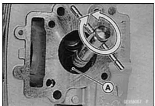
natural_image
Mechanical component diagram showing internal gears and a rotating arrow (no text or symbols)Valve-to-GuideClearanceMeasurement(Wobble Method)
Ifasmallboregaugeisnotavailable,inspectthevalve guidewearbymeasuringthevalvetovalveguideclearance withthewobblemethodasindicatedbelow.
- Insertanewvalve[A]intotheguide[B]andsetadial gaugeagainstthestemperpendiculartoitascloseas possibletothecylinderheadmatingsurface.
- Movethestembackandforth[C]tomeasurevalve/valve guideclearance.
- Repeatthemeasurementinadirectionatarightangleto thefirst.
★ Ifthereadingexceedstheservicelimit, replacetheguide.
NOTE
○Thereadingisnotactualvalve/valveguideclearance becausethemeasuringpointisabovetheguide.

Valve/ValveGuideClearance(WobbleMethod)
Standard:
Exhaust 0.14 \~ 0.19 mm (0.006 \~ 0.007 in.)
Inlet 0.03 \~ 0.13 mm (0.001 \~ 0.005 in.)
ServiceLimit:
Exhaust 0.38mm(0.015in.)
Inlet 0.33mm(0.013in.)
Valves
ValveSeatInspection
- Removethevalve(seeValveRemoval).
- Checkthevalveseatingsurface[A]betweenthevalve[B] andvalveseat[C].
○Measuretheoutsidediameter[D]oftheseatingpattern onthevalveseat.
★ Iftheoutsidediameteristoolargeortoosmall,repairthe seat(seeValveSeatRepair).
ValveSeatingSurfaceOutsideDiameter
Standard:
Exhaust 25.5 \~ 25.7 mm (1.00 \~ 1.01 in.)
Inlet 29.5 \~ 29.7 mm (1.16 \~ 1.17 in.)
○MeasuretheseatwidthEoftheportionwherethereis nobuild-upcarbon(whiteportion)ofthevalveseatwitha verniercaliper.
Good[F]
TooWide[G]
TooNarrow[H]
Uneven[J]
★ Ifthewidthistoowide, toonarroworuneven, repair the seat(seeValveSeatRepair).
ValveSeatingSurfaceWidth
Standard:
Exhaust, Inlet: 0.8 \~ 1.2 mm (0.03 \~ 0.05 in.)
ValveSeatRepair
- Repairthevalveseatwiththevalveseatcutters[A].
SpecialTools-ValveSeatCutterHolder,4.5:57001-1330
[B]
ValveSeatCutterHolderBar: 57001-1128
[C]
[ForExhaustValveSeat]
ValveSeatCutter,45°- φ27.5:57001-1114or30φ
57001-1187
ValveSeatCutter,32°- φ30:57001-1120
ValveSeatCutter,60°- φ30:57001-1123
○Valve Seat Cutter, 45°-φ30: 57001-1187 can also be used instead of Valve Seat Cutter, 45°-φ27.5:57001-1114
[ForInletValveSeat]
ValveSeatCutter,45°- φ32:57001-1115
ValveSeatCutter,32°- φ35: 57001-1121or φ3:
57001-1199
ValveSeatCutter,60°- φ33:57001-1334
○Valve Seat Cutter, 32°-φ33: 57001-1199 can also be used instead of Valve Seat Cutter, 32°-φ35: 57001-1121
★ Ifthemanufacturer's instructions are not available, use the following procedure.
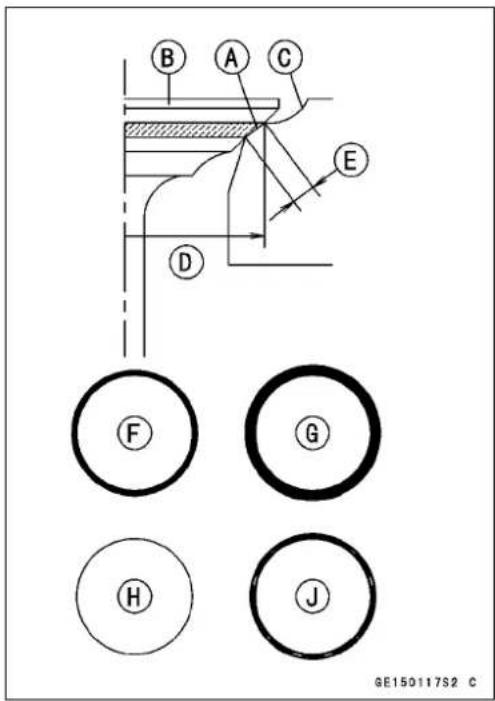

Valves
SeatCutterOperationCare
- This valveseatcutterisdeveloped to grind the valve for repair. Therefore the cutterm must not be used for other purpose sthan seat repair.
- Donotdroporshockthevalveseatcutter, orthedia-mondparticles may falloff.
- Donotfailtoapplyengineoiltothevalveseatcutter beforegrindingtheseatsurface. Also washoffground particlesstickingtothecutterwithwashingoil.
NOTE
○Donotuseawirebrushtoremovethemetalparticles fromthecutter.Itwilltakeoffthediamondparticles.
- Setting the valveseatcutterholderinposition, operate the cutterinonehand. Donotapplytoomuchforceto the diamond portion.
NOTE
○Priorogrinding, applyengineoiltothecutterandduringtheoperation, washoffanygroundparticlessticking tothecutterwithwashingoil.
- Afteruse, washit with washing oil and apply thin layer of engine oil before storing.
MarksStampedontheCutter
Themarksstampedonthebackofthecutter[A]represent the following.
60°....Cutterangle[B]
37.5 ....Outerdiameterofcutter[C]
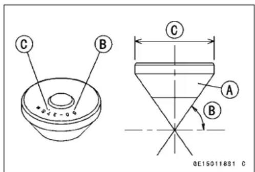
OperatingProcedures
- Cleantheseatareacarefully.
- Coattheseatwithmachinist'sdye.
- Fita45° cutter into the holder and slide it into the valve guide.
- Pressdownlightlyonthehandleandturnitrightorleft. Grindtheseatingsurfaceonlyuntilissmooth.
CAUTION
Donotgrindtheseattoomuch.Overgrindingwill reducevalveclearancebysinkingthevalveintothe head.Ifthevalvesinkstoofarintothehead,itwill beimpossibletoadjusttheclearance,andthecylinderheadmustbereplaced.
Valves
-
Measuretheoutsidediameteroftheseatingsurfacewithaverniercaliper.
★ Iftheoutsidediameteroftheseatingsurfaceistoosmall, repeatthe45°grinduntilthediameteriswithinthespecifiedrange.
WidenedWidth[A]ofengagementbymachiningwith 45°cutter
GroundVolume[B]by32°cutter 32°[C]
CorrectWidth[D]
GroundVolumeEby60°cutter 60°F -
Measuretheoutsidediametortheseatingsurfacewithaverniercaliper.
★Iftheoutsidediameteroftheseatingsurfaceistoosmall, repeatthe45°grind[A]untilthediamteriswithinthespecifiedrange.
OriginalSeatingSurface[B]
NOTE
○ Remove all pitting offlaws from 45° grounds surface.
○Aftergrindingwith45°cutter,applythincoatofmachinist'sdyetoseatingsurface. Thismakesseatingsurface distinctand32°and60°grindingoperationeasier.
○ Whenthevalveguideisreplaced, besuretogrind with 45° cutterforcentering and good contact.
★ Iftheoutsidediameter[A]oftheseatingsurfaceistoo large, makethe32°grinddescribedbelow.
★ Iftheoutsidediameteroftheseatingsurfaceiswithinthe specifiedrange,measuretheseatwidthasdescribedbelow.
- Grindtheseatata32°angle[B]untiltheseatoutside diameter.iswithinthespecifiedrange.


- Tomakethe32°grind, fita32°cutterintotheholder, and slideitintothevalveguide.
○Turntheholderoneturnatatimewhilepressingdown verylightly.Checktheseataftereachturn.
CAUTION
The32°cutterremovesmaterialveryquickly. Checktheseatoutsidediameterfrequentlytoppreventovergrinding.
○Aftermakingthe32°grind,returntotheseatoutsidediameter.measurementstepabove.
- Tomeasuretheseatwidth, useaverniercalipertomea-
surethewidthofthe45°angleportionoftheseatatseveralplacesaroundtheseat.
★ If theseatwidthistoonarrow, repeat the 45° grind until theseatisslightly toowide, and then return to theseat outsidediameter.measurementstepabove.
Valves
★ If theseatwidthhistoowide, makethe60°grind[A]describedbelow.
★ If theseatwidth this within the specified range, lap the valve to theseatas described below.
- Grindtheseatata60°angleuntiltheseatwidththiswithin thespecifiedrange.
○ Tomakethe60°grind, fit60°cutterintotheholder, and slideitintothevalveguide.
○Turntheholder,whilepressingdownlightly.
○ Aftermakingthe60°grind, returntotheseatwidthmeasurementstepabove.
CorrectWidth[B]
- Lapthevalvetotheseat, oncetheseatwidth and O.D. are within therangesspecified above.
-
Putalittlecoarsegrindingcompoundonthefaceofthe valveinanumberofplacesaroundthevalvehead.
○ Spinthevalveagainsttheseatuntilthegrindingcompoundproducesasmooth, matchedsurfaceonboththe seatandthevalve.
○ Repeat the process with a fine grinding compound. Lapper[A] ValveSeat[B] Valve[C] -
Theseatingareashouldbemarkedaboutinthemiddle ofthevalveface.
★ Iftheseatareaisnotintherightplaceonthevalve,check tobesurethevalveisthecorrectpart.Ifitis,itmayhave beenrefusedtoomuch;replaceit. - Besuretoremoveallgrindingcompoundbeforeassembly.
- Whentheengineisassembled, besuretoadjustthevalve clearance(seeValveClearanceAdjustment).
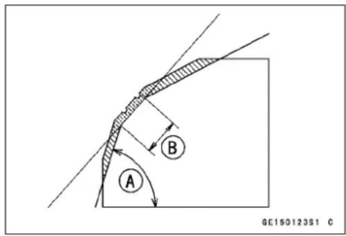

Valves
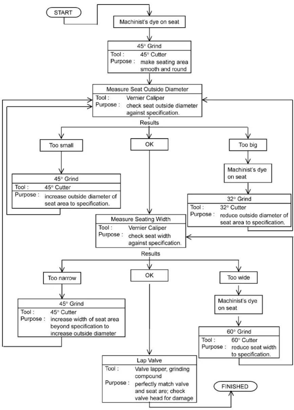
flowchart
graph TD
    A["START"] --> B["Machinist's dye on seat"]
    B --> C["45° Grind\nTool: 45° Cutter\nPurpose: make seating area smooth and round"]
    C --> D["Measure Seat Outside Diameter\nTool: Vernier Caliper\nPurpose: check seat outside diameter against specification."]
    D --> E["Results"]
    E --> F["Too small"]
    E --> G["OK"]
    E --> H["Too big"]
    F --> I["45° Grind\nTool: 45° Cutter\nPurpose: increase outside diameter of seat area to specification."]
    G --> J["Measure Seating Width\nTool: Vernier Caliper\nPurpose: check seat width against specification."]
    H --> K["Machinist's dye on seat"]
    K --> L["32° Grind\nTool: 32° Cutter\nPurpose: reduce outside diameter of seat area to specification."]
    L --> M["Results"]
    M --> N["Too narrow"]
    M --> O["OK"]
    M --> P["Too wide"]
    N --> Q["45° Grind\nTool: 45° Cutter\nPurpose: increase width of seat area beyond specification to increase outside diameter"]
    O --> R["Lap Valve\nTool: Valve lapper, grinding compound\nPurpose: perfectly match valve and seat are; check valve head for damage"]
    P --> S["Machinist's dye on seat"]
    S --> T["60° Grind\nTool: 60° Cutter\nPurpose: reduce seat width to specification."]
    T --> U["FINISHED"]
Cylinder, Piston
CylinderRemoval
- Remove:
CylinderHead(see CylinderHeadRemoval)
- Taplightlyupthecylinder[A]withaplasticmallettoseparatefromthecrankcase.
- Removethecylinderbasegasket.
PistonRemoval
- Removethecylinder(seeCylinderRemoval).
- Placeacleanclothunderthepistonandremovethepistonpinsnapring[A]fromtheoutsideofthepiston.
CAUTION
Donotreusesnaprings,asremovalweakensand deformsthem.Theycouldfalloutandscorethe cylinderwall.
- Removethepistonpin.
SpecialTools-PistonPinPullerAssembly:57001-910[A] Adapter[B] -
Removethepiston.
-
Carefullyspreadtheringopeningwithyourthumbsand thenpushupontheoppositeside[A]oftheringtoremove it.
- Removethe3-pieceoilringwithyourthumbsinthesame manner.
Cylinder, Piston Installation
NOTE
○Ifanewpistonorcylinderisused, checkpistontocylinder clearance(seePiston/CylinderClearance), and use newpistonring.
- Applyengineoiltotheinnersurfaceoftheconnectingrod smallend.
- Thetriangularmarkonthepistonheadmustpointtoward thefrontoftheengine.
- Fitanewpistonpinsnapringintothesideofthepiston sothattheringopening[A]doesnotcoincidewiththeslit [B]ofthepistonpinhole.

natural_image
Close-up of a car engine cylinder head with attached pipe and valve, no visible text or symbols
natural_image
Close-up mechanical assembly showing a piston and crankshaft mechanism (no visible text or symbols)

natural_image
Line drawing of a hand holding a mechanical component with a circular mark and directional arrows (no text or symbols)
4-34ENGINETOPEND
Cylinder, Piston
When installing the piston pinsnapring, compressit only enough to install it and nomore.
CAUTION
Donotreusesnaprings,asremovalweakensand deformsthem.Theycouldfalloutandscorethe cylinderwall.
NOTE
○ Theoilringrailshaveno "top" or "bottom".
- Installtheoilringexpander[A]inthebottompistonring groovesotheends[B]butttogether.
-
Installtheoilringsteelrails,oneabovetheexpanderand onebelowit.
○Spreadtherailwithyourthumbs,butonlyenoughtofit therailoverthepiston.
○Releasetherailintothebottompistonringgroove. -
Donotmixupthetopringandsecondring.
- Installthesecondring[C]sothatthe"RN"mark[D]faces up.
- Installthetopring[A]sothatthe"R"mark[B]facesup.
- Install: DowelPins[A] NewCylinderBaseGasket[B]
- Thepistonringopeningsmustbepositionedasshownin thefigure.Theopeningsoftheoilringsteelrailsmustbe about30\~40°ofanglefromtheopeningofthetopring. TopRing[A] SecondRing[B] OilRingSteelRails[C] OilRingExpander[D] TriangularMarkE

chemical
Chemical structure diagram showing a polymer chain with labeled points A and B, likely representing a polymer or functional group.
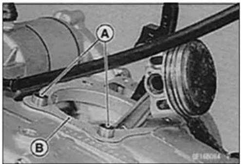

Cylinder, Piston
- Applyengineoiltothecylinderbore.
- Positionthepistonringopenings.
- Installthecylinder[B]whilecompressing[A]thepiston ringswithyourthumbs.
• Installtheremovedparts.

CylinderWear
- Sincethereisadifferenceincylinderwearindifferentdirections, takeaside-to-sideandafront-to-backmeasurementateachofthethreelocations(totalofsixmeasurements)showninthefigure.
10mm(0.39in.)[A]
40mm(1.57in.)[B]
20mm(0.79in.)[C]
★ Ifanyofthecylinderinsidediametermeasurementsexceedstheservicelimit,replacethecylinder.

CylinderInsideDiameter
Standard: 55.000 \~ 55.012 mm (2.1654 \~ 2.1658 in.), and less than 0.01 mm (0.0004 in.) difference between any two measurements.
ServiceLimit:55.10mm(2.169in.),or0.05mm (0.002in.)differencebetweenanytwo measurements.
PistonWear
- Measuretheoutsidediameter[A]ofeachpiston5mm (0.20in.)[B]upfromthebottomofthepistonataright angletothedirectionofthepistonpin.
★ Ifthemeasurementisunderservicelimit, replacethepiston.
PistonDiameter
Standard: 54.960 \~ 54.975 mm (2.1638 \~ 2.1644 in.) 54.968 \~ 54.982 mm (2.1641 \~ 2.1646 in.) (BN125-A7\~, N, N U) N:NoCatalyticConverterModel NU:NoCatalyticConverter(United KingdomModel)
ServiceLimit:54.81mm(2.158in.)

Piston/CylinderClearance
- Subtract the pistondiameter from the cylinder insidediametertoget the piston/cylinder clearance.
Piston/CylinderClearance
Standard: 0.025 \~ 0.052 mm (0.0010 \~ 0.0020 in.)
★Ifthepiston/cylinderclearanceislessthanthespecified range,useasmallerpistonorincreasethecylinderinside diameterbyhoning.
★ Ifthepiston/cylinderclearance is greater than specified range, usealarger piston.
★Ifonlyapistonisreplaced, theclearancemayexceedthe standardslightly. Butitmustnotbelessthantheminimum inordertoavoidpistonseizure.
PistonRing, PistonRing Groove Wear
- Checkforunevengroovewearbyinspectingtheringseating.
★Theringsshouldfitperfectlyparalleltogroovesurfaces. Ifnot, replacethepistonandallthepistonrings. - With the piston rings in their grooves, makes several measurements with a thickness gauge [A] to determine piston ring/groove clearance.
PistonRing/GrooveClearance
Standard:
Top 0.03 \~ 0.07 mm (0.0012 \~ 0.0028 in.)
Second 0.02 \~ 0.06 mm (0.0008 \~ 0.0024 in.)
ServiceLimit:
Top 0.17mm(0.0067in.)
Second0.16mm(0.0063in.)
★Ifthepistonringgrooveclearanceisgreaterthantheservicelimit,measuretheringthicknessandgroovewidthas followstodecidewhethertoreplacetherings,thepiston orboth.
PistonRingGrooveWidth
- Measurethepistonringgroovewidth.
○Useaverniercaliperatseveralpointsaroundthepiston.
PistonRingGrooveWidth
Standard:
Top 0.82 \~ 0.84 mm (0.0323 \~ 0.0331 in.)
Second 0.81 \~ 0.83 mm (0.0319 \~ 0.0327 in.)
ServiceLimit:
Top 0.92mm(0.0362in.)
Second0.91mm(0.0358in.)
★ If the width of any of the two grooves is wider than the service limit at an midpoint, replace the piston.

natural_image
Line drawing of hands assembling a mechanical component with a labeled part (A), no text or symbols present.Cylinder, Piston
PistonRingThickness
- Measurethepistonringthickness.
○Useamicrometertomeasureatseveralpointsaround thering.
PistonRingThickness(Top, Second)
Standard: 0.77 \~ 0.79 mm (0.0303 \~ 0.0311 in.)
ServiceLimit:0.70mm(0.028in.)
★ Ifanyofthemeasurementsislessthantheservicelimit oneitheroftherings,replacealltherings.
NOTE
○Whenusingnewringsinausedpiston, checkforun-evengroovewear. Theringsshouldfitperfectlyparallel tothegroovesides. Ifnot, replacethepiston.
PistonRingEndGap
- Placethepistonring[A]insidethecylinder,usingthepistontolocatetheringsquarelyinplace.Setitclosetothe bottomofthecylinder,wherecylinderwearislow.
- Measurethegap[B]betweentheendsoftheringwitha thicknessgauge.
PistonRingEndGap
Standard:
Top 0.15 \~ 0.30 mm (0.006 \~ 0.012 in.)
Second 0.30 \~ 0.45 mm (0.012 \~ 0.018 in.)
Oil 0.20 \~ 0.70 mm (0.008 \~ 0.028 in.)
ServiceLimit:
Top 0.6mm(0.024in.)
Second0.7mm(0.028in.)
Oil1.0mm(0.04in.)
★ Iftheendgapofeitherringisgreaterthantheservice limit,replacealltherings.
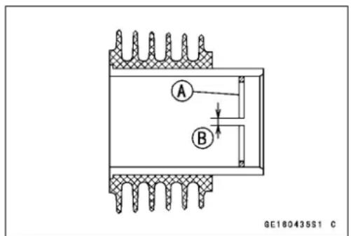
4-38ENGINETOPEND
CarburetorHolder
CarburetorHolderInstallation
- ApplygreasetotheO-ring[A], and install the carburetor holder.
○TakecarenottopinchtheO-ring.
- Tighten:
Torque-CarburetorHolderBolts:9.8N·m(1.0kgf·m,87in·lb)
- Installtheinsulator[B]sothatitsrecessalignswiththe boss[A]onthecarburetorholder.

natural_image
Close-up of a mechanical component with labeled parts (A) and no visible text or symbols beyond the label.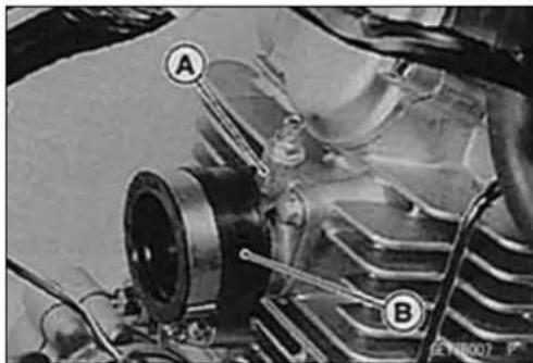
natural_image
Close-up of a mechanical assembly with labeled parts A and B, showing internal components and wiring (no readable text or symbols beyond labels)Muffler
WARNING
Toavoidaserlousburn, donotremovethemuffler whentheengineisstillhot. Waituntilthemuffler coolsdown.
MufflerRemoval
- loosenthemufflerbodyclampbolt[A].
-
Removethemufflerbodymountingboltandnut[B].
-
Removethemufflerbody[A]backward.
- Removetheexhaustpipemountingbolt[B].
- Remove:
ExhaustPipeHolderNuts[A] ExhaustPipe[B]
NOTE
○Whenremovingthemufflerbodyandexhaustpipeassembly, donotloosenthemufflerbodyclampbolt.
MufflerInstallation
- Checktheexhaustpipeholdergasketforsingsofdamage.
★ Ifnecessary, replacethegasketwithanewone. - Checkthegasket[A]oftheclampforsingsofdamage andthatitfitsinplacesecurely.
★ Ifnecessary, replacethegasketwithanewone. - Tighten:
Torque-MufflerBodyMountingNut:15N·m(1.5kgf·m,11ft·lb)
- Firsttightenalltheboltsandnutstoasnugfit.
- Nexttightentheexhaustpipeholdernutsevenlytoavoid exhaustleaks.
- Lastly, tightentherestoftheboltsandclampboltsecurely.
- Thoroughlywarmuptheengine, waituntiltheengine coolsdown, and thenretightentheexhaustpipeholder nuts, and the clampbolt securely.

natural_image
Close-up of a motorcycle's side panel showing engine components and a labeled section (A) with no readable text or symbols.


natural_image
Close-up of a mechanical component with a labeled section A, showing internal structure and mounting points (no readable text or symbols)Clutch
TableofContents
Exploded View 5-2
Specifications 5-4
Special Tools 5-5
Clutch Lever and Cable 5-6
Clutch Lever Free Play Inspection 5-6
ClutchLeverFreePlayAdjustment....5-6
Clutch Lever Installation.... 5-6
Clutch Cable Removal 5-6
Clutch Cable Installation 5-6
Clutch Cable Lubrication 5-6
Clutch Cover 5-7
Clutch Cover Removal 5-7
Clutch Cover Installation 5-7
Clutch Cover Assembly 5-8
Clutch 5-9
Clutch Removal 5-9
Clutch Installation 5-9
FrictionandSteelPlateDamage,Wear....5-10
Friction and Steel Plate Warp 5-10
ClutchSpringFreeLengthMeasurement....5-11
Clutch Housing Finger Damage.... 5-11
Clutch Hub Spline Damage.... 5-11
Primary Gear 5-12
Primary Gear Removal 5-12
Primary Gear Installation 5-12
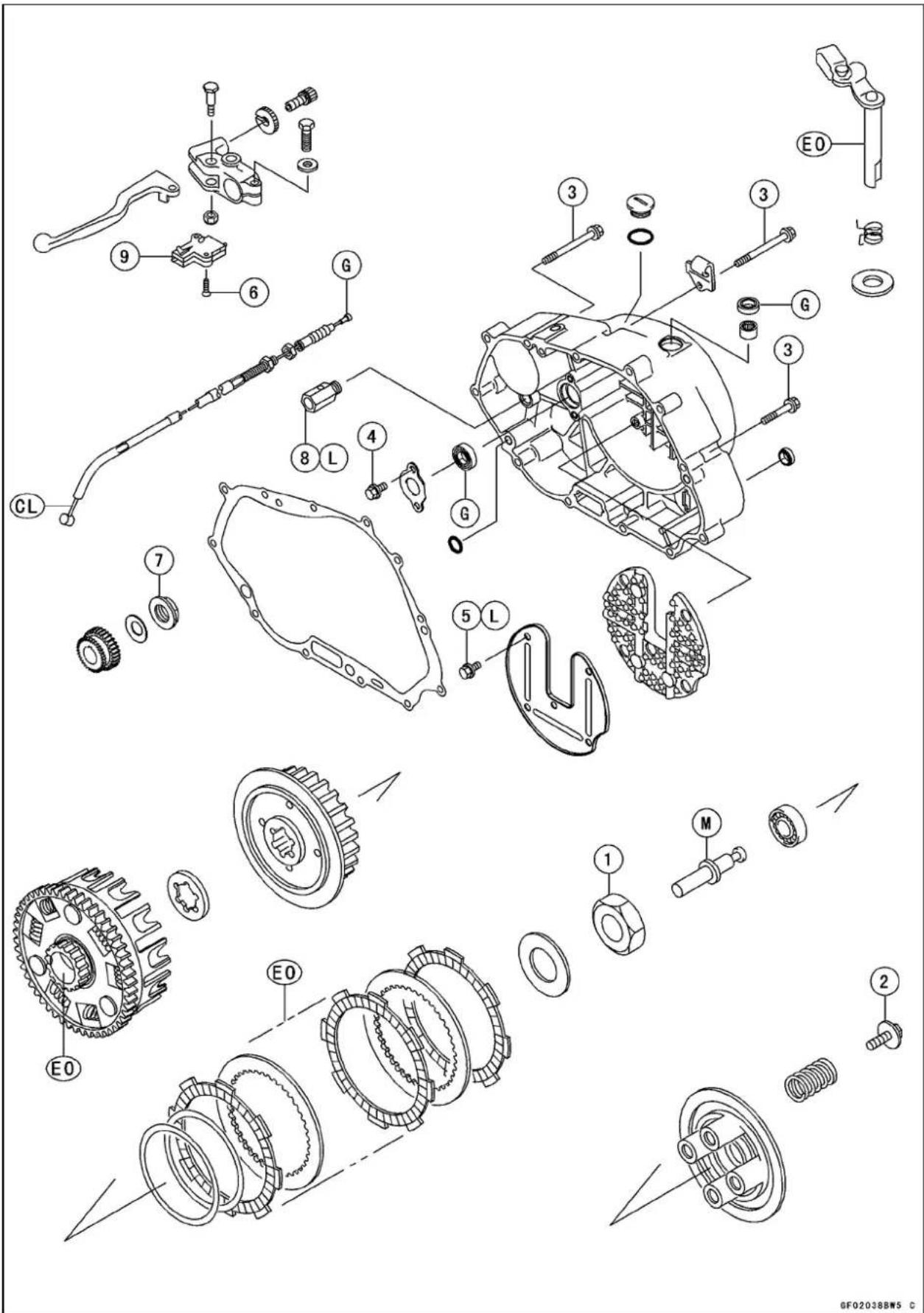
ExplodedView
| No.Fastener | Torque | Remarks | |||
| N·mkgf·mft·lb | |||||
| 1ClutchHubNut9810.072 | |||||
| 2ClutchSpringBolt8.80.9078in·lb | |||||
| ClutchCoverBolts(BN125-A1~A3) | 9.81.087in·lb | ||||
| Clutch Cover Bolts (BN125-A4 ~) | 8.8 | 0.90 | 78 in·lb | ||
| Oil Seal Retaining Plate Bolts (BN125-A1 ~ A3) | 9.81.087in·lb | ||||
| Oil Seal Retaining Plate Bolts (BN125-A4 ~) | 8.8 | 0.90 | 78 in·lb | ||
| 5 | Clutch Cover Damper Bolt | 8.8 | 0.90 | 78 in·lb | L |
| 6 | Starter Lockout Switch Screws | 1.0 | 0.10 | 9 in·lb | |
| 7 | PrimaryGearNut | 69 | 7.0 | 11 | |
| 8 | Oil Pressure Relief Valve | 15 | 1.5 | 11 | L |
- Starter lockoutswitch
CL: Apply cablelubricant.
EO: Apply engineoil.
G: Apply grease.
L: Applyanon-parmanent lockingagent.
M: Applymolybdenumdisulfide grease.
Specifications
| ItemStandardServiceLimit | ||
| Clutch Lever Free Play | 2 ~ 3 mm (0.08 ~ 0.12 in.) | -- -- |
| Clutch | ||
| Friction Plate Thickness | 2.92 ~ 3.08 mm (0.115 ~ 0.121 in.) | 2.8 mm (0.11 in.) |
| Friction and Steel Plate Warp | 0.2 mm (0.008 in.) or less | 0.3 mm (0.012 in.) |
| Clutch Spring Free Length | 35.0 mm (1.38 in.) | 34.0 mm (1.34 in.) |
SpecialTools
GearHolder,m1.75: 57001-1015

natural_image
Technical line drawing of a mechanical gear assembly with no visible text or symbolsClutchHolder: 57001-1243

natural_image
Technical line drawing of a mechanical clamp or lever assembly (no text or symbols)ClutchLeverandCable
Duetofrictionplatewearandclutchcablestretchchover alongperiodofuse, theclutchmustbeadjustedinaccordancewiththePeriodicMaintenanceChart.
ClutchLeverFreePlayInspection
- RefertotheClutchLeverFreePlayInspectioninthePeriodicMaintenancechapter.
ClutchLeverFreePlayAdjustment
- RefertotheClutchLeverFreePlayAdjustmentinthe PeriodicMaintenancechapter.
ClutchLeverInstallation
- Installtheclutchleversothatthematingsurfaceofthe leverholderisalignedwiththepunchmark[A]onthe handlebar.
ClutchCableRemoval
- Loosenthelocknut[A]attheclutchlever,andscrewin theadjuster[B].
- Lineuptheslots[C]intheclutchlever,locknut,andadjusterandthenfreethecablefromthelever.
- Freetheclutchinnercabletipfromtheclutchrelease lever.
- Pushthereleaselevertowardthefrontofthemotorcycle andtapethereleaselevertotheclochcovertoprevent thereleaseshaftfromfallingout.
- Pulltheclutchcableoutoftheframe.
ClutchCableInstallation
- Runtheclutchcablecorrectly(seeAppendixchapter).
- Adjusttheclutchleverfreeplay(seePeriodicMaintenancechapter).
ClutchCableLubrication
- RefertotheGeneralLubricationinthePeriodicMaintenancechapter.
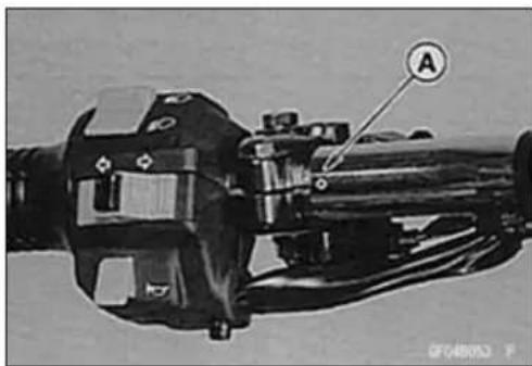
natural_image
Mechanical assembly diagram showing a shaft and housing component with labeled point A (no text or symbols beyond label)
ClutchCover
ClutchCoverRemoval
- Draintheengineoil(seePeriodicMaintenancechapter).
- Remove:
FrontFootpeg OilPipeBanjoBolt[A]
- Screwtheclutchleveradjusterincompletelysoastogivetheclutchcableplentyofplay.
- Removetheclutchcableholder[B]ofclutchreleaselever.
- Freetheclutchinnercabletipfromtheclutchrelease lever[C].
- Removetheclutchcoverbolts, and removetheclutch cover[A].
○Turnthereleaselevertowardthereartofreetherlease shaft[B]fromtheclutchspringplatepusherandremove theclutchcover.
CAUTION
Donotremovetheclutchreleaseleverandshaft assemblyunlessitisabsolutelynecessary.Ifremoved,theoilsealreplacementmayberequired. Applyhightemperaturegreasetotheoilseallips.
ClutchCoverInstallation
- Installthedowelpins[A]andreplacethecovergasket withanewone.
-
InstalltheO-ring[B].
-
Installtheclutchcoverwiththeclutchreleaselevertoward therear.
- Enginetheclutchreleaseshaftwiththeclutchspringplate pusherbyturningtheclutchreleaselever[A]towardthe front.
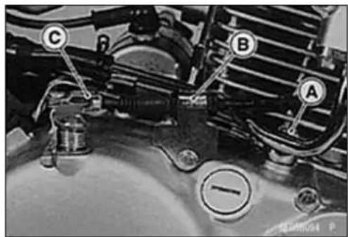


natural_image
Mechanical assembly diagram showing gears and housing components (no text or labels visible)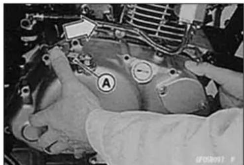
natural_image
Close-up of a car engine bay with labeled components (A) and a hand holding a tool, no readable text or symbols present.ClutchCover
- Withtheshaftpulledalittleoutofthecover,turnthelever untilbecomeshardtoturn.
○Thereleaselevershouldhaveabout11mm(0.43in.)[A] clearancebetweentheleverandthewasher.
- Tightenthecoverboltsandclutchcableholderbolts. ○Whilepushing[B]theclutchcableholder[A]rearward untiltheholdertouchestheclutchcover,tightentheclutch cableholderbolt.
Torque-ClutchCoverBolts
(BN125-A1\~A3):9.8N·m(1.0kgf·m,87in·lb)
(BN125-A4 \~): 8.8 N·m (0.90 kgf·m, 78 in·lb)
- Replacethebanjoboltwasherswithnewones.
- Tightentheoilpipebanjobolt.
Torque-OilPipeBanjoBolt:25N·m(2.5kgf·m,18in·lb)
- Pourinthespecifiedtypeandamountofoil(seePeriodic Maintenancechapter).
• Installthefrontfootpeg.
- Adjustandinspectthefollowing.
ClutchLeverFreePlay RearBrake
RearBrakeLightSwitch
WARNING
Ifafullbrakepedalisnotobtained,disassemble andinspecttherearbrakeparts.
Wornpartscauselockofthebrakeorlossofbraking.
ClutchCoverAssembly
- Installtheoilsealretainerwiththe"UP"markfacing[A] upward.
★Iftheoilsealisdamaged,replaceitwithanewone.
- Tighten:
Torque-OilSealRetainingPlateBolts
(BN125-A1\~A3):9.8N·m(1.0kgf·m,87in·lb)
(BN125-A4 \~): 8.8 N·m (0.90 kgf·m, 78 in·lb)

natural_image
Close-up of an automotive engine bay with hoses and a labeled component (A), no readable text or symbols present.
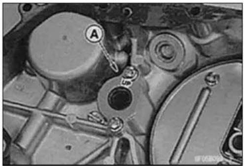
natural_image
Close-up mechanical component with labeled parts (A and 5), no readable text or symbols beyond labelsClutch
ClutchRemoval
- Removetheclutchcover(seeClutchCoverRemoval).
NOTE
○Iftheprimarygearistoberemoved,removetheprimarygearnutbeforeclutchremoval(seePrimaryGearRemoval).
- Remove:
ClutchSpringBolts[A]withSprings ClutchSpringPlate[B] BallBearingandPusher[C] FrictionPlatesandSteelPlates
- Usingtheclutchholder[A], holdthehubtoremovethe clutchhubnut[B].
SpecialTool-ClutchHolder:57001-1243 - Removethespringwasher.
- Remove:
ClutchHub[A] Spacer[B] ClutchHousing[C]


natural_image
Mechanical assembly diagram showing gear and housing components (no readable text or symbols)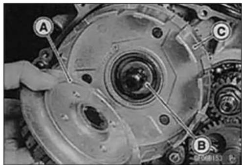
ClutchInstallation
- Applymolybdenumdisulfidegreasetotheclutchhousing bearinghole[A].
- Install: ClutchHousing[B] Spacer ClutchHub

natural_image
Mechanical gear assembly with labeled components (A and B), no visible text or symbols beyond labelsClutch
• Installthewasher[A]asshown.
CrankcaseSide[B]
- Tightentheclutchhubnut[C], while holding the clutch hub with the clutch holder.
SpecialTool-ClutchHolder:57001-1243
Torque-ClutchHubNut:98N·m(10.0kgf·m,72ft·lb)
- Installthespringseat[B], and thenthespring[C] with the concaveside facing to the clutch cover.
- Wheninstallingthefrictionplatesandsteelplates,firstinstallthefrictionplate[A]whoseinsidediameterislarger thantheothersandtheninstallasteelplate[D]andalternatingthem.
CAUTION
If new dry friction plates and steel plates are installed, apply engine oil to the surfaces of each plateto avoid clutch plates seizure.
- Applymolybdenumdisulfidegreasetothepusherends [A]andinstallthethrustbearing.
- Tightentheclutchspringbolts.
Torque-ClutchSpringBolts:8.8N·m(0.90kgf·m,78in·lb)
FrictionandSteelPlateDamage, Wear
- Visually inspect the friction and steel plates for sign of seizure, overheating (discoloration), or uneven wear.
- Measurethethicknessofthefrictionplates[A]atseveral points.
★Ifanyplatesshowsignsofdamage,oriftheyhaveworn pasttheservicelimit,replacethemwithnewones.
FrictionPlateThickness
Standard: 2.92 \~ 3.08 mm (0.115 \~ 0.121 in.)
ServiceLimit:2.8mm(0.11in.)
FrictionandSteelPlateWarp
- Placefrictionplateorsteelplate[B]onasurfaceplate, andmeasurethegapbetweenhesurfaceplate[A]with athicknessgauge[C].Thegapistheamountoffriction orsteelplatewarp.
★ Ifanyplateiswarpedovertheservicelimit,replaceitwith anewone.
FrictionandSteelPlateWarp
Standard:0.2mm(0.008in.)orless
ServiceLimit: 0.3mm(0.012in.)

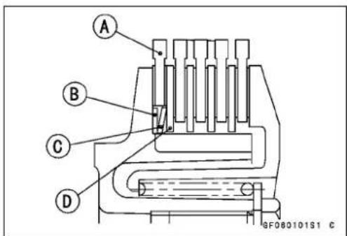

natural_image
Close-up mechanical assembly showing gear and shaft components (no visible text or symbols)

Clutch
ClutchSpringFreeLengthMeasurement
- Measurethefreelengthoftheclutchsprings[A].
★ Ifanyspringisshorterthantheservicelimit, it must be replaced.
ClutchSpringFreeLength
Standard:35.0mm(1.38in.)
ServiceLimit:34.0mm(1.34in.)

ClutchHousingFingerDamage
- Visuallyinspecttheclutchhousingfingers[A]wherethe frictionplatetangshitthem.
★ Iftheyarebadlywornoriftherearegroovecutswhrethe tangshit,replacethehosing.Also,replacethefriction platesiftheirtangsaredamaged.
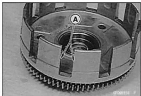
natural_image
Close-up of a mechanical component with visible teeth and central bore, no text or symbols presentClutchHubSplineDamage
- Visuallyinspectwheretheteethonthesteelplateswear againsttheclutchhubsplines.
★ Iftherearenotcheswornintotheclutchhubsplines[A], replacetheclutchhub. Also, replacethesteelpatesif theirteetharedamaged.

natural_image
Mechanical component with labeled section A, showing internal gears and housing (no readable text or symbols)PrimaryGear
PrimaryGearRemoval
- Removetheclutchcover(seeClutchCoverRemoval).
- Using the gearholder[A], hold the primary gear and loosent the primary gear nut[B].
SpecialTool-GearHolder,m1.75:57001-1015
- Remove:
Clutch(seeClutchRemoval)[C]
PrimaryGearNut[B]
SpringWasher
PrimaryGear[D]
WoodruffKey
PrimaryGearInstallation
- Fitthewoodruffkey[B]securelyintheslotbeforeinstallingtheprimarygear[A].
- Installthespringwasher[A]withtheconcavesidefacing tothecrankcase.
-
Installtheclutch.
• Temporarilytightentheprimarygearnut[B]. -
Using the gearholder[A], hold the primary gearasshown.
- Tightentheprimarygearnut[B].
Torque-PrimaryGearNut:69N·m(7.0kgf·m,51ft·lb)
SpecialTool-GearHolder,m1.75:57001-1015
- Installtheclutchcover(seeClutchCoverInstallation).


natural_image
Mechanical gear assembly diagram showing two labeled components (A and B) with no visible text or symbols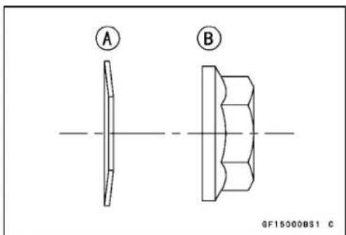

natural_image
Mechanical gear assembly diagram showing interlocking gears and a labeled component (A, B), no readable text or symbols present.EngineLubricationSystem
TableofContents
Exploded View 6-2
Engine Oil Flow Chart 6-4
Specifications 6-5
Special Tools 6-6
Engine Oil and Oil Filter 6-7
Oil Level Inspection.... 6-7
Engine Oil Change 6-7
Oil Filter Change 6-7
Oil Screen 6-8
Oil Screen Removal 6-8
Oil Screen Installation 6-8
Oil Pump 6-9
Oil Pump Removal 6-9
Oil Pump Installation 6-9
Oil Pump Disassembly 6-9
Oil Pump Assembly 6-10
Oil Pump Inspection 6-10
Oil Pressure 6-11
Oil Pressure Measurement 6-11
Relief Valve 6-12
Relief Valve Inspection.... 6-12
Oil Pipe 6-13
Oil Pipe Removal 6-13
Oil Pipe Installation 6-13
ExplodedView

ExplodedView
| No.Fastener | Torque | Remarks | |||
| N·mkgf | ·mft·lb | ||||
| 1EngineOilDrainPlug181.813 | |||||
| 2 | Oil Screen Cover Bolts (BN125-A1 ~ A3) | 9.8 | 1.0 | 87 in·lb | |
| Oil Screen Cover Bolts (BN125-A4 ~) | 8.8 | 0.90 | 78in·lb | ||
| 3 | Oil Pressure Relief Valve | 15 | 1.5 | 11 | L |
| 4 | Oil Filter Cover Bolts (BN125-A1 ~ A3) | 9.8 | 1.0 | 87 in·lb | |
| Oil Filter Cover Bolts (BN125-A4 ~) | 8.8 | 0.90 | 78 in·lb | ||
| 5 | Oil Pump Mounting Screws | 4.9 | 0.50 | 43 in·lb | |
| 6 | Oil Pump Assembly Screw | 9.8 | 1.0 | 87 in·lb | |
| 7 | OilPipeBanjoBolt(ClutchCover) | 252.619 | S | ||
| 8 | Oil Pipe Banjo Bolt (Left Crankcase) | 9.8 | 1.0 | 87 in·lb | S |
| 9 | Oil Pipe Banjo Bolt (Cylinder Head) | 9.8 | 1.0 | 87 in·lb | S |
| 10 | Oil Pipe Mounting Bolts (BN125-A1 ~ A3) | 9.8 | 1.0 | 87 in·lb | |
| Oil Pipe Mounting Bolts (BN125-A4 ~) | 8.8 | 0.90 | 78 in·lb | ||
| 11 | Oil Filler Plug | 2.5 | 0.25 | 22 in·lb | |
EO:Applyengineoil.
G:Applygrease.
L: Applyanon-permanentlockingagent.
R: Replacementparts
S: Followthespecifictighteningsequence.
EngineOilFlowChart
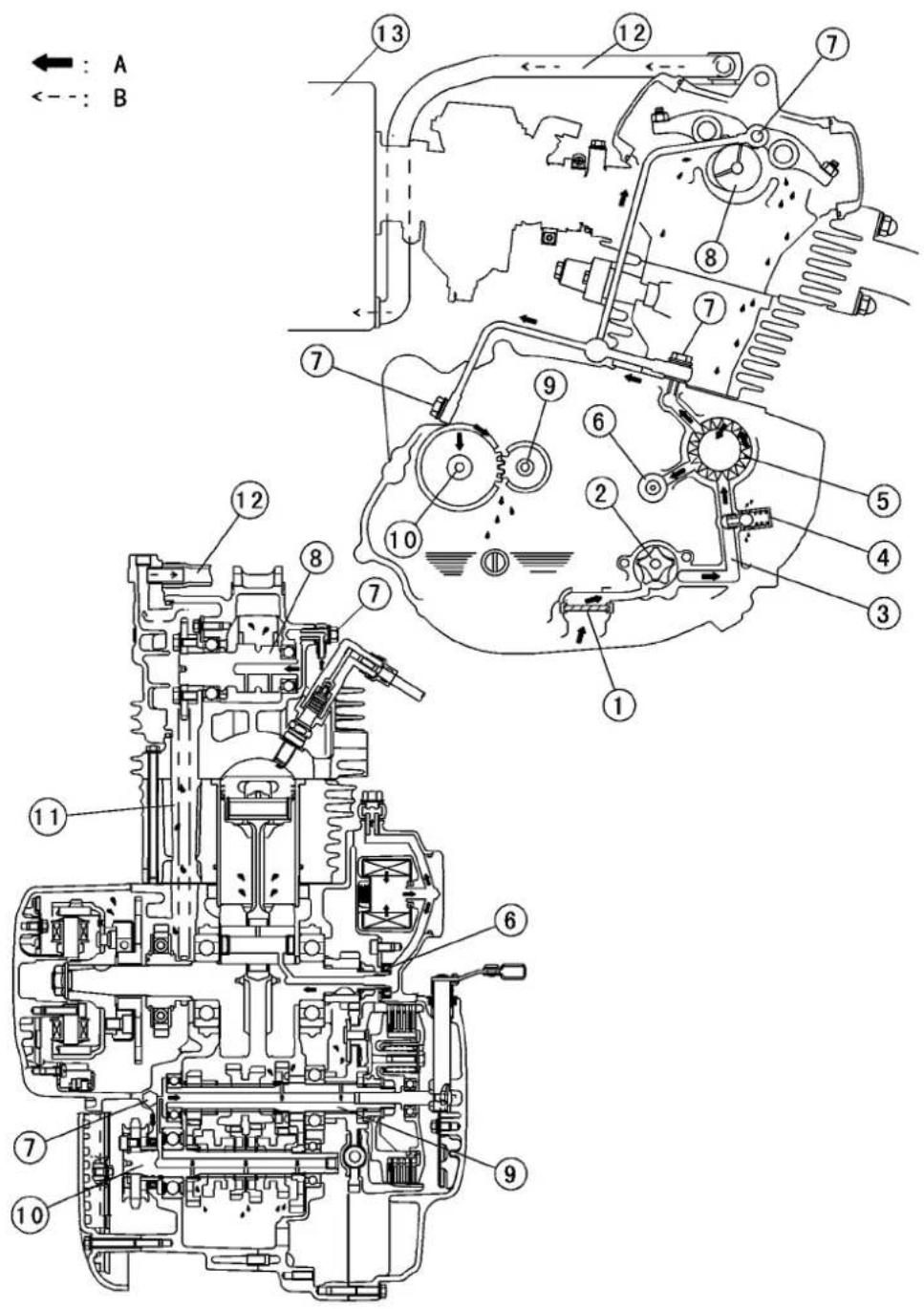
0604010BW4 C
1.Oilscreen
2.Oilpump
3. ClutchCoverOilPassage
4.OilPressureReliefValve
5.OilFilter
6.CrankshaftOilseal
7.OilPipeBanjoBolts
8.Camshaft
9.DriveShaft
10. OutputShaft
11.CamshaftChainTunnel
12. EngineBreatherHose
13.AirCleanerHousing
A.OilFlow
B.BlowbyGas
Specifications
| ItemStandard | |
| EngineOilGrade:(BN125-A1~A3)APISE,SForSG(BN125-A4~)APISE,SForSGViscositySAE10W-40Capacity1.1L(1.16USqt)(whenfilterisnotremoved)LevelBetweenupperandlowerlevellines | APISH,SJorSLwithJASOMA1.2L(1.27USqt)(whenfilterisremoved)1.4L(1.48USqt)(whenengineiscompletelydry) |
| OilPressureMeasurementOilPressure@4000r/min(rpm),OilTemperature90°C(194°F) | 13 ~ 32 kPa (0.13 ~ 0.33 kgf/cm2, 1.8 ~ 4.7 psi) |
SpecialTools
OilPressureGauge,5kgf/cm²: 57001-125
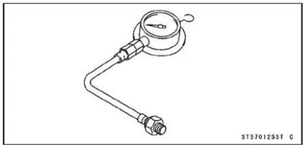
natural_image
Technical line drawing of a pressure gauge with attached pipe fitting (no text or symbols)OilPressureGaugeAdapter,M10×1.25:57001-1182
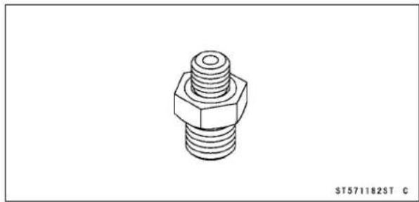
natural_image
Technical line drawing of a hexagonal bolt with threaded shaft (no text or symbols)EngineOilandOilFilter
WARNING
Motorcycleoperationwithinsufficient,deteriorated,orcontaminatedengineoilwillcause acceleratedwearandmayresultinengineortransmissionseizure,accident,andinjury.
OilLevelInspection
- Situatethemotorcyclesothatitisvertical.
- Check that the engine oil level is between the upper [A] and lower [B] levels in the gauge.
NOTE
○Situate themotorcycles that atitisperpendicularto the ground.
○Ifthemotorcyclehasjustbeenused, waitseveralminutesforalltheoiltodraindown.
○Iftheoilhasjustbeenchanged,starttheengineand runitforseveralminutesatidlespeed. Thisfillstheoil filterwithoil. Stoptheengine,thenwaitseveralminutes untiltheoilsettles.
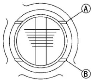
GG050108S1 C
CAUTION
Racingtheenginebeforetheoilreacheseverypart cancauseengineseizure.
★ Iftheoillevelistoohigh,removetheexcessoilthrough thefilleropening,usingasyringeorsomeothersuitable device.
★ If the oil level to oil, add the correct amount of oil through the oil filler opening. Use the same type and make of oil that is already in the engine.
NOTE
○Iftheengineoiltypeandmakeareunknown,useany brandofthespecifiedoiltotopoffthelevelratherthan runningtheenginewiththeoillevellow. Thenatyour earliestconvenience,changetheoilcompletely.
EngineOilChange
- RefertotheEngineOilChangeinthePeriodicMaintenancechapter.
OilFilterChange
- RefertotheOilFilterChangeinthePeriodicMaintenance chapter.
6-8 ENGINE LUBRICATION SYSTEM
OilScreen
OilScreenRemoval
- RefertotheOilScreenCleaninginthePeriodicMaintenancechapter.
OilScreenInstallation
- RefertotheOilScreenCleaninginthePeriodicMaintenancechapter.
OilPump
OilPumpRemoval
- Removetheclutchcover(seeClutchchapter).
- Removethemountingscrews[A]andremovetheoil pumpassembly[B].
○Turnthepumpgearsothatthepumpmountingscrews canberemovedthroughthepumpgearholes.
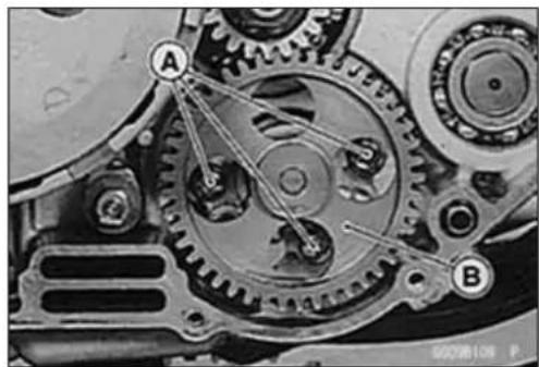
natural_image
Mechanical gear assembly diagram showing two labeled components A and B, with no visible text or symbols beyond labels.OilPumpInstallation
- ReplacetheO-ringswithnewones.
- InstalltheO-rings[A].
- Installthedowelpin[B].
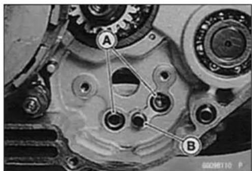
• Installtheoilpumpassembly.
- Tighten:
Torque-OilPumpMountingScrews[A]:4.9N·m(0.50 kgf·m,43in·lb)
- Installtheclutchcover(seeClutchchapter).
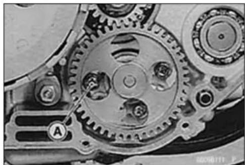
natural_image
Close-up mechanical gear assembly with labeled component A (no readable text or symbols)OilPumpDisassembly
- Remove:
OilPump(seethischapter)
CirclipandWasher[A]
OilPumpAssemblyScrew[B]
- Removetheoilpumpcover[C].

- Remove:
InnerRotor[A]
OuterRotor[B]

OilPump
OilPumpAssembly
• Installtheoilpumpgear[A].
- Filltherotors[B]withengineoil.
- Installthecoverandtightentheoilpumpassemblyscrew.
Torque-OilPumpAssemblyScrew:9.8N·m(1.0kgf·m,87in·lb)
• Installthewasherandcirclip.
- ReplacetheO-ringswithnewones.
- Check that the pump gear turns freely after assembly.
OilPumpInspection
- Disassembletheoilpump(seeOilPumpDisassembly).
- Visually inspect the oil pump body, outer and inner rotors, and cover.
★ If there is any damage or uneven wear, replacether rotors, cover, body, or the oil pump assembly.
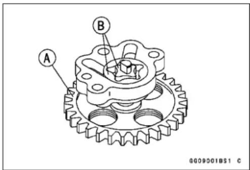
OilPressure
OilPressureMeasurement
- RemovetheairsuctionvalveA.
- Replacetheoilpipebanjoboltoftheclutchcover[B]with theoilpressuregaugeadapter(specialtool)[C].
★ If the oil pressure gauge adapter bottoms out, add washer(s)(P/N:11009-1105)[D] under the adapter. - AttachtheoilPressuregaugeE.
SpecialTools-OilPressureGauge,5kgf/cm²:57001-125 OilPressureGaugeAdapter,M10×1.25: 57001-1376
- Installtheairsuctionvalve(seeEngineTopEndchapter).
- Starttheengineandwarmuptheenginethoroughly.
- Runtheengineatthespecifiedspeed,andreadtheoil pressuregauge.
★ If the oil pressure is much lower than the standard, check the oil pump, crank shaft oil seal of the clutch cover and oil pump relief valve.
★ Ifthereadingismuchhigherthanthestandard,checkthe oilpumpscreenandtheoilfilterfirst,andoilpassagesfor dirtorclogging.

OilPressure
Standard: 13 \~ 32 kPa (0.13 \~ 0.33 kgf/cm², 1.8 \~ 4.7 psi)@4000r/min(rpm),oiltemperature 90°C(194°F)
- Stoptheengine, and removetheoil pressure gauge and adapter.
WARNING
Takecareagainstburnsfromhotengineoilthatwill drainthroughtheoilpassagewhentheoilpressure gaugeadapterisremoved.
• Installthenewcopperwashers.
- Tighten:
Torque-OilPipeBanjoBolt:25N·m(2.5kgf·m,18ft·lb)
ReliefValve
ReliefValveInspection
- Removethereliefvalvefromtheclutchcover.
- Checktoseeifthevalve[A]slidessmoothlywhenpushinginwithawoodenorthersoftrod,andseeifitcomes backtoitsseatbyspring[B]pressure.
NOTE
○ Inspectthevalveinitassembledstate.Disassembly andassemblymaychangethevalveperformance.
★Ifanyroughsportsarefoundduringaboveinspection, washthevalvecleanwithahigh-flashpointsolventand blowoutanyforeignparticlesthatmaybeinthevalvewith compressedair.

WARNING
Cleanthereliefvalveinawell-ventilatedarea,and takecarethatthereisnosparkorflameanywhere neartheworkingarea.Becauseofthedangerof highlyflammableliquids,donotusegasolineorlow -flashpointsolvent.
★Ifcleaningdoesnotsolvetheproblem,replacetherelief valveasanassembly. Thereliefvalveisprecisionmade withnoallowanceforreplacementofindividualparts.

OilPipe
OilPipeRemoval
- Remove:
OilPipeBanjoBolts(CylinderHead)[A] OilPipeBanjoBolt(ClutchCover)[B] OilPipeMountingBolt[C]
- Remove:
EngineSprocketCover(seeFinalDrivechapter) OilPipeBanjoBolt(LeftCrankcase)[A]
- Removetheoilpipefromtherightsideoftheengine.

natural_image
Close-up of a car engine bay with labeled components (A, B, C), no visible text or symbols beyond labels.
natural_image
Close-up of a mechanical gear assembly with labeled components (no readable text or symbols)OilPipeInstallation
- Replacethewashersonbothsidesoftheoilpipebanjo boltwithnewones.
- Tightenthefollowingbanjoboltsintheorderlistedtopreventpipewarp.
Torque-OilPipeBanjoBolts
(ClutchCover):25N·m(2.5kgf·m,18ft·lb) (LeftCrankcase):9.8N·m(1.0kgf·m,87in·lb) (CylinderHead):9.8N·m(1.0kgf·m,87in·lb)
- Tighten:
Torque-OilPipeMountingBolt
(BN125-A1\~A3):9.8N·m(1.0kgf·m,87in·lb) (BN125-A4\~):8.8N·m(0.90kgf·m,78in·lb)
EngineRemoval/Installation
TableofContents
Exploded View 7-2
Special Tool 7-4
Engine Removal/Installation 7-5
Engine Removal 7-5
Engine Installation.... 7-6
7-2ENGINEREMOVAL/INSTALLATION
ExplodedView

ExplodedView
| No.Fastener | Torque | Remarks | |||
| N·m | kgf·mft·lb | ||||
| 1 | EngineMountingBolts,Nuts(M10) | 444.53 | 3 | ||
| 2 | EngineMountingBolts,Nuts(M8)252.518 | ||||
| 3 | Engine Mounting Bracket Bolts, Nuts | 25 | 2.5 | 18 | |
| 4 | EngineGroundTerminalBolt | 9.81.08 | 7in·lb | ||
7-4ENGINEREMOVAL/INSTALLATION
SpecialTool
Jack: 57001-1238
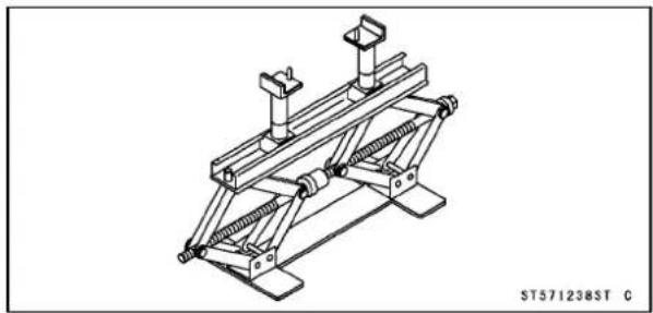
natural_image
Technical line drawing of a mechanical support structure (no text or symbols)EngineRemoval/Installation
EngineRemoval
- Placethejack[A]undertheframetolifttherearwheel[B]offtheground.
SpecialTool-Jack:57001-1238
- Squeezethebrakeleverslowlyandholditwithaband [A].
WARNING
Besuretoholdthefrontbrakewhenremovingthe engine,orthemotorcyclemayfallover.Itcould causeanaccidentandinjury.
- Draintheengineoil(seePeriodicMaintenancechapter).
- Remove:
SideCoversandSeat(seeFramechapter)
FuelTank(seeFuelSystemchapter)
- Disconnectthecablesandwiringleadsfromtheengine.
AlternatorLeadConnector[A]
EngineGroundLead[B]
ElectricStarterMotorCableTerminal[C]
SparkPlugCap
BreatherTube
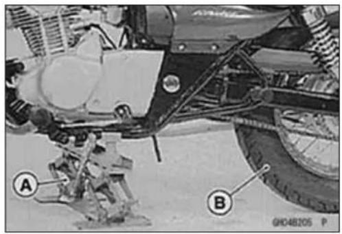

natural_image
Technical line drawing of a mechanical assembly with labeled component A (no text or symbols beyond label)
natural_image
Close-up of a car engine bay with visible components and a marked section (A), no readable text or symbols present.
natural_image
Mechanical assembly diagrams showing two views of a vehicle's engine components (no text or symbols visible)- Remove:
Muffler(seeEngineTopEndchapter)
CylinderHeadBracket[A]
CarburetorB
ShiftPedal(seeCrankshaft/Transmissionchapter)
ChainCoverandEngineSprocket(seeFinalDrivechapter)
ClutchCableLowerEnd(seeClutchchapter)

natural_image
Close-up of a mechanical assembly with labeled parts A and B, showing internal components and wiring (no readable text or symbols)7-6ENGINEREMOVAL/INSTALLATION
EngineRemoval/Installation
- Remove:
EngineMountingBolts[A]
EngineMountingBracketBolts[B]
○Pulloutthemountingboltswhileliftingtheengine.
- Liftuptheengineandmoveittotherightsideoftheframe.
- Removetheengine[A]fromthevehiclerightside.
Engine Installation
- Insertthemountingboltsfromtheleftsideoftheengine andinstallthenutsontherightside.
- Tightentheenginemountingboltswiththespecified torque.
Torque-EngineMountingBolts, Nuts(M10)[A]:44N·m (4.5kgf·m, 33ft·lb)
EngineMountingBolts, Nuts(M8)[B]:25N·m(2.5 kgf·m, 18ft·lb)
EngineMountingBracketBolts:25N·m(2.5 kgf·m,18ft·lb)
CylinderHeadBracketBolts, Nuts: 25N·m (2.5 kgf·m, 18ft·lb)
- Installthedrivechain[A]andenginesprocket[B].

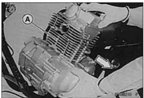
natural_image
Close-up of a mechanical assembly with labeled component A (no readable text or symbols)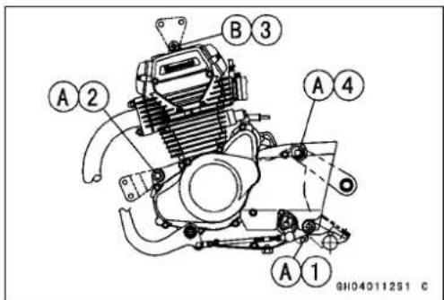

EngineRemoval/Installation
★ Iftheenginesprocketishardtoinstall,removethemaster linkandtheclipfromthedrivechain,andtheninstallthe enginesprocket.
○Installtheclip[A]sothattheopenend[B]ofthe"U"points intheoppositedirectionofchainrotation[C].
- Installtheenginegroundcable[A]asshown.Runthe cablenearthemountingboss[B].
- Tighten:
Torque-EngineGroundTerminalBolt:9.8N·m(1.0kgf·m, 87in·lb)


- Runthecables, hoses, and leads according to the Cable, Wire, and HoseRoutingsection of the Appendix chapter.
- Installtheremovedparts(seeappropriatechapters).
- Adjust:
ThrottleCable(seeFuelSystemchapter)
ClutchCable(seeClutchchapter)
DriveChain(seeFinalDrivechapter)
- Filltheenginewithengineoil(seeEngineLubrication Systemchapter).
- Adjusttheidlespeed(seeFuelSystemchapter).
- Checktheclutchoperation.
- Checkthebrakeeffectiveness.
WARNING
Donotattempttodrivethemotorcycleuntilafull brakeleverisobtainedbypumpingthebrakelever untilthepadsareagainstthedisc.Thebrakewill notfunctiononthefirstapplicationoftheleverif thisisnotdone.
WARNING
If a full brake pedal is not obtained, disassemble and inspect the brake parts. Worn part scan cause lock of the brake or loss of braking.
Crankshaft/Transmission
TableofContents
ExplodedView....8-2
Specifications....8-6
SpecialToolsandSealant......8-7
Crankcase....8-8
CrankcaseDisassembly......8-8
CrankcaseAssembly......8-9
Crankshaft....8-13
CrankBalancerGear Removal/Installation....8-13
CrankshaftRemoval......8-13
CrankshaftInstallation......8-13
CrankshaftDisassembly......8-13
ConnectingRodBigEnd Seizures....8-13
ConnectingRodBigEndRadial Clearance....8-13
ConnectingRodBigEndSide Clearance....8-13
CrankshaftRunout......8-13
BalancerShaftGear....8-15
BalancerShaftGearRemoval.....8-15
BalancerShaftGearInstallation..8-15
StarterMotorClutch....8-16
StarterMotorClutch Removal/Installation....8-16
StarterMotorClutchDisassembly8-16
StarterMotorClutchAssembly....8-16
StarterMotorClutchInspection...8-16
TorqueLimiterInspection......8-16
ExternalShiftMechanism......8-17
ShiftPedalHeightAdjustment.....8-17
ShiftPedalRemoval....8-17
ExternalShiftMechanism Removal....8-17
ExternalShiftMechanism Inspection......8-18
Transmission....8-19
TransmissionShaftRemoval......8-19
TransmissionShaftInstallation....8-19
TransmissionDisassembly...... 8-19
TransmissionAssembly......8-20
ShiftDrumRemoval/Installation... 8-21
ShiftForkBending.... 8-21
ShiftFork/GearGrooveWear..... 8-21
ShiftForkGuidePin/Drum GrooveWear.... 8-21
GearDogandGearDogHole Damage.... 8-21
BallBearing,andOilSeal.... 8-22
BallBearingReplacement...... 8-22
BallBearingWear.... 8-22
OilSealInspection 8-22
8-2CRANKSHAFT/TRANSMISSION
ExplodedView
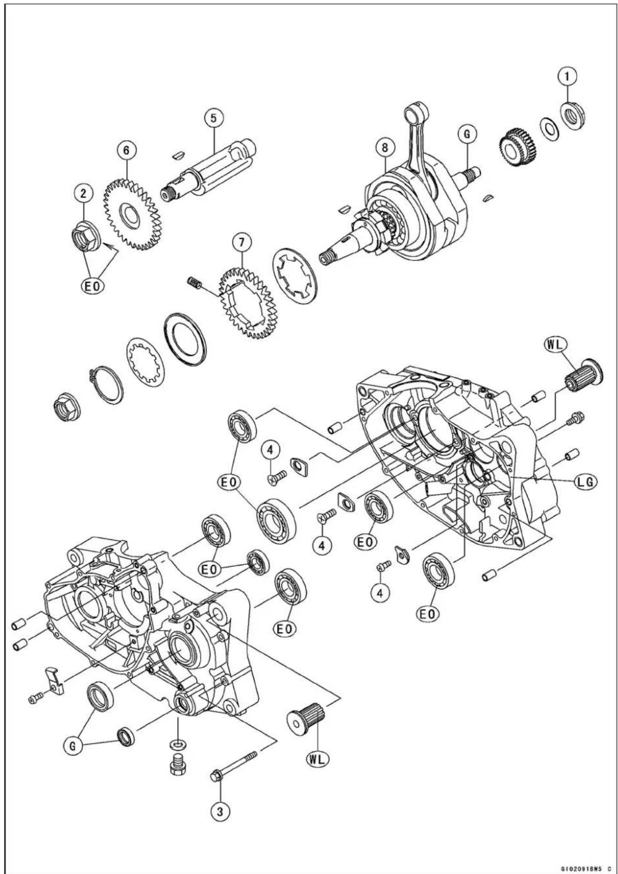
ExplodedView
| No.Fastener | Torque | Remarks | |||
| N·mkgf | mft·lb | ||||
| 1PrimaryGearNut697.051 | |||||
| 2BalancerShaftGearNut788.058EO | |||||
| 3 | CrankcaseBolts | 8.80.90 | 78in·lb | ||
| 4 | Crankcase Bearing Retainer Screws | 4.9 | 0.50 | 43 in·lb | |
- BalancerShaft
- Balancershaft gear
- Crankbalancer gear
- Crankshaft
EO: Applyengine oil.
G: Apply grease.
LG: Applyliquid gasket.
WL: Applysoapandwater solution.
ExplodedView

ExplodedView
| No.Fastener | Torque | Remarks | |||
| N·mkgf | mft·lb | ||||
| 1NeutralSwitch151.511 | |||||
| 2ShiftDrumCamScrew4.90.5043in·lbL | |||||
| 3 | GearSetLeverNut | 111.1 | 95in·lb | ||
| 4 | Engine Sprocket Holder Bolts | 12 | 1.2 | 104 in·lb | |
| 5 | Shift Shaft Return Spring Pin | 29 | 3.0 | 21 | L |
| 6 | Shift Lever Clamp Bolt | 12 | 1.2 | 104 in·lb | |
| 7 | Shift Pedal Nut | 30 | 3.1 | 22 | |
EO: Applyengineoil.
G: Applygrease.
L: Applyanon-permanentlockingagent.
M: Applymolybdenumdisulfidegrease.
R: ReplacementParts
Specifications
| ItemStandardServiceLimit | ||
| Crankshaft,ConnectingRodConnectingRodBigEndSide ClearanceConnectingRodBigEndRadial ClearanceCrankshaftRunoutTIR0.03mm(0.0012in.)orlessTIR0.07mm | 0.5 mm (0.020 in.)0.07 mm (0.003 in.)(0.003in.) | |
| TransmissionShift Fork Ear ThicknessGear Shift Fork Groove WidthShift Fork Guide Pin DiameterShift Drum Groove Width | 4.9 ~ 5.0 mm (0.193 ~ 0.197 in.)5.05 ~ 5.15 mm (0.199 ~ 0.203 in.)5.9 ~ 6.0 mm (0.232 ~ 0.236 in.)6.05 ~ 6.20 mm (0.238 ~ 0.244 in.) | 4.8 mm (0.189 in.)5.25 mm (0.207 in.)5.8 mm (0.228 in.)6.3 mm (0.248 in.) |
SpecialToolsandSealant
OutsideCirclipPliers: 57001-144
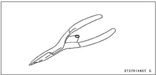
natural_image
Line drawing of a pair of pliers (no text or symbols on the diagram itself)GearHolder,m1.75: 57001-1015

natural_image
Technical line drawing of a mechanical gear assembly (no text or symbols)BearingDriverSet: 57001-1129

natural_image
Isometric line drawing of a box containing multiple circular components, no text or symbols presentCrankshaftJig: 57001-1174

natural_image
Technical line drawing of a mechanical clamp or bracket component (no text or symbols)CrankcaseSplittingToolAssembly: 57001-1362

natural_image
Technical line drawing of a mechanical clamp or bracket assembly with four pins and bolts (no text or symbols)KawasakiBond(LiquidGasket-Silver): 92104-002

8-8CRANKSHAFT/TRANSMISSION
Crankcase
CrankcaseDisassembly
- Remove:
Clutch(seeClutchchapter)
PrimaryGear(seeClutchchapter)
StarterMotor(seeElectricalSystemchapter)
Alternator(seeElectricalSystemchapter)
BalancerShaftGear(seeBalancerShaftGearRemoval)
CrankBalancerGear(seeEngineTopEndchapter)[A]
- Removetheengine(seeEngineRemoval/Installation chapter).
- Settheengineonacleansurfaceandholdtheengine steadywhilepartsarebeingremoved.
★Ifthecrankshaftistoberemoved,removethefollowing.
CamshaftChain(seeEngineTopEndchapter)
CylinderHead(seeEngineTopEndchapter)
CylinderandPiston(seeEngineTopEndchapter)
- Removetheexternalshiftmechanism(seeExternalShift MechanismRemoval).
- Removetheallcrankcasebolts[A]fromtheleftsideof thecrankcase.
- Removetheoutputshaftsleeve[A]andO-ring[B].
○DonotreusetheremovedO-ring.
- Screwthecrankcasesplittingtool[A]intotheleftsideof thecrankcase[B].Becertaintoscrewtheadaptersinall theway.
SpecialTool-CrankcaseSplittingToolAssembly:57001-1362
- Tightenthecenterboltofthecrankcasesplittingtoolto splitthecrankcase.
○Removetheleftcrankcasehalf.

natural_image
Mechanical gear assembly with labeled component A, no visible text or symbols
natural_image
Mechanical gear assembly diagram showing interconnected components (no text or labels visible)

Crankcase
- Removethetransmissionshaft[A], gearsandbalancer shaftfromtherightcrankcasehalf[B].
- Remove: ShiftDrumCamScrew[A] ShiftDrumCam[B] WoodruffKey[C] ShiftDrum[D] GearSetLeverE
- Supporttherightcrankcasehalf[A]withasuitablere-tainer.
- Removethecrankshaft[B]fromtherightcrankcasehalf usingapress.
CAUTION
Donotremovetheballbearingsandtheoilseals unlessitisnecessary.Iftheyareremoved,replace themwithnewones.
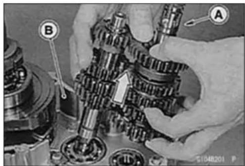

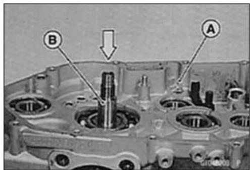
CrankcaseAssembly
CAUTION
Rightandleftcrankcasehalvesaremachinedatthe factoryintheassembledstate,soifreplaced,they mustbereplacedasaset.
- Applysoapandwatersolutionaroundtheengine damper [A]beforepressingitintothecrankcase.

natural_image
Technical line drawing of a mechanical assembly with labeled component A (no text or symbols beyond label)CAUTION
Donotapplyengineoiltopreventrubberdamper deterioration.
Crankcase
- Pressthedamper[A]intothecrankcasewiththebearing drierset.
SpecialTool-BearingDriverSet:57001-1129

natural_image
Technical line drawing of a mechanical assembly with no visible text or symbols- Chipofftheoldgasketfromthematingsurfacesofthe crankcasehalvesandcleanthemoffwithahigh-flash pointsolvent.
- Usingcompressedair, blowout the oil passages in the crankcase halves.
WARNING
Cleantheenginepartsinawell-ventilatedarea,and takecarethattherearenosparksorflameany-whereneartheworkingarea;thisincludesanyappliancewithapilotlight.Donotusegasolineora low-flashpointsolventtocleanparts.Afireorexplosionscouldresult.
- Supportthecrankcasebearingbosswithasuitableretainer[A].
- Usingapressandthebearingdriverset[C],installnew bearings[B]untiltheybottomsout.
SpecialTool-BearingDriverSet:57001-1129
CAUTION
Supportthecrankcasebearingbosswhenthebearingsarepressed,orthecrankcasecouldbedamaged.
- Presstheoutputshaftbearing[A]inthelleftcrankcase half[B]sothatthesealedside[C]facestotheoilseal.
SpecialTool-BearingDriverSet:57001-1129
- Tightenthebearingretainingscrewssecurelyintheright crankcasehalf.
Torque-BearingRetainingScrews:4.9N·m(0.50kgf·m,43in·lb)
- Puttheoutputshaftoilseal[D]in, beingcarefulofthe properdirectionasshown.


G104D90BS1 C
Crankcase
- Usingcompressedair[A], blowout the oil passage in the right crankshaft[B].
- Positioningtheconnectingrod[A]bigendatBDC,putin thecrankshaftjig[B]betweenthecrankshaftflywheels.
- Pressthecrankshaft[C]intherightcrankcasehalf[D]. SpecialTool-CrankshaftJig:57001-1174
- Applyengineoiltothetransmissiongears, bearings, shift forks, shiftdrumandcrankshaftbearing.
- Install: ShiftDrum[A] TransmissionShafts[B] ShiftForks[C] BalancerShaftD
- Checkthattheshiftdrumisinneutralposition.
- Checkthattwodowelpins[A]areinplaceoftheright crankcasehalf.
- Applyliquidgaskettothematingsurface[B]oftheleft crankcasehalf.
Sealant-KawasakiBond(LiquidGasket-Silver):92104-002 - Usingasuitabletoolontheleftcrankcasetopressaround theholeforthecrankshaft,fitthecrankcasehalvestogetherwithapressonthetool.
- Removethecrankshaftjig.
- Installthecrankcasebolts[A]inthelleftcrankcasehalf [B]andtightenthem,startingwiththenearestonestothe crankshaft,thenfartherones.
Torque-CrankcaseBolts:8.8N·m(0.90kgf·m,78in·lb)

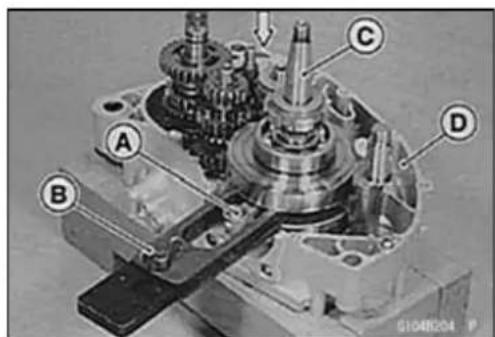

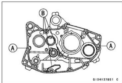
8-12CRANKSHAFT/TRANSMISSION
Crankcase
- Checktoseethatthecrankshaft,driveshaft,andoutput shaftallturnfreely(intheneutralposition).
★Ifthecrankshaftwillnotturn,probablythecrankshaftis notcentered;Tapthemountportion[A]ofthecrankcase withaplastichammertorepositionit.
- Puttheendofthewoodruffkey[A]intotheinsideofthe ballbearing[B]sothatthekeycanseatsecurely.
- Applyanon-permanentlockingagenttotheshiftdrum camscrew[A]andtightenit. Torque-ShiftDrumCamScrew:4.9N·m(0.50kgf·m,43 in·lb)
- Installthegearsetlever[B]andtightenthenut[C]. Torque-GearSetLeverNut:11N·m(1.1kgf·m,95in·lb) - InstalltheexternalshiftmechanismD.
- Checktoseethatgearsshiftsmoothlyfrom1stto5th gear,and5thto1stwhilespinningtheoutputshaft. - Settheshiftdrumintheneutralposition.
- Replace the O-ring [A] on the output shaft with anewone. - Apply greasetothe inside of the output shaft collar [B]. - Insert the collar with the oil groove end [C] facing in. - Install theremoved parts (see appropriate chapters).

natural_image
Mechanical assembly diagram showing interconnected gears and housing (no text or labels visible)


Crankshaft
CrankBalancerGearRemoval/Installation
- RefertoCamshaftChainRemoval/InstallationintheEngineTopEndchapter.
CrankshaftRemoval
- RefertotheCrankcaseDisassemblyinthischapter.
CrankshaftInstallation
- RefertotheCrankcaseAssemblyinthischapter.
CrankshaftDisassembly
Ifthecrankshaftisdamaged,replaceitasaset.Notfor saletoeachpartofthecrankshaft.
ConnectingRodBigEndSeizures
- Incaseofseizure, replacethecrankshaftassembly.
ConnectingRodBigEndRadialClearance
- Supportthecrankshaftwithbothside,andplaceadial gauge[A]againsttheconnectingrodbigend.
- Push[B]theconnectingrodfirsttowardsthegaugeand thenintheoppositedirection. Thedifferencebetween twogaugereadingsisteradialclearance.
ConnectingRodBigEndRadialClearance
Standard: 0.005 \~ 0.017 mm (0.0002 \~ 0.0007 in.)
ServiceLimit:0.07mm(0.003in.)
★ Iftheradialclearanceexceedstheservicelimit,replace thecrankshaftassembly.
ConnectingRodBigEndSideClearance
- Measureconnectingrodbigendsideclearance[A].
ConnectingRodBigEndSideClearance
Standard: 0.20 \~ 0.35 mm (0.008 \~ 0.014 in.)
ServiceLimit:0.50mm(0.020in.)
★ Iftheclearanceexceedstheservicelimit,replace the crankshaftassembly.
CrankshaftRunout
- Supporting the crankshaft from both side, placeadial gauge as shown and turn the crankshaft slowly. The maximum difference in gaugereading is the crankshaft runout.
Standard: TIR0.03mm(0.0012in.) or less
ServiceLimit: TIR0.07mm(0.003in.)
★ Iftherunoutateeitherpointexceedstheservicelimit,replace the crankshaft assembly with a new one or align the crankshaftsothattherunoutfallswithintheservicelimit.


8-14CRANKSHAFT/TRANSMISSION
Crankshaft
- Firstcorrectthehorizontalmisalignmentbystrikingthe projectingcrankhalf[A]withaplastic,softlead,orbrass hammerasshown.
- Rechecktherunoutwithadialgaugeandrepeatthe processuntiltherunoutfallswithintheservicelimit.
- Next, correct the vertical misalignment by either driving a wedge[A] in between the crank halves or by squeezing them in advice, depending on the nature of them misalignment.
CAUTION
Donothammerthecrankhalfatthepoint[B].


BalancerShaftGear
BalancerShaftGearRemoval
- Remove:
AlternatorRotor(seeElectricalSystemchapter) ClutchCover(seeClutchchapter)
- Using the gearholder, hold the primary gear [A] and loosenthe balancershaft gear nut [B].
SpecialTool-GearHolder,m1.75:57001-1015[C]
- Removethebalancershaftgear[D]alongwiththe woodruffkey.
BalancerShaftGearInstallation
- Fitthewoodruffkey[A]securelyintothegroove,then installthebalancershaftgear[B].
- Alignthetimingmarks[A]onthebalancershaftgearand thecrankbalancergear. BalancerShaftGearNut[B]
- Using the gearholder, hold the primary gear [A]asshown.
- Applyoiltothethreadsandseatingsurfaceofthebalancershaftgearnut.
- Tightenthebalancershaftgearnut[B].
Torque-BalancerShaftGearNut:78N·m(8.0kgf·m,58 ft·lb)
SpecialTool-GearHolder,m1.75:57001-1015
- Install:
AlternatorRotor(seeElectricalSystemchapter) AlternatorCover(seeElectricalSystemchapter) ClutchCover(seeClutchchapter)
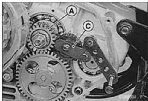
natural_image
Mechanical gear assembly with labeled components (A, C), no visible text or symbols beyond labels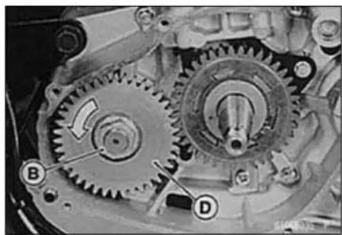
natural_image
Mechanical gear assembly diagram showing two meshed gears with labeled components (B and D), no readable text or symbols present.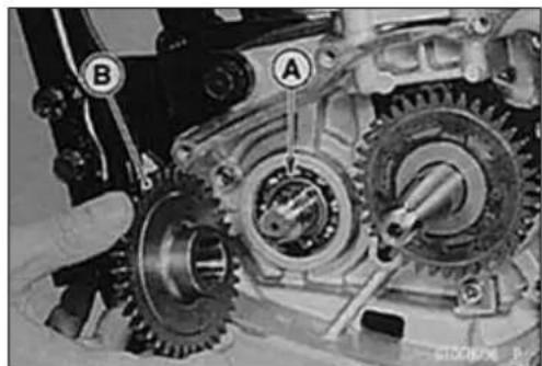
natural_image
Mechanical gear assembly diagram showing interconnected gears and shafts (no text or symbols visible)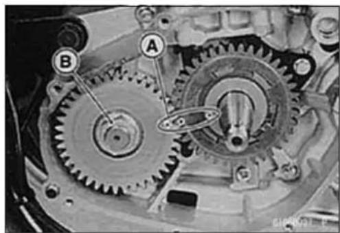
natural_image
Mechanical gear assembly diagram showing two interconnected gears labeled A and B (no text or symbols beyond labels)
natural_image
Mechanical gear assembly diagram showing two interconnected gears labeled A and B (no text or symbols beyond labels)8-16CRANKSHAFT/TRANSMISSION
StarterMotorClutch
StarterMotorClutchRemoval/Installation
- RefertotheAlternatorRotorRemovalandInstallationin theElectricalSystemchapter.
StarterMotorClutchDisassembly
- RemovethealternatorrotorA.
- Holdthealternatorrotorwiththeflywheelholder[B]and removethestartermotorclutchbolts[C].
SpecialTool-FlywheelHolder:57001-1313 - Removetheartermotorclutch[D].
StarterMotorClutchAssembly
- Applyanon-permanentlockingagenttothethreadsof thestartermotorclutchbolts[A], andtightenthem.
Torque-StarterMotorClutchBolts
(BN125-A1):34N·m(3.5kgf·m,25ft·lb)
(BN125-A2\~):12N·m(1.2kgf·m,104in·lb)
StarterMotorClutchInspection
- Removethealternatorcover(seeElectricalSystemchapter).
- Turnthestartergear[A]byhand. Thestartergearshould turnclockwise[B]freely, but should not turncounterclockwise[C]by the starterclutch function.
★ Ifthestartermotorclutchdoesnotoperateasitshould orifitmakesnoise,disassemblethestartermotorclutch, andvisuallyinspecttheclutchparts.Ifthereisanyworn ordamagedpart,replaceit. - Visuallyinspectthestartergearandcrankshaft.
★ Iftheslidingsurface[A]iswornordamaged,replace the startergearand/orcrankshaft.
TorqueLimiterInspection
- Removethetorquelimiter[A]andvisuallyinspectit.
★ Ifthelimiterhasanywear, discoloration, orotherdamage, replaceitasaunit.
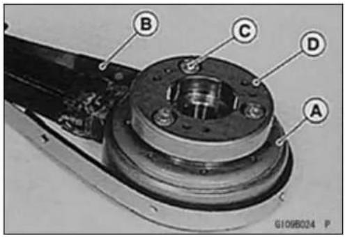

natural_image
Mechanical gear assembly with labeled components (A, B, C), no readable text or symbols beyond labels
natural_image
Mechanical gear assembly diagrams showing two views of a shaft and rotor components (no text or symbols)
natural_image
Close-up of mechanical components with no visible text or symbolsExternalShiftMechanism
ShiftPedalHeightAdjustment
- Adjustthelengthoftheshiftlinkagerodsothatthedistancebetweentheshiftpedal[A]andthefrontleftfootpeg [B] shall be 26.5 \~ 29.5 mm (1.04 \~ 1.16 in.) [C]. Then, thelength[D]oftheshiftlinkagerodwillbeapproximately 141mm(5.55in.)asillustrated.
ShiftPedalRemoval
- RemovetheenginesprocketcoverA.
- Removetheclampbolt[B].
- Removetheshiftlever[C]fromtheshiftshaft.
NOTE
Wheninstallingtheshiftleverontotheshiftshaft, align thegrooveoftheleverwiththepunchmarkoftheshift shaft.
- Remove: Bolts[A] FrontLeftFootpeg[B] ShiftPedal[C]
- Remove: Nut[A] ShiftPedal[B]
ExternalShiftMechanismRemoval
- Draintheengineoil(seeEngineLubricationSystem chapter).
- Remove: Clutch(seeClutchchapter) EngineSprocketCover(seeFinalDrivechapter)
- Unscrewtheshiftleverclampboltandremovetheshift leverfromtheshiftshaft.

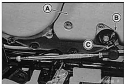

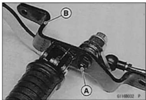
8-18CRANKSHAFT/TRANSMISSION
ExternalShiftMechanism
- Turntheshiftdrumandpositiontheneutralgroove[A]as shown.
- Removetheshiftshaft[D]whilepushing[C]theshift mechanismarm[B]towardtheshaft.
ExternalShiftMechanismInspection
-
Examinetheshiftshaft[A]foranydamage.
★Iftheshaftisbent, straightenorreplaceit.
★Ifthesplines[B]aredamaged,replacetheshaft.
★Ifthesprings[C][D]aredamagedinanyway,replace them.
★IftheshiftpawlEisdamagedinanyway,replace the shiftshaftassembly. -
Checkthereturnspringpin[A]isnotloose.
★Ifitisloose,unscrewittoapplyanon-permanentlocking agenttothethreads,andtightenit.
Torque-ShiftShaftReturnSpringPin:29N·m(3.0kgf·m, 21ft·lb)
- Check the gear positioning lever [B], and their spring [C] for breaksordistortion.
★Iftheleverorspringsaredamagedinanyway,replace them. - Visuallyinspecttheshiftdrumcam[D].
★ Ifthecamisbadlywornorifitshowsanydamage,replace it.
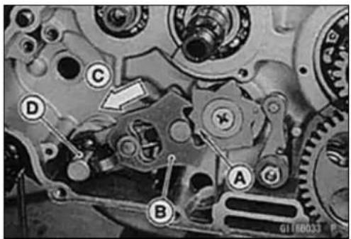
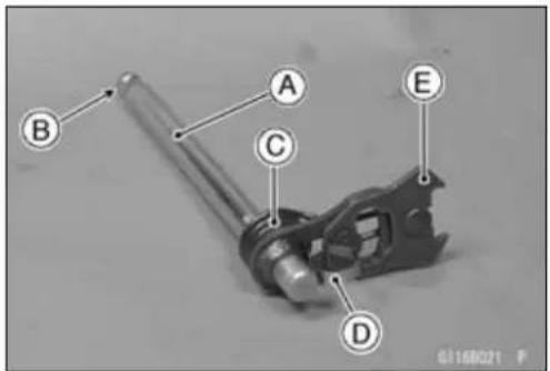

Transmission
TransmissionShaftRemoval
- Splitthecrankcase(seeCrankcaseDisassembly).
- Pullouttheshiftrod[A]allowingtheshiftforkguidepins tofreefromtheshiftdrum[B].
- Removetheshiftforks[C].
- Removetheshiftdrum.
- Pulloutthedriveshaft[D]andoutputshaftEtogether withtheirgearsmeshed.
TransmissionShaftInstallation
- Applyengineoiltotheslidingportionsofeverygearand bearing.
-
Installthedriveshaftandoutputshaft[B]intheright crankcasewiththeirgears[A]meshed.
-
Applyasmallamountofengineoiltotheshiftforkfingers andfiteachshiftforkintothegrooveofthepropergear.
- Theshiftforkscanbeidentifiedbytheirshapeornumber.Installthemnotingthedirectionshown.
○ Thedriveshaftfork[A]istheshortest, and installit with itsmark "65"[B]facingtheengineleftside.
○ Installtheoutputshaftfork[C]withitsmark"64"[D]facing theengineleftside.
○InstalltheleftoutputshaftforkEasshown. - Fiteachshiftforkguidepinintothecorrespondinggroove intheshiftdrum.
- Applyasmallamountofengineoiltotheshiftrodand slidethemintotheshiftforks.
- Assemblethecrankcase(seeCrankcaseAssembly).
TransmissionDisassembly
- Removethetransmissionshafts.
- Removethecirclips, washers, thengears.
SpecialTool-OutsideCirclipPliers:57001-144[A] - Donotreusetheremovedcirclips.
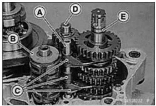

natural_image
Close-up of hands assembling a mechanical gear assembly (no visible text or symbols)

natural_image
Close-up of a mechanical component with a labeled section A, showing interlocking gears and a shaft (no text or symbols beyond label)Transmission
TransmissionAssembly
- Replaceanycirclipsremovedwithnewones.
○Installthecirclips[A]sothattheopening[B]isaligned with asplinegroove[C].
○Installthetoothedwasher[D]sothattheteethEarenot alignedwiththeopeningofthecirclip.
- Thedriveshaftgearscanberecognizedbysize:thegear withthesmallestdiameteris1stgear,andthelargestone is5thgear.Besurethatallpartsareputbackinthecorrectsequenceandallcirclipsandwashersareproperlyin place.
- Theoutputshaftgearscanberecognizedbysize:the gearwiththelargestdiameteris1stgear,andthesmall-estoneis5thgear.Besurethatallpartsareputback inthecorrectsequenceandallcirclipsandwashersare properlyinplace.
- Checkthateachgearspinsorslidesfreelyonthetransmissionshaftswithoutbindingafterassembly.


1.Circlip
2.Circlip
3.Washer
- Toothed Washer
5.DriveGear-2nd
6.Collar
7.DriveGear-3rdand4th
8.DriveGear-5th
9.DriveShaft
- OutputGear-2nd
11.OutputGear-4th
12.OutputGear-3rd
13.OutputGear-5th
-
OutputGear-Low
-
OutputShaft
Transmission
ShiftDrumRemoval/Installation
- RefertotheCrankcaseDisassembly/Installationinthe Crankshaft/Transmissionchapter.
ShiftForkBending
- Visuallyinspecttheshiftforks, and replaceanyforkthatis bent. Abentforkcouldcauseddifficultyinshifting, orallow thetransmissiontojumpoutofgearwhenunderpower. 90°[A]
ShiftFork/GearGrooveWear
- Measurethethicknessoftheshiftforkears[A], and measurethewidth[B]ofthegeargrooves.
ShiftForkEarThickness
Standard: 4.9 \~ 5.0 mm (0.193 \~ 0.197 in.)
ServiceLimit:4.8mm(0.189in.)
GearGrooveWidth
Standard: 5.05 \~ 5.15 mm (0.199 \~ 0.203 in.)
ServiceLimit: 5.25mm(0.207in.)
★ Ifthethicknessofashiftforkearislessthantheservice limit, theshiftforkmustbereplaced.
★ If the gear groove is worn over the service limit, the gear must be replaced.
ShiftForkGuidePin/DrumGrooveWear
- Measurethediameterofeachshiftforkguidepin[A], and measurethewidth[B]ofeachshiftdrumgroove.
ShiftForkGuidePinDiameter
Standard: 5.9 \~ 6.0 mm (0.232 \~ 0.236 in.)
Service Limit: 5.8 mm (0.228 in.)
ShiftDrumGrooveWidth
Standard: 6.05 \~ 6.20 mm (0.238 \~ 0.244 in.)
ServiceLimit: 6.3mm(0.248in.)
★ Iftheguidepinonanyshiftforkislessthantheservice limit, theforkmustbereplaced.
★ Ifanyshiftdrumgrooveiswornovertheservicelimit, the drummustbereplaced.
GearDogandGearDogHoleDamage
- Visuallyinspectthegeardogs[A]andgeardogholes[B].
★Replaceanydamagedgearsorgearswithexcessively worndogsordogholes.


natural_image
Technical line drawing of two mechanical components labeled A and B, showing assembly details without any text or symbols.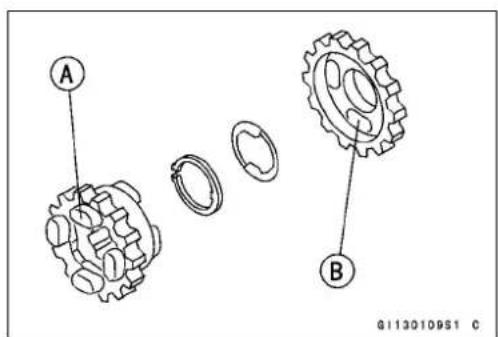
8-22CRANKSHAFT/TRANSMISSION
BallBearing, and Oil Seal
BallBearingReplacement
CAUTION
Donotremovetheballbearingsunlessitisnecessary.Removalmaydamagedthem.
- Usingapressorpuller,removetheballbearing.
NOTE
○ Intheabsenceoftheabovementionedtools, satisfactoryresultsmaybeobtainedbyheatingthecasetoapproximately93°C(200°F)max,andtappingthebearinginorout.
CAUTION
Donotheatthecasewithatorch. This will warp the case. Soakthecaseinoilandheattheoil.
- Usingapressandthebearingdriverset[A],installthe newbearinguntilitstopsatthebottomofitshousing. SpecialTool-BearingDriverSet:57001-1129

BallBearingWear
CAUTION
Donotremovethebearingsforinspection. Removalmaydamagethem.
- Checktheballbearings.
○Sincetheballbearingsaremadetoextremelyclosetolerances,thewearmustbejudgedbyfeelratherthanmeasurement.Cleaneachbearinginahigh-flashpointsolvent,dryit(donotspinthebearingwhileitisdry),andoil itwithengineoil.
○Spin[A]thebearingbyhandtocheckitscondition.
★ Ifthebearingisnoisy, does not spinsmoothly, or has any roughspots, replace it.
OilSealInspection
- Inspecttheoilseals.
★Replaceitifthelipsaremisshapen,discolored(indicating thattherubberhasdeteriorated),hardenedorotherwise damaged.
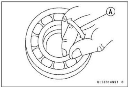
Wheels/Tires
TableofContents
Exploded View.... 9-2
Specifications 9-4
Special Tools 9-5
Wheels (Rims) 9-6
Front Wheel Removal 9-6
Front Wheel Installation 9-6
Rear Wheel Removal 9-7
Rear Wheel Installation.... 9-8
Wheel Inspection 9-9
Spoke Inspection 9-9
Rim Inspection 9-9
Axle Inspection.... 9-9
Tires 9-10
Air Pressure Inspection/Adjustment 9-10
Tire Inspection 9-10
Tire Removal 9-10
Tire Installation.... 9-11
Hub Bearings (Wheel Bearings) 9-12
Removal.... 9-12
Installation.... 9-12
Inspection.... 9-13
Lubrication 9-13

ExplodedView
| No.Fastener | Torque | Remarks | |||
| N·m | kgf·mft·lb | ||||
| 1 | Tire Air Valve Nuts | 1.5 | 0.15 | 13 in·lb | |
| 2 | Spoke Nipples | 2.0 ~ 3.9 | 0.20 ~ 0.40 | 17 ~ 35 in·lb | |
| 3 | Front Axle Nut | 78 | 8.0 | 58 | |
| 4 | Rear Axle Nut | 98 | 10.0 | 72 | |
- For DE of BN125-A1 \~ A2 and On and after BN125-A3 of EUR Models
G: Applygrease.
R: ReplacementParts
WL: Applysoapandwatersolutionorrubberlubricant.
DE: Germany
EUR: Europe
Specifications
| ItemStandardServiceLimit | ||
| Wheels(Rims)RimSize:Front17×1.85--Rear15×2.75--RimRunout(withtireinstalled):AxialTIR0.8mm(0.03in.)orless2mm(0.08in.)RadialTIR1.0mm(0.04in.)orless2mm(0.08in.)Axle Rumout/100 mm (3.9 in.) | TIR 0.1 mm (0.004 in.) or less | 0.2 mm (0.008 in.) |
| TiresAirPressure(WhenCold):Front:(BN125-A1 ~ A2)(BN125-A3 ~)Rear:(BN125-A1 ~ A2)(BN125-A3 ~) | Up to 185 kg (408 lb) load: 150 kPa (1.5 kgf/cm2,21psi)Up to 155 kg (342 lb) load: 150 kPa (1.5 kgf/cm2,21psi) | --- |
| Up to 185 kg (408 lb) load: 175 kPa (1.75kgf/cm2,25psi)Up to 155 kg (342 lb) load: 175 kPa (1.75kgf/cm2,25psi) | --- | |
| TreadDepth:Front:(BN125-A1~A2)4.5mm(0.18in.)BN125-A3 ~ A5)(BN125-A6 ~)Rear: | 4.0 mm (0.157 in.)4.1 mm (0.161 in.) | 1 mm (0.04 in.) |
| 7.3mm(0.29in.) | 2mm(0.08in.) | |
| StandardTires:Front:(BN125-A1 ~ A2)(BN125-A3 ~ A5)(BN125-A6 ~)Rear:(BN125-A1 ~ A2)(BN125-A3 ~) | Make, Type | Size |
| DUNLOP D404F, tube typeIRC NF53 Tube typeIRC NF53 Tube type | 90/90 -17 49P90/90-17 49P90/90 -17 M/C 49P | |
| DUNLOP D404, tube typeIRC NR67 Tube type | 130/90-15 M/C 66P130/90 -15 M/C 66P | |
| Replacement Tires:FrontRear | Make, Type | Size |
| METZELER PERFECT ME77, tube typeMETZELER PERFECT ME77, tube type | 3.00-1750P130/90-15 M/C 66S | |
WARNING
Usethesamemanufacture'stiresonbothfrontandrearwheels.
SpecialTools
RimProtector: 57001-1063

natural_image
Technical line drawing of six curved metal tools or clips (no text or symbols)BeadBreakerAssembly: 57001-1072

natural_image
Line drawing of a manual pliers tool (no text or symbols present)BearingDriverSet: 57001-1129

natural_image
Isometric line drawing of a box containing multiple circular components, no text or symbols presentJack: 57001-1238

natural_image
Technical line drawing of a mechanical support structure (no text or symbols)BearingRemoverShaft,9: 57001-1265

natural_image
Line drawing of a mechanical tool or tool with a long handle and flange (no text or symbols)BearingRemoverHead,15 ^17 : 57001-1267
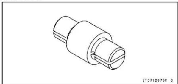
natural_image
Technical line drawing of a mechanical connector or fitting (no text or symbols)Wheels(Rims)
FrontWheelRemoval
- Removethecotterpinandaxlenut[A].
- Removethespeedometercablelowerend[B].
- Raisethefrontwheel[B]offthegroundusingthejack[A]. SpecialTool-Jack:57001-1238
- Pullouttheaxleanddropthefrontwheel[A]outofthe forks. - Insertawoodenplatebetweenthepadsinthecaliperto preventthecaliperpistonfromjumpingout.
CAUTION
Donotlaythewheeldownonthedisc. This can damageorwarpthedisc. Placeblocksunderthe wheelsothatthediscdoesnottouchtheground.
FrontWheelInstallation
- Applygreasetotheseallip[A]ofthespeedometergear.
- Installthespeedometergearhousingsothattheprojections[C]fitinthedrivenotches[B].
• Fitthecollar[A]ontherightsideofthehub.
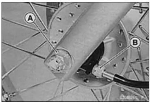
natural_image
Close-up of mechanical components with labeled parts A and B, no readable text or symbols present.

natural_image
Close-up of a motorcycle wheel with visible tire, disc, and mounting bracket (no text or symbols)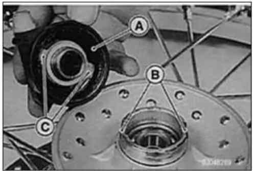
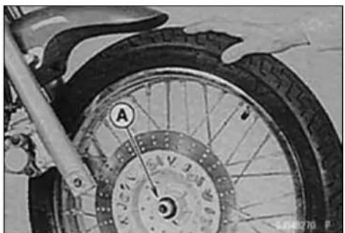
natural_image
Close-up of a motorcycle wheel with labeled component A, showing tread pattern and mounting bracket (no readable text or symbols beyond labels)Wheels(Rims)
- Fittheforklegstop[A]betweenthespeedometergear housingstop[B]andinstallthefrontwheel.
• Installtheaxlefromtherightsideandtightentheaxlenut.
Torque-FrontAxleNut:78N·m(8.0kgf·m,58ft·lb)
- Insertanewcotterpin[A].
NOTE
When inserting the cotterpin, if the slots in thenut do not align with the cotterpinhole in the axle, tighten the nut clockwise [B] uptonextalignment.
○Itshouldbewithin30degree.
○Loosenonceandtightenagainwhentheslotgoespast thenaresthole.
- Bendthecotterpin[A]overthenut[B].

natural_image
Close-up of mechanical components with labeled parts A and B, no readable text or symbols present

- Checkthefrontbrakeeffectiveness.
WARNING
Donotattempttodrivethemotorcycleuntilafull brakeleverisobtainedbypumpingthebrakelever untilthepadsareagainstthedisc.Thebrakewill notfunctiononthefirstapplicationoftheleverif thisisnotdone.
RearWheelRemoval
- Raisetherearwheel[B]offthegroundusingthejack[A]. SpecialTool-Jack:57001-1238

9-8WHEELS/TIRES
Wheels(Rims)
- Remove:
ChainCover
CotterPin[A]andAxleNut[B]
TorqueLinkBolt, Nut(rear)[C]
BrakeAdjustingNut[D]
- RemovethebrakerodEfromthebrakecamlever[F].
- Removethedrivechain[A]fromtherearsprocket,then removetherearwheel[B]totherear.

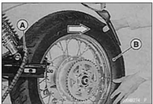
RearWheelInstallation
- Applyhigh-temperaturegreaseseallipsandtheinnercircumferenceofthesprocketcoupling(seeFinalDrivechapter).
• Installthecollar[A]onthebothsideofthehub. - Engagethedrivechainwiththerearsprocket, and install therearwheel.
- Checkthedrivechainslack(seePeriodicMaintenance chapter).
- Tighten:
Torque-RearAxleNut:98N·m(10.0kgf·m,72ft·lb)
- Insertanewcotterpin[A].
NOTE
When inserting the cotterpin, if the slots in then the nut align with the cotterpin hole in the axle, tighten the nut clockwise [B] uptonextalignment.
○ Itshouldbewithin30degree.
○ Loosenonceandtightenagainwhentheslotgoespast thenaresthole.

Wheels(Rims)
- Bendthecotterpin[A]overthenut[B].
- Adjustthebrakepedalfreeplay(seeBrakeschapter).
- Checktherearbrakeeffectiveness.
WARNING
Ifafullbrakepedalisnotobtained,disassemble andinspectthebrakeparts.Wornpartscauselock ofthebrakeorlossofbraking.
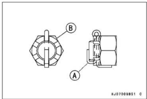

natural_image
Close-up of mechanical components with labeled parts (A), no readable text or symbols presentWheelInspection
- Raisethefront/rearwheelofftheground.
SpecialTool-Jack:57001-1238
- Spinthewheellightly, and check for roughnessor binding.
★ Ifroughnessorbindingisfound, replacethehubbearings.
SpokeInspection
- RefertotheSpokeTightnessInspectioninthePeriodic Maintenancechapter.
RimInspection
- RefertotheRimRunoutInspectioninthePeriodicMaintenancechapter.
AxleInspection
- Visuallyinspectthefrontorrearaxlefordamage.
★ Iftheaxleisdamagedorbent,replaceit. - PlacetheaxleontheVblocksthatare100mm(3.9in.) [A]apart, andsetadialgauge[B]ontheaxleatapoint halfwaybetweentheblocks. Turn[C]theaxletomeasure therunout. Thedifferencebetweenthehighestandlow- estdialreadingsistheamountofrunout.
★ Ifaxlerunoutexceedstheservicelimit, replacetheaxle.
AxleRunout/100mm(3.9in.)
Standard: TIR0.1mm(0.004in.) or less
ServiceLimit: TIR0.2mm(0.008in.)

Tires
AirPressureInspection/Adjustment
- RefertotheAirPressureInspection/AdjustmentinthePeriodicMaintenancechapter.
TireInspection
- RefertotheTireWearInspectioninthePeriodicMaintenancechapter.
TireRemoval
- Removethefollowing. Wheel(seethischapter) BrakeDisc(front) BrakePanel(rear) ValveCore(letouttheair)
- Tomaintainwheelbalance, marktheairvalvepositionon thetirewithchalksothatthetirecanbereinstalledinthe sameposition. AirValve[A] ChalkMark[B]
- Lubricatethetirebeadsandrimflangesonbothsideswith asoapandwatersolutionorrubberlubricant. This helps the tirebeadsslipofftherimflanges.
CAUTION
Neverlubricatewithengineoilorpetroleumdistillatesbecausetheywilldeterioratethetire.
- Breakthebeadsawayfrombothsidesoftherimwiththe beadbreaker[A]. SpecialTool-BeadBreakerAssembly:57001-1072
- Installtherimprotectors[A]aroundthevalvestem.Lubricatethetireirons[B]andrimprotectorswithsoapandwatersolution,orrubberlubricant. - Steponthesideofthetireoppositethevalvestem,and startpryingthetireofftherimnearthevalvestemwith tireirons(specialtools).
SpecialTools-RimProtector:57001-1063 BeadBreakerAssembly:57001-1072

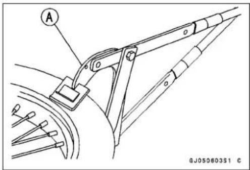
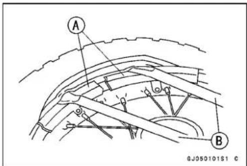
Tires
○Foreasierremoval,alwaysdropthetirebeadopposite thevalvestemintotherimwell[A],andprythetirebead alittleatatime.
- Dothesamefortheothersideofthetire, thenremovethe rimfromthetire.
- Removetheprotectors.
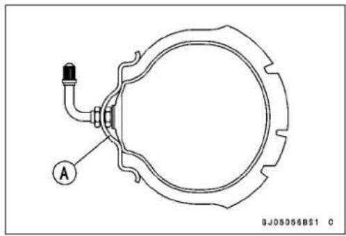
natural_image
Technical line drawing of a mechanical component with labeled point A and reference number 0J05056BS1 (no text or symbols beyond labels)TireInstallation
WARNING
Toensuresafehandlingandstability,useonlythe recommendedstandardtiresforreplacement,inflatedtothestandardpressure.Usethesamemanufacturer'stiresonbothfrontandrearwheels.
NOTE
○Replacetherimbandwithanewonewheneverthetire isreplaced.
- Position the tire on ther im so that the a thetire balance markB.
- Tighten:
Torque - Tire Air Valve Nut: 1.5 N·m (0.15 kgf·m, 13 in·lb) BrakeDiscBolts:27N·m(2.8kgf·m,20ft·lb)
![irvalve[A]isat A B GJ050804S1 C](/content/2026/05/1077878/images/55165e52f376faf74e9b6067b30cf5b58e7e21eb428599707d81a9d3db1ec2ce.jpg)
- Checkthetirerotationmark[A]onthefront/reartireand installitontherimaccordingly.
NOTE
○ Thedirectionofthetirerotation[B]isshownbyanarrow onthetiresidewall.

HubBearings(WheelBearings)
Removal
- Removethewheel, and takeout the following.
SpeedometerGear(fromfronthub)[A]
Collars[B]
GreaseSeals[C]
○Useascrewdriverforthegreasesealremoval.
- Removethehubbearings[A].
CAUTION
Donotlaythewheelonthegroundwiththedisc facingdown. This candamageorwarpthedisc. Placeblocksunderthewheelsothatthediscdoes nottouchtheground.
SpecialTools-BearingRemoverShaft,9:57001-1265[B]
BearingRemoverHead, 15×1757001
-1267[C]
Installation
- Beforeinstallingthewheelbearings, blowanydirtorforeignparticlesoutofthehubwithcompressedairtopreventcontaminationofthebearings.
- Replacethebearingswithnewones.
○Installthebearingsssothatthemarkedsidefacesout.
○Pressineachrightbearing[A]firstuntilitbottomsout.
SpecialTool-BearingDriverSet:57001-1129[B]
WARNING
Besuretobottomouttherightbearingsonboth frontandrearwheels,ormisalignmentofthewheel willresultinabnormaldrivechainwear,andmay resultinanunsaferidingcondition.
- Replacethegreasesealinthefronthubwithanewone.
- Pressinthegreaseseal[A]sothatthesealsurfaceflush [B]withtheendofthehole.
○Applyhightemperaturegreasetothegreaseseallips.
SpecialTool-BearingDriverSet:57001-1129[C]


HubBearings(WheelBearings)
Inspection
○ Sincethehubbearingsaremadetoextremelyclosetolerances, the clearance cannot normally be measured.
NOTE
- Donotremoveanybearingsforinspection.Ifanybearingsareremoved,theywillneedtobereplacedwith newones.
- Spin[A]thebearingbyhandtocheckitscondition.
★ Ifitisnoisy, does not spins smoothly, or has any rough spots, it must bereplaced. - Examinetherearhubbearingseal[B]fortearsorleakage.
★ Ifthesealistornorisleaking, replacethebearing.
Lubrication
CAUTION
Donotremoveanybearingsforlubrication.Ifany bearingsareremoved,theywillneedtobereplaced withnewones.
- Packthefronthubbearingswithgoodqualitybearing grease. Turnthebearingsaroundbyhandafewtimes tomakesurethegreaseisdistributedevenlyinsidethe bearings.
NOTE
○Sincetherearhubbearingarepackedwithgreaseand sealed,lubricationisnotrequired.
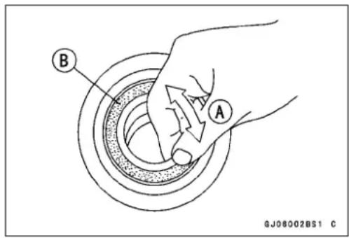
FinalDrive
TableofContents
Exploded View.... 10-2
Specifications 10-4
Special Tools 10-5
Drive Chain.... 10-6
Chain Slack Inspection 10-6
Chain Slack Adjustment.... 10-6
Wear Inspection.... 10-6
Lubrication 10-6
Drive Chain Removal 10-6
Drive Chain Installation 10-6
Sprocket, Coupling 10-7
Engine Sprocket Removal 10-7
Engine Sprocket Installation 10-7
Rear Sprocket Removal 10-8
Rear Sprocket Installation.... 10-8
Sprocket Wear 10-8
Sprocket Warp Inspection.... 10-8
Coupling Removal.... 10-8
Coupling Installation.... 10-9
Coupling Bearing Removal 10-9
Coupling Bearing Installation 10-9
Coupling Bearing Wear/Lubrication 10-9
Damper Inspection.... 10-9

ExplodedView
| No.Fastener | Torque | Remarks | |||
| N·mkgf | ·mft·lb | ||||
| 1 | Engine Sprocket Cover Bolts (BN125-A1 ~ A3) | 9.8 | 1.0 | 87 in·lb | |
| Engine Sprocket Cover Bolts (BN125-A4 ~) | 8.8 | 0.90 | 78 in·lb | ||
| 2 | EngineSprocketCoverDamperBolts | 8.80.90 | 78in·lbL | ||
| 3 | Torque Link Bolt and Nut | 34 | 3.5 | 25 | |
| 4 | Rear Sprocket Nuts | 26 | 2.7 | 19 | |
| 5 | Rear Axle Nuts | 98 | 10.0 | 72 | |
| 6 | Engine Sprocket Bolts | 12 | 1.2 | 102 in·lb | |
- Facethe punchmark outward.
- For DE of BN125-A1 \~ A2 and On and after BN125-A3 of EUR Models
- BN125-A1 \~ A2 Models only
CO:Apply chainoil.
L: Applyanon-permanentlocking agent.
R: Replacement Parts
DE:Germany
EUR: Europe
Specifications
| ItemStandardServiceLimit | ||
| DriveChain | ||
| StandardChain:Make/type: | ENUMA CHAIN (BN125-A1 ~ A2)JointEndlessEK428SH-RDAIDO(BN125-A3~ )JointEndlessDID424HG | --- |
| Link:132links-- -- | 130links(BN125-A7~, N , N U ) -- --25 ~ 40 mm (0.98 ~ 1.57 in.)254.0 ~ 254.6 mm (10.00 ~ 10.02 in.) | ---259mm(10.2in.) |
| Chain Slack20-linkLength | ||
| SprocketsRearSprocketWarpTIR0.4mm(0.016in.)orless | TIR0.5mm(0.020in.) | |
N: No Catalytic Converter Model
NU:NoCatalyticConverter(UnitedKingdomModel)
SpecialTools
BearingDriverSet: 57001-1129

natural_image
Isometric line drawing of a box containing multiple circular components, no text or symbols presentJack: 57001-1238

natural_image
Technical line drawing of a mechanical support structure (no text or symbols)DriveChain
ChainSlackInspection
- RefertotheDriveChainSlackInspectioninthePeriodic Maintenancechapter.
ChainSlackAdjustment
- RefertotheDriveChainSlackAdjustmentinthePeriodic Maintenancechapter.
WearInspection
- RefertotheDriveChainWearInspectioninthePeriodic Maintenancechapter.
Lubrication
- RefertotheDriveChainLubricationinthePeriodicMaintenancechapter.
DriveChainRemoval
- Removetheenginesprocketcover[A].
- Removetheclip[A]fromthemasterlinkusingpliers,and removethechainfromtherearsprocket.
• Takethechainoffthemotorcycle.
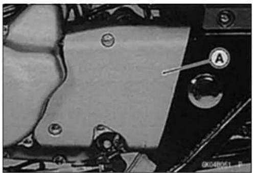
natural_image
Close-up of a mechanical component with labeled parts (A) and mounting holes, no readable text or symbols beyond labels
natural_image
Close-up of a mechanical chain component with labeled point A (no readable text or symbols beyond label)DriveChainInstallation
WARNING
Forsafety, useonlythestandardchain.
- Fitthedrivechainbackontothesprocketswiththeends attherearsprocket.
• Installthemasterlinkfromtheframeside. - Installtheclip[A]sothattheclosedendofthe"U"[B] pointedinthedirectionofchainrotation[C].
- Adjustthedrivechainslack(seePeriodicMaintenance chapter).
- Checkthebrakeforgoodbrakingpower,andnobrake drag(seeBrakeschapter).
WARNING
Ifafullbrakepedalisnotobtained,disassemble andinspectthebrakeparts.Wornpartscauselock ofthebrakeorlossofbraking.

Sprocket, Coupling
EngineSprocketRemoval
- Removetheenginesprocketcoverbolts[A]andsprocket cover[B].
- Removetheenginesprocketbolts[A].
- Pulltheenginesprocket[A]offtheoutputshaftalongwith thechain.
EngineSprocketInstallation
- Installtheenginesprocketsothatthepunchmark[A]face theoutward.
- Tightentheenginesprocketbolts
Torque-EngineSprocketBolts:12N·m(1.2kgf·m,104in·lb)
NOTE
○Whentighteningtheholderbolts, holdtherearbrake on.
- Installtheenginesprocketcover, andtightenthebolts withspecifiedtorque.
Torque-EngineSprocketCoverBolts
(BN125-A1\~A3):9.8N·m(1.0kgf·m,87in·lb)
(BN125-A4\~): 8.8 N·m (0.90 kgf·m, 78 in·lb)
- Runthealternatorleads, crankshaftsensorleads[A], and neutralswitchleads[B]asshown.
Runundertheoilpipe[C].
GuideRib[D]
- Adjustthedrivechain(seePeriodicMaintenancechapter).
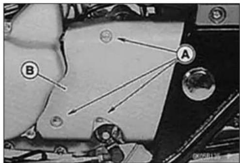

natural_image
Mechanical assembly diagram showing chain links and components (no readable text or symbols)
natural_image
Close-up of hands assembling a mechanical component with chains and gears (no visible text or symbols)

10-8FINALDRIVE
Sprocket, Coupling
RearSprocketRemoval
- Removetherearwheel(seeWheels/Tireschapter).
- Removethedrivechain(seeDriveChainRemoval).
- Removetherearsprocketnuts[A]andseparatetherearsprocket[B]fromthecoupling.
RearSprocketInstallation
- Installthesprocketwiththetoothnumbermarking[A]outward.
- Tightentherearsprocketnuts.
Torque-RearSprocketNuts:26N·m(2.7kgf·m,19ft·lb)
SprocketWear
- Visuallyinspecttheengineandrearsprocketteeth.
★Iftheteetharewornasillustrated, replacethesprockets, and inspect the drivechain (see Periodic Maintenance chapter).
NOTE
○ Sprocketwearisexaggeratedforillustration.
WornTooth(EngineSprocket)[A]
WornTooth(RearSprocket)[B]
DirectionofRotation[C]
CAUTION
Ifasprocketrequiresreplacement,thedrivechain isprobablywornalso.Uponreplacingtherear sprocket,inspectthechainandenginesprocket.
SprocketWarpInspection
- Raisetherearwheeloffthegroundwithajack.
SpecialTool-Jack:57001-1238 - Setadialgauge[A]againsttherearsprocket[B]nearthe teethasshown.
- Turn[C]therearwheel. Thedifferencebetweenthehighestandlowestdialgaugereadingsistheamountofrunout (warp).
★If the runout exceeds the service limit, replace the rear sprocket.
RearSprocketWarp
Standard: TIR0.4mm(0.016in.) or less
ServiceLimit: TIR0.5mm(0.020in.)
CouplingRemoval
- Removetherearwheel(seeWheels/Tireschapter).
- Removetherearsprocket(seethischapter).
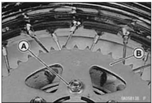


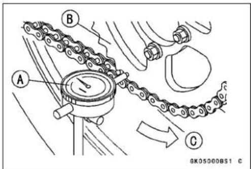
Sprocket, Coupling
Coupling Installation
- Grease[A]thefollowingandinstallthecoupling. CouplingGreaseSealLips. CouplingInternalSurface
- Installtherearsprocketandthecoupling(seethischapter).
• Installtherearwheel(seeWheels/Tireschapter).

CouplingBearingRemoval
- Removethecoupling.
- Prythegreasesealout.
- Removethebearing[A]bytappingfromthewheelside. SpecialTool-BearingDriverSet:57001-1129[B]

CouplingBearingInstallation
- Replacethebearing[A]withanewone.
- Pressinthebearingwiththemarkedsideoutunititbottomsout.
SpecialTool-BearingDriverSet:57001-1129[B]
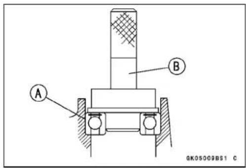
CouplingBearingWear/Lubrication
- SeethelInspectionandLubricationsectionsoftherear hubbearingsinWheels/Tireschapter.
DamperInspection
- Removetherearwheelcoupling, and inspecttherubber dampers[A].
- Replacethedamperifitappearsdamagedordeteriorated.
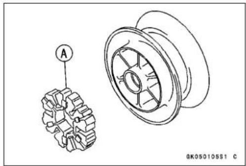
Brakes
TableofContents
ExplodedView....11-2
Specifications....11-6
SpecialTools....11-7
Caliper....11-8
CaliperRemoval....11-8
CaliperInstallation....11-8
CaliperDisassembly......11-8
CaliperAssembly....11-9
CaliperFluidSealDamage......11-10
CaliperDustSeal/FrictionBoot Damage....11-11
CaliperPistonandCylinder Damage....11-11
CaliperHolderShaftWear......11-11
FrontBrakePads....11-12
BrakePadRemoval(BN125-A1\~A2)....11-12
BrakePadRemoval(BN125-A3\~)....11-12
BrakePadInstallation(BN125-A1 \~ A2)....11-12
BrakePadInstallation(BN125-A3 \~)....11-12
BrakePadWearInspection......11-12
MasterCylinder....11-13
MasterCylinderRemoval......11-13
MasterCylinderInstallation.....11-13
MasterCylinderDisassembly.....11-13
MasterCylinderAssembly......11-14
MasterCylinderInspection(Visual Inspection)....11-14
FrontBrakeDisc....11-15
BrakeDiscRemoval....11-15
BrakeDisclInstallation....11-15
BrakeDiscWear....11-15
BrakeDiscWarp....11-15
BrakeFluid....11-16
BrakeFluidLevelInspection......11-16
BrakeFluidChange....11-16
BrakeLineBleeding....11-16
BrakeHose....11-17
BrakeHoseRemoval/Installation.11-17
BrakeHoseInspection......11-17
RearBrakePedalandBrakeCable..11-18
BrakePedalPosition Inspection/Adjustment.....11-18
BrakePedal Free Play Inspection/Adjustment.....11-18
BrakePedalRemoval....11-18
BrakePedallInstallation....11-19
BrakeCableRemoval....11-19
BrakeCableInstallation....11-20
BrakeCableLubrication....11-20
RearBrakePanelandDrum......11-21
BrakePanelRemoval....11-21
BrakePanelInstallation....11-21
BrakePanelDisassembly......11-21
BrakePanelAssembly....11-21
BrakePanelInspection....11-22
Brake Shoe LiningWear Inspection....11-22
BrakeShoeSpringsInspection....11-23
BrakeDrumWearInspection......11-23

ExplodedView
| No.Fastener | Torque | Remarks | |||
| N·mkgf | ·mft·lb | ||||
| 1BrakeDiscBolts272.820L | |||||
| 2CaliperMountingBolts252.518 | |||||
| 3CaliperHolderShaftBolts181.813 | |||||
| 4CaliperPadBolts181.813 | |||||
| 5 | Caliper Bleed Valve | 7.8 | 0.80 | 69 in·lb | |
| 6BrakeHoseBanjoBolts | 252.518 | ||||
| 7 | Brake Lever Pivot Bolt | 5.9 | 0.60 | 52 in·lb | |
| 8 | Brake Lever Pivot Bolt Locknut | 5.9 | 0.60 | 52 in·lb | |
| 9 | FrontMasterCylinderClampBolts | 8.8 | 0.90 | 78in·lb | S |
| 10 | Front Brake Reservoir Cap Screws | 1.5 | 0.15 | 13 in·lb | |
| 11 | Front Brake Light Switch Screws | 1.0 | 0.10 | 9 in·lb | |
- Diaphragm plate (BN125-A1 \~ A2)
- BN125-A1 \~ A2
B: Applybrake fluid.
R: ReplacementParts
S: Follow the specific tightening sequence.
Si: ApplysiliconegreaseorPBCgrease.
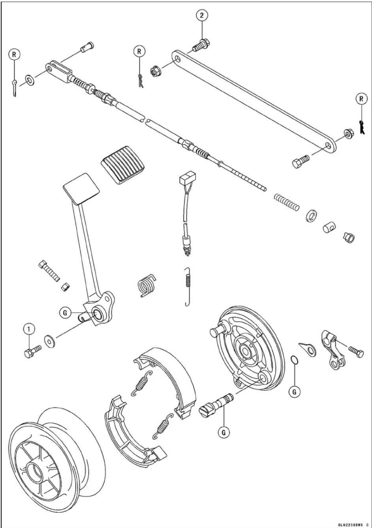
ExplodedView
| No.Fastener | Torque | Remarks | ||
| N·mkgf | ·mft·lb | |||
| 1BrakePedalBolt9.81.087in·lb | ||||
| 2TorqueLinkBoltandNut343.525 | ||||
G:Applygrease.
R: ReplacementParts
Specifications
| ItemStandardServiceLimit | ||
| FrontBrake | ||
| PadLiningThickness: | 4.5 mm (0.177 in.) (BN125-A1 ~ A2) | 1 m (0.04 in.) |
| 6.0 mm (0.236 in.) (BN125-A3 ~ ) | 1 m (0.04 in.) | |
| Disk Thickness | 3.8 ~ 4.2 mm (0.150 ~ 0.165 in.) | 3.5 mm (0.138 in.) |
| 4.3 ~ 4.7 mm (0.169 ~ 0.185 in.) | 4.0 mm (0.157 in.) | |
| (BN125-A3,NO,ES) | ||
| (BN125-A4~ ) | ||
| DiscRunout | Lessthan0.2mm(0.008in.)0.3mm(0.012in.) | |
| BrakeFluid: | ||
| Grade | DOT4 | -- -- |
| RearBrake | ||
| ShoeSpringFreeLength: | ||
| Long | 44.5 ~ 45.5 mm (1.752 ~ 1.791 in.) | 47.2 mm (1.86 in.) |
| Short | 32.5 mm (1.280 in.) | 34.1 mm (1.34 in.) |
| Cam Lever Angle | 80 ~ 90° | -- -- |
| Brake Pedal Free Play | 20 ~ 30 mm (0.79 ~ 1.18 in.) | -- -- |
| BrakeMaintenance | ||
| Brake Drum Inside Diameter | 130.00 ~ 130.16 mm (5.118 ~ 5.124 in.) | 130.75 mm (5.148 in.) |
| Brake Shoe Lining Thickness | 3.85 ~ 4.15 mm (0.152 ~ 0.163 in.) | 2 mm (0.08 in.) |
| Brake Camshaft Diameter | 11.957 ~ 11.984 m (0.471 ~ 0.472 in.) | 11.88 mm (0.47 in.) |
| (BN125-A1~ A6) | ||
| 14.95 ~ 14.99 mm (0.589 ~ 0.590 in.) | 14.88 mm (0.59 in.) | |
| (BN125-A7 ~ and A8 ~, US) | ||
| Brake Camshaft Hole Diameter | 12.000 ~ 12.027 mm (0.472 ~ 0.474 in.) | 12.15 mm (0.478 in.) |
| (BN125-A1~ A6) | ||
| 15.000 ~ 15.027 mm (0.591 ~ 0.592 in.) | 15.15 mm (0.596 in.) | |
| (BN125-A7 ~ and A8 ~, US) | ||
ES:Spain
NO:Norway
US:UnitedStates
SpecialTools
InsideCirclipPliers: 57001-143

natural_image
Line drawing of a pair of pliers (no text or symbols on the image itself)Jack: 57001-1238

natural_image
Technical line drawing of a mechanical support structure (no text or symbols)Caliper
CaliperRemoval
- Loosenthebanjobolt[A]atthebrakehoselowerend, andtightenitloosely.
- Unscrewthecalipermountingbolts[B], and detach the caliper[C] fromthedisc.
- Unscrewthebanjoboltandremovethebrakehose[D] fromthecaliper(seeBrakeHoseRemoval/Installation).
CAUTION
Immediatelywashawayanybrakefluidthatspills.
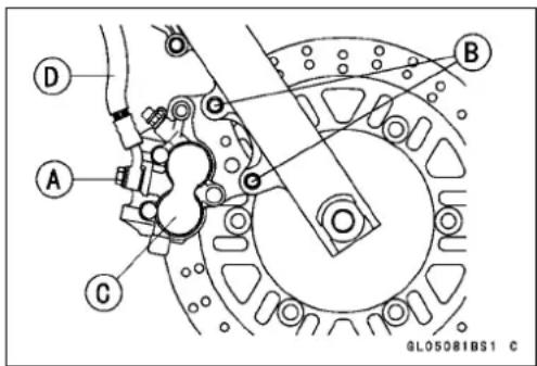
NOTE
○ Ifthecaliperistobedisassembledafterremovalandif compressedairisnotavailable,disassemblethecaliper beforethebrakehoseisremoved(seeCaliperDisassembly).
CaliperInstallation
- Installthecaliperandbrakehoselowerend.
○Replacethewashersthatareoneachsideofhosefitting withnewones. - Tighten:
Torque-CaliperMountingBolts:25N·m(2.5kgf·m,18ft·lb)
BrakeHoseBanjoBolt:25N·m(2.5kgf·m,18ft·lb)
- Checkthefluidlevelinthebrakereservoir.
- Bleedthebrakeline(seeBleedingtheBrakeLine).
- Checkthebrakeforgoodbrakingpower,nobrakedrag, andnofluidleakage.

WARNING
Donotattempttodrivethemotorcycleuntilafull brakeleverisobtainedbypumpingthebrakelever untilthepadsareagainstthedisc. Thebrakewill notfunctiononthefirstapplicationoftheleverif thisisnotdone.
CaliperDisassembly
- Removethecaliper(seeCaliperRemoval).
- Removethepadsandspring(seeBrakePadRemoval).
- Usingcompressedair,removethepistons.
○Lightlyapplycompressedairtothehosejointopening.

WARNING
To avoid serious injury, never place your fingers or palminidethecaliper opening. If you apply compressed air into the caliper, the piston may crush your hand or fingers.
Caliper
○Insertawoodenboard[A]5mm(0.2in.)thickinsidethe caliperopening.
○Applycompressedair[B]tothebanjoboltholetoallow thepistons[C]toprotrudeandstopatthewoodenboard.
○Removethewoodenboardandpulloutthepistonsby hand.
★ Ifcompressedairisnotavailable, withthebrakehose stillattached, applythebrakelevertoremovethepistons. Theremainingprocessisasdescribedabove.
- Remove: DustSeals[A] FluidSeals(pistonseals)[B] CaliperHolder[C] FrictionBoot[D] BleedValve RubberCap
CAUTION
Immediatelywashawaybrakefluidthatspills.

BN125-A1\~A2

BN125-A3\~
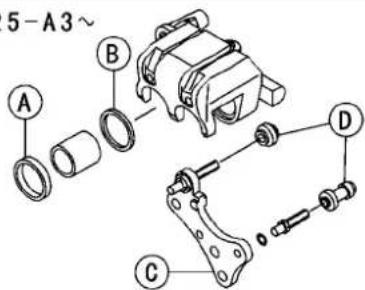
GLO5083BS1 C
CaliperAssembly
- Cleanallpartsotherthantheouterandinnerpads.
CAUTION
Forcleaningtheparts, use only discbrakefluid, isopropylalcohol, orethylalcohol
• Installthebleedvalve[A]andtherubbercap[B].
- Tighten:
Torque-CaliperBleedValve:7.8N·m(0.80kgf·m,69in·lb)
- Replacethefluidseals[A]withnewones,applybrake fluidtothem,andinstalltheminthecaliperbody.Either sideofthefluidsealmayfaceoutboard.
- Checkthedustseals[B]andreplacethemwithnewones iftheyaredamaged.

GL05015BS1 C

GL050402S1 C
11-10BRAKES
Caliper
- Applybrakefluidtotheinsideofthecylindersandtothe outsideofthepistonsandpushthepistons[A]intothe cylinders.
- Checkthefrictionboot[B]anddustboot[C]andreplace themwithnewonesiftheyaredamaged.
- Applyathincoatofsilicongreasetotheholdershafts[D] andtheholderholes.


- Install:
PadSpring[A]
CaliperHolder[B]
PadsandCaliperPadBolts
- Tighten:
Torque-CaliperPadBolts:18N·m(1.8kgf·m,13ft·lb)
- Installthecaliper(seeCaliperInstallation).

CaliperFluidSealDamage
Thefluidseal(pistonseal)[A]isplacedaroundthepistontomaintainclearancebetweenthepadandthedisc. If thesealisinapoorcondition, itcouldleadthepadtowear excessivelyorthebraketodrag, whichmaycausethetemperatureofthediscorthebrakefluidtoincrease.
- Replacethefluidsealifitexhibitsanyoftheconditions listedbelow.
○Brakefluidleakagearoundthepad.
○Brakesoverheat.
○Considerabledifferenceininnerandouterpadwear.
○Sealandpistonarestucktogether.
★Ifthefluidsealisreplaced, replacethedustseal[B]as well. Also, replaceallsealseveryothertimethepadsare changed.


Caliper
CaliperDustSeal/FrictionBootDamage
- Check that the dust seal and friction boot[C] are not cracked, worn, swollen, or other wisedamaged.
- Iftheyshowanydamage,replaceit.
CaliperPistonandCylinderDamage
- Visually inspect the piston[D] and cylinders surfaces for damage.
★Replacethecaliperifthecylinderandpistonarebadly scoredorrusty.
CaliperHolderShaftsE
CaliperHolderShaftWear
Thecaliperbodymustslidesmoothlyonthecaliperholder shafts.Ifthebodydoesnotslidesmoothly,onlyonepad willwearmorethantheother,padwearwillincrease,and constantdragonthediscwillraisethebrakeandbrakefluid temperature.
- Visually inspect the caliper holders' shafts for excessive wear or warp, and rubber friction boots for damage.
★ Iftherubberfrictionbootisdamaged, replacetherubber frictionboot.
★ Ifthecaliperholdershaftisdamage, replacethecaliper holder.
FrontBrakePads
BrakePadRemoval(BN125-A1 \~A2)
- Removethecaliperwiththehoseattached.
- Remove:
CaliperPadBolts[A]
OuterPad[B]
- Removetheinnerpad(pistonsidepad)[C].
BrakePadRemoval(BN125-A3 \~)
- Loosenthecaliperpadbolts[A].
- Removethecaliperwiththehoseattached.
- Remove:
CaliperPadBolts
Pads
BrakePadInstallation(BN125-A1 \~A2)
- Beforeinstallation,cleanthepadswithahigh-flashpoint solvent.
- Pushthecaliperpistoninbyhandasfarastheywillgo.
○Theinnerpadhasawear-protectplate[A].Donotmixup theouterpadandtheinnerpad. - Tighten:
Torque-CaliperPadBolts:18N·m(1.8kgf·m,13ft·lb)
BrakePadInstallation(BN125-A3
- Beforeinstallation,clanthepadswithahigh-flashpoint solvent.
- Pushthecaliperpistonsinbyhand[A]asfarastheywill go.
• Installthepadsandcaliperpadbolts. - Tighten:
Torque-CaliperPadBolts:18N·m(1.8kgf·m,13ft·lb)
- Instalthecaliper(seeCaliperInstallation).

WARNING
Donotattempttodrivethemotorcycleuntilafull brakeleverisobtainedbypumpingthebrakelever untilthepadsareagainstthedisc. Thebrakewill notfunctiononthefirstapplicationoftheleverif thisisnotdone.
BrakePadWearInspection
- RefertotheBrakePadWearInspectioninthePeriodic Maintenancechapter.


natural_image
Close-up of hands assembling mechanical components with visible wiring and a labeled section (no readable text or symbols)
MasterCylinder
MasterCylinderRemoval
- Removethebrakefluidfromthereservoirwithasyringe orothersuitabledevice.
- Disconnectthefrontbrakelightswitchconnectors[A].
- Removethebanjobolt[B]todisconnectthebrakehose fromthemastercylinder(seeBrakeHoseRemoval/Installation).
When removing the brakehose, temporarily secure the endof the brakehosetosamehigh placeto keep fluid lossto a minimum. - Unscrewtheclampbolts[A], and takeoffthemastercylinder[B] as an assembly with the reservoir, brakelever, and brakeswitch installed.
When removing themastercylindertakecarenottospill thebrakefluidonthepaintedorplasticparts.
CAUTION
Immediatelywashawayanybrakefluidthatspills.
MasterCylinderInstallation
- Setthemastercylindertomatchitsmatingfacetothe punchedmark[A]ofthehandlebar.
- Themastercylinderclampmustbeinstalledwiththearrowmark[B]facedupward.
- Tightentheupperclampbolt[C]first,andthenthelower clampbolt[D].Therewillbeagapatthelowerpartofthe clampaftertightening.
Torque-MasterCylinderClampBolts:8.8N·m(0.90kgf·m, 78in·lb)
- Replacethewashersthatareoneachsideofthehose fittingwithnewones.
- Tighten:
Torque-BrakeHoseBanjoBolt:25N·m(2.5kgf·m,18ft·lb)
- Bleedthebrakeline(seeBleedingtheBrakeLine).
- Checkthebrakeforgoodbrakingpower,nobrakedrag, andnofluidleakage.
MasterCylinderDisassembly
- Removethemastercylinder(seeMasterCylinderRemoval).
- Removethereservoircapanddiaphragm, and pour the brakefluid into a container.
- Unscrewthepivotnutandpivotbolt, andremovethe brakelever.
- Pullthedustcoveroutofplace, andremovethecirclip. SpecialTool-InsideCirclipPliers:57001-143
- Pulloutthepistonassembly[A], returnspring[B].
CAUTION
Donotremovethesecondarycup[C]fromthepistonsinceremovalwilldamageit.

natural_image
Mechanical assembly diagram showing components labeled A and B, with no readable text or symbols beyond labels


MasterCylinderAssembly
- Beforeassembly, cleanallpartsincludingthemaster cylinderwithbrakefluidoralcohol.
CAUTION
Exceptforthediscpadsanddisc,useonlydisc brakefluid,isopropylalcohol,orethylalcoholfor cleaningbrakeparts.Donotuseanyotherfluidfor cleaningtheseparts,Gasoline,engineoil,orany otherpetroleumdistillatewillcausedeteriorationof therubberparts.Oilspilledonanypartwillbedifficulttowashoffcompletely,andwilleventuallydeterioratetherubberusedinthediscbrake.
- Applybrakefluidtotheremovedpartsandtotheinner wallofthecylinder.
- Takecarenottoscratchthepistonortheinnerwallofthe cylinder.
- Applysiliconegrease(ex.PBCgrease)tothefollowing points.
BrakeLeverPivotBolt BrakeLeverPivotContact DustCover
- Tighten:
Torque-BrakeReservoirCapScrews:1.5N·m(0.15kgf·m, 13in·lb)
BrakeLeverPivotBolt:5.9N·m(0.60kgf·m,52in·lb)
BrakeLeverPivotLocknut:5.9N·m(0.60kgf·m, 52in·lb)
MasterCylinderInspection(VisualInspection)
- Disassemblethemastercylinder.
- Check that there are nos scratches, rust or pitting on the inner wall [A] of them a Master cylinder and on the outside of the piston [B].
★Ifamastercylinderorpistonshowsanydamage,replace them. - Inspecttheprimarycup[C]andsecondarycup[D].
★Ifacupisworn,damagedsoftened(rotted),orswollen, thepistonassemblyshouldbereplacedtorenewthe cups.
★Iffluidleakageisnotedatthebrakelever,thepistonassemblyshouldbereplacedtorenewthecups. - CheckthedustcoverEfordamage.
★Ifthedustcoverisdamaged,replaceit. - Checktherelief[F]andsupply[G]portsarenotplugged.
★Ifthereliefportbecomesplugged,thebrakepadswill dragonthedisc.Blowtheportscleanwithcompressed air. - Checkthepistonreturnsprings[H]foranydamage.
★Ifthespringisdamaged,replaceit.
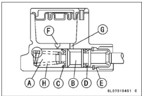
FrontBrakeDisc
BrakeDiscRemoval
- Removethewheel(seeWheels/Tireschapter).
- Unscrewthemountingbolts, and takeoffthedisc.
BrakeDiscInstallation
- Installthebrakedisconthewheelsothatthemarkedside [A]facesout.
- Tighten:
Torque-BrakeDiscMountingBolts[B]:27N·m(2.8kgf·m, 20ft·lb)

BrakeDiscWear
- Visuallyinspectthedisk.
★Replacethediscifitshowsanydamageorcrack. - Measurethethicknessofthedisc[A]atthepointwhereit haswornthemost.
★ Ifthedischaswornpasttheservicelimit,replaceit. [B]MeasuringArea
BrakeDiscThickness
Standard: 3.8 \~ 4.2 mm (0.150 \~ 0.165 in.) 4.3 \~ 4.7 mm (0.169 \~ 0.185 in.) (BN125-A3, Norway and Spain) (BN125-A4\~ )
ServiceLimit:3.5mm(0.138in.) 4.0mm(0.157in.) (BN125-A3,NorwayandSpain) (BN125-A4\~ )

natural_image
Technical drawing of a mechanical bearing assembly with circular components and mounting holes (no text or symbols)BrakeDiscWarp
- Usingajack, raisethewheelofftheground(see Wheels/Tireschapter).
SpecialTool-Jack:57001-1238
○Forfrontdiscinspection,turnthehandlebarfullytoone side. - Setupadialgaugeagainstthedisc[B]asshownand measureddiscrunout,whileturning[A]thewheelbyhand.
★ Ifrunoutexceedstheservicelimit, replacethedisc.

DiscRunout
Standard: Less than 0.12mm (0.008in.) or less ServiceLimit: 0.3mm (0.012in.)
BrakeFluid
BrakeFluidLevelInspection
- RefertotheBrakeFluidLevelInspectioninPeriodicMaintenancechapter.
BrakeFluidChange
- RefertotheBrakeFluidChangeinPeriodicMaintenance chapter.
Brake Line Bleeding
- RefertotheBrakeLineBleedinginPeriodicMaintenance chapter.
BrakeHose
BrakeHoseRemoval/Installation
CAUTION
Brakefluidquicklyruinspaintedorplasticsurfaces;anyspilledfluidshouldbecompletelywiped upimmediatelywithwetcloth.
- Whenremovingthebrakehose,takecarenottospillthe brakefluidonthepaintedorplasticparts.
- When removing the brakehose[A], temporarily secure the end of the brakehosetosome high placeto keep fluid loss to a minimum.
- Therearewashers[B]oneachsideofthebrakehose fitting. Replacethemwithnewoneswheninstalling.
- Wheninstallingthehoses, avoidsharpbending, kinking, flatteningortwisting, and routethehos according to Cable, WireandHoseRoutingsection in Appendix chapter.
- Tighten:
Torque-BrakeHoseBanjoBolts[C]:25N·m(2.5kgf·m,18 ft·lb)
- Bleedthebrakelineafterinstallingthebrakehose(see BrakeLineBleeding).
BrakeHoseInspection
- RefertotheBrakeHoseCheckinthePeriodicMaintenancechapter.

11-18BRAKES
RearBrakePedalandBrakeCable
BrakePedalPositionInspection/Adjustment
- Check that the brake pedal [A] is in the correct position.
PedalPosition[C]
Standard: About80mm(3.15in.) abovefootpegtop [B]
★Ifitisincorrect,adjustthebrakepedalposition.
- Loosenthelocknut[A], and turnthead adjusting bolt[B] until the brake pedal is correctly positioned.
- Tightenthelocknut.
- Check:
RearBrakeLightSwitchTiming(seeElectricalSystem chapter)
BrakePedalFreePlay(seeBrakePedalFreePlayInspection)
NOTE
○ Ifthepedalpositioncannotbeadjustedbyturningthe adjustingbolt,thebrakepedalmaybeformedorin-correctlyinstalled.
BrakePedalFreePlayInspection/Adjustment
- RefertotheBrakePedalFreePlayCheckinthePeriodic Maintenancechapter.
BrakePedalRemoval
- Removtheadjustingnutfromtheendofthebrakerod, andtakeoffthejointandbrakerodfromthebrakecam lever.
- Remove:
Bands[A]
Cover[B]
FrontFootpegMountingBolts[C]
- Remove:
CotterPinandJointPin[A]
BrakeCableNut[B]
BrakePedalBolts[C]
RearBrakeLightSwitchSpring[D]


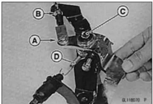
RearBrakePedalandBrakeCable
- Removethebrakepedal[A]andreturnspring[B].
BrakePedallInstallation
- Applygreasetothebrakepedalpivot.
- Temporarily install the braker returns spring onto the brake shaft and hook the spring onto the brake pedal.
- Push[B]thebrakepedal[A]acrossthebrakeshaftand insertthepedalontotheshaft.
• Lightlytightenthebrakepedalbolt[A].
- Prythebrakereturnspring[B]ontothebrakeshaftwitha screwdriver.
- Tightenthebrakepedalbolt.
Torque-BrakePedalBolt:9.8N·m(1.0kgf·m,87ft·lb)
- Hooktherearbrakelightswitchspringandbrakereturn springlowerend.
-
Insertanewcotterpinthroughthejointpin, andspread itsends.
-
Check:
BrakePedalPosition(seeBrakePedalPositionInspection/Adjustment)
BrakePedalFreePlay(seePeriodicMaintenancechapter)
RearBrakeLightSwitchTiming(seePeriodicMaintenancechapter)
• Installthepartsremoved.
BrakeCableRemoval
- Remove:
Bands[A]
Cover[B]
FrontFootpegMountingBolts[C]


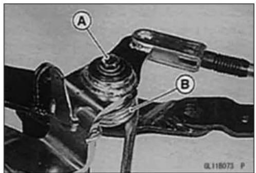

11-20BRAKES
RearBrakePedalandBrakeCable
- Remove: CotterPinandJointPin BrakeCableNut[A]
- Removethesilencer(seeEngineTopEndchapter).
- Removetheadjustingnutontheendofthebrakerod, andtakeoffthejointpinandbrakerodfromthebrake camlever.
- Removethecabledustboot[A].
- Pulltheoutercablehousing[B]forward,andtakeoutthe innercable[C]fromthegrooveofthestay.
- Pullthebrakecableoutoftheframe.


BrakeCableInstallation
- Lubricatethecablebeforeinstallation.
- Adjustthebrakepedalpositionandfreeplay.
BrakeCableLubrication
- Wheneverthecableisremoved,orinaccordancewiththe PeriodicMaintenanceChart,lubricatethebrakecable. RefertoGeneralLubricationinthePeriodicMaintenance chapter.
○Applyathincoatingofgreasetothecableupperend.
○Useacommerciallyavailablepressurecablelubricatorto lubricatethecable.
With the cable disconnected at both ends, the cable should move freely in the cable housing.
RearBrakePanelandDrum
BrakePanelRemoval
- Removetherearwheel(seeWheels/Tireschapter).
- Separatethebrakepanelfromthewheelhub.
BrakePanelInstallation
- Fitthebrakepanelintotherearwheel, and then install therearwheel (see Wheels/Tireschapter).
BrakePanelDisassembly
- Removethebrakepanel(seeBrakePanelRemoval).
- Before removing the brake cam lever, mark[A] the position of the cam lever so that it can be installed later in the same position.
-
Beforeeremovingthebrakeliningwearindicator, markthe positionofthebrakecamshaftandliningwearindicator sothatitcanbeinstalledlaterinthesameposition.
-
Usingacleancloth[B]aroundtheliningstopprevent greaseoroilfromgettingonthem,removethebrake shoes[A]bypullingup[C]onthecenterofthelinings.
- Removethesprings[D]toseparatethetwoshoes.

natural_image
Close-up of mechanical components with no visible text or symbols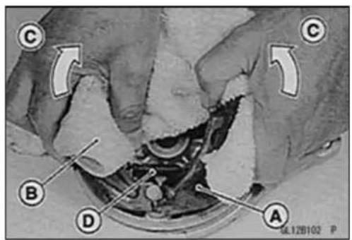
BrakePanelAssembly
- Cleantheoldgreasefromthecamshaftandbrakeshoe anchorpin,andregreasethem.
○Applygreasetothecenterofshaftandverylightlyonthe camsurfaces.Donotovergrease. - Pushthecamshaftintothepanelsothatthetriangular mark[A]onthecamsurfacepointstowardthecenterof thepanel.
WARNING
ImproperInstallationwillcauseineffectivebraking.
- Visuallyinspectthebrakeshoespringsforbreaksordistortion.
★ Ifthespringsaredamagedinanyway, replacethem. - Fitthelargespring[A]andsmallspring[B]ontothebrake shoesasshown.
- Wrapacleanclotharoundtheliningstoppreventgrease oroilfromgettingonthem, and install theshoesonthe brakepanel.

natural_image
Mechanical component diagram showing internal parts and a labeled section (A), no readable text or symbols present.
RearBrakePanelandDrum
- Installthebrakecamsealandfittheindicator[A]onthe serrationsothatitpointstotheextremerightoftheUS-ABLERANGE[B].
- Installthecamleverinitsoriginalpositiononthe camshaft,andtightenitsbolt.
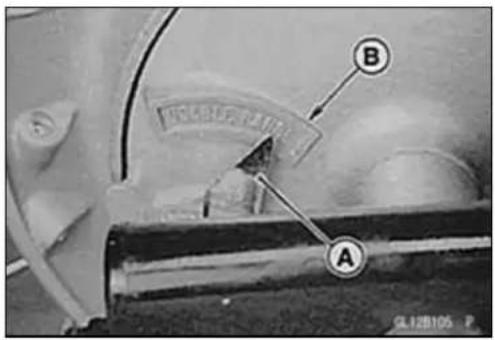
BrakePanellInspection
- Removethebrakepanel(seeBrakePanelRemoval).
- Checkthebrakecamshaftdiameterandthebrake camshaftholediameterofbrakepanels.
BrakeCamshaftDiameter
Standard:
BN125-A1 \~ A6 11.957 \~ 11.984 mm
(0.471\~0.472in.)
BN125-A7 \~ and A8 \~, United 14.95\~ 14.99mm
StatesModels (0.589\~0.590in.)
ServiceLimit:
BN125-A1\~A6 11.88mm(0.47in.)
BN125-A7 \~ and A8 \~, United 14.88mm(0.59in.)
StatesModels
BrakeCamshaftHoleInsideDiameter
Standard:
BN125-A1\~A6 12.000\~12.027mm(0.472\~0.474in.)
BN125-A7 \~ and A8 \~, 15.000\~ 15.027mm(0.591
UnitedStatesModels \~ 0.592in.)
ServiceLimit:
BN125-A1\~A6 12.15mm(0.478in.)
BN125-A7 \~ and A8 \~, 15.15mm(0.596in.)
UnitedStatesModels
★Iftheyareexceedtheservicelimit,replacetheaffected partsofthem.
BrakeShoeLiningWearInspection
- RefertotheBrakeShoeLiningWearInspectioninthe PeriodicMaintenancechapter.
RearBrakePanelandDrum
BrakeShoeSpringsInspection
- Visuallyinspectthebrakeshoespringsforbreaksordistortion.
★ Ifthespringsaredamagedinanyway, replacethem. - Measurethefreelengthofthebrakeshoesprings.
★ Ifeitherisstretchedbeyondtheservicelimit,replaceboth springs.
BrakeShoeSpringsFreeLength
Standard:
Long 44.5 \~ 45.5 mm (1.752 \~ 1.791 in.)
Short32.5mm(1.280in.)
ServiceLimit:
Long 47.2mm(1.86in.)
Short34.1mm(1.34in.)

BrakeDrumWearInspection
- Removetherearwheel(seeWheels/Tireschapter).
- Removethebrakepanel.
- Measuretheinsidediameter[A]ofthedrum.
○ Usecalipersandmeasureatseveralpoints.
★ Ifanymeasurementisgreaterthantheservicelimit,re-placethewheelhub.
★ Ifthedrumiswornunevenlyorscored, lightlyturnthe drumonabrakedrumlatheorreplacethewheelhub.Do notturnthedrumbeyondtheservicelimit.
DrumInsideDiameter
Standard: 130.00 \~ 130.16 mm (5.118 \~ 5.124 in.)
ServiceLimit:130.75mm(5.148in.)
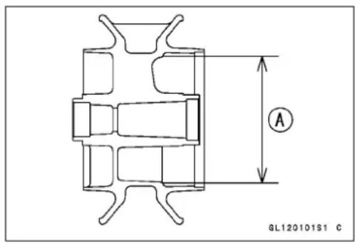
Suspension
TableofContents
Exploded View.... 12-2
Specifications 12-6
Special Tools 12-7
Front Fork 12-8
Fork Oil Change 12-8
Fork Removal 12-8
Fork Installation.... 12-8
Fork Disassembly 12-9
Fork Assembly 12-10
Inner Tube, Outer Tube Inspection 12-11
Spring Inspection 12-12
Rear Shock Absorbers 12-13
Spring Preload Adjustment 12-13
Removal.... 12-13
Installation.... 12-13
Swingarm.... 12-14
Swingarm Removal 12-14
Swingarm Installation.... 12-14
Swingarm Bearing Removal 12-14
Swingarm Bearing Installation 12-14
Swingarm Pivot Check 12-15
SwingarmBearing, SleeveInspection....12-15
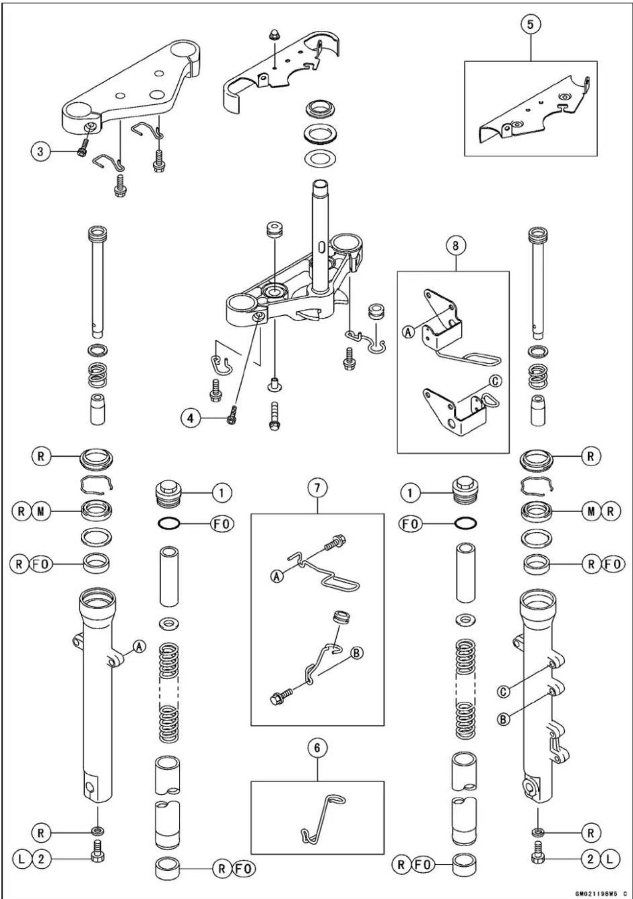
ExplodedView
| No.Fastener | Torque | Remarks | |||
| N·mkgf | mft·lb | ||||
| 1FrontForkTopPlugs232.317 | |||||
| 2FrontForkBottomAllenBolts202.015 | |||||
| 3 | FrontForkClampBolt(Upper) | 202.015 | |||
| 4FrontForkClampBolt(Lower)343.525 | |||||
5.Forkcover(BN125-A1\~A5)
6. Brakehoseclamp(BN125-A1only)
7. Other than the US and CAM models
8. Speedmetercableguide and Brakehoseguide (USandCAModels)
FO:Applyforkoil.
L: Applyanon-permanentlockingagent.
M:Applymolybdenumdisulfidegrease.
R: ReplacementParts
CA:Canada
US:UnitedStates
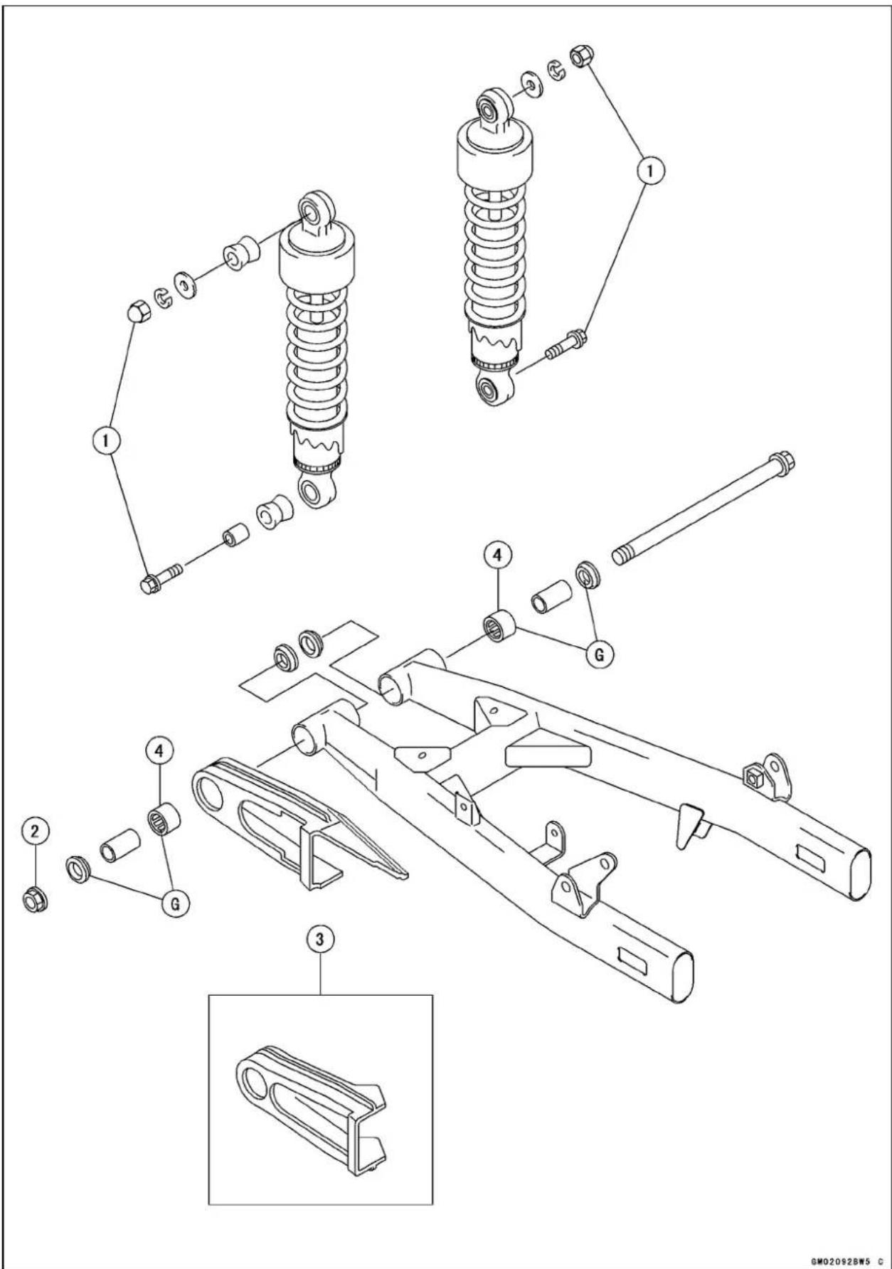
ExplodedView
| No.Fastener | Torque | Remarks | |||
| N·mkgf | mft·lb | ||||
| 1 | Rear Shock Absorber Nuts and Bolts | 34 | 3.5 | 25 | |
| 2SwingarmPivotNut9810.072 | |||||
- Chainguard(BN125-A1 \~ A2only)
- Facethemanufacture's marksout.
Specifications
| ItemStandard | |
| FrontFork(PerOneUnit) | |
| ForkInnerTubeDiameter33mm(1.30in.) | |
| ForkSpringSettingNon-adjustable | |
| AirPressureAtmosphericpressure(non-adjustable) | |
| DamperSettingNonadjustable | |
| ForkOilViscositySHOWASS-8orequivalent | |
| ForkOilCapacity191±2.5mL(6.46±0.085USoz.)(completelydry) | |
| ForkOilLevel218±2mm(8.58±0.08in.)belowfrominnertubetopwithfully | |
| ForkSpringFreeLength398.5mm(15.7in.)(Servicelimit:391mm(15.4in.)) | |
| RearShockAbsorbers | |
| Spring Preload | 1st step (Adjustable range : 1st ~ 5th steps) |
| GasPressureNogas |
SpecialTools
ForkCylinderHolderHandle: 57001-183

natural_image
Simple line drawing of a T-shaped tool or rod with a base, no text or symbols present.ForkCylinderHolderAdapter: 57001-1011

natural_image
Technical line drawing of a conical mechanical component (no text or symbols)OilSeal&BearingRemover: 57001-1058
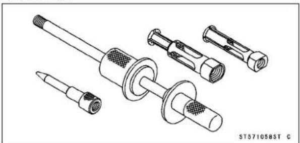
natural_image
Technical line drawing of mechanical components including a shaft, flange, and housing (no text or symbols)BearingDriverSet: 57001-1129

natural_image
Isometric line drawing of a box containing multiple circular components, no text or symbols presentForkOuterTubeWeight: 57001-1218

natural_image
Technical line drawing of a mechanical component with no visible text or symbolsFrontForkOilSealDriver: 57001-1219

natural_image
Technical line drawing of a cylindrical mechanical component with internal cavities (no text or symbols)Jack:
57001-1238
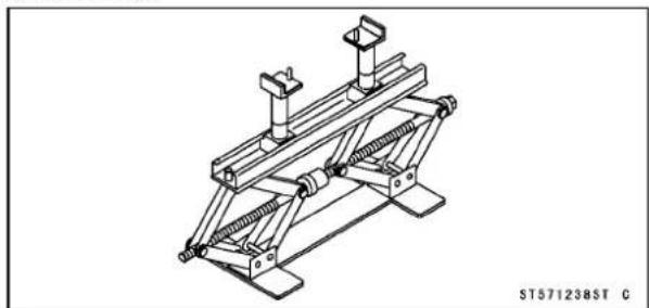
natural_image
Technical line drawing of a mechanical support structure (no text or symbols)HookWrench(Owner'sTool): 92110-1143

natural_image
Line drawing of a wrench tool (no text or symbols on the object itself)FrontFork
ForkOilChange
- RefertotheFrontForkOilChangeinthePeriodicMaintenancechapter.
ForkRemoval
★ Iftheforklegistobedisassembled, loosenthetopplug beforehand. Toloosentheforktopplug, loosenthefork upperclampbolts.
- Remove: BrakeCaliper(seeBrakeschapter) FrontWheel(seeWheels/Tirechapter)
★ Iftheforklegistobedisassembled, loosentheforkbottomAllenbolt[A]beforehand.
- Loosentheupper[A]andlowerforkclampbolts[B].
- Loosentheturnsignallightholderboltandnut[C].
- Withatwistingmotion,worktheforkleg[A]downandout.
ForkInstallation
- Installtheforksothatthetopend[A]oftheinnertubeis flushwiththeuppersurfaceofthesteeringstemhead[B].
- Runthecables, wires, and hosesasshownintheCable, Wire, and HoseRoutingsectionoftheAppendixchapter.
- Tighten:
Torque-FrontForkClampBolts(Upper):20N·m(2.0 kgf·m,15ft·lb)
FrontForkClampBolts(Lower):34N·m(3.4 kgf·m,25ft·lb)
ForkTopPlugs:23N·m(2.3kgf·m,17ft·lb)
TurnSignalLightHolderNut:5.9N·m(0.60kgf·m, 52in·lb)
• Installthefrontwheel(seeWheels/Tireschapter).
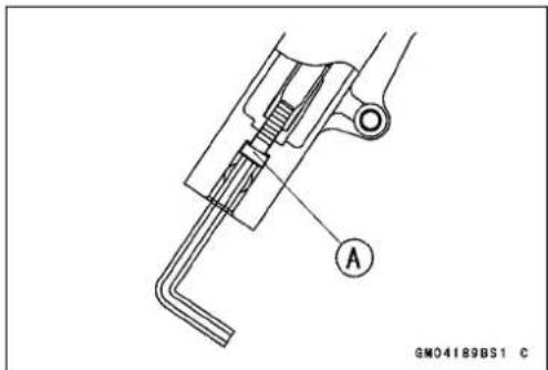

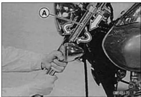

FrontFork
- Checkthefrontbrakeeffectivenessafterinstallation.
A WARNING
Donotattempttoridethemotorcycleuntilafull brakeleverisobtainedbypumpingthebrakelever untilthepadsareagainstthedisc.Thebrakewill notfunctiontothefirstapplicationoftheleverif thisisnotdone.
ForkDisassembly
- Removethefrontfork(seeFrontForkRemoval).
- Draintheforkoil(seePeriodicMaintenancechapter).
○ The following parts are removed during draining the fork oil.
TopRug
Spacer
ForkSpringSeat
ForkSpring
- Holdthefrontforkhorizontallyinavise[A].
- Stopthecylinderunit[B]fromturningbyusingthespecial toolsandAllenwrench.
- UnscrewtheAllenbolt[C], andtakethegasketoutofthe bottomoftheoutertube.
SpecialTools-ForkCylinderHolderHandle:57001-183[D] ForkCylinderHolderAdapter:57001-1011 E
• Takethecylinderunitoutoftheinnertube.
- Removethedustseal[A]fromtheoutertubewithascrewdriver.
- Removetheretainingring[A]fromtheoutertubewitha screwdriver.
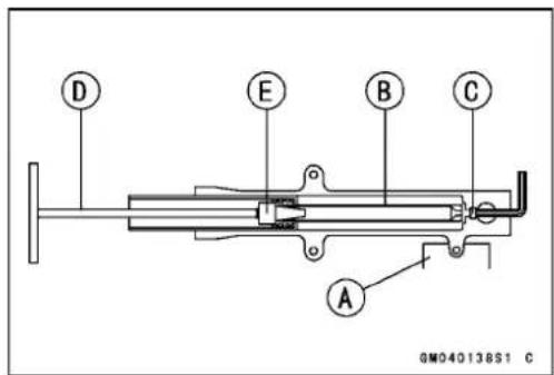
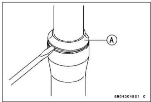

12-10 SUSPENSION
FrontFork
- Usetheforkoutertubeweight[A]toseparatetheouter tube[B]fromtheinnertube[C].Holdingtheinnertube byhand,pulltheoutertubeseveraltimestopulloutthe innertube.
SpecialTool-ForkOuterTubeWeight:57001-1218
• Takeoutthecylinderbaseoutoftheoutertube.
- Removetheguidebushings[A], washer[B], and oilseal [C] from the innertube.
ForkAssembly
- ChecktheO-ringonthetopplugandreplaceitwithanew one.
- Replacethefollowingpartswithnewonesafterremoval. DustSeal[A]
RetainingRing[B]
OilSeal[C]
InnerGuideBushing[D]
OuterGuideBushingE
BottomAllenBoltGasket[F]
- Putthecylinderunit[A]withthespringintotheinnertube[B]protrudingfromtheinnertube,andinstallthecylinderbase[C]ontothebottomendofthecylinderunit.
○Installthecylinderbasewiththetaperedend[D]up.
- Installtheinnertube,cylinderunit,andcylinderbaseas asetintotheoutertube.
- Installthenewguidebushing[A]withausedguidebushing[B]onitbytappingtheusedguidebushingwiththe forkoilsealdriver[C]untilitstops.
○Thesplit[D]ofthebushingsshouldfacetowardthesideof thevehicle.
SpecialTool-FrontForkOilSealDriver:57001-1219
○Removetheusedguidebushing.


FrontFork
- Applymolybdenumdisulfidegreasetotheoilseallipsand installthewasherandoilseal[A]intotheoutertube.
SpecialTool-FrontForkOilSealDriver:57001-1219[B]
- Installtheretainingringanddustsealbyhand.
- Putthenewgasketonthebottomoftheoutertube.
- Applyanon-permanentlockingagenttothethreadsof theAllenboltandscrewtheAllenboltintothebottomof theoutertube.
- Holdtheoutertubehorizontallyinavise[A].
- Holdthecylinderunit[B]withthespecialtoolsandAllen wrench,tightentheAllenbolt[C].
Torque-BottomAllenBolt:20N·m(2.0kgf·m,15ft·lb)
SpecialTools-ForkCylinderHolderHandle:57001-183[D]
ForkCylinderHolderAdapter:57001-1011
- Pourinthespecifiedtypeofoilandinstallthepartsremoved.
ForkOilViscosity:
SHOWASS-8orequivalent
ForkOilCapacity(completelydry):
191±2.5mL(6.46±0.085USoz.)
InnerTube, OuterTubeInspection
- Visuallyinspecttheinnertube[A]andrepairanydamage.
- Nickorrustdamagecansometimesberepairedbyusing awet-stonetoremovesharpedgesorraisedareaswhich causesealdamage.
★ Ifthedamageisnotrepairable,replacetheinnertube. Sincedamagetotheinnertubedamagestheoilseal, replacetheoilsealwhenevertheinnertubeisrepaired orreplaced.
CAUTION
Iftheinnertubeisbadlybentorcreased,replace it.Excessivebending,followedbysubsequent straightening,canweakentheinnertube.
- Temporarily assemble the inner and outertubes[B], and pump them back and forth manually to check for smooth operation.
★ If you feel binding or catching, the inner and outer tubes must bereplaced.
WARNING
Astraightenedinnerorouterforktubemayfailin use, possibly causing an accident. Replace abadly bentordamagedinneroroutertube, and inspect theothertubecarefully before reusing it.


FrontFork
SpringInspection
- Sincetheforkspring[A]becomesshorterasitweakens, checkitsfreelength[B]todetermineitscondition.
★Ifthespringofeitherforklegisshorterthantheservice limit, it must bereplaced. Ifthelengthofthereplacement spring and that oftheremainingspring vary greatly, the remainingsprings should also bereplaced in order to keep the fork legs balanced form motorcycle stability.
ForkSpringFreeLength
Standard:398.5mm(15.7in.)
ServiceLimit:391mm(15.4in.)

RearShockAbsorbers
SpringPreloadAdjustment
- Toadjustthespringforce, turntheadjusteroneachshock absorbertothedesiredposition.
Owner's Tool-HookWrench:92110-1143[A]
SpringPreloadAdjustment
| AdjusterPosition1234 | 5 | ||||
| SpringTension→ Stronger | |||||
WARNING
Ifapairofadjustersarenotadjustedequally, handlingmaybeimpairedandahazardouscondition mayresult.
Removal
- Raisetherearwheelofftheground.
SpecialTool- Jack:57001-1238
- Unscrew the upper mounting nut and lower mounting bolts[A], and removetherearshockabsorber[B].
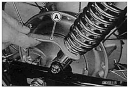
natural_image
Close-up of a car engine component with a spring and labeled section A (no readable text or symbols)
Installation
• Installtherearshockabsorbers.
- Tightentherearshockabsorbernutsandbolts.
Torque-RearShockAbsorberMountingNutandBolt:34 N·m(3.5kgf·m,25ft·lb)
Swingarm
SwingarmRemoval
- Remove:
ChainCover
RearWheel(seeWheels/Tireschapter)
RearShockAbsorberLowerMountingBoltsA
SilencerB
BrakeCableC
PivotNut[D]
FrontE
- Pullouttheswingarmpivotshaft, andremovethe swingarm[A].
- Separatethedrivechain.
SwingarmInstallation
- Applyplentyofgreasetotheinsideoftheneedlebearings andgreaseseals.
- Loopthedrivechain[A]ontotheswingarm.
• Installtheswingarm. - Installtheremovedparts(seeappropriatechapters).
- Tightenthefollowing:
Torque-SwingarmPivotNut:98N·m(10.0kgf·m,72ft·lb)
RearShockAbsorberBolts:34N·m(3.5kgf·m,25ft·lb)
SwingarmBearingRemoval
- Remove:
Swingarm(seethischapter)
Sleeve
GreaseSeals
- Removetheneedlebearings[A], using the oil seal & bearingremover[B].
SpecialTool-OilSeal&BearingRemover:57001-1058
SwingarmBearingInstallation
- Applyplentyofgreasetothenewneedlebearings, sleeve,andgreaseseallip.
- Positionthebushings[A]asshown, usingasuitablebearingdriverinthebearingdriverset.
Besuretoinstalltheneedlebearingsothatthemanufacturer'smarksarefacedout. Thispreventsbearingdamage.
SpecialTool-BearingDriverSet:57001-1129

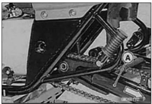
natural_image
Mechanical assembly diagram showing springs and brackets with no visible text or symbols
natural_image
Close-up of a mechanical assembly with springs and components, no visible text or symbols

Swingarm
SwingarmPivotCheck
- Remove:
RearWheel(seeWheels/Tireschapter)
RearShockAbsorberBolts
- Movetheswingarmupanddowntocheckforabnormal friction, and pushandpullittocheckforbushingsplay [A]. Asmallamountofplayonthepivotisnormalandno correctiveactionisneeded. However, if excessive play is felt, checktheswingarmbushingsforwearandreplace themifnecessary.
SwingarmBearing, SleeveInspection
CAUTION
Donotremovethebearingforinspection.Removal maydamagethem.
- Visuallyinspecttheswingarmneedlebearing[A].
○ Therollersinaneedlebearingnormallywearverylittle, andwearisdifficulttomeasure. Insteadofmeasuring, inspectthebearingintheswingarmforabrasion, color change, orotherdamage.
★ Ifthereisanydoubtastotheconditionofanyoftheneedlebearingsorsleeves[B],replaceallthesleeves,and needlebearingsasaset.


Steering
TableofContents
Exploded View 13-2
Special Tools 13-4
Steering 13-5
Steering Inspection 13-5
Steering Adjustment.... 13-5
Steering Stem.... 13-6
Steering Stem Removal 13-6
Steering Stem Installation 13-7
Steering Stem Warp 13-8
Steering Stem Bearing 13-9
Steering Stem Bearing Removal.... 13-9
Steering Stem Bearing Installation.... 13-9
SteeringStemBearingWear, Damage....13-9
Steering Stem Bearing Lubrication 13-9
Handlebar 13-10
HandlebarRemoval(BN125-A1/A2)....13-10
Handlebar Removal (BN125-A3 \~) 13-10
HandlebarInstallation(BN125-A1/A2)....13-10
Handlebar Installation (BN125-A3 \~ ) 13-11
RearViewMirrorRemoval(Europe)....13-11
Rear View Mirrors Installation (Europe).... 13-11
BN125-A1\~

ExplodedView
| No.Fastener | Torque | Remarks | |||
| N·mkgf·mft·lb | |||||
| 1SteeringStemHeadBolts444.533 | |||||
| 2SteeringStemNutHand-tight | or4.9 | Hand-tight or0.50 | Hand-tight or43in·lb | ||
| 3HandlebarNuts343.525 | |||||
| 4 | Handlebar Weight Screws | - | - | - | L |
| 5 | HandlebarSwitchHousingScrews | 3.4 | 0.35 | 30in·lb | |
| 6 | Front Fork Clamp Bolts (Lower) | 34 | 3.5 | 25 | S |
| 7 | Front Fork Clamp Bolts (Upper) | 20 | 2.0 | 15 | S |
| 8 | Handlebar holder clamp bolts | 20 | 2.0 | 15 | S |
- BN125-A3\~
AD: Applyadhesive.
G: Applygrease.
L: Applyanon-permanentlockingagent.
S: Followthespecifictighteningsequence.
SpecialTools
SteeringStemBearingDriver: 57001-137

natural_image
Technical line drawing of a cylindrical mechanical component with a flanged end and internal features (no text or symbols)SteeringStemBearingDriverAdapter,34.5:57001-1074

natural_image
Simple line drawing of a cylindrical mechanical component (no text or symbols)HeadPipeOuterRacePressShaft: 57001-1075

natural_image
Technical line drawing of a mechanical component with threaded ends and a cylindrical shaft (no text or symbols)HeadPipeOuterRaceDriver,51.6:57001-1076

natural_image
Technical line drawing of a mechanical component with a flanged top and central hole (no text or symbols)HeadPipeOuterRaceDriver,46.5:57001-1106
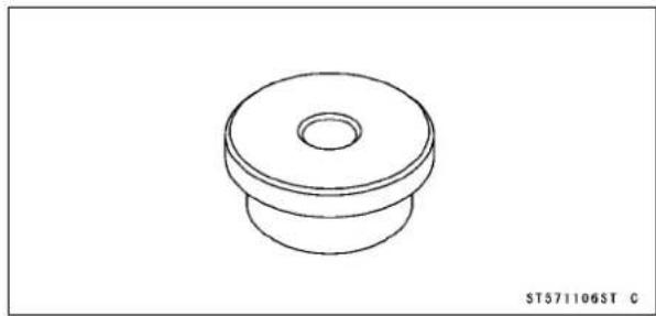
natural_image
Technical line drawing of a mechanical component with a flanged top and circular base (no text or symbols)SteeringStemNutWrench: 57001-1100

natural_image
Line drawing of a mechanical wrench with a curved handle and two notches (no text or symbols)Jack: 57001-1238

natural_image
Technical line drawing of a mechanical support structure (no text or symbols)Steering
SteeringInspection
- RefertotheSteeringInspectioninthePeriodicMaintenancechapter.
SteeringAdjustment
- RefertotheSteeringAdjustmentinthePeriodicMaintenancechapter.
13-6STEERING
SteeringStem
SteeringStemRemoval
- Loosenthesteeringstemheadbolt[A].
- Opentheheadlightbodyandpullofftheconnectorsintheheadlightbody(seeElectricalSystemchapter).
- Removetheclutchcableupperendandleadconnector.
- Loosentheturnsignallightholderboltsandnuts[B].
- Removethenuts[A]andtakeofftheheadlightbody[B].
- Remove:
SteeringStemHeadBolt[A] SteeringStemHead[B] FrontForkC ○Removethesteeringstemheadwiththemeterunitand handlebarleftinstalled.
- Pushuponthestembase[A], andremovethestemnut [C] with thesteeringstemnutwrench[B], then remove thesteeringstem.
SpecialTool-SteeringStemNutWrench:57001-1100
- Remove:
LowerInnerRaceandSteelBalls(20)
SteeringStemCap[A]
UpperInnerRaceandSteelBalls(19)

natural_image
Close-up of a motorcycle's head and side components, labeled A and B, with no visible text or symbols beyond labels.

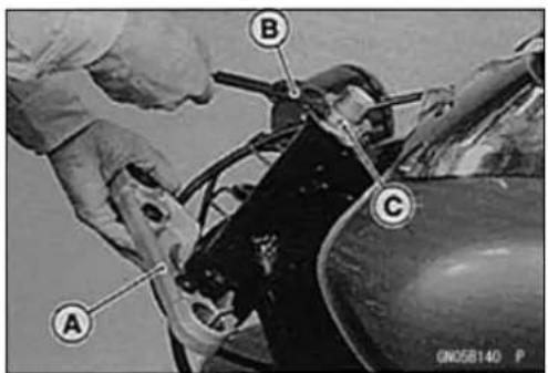
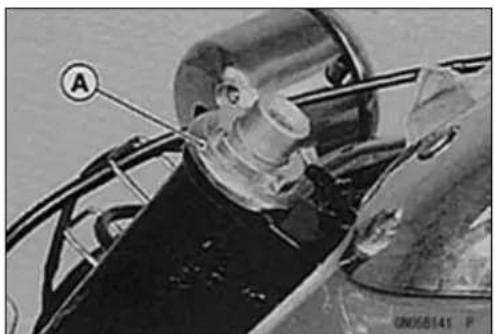
natural_image
Close-up of a person wearing a helmet and safety goggles, with no visible text or symbolsSteeringStem
SteeringStemInstallation
- Applygreasetotheupperandlowerouterracesintheheadpipesothathesteelballswillstickinplaceduringsteminsertion.Installtheuppersteelballs(23)[A]andlowersteelballs(23).Allthesteelballsarethesamesize.
- Putontheupperinnerraceandsteeringstemcap[A]and insertthesteeringstemintotheheadpipe.
-
Installthestemnut[B]sothattherecessedside[C]faces down.
-
Whentheracesarereplacedwithnewones,tightenthe stemnutto20N·m(2.0kgf·m,14.5ft·lb)oftorquewiththe stemnutwrench[A]tosettletheracesinplace.Totighten thestemnuttothespecifiedtorque,hookthewrenchon thestemnut,andpullthewrenchattheholewith108N (11kgf)offorce[B]inthedirectionshown.
- Loosenthestemnutandadjustthesteering(seethis chapter).
• Installtheturnsignallightunit.
○TheleftturnsignallightunithasanLmark[A]onit,andtherightturnsignallightunithasanRmark[B].
○Tighten:
Torque - Turn Signal Light Holder Nuts: 5.9 N·m (0.60 kgf·m, 52in·lb)
- Runthethrottlecables[A], clutchcable[B], andturnsignallightleads[C]asshown. Front[D]
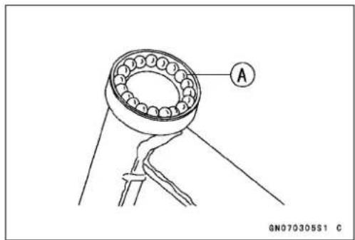


natural_image
Close-up of two black electronic components with labeled parts A and B, shown against a plain background (no readable text or symbols)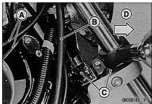
SteeringStem
• Installthefrontfork(seeSuspensionchapter).
NOTE
○ Installthefrontforkatthecorrectposition. Tightenthe forkupperclampbolts[A]first, nextthestemheadbolt [B], lasttheforklowerclampbolts.
Torque-FrontForkClampBolts(Upper):20N·m(2.0 kgf·m,15ft·lb)
SteeringStemHeadBolt:44N·m(4.5kgf·m,33ft·lb)
FrontForkClampBolts(Lower):34N·m(3.5 kgf·m,25ft·lb)
• Installtheremovedparts.
WARNING
Donotimpedethehandlebarturningbyroutingthe cables,harnessesandhosesimproperly(seeGeneralInformationchapter).
- Checkandadjustthefollowingitems.
ThrottleCables(seeFuelSystemchapter)
ClutchCable
RearViewMirrors
- Checkthefrontbrakeeffectiveness.
WARNING
Donotattempttoridethemotorcycleuntilafull brakeleverisobtainedbypumpingthebrakelever untilthepadsareagainstthedisc. Thebrakeswill notfunctiononthefirstapplicationoftheleverif thisisnotdone.
SteeringStemWarp
- Whenever the steering stem [A] is removed, or if the steering cannot be adjusted for smooth action, check the steering stem for straightness.
★Ifthesteeringstemisbent,replacetheeeringstem.

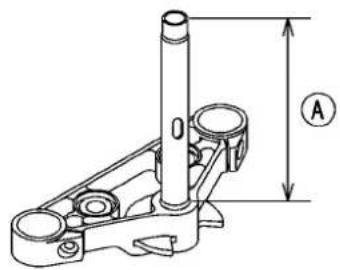
GN050101S1 C
SteeringStemBearing
SteeringStemBearingRemoval
★ Ifthebearingisdamaged,removeit.
- Toremovetheouterraces[A]pressedintheheadpipe, insertabar[C]intotheheadpipe[B], andhammerevenly around the circumference of the oppositer acetodriveit out.
- Hammerthebottom[A]ofthelowerinnerracewitha chisel.
○Usingasuitablebar, pryouttheinnerracefromthestem. GreaseSeal[B] LowerInnerRace[C]


SteeringStemBearingInstallation
- Replacethebearingouterraceswithnewones.
- Applygreasetotheouterraces, and drivetheminto the headpipeatthesametime.
SpecialTools-HeadPipeOuterRacePressShaft:57001 -1075[A]
HeadPipeOuterRaceDriver, 51.5:57001
-1076[C]
HeadPipeOuterRaceDriver, 46.5:57001
-1106[B]

- Replacethestembearinginnerracewithnewones.
- Applygreasetothelowerinnerrace[A], anddriveitonto thestem[B].
SpecialTools-SteeringStemBearingDriver:57001-137 [C]
Steering Stem Bearing Driver Adapter, 34.5:57001-1074[D]

SteeringStemBearingWear, Damage
- Removethesteeringstem(seethischapter).
- Usingahigh-flashpointsolvent, washthe bearings, clean of grease and dirt, and examinetheraces and balls.
- Visuallychecktheballsorraces.
★ Iftheballsorracesareworn, orifeitherraceisdented, replacebothracesandalltheballsforthatbearingasa set.
SteeringStemBearingLubrication
- RefertotheSteeringStemBearingLubricationinthePeriodicMaintenancechapter.
Handlebar
HandlebarRemoval(BN125-A1/A2)
- Remove:
ThrottleCablesA
BrakeMasterCylinderB
LeftHandlebarSwitchHousing[C]
ClutchCableUpperEnd[D]
SpeedometerUnitE
- Removethehandlebarnuts[A]andtakeoffthehandlebar.
HandlebarRemoval(BN125-A3 →)
- Remove:
BrakeMasterCylinderA
RightHandlebarSwitchHousing[B]withThrottleCables[C]
ClutchCableUpperEnd[D]
LeftHandlebarSwitchE
StarterLockoutSwitchLead[F]
- Removethecaps[A]andhandlebarholderclampbolts [B].

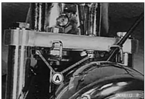
natural_image
Close-up of mechanical components with no visible text or symbols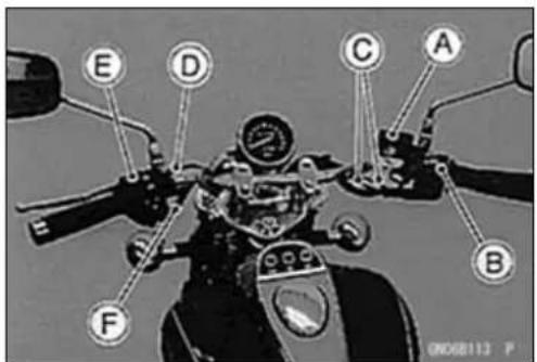

HandlebarInstallation(BN125-A1/A2)
- Tightenthehandlebarnuts.
Torque-HandlebarNuts:34N·m(3.5kgf·m,25ft·lb)
• Installtheremovedparts.
BrakeMasterCylinder(seeBrakeschapter).
Handlebar
- Thefronthalfotherightandleftswitchhousings[A]hasasmallprojection[B].Fittheprojectionintothesmallhole[C]inthehandlebar.
• Installthehandlebarswitchhousing. - Tighten:
Torque - Handlebar Switch Housing Screws: 3.4 N·m (0.35 kgf·m, 30in·lb)
HandlebarInstallation(BN125-A3 \~)
- Thereisagap[A]betweentheupperhandleholderand lowerhandleholdersothatthehandlebarshouldbeinstalledsecurely. Whentheupperholdershallbeinstalled, tightenthefronthhandlebarclampboltsfirstandthenrear boltwithspecifiedtorque.
- Tighten:
Torque-HandlebarHolderClampBolts:20N·m(2.0kgf·m, 15ft·lb)
• Installtheremovedparts.
RearViewMirrorRemoval(Europe)
- Loosenthelowerhexagonalarea[A]fortighteningtoremovetherearviewmirrorfromtheholder.
CAUTION
Donotforcetotightenand/orloosentheupper hexagonalarea(Adapter)[B]withapairofspanners.DisassemblyofthisareaisNotAvailable. Non-permanentlockingagent[D]isalreadyapplied tothethreadsofthisinnerarea.Forciblelooseningmaydamagetheadapterand/ortheturning mechanismofthestay[C].
RearViewMirrorsInstallation(Europe)
- Screwthemountingareaoftherightrearviewmirrorinto theholderalltheway,andtightenthelowerhexagonal areafortighteningsecurely.
[A]LowerHexagonalAreaforTightening
[B]UpperHexagonalArea(Adapter)
[C]RearViewMirror(Right)


natural_image
Close-up of a robotic arm with visible joints and control buttons (no text or symbols)

Frame
TableofContents
Exploded View.... 14-2
Special Tool 14-6
Side Covers 14-7
Left Side Cover Removal 14-7
Left Side Cover Installation 14-7
Right Side Cover Removal.... 14-7
Right Side Cover Installation.... 14-7
Seat 14-8
Seat Removal 14-8
Seat Installation 14-8
Fenders 14-9
Front Fender Removal 14-9
Front Fender Installation 14-9
Rear Fender Rear Removal 14-9
Rear Fender Rear Disassembly.... 14-10
Rear Fender Front Removal 14-10
Frame 14-11
Frame Inspection 14-11

ExplodedView
| No.Fastener | Torque | Remarks | ||
| N·mkgf | mft·lb | |||
| 1FrontFootpegBolts232.317 | ||||
O:Applyoil.
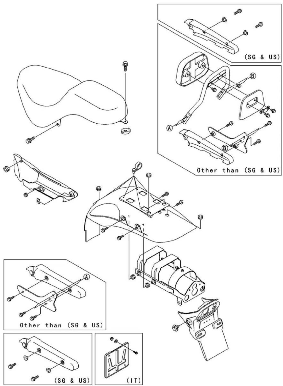
ExplodedView
IT:Italy
SG:Singapore
US:UnitedStates(BN125-A4\~)
Jack: 57001-1238

natural_image
Technical line drawing of a mechanical support structure (no text or symbols)
natural_image
Technical line drawing of a mechanical support structure with springs and mounting brackets (no text or symbols)SideCovers
LeftSideCoverRemoval
- Removethescrews[A].
- Pull[B]thefrontpartoftheleftsidecoveroutwardtoclear thestopper.
- Pull[C]thecoverrearwardtoclearthehook,andremove it.

LeftSideCoverInstallation
- Slipthestopper[A]oftheleftsidecoverontothehook[B].
- Pushthestopperofthecoverintothegrommet.
- Tightenthescrews.

natural_image
Close-up of mechanical components with labeled parts A and B, no readable text or symbols presentRightSideCoverRemoval
- Inserttheignitionswitchkeyintotherightsidecover.
- Turn[A]thekeyclockwise,andpull[B]thefrontpartof thecoveroutwardtoclearthestopper.
- Pull[C]thecoverrearwardtoclearthehook,andremove it.

RightSideCoverInstallation
- Slipthestopper[A]oftherightsidecoverontothehook [B].
- While turning the ignitions switch key clockwise, push the stopper of the cover into the grommet.
- Turnthekeycounterclockwise, andpulloutthekey.

14-8FRAME
Seat
SeatRemoval
- ForthemodelsotherthantheSingaporeandU.S.A.models,removethebolts[A]andloosenthebolts[B]onboth sides.
- Removethepadassembly[C].
- FortheSingaporeandU.S.A.modelsremovethebolts [A],cover[B],andcollar[C]onbothsides. Front[D]
- Removetheseatbolts[A]andtakeofftheseat[B].
SeatInstallation
- Slipthehook[A]oftheseatunderthebracket[B]onthe fueltank.
• Installtheremovedparts.
○FortheSingaporeandU.S.A.models,installthecollar,notingitsdirection(seeabovefigure).


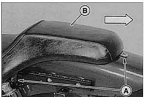

Fenders
FrontFenderRemoval
CAUTION
Becarefulnottoscratchthepainedsurfaceduring removalorinstallation.
- Removethemountingbolts[A]andtakeoffthefront fender[B].
FrontFenderInstallation
- Installthefrontfendersothatthenarrowside[A]faces forward[B].
RearFenderRearRemoval
- Removetheseat(seethischapter).
- Raisetherearwheelofftheground, using the jack (see Wheels/Tireschapter).
SpecialTool-Jack:57001-1238 - Pulltheconnectors[A]oftherearturnsignallightand tail/brakelightleads.
- Removetherearfenderrearbolts[A].
- Pulltherearfenderrear[A]rearward. ○Therearturnsignallightandtail/brakelightleadscome off.

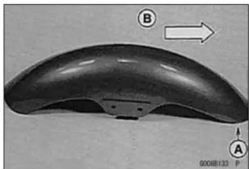
natural_image
Close-up of a curved, smooth object with labeled points A and B, and an arrow indicating direction (no text or symbols on the object itself)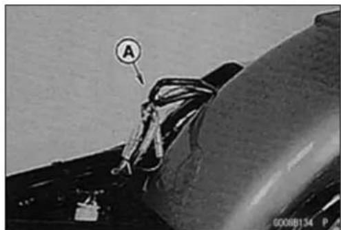

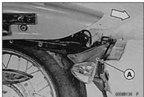
natural_image
Close-up of a car's front wheel assembly with labeled parts and an arrow indicating direction (no readable text or symbols)14-10FRAME
Fenders
RearFenderRearDisassembly
- Removethenuts[A]andtakeofftherearturnsignallight assembly[B].
- Removethenuts[C]andtakeoffthetail/brakelightassembly[D].
RearFenderFrontRemoval
- Remove:
RearFenderRear(seethischapter)
DriveChainClip
RearBrakeRodRearEnd
- Removetherearaxle, and movetherearwheel rearward for the accesstothebolts[A].
- Removetherearfenderfront[A].


natural_image
Close-up of a mechanical component with coiled spring and labeled section A (no readable text or symbols)
Frame
FrameInspection
- Visuallyinspecttheframe[A]forcracks, dents, bending, orwarp.
★ Ifthereisanydamagetotheframe,replaceit.
WARNING
Arepairedframemayfailinuse,possiblycausing anaccident.Iftheframeisbent,dented,cracked,orwarped,replaceit.
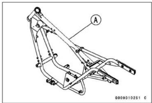
natural_image
Technical line drawing of a mechanical assembly with labeled component A (no text or symbols beyond label)ElectricalSystem
TableofContents
PartsLocation....15-2
ExplodedView....15-4
Specifications....15-10
SpecialToolsandSealant......15-12
WiringDiagram....15-13
Precautions....15-24
Electrical Wiring....15-26
WiringInspection....15-26
Battery....15-27
BatteryRemoval/Installation.....15-27
ElectrolyteSpecificGravity Inspection....15-27
InitialCharging....15-28
OrdinaryCharging....15-29
ChargingSystem....15-31
AlternatorCoverRemoval.....15-31
AlternatorCoverInstallation......15-31
AlternatorRotorRemoval......15-31
AlternatorRotorInstallation......15-32
StatorCoilRemoval....15-32
StatorCoilInstallation....15-33
AlternatorInspection......15-33
Regulator/RectifierInspection.....15-34
ChargingVoltageInspection......15-35
IgnitionSystem....15-38
CrankshaftSensor Removal/Installation....15-38
CrankshaftSensorInspection.....15-38
CrankshaftSensorPeakVoltage Inspection....15-38
IgnitionTimingInspection......15-39
IgnitionCoilRemoval....15-40
IgnitionCoilInstallation....15-40
IgnitionCoilInspection......15-40
IgnitionCoilPrimaryPeak Voltage....15-41
SparkPlugRemoval....15-42
SparkPlugCleaning/Inspection...15-42
SparkPlugGapInspection......15-42
CDIUnitRemoval....15-42
CDIUnitInspection......15-43
ElectricStarterSystem....15-48
StarterMotorRemoval....15-48
StarterMotorInstallation......15-48
StarterMotorDisassembly......15-48
StarterMotorAssembly......15-49
BrushInspection......15-50
CommutatorCleaningand Inspection....15-50
ArmatureInspection......15-50
BrushLeadInspection......15-51
BrushPlateandTerminalBolt Inspection....15-51
StarterRelayInspection......15-51
StarterCircuitRelayInspection...15-52
LightingSystem....15-55
HeadlightBeamHorizontal/VerticalAdjustment....15-55
HeadlightBulbReplacement......15-55
ACLightingVoltageInspection....15-56
Tail/BrakeLightBulb Replacement.....15-58
TurnSignalRelayInspection......15-59
Meter,Gauge,IndicatorUnit....15-63
SpeedometerRemoval......15-63
SpeedometerDisassembly......15-63
IndicatorUnitRemoval/Installation....15-63
BulbReplacement....15-63
SwitchesandSensors....15-64
FrontBrakeLightSwitch Inspection.....15-64
RearBrakeLightTiming Inspection.....15-64
RearBrakeLightTiming Adjustment.....15-64
SwitchInspection....15-64
Fuse....15-65
MainFuse15ARemoval....15-65
MainFuse15AInspection......15-65
Fuse10ARemoval....15-65
Fuse10AInstallation....15-65
Fuse10AInspection....15-66
15-2 ELECTRICAL SYSTEM
PartsLocation


PartsLocation
- Speedometer
- Starterlockoutswitch
- Ignitioncoil
- Startermotor
- Ignitionswitch
6.Crankshaftsensor - Alternator
- Neutralswitch
9.Sidestandswitch
10.Regulator/rectifier
11.Fuseunit
12.Startercircuitrelay - Starterrelay
14.Turnsignalrelay
15.Battery
16.CDlunit
17.Frontbrakelightswitch - Rearbrakelightswitch
ExplodedView

GP02242BW5 C
ExplodedView
| No.F | Fastener | Torque | Remarks | ||
| N·m | kgf·mft·lb | ||||
| 1 | AlternatorCoverBolts | 8.80.9 | 078in·lb | ||
| 2 | StarterMotorMountingBolts8.80.9078in·lb | ||||
| 3 | StarterMotorTerminalLocknut6.90.7061in·lb | ||||
| 4 | StarterMotorAssemblyBolts3.40.3530in·lb | ||||
| 5 | Stator Coil Bolts | 13 | 1.3 | 113 in·lb | |
| 6 | Alternator Lead Holder Bolts (BN125-A1 ~ A2) | 13 | 1.3 | 113 in·lb | |
| Alternator Lead Holder Bolts (BN125-A3 ~) | 8.80.9 | 078in·lb | |||
| 7 | Alternator Rotor Nut (BN125-A1/A2) | 69 | 7.0 | 51 | |
| Alternator Rotor Nut (BN125-A3) | 98 | 10.0 | 72 | ||
| Alternator Rotor Nut (BN125-A4 ~) | 104 | 10.6 | 76 | ||
| 8 | Crankshaft Sensor Screws | 3.9 | 0.40 | 35 in·lb | |
| 9 | IgnitionCoilBolt | 6.90.7 | 061in·lb | ||
| 10 | SparkPlug | 13 | 1.3 | 113 in·lb | |
| 11 | Starter Relay Terminal Bolt | 4.9 | 0.50 | 43 in·lb | |
| 12 | Starter Motor Terminal Nut | 4.9 | 0.50 | 43 in·lb | |
| 13 | Alternator Cover Damper Bolts | 8.8 | 0.90 | 78 in·lb | L |
| 14 | Starter Motor Clutch Bolts (BN125-A1) | 34 | 3.5 | 25 | L |
| 15 | Starter Motor Clutch Bolts (BN125-A2 ~) | 12 | 1.2 | 104 in·lb | L |
| 16 | IgniterMountingScrews | 4.90.5 | 043in·lb | ||
- Crankshaftsensor
- Regulator/rectifier
- Ignition coil
- CDI unit
- Battery
- Starter relay
- Starterclutch (BN125-A1)
- OtherthanUnitedStatesandCanadaModels
EO: Apply engine oil.
L: Applyanon-permanentlocking agent.
M: Applymolybdenumdisulfidegrease.
Si: Applysilicone grease.
SS: Apply silicone sealant (Kawasaki Bond: 56019-120).
ExplodedView

ExplodedView
| No.Fastener | Torque | Remarks | |||
| N·m | kgf·mft·lb | ||||
| 1 | NeutralSwitch | 151.51 | 1 | ||
| 2SidestandSwitchScrews3.90.4035in·lbL | |||||
| 3 | Handlebar Switch Housing Screws | 3.4 | 0.35 | 30 in·lb | |
- Ignitionswitch
- Turnsignal relay
- Startercircuit relay
7.Interlockdiode
8.Fusecase (BN125-A1) - Rearbrake lightswitch
10.Sidestandswitch
11.Meter unit
L: Applyanon-permanentlockingagent.
ExplodedView
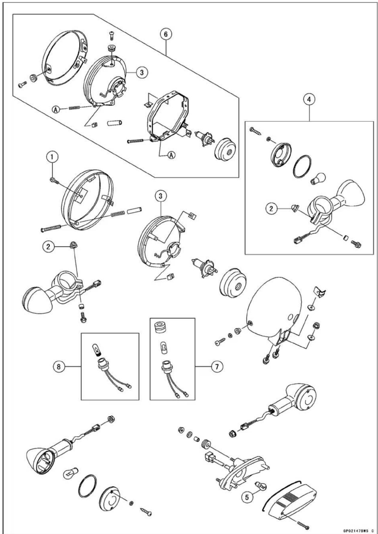
ExplodedView
| No.Fastener | Torque | Remarks | |||
| N·m | kgf·mft·lb | ||||
| 1 | HeadlightBodyScrews | 2.90.30 | 26in·lb | ||
| 2 | Turn Signal Light Holder Nuts | 5.9 | 0.60 | 52 in·lb | |
3.Headlightunit
4. Turnsignallights
5. Tail/brakelight
6.CanadaandUnitedKingdomModels(BN125-A6\~ )
7. Other than Canada and United Kingdom Models
8. United Kingdom Model only (BN125-A6\~ )
Specifications
| ItemStandardServiceLimit | ||
| BatteryCapacity12V9Ah-- --ElectrolyteLevelbetweenlevellines-- -SpecificGravityofElectrolyte1.280±0.01@20°C(68°F)-- -- | ||
| ChargingSystemType:(BN125-A1/A2)Single-phaseAC-- -(BN125-A3 ~) Charging Voltage Stator Coil Resistance Regulator/rectifier:Type:(BN125-A1/A2)(BN125-A3 ~) Resistance Single-phase all wave rectifier Three-phase all wave rectifier in the text | ||
| ACLightingSystemAlternatorType:(BN125-A1/A2)Single-phaseAC(BN125-A3 ~) AC Lighting Voltage LightingCoilResistance:(BN125-A1/A2)(BN125-A3 ~) | Three-phase AC11 ~ 16 V @engine speed 4 000 r/min (rpm) | --- |
| --- | ||
| --- | ||
| --- | ||
| --- | ||
| --- | ||
| IgnitionSystemCrankshaftSensorResistance:(BN125-A1/A2)(BN125-A3 ~) Crankshaft Sensor Peak Voltage IgnitionCoil:3 Needle Arcing Distance Primary Winding Resistance Secondary Winding Resistance Primary Peak Voltage SparkPlug:SparkPlugType:Standard Option Spark Plug Gap Spark Plug Cap Resistance | 180 ~ 280 Ω (× 100 Ω)190 ~ 290 Ω (× 100 Ω)3.6 V or more6 mm or more0.09 ~ 0.13 Ω (× 1 Ω)3.8 ~ 5.8 kΩ (× 1 kΩ)110 V or moreNGK CR7ENGK CR8E or ND U24ESR-N0.7 ~ 0.8 mm (0.028 ~ 0.031 in.)3.75 ~ 6.25 kΩ (× 1 kΩ) | --- |
| --- | ||
| --- | ||
| --- | ||
| --- | ||
| --- | ||
| --- | ||
| --- | ||
| --- | ||
| --- | ||
| --- | ||
| --- | ||
| --- | ||
| --- | ||
| --- | ||
| ElectricStarterSystemStarterMotor:BrushLength Commutator Diameter | 9.5 ~ 10.5 mm (0.37 ~ 0.41 in.)27.95~ 28.05mm(1.10~ 1.11in.) | 8 mm (0.31 in.)27mm(1.06 in.) |
Specifications
| ItemStandardServiceLimit | |
| SwitchesRearBrakeLightSwitchTimingONafterabout10mm(0.39in.)pedaltravel | -- -- |
SpecialToolsandSealant
FlywheelPuller, M30×1.5: 57001-1191

natural_image
Technical line drawing of a mechanical component with a hexagonal top and cylindrical base (no text or symbols)RotorPuller, M16/M18/M20/M22×1.5: 57001-1216

natural_image
Technical illustration of a mechanical assembly with threaded components and a cylindrical component (no text or symbols)TimingLight: 57001-1241

natural_image
Line drawing of a handheld electronic device with coiled cable and connector (no text or symbols)Spark Plug Wrench, Hex 16: 57001-1262

natural_image
Line drawing of a T-shaped tool with a cylindrical end and two protruding pins (no text or symbols)FlywheelHolder: 57001-1313

natural_image
Technical line drawing of a mechanical clamp or measuring tool (no text or symbols present)HandTester: 57001-1394

natural_image
Technical line drawing of a mechanical housing or enclosure with internal components and mounting holes (no text or symbols)PeakVoltageAdapter: 57001-1415

natural_image
Pure electrical circuit lines without any symbolsKawasakiBond(SiliconeSealant): 56019-120

WiringDiagram
DummyPage
BN125-A1
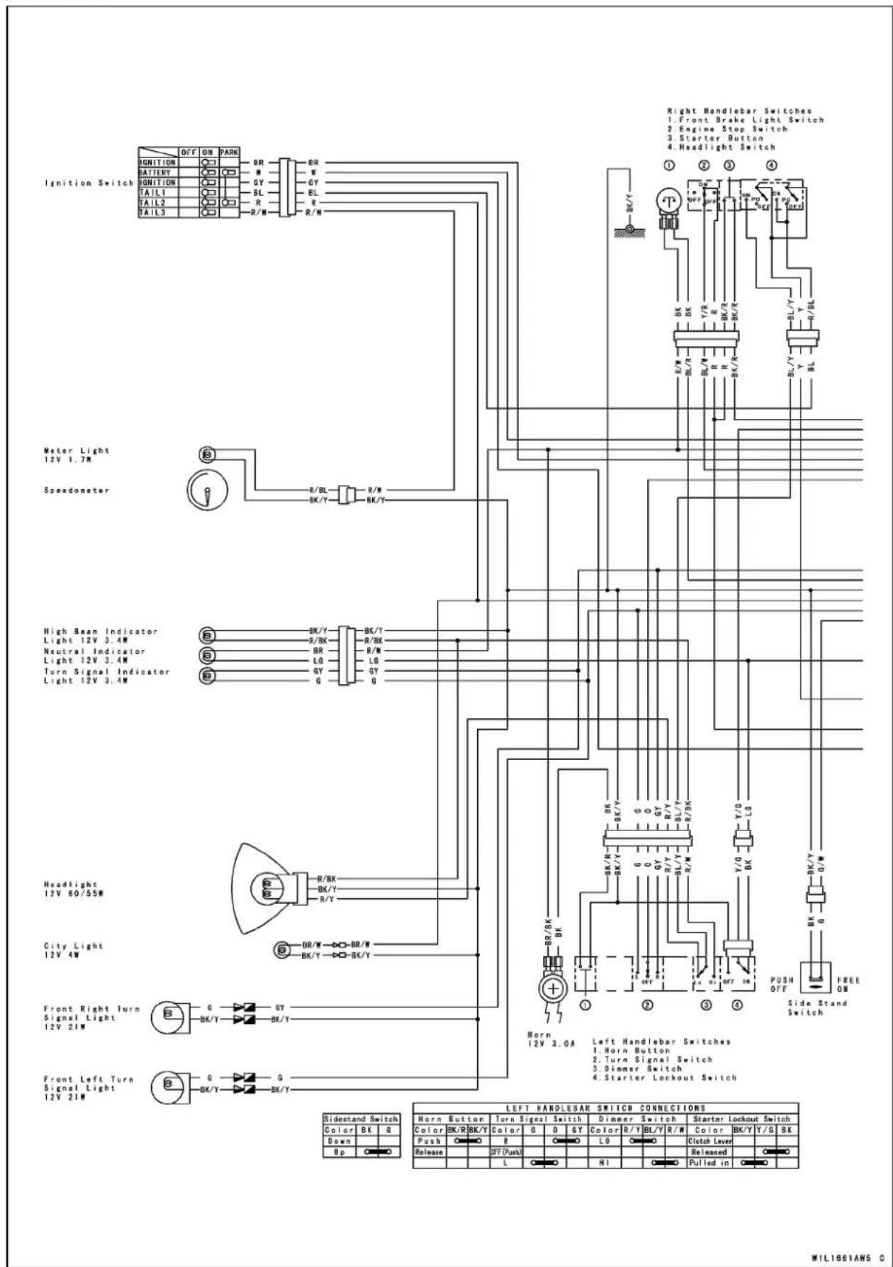
WIL1861AW5 C
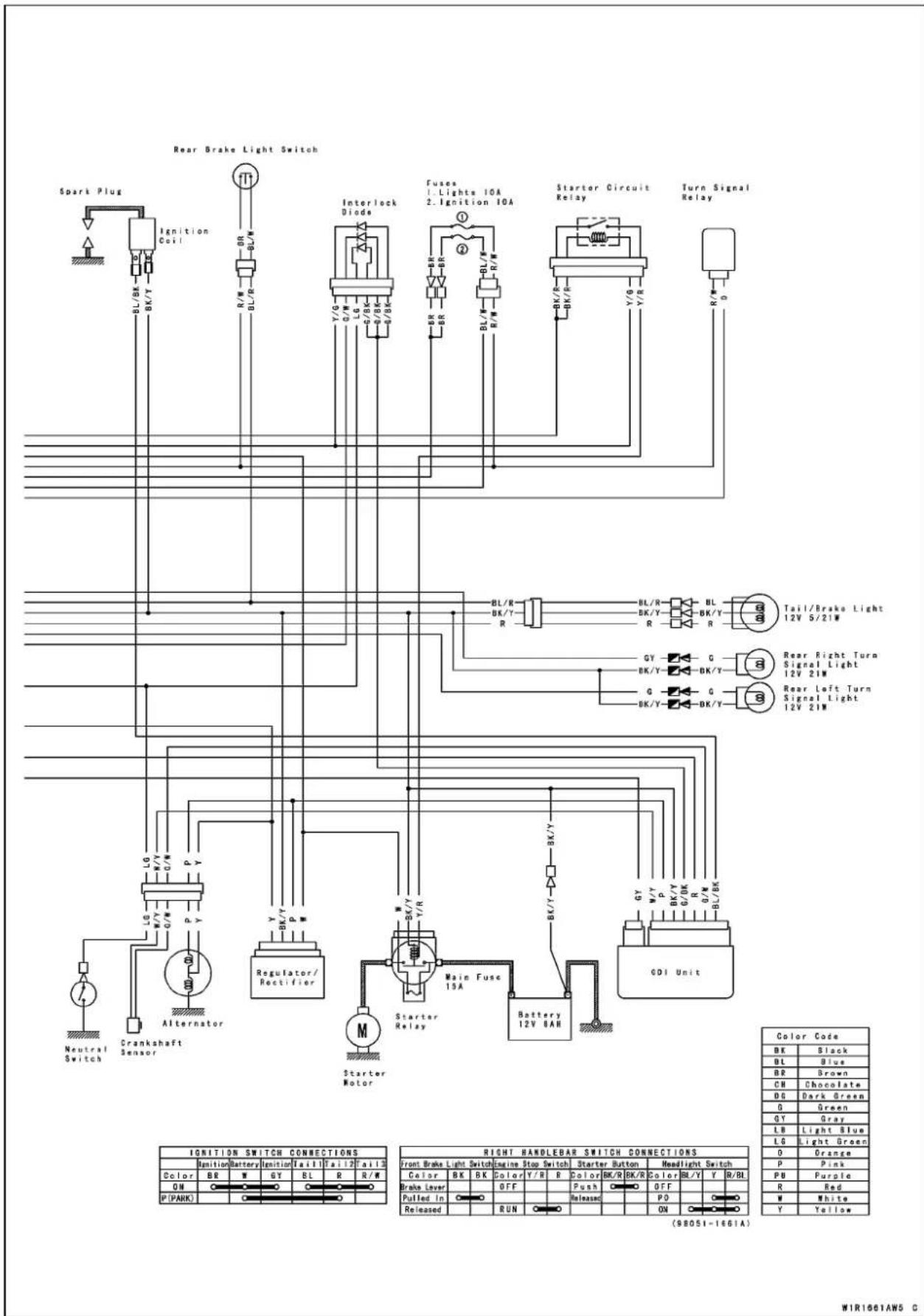
W1R1661AW5 C
BN125-A2\~ (Singapore) and BN125-A4 (United States)

WiringDiagram

W1R1783CW5 C
BN125-A2\~ A5(Europe)


W1R1784CW5 C
BN125-A5(UnitedStatesandCanada)
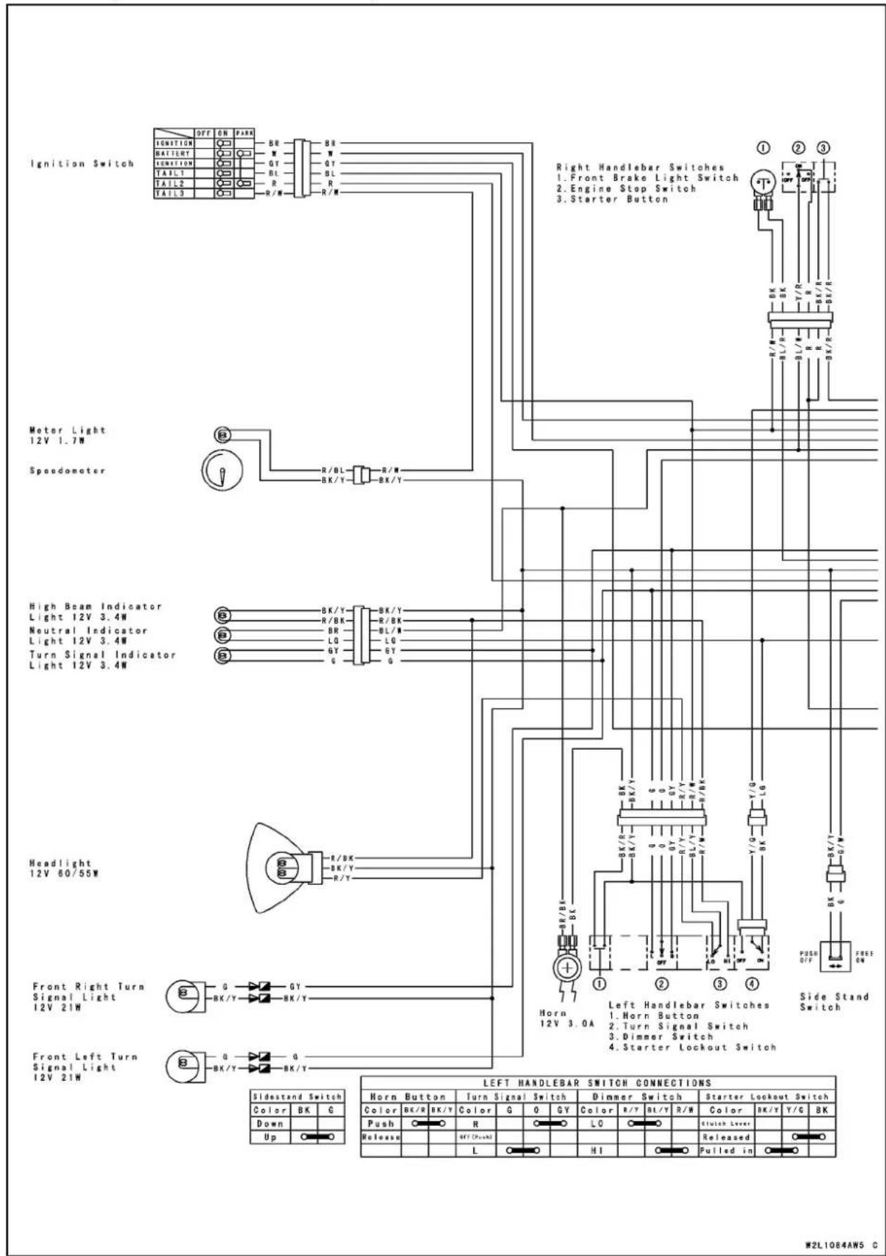
BN125-A6\~ (US,CA,N,NU)

WiringDiagram

W2R0138AW5 C
Precautions
Thereare anumberofimportantprecautionsthatare mustswhenservicingelectricalsystems.Learnandobservealltherulesbelow.
○Donotreversethebatterycableconnections. This will burnoutthediodesontheelectricalparts.
○Alwayscheckbatteryconditionbeforecondemningother partsofanelectricalsystemAfullychargedbatteryisa mustforconductingaccurateelectricalsystemtests.
○Theelectricalpartsshouldneverbestrucksharply,as withahammer,orallowedtofallonahardsurface.Such ashocktothepartscandamagethem.
○Topreventdamagetoelectricalparts,donotdisconnect thebatterycablesoranyotherelectricalconnections whentheignitionswitchison,orwhiletheengineis running.
○Becauseofthelargeamountofcurrent,neverkeepthe starterbuttonpushedwhenthestartermotorwillnotturn over,orthecurrentmayburnoutthestartermotorwindings.
- Donotuseameterorindicatorilluminationbulbrated forotherthanvoltageorwattagespecifiedinthewiring diagram, asthemeterorindicatorpanelcouldbewarped byexcessiveheatradiatedfromthebulb.
○Takecarenottoshorttheleadsthataredirectlyconnectedtothebatterypositive(+)terminaltothechassis ground.
○Troublesmayinvolveoneorinsomecasesallitems. Neverreplaceadefectivepartwithoutdeterminingwhat CAUSEDthefailure.Ifthefailurewascausedbysome otheritemoritems,theytoomustberepairedorreplaced, orthenewreplacementwillsoonfailagain.
○Makesureallconnectorsinthecircuitarecleanandtight, andexaminewiresforsignsofburning,fraying,etc.Poor leadsandbadconnectionswillaffectelectricalsystem operation.
○Measurecoilandwindingresistancewhenthepartiscold (atroomtemperature).
○ColorCodes:
BK:Black
BL:Blue
BR:Brown
CH:Chocolate
DG:Darkgreen
G:Green
GY:Gray
LB:Lightblue
LG:Lightgreen
O:Orange
P:Pink
PU:Purple
R:Red
W:White
Y:Yellow
Precautions
ElectricalConnectors Connectors[A]

natural_image
Technical line drawing of two electronic components with labeled terminals (no text or symbols beyond labels)Connectors[B]
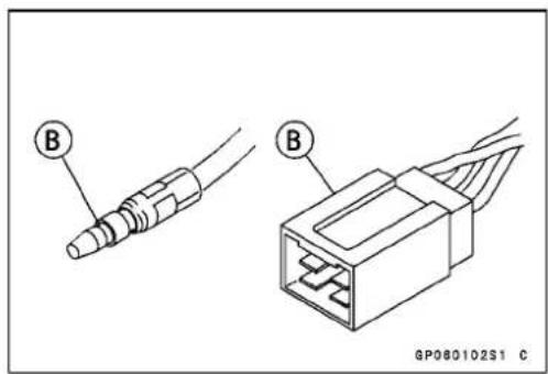
- Visuallyinspectthewiringforsignsofburning,fraying, etc.
★Ifanywiringispoor,replacethedamagedwiring. - Pulleachconnector[A]apartandinspectitforcorrosion, dirt,loosenessanddamage.
★ Iftheconnectoriscorrodedordirty, cleanitcarefully. Ifit isdamaged, replace it. - Checkthewiringforcontinuity.
○Usethewiringdiagramtofindtheendsoftheleadwhich issuspectedofbeingaproblem.
○Connectthehandtesterbetweentheendsoftheleads.
SpecialTool-HandTester:57001-1394
○Setthetestertothe×1Ω range,andreadthetester.
★If the tester does not read 0 Ω, the lead is defective. Re-placetheleadorthewiringharness[B]ifnecessary.

flowchart
graph TD
    A["Device 1"] --> B["Component B"]
    B --> C["Device 2"]
    C --> D["Component D"]
    D --> E["Device 3"]
    E --> F["Component F"]
    F --> G["Device 4"]
    G --> H["Component H"]
    H --> I["Device 5"]
    I --> J["Component J"]
    J --> K["Device 6"]
    K --> L["Component L"]
    L --> M["Device 7"]
    M --> N["Component N"]
    N --> O["Device 8"]
    O --> P["Component P"]
    P --> Q["Device 9"]
    Q --> R["Component R"]
    R --> S["Device 10"]
    S --> T["Component T"]
    T --> U["Device 11"]
    U --> V["Component V"]
    V --> W["Device 12"]
    W --> X["Component X"]
    X --> Y["Device 13"]
    Y --> Z["Component Z"]
Battery
BatteryRemoval/Installation
- Remove:
RightSideCover(seeFramechapter) BatteryHolder
- Disconnectthebatterynegative(−)cable[A]first,and then the positive(+)cable[B]. Front[C]
- Wheninstallingthebattery,connectthepositive(+)cable [A]firstandthenthenegativecable[B].
CAUTION
If the batterycable is not correctly disconnected or connected, sparkscanariseate electrical connections, causing damage to electrical parts.
ElectrolyteSpecificGravityInspection
- Checkbatteryconditionbytestingthespecificgravityof theelectrolyteineachcellwithahydrometer[A].
○Readtheleveloftheelectrolyte[B]onthefloatingscale.
★ If the specific gravity is below 1.200, the battery need to be charged.
NOTE
○ Thespecificgravityoftheelectrolytevarieswith changesintemperature, sothespecificgravityreading mustbecorrectedforthetemperatureoftheelectrolyte.
○Celsius:Add0.007pointstoreadingforeach10°C (50°F)above20°C(68°F)orsubtract0.007pointsfor each10°Cbelow20°C(68°F).
○Fahrenheit:Add0.004pointstoreadingforeach-12°C (10°F)above10°C(68°F)orsubtract0.004pointsfor each-12°C(10°F)below10°C(68°F).
★ If the specific gravity of any of the cells is more than 0.050 away from any other reading, the battery will probably not accept a charge. It is generally best to replace the battery in this condition.
★ If the specific gravity of all the cells is 1.280 or more, the battery is fully charged.
When using the hydrometer, read the electrolyte level at the bottom of themeniscus (curved surface of the fluid).
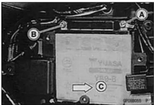


Battery
InitialCharging

WARNING
Keepthebatteryawayfromsparksandopenflames duringcharging,sincethebatterygivesoffanexplosivegasmixtureofhydrogenandoxygen.When usingabatterycharger,connectthebatterytothe chargerbeforeturningonthecharger.Thisprocedurepreventssparksatthebatteryterminalswhich couldigniteanybatterygases.
- Removethebattery(seethischapter).
- Filleachcelltotheupperlevellineonthebatterycasewith freshelectrolyte(specificgravity:1.280)atatemperature of 30^(86^) orless.Letthebatterystandforabout30 minutesbeforecharging.
NOTE
○ Iftheelectrolyteleveldrops, addelectrolytetotheupper levellinebeforecharging.
- Setthechargingrateat1/10thebatterycapacity,and chargeitfor10hours.Thebatteryisratedat9Ah,and therecommendedchargingrateis0.9A.
CAUTION
Ifthebatteryisnotgivenafullinitialcharging, it willdischargeinafewweeks. Afterthatitcannot bechargedbysupplementalcharging. Alwaysremovethebatteryfromthevehiclefor charging. Ifthebatteryischargedwhilestillinstalled, batteryelectrolytemayspillandcorrode theframeorotherpartsofthevehicle. Donotuseahighratebatterycharger, asistypicallyemployedatautomotiveservicestations, unlesssthechargerratecanbereducedtothelevelrequired. Chargingthebatteryataratehigherthan specifiedmayruinthebattery. Chargingatahigh ratecausesexcessheatwhichcanwarptheplates andcauseinternalshorting. Higher-than-normal chargingratesalsocausetheplatestoshedactive material. Depositswillaccumulate, andcancause internalshorting. Ifthetemperatureoftheelectrolyterisesabove 45°C(113°F)duringcharging, reducethecharging ratetolowerthetemperature, andincreasechargingtimeproportionately.
- Turnthechargeroff, thendisconnectitfromthebattery.
- Checkbatteryvoltage.Batteryvoltageshouldbe12\~ 13 V.

line
| Battery Charge (%) | Specific Gravity | |---|---| | 0 | 1.08 | | 10 | 1.20 | | 20 | 1.12 | | 40 | 1.16 | | 60 | 1.20 | | 80 | 1.24 | | 100 | 1.28 | Full Charge 1.28 (20°C) GP080101S1 CBattery
OrdinaryCharging
- Removethebattery(seeBatteryRemoval).
- Ifanyofthecellsarelow,fillthemtotheLOWERlevel linewithdistilledwateronly.Theelectrolytewillexpand duringcharging,andthelevelwillrise.
WARNING
Keepthebatteryawayfromsparksandopenflames duringcharging,sincethebatterygivesoffanexplosivegasmixtureofhydrogenandoxygen.When usingabatterycharger,connectthebatterytothe chargerbeforeturningonthecharger.Thisprocedurepreventssparksatthebatteryterminalswhich couldigniteanybatterygases.
- ConnectachargertothebatteryBEFOREpluggingitinorturningiton.
- Setthechargingrateandtimeaccordingtothebattery conditionpreviouslydetermined,usingtheBatteryChargingRate/TimeTable.
- Checktheelectrolytelevelaftercharging.
CAUTION
Alwaysremovethebatteryfromthevehiclefor charging. If the battery is charged while still installed, battery electrolyte may spill and corrode the frame or other part of the vehicle. Donot use a high rate battery charger, asistypically employed data automotiveservices stations, unless the chargerrate can be reduced to the level required. Charging the battery at a rate higher than specified may ruin the battery. Charging at a high rate causes excess heat which can warp the plates and cause internal shorting. Higher-than-normal charging rates also cause the plate tested active material. Deposits will accumulate, and can cause internal shorting. If the temperature of the electrolyterises above 45°C (113°F) during charging, reduce the charging rate to lower the temperature, and increase charging time proportionately.
- Turnthechargerofforunplugit, thendisconnectit from thebattery.
- Checkbatterycondition.
★ If the battery condition indicates that it is not fully charged, additional charging time is necessary.
Battery
BatteryChargingRate/TimeTable(12V9Ah)

line
| Specific Gravity | Hours of Charging Time at Rates Shown | | ---------------- | ------------------------------------- | | 1.280 | 7.6-9.5 | | 1.140 | 1.080 | | At 1A charge rate | 6.75 | | At 2A charge rate | 4.5 | | At 3A charge rate | 4.5 |GP08017BW2 C
ChargingSystem
AlternatorCoverRemoval
- Draintheengineoil(seeEngineLubricationSystem chapter).
- Remove: EngineSprocketCover(seeFinalDrivechapter) AlternatorLeadConnector[A]
- Remove: AlternatorCoverBolts[A] AlternatorCover[B]
- Removethetorquelimiter[A].
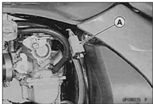
natural_image
Close-up of a car's engine compartment with labeled component A (no readable text or symbols beyond label)
natural_image
Close-up of a mechanical component with labeled parts A and B, showing internal structure and wiring (no readable text or symbols)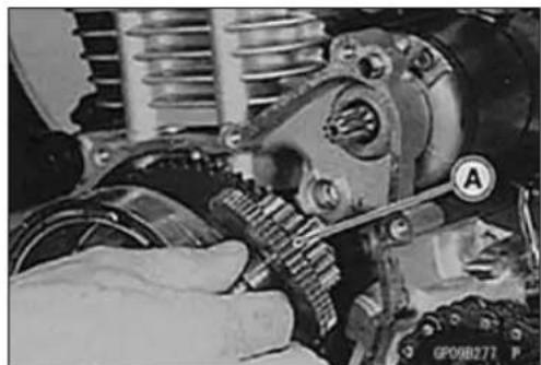
natural_image
Close-up of a mechanical assembly with gears and springs, no visible text or symbolsAlternatorCoverInstallation
- Install:
DowelPins[A]
NewGasket[B] - Applymolybdenumdisulfidegreasetothestarterpinion gear[C]andtorquelimitershaft[D].
- Routetheleadscorrectly(seeAppendixchapter).
- Tighten:
Torque-AlternatorCoverBolts:8.8N·m(0.90kgf·m,78 in·lb)
- Pourtheengineoil(seeEngineLubricationSystemchapter).

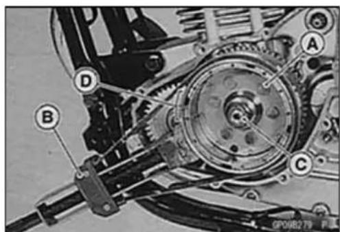
AlternatorRotorRemoval
- Removethealternatorcover(seethischapter).
- Wipeoilofftheoutercircumferenceoftherotor.
- Holdthealternatorrotor[A]steadywiththeflywheel holder[B],andremovetherotornut[C].
SpecialTool-FlywheelHolder:57001-1313
CAUTION
Donotholdthetimingplate[D]ofthealternator rotor. This candamagethetimingplate.
ChargingSystem
- Usingtheflywheelpuller[A]androtorpuller[B],remove thealternatorrotor[C]fromthecrankshaft. SpecialTools-FlywheelPuller,M30×1.5:57001-1191 RotorPuller,M16/M18/M20/M22×1.5:57001 -1216
○Holdingtheflywheelpuller, screwintherotorpullerwhile tappingtheheadoftherotorpullerwithahammerand removethealternatorrotor.
- Removethestartergear[D].
AlternatorRotorInstallation
- Applyoiltothecrankshaftjournal[A].
- Usingacleaningfluid,cleanoffanyoilordirtonthefollowingportionsanddrythemwithacleancloth. CrankshaftTaperedPortion[B] AlternatorRotorTaperedPortion[C]
• Installthestartergear[A].
- Installthewoodruffkey[B]securelyintheslotofthe crankshaft.
- Installthealternatorrotor[D]sothatthewoodruffkeyfits inthegroove[C]oftherotor.
- Tighten:
Torque-AlternatorRotorNut (BN125-A1/A2):69N·m(7.0kgf·m,51ft·lb) (BN125-A3):98N·m(10.0kgf·m,72ft·lb) (BN125-A4\~):104N·m(10.6kgf·m,76ft·lb)
SpecialTool-FlywheelHolder:57001-1313
• Installthealternatorcover(seethischapter).
StatorCoilRemoval
- Remove: AlternatorCover(seethischapter) StatorCoilBolts[A] CrankshaftSensorScrews[B] Holders[C]
- Removethestatorcoil[D]andthecrankshaftsensorE fromthealternatorcover.


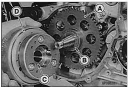

ChargingSystem
StatorCoilInstallation
- Tighten:
Torque-StatorCoilBolts[A]:13N·m(1.3kgf·m,113in·lb)
CrankshaftSensorScrews[B]:3.9N·m(0.40 kgf·m,35in·lb)
AlternatorLeadHolderBolts
(BN125-A3\~):8.8N·m(0.90kgf·m,78in·lb)
(BN125-A1\~A2):13N·m(1.3kgf·m,113in·lb)
- Applysiliconesalanttothecircumferenceofthealternatorleadgrommet[C],andfitthegrommetintothenotch ofthecoversecurely.
Sealant-KawasakiBond(SiliconeSealant):56019-120
AlternatorInspection
Therearethreetypesofalternatorfailures:short,open (wireburnedout),orlossinrotormagnetism.Ashortor openinoneofthecoilwireswillresultineitheralowoutput, ornooutputatall.Alossinrotormagnetism,whichmaybe causedbydroppingorhittingthealternator,byleavingit nearanelectromagneticfield,orjustbyaging,willresultin lowoutput.
- Tocheckthealternatoroutputvoltage,dothefollowing procedures.
○ Disconnectthealternatorconnector[A]. Usinganauxiliarywires, connectthefollowingleadsintheconnectors forengineoperation.
L/G←→ L/G
W/Y←→ W/Y
G/W←→ G/W
○Connectthehandtesterasshowninthetable.
○ Starttheengine.
○Runitat4000r/min(rpm)oftheenginespeed.
○Notethevoltagereadings.
SpecialTool-HandTester:57001-1394
AlternatorOutputVoltage(BN125-A1/A2)
| Meter Range | Connections | Reading @4000rpm | |
| Meter (+) to | Meter (-) to | ||
| 50VAC | Pink lead | Engine ground | 37 V or more |
AlternatorOutputVoltage(BN125-A3\~)
| Meter Range | Connections | Reading @4000rpm | |
| Meter (+) to | Meter (-) to | ||
| 250 V AC | Yellow lead | Yellow lead | 38 V or more |
★If the output voltage shows the value in the table, the alternatoroperatesproperly.Amuchlowerreadingthanthe valueinthetableindicatesthatthealternatorisdefective.


ChargingSystem
- Checkthestatorcoilresistanceasfollows.
○Stoptheengine.
○Connectthehandtesterasshowninthetable.
○Notetheresistancereadings.
StatorCoilResistance(BN125-A1/A2)
| Tester Range | Connections | Reading | |
| Meter(+)toMeter(-) to | |||
| × 1 | PinkleadEngineground | 0.1~0.8Ω | |
StatorCoilResistance(BN125-A3\~)
| Tester Range | Connections | Reading | |
| Meter(+)toMeter(-) to | |||
| ×1Ω | YellowleadYellowlead | 0.3~0.9Ω | |
★Ifthereismoreresistancethanshowninthetable,orno handtesterreading(infinity),thestatorhasanopenlead andmustbereplaced.Muchlessthanthisresistance meansthestatorisshorted,andmustbereplaced.
★If the stator coil has normal resistance, but the voltage check showed the alternator to be defective, then the rotor magnetshaveprobablyweakened,andtherotor mustbe replaced.
Regulator/RectifierInspection
- Remove: RightSideCover(seeFramechapter) Regulator/Rectifier[A]
- Disconnecttheconnector[B]fromtheregulator/rectifier.
- Set the hand tester to the × 1 kΩ range and make the measurementsshowninthetable.
SpecialTool- HandTester: 57001-1394
★If the tester readings are not as specified, replace the regulator/rectifier.
CAUTION
UseonlyHandTester57001-1394forthistest.A tester other than the Kawasaki Hand Tester may showdifferentreadings. Ifamuggerorameterwithalarge-capacitybattery isused,theregulator/rectifierwillbedamaged.
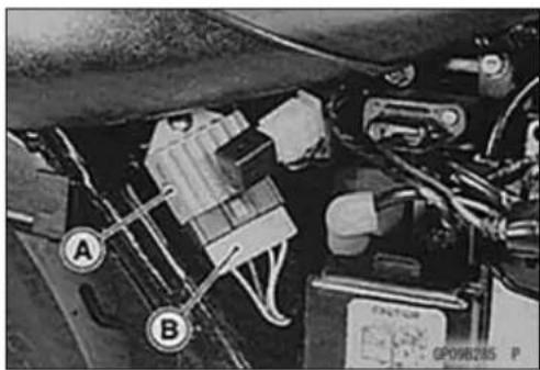
Regulator/RectifierInternalResistance(BN125-A1/A2)
Unit:kΩ
(-)*: Tester(-)LeadConnection

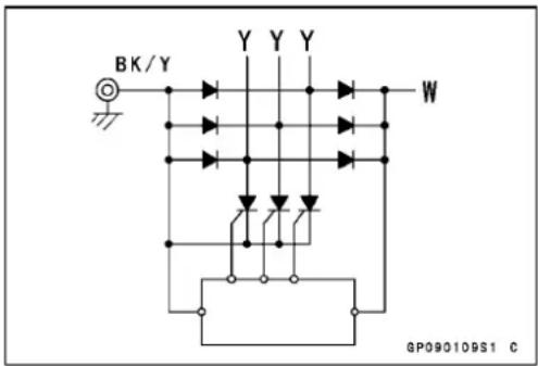
Charging Voltage Inspection
- Check the battery condition (see Battery section).
- Warm up the engine to obtain actual alternator operating conditions.
- Check that the ignition switch is turned off, and connect the hand tester as shown in the table.
Special Tool - Hand Tester: 57001-1394
Charging Voltage
| Tester Range | Connections | Reading | |
| Tester (+) to | Tester (−) to | ||
| 25 V DC | Battery (+) | Battery (−) | 14 ~ 15 V |
- Turn on the ignition switch and start the engine, and note the voltage readings at various engine speeds with the headlight turned on and then turned off. The readings should show nearly battery voltage when the enginespeedislow,andastheenginespeedrises,the readingsshouldalsorise. Buttheymustbekeptunder thespecifiedvoltage.
- Turn off the ignition switch to stop the engine, and disconnectthehandtester.
★ If the charging voltage is kept between the values given in the table, the charging system is considered to be working normally.
★ If the output voltage is much higher than the values specified in the table, theregulator/rectifier is defective or the regulator/rectifier leads are loose or open.
★If the charging voltage does not rise as the engine speed increases, then the regulator/rectifier is defective or the alternatoroutputisinsufficientforthe loads. Checkthe alternatorandregulator/rectifiertodeterminewhichpart isdefective.
ChargingSystemCircuit(BN125-A1/A2)
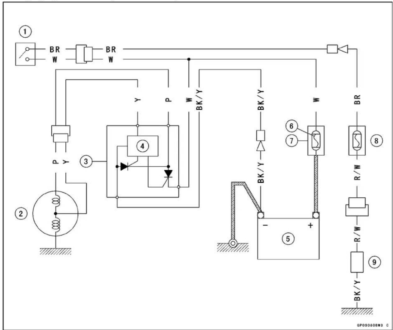
flowchart
graph TD
    A["①"] --> B["BR W"]
    B --> C["BR W"]
    C --> D["②"]
    D --> E["③"]
    E --> F["④"]
    F --> G["P Y"]
    G --> H["⑤"]
    H --> I["+"]
    I --> J["⑥"]
    J --> K["⑦"]
    K --> L["BR R/W"]
    L --> M["⑧"]
    M --> N["R/W"]
    N --> O["⑨"]
    O --> P["BK/Y"]
    P --> Q["-"]
    Q --> R["⑤"]
    R --> S["⑥"]
    S --> T["W"]
    T --> U["BK/Y"]
    U --> V["W"]
    V --> W["BK/Y"]
    W --> X["BK/Y"]
    X --> Y["BK/Y"]
    Y --> Z["BK/Y"]
    Z --> AA["BK/Y"]
    AA --> AB["BK/Y"]
    AB --> AC["BK/Y"]
    AC --> AD["BK/Y"]
    AD --> AE["BK/Y"]
    AE --> AF["BK/Y"]
    AF --> AG["BK/Y"]
    AG --> AH["BK/Y"]
    AH --> AI["BK/Y"]
    AI --> AJ["BK/Y"]
    AJ --> AK["BK/Y"]
    AK --> AL["BK/Y"]
    AL --> AM["BK/Y"]
    AM --> AN["BK/Y"]
    AN --> AO["BK/Y"]
    AO --> AP["BK/Y"]
    AP --> AQ["BK/Y"]
    AQ --> AR["BK/Y"]
    AR --> AS["BK/Y"]
    AS --> AT["BK/Y"]
    AT --> AU["BK/Y"]
    AU --> AV["BK/Y"]
- Ignitionswitch
- Alternator
- Regulator/rectifier
- Controller
5.Battery
6.Mainfuse15A - Starterrelay
8.Lightfuse10A
9.Load
ChargingSystem
ChargingSystemCircuit(BN125-A3\~)

- Ignitionswitch
- Alternator
- Regulator/rectifier
4.Battery
5.Mainfuse30A - Starterrelay
7.Lightfuse15A
8.Load
IgnitionSystem
CDIUnitConnectors[A]
CAUTION
Donotdisconnectthebatterycablesoranyother electricalconnectionswhentheignitionswitchis on,orwhiletheengineisrunning. This is to prevent CDlunitdamage.Donotinstallthebatterybackwards.Thenegativesideisgrounded.This is to prevent damage to the diodes and CDlunit.
WARNING
Theignitionsystemproducesextremelyhighvoltage.Donottouchthesparkplug,ignitioncoilwhile theengineisrunning,oryoucouldreceiveasevere electricalshock.
CrankshaftSensorRemoval/Installation
- RefertotheStatorCoilRemoval/InstallationintheElectricalSystemchapter.
CrankshaftSensorInspection
- Removethealternatorleadconnector[A].
- Setthehandtestertothe×100Ω rangeandmeasure theresistancebetweentheG/WandW/Yleadterminals inthefemaleconnector.
SpecialTool-HandTester:57001-1394
★ Ifthereismoreresistancethanthespecifiedvalue,the coilhasanopenleadandmustbereplaced.Muchless thanthisresistancemeansthecoilisshorted,andmust bereplaced.
CrankshaftSensorResistance BN125-A1/A2:180\~280Ω
BN125-A3\~:
190\~290Ω
- Using the highest resistance range of the tester, measure the resistance between the G/Wand W/Y lead in the female connector and chassis ground.
★Any tester reading less than infinity ( ) indicates a short, necessitating replacement of the crankshaft sensor assembly.
CrankshaftSensorPeakVoltageInspection
NOTE
○Besurethebatteryisfullycharged.
○ Usingthepeakvoltageadapterisamorereliableway todeterminetheconditionofthecrankshaftsensorthan crankshaft sensorinternal resistancemeasurements.
- Remove:
RightSideCover(seeFramechapter) - Disconnectthe crankshaftsensorconnector[A].

natural_image
Close-up of an electronic device with visible components and wiring (no readable text or symbols)
natural_image
Close-up of a mechanical engine component with labeled parts (A) and no visible text or symbols beyond the label.
natural_image
Close-up of a car engine bay with visible wiring and battery (no text or symbols)IgnitionSystem
- Setthehandtester[B]tothe×25VDCrange, and connectittothepeakvoltageadapter[C]asshowninthe diagram.
- ConnecttheblackleadoftheadaptertoW/Yleadandred leadtoG/Wleadinthecrankshaftsensorconnector[A].
- Turntheignitionswitch.
- Pushingthestarterbutton,turntheengine4\~5 secondswiththetransmissiongearinneutraltomeasurethe crankshaftsensorpeakvoltage.
- Repeatthemeasurement5ormoretimes.
CrankshaftSensorPeakVoltage
Standard: 3.6Vormore
SpecialTools-HandTester:57001-1394
PeakVoltageAdapter:57001-1415
Type: KEK-54-9-B
★ Ifthetesterreadingisnotspecifiedone, checkthecrank-shaftsensor.
CAUTION
Donotdisconnectthebatterycablesoranyother electricalconnectionswhentheignitionswitchis on,orwhiletheengineisrunning. Thisoprevent CDlunitdamage.Donotinstallthebatterybackwards.Thenegativesideisgrounded.Thisisto preventdamagetothediodesandCDlunit.
WARNING
Theignitionsystemproducesextremelyhighvoltage. Donottouchthesparkplug,ignitioncoil,or sparkplugleadwhiletheengineisrunning,oryou couldreceiveasevereelectricalshock.
IgnitionTimingInspection
- Removethecamshaftchaincover(seeEngineTopEnd chapter).
- Attachthetiminglight[A]inthemannerprescribedbythe manufacturer.
SpecialTool- TimingLight:57001-1241 - Starttheengineandaimthetiminglightattheignition timingmarkonthecamshaftsprocket[B].
- Runtheengineatthespeedspecifiedandnotethealignmentoftheignitiontimingmarks.
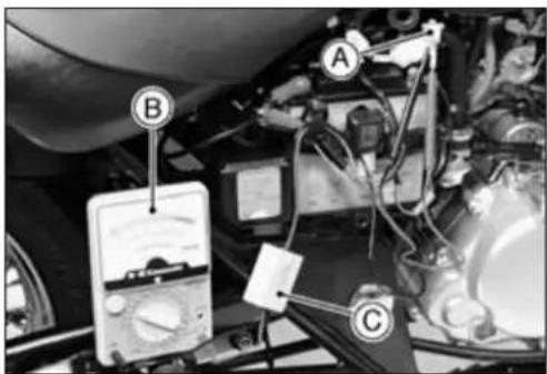

IgnitionSystem
IgnitionTiming
| EnginespeedHeadtiming | mark[A]alignswith: |
| 1 300 ±100 r/min (rpm) | “T” mark [B] on camshaft sprocket |
★Iftheignitiontimingisincorrect,inspecttheCDlunitand thecrankshaftsensor.
IgnitionCoilRemoval
- Removethefueltank(seeFuelSystemchapter).
- Disconnecttheprimarywindingleadsfromtheignition coil.
- Removethemountingbolt[A].
• Takeofftheignitioncoil[B].
IgnitionCoilInstallation
- Tightentheignitioncoilbolt.
Torque-IgnitionCoilBolt:6.9N·m(0.70kgf·m,61in·lb)
○Installtheignitioncoilnotingthepositionoftheground terminal[A],andprimarywindingleads.
(+) Terminal[B] BL/BKLead
(-) Terminal [C] → BK/Y Lead
IgnitionCoilInspection
- Removetheignitioncoil(seethischapter).
- Measure the arcing distance with the suitable commercially available coil tester [A] to check the condition of the ignition coil [B].
- Connecttheignitioncoil(withthesparkplugcapleftattachedattheendofthesparkpluglead)tothetesterin themannerprescribedbythemanufacturerandmeasure thearcingdistance.
WARNING
Toavoidextremelyhighvoltageshocks, donot touchthecoilbodyorleads.
★If the distance reading is less than the specified value, the ignitioncoilorsparkplugcapsdefective.
IgnitionCoilArcingDistance:6mmormore
- Todeterminewhichpartisdefective,measurethearcing distanceagainwiththesparkplugcapremovedfromthe ignitioncoil.Removethecapbyturningitcounterclockwise.
★Ifthearcingdistanceissubnormalasbefore,thetrouble iswiththeignitioncoilitself. Ifthearcingdistanceisnow normal,thetroubleiswiththesparkplugcap.
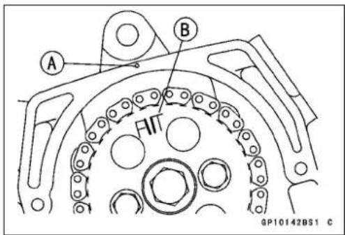


IgnitionSystem
★ Ifthecolltesterisnotavailable, thecoilcanbechecked forabrokenorbadlyshortedwindingwiththehandtester.
NOTE
○Thehandtestercannotdetectlayershortsandshorts resultingfrominsulationbreakdownunderhighvoltage.
- Measure the primary winding resistance as follows.
○Connectthehandtesterbetweenthecoilterminals.
- Measurethesecondarywindingresistanceasfollows.
○Removetheplugcap.
○Connectthetesterbetweenthesparkplugleads.
Measureprimarywindingresistance[A]. Measuresecondarywindingresistance[B]. IgnitionCoil[C]
★ Ifthetesterdoesnotreadasspecified, replacethecoil.
IgnitionCoilWindingResistance
| Primary Windings: | 0.09 ~ 0.13 Ω (× 1 Ω) |
| Secondary Windings: | 3.8 ~ 5.8 kΩ (× 1 kΩ) |
- Visually inspect these secondary winding lead.
★ Ifitshowsanydamage, replacethecoil.
IgnitionCoilPrimaryPeakVoltage
NOTE
○Besur ethebatteryisfullycharged.
- Removethefueltank(seeFuelSystemchapter).
- Removethesparkplugcap.
- Measuretheignitioncoilprimarypeakvoltageasfollows;
- Installthenewsparkplug[A]intotheremovedsparkplug cap[F]andgrounditontotheengine.
- Connectthepeakvoltageadapter[B]intothehandtester [C]andsetittothe×250VDCrange.
Adapterblacklead→ Ignitioncoilprimaryleadterminal [D]
Adapterredlead→ Ignitioncoilgroundterminal IgnitionCoilE
Battery[G]
CDIUnit(ICIgniter)[H]

WARNING
To avoid extremely high voltage shock, do not touch the spark plugort ester connection.
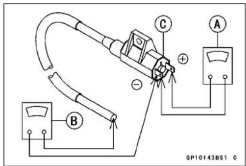
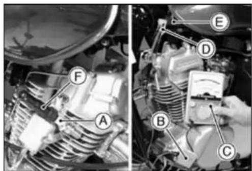
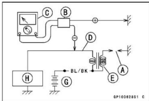
IgnitionSystem
- Turntheignitionswitchandenginestopswitchon.
- Pushing the starter button, turn the engine 4 \~ 5 seconds with the transmission gear in neutral to measure the ignition coil primary peak voltage.
- Repeatthemeasurement5ormoretimes.
IgnitionCoilPrimaryPeakVoltage
Standard: 110Vomore
SpecialTools-HandTester:57001-1394
PeakVoltageAdapter:57001-1415
Type:KEK-54-9-B
★Ifthereadingislessthanthespecifiedvalue,checkthe following; IgnitionCoil(seeIgnitionCoilInspection) CrankshaftSensor(seeCrankshaftSensorInspection) CDIUnit(seeCDIUnitInspection)
SparkPlugRemoval
- Removethesparkplugcap.
- Removethesparkplugusingthe16mmplugv
SpecialTools-SparkPlugWrench,Hex16:57001-1262or
Owner's Tool:92110-1172
![A Arenon [A] OP108293 P](/content/2026/05/1077878/images/dffae8155f943c724e935c936fe317e4b99d2e58dbc1159b71bc26e201c7ae40.jpg)
SparkPlugCleaning/Inspection
- RefertotheSparkPlugCleaning/InspectioninthePeriodicMaintenancechapter.
SparkPlugGapInspection
- RefertotheSparkPlugGapInspectioninthePeriodic Maintenancechapter.
CDIUnitRemoval
ThehandtestercanchecktheCDIunitforabrokenor badlyshortedwinding, butitisashortcutmethodwhich cannot inspect the precise condition of the CDIunit.
- Remove: FuelTank(seeFuelSystemchapter) CDIUnitscrews[A]andBolts[B] CDIUnit[C]
- DisconnecttheconnectorsfromtheCDlunit.

IgnitionSystem
CDIUnitInspection
CAUTION
When inspecting the CDIUnit[A], observethefollowing to avoid damage to the CDIUnit. Donot disconnect the CDIUnit with the ignition switch on. This may damage the CDIUnit. Donot disconnect the battery leads while the engine is running. This may damage the CDIUnit.
CDIUnitOperationCheck
- Removethefueltank(seeFuelSystemchapter).
- Disconnecttheconnectors[A]fromtheCDIUnit.
- Setthehandtester[B]tothe25VDCrange,andconnect ittotheconnectorcomefromharnesssideasfollows.
Tester(+)terminal[D]→ Rlead Tester(-)terminal[C]→ BK/Ylead
SpecialTool-HandTester:57001-1394
- Turntheignitionswitchon, andreadthevoltage.
CDIUnitOperationVoltage:BatteryVoltage
★ If the tester reading is not specified one, check the battery voltage, ignition switch and ignition fuse.
- Setthehandtestertothe×1kΩ rangeandmakethe measurementsshowninthetable.
SpecialTool-HandTester:57001-1394
★ Ifthetesterreadingsarenotasspecified, replacetheCDI unit.
CAUTION
UseonlyHandTester57001-1394forthistest.A testerother thantheKawasakiHandTestermay showdifferentreadings.
Ifameggerormeterwithalarge-capacitybatteryis used,theCDIunitwillbedamaged.

natural_image
Close-up of a motorcycle's internal electronic component with visible wiring and connectors (no readable text or symbols)
GP100627S1 C
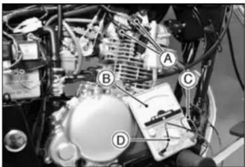

GP100102S1 C
CDIUnitInternalResistance(BN125-A1/A2)Unit:kΩ
(-)*: Tester(-)LeadConnection
CAUTION
UseonlyHandTester57001-1394forthistest. A tester other than the Kawasaki Hand Tester may showdifferentreadings. If a megger or meter with a large-capacity battery is used, the CDlunitwillbedamaged.

CDI Unit Internal Resistance (BN125-A3 \~)
Unit: kΩ
| Tester(+)LeadConnection | ||||||||||||
| Terminal | 1 | 2 | 3 | 4 | 5 | 6 | 7 | 8 | 9 | 10 | ||
| (-)* | 1 | - | 30~150 | 92.5~370 | 30~150 | 80~320 | 32.5~160 | 55~220 | 67.5~270 | 30~150 | 6.5~26 | |
| 2 | ∞ | - | 24~96 | 0 | 8~38 | 0.5~2 | 3.3~13 | 7~28 | 0 | 4.5~18 | ||
| 3 | ∞ | 24.5~98 | - | 24.5~98 | 47.5~190 | 25~100 | 26.5~106 | 40~160 | 47.5~198 | 33~132 | ||
| 4 | ∞ | 0 | 24~96 | - | 9.5~38 | 0.5~2 | 3~12 | 7~28 | 0 | 4.5~18 | ||
| 5 | ∞ | ∞ | ∞ | ∞ | - | ∞ | ∞ | ∞ | ∞ | ∞ | ||
| 6 | ∞ | 0.5~2 | 24.5~98 | 0.5~2 | 10~40 | - | 6.5~26 | 7.5~30 | 0.5~2 | 5.3~21 | ||
| 7 | ∞ | 5~20 | 26.5~106 | 5~20 | 18.5~74 | 5.5~22 | - | 12~48 | 5~20 | 11~44 | ||
| 8 | ∞ | 500~2000 | 500~2000 | 500~2000 | 750~3000 | 500~2000 | 500~2000 | - | 500~2000 | 500~2000 | ||
| 9 | ∞ | 0 | 24~96 | 0 | 9.5~38 | 0.5~2 | 3.5~14 | 7~28 | - | 5~20 | ||
| 10 | ∞ | 20~96 | 70~280 | 20~92 | 55~220 | 20~96 | 20~130 | 45~180 | 19.5~92 | - | ||
(-)*: Tester(-)LeadConnection
IgnitionSystem
IgnitionSystemTroubleshooting

flowchart
graph TD
    A["Faulty Ignition (Malfunctioned engine)"] -->|Good| B["Ignition System Wiring and Connector Inspection"]
    B -->|No Good| C["Repair or Replace"]
    B -->|Good| D["Crankshaft Sensor Inspection"]
    D -->|No Good| E["Replace"]
    D -->|Good| F["Crankshaft Sensor Peak Voltage Measurement"]
    F -->|No Good| G["Replace Faulty Parts"]
    F -->|Good| H["Ignition Coil Inspection"]
    H -->|No Good| I["Replace"]
    H -->|Good| J["Ignition Coil Peak Voltage Measurement"]
    J -->|No Good| K["Adjust or Replace"]
    J -->|Good| L["Spark Plug Gap Inspection"]
    L -->|No Good| M["Adjust or Replace"]
    L -->|Good| N["CDI Unit Inspection"]
    N -->|No Good| O["Replace CDI Unit"]
    N -->|Good| P["CDI Unit Operation"]
    P -->|No Good| Q["Replace Faulty Parts"]
    P -->|Good| R["Inspect: 1. Peak Voltage Adapter\n2. Crankshaft Sensor Connector\n3. Battery Voltage"]
    R -->|No Good| S["Replace Faulty Parts"]
    R -->|Good| T["Inspect: 1. Peak Voltage Adapter\n2. Ignition Coil Connector\n3. Battery Voltage"]
    T -->|No Good| U["Replace Faulty Parts"]
    T -->|Good| V["Inspect: 1. Battery Voltage\n2. Ignition Switch\n3. Ignition Fuse"]
    V -->|No Good| W["Replace CDI Unit"]
IgnitionSystemCircuit(BN125-A1/A2)

flowchart
graph TD
    A["①"] --> B["②"]
    B --> C["③"]
    C --> D["④"]
    D --> E["⑤"]
    E --> F["⑥"]
    F --> G["⑦"]
    G --> H["⑧"]
    H --> I["⑨"]
    I --> J["⑩"]
    J --> K["⑪"]
    K --> L["⑫"]
    L --> M["⑬"]
    M --> N["⑭"]
    N --> O["⑮"]
    O --> P["⑯"]
    P --> Q["⑰"]
    Q --> R["⑱"]
    R --> S["⑲"]
    S --> T["⑳"]
    T --> U["㉑"]
    U --> V["㉒"]
    V --> W["㉓"]
    W --> X["㉔"]
    X --> Y["㉕"]
    Y --> Z["㉖"]
    Z --> AA["㉗"]
    AA --> AB["㉘"]
    AB --> AC["㉙"]
    AC --> AD["㉚"]
    AD --> AE["㉛"]
    AE --> AF["㉜"]
    AF --> AG["㉝"]
    AG --> AH["㉟"]
    AH --> AI["㉟A"]
    AI --> AJ["㉟B"]
    AJ --> AK["㉟C"]
    AK --> AL["㉟D"]
    AL --> AM["㉟E"]
    AM --> AN["㉟F"]
    AN --> AO["㉟G"]
    AO --> AP["㉟H"]
    AP --> AQ["㉟I"]
    AQ --> AR["㉟J"]
    AR --> AS["㉟K"]
    AS --> AT["㉟L"]
    AT --> AU["㉟M"]
    AU --> AV["㉟N"]
    AV --> AW["㉟O"]
    AW --> AX["㉟P"]
    AX --> AY["㉟Q"]
    AY --> AZ["㉟R"]
    AZ --> BA["㉟S"]
    BA --> BB["㉟T"]
    BB --> BC["㉟U"]
    BC --> BD["㉟V"]
    BD --> BE["㉟W"]
    BE --> BF["㉟X"]
    BF --> BG["㉟Y"]
    BG --> BH["㉟Z"]
- Neutralswitch
- Interlockdiodes
3.Sidestandswitch - Starterlockoutswitch
5.Enginestopswitch
6.Ignitionfuse10A - Ignitionswitch
- Regulator/rectifier
9.Crankshaftsensor
10.CDlunit
11.Ignitioncoil
12.Sparkplug
13.Battery
14.Mainfuse15A
IgnitionSystem
IgnitionSystemCircuit(BN125-A3\~)

flowchart
graph TD
    A["①"] --> B["BR W GY"]
    B --> C["BR W GY"]
    C --> D["BR W GY"]
    D --> E["②"]
    E --> F["BK/Y Y/G BK"]
    F --> G["BK"]
    G --> H["G/W W/Y"]
    H --> I["Y/G G/W LG"]
    I --> J["G/BK G/BK"]
    J --> K["③"]
    K --> L["G/W W/Y"]
    L --> M["④"]
    M --> N["G/W LG"]
    N --> O["G/BK G/BK"]
    O --> P["⑤"]
    P --> Q["BK G"]
    Q --> R["G/W"]
    R --> S["⑥"]
    S --> T["BR BL/W R BL/W"]
    T --> U["R BL/W"]
    U --> V["⑦"]
    V --> W["⑧"]
    W --> X["LG"]
    X --> Y["⑨"]
    Y --> Z["⑩ BL/BK BK/Y"]
    Z --> AA["⑪"]
    AA --> AB["⑫"]
    AB --> AC["W"]
    AC --> AD["⑭"]
    AD --> AE["⑮"]
    AE --> AF["⑯"]
    AF --> AG["⑪"]
    AG --> AH["W"]
    AH --> AI["⑭"]
    AI --> AJ["⑮"]
    AJ --> AK["W"]
    AK --> AL["⑭"]
    AL --> AM["⑮"]
    AM --> AN["W"]
    AN --> AO["⑭"]
    AO --> AP["W"]
    AP --> AQ["⑭"]
- Ignitionswitch
- Starterlockoutswitch
3.Crankshaftsensor
4.Interlockdiodes
5.Sidestandswitch
6.Ignitionfuse15A
7.Enginestopswitch - Neutralswitch
9.CDlunit
10.Ignitioncoil
11.Sparkplug
12.Mainfuse30A
13.Battery
14.Regulator/rectifier
ElectricStarterSystem
StarterMotorRemoval
CAUTION
Donottapthestartermotorshaftorbody. Tapping theshaftorbocoulddamagethemotor.
- Remove:
OilPipe(seeEngineLubricationSystemchapter) - Slidebacktherubbercap.
- Removethestartermotorterminalnut[A].
- Removetheartermotormountingbolts[B].
- Pulloutthestartermotor[C].
StarterMotorInstallation
CAUTION
Donottapthestartermotorshaftorbody. Tapping theshaftorbody could damage themotor.
- Wheninstallingthestartermotor,cleanthestartermotorlegs[A]andcrankcase[B]wherethestartermotoris grounded.
- ReplacetheO-ring[A]withanewone.
- ApplyasmallamountofengineoiltotheO-ring.
• Installthestartermotor. - Tighten:
Torque-StarterMotorMountingBolts:8.8N·m(0.90kgf·m, 78in·lb)
StarterMotorTerminalNut:4.9N·m(0.50kgf·m, 43in·lb)
StarterMotorDisassembly
- Removethestartermotor(seethissection).
- Takeoffthestartermotorassemblybolts[A]andremove bothendcovers[B]andpullthearmatureoutoftheyoke.


natural_image
Close-up mechanical assembly showing a component with labeled parts A and B, no readable text or symbols present.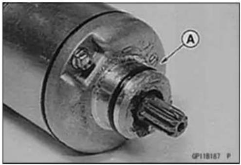
natural_image
Close-up of a mechanical component with labeled section A (no readable text or symbols beyond label)
ElectricStarterSystem
- Removetheterminallocknut[A]andterminalbolt[B], and thenremovethebrushwiththebrushplatefromtheyoke.
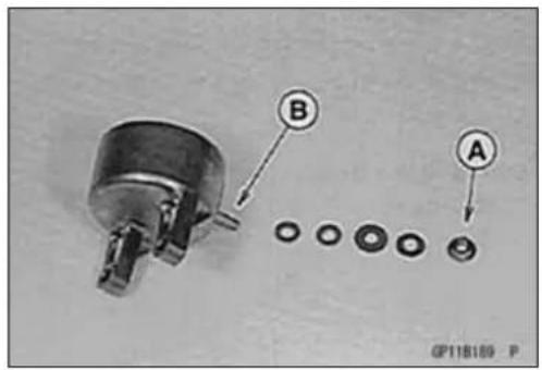
StarterMotorAssembly
- ReplacetheO-ringswithnewones.
- Applyathincoatofgreasetotheoilseal[A]andneedle bearing[B].
- Fitthetoothedwasher[C]intotheendcover.

- Installthebrushplate[A]andtightentheterminallocknut [B].
Torque-StarterMotorTerminalLocknut:6.9N·m(0.70 kgf·m,61in·lb)
- Fitthetongue[C]onthebrushplateintotheendcover groove.

- Insertthearmature[A]betweenthebrushes.

natural_image
Close-up of hands assembling a mechanical component with a labeled section (A), no visible text or symbols.- Alignthemarks[C]ontheyoke[B]andendcovers[A].
- Tightenthestartermotorassemblybolts.
Torque-StarterMotorAssemblyBolts:3.4N·m(0.35 kgf·m,30in·lb)

ElectricStarterSystem
BrushInspection
• Measurethelength[A]ofeachbrush.
★Ifanyisworndowntotheservicelimit, replacethecarbon brushholderassembly[B].
StarterMotorBrushLength
Standard: 9.5 \~ 10.5 mm (0.37 \~ 0.41 in.)
ServiceLimit:8mm(0.31in.)
CommutatorCleaningandInspection
- Smooththecommutatorsurface[A]ifnecessarywithfine emerycloth[B],andcleanoutthegrooves.
- Measurethediameter[A]ofthecommutator[B].
★ If the commutator diameter is less than the servicelimit, replace the starter motor with anewone.
CommutatorDiameter
Standard: 27.95 \~ 28.05 mm (1.10 \~ 1.11 in.)
ServiceLimit:27mm(1.06in.)
ArmatureInspection
- Usingthe×1Ω handtesterrange,measuretheresistancebetweenanytwocommutatorsegments[A].
SpecialTool-HandTester:57001-1394
★Ifthereisahighresistanceornoreading(∞)betweenany twosegments, awindingisopenandthestartermotor mustbereplaced.
- Using the highest and test range, measure the resistance between these segments and the shaft [B].
★ If there is any reading at all, the immature has a short and the starter motorm must be replaced.
NOTE
Eveniftheforegoingchecksshowthearmaturetobe good,itmaybedefectiveinsomemannernotreadily detectablewiththehandtester.Ifallotherstartermotor andstartermotorcircuitcomponentscheckgood,but thestartermotorstilldoesnotturnoveroronlyturns overweakly,replacetheartermotorwithanewone.
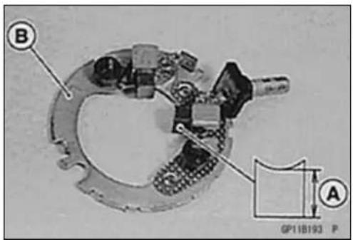
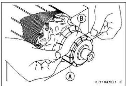


ElectricStarterSystem
BrushLeadInspection
- Usingthe×1Ω handtesterrange,measuretheresistanceasshown.
TerminalBoltandPositiveBrush[A]
BrushPlateandNegativeBrush[B]
SpecialTool-HandTester:57001-1394
★ If there is not closeto 0Ω, the brush has an open. Re-placetheterminal bolt assembly and/or the brush holder assembly.
BrushPlateandTerminalBoltInspection
- Using the highest and testerrange, measure the resistance as shown.
TerminalBoltandBrushPlate[A]
TerminalBoltandNegativeBrushHolder[B]
TerminalBoltandEndCover[C]
SpecialTool-HandTester:57001-1394
★ Ifthereisanyreading, thebrushholderassembly and/or terminalboltassembly haveashort. Replacethebrush holderassembly and theterminalboltassembly.
StarterRelayInspection
- Remove:
RightSideCover(seeFramechapter)
StarterCircuitRelay
- Connectthehandtester[A]and12Vbattery[B]tothe starterrelay[C]asshown.
SpecialTool-HandTester:57001-1394
★ Iftherelaydoesnotworkasspecified,therelayisdefective.Replacetherelay.
TestingRelay
TesterRange: ×1Ω range
Criteria: When battery is connected → 0Ω
When battery is disconnected → ∞ Ω
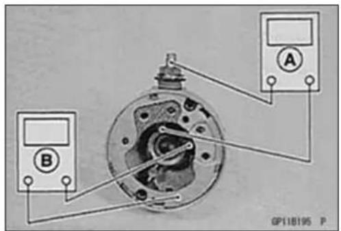


ElectricStarterSystem
StarterCircuitRelayInspection
- Remove:
RightSideCover(seeFramechapter)
StarterCircuitRelay
- Connectthehandtester[A]and12Vbattery[B]as shown.
RelayCoilTerminal[1]and[2]
RelaySwitchTerminal[3]and[4]
★Iftherelay[C]doesnotworkasspecified,therelayis defective.Replacetherelay.
SpecialTool-HandTester:57001-1394
TestingRelay
TesterRange:×1Ω range
Criteria: When battery is connected → 0Ω
When battery is disconnected → ∞ Ω
StarterCircuitRelay[A]
StarterRelay[B]
InterlockDiodes[C]
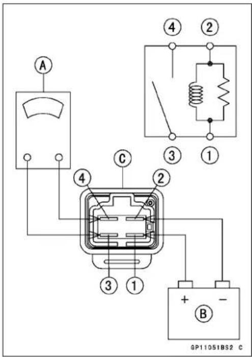

ElectricStarterSystem
ElectricStarterCircuit(BN125-A1/A2)

- Ignitionswitch
2.Enginestopswitch - Starterbutton
- Startercircuitrelay
- Ignition fuse 10A
- Starterlockoutswitch
7.Interlockdiodes
8.CDlunit - Startermotor
- Starterrelay
11.Mainfuse15A
12.Battery
13.Neutralswitch
ElectricStarterCircuit(BN125-A3\~)
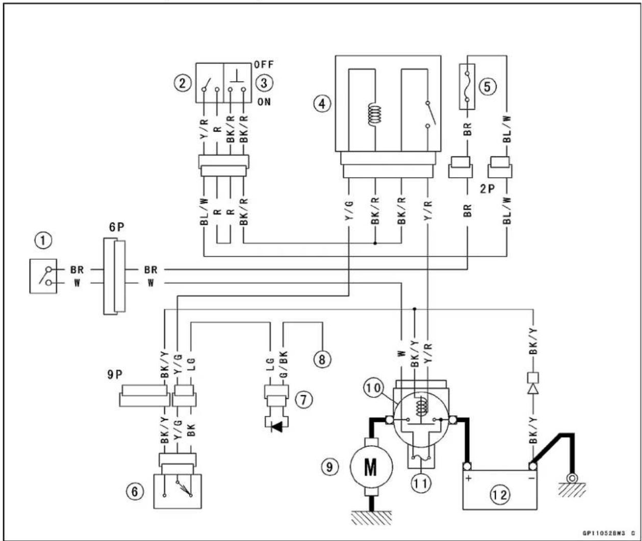
- Ignitionswitch
2.Enginestopswitch - Starterbutton
- Startercircuitrelay
- Ignitionfuse15A
- Starterlockoutswitch
7.InterlockDiodes
8.CDlunit - Startermotor
- Starterrelay
11.Mainfuse30A
12.Battery
LightingSystem
HeadlightBeamHorizontal/VerticalAdjustment
- Turnthehorizontaladjuster[A]ontheheadlightwitha screwdriverinoroutuntilthebeampointsstraightahead.
○Turnthehorizontaladjusterclockwisetofacethehead-lightleft. - Turntheverticaladjuster[B]ontheheadlightinoroutto adjusttheheadlightvertically.
○Turntheverticaladjusterclockwisetofacetheheadlight up.
NOTE
○Onhighbeam, the brightestpointsshouldbeslightly below horizontal with themotorcycleonitswheels and theriderseated. Adjust the headlight to the proper angle according to local regulations.
HeadlightBulbReplacement
- Removetheheadlightrimscrews[A].
- Pulltheheadlightunit[B]anddropitout.
- Remove: BulbSocket[A] DustCover[B]
- Removethehook[A].

natural_image
Close-up of a motorcycle's headlight with labeled points A and B (no text or symbols beyond labels)
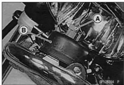
natural_image
Close-up of mechanical components with labeled parts A and B, no readable text or symbols present
natural_image
Close-up of a mechanical component with circular features and labeled parts (no readable text or symbols)LightingSystem
- Replacetheheadlightbulb[A].
CAUTION
Whenhandlingthequartz-halogenbulb,never touchtheglassportionwithbarehands.Always useacleancloth.Oilcontaminationfromhandsor dirtyragscanreducebulblifeorcausethebulbto explode.
NOTE
○ Cleanoffanycontaminationthatinadvertentlygetson thebulbwithalcoholorsoapandwatersolution.
- Fitthedustcover[A]withthe"TOP"mark[B]upwardonto thebulbfirmlyasshown.
- Installtheheadlightunit[B]withthe"TOP"mark[A]upward. - Afterinstallation,adjusttheheadlightaim(seethischapter).
ACLightingVoltageInspection
- Removetheheadlightunit(seethischapter).
○Donotremovethebulbsocket. - Connectthehandtester[A]totheR/BKandBK/Yleads inthesocketasshowninthetable.
- PushtheheadlightswitchtoONanddimmerswitchtoHI.
- Runtheengineat4000r/min(rpm)andmeasurethe voltage.
ACLightingVoltage
| Tester Range | Connections | Rearing @4000rpm | |
| Tester(+)oTester(-)b | |||
| 25 V AC | R/BK lead | BK/Y lead | 11~ 16V |
- Stoptheengine.
★If the voltage is kept between the values given in the table, thelightingsystemisconsideredtobeworkingnormally.
★Ifthevoltageismuchhigherthanthevaluesspecifiedin thetable,theregulator/rectifierisdefectiveortheregulator/rectifierleadsarelooseoropen.
★ If the voltage is much lower than the value specified in the table, theregulator/rectifier is defective or alternator output is insufficient. Check theregulator/rectifier and alternator to determine which part is defective.

natural_image
Close-up of a hand adjusting a mechanical component with a labeled section (A), no visible text or symbols.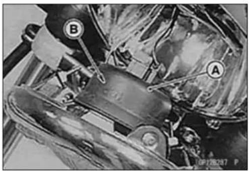
natural_image
Close-up of mechanical components with labeled parts A and B, no readable text or symbols present

LightingSystem
HeadlightCircuit(BN125-A1/A2)
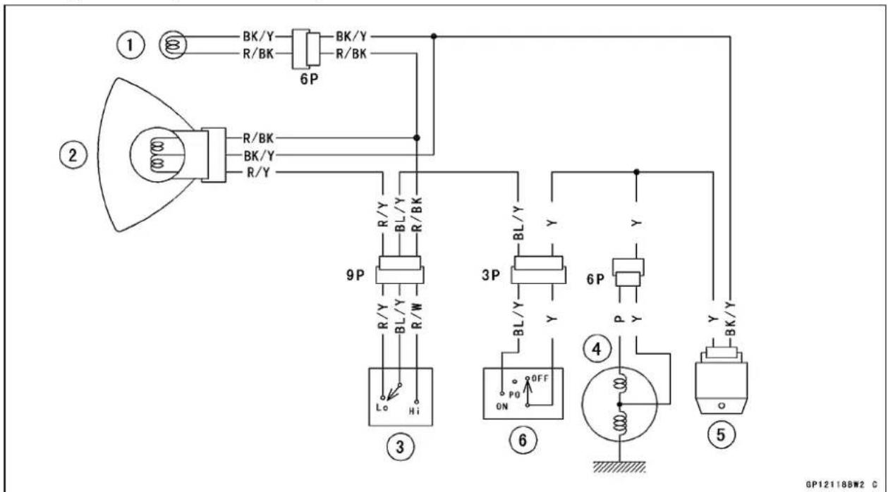
- Highbeamindicatorlight
2.Headlight -
Dimmerswitch
-
Alternator
- Regulator/rectifier
6.Headlightswitch
HeadlightCircuit(BN125-A3\~A5)
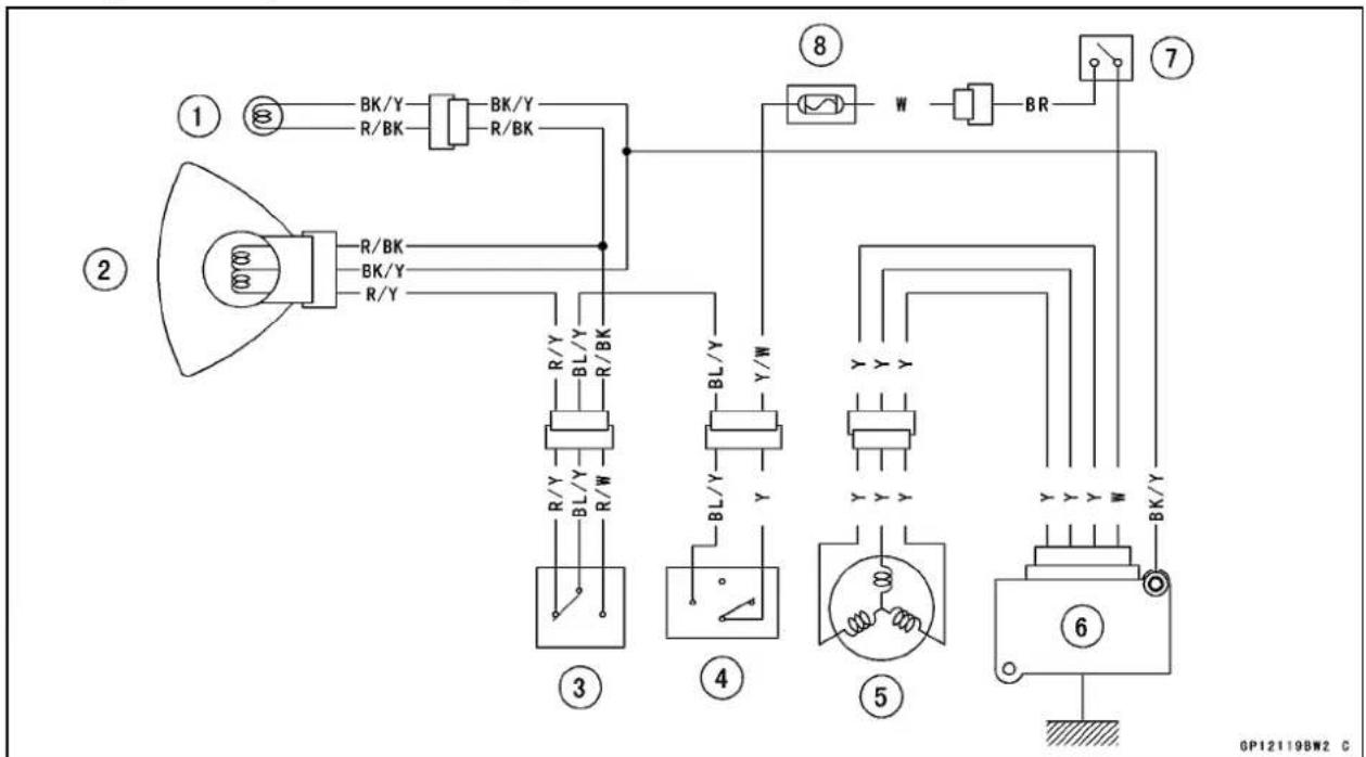
- Highbeamindicatorlight
2.Headlight -
Dimmerswitch
4.Headlightswitch -
Alternator
- Regulator/rectifier
- Ignitionswitch
8.Headlightfuse15A
LightingSystem
HeadlightCircuit(BN125-A6\~)

- Highbeamindicatorlight
2.Headlight
3.Dimmerswitch - Alternator
- Regulator/rectifier
- Ignitionswitch
7.Headlightfuse15A
Tail/BrakeLightBulbReplacement
- Removethetail/brakelightlens[A].
- Pushthebulb[A]inthesocket,turnitcounterclockwise [B],andpullitout.

natural_image
Close-up of a mechanical component with mesh grille and labeled point A (no readable text or symbols)
LightingSystem
- Withthefrontpin[A]down,insertthenewbulbbyaligning thefrontpinwiththegroove[B]inthewallsofthesocket.
- Pushthebulbin, turnitclockwise, andreplaceit. It should lockinposition.
- Tightenthelensscrews.Becarefulnottovertighten them.
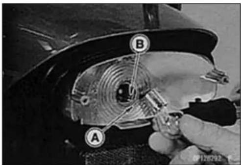
TurnSignalRelayInspection
- Removetherightsidecover(seeFramechapter).
- Connectone12Vbatteryandturnsignallightsasindicatedinthefigure,andcounthowmanytimesthelights flashforoneminute.
TurnSignalRelay[A]
TurnSignalLights[B]
12VBattery[C]
★ Ifthelightsdonotflashasspecified, replacetheturnsignalrelay.

TestingTurnSignalRelay
| Load | Flashingtimes (c/m*) | |
| TheNumberofTurn SignalLights | Wattage(W) | |
| 1** | 23or21 | Lightstayson or 140~250 |
| 242or4675~95 | ||
*:Cycle(s)perminute
**:Correspondto"onelightburnedout"

TurnSignalLightCircuit(BN125-A1/A2)

flowchart
graph TD
    A["1 ⑧ GY G"] --> B["6P"]
    B --> C["GY G"]
    C --> D["2 P R/W"]
    D --> E["BR"]
    E --> F["3 S"]
    F --> G["6 GY"]
    G --> H["8 BK/Y"]
    H --> I["9 P"]
    I --> J["8 L"]
    J --> K["+"]
    K --> L["10 BK/Y"]
    L --> M["11 W"]
    M --> N["12 + -"]
    N --> O["11"]
    style A fill:#f9f,stroke:#333
    style B fill:#ccf,stroke:#333
    style C fill:#cfc,stroke:#333
    style D fill:#fcc,stroke:#333
    style E fill:#cff,stroke:#333
    style F fill:#ffc,stroke:#333
    style G fill:#fcf,stroke:#333
    style H fill:#cff,stroke:#333
    style I fill:#cfc,stroke:#333
    style J fill:#cfc,stroke:#333
    style K fill:#cfc,stroke:#333
    style L fill:#cfc,stroke:#333
    style M fill:#cfc,stroke:#333
    style N fill:#cfc,stroke:#333
    style O fill:#cfc,stroke:#333
- Turnsignalindicatorlight
- Turnsignalrelay
- Ignition fuse 10A
- Frontrightturnsignallight
5.Frontleftturnsignallight - Rearrightturnsignallight
- Rearleftturnsignallight
- Turnsignalswitch
- Ignitionswitch
- Starterrelay
11.Mainfuse15A
12.Battery
GP12121BW3 C
LightingSystem
TurnSignalLightCircuit(BN125-A3\~A5)

flowchart
graph TD
    A["①"] --> B["②"]
    B --> C["③"]
    C --> D["④"]
    D --> E["⑤"]
    E --> F["⑥"]
    F --> G["⑦"]
    G --> H["⑧"]

    subgraph Terminal 1
        I["GY G"] --> J["6P"]
        K["GY G"] --> L["6P"]
    end

    subgraph Terminal 2
        M["BL/W"] --> N["2P"]
        O["BR"] --> P["BR"]
    end

    subgraph Terminal 3
        Q["BL/W"] --> R["BR"]
    end

    subgraph Terminal 4
        S["G BK/Y"] --> T["GY BK/Y"]
    end

    subgraph Terminal 5
        U["G BK/Y"] --> V["G BK/Y"]
    end

    subgraph Terminal 6
        W["GY BK/Y"] --> X["G BK/Y"]
    end

    subgraph Terminal 7
        Y["G BK/Y"] --> Z["G BK/Y"]
    end

    subgraph Terminal 8
        AA["GY BL/W"] --> AB["9P"]
        AC["GY BL/W"] --> AD["9P"]
        AE["GY BL/W"] --> AF["9P"]
        AG["GY BL/W"] --> AH["9P"]
        AI["GY BL/W"] --> AJ["9P"]
        AK["GY BL/W"] --> AL["9P"]
        AM["GY BL/W"] --> AN["9P"]
        AO["GY BL/W"] --> AP["9P"]
        AQ["GY BL/W"] --> AR["9P"]
        AS["GY BL/W"] --> AT["9P"]
        AU["GY BL/W"] --> AV["9P"]
        AW["GY BL/W"] --> AX["9P"]
        AY["GY BL/W"] --> AZ["9P"]
        BA["GY BL/W"] --> BB["9P"]
        BC["GY BL/W"] --> BD["9P"]
        BE["GY BL/W"] --> BF["9P"]
        BG["GY BL/W"] --> BH["9P"]
        BI["GY BL/W"] --> BJ["9P"]
        BK["GY BL/W"] --> BL["9P"]
        BM["GY BL/W"] --> BN["9P"]
        BO["GY BL/W"] --> BP["9P"]
        BQ["GY BL/W"] --> BR["9P"]
        BS["GY BL/W"] --> BT["9P"]
        BU["GY BL/W"] --> BV["9P"]
        BW["GY BL/W"] --> BX["9P"]
        BY["GY BL/W"] --> BZ["9P"]
        CA["GY BL/W"] --> CB["9P"]
        CC["GY BL/W"] --> CD["9P"]
        DD["GY BL/W"] --> DJ["9P"]
        DK["GY BL/W"] --> DL["9P"]
        DV["GY BL/W"] --> DW["9P"]
        DX["GY BL/W"] --> DXB["9P"]
        DXB --> DXC["9P"]
        DXC --> DXD["9P"]
        DXD --> DXE["9P"]
        DXE --> DXF["9P"]
        DXF --> DXG["9P"]
    end

    subgraph Terminals
    H
    I
    J
    K
    L
    M
    N
    O
    P
    Q
    R
    S
    T
    U
    V
    W
    X
    Y
    Z
    AA
    AB
    AC
    AD
    AE
    AF
    AG
    AH
    AI
    AJ
    AK
    AL
    AM
    AN
    AO
    AP
    AQ
    AR
    AS
    AT
    AU
    AV
    AW
    AX
    AY
    AZ
    BA
    BB
    BC
    BD
    BE
    BF
    BG
    BH
    BI
    BJ
    BK
    AL
    AM
    AN
    AO
    AP
    AQ
    AR
    AS
    AT
    AU
    AV
    AW
    AX
    AY
    AZ
    BA
    BB
    BC
    AD
    AE
    AF
    AG
    AH
    AI
    AJ
    AK
    AL
    AM
    AN
    AO
    AP
    AQ
    AR
    AS
    AT
    AU
    AV
    AW
   AX
   AB
   AC
    AD
    AE
    AF
    AG
    AH
    AI
    AJ
    AK
    AL
    AM
    AN
    AO
    AP
    AQ
    AR
    AS
    AT
    AU
    AV
    AW
   AX
   AB
   AC
   AD
    AE
    AF
    AG
    AH
   AI
    AJ
    AK
   AL
    AM
    AN
    AO
- Turnsignalindicatorlight
- Turnsignalrelay
- Ignitionfuse15A
4.Frontrightturnsignallight
5.Frontleftturnsignallight - Rearrightturnsignallight
- Rearleftturnsignallight
- Turnsignalswitch
- Ignitionswitch
- Starterrelay
11.Mainfuse30A
12.Battery
TurnSignalLightCircuit(BN125-A6\~)

flowchart
graph TD
    A["IGNITION"] --> B["BATTERY"]
    B --> C["BR W"]
    C --> D["BR W"]
    D --> E["BR W"]
    E --> F["BL/W"]
    F --> G["BL/W"]
    G --> H["BR W"]
    H --> I["3"]
    I --> J["BR"]
    J --> K["BR"]
    K --> L["BL/W"]
    L --> M["BL/W"]
    M --> N["2"]
    N --> O["BL/W"]
    O --> P["BR W"]
    P --> Q["BR W"]
    Q --> R["1"]
    R --> S["GY G"]
    S --> T["GY G"]
    T --> U["GY"]
    U --> V["GY"]
    V --> W["GY"]
    W --> X["GY"]
    X --> Y["GY"]
    Y --> Z["GY"]
    Z --> AA["GY"]
    AA --> AB["GY"]
    AB --> AC["GY"]
    AC --> AD["GY"]
    AD --> AE["GY"]
    AE --> AF["GY"]
    AF --> AG["GY"]
    AG --> AH["GY"]
    AH --> AI["GY"]
    AI --> AJ["GY"]
    AJ --> AK["GY"]
    AK --> AL["GY"]
    AL --> AM["GY"]
    AM --> AN["GY"]
    AN --> AO["GY"]
    AO --> AP["GY"]
    AP --> AQ["GY"]
    AQ --> AR["GY"]
    AR --> AS["GY"]
    AS --> AT["GY"]
    AT --> AU["GY"]
    AU --> AV["GY"]
    AV --> AW["GY"]
    AW --> AX["GY"]
    AX --> AY["GY"]
    AY --> AZ["GY"]
    AZ --> BA["GY"]
    BA --> BB["GY"]
    BB --> BC["GY"]
    BC --> BD["GY"]
    BD --> BE["GY"]
    BE --> BF["GY"]
    BF --> BG["GY"]
    BG --> BH["GY"]
    BH --> BI["GY"]
    BI --> BJ["GY"]
    BJ --> BK["GY"]
    BK --> BL["GY"]
    BL --> BM["GY"]
    BM --> BN["GY"]
    BN --> BO["GY"]
    BO --> BP["GY"]
    BP --> BQ["GY"]
    BQ --> BR["GY"]
    BR --> BS["GY"]
    BS --> BT["GY"]
    BT --> BU["GY"]
    BU --> BV["GY"]
    BV --> BW["GY"]
    BW --> BX["GY"]
    BX --> BY["GY"]
    BY --> BZ["GY"]
    BZ --> CA["GY"]
    CA --> CB["GY"]
    CB --> CC["GY"]
    CC --> CD["GY"]
    CD --> CE["GY"]
-
Turnsignalindicatorlight
-
Turnsignalrelay
-
Ignition fuse 15A
4.Frontrightturnsignallight
5.Frontleftturnsignallight
-
Rearrightturnsignallight
-
Rearleftturnsignallight
-
Turnsignalswitch
-
Ignitionswitch
-
Starterrelay
11.Mainfuse30A
12.Battery
Meter, Gauge, IndicatorUnit
SpeedometerRemoval
- Removethespeedometercableupperend[A].
- Removethemeterunit[C]bytakingoffthemountingbolts [B].
CAUTION
Placethemetersothatthefaceisup.lfameteris leftupsidedownorsidewaysforanylengthoftime, itwillmalfunction.
SpeedometerDisassembly
- Remove:
Speedometer(seethischapter)
Screws[A]
Screw[B]andKnob[C]
- Toremovethewedge-basetypebulb[A], thenpullthe bulboutofthesocket.
CAUTION
Donotturnthebulb.Pullthebulbouttoprevent damagetothebulb.Donotusebulbratedforother thanvoltageorwattagespecifiedinthewiringdiagram.
IndicatorUnitRemoval/Installation
- Removethebolts[A]andindicatorunit[B]fromthefuel tank.
- Wheninstallingtheindicatorunit,tightenthefrontbolt first.
BulbReplacement
- Toremovethewedge-basetypebulb[A], pullthebulbout ofthesocket[B].
CAUTION
Donotturnthebulb.Pullthebulbouttoprevent damagetothebulb.Donotusebulbratedforother thanvoltageorwattagesspecifiedinthewiringdiagram.
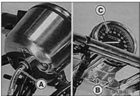
natural_image
Mechanical assembly diagram showing a cylindrical component with labeled parts A and B, and a dial indicator (no readable text or symbols)

natural_image
Close-up of hands assembling a mechanical component with a labeled part (A), no visible text or symbols beyond the label.
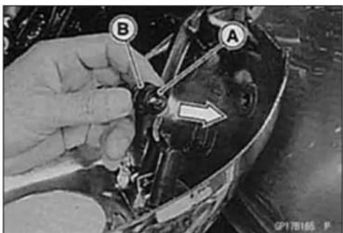
SwitchesandSensors
FrontBrakeLightSwitchInspection
- RefertotheFrontBrakeLightSwitchInspectioninthe PeriodicMaintenancechapter.
RearBrakeLightTimingInspection
- RefertotheRearBrakeLightTimingInspectioninthe PeriodicMaintenancechapter.
RearBrakeLightTimingAdjustment
- RefertotheRearBrakeLightTimingAdjustmentinthe PeriodicMaintenancechapter.
SwitchInspection
- Usingthehandtester, checktoseethatonlytheconnectionsshowninthetablehavecontinuity(about0Ω).
○Forthehandlebarswitchesandtheignitionswitch, refer tothetablesintheWiringDiagram.
★ Iftheswitchhasanopenorshort,repairitorreplaceit withanewone.
SpecialTool-HandTester:57001-1394
| Rear Brake Light Switch Connections | ||
| Color | BR | BL/W |
| When brake pedal is pushed down | ○ | ○ |
| When brake pedal is released | ||
| Sidestand Switch Connections | ||
| Color | BK | G |
| When sidestand is down | ||
| When sidestand is up | ○— | ○ |
| Neutral Switch Connections | ||
| Color | SW.Terminal | Ground |
| When transmission is in neutral | ○— | ○ |
| When transmission is not in neutral | ||
Fuse
MainFuse15ARemoval
- Removetherightsidecover(seeFramechapter).
- Disconnectthestarterrelayconnector.
- Pulloutthemainfuse[B]fromthestarterrelay[A]with needlenosepliers.

MainFuse15AInspection
- Removethefuse(seeFuseRemoval).
- Inspectthefuseelement.
★ Ifitisblownout, replacethefuse. Before replacing a blownfuse, always check the amperage in the affected circuit. If the amperage is equal to greater than the fuserating, check the wiring and related components for ashort circuit.
Housing[A]
FuseElement[B]
Terminals[C]
BlownElement[D]

CAUTION
Whenreplacingafuse,besurethenewfuse matchesthespecifiedfuseratingforthatcircuit. Installationofafusewithahigherratingmaycause damagetowiringandcomponents.
Fuse10ARemoval
- Removetherightsidecover(seeFramechapter).
- Openthefusecase[A]andremovethefuses[B].
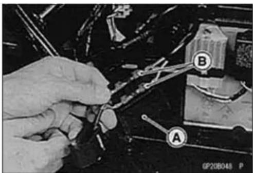
Fuse10AInstallation
★ Ifafusefailsduringoperation,inspecttheelectricalsystemtodeterminethecause,andthenreplaceitwitha newfuseorproperamperage.
CAUTION
Thefusecasehas10Afusesonly.Donotusethe fuseotherthan10Afuse.
Fuse
Fuse10AInspection
- Inspectthefuseelement.
★Ifitisblownout, replacethefuse.
FuseElement[A]
BlownElement[B]

Appendix
TableofContents
Cable, Wire, and Hose Routing 16-2
Troubleshooting Guide 16-32
BN125-A1\~


Cable, Wire, and HoseRouting
- CrankshaftSensor
2.OilPipe - Clamp
- Runthealternatorleadundertheoilpipe.
- AlternatorLead
- Runtheneutralswitchleadsothatitshallnotoutofguiderib.
- GuideRib
- NeutralSwitch
- TurnSignalRelay
- EngineGroundLead
11.Holder
12.CarburetorDrainHose
13.BatteryVentHose
BN125-A1\~
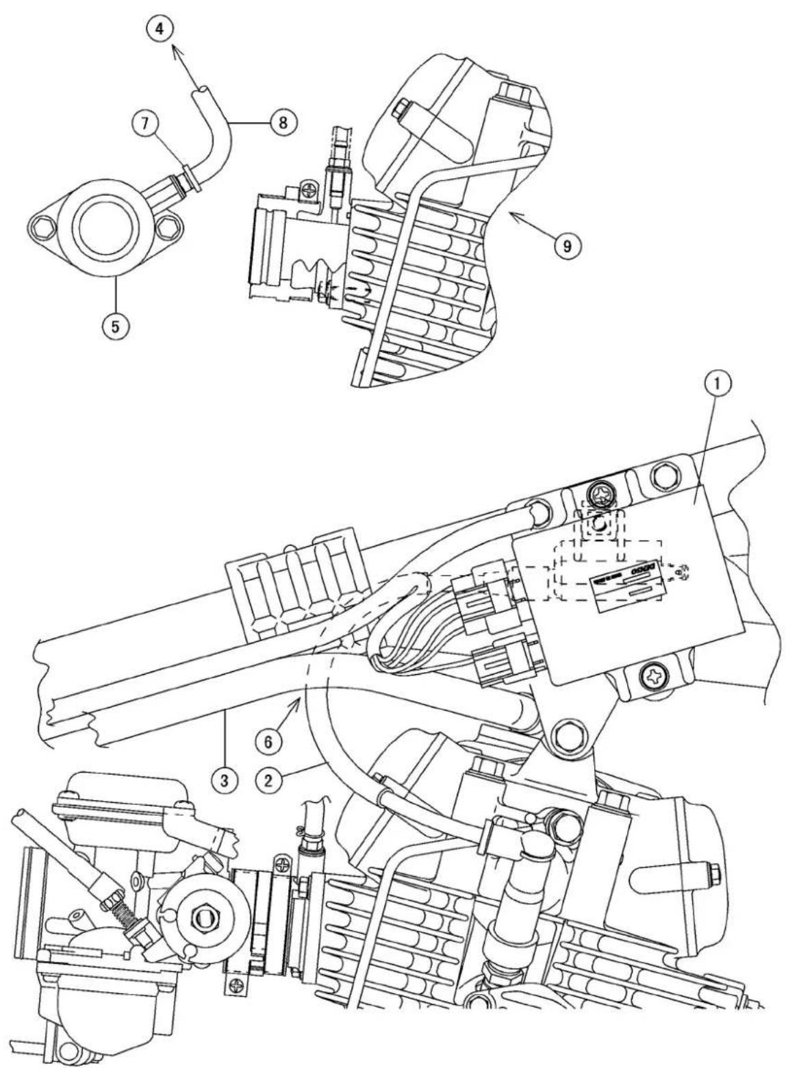
Cable, Wire, and HoseRouting
1.CDIUnit
2. Ignition Coil Lead
3. EngineBreatherHose
4. ToFuelTap
5. Insulator
6. Runtheignitioncoilleadundertheenginebreatherhose.
7. Clamp
8. Install the hose as shown.
9. Other than AT, DE, SG, CH Models
AT:Austria
CH:Switzerland
DE:Germany
SG:Singapore
CleanAirSystem

Cable, Wire, and HoseRouting
- VacuumHose
- Three-way Joint
- ToFuelTap
4.AirHose
5.AirPipe - EngineBreatherHose
- AirCleanerDuct
8.AirCleanerHousing - VacuumSwitch
- Carburetor
11.AirSuctionValve - Insulator
- Run the vacuum hose onto the left side of the duct (7), and then behind the hose (6) and carburetor (10).
- Themarkfacesupward.
15.PositioningMark - ArrowMark(facestowardthevacuumhose)
- Clamp
Note: The position mark(15), arrowmark(16) and vacuum hose(1) shall be inline as shown.
BN125-A1\~A4

Cable, Wire, and HoseRouting
- IgnitionSwitch
- Runtheignitionswitchleadtotheright.
3.SidestandSwitchLead - Runthesidestandswitchleadtotheright.
5.BodyGround
6.IgnitionCoil - Alternator Lead Connector
8.SidestandSwitch - Clamp
10.Band
BN125-A5\~
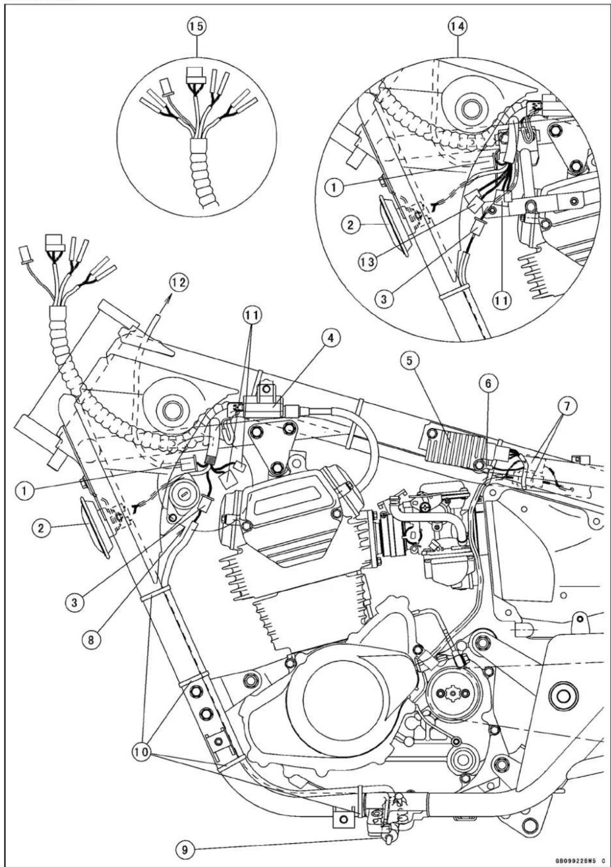
Cable, Wire, and HoseRouting
- IndicatorLightConnector(Moveittotherightsideafterconnected.)
2.Horn - Sidestandswitchconnector
- Ignitioncoil
- Regulator/Rectifier
6.GroundLead - AlternatorLead
- Puttheconnectorsintothegussetafterconnectingthem.
9.SidestandSwitch
10.Band
11.LeftHandlebarSwitchConnector - Connectitinthefueltankcover.
13.RightHandlebarSwitchConnector - California Model
- EuropeModel
BN125-A1\~
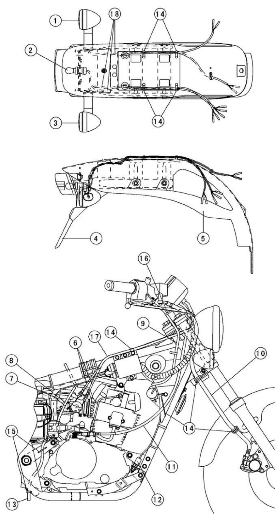
Cable, Wire, and HoseRouting
- RearLeftTurnSignalLight
- Tail/BrakeLight
- RearRightTurnSignalLight
4.RearFenderRear - RearFenderFront
6.ThrottleCables - CarburetorAirVentHose
- EngineBreatherHose
9.RightHandlebarSwitch
10.BrakeHose
11.ClutchCable
12.RearBrakeLightSwitch
13.BatteryVentHose
14.Clamp
15.Holder
16.Band - Runthethrottlecablesinsidetherighthandlebarswitch.
18.Runtheleft/rightrearturnsignallight,tail/brakelightleadsbetweentheststayandtherearfender.
BN125-A1\~


Cable, Wire, and HoseRouting
- ThrottleCables
- ClutchCable
- Speedometer Cable
4.LeftHandlebarSwitchHarness
5.RightHandlebarSwitchHarness
6.SidestandSwitch
7.Holder
8.Band - Clamp
10.BN125-A3\~
BN125-A1\~A2

Cable, Wire, and HoseRouting
- Tail/BrakeLightConnector
- RearLeftTurnSignalLightConnector
- White Tape
- Ignition Coil Connector
5.BodyGround
6.FrontLeftTurnSignalLightConnector - FrontRightTurnSignalLightConnector
- Joinconnectorsintheheadlightunit.
- SpeedometerLightConnector
10.HeadlightConnector
11.RearRightTurnSignalLightConnector
12.InterlockDiodes
13.StarterCircuitRelayConnector
14.StarterRelayConnector
15.Regulator/RectifierConnector
16.FuseBoxConnector - TurnSignalRelayConnector
18.BatteryNegativeLead - AlternatorConnector
20.CDIUnit
21.LeftHandlebarSwitchConnector
22.RightHandlebarSwitchConnector
23.RearBrakeLightSwitchConnector
24.IgnitionSwitchConnector
25.IndicatorLightConnector
26.SidestandLightConnector
27.HornConnector
28.BatteryPositiveLead
29.CDIUnitConnector
30.Battery
31.RightHandlebarSwitchLeadConnector
32.CityLightConnector(EuropeModel)
33.Band
34.Clamp
35.StarterLead
36.RearBrakeLightSwitch
37.TurnSignalRelay
BN125-A3\~A4

Cable, Wire, and HoseRouting
- RearLeftTurnSignalLightConnector
- Tail/BrakeLightConnector
3.Band
4.GroundLead - Ignition Coil Lead
6.Regulator/RectifierConnector
7.CDIUnitConnector
8.LeftHandlebarSwitchConnector
9.HornConnector
10.IndicatorLightConnector
11.SidestandSwitchConnector
12.HeadlightConnector
13.FrontRightTurnSignalLightConnector
14.FrontLeftTurnSignalLightConnector
15.RearRightTurnSignalLightConnector
16.DiodeConnector
17.StarterCircuitRelayConnector
18.StarterRelayConnector
19.FuseBoxConnector
20.AlternatorConnector
21.IgnitionSwitchConnector(CaliforniaModel)
22.BatteryNegativeLead
23.TurnSignalRelayConnector
24.RightHandlebarSwitchConnector - IgnitionSwitchConnector(OtherThanCaliforniaModel)
26.RearBrakeSwitchConnector
27.BatteryPositiveLead
28.Runthethrottlesensorleadtoleftside.
29.Turnsignalrelay
30.Runtheindicatorlightleadfromleftside.
31.StarterLead
32.SpeedometerConnector
33.CityLightConnector(EuropeModel)
34.Clamp
35.Putthemintothegussetafterconnected. - Connect them in the headlighthousing.
BN125-A5\~

Cable, Wire, and HoseRouting
- RearLeftTurnSignalLightConnector
- Tail/BrakeLightConnector
3.Band - White Tape
5.GroundLead
6.Regulator/RectifierConnector - Ignition Coil Lead
8.LeftHandlebarSwitchConnector
9.HornConnector
10.IndicatorLightConnector
11.SidestandSwitchConnector
12.FrontLeftTurnSignalLightConnector
13.FrontRightTurnSignalLightConnector
14.HeadlightConnector
15.SpeedometerConnector
16.CityLightConnector(EuropeModel) - IgnitionSwitchConnector
18.RearBrakeSwitchConnector
19.RightHandlebarSwitchConnector
20.CDIUnitConnector - AlternatorConnector
22.BatteryNegativeLeadConnector
23.TurnSignalRelayConnector
24.FuseBoxConnector
25.StarterRelayConnector
26.StarterCircuitRelayConnector
27.DiodeConnector
28.RearRightTurnSignalLightConnector - Tiewiththestaybythebandafterconnected.
30.CaliforniaModel
BN125-A5\~

Cable, Wire, and HoseRouting
- DiodeConnector
2.FuseBoxConnector
3.BatteryPositiveLead - Clamp
- TurnSignalRelay
- Alternator Connector
7.BatteryNegativeLead
8.Band
9.CDIUnitConnector
10.IgnitionCoilLead
11.Runtheindicatorlightleadfromleftside.
12. Connect them in the headlighthousing.
13.CityLightConnector(EuropeModel)
- IgnitionSwitchConnector
15.Putthemintothegussetafterconnected.
16.RearBrakeSwitchConnector
17.RightHandlebarSwitchConnector
18.StarterLead
19.Battery
20.StarterCircuitRelay
21.CaliforniaModel
Evaporative Emission Control System (BN125-A5 \~ : California Model)
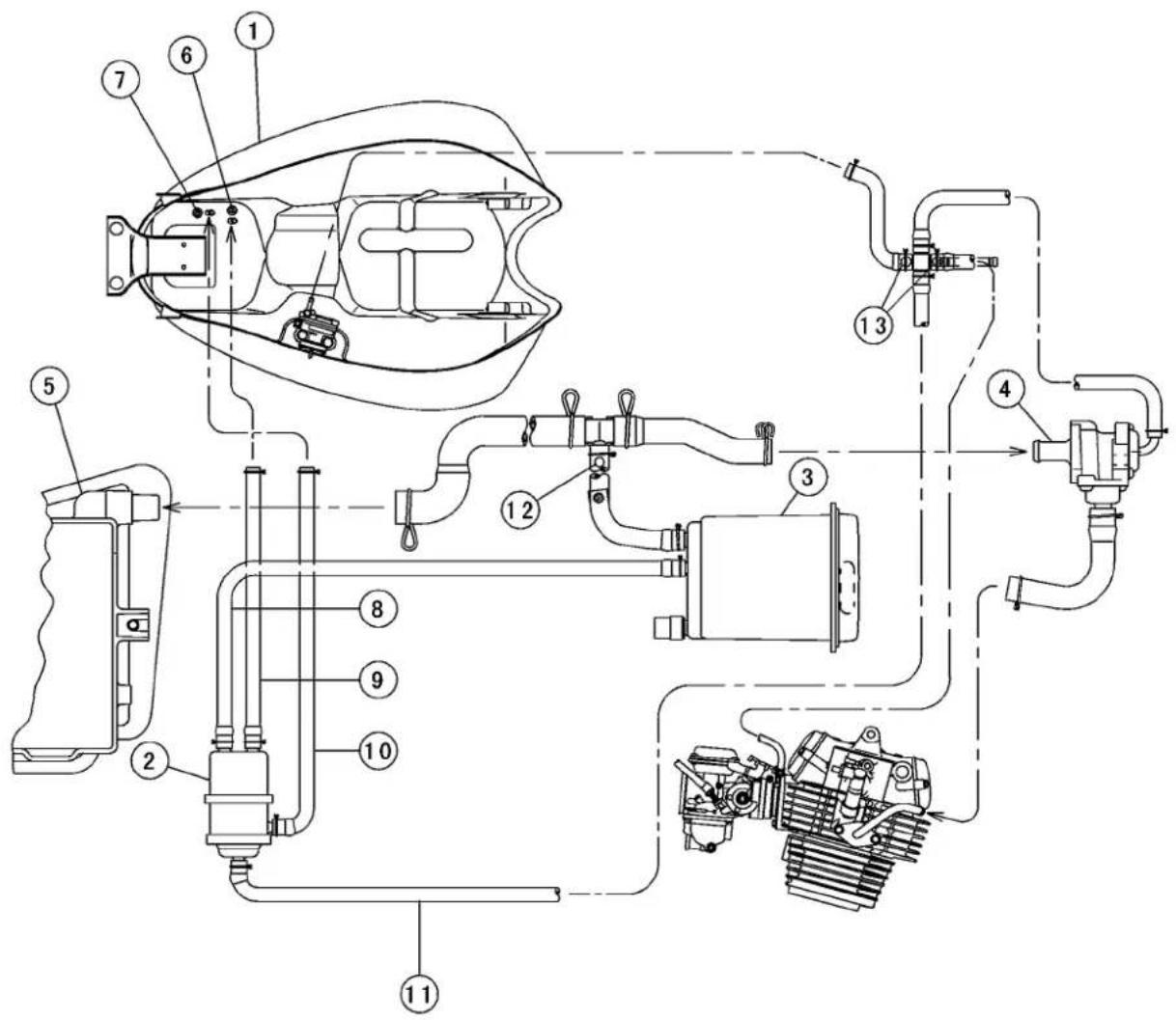
Cable, Wire, and HoseRouting
1.FuelTank
2.Separator
3.Canister
4. VacuumSwitchValve
5.AirCleanerHousing
6.Label(Blue)
7.Label(Red)
8.Hose(withbluestripe)
9.Hose(withbluestripe)
10.Hose(withredstripe)
11.Hose(withwhitestripe)
12. WhitePaintMark
13. WhitePaintMark
Evaporative Emission Control System (BN125-A5 \~ : California Model)

Cable, Wire, and HoseRouting
- VacuumSwitchValve
- Gotothefueltap
- CarburetorHolder
4.Separator
Evaporative Emission Control System (BN125-A5 \~ : California Model)
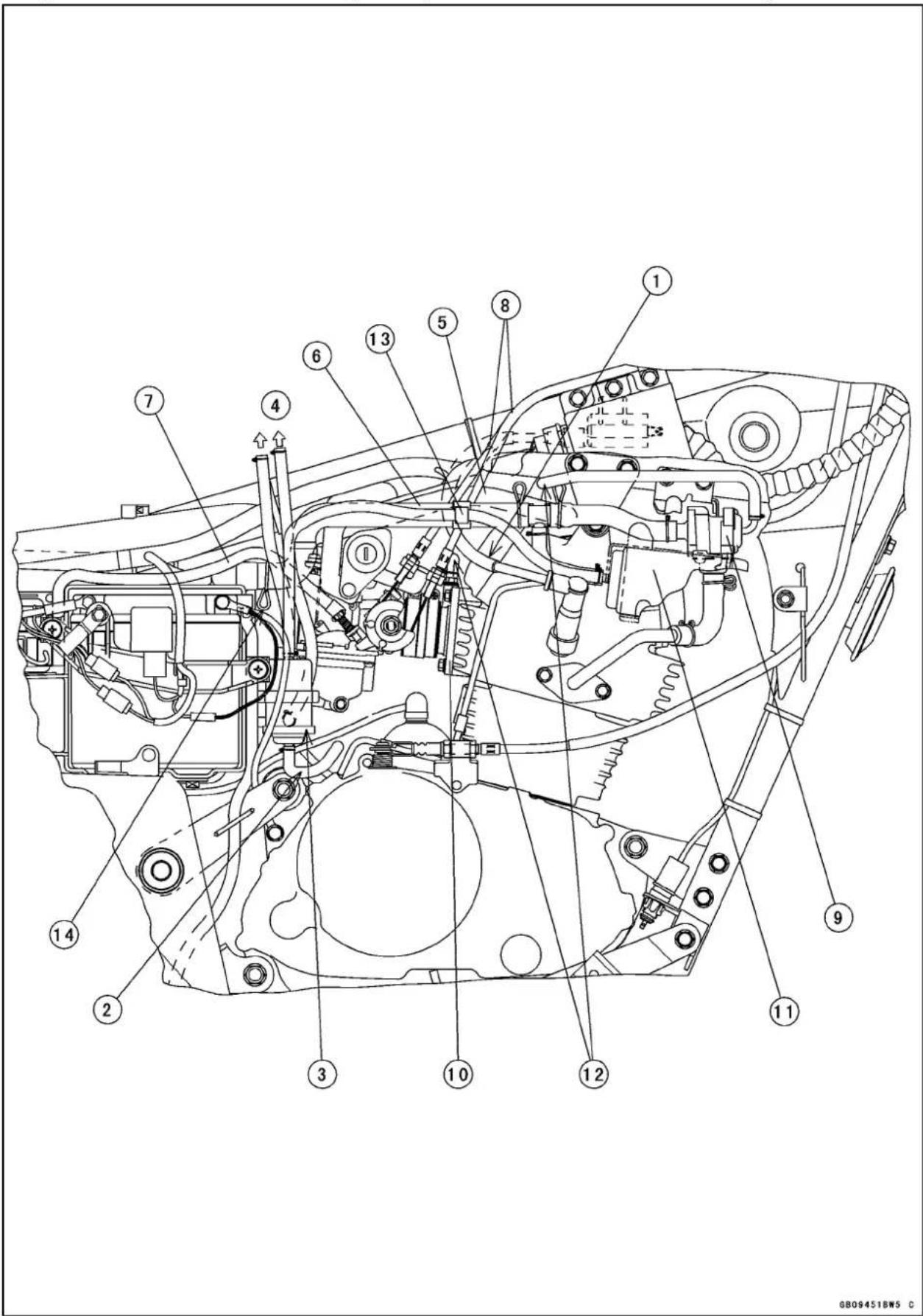
Cable, Wire, and HoseRouting
- Runtheignitioncoilprimaryleadunderthethrottlecables, secondaryairhoseandbreather hose.
2.GoToLeftSide
3.Separator
4.GoToTheFuelTank
5.BreatherHose - SecondaryAirHose
7.AirVentHose
8.ThrottleCables - VacuumSwitchValve
- CarburetorHolder
11.Canister
12.GoToLeftSide - Clamp
14.Knobofclipshallbeinstalleddownward.
Evaporative Emission Control System (BN125-A5 \~ : California Model)

Cable, Wire, and HoseRouting
1.MainHarness
2.BreatherHose
3. SecondaryAirHose
4. AirVentHose
5. Gotothefueltank
6.Separator
7. Gotothecanister
8. Clamp
9.Front
TroubleshootingGuide
NOTE
○ Thisisnotanexhaustivelist, giving every possible cause foreach problem listed. It is meant simply as a rough guideto assist the troubleshooting for some of them more common difficulties.
EngineDoesn'tStart, Starting Difficulty:
Startermotornotrotating:
Starterlockoutswitchorneutralswitchtrouble Startermotortrouble Batteryvoltagelow Starterrelaynotcontactingoroperating Starterbuttonnotcontacting Wiringopenorshorted Ignitionswitchtrouble Enginestopswitchtrouble Fuseblown
Startermotorrotatingbutenginedoesn't turnover:
Startermotorclutchtrouble Torquelimitertrouble
Nofuelintank Fueltankairventobstructed Fueltapvacuumhoseclogged Fueltapclogged Fuellineclogged Floatvalveclogged
Engineflooded:
Fuellevelincarburetorfloatbowltoohigh Floatvalvewornorstuckopen Startingtechniquefaulty(Whenflooded, cranktheenginewiththethrottlefully openedtoallowmore air toreach the engine.)
Nospark;sparkweak:
Batteryvoltagelow Ignitionswitchnoton Enginestopswitchturnedoff Clutch lever not pulled in or gear not in neutral Sparkplugdirty, broken, orgapmaladjusted
Sparkplugcaporhightensionwiringtrouble Sparkplugcapshortedornotingoodcontact Sparkplugincorrect CDlunittrouble Neutral, starterlockoutswitch, or sidesta switchtrouble Crankshaftsensortrouble Ignitioncoiltrouble Ignitionorenginestopswitchshorted Wiringshortedoropen Fuseblown
Fuel/airmixtureincorrect:
Pilot screw and/or idle adjusting screw mal-adjusted Pilotjet, orairpassage clogged Air cleaner clogged, poorly sealed, or missing Starterjet clogged
CompressionLow:
Sparkplugloose Cylinder head not sufficiently tightened down Novalveclearance Cylinder, pistonworn Piston ringbad (worn, weak, broken, or sticking) Pistonring/grooveclearanceexcessive Cylinderheadgasketdamaged Cylinderheadwarped Valve spring broken or weak Valve not seating properly (valve bent, worn, orcarbonaccumulationonthe seatingsurface)
PoorRunningatLowSpeed:
Sparkweak:
Batteryvoltagelow Sparkplugdirty, broken, orgapmaladjusted Sparkplugcaporhightensionwiringtrouble Sparkplugcapshortedornotingoodcontact Sparkplugincorrect CDlunittrouble Crankshaftsensortrouble Ignitioncoiltrouble
Fuel/airmixtureincorrect:
Pilotscrewmaladjusted Pilotjet, orairpassageclogged Needlejetbleedholes orneedlejetclogged Pilotpassageclogged Air cleaner clogged, poorly sealed, or missing Starterplungerstuckopen
TroubleshootingGuide
Fuellevelincarburetorfloatbowltoohigh ortoolow
Fueltankairventobstructed
Carburetorholderloose
Aircleanerductloose
Fueltapclogged
AircleanerO-ringdamaged
Compressionlow:
Sparkplugloose
Cylinderheadnotsufficientlytightened down
Novalveclearance
Cylinder, pistonworn
Pistonringbad(worn,weak,broken,or sticking)
Pistonring/grooveclearanceexcessive
Cylinderheadwarped
Cylinderheadgasketdamaged
Valvespringbrokenorweak
Valvenotseatingproperly(valvebent, worn,orcarbonaccumulationonthe seatingsurface)
Other:
CDlunittrouble
Carburetorvacuumpistondoesn'tslide smoothly
Carburetorvacuumpistondiaphragmdamage
Engineoilviscositytoohigh
Drivetraintrouble
Brakedragging
Overheating
Clutchslipping
Airsuctionvalvetrouble(AT,DE,SG,CH)
Vacuumswitchvalvetrouble(AT,DE,SG,CH)
Castingenrichertrouble
PoorRunningorNoPoweratHigh Speed:
Firingincorrect:
Spark plug dirty, broken, or gap maladjusted
Sparkplugcaporhightensionwiringtrouble
Sparkplugcapshortedornotingoodcontact
Sparkplugincorrect
CDlunittrouble
Crankshaftsensortrouble
Ignitioncoiltrouble
Fuel/airmixtureincorrect:
Starterplungerstuckopen
Mainjetcloggedorwrongsize
Jetneedleorneedlejetworn
Airjetclogged
Fuellevelincarburetorfloatbowltoohigh ortoolow
Needle jet bleed holes or needle jet clogged
Aircleanerclogged,poorlysealed,ormissing
Aircleanerductloose
Fueltocarburetorinsufficient
Waterorforeignmatterinfuel
Carburetorholderloose
Fueltankairventobstructed
Fueltapclogged
Fuellineclogged
Compressionlow:
Sparkplugloose
Cylinderheadnotsufficientlytightened down
Novalveclearance
Cylinder, pistonworn
Pistonringbad(worn,weak,broken, or sticking)
Pistonring/grooveclearanceexcessive
Cylinderheadgasketdamaged
Cylinderheadwarped
Valve spring broken or weak
Valvenotseatingproperly (valvebent, worn, orcarbonaccumulation on the seatingsurface.)
Knocking:
Carbonbuiltupincombustionchamber
Fuelpoorqualityorincorrect
Sparkplugincorrect
CDlunit
Miscellaneous:
Throttlevalvewon'tfullyopen
Carburetorvacuumpistondoesn't slide smoothly
Carburetorvacuumpistondiaphragmdamaged
Brakedragging
Clutchslipping
Overheating
Engineoilleveltoohigh
Engineoilviscositytoohigh
Drivetraintrouble
Airsuctionvalvetrouble(AT,DE,SG,CH)
Vacuumswitchvalvetrouble(AT,DE,SG,CH)
Balancermechanismmalfunctioning
Coastingenrichertrouble
Overheating:
Firingincorrect:
Spark plug dirty, broken, or gap maladjusted
Sparkplugincorrect
CDlunittrouble
TroubleshootingGuide
Fuel/airmixtureincorrect:
Mainjetcloggedorwrongsize
Fuellevelincarburetorfloatbowltoolow
Carburetorholderloose
Aircleanerductloose
Aircleanerpoorlysealed,ormissing
AircleanerO-ringdamaged
Aircleanerclogged
Compressionhigh:
Carbonbuiltupincombustionchamber
Engineloadfaulty:
Clutchslipping
Engineoilleveltoohigh
Engineoilviscositytoohigh
Drivetraintrouble
Brakedragging
Lubricationinadequate:
Engineoilleveltoolow
Engineoilpoorqualityorincorrect
ClutchOperationFaulty:
Clutchslipping:
Noclutchleverplay
Clutchinnercablecatching
Clutchcableunadjusted
Frictionplatewornorwarped
Steelplatewornorwarped
Clutchspringbrokenorweak
Clutchreleasemechanismtrouble
Clutchhuborhousingunevenlyworn
Clutchnotdisengagingproperly:
Clutchleverplayexcessive
Clutchplatewarpedortoorough
Clutchspringcompressionuneven
Engineoildeteriorated
Engineoilviscositytoohigh
Engineoilleveltoohigh
Clutchhousingfrozenondriveshaft
Clutchreleasemechanismtrouble
Clutchhubnutloose
Clutchhubsplinedamaged
GearShiftingFaulty:
Doesn'tgointogearshiftpedaldoesn't return:
Clutchnotdisengaging
Shiftforkbentorseized
Gearstuckontheshaft
Gearsetleverbinding
Shiftreturnspringweakorbroken
Shiftreturnspringpinloose
Shiftmechanismarmspringbroken
Shiftmechanismarmbroken
Shiftpawlbroken
Jumpsoutofgear:
Shiftforkearworn,bent
Geargrooveworn
Geardogsand/ordogholesworn
Shiftdrumgrooveworn
Gearsetleverspringweakorbroken
Shiftforkguidepinworn
Driveshaft, outputshaft, and/orgear splinesworn
Overshifts:
Gearsetleverspringweakorbroken
Shiftmechanismarmspringbroken
AbnormalEngineNoise:
Knocking:
CDlunittrouble
Carbonbuiltupincombustionchamber
Fuelpoorqualityorincorrect
Sparkplugincorrect
Overheating
Pistonslap:
Cylinder/pistonclearanceexcessive
Cylinder, pistonworn
Connectingrodbent
Pistonpin, pistonpinholeworn
Valvenoise:
Valveclearanceincorrect
Valvespringbrokenorweak
Camshaftbearingworn
Rockerarmworn
Rockershaftworn
Othernoise:
Connectingrodsmallendclearanceexcessive
Connectingrodbigendclearanceexcessive
Pistonringworn,broken,orstuck
Pistonseizure,damage
Cylinderheadgasketleaking
Exhaustpipeleakingatcylinderheadconnection
Crankshaftrunoutexcessive
Enginemountsloose
Crankshaftbearingsworn
Primarygearwornorchipped
Camshaftchaintensionertrouble
Camshaftchain,sprocket,guideworn
Airsuctionvalvedamaged(AT,DE,SG,CH)
Vacuum switch valve damaged (AT, DE, SG, CH)
Balancergearwornorchipped
Balancershaftgearpositionmaladjusted
Balancerbearingworn
Alternatorrotorloose
TroubleshootingGuide
AbnormalDriveTrainNoise:
Clutchnoise:
Clutchrubberdamperweakordamaged
Clutchhousingfinger/frictionplatetang clearanceexcessive
Clutchhousinggearworn
Metalchipsjammedinclutchhousinggear
Transmissionnoise:
Bearingsworn
Transmissiongearswornorchipped
Metalchipsjammedingearteeth
Engineoilinsufficient
Drivechainnoise:
Drivechainadjustedimproperly
Drivechainworn
Rearand/orenginesprocketworn
Chainlubricationinsufficient
Rearwheelmisaligned(Rightwheelbearingsarenotbottomedout)
AbnormalFrameNoise:
Frontforknoise:
Oilinsufficientortoothin
Springweakorbroken
Rearshockabsorbernoise:
Shockabsorberdamaged
Springweakorbroken
Discbrakenoise:
Padinstalledincorrectly
Padsurfaceglazed
Discwarped
Calipertrouble
Mastercylinderdamaged
Drumbrakenoise:
Brakeliningsoverwornorwornunevenly
Drumwornunevenlyorscored
Brakespringsweakorbroken
Foreignmatterinhub
Brakenotproperlyadjusted
Othernoise:
Bracket, nut, bolt, etc. not properly mountedortightened
ExhaustSmokesExcessively:
Whitesmoke:
Pistonoilringworn
Cylinderworn
Valveoilsealdamaged
Valveguideworn
Engineoilleveltoohigh
Blacksmoke:
Aircleanerclogged
Mainjettoolargeorfallenoff
Starterplungerstuckopen
Fuellevelincarburetorfloatbowltoohigh
Brownsmoke:
Mainjettoosmall
Fuellevelincarburetorfloatbowltoolow
Aircleanerductloose
AircleanerO-ringdamaged
Aircleanerpoorlysealedormissing
Handling and/or Stability Unsatisfactory:
Handlebarhardtoturn:
Cableroutingincorrect
Hoseroutingincorrect
Wiringroutingincorrect
Steeringstemnuttootight
Steeringstembearingdamaged
Steeringstembearinglubricationinadequate
Steeringstembent
Tireairpressuretoolow
Handlebarshakesorexcessivelyvibrates:
Tireworn
Swingarmpivotbearingsworn
Handlebarnutloose
Rimwarped,ornotbalanced
Wheelbearingworn
Spokesloose
Steeringstemheadboltloose
Front, rearaxlerunoutexcessive
Handlebarpullstooneside:
Framebent
Wheelmisalignment(Rightwheelbearings arenotbottomedout)
Swingarmbentortwisted
Swingarmpivotshaftbent
Steeringmaladjusted
Frontforkbent
Rightandleftfrontforkoilleveluneven
Rightandleftshockabsorberadjustment uneven
Shockabsorptionunsatisfactory:
(Toohard)
Frontforkoilexcessive
Frontforkoilviscositytoohigh
Rearshockabsorberadjustmenttoohard
Tireairpressuretoohigh
Frontforkbent
(Toosoft)
Tireairpressuretoolow
Frontforkoilinsufficientand/orleaking
Frontforkoilviscositytoolow
Rearshockadjustmenttoosoft
Frontfork, rearshockabsorberspringweak
Rearshockabsorberoilleaking
BrakeDoesn'tHold:
Discbrake:
Airinthebrakeline
Padordiscworn
Brakefluidleakage
TroubleshootingGuide
Discwarped
Contaminatedpad
Brakefluiddeteriorated
Primaryorsecondarycupdamagedinmastercylinder
Brakemastercylinderscratchedinside
Drumbrake:
Brakemaladjusted
Brakeliningsordrumworn
Overheated
Waterinbrakedrum
Brakecam, camshaftworn
Oilonbrakelinings
BatteryTrouble:
Batterydischarged:
Batteryfaulty(e.g., platessulphated, shortedthroughsedimentation, electrolyteinsufficient)
Batteryleadsmakingpoorcontact
Loadexcessive(e.g.,bulbofexcessive wattage)
Ignitionswitchtrouble
Alternatortrouble
Wiringfaulty
Regulator/rectifiertrouble
Batteryovercharged:
Regulator/rectifiertrouble
Batteryfaulty
MODELAPPLICATION
| YearModel | BeginningFrameNo. | |
| 1998BN1 | 25-A1 | BN125A000001orJKABN125AAA000001 |
| 1999BN1 | 25-A2 | BN125A016001orJKABN125AAA016001 |
| 2000BN1 | 25-A3JKABN125AAD | A00001 |
| 2001BN1 | 25-A4JKABNRA1□1 | DA00574 |
| 2002BN1 | 25-A5 | JKABNRA1□2DA04626orJKABN125AADA04626 |
| 2003BN1 | 25-A6 | JKABNRA1□3DA08070orJKABN125AADA08170 |
| 2004BN1 | 25-A7 | JKABNRA1□4DA09073orJKABN125AADA09929 |
| 2005BN1 | 25-A8 | JKABNRA1□5DA11506orJKABN125AADA11856 |
| 2006BN1 | 25A6F | JKABNRA1□6DA13459orJKABN125AADA13359 |
| 2007BN1 | 25A7F | JKABNRA1□7DA17901orJKABN125AADA17951 |
□: Thisdigitintheframenumberchangesfromonemachinetoanother.
- Motorcycle ServiceManual
- QuickReferenceGuide
- EMISSIONCONTROLINFORMATION
- NOTE
- WERECOMMENDTHATALLDEALERSOBSERVETHESEPROVISIONSOFFEDERALLAW, THEVIOLATIONOFWHICHISPUNISHABLEBYCIVILPENALTIESNOTEXCEEDING \$10,000PERVIOLATION.
- TAMPERINGWITHNOISECONTROLSYSTEMPROHIBITED
- Foreword
- HowtoUseThisManual
- WARNING
- CAUTION
- GeneralInformation
- TableofContents
- 1-2GENERALINFORMATION
- BeforeServicing
- BatteryGround
- EdgesofParts
- Solvent
- Cleaningvehiclebeforedisassembly
- ArrangementandCleaningofRemovedParts
- StorageofRemovedParts
- Inspection
- ReplacementParts
- AssemblyOrder
- TighteningSequence
- Tightening Torque
- Force
- Gasket, O-ring
- LiquidGasket,LockingAgent
- Press
- BallBearingandNeedleBearing
- OilSeal, GreaseSeal
- Circlips, CotterPins
- 1-6GENERALINFORMATION
- Lubrication
- DirectionofEngineRotation
- ElectricalLeads
- Instrument
- ModelIdentification
- 1-8GENERALINFORMATION
- 1-12GENERALINFORMATION
- TechnicalInformation-DC-CDI(DirectCurrent-CapacitorDischargeIgnitionSystem)
- Description
- IgnitionSystem
- 1-14GENERALINFORMATION
- Operation
- Firststep-ChargingtheCapacitor
- Secondstep-thyristorconducts
- Thirdstep-SurgingcurrentintothePrimaryWinding
- Finalstep-Thyristorresets
- The control of Ignition Timing
- 1-16GENERALINFORMATION
- Diode
- Thyristor(SCR)
- 1-18GENERALINFORMATION
- 1-20GENERALINFORMATION
- TechnicalInformation-CoastingEnricher
- 1-22GENERALINFORMATION
- UnitConversionTable
- Units of Temperature
- PeriodicMaintenance
- PeriodicMaintenanceChart
- : Service more frequently when operating in severe conditions; dusty, wet, muddy, high speed, or frequent starting/stopping.
- TorqueandLockingAgent
- 2-8 PERIODIC MAINTENANCE
- SpecialTools
- 2-12 PERIODIC MAINTENANCE
- PeriodicMaintenanceProcedures
- FuelSystem
- ThrottleGripFreePlay
- ThrottleGripFreePlayAdjustment
- IdleSpeedInspection
- 2-14 PERIODIC MAINTENANCE
- IdleSpeedAdjustment
- AirCleanerElementCleaning
- CanisterInspection
- SeparatorInspection
- EngineTop
- 2-16 PERIODIC MAINTENANCE
- ValveClearanceAdjustment
- Clutch
- ClutchLeverFreePlayInspection
- To avoid as serious burn, nevertouch the engine or exhaust piped during clutch adjustment.
- 2-18 PERIODIC MAINTENANCE
- EngineLubricationSystem
- EngineOilChange
- 2-20PERIODICMAINTENANCE
- OilScreenCleaning
- Wheels/Tires
- RimRunoutInspection
- 2-22PERIODICMAINTENANCE
- AirPressureInspection/Adjustment
- TireWearInspection
- TreadDepth
- FinalDrive
- 2-24PERIODICMAINTENANCE
- DriveChainSlackAdjustment
- A WARNING
- DriveChainWearInspection
- 2-26PERIODICMAINTENANCE
- DriveChainLubrication
- Brakes
- BrakePedalFreePlay
- BrakeShoeLiningWearInspection
- ShoeLiningThickness
- BrakePadWearInspection
- BrakePadThickness
- BrakeHoseandConnectionInspection
- 2-28PERIODICMAINTENANCE
- BrakeFluidLevelInspection
- BrakeFluidChange
- BrakeLineBleeding
- When working with the disc brake, observ the precautions listed below.
- Brake/MasterCylinderCupandDustSeal Replacement
- CaliperPiston/DustSealsReplacement
- BrakeLightSwitchInspection
- FrontBrakeLightTimingInspection
- RearBrakeLightTimingInspection
- RearBrakeLightTimingAdjustment
- BrakeCableReplacement
- 2-32 PERIODIC MAINTENANCE
- Suspension
- FrontForkOilLeakInspection
- RearShockAbsorberOilLeakInspection
- SwingarmPivotLubrication
- 2-34PERIODICMAINTENANCE
- Steering
- SteeringStemBearingLubrication
- ElectricalSystem
- BatteryElectrolyteLevelInspection
- Ordinarytapwaterisnotasubstitutefordistilled waterandwillshortenthelifeofthebattery.
- SparkPlugCleaning/Inspection
- SparkPlugGapInspection
- 2-36PERIODICMAINTENANCE
- GeneralLubrication
- Pivots:LubricatewithMotorOil
- Points:LubricatewithGrease.
- Cables:LubricatewithCableLubricant.
- Nut, Bolt, and Fastener Tightness Inspection
- TightnessInspection
- Nut, Boltand Fastenertobechecked
- ExcepttheCaliforniaModel
- CaliforniaModel
- Specifications
- 3-10FUELSYSTEM
- ThrottleGripandCables
- FreePlayInspection
- FreePlayAdjustment
- Throttle Cable Installation
- Throttle Cable Lubrication and Inspection
- Carburetor
- Carburetor Installation
- CarburetorDisassembly
- 3-16FUELSYSTEM
- CarburetorAssembly
- CarburetorInspection
- 3-20FUELSYSTEM
- AirCleaner
- 3-22FUELSYSTEM
- AirCleanerHousingRemoval
- AirCleanerHousingInstallation
- FuelTank
- FuelTankRemoval
- FuelTankInstallation
- FuelTankInspection
- FuelTankCleaning
- FuelTapRemoval
- FuelTapInstallation
- FuelTapInspection
- EvaporativeEmissionControlSystem(CaliforniaModelOnly)
- PartsRemoval/Installation
- HoseInspection
- SeparatorOperationTest
- EngineTopEnd
- ExplodedView
- 4-8ENGINETOPEND
- Clean Air System (For AT, CH, DE of BN125-A1 \~ A2 and other than the CAL)
- AirSuctionValveInstallation
- AirSuctionValveInspection
- VacuumSwitchValveRemoval
- VacuumSwitchValveInstallation
- VacuumSwitchValveUnitTest
- CleanAirSystemHoseInspection
- CleanAirSystem(CaliforniaModel)
- VacuumSwitchValveTest
- CamshaftChainTensioner
- 4-16ENGINETOPEND
- Camshaft
- CamshaftRemoval
- CamshaftInstallation
- 4-18ENGINETOPEND
- CamshaftChainInstallation
- 4-20ENGINETOPEND
- CylinderHead
- 4-22ENGINETOPEND
- CylinderHeadRemoval
- CylinderHeadInstallation
- CylinderHeadAssembly
- CylinderHeadCleaning
- CylinderHeadWarp
- Valves
- ValveClearanceInspection
- ValveRemoval
- ValveInstallation
- ValveGuideRemoval
- ValveGuideInstallation
- ValveSeatInspection
- ValveSeatingSurfaceOutsideDiameter
- ValveSeatingSurfaceWidth
- ValveSeatRepair
- SeatCutterOperationCare
- MarksStampedontheCutter
- OperatingProcedures
- Cylinder, Piston
- CylinderRemoval
- PistonRemoval
- 4-34ENGINETOPEND
- CylinderWear
- CylinderInsideDiameter
- PistonWear
- PistonDiameter
- Piston/CylinderClearance
- PistonRing, PistonRing Groove Wear
- PistonRing/GrooveClearance
- PistonRingGrooveWidth
- PistonRingThickness
- PistonRingEndGap
- 4-38ENGINETOPEND
- CarburetorHolder
- CarburetorHolderInstallation
- Muffler
- MufflerRemoval
- MufflerInstallation
- ClutchLeverandCable
- ClutchLeverFreePlayAdjustment
- ClutchLeverInstallation
- ClutchCableRemoval
- ClutchCableInstallation
- ClutchCableLubrication
- ClutchCover
- ClutchCoverRemoval
- ClutchCoverInstallation
- ClutchCoverAssembly
- ClutchRemoval
- ClutchInstallation
- FrictionandSteelPlateDamage, Wear
- FrictionPlateThickness
- FrictionandSteelPlateWarp
- PrimaryGear
- PrimaryGearRemoval
- PrimaryGearInstallation
- EngineOilFlowChart
- EngineOilandOilFilter
- OilLevelInspection
- Racingtheenginebeforetheoilreacheseverypart cancauseengineseizure.
- OilFilterChange
- 6-8 ENGINE LUBRICATION SYSTEM
- OilScreen
- OilScreenRemoval
- OilScreenInstallation
- OilPump
- OilPumpRemoval
- OilPumpInstallation
- OilPumpDisassembly
- - Remove:
- OilPumpAssembly
- OilPumpInspection
- OilPressure
- OilPressureMeasurement
- ReliefValve
- ReliefValveInspection
- OilPipe
- OilPipeRemoval
- OilPipeInstallation
- EngineRemoval/Installation
- 7-2ENGINEREMOVAL/INSTALLATION
- 7-4ENGINEREMOVAL/INSTALLATION
- SpecialTool
- EngineRemoval
- 7-6ENGINEREMOVAL/INSTALLATION
- Engine Installation
- Crankshaft/Transmission
- 8-2CRANKSHAFT/TRANSMISSION
- SpecialToolsandSealant
- 8-8CRANKSHAFT/TRANSMISSION
- Crankcase
- CrankcaseDisassembly
- CrankcaseAssembly
- 8-12CRANKSHAFT/TRANSMISSION
- Crankshaft
- CrankBalancerGearRemoval/Installation
- CrankshaftRemoval
- CrankshaftInstallation
- CrankshaftDisassembly
- ConnectingRodBigEndSeizures
- ConnectingRodBigEndRadialClearance
- ConnectingRodBigEndSideClearance
- CrankshaftRunout
- 8-14CRANKSHAFT/TRANSMISSION
- BalancerShaftGear
- BalancerShaftGearRemoval
- BalancerShaftGearInstallation
- 8-16CRANKSHAFT/TRANSMISSION
- StarterMotorClutch
- StarterMotorClutchRemoval/Installation
- StarterMotorClutchDisassembly
- StarterMotorClutchAssembly
- StarterMotorClutchInspection
- TorqueLimiterInspection
- ExternalShiftMechanism
- ShiftPedalHeightAdjustment
- ShiftPedalRemoval
- ExternalShiftMechanismRemoval
- 8-18CRANKSHAFT/TRANSMISSION
- ExternalShiftMechanismInspection
- Transmission
- TransmissionShaftRemoval
- TransmissionShaftInstallation
- TransmissionDisassembly
- TransmissionAssembly
- ShiftDrumRemoval/Installation
- ShiftForkBending
- ShiftFork/GearGrooveWear
- ShiftForkEarThickness
- GearGrooveWidth
- ShiftForkGuidePin/DrumGrooveWear
- ShiftForkGuidePinDiameter
- ShiftDrumGrooveWidth
- GearDogandGearDogHoleDamage
- 8-22CRANKSHAFT/TRANSMISSION
- BallBearing, and Oil Seal
- Wheels(Rims)
- FrontWheelRemoval
- FrontWheelInstallation
- RearWheelRemoval
- 9-8WHEELS/TIRES
- RearWheelInstallation
- WheelInspection
- SpokeInspection
- RimInspection
- AxleInspection
- Tires
- TireInspection
- TireRemoval
- TireInstallation
- HubBearings(WheelBearings)
- Removal
- Installation
- DriveChain
- ChainSlackInspection
- ChainSlackAdjustment
- WearInspection
- DriveChainRemoval
- DriveChainInstallation
- Forsafety, useonlythestandardchain.
- Sprocket, Coupling
- EngineSprocketRemoval
- EngineSprocketInstallation
- 10-8FINALDRIVE
- RearSprocketRemoval
- RearSprocketInstallation
- SprocketWear
- SprocketWarpInspection
- RearSprocketWarp
- CouplingRemoval
- Coupling Installation
- CouplingBearingRemoval
- CouplingBearingInstallation
- CouplingBearingWear/Lubrication
- DamperInspection
- Caliper
- CaliperRemoval
- CaliperInstallation
- CaliperDisassembly
- CaliperAssembly
- 11-10BRAKES
- CaliperFluidSealDamage
- CaliperDustSeal/FrictionBootDamage
- CaliperPistonandCylinderDamage
- CaliperHolderShaftWear
- FrontBrakePads
- MasterCylinder
- MasterCylinderRemoval
- MasterCylinderInstallation
- MasterCylinderDisassembly
- MasterCylinderAssembly
- MasterCylinderInspection(VisualInspection)
- FrontBrakeDisc
- BrakeDiscRemoval
- BrakeDiscInstallation
- BrakeDiscWear
- BrakeDiscThickness
- BrakeDiscWarp
- DiscRunout
- BrakeFluid
- Brake Line Bleeding
- BrakeHose
- 11-18BRAKES
- RearBrakePedalandBrakeCable
- BrakePedallInstallation
- BrakeCableRemoval
- 11-20BRAKES
- BrakeCableInstallation
- BrakeCableLubrication
- RearBrakePanelandDrum
- BrakePanelRemoval
- BrakePanelInstallation
- BrakePanelDisassembly
- BrakePanelAssembly
- ImproperInstallationwillcauseineffectivebraking.
- BrakePanellInspection
- BrakeCamshaftDiameter
- BrakeCamshaftHoleInsideDiameter
- BrakeShoeSpringsInspection
- BrakeShoeSpringsFreeLength
- BrakeDrumWearInspection
- FrontFork
- ForkOilChange
- ForkRemoval
- ForkInstallation
- ForkDisassembly
- 12-10 SUSPENSION
- ForkAssembly
- SpringInspection
- RearShockAbsorbers
- SpringPreloadAdjustment
- Swingarm
- SwingarmRemoval
- SwingarmInstallation
- SwingarmBearingRemoval
- SwingarmBearingInstallation
- SwingarmPivotCheck
- SwingarmBearing, SleeveInspection
- SteeringInspection
- SteeringAdjustment
- 13-6STEERING
- SteeringStem
- SteeringStemRemoval
- SteeringStemInstallation
- SteeringStemWarp
- SteeringStemBearing
- SteeringStemBearingRemoval
- SteeringStemBearingInstallation
- SteeringStemBearingWear, Damage
- Handlebar
- HandlebarInstallation(BN125-A3 \~)
- RearViewMirrorRemoval(Europe)
- RearViewMirrorsInstallation(Europe)
- Frame
- SideCovers
- LeftSideCoverRemoval
- LeftSideCoverInstallation
- RightSideCoverRemoval
- RightSideCoverInstallation
- 14-8FRAME
- Seat
- SeatRemoval
- SeatInstallation
- Fenders
- FrontFenderRemoval
- FrontFenderInstallation
- RearFenderRearRemoval
- 14-10FRAME
- RearFenderRearDisassembly
- RearFenderFrontRemoval
- FrameInspection
- 15-2 ELECTRICAL SYSTEM
- PartsLocation
- WiringDiagram
- Precautions
- Battery
- BatteryRemoval/Installation
- ElectrolyteSpecificGravityInspection
- OrdinaryCharging
- ChargingSystem
- AlternatorCoverRemoval
- AlternatorCoverInstallation
- AlternatorRotorRemoval
- AlternatorRotorInstallation
- StatorCoilRemoval
- StatorCoilInstallation
- AlternatorInspection
- Regulator/RectifierInspection
- Charging Voltage Inspection
- IgnitionTimingInspection
- IgnitionCoilRemoval
- IgnitionCoilInstallation
- IgnitionCoilInspection
- Toavoidextremelyhighvoltageshocks, donot touchthecoilbodyorleads.
- IgnitionCoilArcingDistance:6mmormore
- SparkPlugRemoval
- CDIUnitRemoval
- CDIUnitInspection
- CDIUnitOperationCheck
- ElectricStarterSystem
- StarterMotorRemoval
- Donottapthestartermotorshaftorbody. Tapping theshaftorbocoulddamagethemotor.
- StarterMotorInstallation
- Donottapthestartermotorshaftorbody. Tapping theshaftorbody could damage themotor.
- StarterMotorDisassembly
- StarterMotorAssembly
- BrushInspection
- StarterMotorBrushLength
- CommutatorCleaningandInspection
- CommutatorDiameter
- ArmatureInspection
- BrushLeadInspection
- BrushPlateandTerminalBoltInspection
- StarterRelayInspection
- TestingRelay
- StarterCircuitRelayInspection
- ElectricStarterCircuit(BN125-A1/A2)
- LightingSystem
- ACLightingVoltageInspection
- HeadlightCircuit(BN125-A6\~)
- TurnSignalRelayInspection
- TurnSignalLightCircuit(BN125-A1/A2)
- Meter, Gauge, IndicatorUnit
- SpeedometerRemoval
- SpeedometerDisassembly
- IndicatorUnitRemoval/Installation
- BulbReplacement
- SwitchesandSensors
- FrontBrakeLightSwitchInspection
- SwitchInspection
- Fuse
- MainFuse15ARemoval
- MainFuse15AInspection
- Fuse10ARemoval
- Fuse10AInstallation
- Appendix
- Cable, Wire, and HoseRouting
- BN125-A1\~
- CleanAirSystem
- TroubleshootingGuide
- EngineDoesn'tStart, Starting Difficulty:
- Startermotornotrotating:
- Startermotorrotatingbutenginedoesn't turnover:
- Engineflooded:
- Nospark;sparkweak:
- Fuel/airmixtureincorrect:
- CompressionLow:
- PoorRunningatLowSpeed:
- Sparkweak:
- Other:
- PoorRunningorNoPoweratHigh Speed:
- Firingincorrect:
- Knocking:
- Miscellaneous:
- Overheating:
- Compressionhigh:
- Engineloadfaulty:
- Lubricationinadequate:
- ClutchOperationFaulty:
- Clutchslipping:
- Clutchnotdisengagingproperly:
- GearShiftingFaulty:
- Doesn'tgointogearshiftpedaldoesn't return:
- Jumpsoutofgear:
- Overshifts:
- AbnormalEngineNoise:
- Pistonslap:
- Valvenoise:
- Othernoise:
- AbnormalDriveTrainNoise:
- Clutchnoise:
- Transmissionnoise:
- Drivechainnoise:
- AbnormalFrameNoise:
- Frontforknoise:
- Rearshockabsorbernoise:
- Discbrakenoise:
- Drumbrakenoise:
- ExhaustSmokesExcessively:
- Whitesmoke:
- Blacksmoke:
- Brownsmoke:
- Handling and/or Stability Unsatisfactory:
- Handlebarhardtoturn:
- Handlebarshakesorexcessivelyvibrates:
- Handlebarpullstooneside:
- Shockabsorptionunsatisfactory:
- BrakeDoesn'tHold:
- Discbrake:
- Drumbrake:
- BatteryTrouble:
- Batterydischarged:
- Batteryovercharged:
Brand : MITSUBISHI
Model : Eliminator 125 (2007)
Category : Motorcycle