
Eliminator 125 (2004) - Motorcycle MITSUBISHI - Free user manual and instructions
Find the device manual for free Eliminator 125 (2004) MITSUBISHI in PDF.


| Product Type | Motorcycle |
| Brand | Mitsubishi (Kawasaki design) |
| Model | Eliminator 125 (2004) |
| Overall Length | 2150 mm (84.6 in) |
| Overall Width | 780 mm (30.7 in) |
| Overall Height | 1020 mm (40.2 in) |
| Wheelbase | 1470 mm (57.9 in) |
| Seat Height | 680 mm (26.8 in) |
| Dry Mass | 128 kg (282 lb) |
| Fuel Tank Capacity | 13 L (3.43 US gal) |
| Engine Type | 4-stroke, SOHC, 1-cylinder, air-cooled |
| Displacement | 124 cm³ (7.6 cu in) |
| Compression Ratio | 9.6:1 |
| Maximum Power | 8.8 kW (12 PS) @ 9500 rpm |
| Maximum Torque | 9.7 N·m (7.2 ft·lb) @ 8000 rpm |
| Ignition System | DC-CDI (Digital Capacitor Discharge Ignition) |
| Spark Plug | NGK CR7E (or U22ESR-N for some markets) |
| Battery | 12V 9Ah |
| Front Brake | Single disc |
| Rear Brake | Drum |
| Front Tire | 90/90-17 M/C 49P |
| Rear Tire | 130/90-15 M/C 66P |
| Transmission | 5-speed, constant mesh, return shift |
| Final Drive | Chain drive (reduction ratio 3.066 or 2.800 later) |
| Fuel System | Carburetor (MIKUNI BS28) |
| Engine Oil Capacity | 1.4 L (1.48 US qt) when dry |
| Engine Oil Grade | API SE, SF, SG, SH, SJ or SL with JASO MA (SAE 10W-40) |
Frequently Asked Questions - Eliminator 125 (2004) MITSUBISHI
User questions about Eliminator 125 (2004) MITSUBISHI
0 question about this device. Answer the ones you know or ask your own.
Ask a new question about this device
Download the instructions for your Motorcycle in PDF format for free! Find your manual Eliminator 125 (2004) - MITSUBISHI and take your electronic device back in hand. On this page are published all the documents necessary for the use of your device. Eliminator 125 (2004) by MITSUBISHI.
USER MANUAL Eliminator 125 (2004) MITSUBISHI
natural_image
Side profile of a black Kawasaki motorcycle with visible engine and wheelbars (no text or symbols)Motorcycle ServiceManual
QuickReferenceGuide
| GeneralInformation1 | |
| PeriodicMaintenance2 | |
| FuelSystem3 | |
| EngineTopEnd4 | |
| Clutch5 | |
| EngineLubricationSystem | 6 |
| EngineRemoval/Installation | 7 |
| Crankshaft/Transmission | 8 |
| Wheels/Tires | 9 |
| FinalDrive | 10 |
| Brakes | 11 |
| Suspension | 12 |
| Steering | 13 |
| Frame | 14 |
| ElectricalSystem | 15 |
| Appendix | 16 |
This quick reference guidewill assist you in locating adesired topic or procedure.
- Bendthepagesbacktomatchthe blacktabofthedesiredchapternumberwiththeblacktabontheedgeateachtableofcontentspage.
- Refertothesectionaltableofcontents fortheexactpagestolocatethespecifictopicrequired.
Motorcycle ServiceManual
Allrightsreserved.Nopartsofthispublicationmaybereproduced,storedinaretrievalsystem,or transmittedinanyformorbyanymeans,electronicmechanicalphotocopying,recordingorotherwise, withoutthepriorwrittenpermissionofQualityDivision/ConsumerProducts&MachineryCompany/Kawasaki HeavyIndustries,Ltd.,Japan.
Noliability can be accepted for any inaccuracies or missions in this publication, although every possible care has been taken to make it as complete and accurate as possible.
The right is reserved to make changes at any time without prior notice and without incurring an obligation to make such changestoproducts manufactured previously. See your Motorcycle dealer forthelatest information on product improvements incorporated after this publication.
All information contained in this publication is based on the latest product information available at the time of publication. Illustrationsandphotographsinthispublicationareintendedforreferenceuseonlyandmay notdepictactualmodelcomponentparts.
LISTOFABBREVIATIONS
| Aampere(s) | lbpound(s) | ||
| ABDCafter | bottomdeadcenter | m | meter(s) |
| AC | alternatingcurrentmin | minute(s) | |
| ATDcafter | topdeadcenter | N | newton(s) |
| BBDCbefore | bottomdeadcenterPapascal(s) | ||
| BDCbottom | deadcenterPShorsepower | ||
| BTDC | before top dead center | psi | pound(s) per square inch |
| °C | degree(s) Celsius | r | revolution |
| DC | direct current | rpm | revolution(s) per minute |
| F | farad(s) | TDC | top dead center |
| °F | degree(s) Fahrenheit | TIR | total indicator reading |
| ft | foot, feet | V | volt(s) |
| g | gram(s) | W | watt(s) |
| h | hour(s) | Ω | ohm(s) |
| L | liter(s) |
Read OWNER'S MANUAL before operating.
EMISSIONCONTROLINFORMATION
Toprotecttheenvironmentinwhichwealllive,Kawasakihasincorporatedcrankcaseemission(1)andexhaustemission(2)controlsystemsincompliancewithapplicableregulationsof theUnitedStatesEnvironmentalProtectionAgencyandCaliforniaAirResourcesBoard.Additionally,Kawasakihasincorporatedanevaporativeemissioncontrolsystem(3)incompliance withapplicableregulationsoftheCaliforniaAirResourcesBoardonvehiclessoldinCalifornia only.
- CrankcaseEmissionControlSystem
This system eliminates the lease of crank case vapors into the atmosphere. Instead, the vapors are routed through an oil separator to the inlet side of the engine. While the engine is operating, the vapors are drawn into combustion chamber, where they are burned along with the fuel and air supplied by the carburetionsystem.
- ExhaustEmissionControlSystem
This system reduces the amount of pollutants discharged into the atmosphere by the exhaust of this motorcycle. The fuel, ignition, and exhaust system so this motorcycle have been carefully designed and constructed to ensure an efficient engine with low exhaust pollutants levels.
TheexhaustsystemofthismodelmotorcyclemanufacturedprimarilyforsaleinCaliforniain-cludesacatalyticconvertersystem.
- Evaporative Emission Control System
Vaporscausedbyfuelevaporationinthefuelsystemarenotventedintotheatmosphere.Instead,fuelvaporsareroutedintotherunningenginetobeburned,orstoredinacanisterwhen theengineisstopped.Liquidfueliscaughtbyavaporseparatorandreturnedtothefueltank.
TheCleanAirAct, which is the Federal law covering motor vehicle pollution, contains what is commonly referred to the Act's "tampering provisions."
"Sec.203(a)Thefollowingactsandthecausingthereofareprohibited...
(3)(A)foranypersontoremoveorrenderinoperativeanydeviceorelementofdesigninstalled onorinamotorvehicleormotorvehicleengineincompliancewithregulationsunderthis titlepriortoitssaleanddeliverytotheultimatepurchaser,orforanymanufacturerordealer knowinglytoremoveorrenderinoperativeanysuchdeviceorelementofdesignaftersuch saleanddeliverytotheultimatepurchaser.
(3)(B)foranypersonengagedinthebusinessofrepairing,servicing,selling,leasing,ortrading motorvehiclesormotorvehicleengines,orwhooperatesafleetofmotorvehiclesknowinglytoremoveorrenderinoperativeanydeviceorelementofdesigninstalleddonorina motorvehicleormotorvehicleengineincompliancewithregulationsunderthistitlefollowingitssaleanddeliverytotheultimatepurchaser..."
NOTE
○ The phrase "remove or render inoperative any device or element of design" has been generally interpreted as follows:
- Tamperingdoesnotincludethetemporaryremovalorrenderinginoperativeofdevicesorelementsofdesigninordertoperformmaintenance.
- Tamperingcouldinclude:
a. Maladjustmentofvehiclecomponentssuchthattheemissionstandardsareexceeded.
b. Use of replacement parts or accessories which adversely affect the performance ordurability of the motorcycle.
c.Additionofcomponentsoraccessoriesthatresultinthevehicleexceedingthestandards.
d. Permanently removing, disconnecting, or rendering in operative any component or element of design of the emission control systems.
WERECOMMENDTHATALLDEALERSOBSERVETHESEPROVISIONSOFFEDERALLAW, THEVIOLATIONOFWHICHISPUNISHABLEBYCIVILPENALTIESNOTEXCEEDING \$10,000PERVIOLATION.
TAMPERINGWITHNOISECONTROLSYSTEMPROHIBITED
Federallawprohibitsthefollowingactsorthecausingthereof:(1)Theremovalorrendering inoperativebyanypersonotherthanforpurposesofmaintenance,repair,orreplacement,ofany deviceorelementofdesignincorporatedintoanynewvehicleforthepurposeofnoisecontrol priortoitssaleordeliverytotheultimatepurchaserorwhileitisinuse,or(2)theuseofthe vehicleaftersuchdeviceorelementofdesignhasbeenremovedorrenderedinoperativeby anyperson.
Amongthoseactspresumedtoconstitutetamperingaretheactslistedbelow:
- Replacementoftheoriginalexhaustsystemormufflerwithaccomponentnotincompliance withFederalregulations.
- Removalofthemuffler(s)oranyinternalportionofthemuffler(s).
- Removaloftheairboxorairboxcover.
- Modificationstothemuffler(s)orairinletsystembycutting,drilling,orothermeansifsuch modificationsresultinincreasednoiselevels.
Foreword
Thismanualisdesignedprimarilyforuseby trainedmechanicsinaproperlyequippedshop. However, it contains enough detail and basic information to make useful to the owner who desire to perform his own basic maintenance and repair work. Abasicknowledge of mechanics, the proper use of tools, and workshop procedures must be understood in order to carry out maintenance and repairs satisfactorily. Whenever the owner has insufficient experience or doubt this ability to do the work, all adjustments, maintenance, and repair should be carried out only by qualified mechanics.
Inordertoperformtheworkefficiently and toavoidcostlymistakes,readthetext,thoroughlyfamiliarizeyourselfwiththeprocedures beforestartingwork,andthendotheworkcarefullyinacleanarea.WhenIVERSpecialtoolsorequipmentarespecified,donotusemakeshift toolsorequipment.Precisionmeasurements canonlybemadeiftheproperinstrumentsare used,andtheuseofsubstitutetoolsmayadverselyaffectsafeoperation.
Forthedurationofthewarrantyperiod, werecommendthatallrepairsandscheduled maintenancebeperformedinaccordancewith thisservicemanual.Anyownermaintenanceor repair procedure not performed in accordance withthismanualmayvoidthewarranty. Togetthelongestlifeoutofyourvehicle:
- FollowthePeriodicMaintenanceChartintheServiceManual.
- Be alert for problems and non-scheduled maintenance.
- UsepropertoolsandgenuineKawasakiMotorcycleparts. Specialtools, gauges, and testersthatarenecessarywhen servicing Kawasakimotorcyclesareintroduced by the Service Manual. Genuine parts provided as sparepartsarelistedinthePartsCatalog.
- Follow the procedures in this manual carefully. Don't take shortcuts.
- Remembertokeepcompleterecordsof maintenanceandrepairwithdatesandanynew partsinstalled.
HowtoUseThisManual
In this manual, the product is divided into its majors systems and the these systems makeup them an ual's chapters. The Quick Reference
Guideshowsyoualloftheproduct'ssystem andassistsinlocatingtheirchapters. Each chapterinturnhasitsowncomprehensiveTableofContents.
Forexample, if you want ignition coil information, use the Quick Reference Guide to locate the Electrical System chapter. Then, use the Table of Contents on the first page of the chapter to find the Ignition Coil section.
Whenever you see these WARNING and CAUTION symbols, heed their instructions! Alwaysfollowsafeoperatingandmaintenance practices.
WARNING
This warningsymbolidentifiesspecial instructionsorprocedureswhich,ifnot correctlyfollowed,couldresultinpersonalinjuryorlossoflife.
CAUTION
Thiscautionsymbolidentifiesspecial instructionsorprocedureswhich,ifnot strictlyobserved,couldresultindam- agetoordestructionofequipment.
This manual contains four more symbols (in addition to WARNING and CAUTION) which will help you distinguish different types of information.
NOTE
○This note symbol indicates points of particular interest form more efficient and convenient operation.
- Indicatesaproceduralsteporworktobe done.
○Indicatesaproceduralsub-steporhowtodo the work of the procedural step it follows. It alsoprecedesthetextofaNOTE.
★Indicatesaconditionalsteporwhatactionto takebasedontheresultsofthetestorinspection in the procedural step or sub-step it follows.
In most chapters an exploded view illustration of the system components follow the Table of Contents. In these illustrations you will find the instructions indicating which parts require specified tightening torque, oil, grease or a locking agent during assembly.
GeneralInformation
TableofContents
Before Servicing 1-2
Model Identification.... 1-7
General Specifications.... 1-9
Technical Information-DC-CDI (Direct Current-Capacitor Discharge Ignition System).... 1-13
Technical Information-Coasting Enricher 1-20
Unit Conversion Table 1-22
1-2GENERALINFORMATION
BeforeServicing
Beforestartingtopermaninspectionserviceorcarryoutadisassemblyandreassemblyoperation on a motorcycle, read the precautions given below. To facilitate actual operations, notes, illustrations, photographs, cautions, and detailed descriptions have been included in each chapter wherever necessary. This section explains the items that require particular attention during the removal and reinstallationordisassemblyandreassemblyofgeneralparts.
Especiallynotethefollowing:
BatteryGround
Beforecompletinganyserviceonthemotorcycle, disconnectthebatterycablesfromthebatterytopreventtheenginefromaccidentallyturningover.Disconnecttheground cable(−)firstandthenthepositive(+).Whencompleted withtheservice,firstconnectthepositive(+)cabletothe positive(+)terminalofthebatterythenthenegative(−)cabletothenegativeterminal.
EdgesofParts
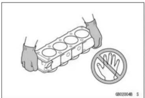
Liftlargeorheavypartswearingglovestopreventinjury frompossiblesharpedgesontheparts.
Solvent
Useahighflushpointsolventwhencleaningparts.High flushpointsolventshouldbeusedaccordingtodirections ofthesolventmanufacturer.
Cleaningvehiclebeforedisassembly
Cleanthevehiclethoroughlybeforedisassembly.Dirtor otherforeignmaterialsenteringintosealedareasduringveh-cledisassemblycancauseexcessivewearanddecrease performanceofthevehicle.

natural_image
Illustration of a hand holding a cylindrical engine block with a no-handled hand symbol nearby (no text or labels)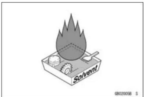
natural_image
Illustration of a calorimeter setup with smoke and components, no text or symbols present
natural_image
Line drawing of a motorcycle with hands adjusting the wheel (no text or symbols)BeforeServicing
ArrangementandCleaningofRemovedParts
Disassembledpartsareeasytoconfuse.Arrangethe partsaccordingtotheorderthepartsweredisassembled andcleanthepartsinorderpriortoassembly.
StorageofRemovedParts
After all the parts including subassembly part have been cleaned, store the parts in a clean area. Put a clean cloth or plastics sheet over the part stop protect from any foreign material that may collect before assembly.
Inspection
Reuseofwornordamagedpartsmayleadtoseriousaccident. Visuallyinspectremovedpartsforcorrosion,discoloration,orotherdamage. Refertotheappropriatesections ofthismanualforservicelimitsonindividualparts. Replace thepartsifanydamagehasbeenfoundorifthepartisbeyonditsservicelimit.
ReplacementParts
ReplacementpartsmustbeKAWASAKIgenuineor recommendedbyKAWASAKI.Gaskets,O-rings,oilseals, greaseseals,circlipsorcotterpinsmustbereplacedwith newoneswheneverdisassembled.
AssemblyOrder
Inmostcasesassemblyorderisthereverseofdisassembly,however,ifassemblyorderisprovidedinthisService Manual,followtheproceduresgiven.

natural_image
Technical line drawing of mechanical components including gears, gears, and a tray (no text or symbols)
natural_image
Technical line drawing of a mechanical assembly with gears and components (no text or symbols)
natural_image
Line drawing of a hand holding a small container with a small inset showing an eye (no text or symbols)

natural_image
Line drawing of hands operating a mechanical device with gears and a handle (no text or symbols)BeforeServicing
TighteningSequence
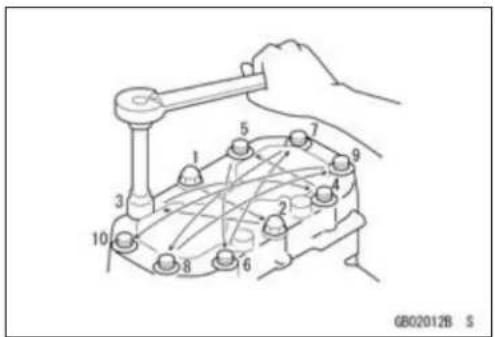
Generally, when installing apart with several bolts, nuts, or screws, start them all in their holes and tightent hem to as nugfit. Thentightenthem according to the specified sequence to prevent casewar page or deformation which can lead to malfunction. Conversely when loosening the bolts, nuts, or screws, first loosen allof them by about a quarter turn and then removethem. If these specified tightening sequence is not indicated, tightent he fasteners alternating diagonally.
Tightening Torque
Incorrect torque applied to a bolt, nut, or screw may lead to serious damage. Tighten fastener stothespecified torque using a good quality torque wrench. Often, the tightening sequence is followed twice - initial tightening and final tightening with torque wrench.
Force
Usecommonsenseduringdisassemblyandassembly, excessive force can cause expensive or hard to repair damage. Whennecessary,removescrewsthathaveanon-permanentlockingagentappliedusinganimpactdriver. Useaplastic-facedmalletwhenevertappingisnecessary.
Gasket, O-ring
Hardening, shrinkage, or damage of both gaskets and O-ringsafterdisassembly can reduce sealing performance. Remove old gaskets and clean these sealing surfaces thoroughly so that nogasket material or other material remains. Install new gaskets and replace used O-rings when re-assembling.
LiquidGasket,LockingAgent
For application that require Liquid Gasketora Locking agent, clean the surfaces so that no oil residue remains before applying liquid gasketor locking agent. Donot apply them excessively. Excessive application can clog oil passages and causes serious damage.

natural_image
Line drawing of hands using a tool to measure a cylindrical object, no text or symbols present
natural_image
Line drawing of a mechanical component being adjusted by a hand (no text or symbols)
natural_image
Line drawing of two hands adjusting flange components with a sun symbol above (no text or symbols)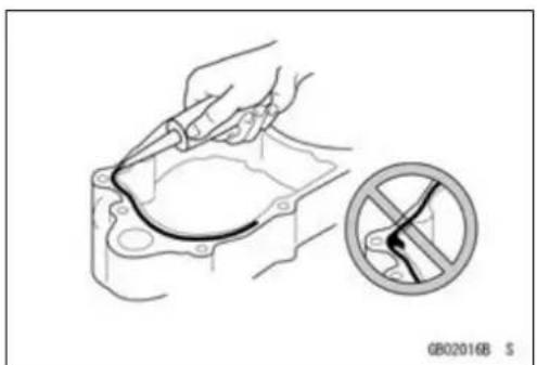
natural_image
Illustration of a hand using a tool to connect components in a mechanical housing, with a no-smoking symbol nearby (no text or labels)BeforeServicing
Press
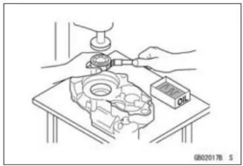
Foritemssuchasbearingsoroilsealsthatmustbe pressedintoplace,applysmallamountofoiltothecontactarea.Besuretomaintainproperalignmentanduse smoothmovementswheninstalling.
BallBearingandNeedleBearing
Donotremovepressedballorneedleunlessremovalis absolutelynecessary.Replacewithnewoneswhenever removed.Pressbearingswiththemanufacturerandsize marksfacingout.Pressthebearingintoplacebyputting pressureonthecorrectbearingraceasshown.
Pressingtheincorrectracecancausepressurebetween theinnerandouterraceandresultinbearingdamage.
OilSeal, GreaseSeal
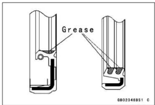
Donotremovepressedoilorgreasesealsunlessremoval isnecessary.Replacewithnewoneswheneverremoved. Pressnewoilsealswithmanufactureandsizemarksfacing out.Makesurethesealisalignedproperlywheninstalling.
Applyspecifiedgreasetothelipofsealbeforeinstalling theseal.
Circlips, CotterPins
Replacecirclipsorcotterpinsthatwereremovedwithnew ones. Takecarenottoopentheclipexcessivelywheninstallingtopreventdeformation.
natural_image
Technical illustration of a mechanical assembly with hands and a small oil meter (no text or symbols)
natural_image
Mechanical assembly diagram showing two mechanical components with downward force arrows, one bearing a circular component (no text or symbols)

natural_image
Technical illustration of a mechanical tool interacting with a workpiece, showing motion and assembly (no text or symbols)1-6GENERALINFORMATION
BeforeServicing
Lubrication
It is important to lubricator rotating or sliding parts during assembly to minimize weard during initial operation. Lubrication points are called out throughout this manual, apply the specific oilorgrease as specified.
DirectionofEngineRotation
Whenrotatingthecrankshaftbyhand, thefreeplay amountofrotatingdirectionwillaffecttheadjustment. Rotatethecrankshafttopositivedirection(clockwiseviewed fromoutputside).
ElectricalLeads
Atwo-colorleadisidentifiedfirstbytheprimarycolorand thenthestripecolor.Unlessinstructedotherwise,electrical leadsmustbeconnectedtothoseofthesamecolor.
Instrument
Useameterthathasenoughaccuracyforanaccurate measurement.Readthemanufacture'sinstructionsthor- oughlybeforeusingthemeter.Incorrectvaluesmaylead toimproperadjustments.

natural_image
Line drawing of hands assembling a tire with a tool labeled 'OIL' (no text or symbols beyond label)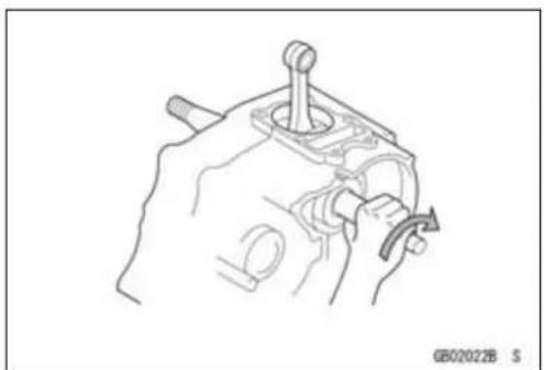
natural_image
Technical line drawing of a mechanical component with no visible text or symbols

natural_image
Line drawing of a hand using a multimeter to test electrical components (no text or symbols visible)ModelIdentification
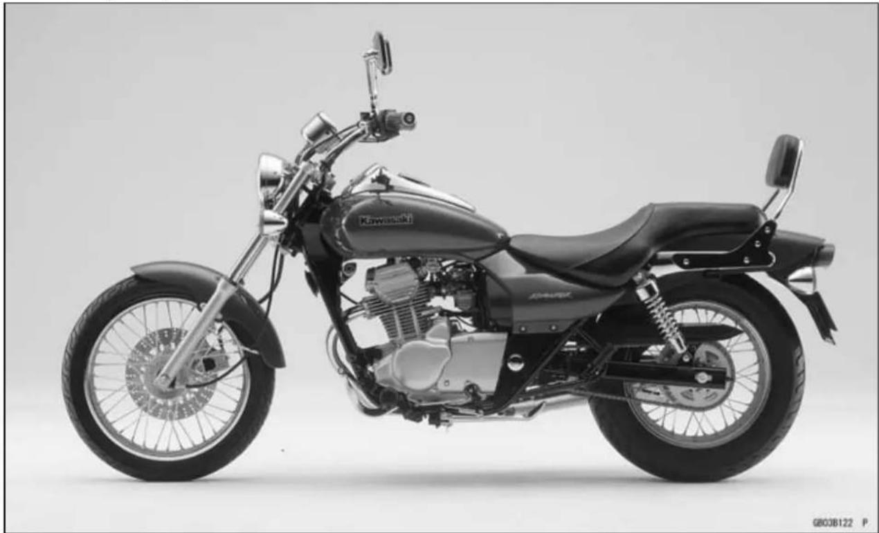
BN125-A1(Europe)LeftSideView
natural_image
Side profile of a black Kawasaki motorcycle with visible engine and wheels (no text or symbols)BN125-A1(Europe)RightSideView
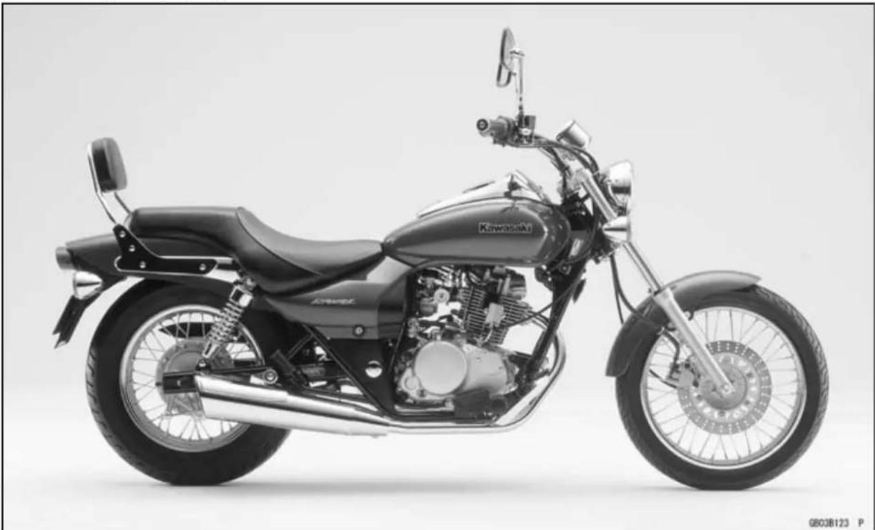
natural_image
Side profile of a black Kawasaki motorcycle with visible engine and wheel (no text or symbols)1-8GENERALINFORMATION
ModelIdentification
BN125-A1(Singapore)LeftSideView

natural_image
Side profile of a black Kawasaki motorcycle with visible engine and wheel (no text or symbols)BN125-A1(Singapore)RightSideView

natural_image
Side profile of a black Kawasaki motorcycle with visible engine, power lines, and wheelbase (no text or symbols)GeneralSpecifications
| Items | BN125-A1 ~ A2 | BN125-A3 ~ A4 | BN125-A5 ~ |
| Dimensions | |||
| Overalllength2150mm(84.6in.) | |||
| Overallwidth780mm(30.7in.) | |||
| Overallheight1020mm(40.2in.) | 1035mm(40.8in.) | ←1050mm(41.3in.)(US,CA)1045mm(41.1in.)BN125-A7~ (N,NU) | |
| Wheelbase1470mm(57.9in.) | |||
| Roadclearance | 145mm(5.7in.)160mm(6.3in.) | ←155mm(6.1in.)(US,CA) | |
| Seatheight680mm(26.8in.) | |||
| Drymass | 128kg(1255N,282lb) | 135kg(1323N,298lb)132kg(1294N,291lb)(US):(BN125-A4~) | |
| Curbmass:Front64kg(628N,141lb)← | 66kg(647N,146lb)(CAL)65kg(637N,143lb)(BN125-A7~,N,NU) | ||
| Rear: | 80 kg (785 N, 176 lb) | 84 kg (824 N, 185 lb)81kg(794N,179lb):(BN125-A4, US,CA) | ←←82kg(804N,181lb)(CAL)83kg(814N,183lb)(BN125-A7~,N,NU) |
| Fueltankcapacity | 13L(3.43USgal) | ||
| Performance | |||
| Minimumturningradius | 2.5m(8.2ft.) | ||
| Engine | |||
| Type | 4-stroke,SOHC,1-cylinder | ||
| Coolingsystem | Air-cooled | ||
| Boreandstroke | 55×52.4mm(2.2×2.1in.) | ||
| Displacement | 124cm3(7.6cuin.) | ||
| Compressionratio | 9.6: 1 | ||
| Maximumhorsepower | 8.8kW(12PS)@9500r/min(rpm),(US)- | ←8.5kW(11.6PS)@9500r/min(rpm)(BN125-A7~,N,NU) | |
GeneralSpecifications
| Items | BN125-A1 ~ A2 | BN125-A3 ~ A4 | BN125-A5 ~ |
| Maximum torque 9.7N·m(0.99kgf·m,7.2ft·lb)@8000r/min(rpm)(US)- | ←9.8N·m(1.00kgf·m,7.2ft·lb)@8000r/min(rpm)(BN125-A7~,N,NU) | ||
| Carburetionsystem CarburetorStartingsystemIgnition systemTiming advanceIgnition timing From 10° BTDC | ,MIKUNIBS28Electric starterDC-CDIElectronically advanced (analog) | ||
| @1300r/min(rpm)to30° BTDC@4500r/min(rpm) | ←From 10° BTDC@1300r/min(rpm) to35° BTDC@4500r/min(rpm)(US,CA,CAL) | ||
| Spark plug NGKCR7E | ← | NGKCR7EorU22ESR-N:(BN125-A4~, US, CA) | |
| Valvetiming:Inlet:OpenCloseDurationExhaust:OpenCloseDurationLubricationsystemEngine oil:Grade | 23° BTDC57° ABDC260°64° BBDC16° ATDC260°Forcedlubrication(wetsump) | ||
| SE, SF or SG | ←(BN125-A3)APISE,SForSGAPISH,SJorSLwithJASOMA | ||
| ViscosityCapacity | SAE10W-40 | ||
| 1.4L(1.48USqt)(whenengine is completely dry) | |||
| Drive TrainPrimary reduction system:TypeReduction ratioClutch typeTransmission:Type | Gear3.666(77/21)Wetmultidisc5-speed,constantmesh,returnshift | ||
GeneralSpecifications
| Items | BN125-A1 ~ A2 | BN125-A3 ~ A4 | BN125-A5 ~ |
| Gear ratios: | |||
| 1st | 2.700(27/10) | ||
| 2nd | 1.705(29/17) | ||
| 3rd1.300(26/20) | |||
| 4th1.090(24/22) | |||
| 5th0.952(20/21) | |||
| Finaldrivesystem: | |||
| TypeChaindrive | |||
| Reduction ratio 3.066(46/15) | ← | 2.800(42/15)(BN125-A7~, N, NU) | |
| Overall drive ratio | 10.708 @Top gear | ←9.778@Topgear(BN125-A7~, N, NU) | |
| Frame | |||
| Type | Doublecradle | ||
| Caster(rake angle) | 34° | ||
| Trail | 121 mm(4.8in.) | ←119 mm (4.7 in.): BN125-A4 ~ (US, CA) | |
| RimSize: | |||
| Front | 17×1.85 | ||
| Rear | 15×2.75 | ||
| Fronttire: | |||
| TypeTubetype | |||
| Size | 90/90-17 M/C49P | ||
| Reartire: | |||
| TypeTubetype | |||
| Size | 130/90-15 M/C66P | ||
| Frontsuspension: | |||
| TypeTelescopic fork | |||
| Wheel travel | 130 mm (5.1 in.) | 140 mm (5.5 in.) | |
| Rearsuspension: | |||
| TypeSwingam | |||
| Wheel travel | 60 mm (2.4 in.) | 80 mm (3.1 in.) | |
| 75mm (3.0in.) | |||
| (BN125-A2~) | |||
| Braketype: | |||
| Front | Singledisc | ||
| Rear | Drum | ||
| Electrical Equipment | |||
| Battery | 12V9Ah | ||
| Headlight: | |||
| TypeSemi-sealed beam | |||
| Bulb | 12V60/55W | ||
1-12GENERALINFORMATION
GeneralSpecifications
| Items | BN125-A1 ~ A2 | BN125-A3 ~ A4 | BN125-A5 ~ |
| Trail/brakelight12V5/21WAlternator:TypeRatedoutput | Single-phaseAC8.75A/12V@4000r/min(rpm):BN125-A115A/14V@8000r/min(rpm):BN125-A2~ | ||
Specificationssubjecttochangewithoutnotice, and may not apply to every country.
(CA):CanadaModel
(US):UnitedStatesModel
(N): NoCatalyticConverter
(NU): No Catalytic Converter (United Kingdom Model)
TechnicalInformation-DC-CDI(DirectCurrent-CapacitorDischargeIgnitionSystem)
Description
○ UnliketheconventionalCDI, the DC-CDlusesabatteryinsteadofamagnetoasapowersource.
The DC-CDI powered by a battery generates strong ignitions parkeven at low engines speeds. The conventional CDI, which uses AC voltages supplied by an exciter coil, generates less ignitions spark at low engines speeds.
The DC-CDI has been built-in DC-DC converter which changes battery voltage or battery-changing voltage into high voltage AC. Even if the battery loses its charge, the DC-CDI can use battery-charging voltage.
TheDC-CDI doesn't have an exciter coil, a power consumer, therefore the battery is charged better.
IgnitionSystem
TheDC-CDisconnectedasshown.

flowchart
graph TD
    A["Alternator"] --> B["Regulator/Rectifier"]
    B --> C["Ignition Switch"]
    C --> D["CDI unit"]
    D --> E["Ignition Coil"]
    E --> F["Spark Plug"]
    F --> G["Battery"]
    G --> H["Crank-shaft Sensor"]
    H --> B
    B --> I["Voltage is detected"]
    I --> J["Engine Stop Switch"]
    J --> D

flowchart
graph TD
    A["Alternator"] --> B["Regulator/Rectifier"]
    B --> C["Ignition Switch"]
    C --> D["CDI unit"]
    D --> E["Ignition Coil"]
    E --> F["Spark Plug"]
    F --> G["Battery"]
    G --> H["Crank-shaft Sensor"]
    B --> I["Voltage is detected"]
    D --> J["Engine Stop Switch"]
1-14GENERALINFORMATION
TechnicalInformation-DC-CDI(DirectCurrent-CapacitorDischargeIgnitionSystem)
Operation
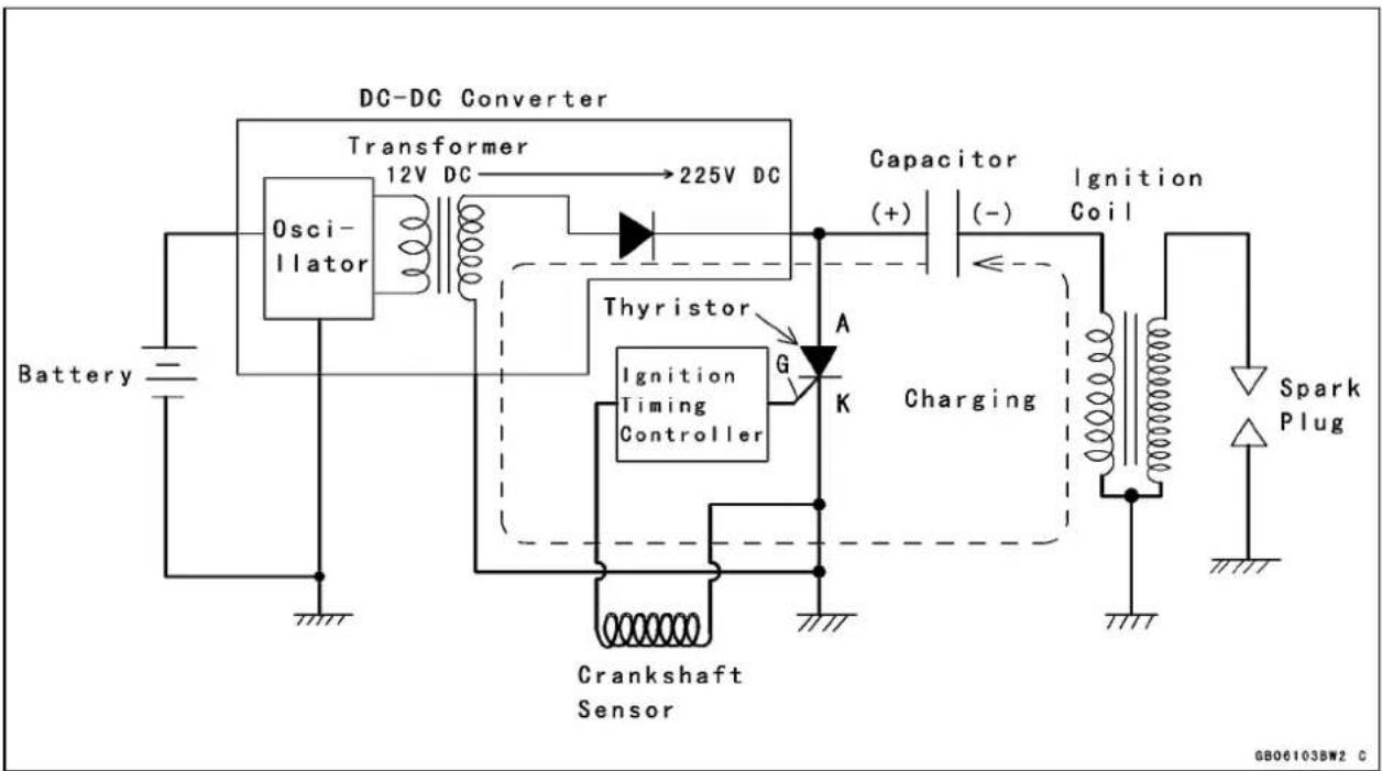
TheDC-CDIcircuitconsistsofabattery,aDC-DCconverter,adiode,acapacitor,anignitiontiming controller, a crankshaft sensor, a thyristor, an ignition coil, a spark plug, an ignition switch, and an enginestopswitch.IftheignitionswitchortheenginestopswitchisturnedtotheOFFposition,the batterypowersupplyiscutoff,andnosparkisgenerated.
TheDC-DCconverterintheCDlunithasabuilt-intransformer,whichchanges12Vbatteryvoltageorbattery-chargingvoltageintoACvoltage.ThediodeconvertstheACvoltageintoabout225VDCtochargethecapacitor.
Firststep-ChargingtheCapacitor
Theconvertergeneratesthecurrenttochargethecapacitorthroughthediodewith225VDC.During thisprocess,thecurrentchangesslowlythroughtheprimarycoilwindingsothatthesecondarycoil windinggoesnotproduceenoughvoltagetofirethesparkplug.
flowchart
graph TD
    A["Battery"] --> B["DC-DC Converter"]
    B --> C["Transformer 12V DC"]
    C --> D["225V DC"]
    D --> E["Capacitor (+)"]
    E --> F["Ignition Coil (-)"]
    F --> G["Charging"]
    G --> H["Crankshaft Sensor"]
    H --> I["Gitation Timing Controller"]
    I --> J["Thyristor"]
    J --> K["A"]
    K --> L["K"]
    L --> M["Spark Plug"]
    style A fill:#f9f,stroke:#333
    style B fill:#ccf,stroke:#333
    style C fill:#cfc,stroke:#333
    style D fill:#fcc,stroke:#333
    style E fill:#cff,stroke:#333
    style F fill:#ffc,stroke:#333
    style G fill:#cfc,stroke:#333
    style H fill:#fcc,stroke:#333
    style I fill:#ffc,stroke:#333
    style J fill:#cfc,stroke:#333
    style K fill:#fcc,stroke:#333
    style L fill:#ffc,stroke:#333
    style M fill:#cfc,stroke:#333
    style_N["Ignition Timing Controller"] --> O["Thyristor"]
    O --> P["A"]
    P --> Q["K"]
Secondstep-thyristorconducts
Aftercharging, the crankshaft sensor and ignition timing controllers send at triggers signal to the gate through the cathode (K → G in the figure) in the thyristor. When this happens, the current flows from the cathodeto the anode (K → A) in the thyristor.
Thirdstep-SurgingcurrentintothePrimaryWinding
Whenthethyristorconducts, the chargestored in the capacitor is released suddenly, flowing through the primary winding, backthrough the ethyristortothecapacitor.
TechnicalInformation-DC-CDI(DirectCurrent-CapacitorDischargeIgnitionSystem)

flowchart
graph TD
    Battery --> DC-DC_Converter["DC-DC Converter"]
    DC-DC_Converter --> Transformer["Transformer 12V DC → 225V DC"]
    Transformer --> Oscillator["Oscillator"]
    Oscillator --> Thyristor["Thyristor"]
    Thyristor --> IgnitionTiming["Ignition Timing Controller"]
    IgnitionTiming --> Crankshaft["Crankshaft Sensor"]
    Crankshaft --> PrimaryWinding["Primary Winding"]
    PrimaryWinding --> Discharging["Discharging"]
    Discharging --> Capacitor["Capacitor (+) (-)"]
    Capacitor --> IgnitionCoil["Ignition Coil"]
    IgnitionCoil --> SparkPlug["Spark Plug"]
    SparkPlug --> SecondaryWinding["Secondary Winding"]
    SecondaryWinding --> Drone["Drone"]
    Drone --> PrimaryWinding
    PrimaryWinding --> G["G"]
    G --> K["K"]
    K --> A["A"]
    A --> G
    style DC-DC_Converter fill:#f9f,stroke:#333
    style Battery fill:#fff,stroke:#333
    style Crankshaft fill:#fff,stroke:#333
    style PrimaryWinding fill:#fff,stroke:#333
    style SecondaryWinding fill:#fff,stroke:#333
    style SparkPlug fill:#fff,stroke:#333
    style Drone fill:#fff,stroke:#333
    style SecondaryWinding fill:#fff,stroke:#333
    style G fill:#fff,stroke:#333
    style K fill:#fff,stroke:#333
    style A fill:#fff,stroke:#333
    style K fill:#fff,stroke:#333
    style G fill:#fff,stroke:#333
    style K fill:#fff,stroke:#333
    style A fill:#fff,stroke:#333
    style K fill:#fff,stroke:#333
    style K fill:#fff,stroke:#333
    style K fill:#fff,stroke:#333
    style K fill:#fff,stroke:#333
    style K fill:#fff,stroke:#333
    style K fill:#fff,stroke:#333
    style K fill:#fff,stroke:#333
    style K fill:#fff,stroke:#334
This sudden change in the primary current induces a primary voltage (counterelectromotive force) which is equal to the capacitor voltage (about 225V) but against the discharging current. The primary voltage induces a high secondary voltage in the secondary coil, generating spark plug gap. The secondary voltage multiplied by winding ratio (about 90:1) reaches about 20000V.
Finalstep-Thyristorresets
After the charge stored in the capacitor is completely released, the cathodeoanode voltage is removed in the thyroid or and the thyroid receptor stops conducting and automatically resets. Then, the DC-DC converter charges the capacitor again and operation return to first step.
The control of Ignition Timing
Sincetheignitiontimingiselectronicallyadvancedorretarded, thissystemhasnomechanicalpartssuchasacam orcontactbreakersandtherearenopartstowearoutand noperiodicmaintenanceisrequired. So, thereisneverany needtoadjustthetimingonceithasbeeninstalledcorrectly.
Generally, the spark plug must be fired at a proper crank angle before top dead center (BTDC).
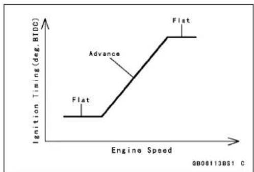
Atlowandmid-rangeenginespeeds, thefastertheengine runs, thefurthertheignitionTimingadvances. This preventsknocking and preignition, and providesbetterengine performance.
Iftheenginespeedincreasesfurther,notimingadvance isrequiredbecausetheenginecanbreatheinandburnthe fuel/airmixtureinashortertime.Theignitiontimingdoes notincreasefurtherandthetimingadvancestops.This alsoprovidesbetterengineperformanceandpreventsthe enginefromoverrunningandoverheating.
Theoperationofadiodeandthyristorisexplainedhere inordertodescribehowtheignitiontimingiscontrolled.

line
| Time (deg.) | Ignition Timing (deg. BTDC) | | :--- | :--- | | low-middle speed | idling | | high speed | |1-16GENERALINFORMATION
TechnicalInformation-DC-CDI(DirectCurrent-CapacitorDischargeIgnitionSystem)
Diode
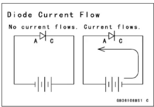
Adiodefunctionsasanelectricalcheckvalve.Itconducts currenteasilyfromitscathodetoitsanode,butitwillnot permitcurrentflowintheoppositedirection.Sinceelectricityattemptstoflowfromnegative(−)topositive(+),acircuitwithadonewillconductcurrentonlywhenthepolarity iscorrect,i.e.,whenthenegativechargeisappliedtothe diode'scathode.
NOTE
○ Thismanual doesn't usethe conventional current flow concept, but the electron theory current flow concept; currentissupposed to flownegative(−)topositive(+) in thistext.

Thyristor(SCR)
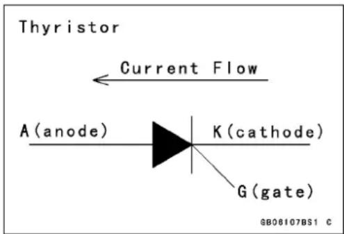
Currentwillflowfromthecathodetoanodebutwillnot flowinthereversedirection. Thethyristordiffersfroma diodeintworespects:(a)eventhoughavoltageofthecorrectpolarity-negativetocathode-maybeapplied,thethyristorwillnotconductuntilasignalisappliedtothegateinput lead;(b)oncestarted,itwillnotstopconducting(evenifthe gateleadsignalvoltagestops)untilthecathodetoanode voltageisremovedorreversed.
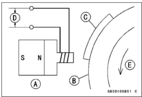
Thecrankshaftsensorisinstalledonthealternatorcover sothatitwillbeclosetothealternatorrotor. Onesideof thecrankshaftsensorcorehasapermanentmagnetand theothersidehasacoiltosignaltheCDlunit.
CrankshaftSensor[A]
AlternatorRotor[B]
TimingPlate[C]
OutputVoltage[D]
TechnicalInformation-DC-CDI(DirectCurrent-CapacitorDischargeIgnitionSystem)
Everytimeeitherendofthetimingplateontherotor passesbythecrankshaftsensor,apulseisgeneratedand senttotheCDIunit,thatis,twopulsesaregeneratedper onerevolutionoftherotor.Oneisapositivepulse[A]and theotherisanegativepulse[B].
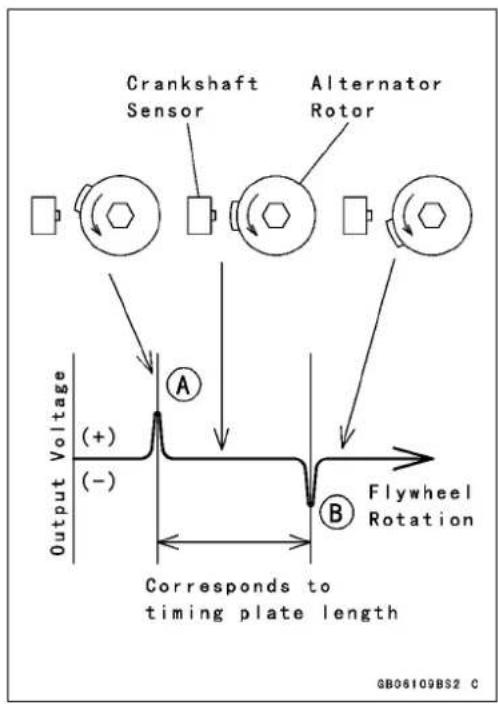
Thecrankshaftsensor,asignalgenerator,andvoltagecomparatorsdeterminetheignitiontimingintheignitiontimingcontroller.Thepowersupplycircuitisthepowersourceforthesignalgeneratorandthevoltagecomparators.

flowchart
graph LR
    A["Crankshaft Sensor"] --> B["Signal Generator"]
    B --> C["A Signal"]
    B --> D["B Signal"]
    C --> E["Comparator"]
    D --> E
    E --> F["Power Supply Circuit"]
    F --> G["Thyristor"]
    G --> H["K"]
    I["G"] --> G
1-18GENERALINFORMATION
TechnicalInformation-DC-CDI(DirectCurrent-CapacitorDischargeIgnitionSystem)
Thecrankshaftsensorgeneratesacrankshaftsensorsignalandsendsittothesignalgenerator. ThesignalgeneratorgeneratesAandBsignalssynchronizedwiththecrankshaftsensorsignal.Thesesignalsareshowninthefigure.
Thatistosay, the signal generator changesthe crank-shaftsensorsignal into A and B signals.

TechnicalInformation-DC-CDI(DirectCurrent-CapacitorDischargeIgnitionSystem)
(IgnitionTimingAdvancing)
AsignalandBsignalinthecomparatoradvancetheignitiontiming.
ThesignalgeneratordecreasesAsignalastheengine rpmincreasesfromN1,toN3asshown,butkeepsBsignal unchanged.
AandBsignalsareshownwiththesignalsoverlapped.
The comparator compares Asignal with Bsignal. When Asignal voltage becomes equal to or less than Bsignal voltage, the comparators sends atriggersignal to the gate in the thyristor, firing the spark plug.
The intersection point between A and B signals indicates the timing when the spark plug fires. This point moves left (the timing advances) asthe enginerp min increases from N1 to N3 as shown.
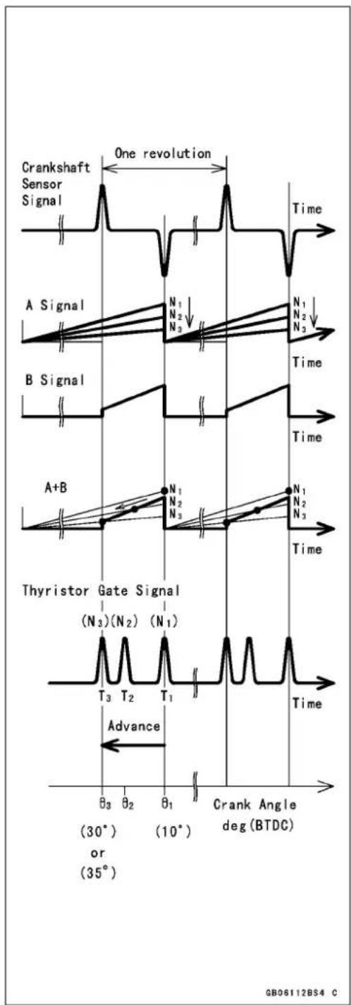
Beforeorafteradvancingperiod,theignitiontimingisdeterminedbythecrankshaftssensorsignalandtheignition timingremainsconstant.
The figureshowstheadvancingchart.
line
| Engine Speed | Ignition Timing (deg.BTDC) | | :--- | :--- | | Flat | Flat | | Advance | Advance | | Flat | Flat |1-20GENERALINFORMATION
TechnicalInformation-CoastingEnricher
Thecoastingenricher[A]preventsbackfiringduringenginebrakingbysupplyingarichfuelmixturetotheengine.

natural_image
Close-up of a mechanical component with threaded end and labeled point A (no readable text or symbols)Whenthemotorcycleiscruisingoraccelerating, theenginevacuumislow, andthereturnspring[3] pushesthevalveinitsopenedposition[5]. Thepassage[6]isopenandtheairrunsthroughthepilot jet[7]forbetteratomization.
Duringenginebraking,ahhighvacuumisgeneratedbehindthebutterflyvalve[11]. Thisdrawsthe diaphragm[2]againstthereturnspring[3]toclosethevalve[12],andthenthepassage[6]. The mixturebecomesrichtopreventbackfiringbecausetheamountofairisreduced.

GB060153W3 C
- PilotAirJet1
2.Diaphragm
- ReturnSpring
4.Cover
- ValveOpened
6.Passage
7.PilotJet
8.PilotAirJet2
9.PilotScrew
10.AirCleanerHousing
- ButterflyValve(ThrottleValve)
12ValveClosed
TechnicalInformation-CoastingEnricher
FuelandAirSupplyofEnricherSystem

flowchart
graph TD
    A["Fuel Tank"] --> B["Float Bowl"]
    B --> C["Main Jet"]
    D["Air Cleaner"] --> E["Carburetor Bore"]
    E --> F["Engine"]
    G["Pilot Air Jet1"] --> H["Pilot Jet"]
    I["Pilot Air Jet2"] --> H
    J["Bypass Outlet"] --> H
    K["Pilot Screw"] --> H
    L["Slow Passage"] --> H
    H --> M["Fuel"]
    H --> N["Mixture"]
    H --> O["Air"]
1-22GENERALINFORMATION
UnitConversionTable
PrefixesforUnits
| PrefixSymbolPower | |
| megaM×1000000kilok×1000centic× 0 . 0 1millim×0.001microp×0.000001 |
UnitsofMass
| kg | × | 2.205 | = | lb |
| g | × | 0.03527 | = | oz |
UnitsofVolume
| L | × | 0.2642 | = | gal(US) |
| L | × | 0.2200 | = | gal(imp) |
| L | × | 1.057 | = | qt(US) |
| L | × | 0.8799 | = | qt (imp) |
| L | × | 2.113 | = | pint (US) |
| L | × | 1.816 | = | pint (imp) |
| mL | × | 0.03381 | = | oz(US) |
| mL | × | 0.02816 | = | oz(imp) |
| mL | × | 0.06102 | = | cu in |
UnitsofForce
| N | × | 0.1020 | = | kg |
| N | × | 0.2248 | = | lb |
| kg | × | 9.807 | = | N |
| kg | × | 2.205 | = | lb |
UnitsofLength
| km | × | 0.6214 = | mile |
| m× | 3.281 = ft | ||
| mm | × | 0.03937 = | in |
UnitsofTorque
| N·m | × | 0.1020 | = | kgf·m |
| N·m | × | 0.7376 | = | ft·lb |
| N·m | × | 8.851 | = | in·lb |
| kgf·m | × | 9.807 | = | N·m |
| kgf·m | × | 7.233 | = | ft·lb |
| kgf·m | × | 86.80 | = | in·lb |
UnitsofPressure
| kPa | × | 0.01020 | = | kgf/cm2 |
| kPa | × | 0.1450 | = | psi |
| kPa | × | 0.7501 | = | cm Hg |
| kgf/cm2 | × | 98.07 | = | kPa |
| kgf/cm2 | × | 14.22 | = | psi |
| cm Hg | × | 1.333 | = | kPa |
UnitsofSpeed
| km/h | × | 0.6214 | = | mph |
UnitsofPower
| kW× | 1.360 | = | PS | |
| kW× | 1.341 | = | HP | |
| PS | × | 0.7355 | = | kW |
| PS | × | 0.9863 | = | HP |
Units of Temperature

line
| Time (°C) | Value | |---|---| | -40 | -20 | | -20 | -4 | | -17.8 | 0 | | 0 | 20 | | 4.4 | 32 | | 20 | 60 | | 26.7 | 68 | | 40 | 80 | | 48.9 | 104 | | 60 | 120 | | 71.1 | 140 | | 80 | 160 | | 93.3 | 176 | | 100 | 180 | | 116 | 200 | | 120 | 212 | | 128 | 248 | | 138 | 260 | | 140 | 284 | | 160 | 300 | | 160 | 320 |PeriodicMaintenance
TableofContents
PeriodicMaintenanceChart....2-2
TorqueandLockingAgent......2-4
Specifications....2-9
SpecialTools....2-11
PeriodicMaintenanceProcedures.....2-12
FuelSystem....2-12
FuelHoseandConnection Inspection....2-12
ThrottleGripFreePlayInspection2-12
ThrottleGripFreePlay Adjustment.....2-13
IdleSpeedInspection....2-13
IdleSpeedAdjustment.....2-14
AirCleanerElementCleaning.....2-14
EvaporativeEmissionControl SystemInspection(CAL)......2-14
EngineTop....2-15
AirSuctionValveInspection......2-15
CylinderHeadBoltTightness Inspection....2-16
ValveClearanceInspection......2-16
ValveClearanceAdjustment.....2-17
Clutch....2-17
ClutchLeverFree Play Inspection2-17
ClutchLeverFreePlay Adjustment.....2-17
EngineLubricationSystem....2-18
EngineOilChange....2-18
OilFilterChange 2-19
OilScreenCleaning 2-20
Wheels/Tires....2-21
Spoke Tightness Inspection .....2-21
RimRunoutInspection......2-21
AirPressureInspection/Adjustment....2-22
TireWearInspection 2-23
FinalDrive....2-23
DriveChainSlackInspection......2-23
DriveChainSlackAdjustment.....2-24
DriveChainWear Inspection .....2-25
Drive ChainLubrication....2-26
Brakes....2-26
Brake PedalFree Play Inspection2-26
BrakeShoeLiningWear Inspection....2-27
Brake PadWearInspection.....2-27
BrakeHoseandConnection Inspection....2-27
Brake FluidLevelInspection......2-28
Brake FluidChange....2-28
Brake LineBleeding....2-29
Brake/Master CylinderCup and Dust SealReplacement....2-31
CaliperPiston/DustSeals Replacement....2-31
Brake LightSwitchInspection.....2-31
Brake CableReplacement......2-31
Suspension....2-32
Front ForkOilChange......2-32
Front ForkOilLeakInspection.....2-33
Rear Shock AbsorberOil Leak Inspection....2-33
Swingarm PivotLubrication......2-33
Steering....2-34
Steering Inspection....2-34
Steering Adjustment....2-34
SteeringStemBearing Lubrication....2-35
Electrical System 2-35
BatteryElectrolyteLevel Inspection.....2-35
Spark PlugCleaning/Inspection...2-35
Spark PlugGapInspection......2-35
General Lubrication....2-36
Lubrication....2-36
Nut, Bolt, and Fastener Tightness Inspection....2-37
Tightness Inspection....2-37
PeriodicMaintenanceChart
Thescheduledmaintenancemustbedoneinaccordancewiththischarttokeepthemotorcyclein good running condition. The initial maintenance is vitally important and must not be neglected.
| FREQUENCY | * O D O M E T E READING ×1000km (×1000mile) | |||||||
| Whichever comesfirst → | ||||||||
| ↓ Every | 161 (0.6) | 2182 (4) | 4303 (7.5) | 6 (12) | (15) | (20) | (24) | |
| Fuelhose,connections-inspect† | ● | ● | ● | ● | ● | ● | ||
| Throttlegripplay-inspect† | ● | ● | ● | ● | ||||
| Idlespeed-inspect | ● | ● | ● | ● | ||||
| Aircleanerelement-clean†# | ● | ● | ● | |||||
| Evaporativeemissioncontrolsystem (CAL)-inspect† | ● | ● | ● | ● | ● | ● | ● | |
| Airsuctionvalve-inspect(ATCH,DE,SI,US) | ● | ● | ● | ● | ● | ● | ||
| Cylinderheadbolttightness-inspect† | ● | ● | ● | ● | ||||
| Valveclearance-inspect† | ● | ● | ● | |||||
| Clutch-adjust | ● | ● | ● | ● | ● | ● | ● | |
| Engineoil-change# | 6month | ● | ● | ● | ● | ● | ● | ● |
| Oilfilter-replace | ● | ● | ● | ● | ||||
| Oilscreen-clean | ● | ● | ● | ● | ||||
| Spoketightnessandrimrunout-inspect† | ● | ● | ● | ● | ● | ● | ● | |
| Tirewear-inspect† | ● | ● | ● | ● | ● | ● | ||
| Drivechainslack-inspect†# | 1000km | |||||||
| Drivechainwear-inspect†# | ● | ● | ● | ● | ● | ● | ||
| Drivechain-lubricate# | 600km | |||||||
| Brakepedalfreeplay-inspect† | ● | ● | ● | ● | ● | ● | ● | |
| Brakeliningorpadwear-inspect†# | ● | ● | ● | ● | ● | ● | ||
| Brakehose,connections-inspect† | ● | ● | ● | ● | ● | ● | ||
| Brakefluidlevel-inspect† | month | ● | ● | ● | ● | ● | ● | ● |
| Brakefluid-change | 2years | ● | ||||||
| Brakemastercylindercupanddust cover-replace | 4years | |||||||
| Caliperfluidsealanddustseal-replace | 4years | |||||||
| Brakelightswitch-inspect† | ● | ● | ● | ● | ● | ● | ● | |
| Brakecable-replace | 2years | ● | ||||||
| Frontforkoil-change | 2years | ● | ||||||
| Frontforkoilleak-inspect† | ● | ● | ● | |||||
| Rearshockabsorberoilleak-inspect† | ● | ● | ● | |||||
| Swingarmpivot-lubricate | ● | ● | ● | |||||
| Steering-inspect† | ● | ● | ● | ● | ● | ● | ● | |
| Steeringstembearing-lubricate | 2years | ● | ||||||
| Batteryelectrolytelevel-inspect† | 6months | ● | ● | ● | ● | ● | ● | |
PeriodicMaintenanceChart
| FREQUENCY | * O D O M E T E R READING ×1000km (×1000mile) | |||||||
| Whichever comesfirst → | ||||||||
| ↓ Every | 161(0.6) | 2182(4) | 43036(7.5) | (12) | (15) | (20) | (24) | |
| Operation | ||||||||
| Sparkplug-cleanandgap† | ● | ● | ● | ● | ● | ● | ||
| Generallubrication-perform | ● | ● | ● | |||||
| Nuts,bolts,andfastenerstightness-inspect | ● | ● | ● | ● | ||||
: Service more frequently when operating in severe conditions; dusty, wet, muddy, high speed, or frequent starting/stopping.
*: For higher odometer readings, repeat at the frequency interval established here.
†: Replace, add, adjust, clean, ortorque if necessary.
AT: Austria
CAL: California
CH: Switzerland
DE: Germany
SG: Singapore
US: United States
TorqueandLockingAgent
The following tables list the tightening torque for them major fasteners requiring use of a non-permanent locking agentor liquid gasket.
Lettersusedinthe"Remarks"columnmean:
L: Applyanon-permanentlockingagenttothethreads.
M:Applymolybdenumdisulfidegrease.
O: Applyanoiltothethreadsandseatingsurface.
S: Tightenthefasteners following the specified sequence.
| Fastener | Torque | Remarks | ||
| N·mkgf | mft·lb | |||
| FuelSystem | ||||
| UpperChamberCoverScrews3.50.3631in·lb | ||||
| SpringSeatScrews | 0.80.08 | 07 in · lb | ||
| ChokeLeverSetScrew | 0.8 | 0.080 | 7 in·lb | L |
| ChokeLeverPivotScrew | 2.00.20 | 17in·lb | ||
| PilotAirJet | 1.80.1815 | in·lb | ||
| Coasting Enricher Cover Screws | 2.0 | 0.20 | 17 in·lb | |
| PilotJet | 0.80.0807 | in · lb | ||
| MainJet | 1.80.1815 | in·lb | ||
| FloatValveHolderScrew | 2.00.20 | 17in·lb | ||
| ChokePlungerCap | 3.90.40 | 35in·lb | ||
| FloatBowlScrews | 2.00.20 | 17in·lb | ||
| CarburetorDrainPlug | 2.00.20 | 17in·lb | ||
| FuelTapPlateScr ews | 0.80.08 | 07 in · lb | ||
| Fuel Tap Diaphragm Cover Screws | 1.0 | 0.10 | 9 in·lb | |
| FuelTapMountingBolts(WhiteWasher) | 2.50.2522 | in·lb | ||
| FuelTapMountingBolts(BlackWasher) | 4.90.5043 | in·lb | ||
| EngineTopEnd | ||||
| ValveAdjustingCapBolts(Bn125-A1~ A3) | 9.8 | 1.0 | 87in·lb | |
| ValveAdjusting gCapBolts(BN125-A4~) | 8.80.90 | 78in·lb | ||
| Camshaft Chain Cover Bolts (BN125-A1 ~ A3) | 9.8 | 1.0 | 87 in·lb | |
| Camshaft Chain Cover Bolts (BN125-A4 ~) | 8.8 | 0.90 | 78 in·lb | |
| Cylinder Head Bolts M9 | 26 | 2.7 | 19 | O, M, S(washer) |
| CylinderHeadBoltsM6 | 12 | 1.2104in·lb | S | |
| CamshaftChainCoverDamperBolts(BN125-A1~ A3) | 9.8 | 1.0 | 87in·lb | |
| CamshaftChainCoverDamperBolts(BN125-A4~) | 8.80.90 | 78in·lb | ||
| Sparkplug | 13 | 1.3 | 9.5 | |
| Cylinder Head Blank Cap Bolt (BN125-A1 ~ A3) | 9.8 | 1.0 | 87in·lb | |
| CylinderHeadBlankCapBolt(BN125-A4~) | 8.80.90 | 78in·lb | ||
| CarburetorHolderBolts | 9.8 | 1.0 | 87in·lb | |
| Air Suction Valve Cover Bolts (BN125-A1 ~ A3) | 9.8 | 1.0 | 87in·lb | |
| AirSucti onValveCoverBolts(BN125-A4~) | 8.80.90 | 78in·lb | ||
| CylinderHeadPlug | 4.90.5043 | in·lb | ||
| VacuumHoseFitting | 5.90.6052 | in·lb | ||
- Motorcycle ServiceManual
- QuickReferenceGuide
- EMISSIONCONTROLINFORMATION
- NOTE
- WERECOMMENDTHATALLDEALERSOBSERVETHESEPROVISIONSOFFEDERALLAW, THEVIOLATIONOFWHICHISPUNISHABLEBYCIVILPENALTIESNOTEXCEEDING \$10,000PERVIOLATION.
- TAMPERINGWITHNOISECONTROLSYSTEMPROHIBITED
- Foreword
- HowtoUseThisManual
- WARNING
- CAUTION
- GeneralInformation
- TableofContents
- 1-2GENERALINFORMATION
- BeforeServicing
- BatteryGround
- EdgesofParts
- Solvent
- Cleaningvehiclebeforedisassembly
- ArrangementandCleaningofRemovedParts
- StorageofRemovedParts
- Inspection
- ReplacementParts
- AssemblyOrder
- TighteningSequence
- Tightening Torque
- Force
- Gasket, O-ring
- LiquidGasket,LockingAgent
- Press
- BallBearingandNeedleBearing
- OilSeal, GreaseSeal
- Circlips, CotterPins
- 1-6GENERALINFORMATION
- Lubrication
- DirectionofEngineRotation
- ElectricalLeads
- Instrument
- ModelIdentification
- 1-8GENERALINFORMATION
- 1-12GENERALINFORMATION
- TechnicalInformation-DC-CDI(DirectCurrent-CapacitorDischargeIgnitionSystem)
- Description
- IgnitionSystem
- 1-14GENERALINFORMATION
- Operation
- Firststep-ChargingtheCapacitor
- Secondstep-thyristorconducts
- Thirdstep-SurgingcurrentintothePrimaryWinding
- Finalstep-Thyristorresets
- The control of Ignition Timing
- 1-16GENERALINFORMATION
- Diode
- Thyristor(SCR)
- 1-18GENERALINFORMATION
- 1-20GENERALINFORMATION
- TechnicalInformation-CoastingEnricher
- 1-22GENERALINFORMATION
- UnitConversionTable
- Units of Temperature
- PeriodicMaintenance
- PeriodicMaintenanceChart
- : Service more frequently when operating in severe conditions; dusty, wet, muddy, high speed, or frequent starting/stopping.
- TorqueandLockingAgent
Brand : MITSUBISHI
Model : Eliminator 125 (2004)
Category : Motorcycle