
ProCurve MSM317 - Access Point HP - Free user manual and instructions
Find the device manual for free ProCurve MSM317 HP in PDF.


| Product Type | Managed Dual-Radio 802.11a/b/g/n Access Point |
| Wireless Standards | IEEE 802.11a, 802.11b, 802.11g, 802.11n |
| Frequency Bands | 2.4 GHz and 5 GHz |
| Maximum Data Rate | Up to 300 Mbps (2x2 MIMO) |
| Ethernet Interface | 1x 10/100/1000 Base-T (RJ-45) with PoE |
| Power Supply | Power over Ethernet (802.3af) or optional 12V DC adapter |
| Power Consumption | 12.95 W (typical) |
| Dimensions (W x D x H) | 160 x 160 x 35 mm |
| Weight | 0.35 kg |
| Antenna Type | Two internal dual-band antennas (2x2) |
| Management | Centralized via HP MSM7xx Controller (controlled mode) or standalone (autonomous mode) with web GUI |
| Security | WEP, WPA/WPA2-Personal, WPA/WPA2-Enterprise (802.1X), MAC filtering, VLAN support |
| Quality of Service | WMM, bandwidth control, traffic prioritization |
| Mounting | Ceiling or wall mount (kit included) |
| Operating Temperature | 0°C to 40°C |
| Operating Humidity | 5% to 95% (non-condensing) |
| LED Indicators | Power, Ethernet, 2.4 GHz radio, 5 GHz radio |
| Compliance | FCC, CE, IC, RoHS |
Frequently Asked Questions - ProCurve MSM317 HP
User questions about ProCurve MSM317 HP
0 question about this device. Answer the ones you know or ask your own.
Ask a new question about this device
Download the instructions for your Access Point in PDF format for free! Find your manual ProCurve MSM317 - HP and take your electronic device back in hand. On this page are published all the documents necessary for the use of your device. ProCurve MSM317 by HP.
USER MANUAL ProCurve MSM317 HP
HP MSM7xx Controllers Configuration Guide
Abstract
This document describes how to configure and manage the MSM7xx Controllers. This document applies to the MSM710, E-MSM720, MSM760, and MSM765zl Controllers. These products are hereafter referred to generically as controller.
© Copyright 2011 Hewlett-Packard Development Company, L.P.
The information contained herein is subject to change without notice. The only warranties for HP products and services are set forth in the express warranty statements accompanying such products and services. Nothing herein should be construed as constituting an additional warranty. HP shall not be liable for technical or editorial errors or omissions contained herein.
Acknowledgments
Windows® is a U.S. registered trademark of Microsoft Corporation.

Warranty
WARRANTY STATEMENT: See the warranty information sheet provided in the product box.
Contents
1 Introduction....13
New in this release....13
2 Using the management tool....14
Starting the management tool....14
Using automated workflows....14
Setting up manager and operator accounts....16
Administrative user authentication....18
Passwords....19
Configuring management tool security....19
Configuring the Login page message....20
Configuring Auto-refresh....21
Setting the system time....21
3 Network configuration....22
Working with network profiles....22
About the default network profiles....22
To define a new network profile....23
Configuring IP interfaces....23
To assign an IP address to a new interface on the E-MSM720....24
To assign an IP address to a new interface on other controllers....26
Configuring the Access network/LAN port interface....28
Configuring the Internet network/Internet port interface....29
Configuring port settings....32
Configuring E-MSM720 ports....33
Configuring the LAN/Internet port (MSM710, MSM760, MSM765zl)....34
Configuring DHCP services....34
Configuring the global DHCP server....35
Configuring the DHCP relay agent....38
Configuring GRE tunnels....39
Bandwidth control....40
Data rate limits....41
Bandwidth levels....41
Example....42
Discovery protocols....43
CDP configuration....43
LLDP configuration....44
DNS configuration....47
DNS servers....48
DNS advanced settings....48
Defining IP routes....49
Configuring IP routes....49
Network address translation (NAT)....51
NAT security and static mappings....52
VPN One-to-one NAT....54
IP QoS....54
Configuring IP QoS profiles....54
Example....55
Customizing DiffServ DSCP mappings....57
IGMP proxy....57
4 Port trunking....59
Deployment considerations....60
Static trunks....61
Dynamic trunks....61
Creating a static trunk....61
Creating a dynamic trunk....64
5 Wireless configuration....69
Wireless coverage....69
Factors limiting wireless coverage....69
Configuring overlapping wireless cells....70
Automatic transmit power control....73
Supporting 802.11a and legacy wireless clients....73
Radio configuration....74
Radio configuration parameters....75
Advanced wireless settings....85
Wireless neighborhood....89
Scanning modes....90
Identifying unauthorized APs....90
Viewing wireless information....90
Viewing all wireless clients....90
Viewing info for a specific wireless client....91
Viewing wireless client data rates....92
Wireless access points....94
6 Working with VSCs....98
Key concepts....98
Binding VSCs to APs....98
Viewing and editing VSC profiles....98
The default VSC....99
VSC configuration options....99
About access control and authentication....100
Summary of VSC configuration options....102
Access control....102
Virtual AP....103
VSC ingress mapping....108
VSC egress mapping....109
Bandwidth control....109
Default user data rates....109
Wireless mobility....110
Fast wireless roaming....111
Wireless security filters....111
Wireless protection....114
802.1X authentication....116
RADIUS authentication realms....117
HTML-based user logins....118
VPN-based authentication....118
MAC-based authentication....118
Location-aware....119
Wireless MAC filter....119
Wireless IP filter....119
DHCP server....120
DHCP relay agent....120
VSC data flow....121
Access control enabled....121
Access control disabled....123
Using multiple VSCs....124
About the default VSC....124
Quality of service (QoS)....125
Priority mechanisms....126
IP QoS profiles....127
Upstream DiffServ tagging....127
Upstream/downstream traffic marking....127
QoS example....129
Creating a new VSC....129
Assigning a VSC to a group....129
7 Working with controlled APs......130
Key concepts....130
Plug and play installation....130
Automatic software updates....130
Centralized configuration management....130
Manual provisioning....130
Secure management tunnel....130
AP authentication....130
AP licensing....131
Key controlled-mode events....131
Discovery of controllers by controlled APs....133
Discovery overview....133
Discovery methods....134
Discovery order....135
Discovery recommendations....136
Discovery priority....137
Discovery considerations....138
Monitoring the discovery process....139
Authentication of controlled APs....143
Building the AP authentication list....143
Configuring APs....145
Overview....145
Inheritance....146
Configuration strategy....147
Working with groups....147
Working with APs....149
Assigning egress VLANs to a group....153
Assigning country settings to a group....153
Provisioning APs....153
Provisioning methods....154
Displaying the provisioning pages....154
Provisioning connectivity....155
Provisioning discovery....158
Provisioning summary....159
Provisioning example....159
AeroScout RTLS....160
To enable AeroScout support....160
Viewing status information....161
Software retrieval/update....161
Monitoring....162
8 Working with VLANs....163
Key concepts....163
VLAN usage....163
Defining a VLAN....164
Defining a VLAN on a controller port....164
Assigning VLANs to controlled APs....165
User-assigned VLANs....166
VLAN assignment via RADIUS....166
VLAN assignment via the local user accounts....166
Traffic flow for wireless users....166
Binding to a VSC that has Wireless mobility disabled....167
Binding to a VSC that has Wireless mobility and Mobility traffic manager enabled....169
Binding to a VSC that has Wireless mobility and Subnet-based mobility enabled....170
Terms used in the tables....171
Traffic flow examples....171
9 Controller teaming....175
Teaming overview....175
Teaming On the MSM760 and MSM765zl 175
Teaming on the E-MSM720....175
Key concepts....175
Centralized configuration management....175
Centralized monitoring and operation....176
Redundancy and failover support....176
Scalability....176
Deployment considerations....176
Limitations....178
Creating a team....178
About the team IP address....179
Configuration examples....179
Controller discovery....191
Monitoring the discovery process....192
Viewing discovered controllers....194
Viewing team members....195
Team configuration....196
Accessing the team manager....196
Team configuration options....197
Removing a controller from a team....197
Editing team member settings....198
Discovery of a controller team by controlled APs....200
Failover....200
Supporting N + N redundancy....200
Primary team manager failure....201
Mobility support....202
Single controller team operating alone....203
Single controller team operating with non-teamed controllers....204
Multiple teamed and non-teamed controllers....205
10 Mobility traffic manager....206
Key concepts....206
The mobility domain....208
Home networks....209
Local networks....210
Mobility controller discovery....210
Network requirements....211
Controller discovery and teaming....211
Configuring Mobility Traffic Manager....211
Defining the mobility domain....212
Defining network profiles....213
Assigning a home network to a user....213
Defining local networks on a controller....214
Assigning local networks to an AP....214
Configuring the mobility settings for a VSC....215
Binding a VSC to an AP....216
Monitoring the mobility domain....216
Controllers....217
Networks in the mobility domain....217
Mobility clients....218
Forwarding table....218
Mobility client event log....219
Scenario 1: Centralizing traffic on a controller....220
How it works....220
Configuration overview....221
Scenario 2: Centralized traffic on a controller with VLAN egress....222
How it works....222
Configuration overview....223
Scenario 3: Centralized traffic on a controller with per-user traffic routing......225
How it works....225
Configuration overview....226
Scenario 4: Assigning home networks on a per-user basis....233
How it works....233
Configuration overview....234
Scenario 5: Traffic routing using VLANs....237
How it works....237
Configuration overview....239
Scenario 6: Distributing traffic using VLAN ranges....244
How it works....244
Configuration overview....246
Subnet-based mobility....251
11 User authentication, accounts, and addressing......252
Introduction....252
Authentication support....252
Other access control methods....254
Using more than one authentication type at the same time....254
User authentication limits....256
802.1X authentication....256
Supported 802.1X protocols....257
Configuring 802.1X support on a VSC....258
Configuring global 802.1X settings for wired users....260
Configuring global 802.1X settings for wireless users....260
Configuring 802.1X support on an MSM317 switch port....261
MAC-based authentication....261
MAC-based filtering....262
Configuring global MAC-based authentication....263
Configuring MAC-based authentication on a VSC....264
Configuring MAC-based authentication on an MSM317 switch port....265
Configuring MAC-based filters on a VSC....265
Configuring MAC-based filters on an MSM317 switch port....266
HTML-based authentication....268
Configuring HTML-based authentication on a VSC....268
VPN-based authentication....269
Configuring VPN-based authentication on a VSC....269
No authentication....270
Locally-defined user accounts....270
Features....271
Defining a user account....275
Defining account profiles....277
Defining subscription plans....278
Accounting persistence....279
User addressing and related features....280
12 Authentication services....281
Introduction....281
Using the integrated RADIUS server....281
Primary features....281
Server configuration....282
User account configuration....283
Using a third-party RADIUS server....283
Configuring a RADIUS server profile....284
Authenticating manager logins using a third-party RADIUS server....288
Using an Active Directory server....288
Supported protocols....289
Active Directory configuration....289
Configuring an Active Directory group....291
Configuring a VSC to use Active Directory....293
13 Security....294
Firewall....294
Firewall presets....294
Firewall configuration....295
Customizing the firewall....296
Managing certificates....296
Trusted CA certificate store....297
Certificate and private key store....298
Certificate usage....300
About certificate warnings....301
IPSec certificates....301
Certificate expiration alerts....303
MAC lockout....303
Adding a MAC lockout address....303
14 Local mesh....304
Key concepts....304
Simultaneous AP and local mesh support....304
Using 802.11a/n for local mesh....305
Local mesh terminology....305
Local mesh operational modes....306
Node discovery....306
Operating channel....306
Local mesh profiles....307
Configuration guidelines....307
Configuring a local mesh profile....307
Provisioning local mesh links....311
Sample local mesh deployments....313
RF extension....313
Building-to-building connection....314
Dynamic network....314
15 Public/guest network access....316
Introduction....316
Key concepts....316
Access control....316
Access lists....317
The public access interface....317
Location-aware....319
Configuring global access control options....319
User authentication....320
Client polling....321
User agent filtering....322
Zero configuration....322
Location configuration....322
Display advertisements....323
Public access interface control flow....323
Customizing the public access interface....325
Sample public access pages....326
Common configuration tasks....326
Setting site configuration options....329
About ASP variables....329
Allow subscription plan purchases....329
Display the Free Access option....330
Support a local Welcome page....331
Use frames when presenting ads....331
Allow SSLv2 authentication....332
Redirect users to the Login page via....332
Customizing the public access Web pages....332
Site file archive....332
FTP server....333
Current site files....334
Configuring the public access Web server....339
Options....339
Ports....340
MIME types....340
Security....341
Managing payment services....341
Payment services configuration....341
Service settings....342
Billing record logging....347
Settings....348
Persistence....348
External billing records server profiles....349
Billing records log....351
Table....351
Location-aware authentication....352
How it works....352
Example....353
Security....354
16 Working with RADIUS attributes....355
Introduction....355
Controller attributes overview....355
Customizing the public access interface using the site attribute....355
Defining and retrieving site attributes....356
Controller attribute definitions....358
User attributes....363
Customizing user accounts with the user attribute....363
Defining and retrieving user attributes....363
Retrieving attributes from a RADIUS server....367
PCM IDM support....367
User attribute definitions....368
Access request....369
Access accept....371
Access reject....373
Access challenge....373
Accounting request....374
Accounting response....377
Administrator attributes....377
Access request....377
Access accept....378
Colubris AV-Pair - Site attribute values....378
Access list....379
Configuration file....387
Custom SSL certificate....387
Custom public access interface Web pages....388
Default user interim accounting update interval....392
Default user bandwidth level....393
Default user idle timeout....393
Default user quotas....393
Default user data rates....394
Default user one-to-one NAT....394
Default user session timeout....394
Default user public IP address....395
Default user SMTP server....395
Default user URLs....395
HTTP proxy upstream....395
IPass login URL....396
Global MAC-based authentication....396
Multiple login servers....397
Redirect URL 399
NOC authentication....400
HP WISPr support....401
Traffic forwarding (dnat-server)......402
Multiple DNAT servers....402
Colubris AV-Pair - User attribute values....404
Access list....404
Advertising....405
Bandwidth level 405
Data rate....405
One-to-one NAT....406
Public IP address....406
Quotas....406
Redirect URL 407
SMTP redirection......407
Station polling....408
Custom public access interface Web pages....408
Placeholders....409
Colubris AV-Pair - Administrator attribute values....409
Administrative role....410
Public access interface ASP functions and variables....410
Javascript syntax....410
Forms....411
Form errors....413
RADIUS....414
Page URLs....415
Session status and properties....415
iPass support....418
Web....419
Client information....419
Subscription plan information....421
Other 422
Session information....424
17 Working with VPNs......427
Overview....427
Securing wireless client sessions with VPNs....427
Configure an IPSec profile for wireless client VPN....429
Configure L2TP server for wireless client VPN....430
Configure PPTP server for wireless client VPN....430
VPN address pool....430
Securing controller communications to remote VPN servers....431
Configure an IPSec policy for a remote VPN server....432
Configure PPTP client for a remote VPN server....433
Keeping user traffic out of the VPN tunnel....434
Additional IPSec configuration....434
VPN one-to-one NAT 435
18 LLDP....437
Overview....437
LLDP-MED....437
Local mesh....438
SNMP support....438
Configuring LLDP on the controller....438
LLDP agents....439
LLDP settings....439
Generate dynamic system names....439
TLV settings....440
Basic TLVs....440
802.3 TLVs....441
Configuring LLDP on an AP....441
LLDP agent....442
Media endpoint discovery (MED) features....443
LLDP settings....443
Application type profiles....444
19 sFlow....446
Overview....446
sFlow proxy....446
MIB support....447
Configuring and activating sFlow....447
Global settings....447
Advanced sFlow configuration....448
20 Working with autonomous APs......452
Key concepts....452
Autonomous AP detection....452
Viewing autonomous AP information....452
Switching a controlled AP to autonomous mode....453
Configuring autonomous APs....454
VSC definitions....454
Working with third-party autonomous APs....455
VSC selection....455
21 Maintenance....457
Config file management....457
Manual configuration file management....457
Scheduled operations....458
Software updates....458
Performing an immediate software update....459
Performing a scheduled software update....459
Managing licenses....460
Installed licenses....460
License management....460
Generating and installing a feature license....461
22 Support and other resources......464
Online Documentation....464
Contacting HP 464
HP Websites 464
Typographic conventions....464
A Console ports......465
Overview......465
MSM710 Console port....465
Using the console port....465
To reset manager credentials on a controller....465
B Resetting to factory defaults......467
How it works....467
Using the Reset button....467
Using the management tool....467
Using the Console (serial) port....467
C NOC authentication....469
Main benefits....469
How it works....469
Activating a remote login page with NOC authentication....470
Addressing security concerns....471
Securing the remote login page....471
Authenticating with the login application....472
Authenticating the controller....472
NOC authentication list....472
Setting up the certificates....472
Install certificates on the Web server....472
Define attributes....472
Install a certificate on controller....473
Authenticating users....473
Returned values....474
Examples of returned HTML code....476
Simple NOC authentication example....476
Forcing user logouts....477
D DHCP servers and Colubris vendor classes......478
Overview....478
Windows Server 2003 configuration....478
Creating the vendor class....478
Defining vendor class options....479
Applying the vendor class....480
ISC DHCP server configuration....482
1 Introduction
This guide describes how to configure and manage HP MSM7xx Controllers. This document ap to the MSM710, E-MSM720, MSM760, and MSM765zl Controllers. These products are hereaft referred to generically as controller.
See also the MSM7xx Controller Installation Guide specific to your controller model for details how to install and initially configure your controller.
New in this release
Information on the primary new and changed features for this release is located as follows:
| For information, see...New or changed in this release | |
| New E-MSM720 Access Controller and the E-MSM720 Premium Mobility Controller | Configuration and operation of this new controller is covered in this guide. For installation instructions, see E-MSM720 Controllers Installation Guide. |
| Automated workflows have been added to help perform common configuration tasks. | "Using automated workflows" (page 14) |
| The IP interface configuration page is new in this release. It enables an IP address to be assigned to logical interfaces (network profiles/VLANs). It replaces all previous methods of assigning an IP address to a port or VLAN. | "Network configuration" (page 22) |
| Port trunking (E-MSM720 only) is new in this release. It enables multiple physical links to be combined into a logical link (trunk) to provide for redundancy in the case of link failure. | "Port trunking" (page 59) single |
| Network profiles have not changed. However, a change was made to the layout of the Internet port network LAN port network configuration pages to improve usability. | "Working with network profiles" (page 22) and |
| Port configuration has been simplified. In this release the Network >Ports page is only used to set parameters affect the physical configuration of ports. IP addresses are assigned using the new IP interface configuration page. | "Configuring port settings" (page 32) that |
| VLAN configuration has been moved from the Network >Ports page to its own page. It has also been redesigned for better usability and to support the new features available on the E-MSM720. A VLAN configuration page has also been added for controlled APs | "Defining a VLAN" (page 164)"Assigning VLANs to controlled APs" (page 165) |
| GRE configuration has been moved from the Network >Ports page to its own page. It works the same way previous releases. | "Configuring GRE tunnels" (page 39) as in |
| Licensing page has been changed to make it easier to use. | "Managing licenses" (page 460) |
| Login page message: A new customizable message is available on the management tool login page. | "Configuring the Login page message" (page 20) |
| Certificate expiration alerts: Several types of warning messages are now generated when certificates are about to expire. | "Certificate expiration alerts" (page 303) |
| Management of the MSM317 no longer requires an AP license to be installed. | "AP authentication" (page 130) |
| Guest licensing is now more flexible. | "User authentication limits" (page 256) |
2 Using the management tool
Starting the management tool
Using Microsoft Internet Explorer 8+ or Mozilla Firefox 3+, open page: https://192.168.1.1 and then log in.
About passwords:
The default username and password is admin. New passwords must be 6 to 16 printable ASCII characters in length with at least 4 different characters. Passwords are case sensitive. Space characters and double quotes ( " ) cannot be used. Passwords must also conform to the selected security policy as described in "Passwords" (page 19).
About the security warning:
A security certificate warning is displayed the first time that you connect to the management tool. This is normal. Select whatever option is needed in your Web browser to continue to the management tool. The default certificate provided with the controller will trigger a warning message on most browsers because it is self-signed. To remove this warning message, you must replace the default certificate. See "Managing certificates" (page 296).
Using automated workflows
The controller provides several automated workflows to help perform common configuration tasks. To launch the workflows, select Automated workflows on the left side of the main menu bar. The first time you start the controller (and after every factory reset), the workflow home page automatically launches.
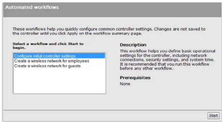
Three workflows are available:
- Configure initial controller settings: This workflow helps you to initially configure the controller by defining network connections, security settings, and system time. It is recommended that you run this workflow on factory-default controllers.
- Create a wireless network for employees: This workflow helps you create a new wireless network to provide wireless access for employees. It lets you define how employee traffic be distributed onto your wired infrastructure and configure wireless security settings to safeguard network traffic.
- Create a wireless network for guests: This workflow helps you create a new wireless network to provide wireless access for guests. It lets you define how guests will be authenticated (a RADIUS server or the local user accounts feature on the controller) and how guests will receive an IP address.
Each workflow provides instructions and prompts you for options. Read the instructions and res to the prompts as desired, selecting Next to get to subsequent workflow pages. Context-sensitive online help is also available for each workflow page.
The last step in each workflow provides a summary of all configuration settings that will be applied upon final confirmation. For example, the summary page for the Configure initial controller settings workflow looks similar to this:

Review the settings before you select Apply to save and activate your settings on the controller. Alternatively, you can select Back to go to the previous workflow page or select Cancel to discard your workflow settings and exit the workflow.
After applying your settings, a confirmation page appears showing the menu path to the configuration page for each setting that was changed by the workflow. For example:

At this point you can:
- Select a page link to make further configuration changes. When done, select Automated workflows to return to the confirmation page.
- Select Done to return to the Automated workflows home page.
[Non-Text]
TIP: See also the MSM7xx Controller Installation Guide specific to your controller model for more workflow information.
Setting up manager and operator accounts
Two types of administrative user accounts are defined on the controller: manager and operator.
•The manager account provides full management tool rights.
- The operator account provides read-only rights plus the ability to disconnect wireless clients and perform troubleshooting.
To configure the accounts, select Controller >> Management > Management tool.

Only one administrator (manager or operator) can be logged in at any given time. Options a provided to control what happens when an administrator attempts to log in while another administrator (or the same administrator in a different session) in already logged in. In every of the manager's rights supersede those of an operator.
The following options can be used to prevent the management tool from being locked by an idle manager or operator:
- Terminates the current manager session: When enabled, an active manager or operator session will be terminated by the login of another manager. This prevents the management tool from being locked by an idle session until the Account inactivity logout timeout expires.
- Is blocked until the current manager logs out: When enabled, access to the management tool is blocked until an existing manager logs out or is automatically logged out due to an idle session.
An operator session is always terminated if a manager logs in. An active operator session cannot block a manager from logging in.
- Terminates the current operator session: When enabled, an active operators session will be terminated by the login of another operator. This prevents the management tool from being locked by an idle session until the Account inactivity logout timeout expires.
Operator access to the management tool is blocked if a manager is logged in. An active manager session cannot be terminated by the login of an operator.
An operator session is always terminated if a manager logs in. An active operator session cannot block a manager from logging in.
- Login control: If login to the management tool fails five times in a row (bad username and/or password), login privileges are blocked for five minutes. Once five minutes expires, login privileges are once again enabled. However, if the next login attempt fails, privileges are again suspended for five minutes. This cycle continues until a valid login occurs. You can configure the number of failures and the timeout.
- Account inactivity logout: By default, if a connection to the management tool remains idle for more than ten minutes, the controller automatically terminates the session. You can configure the timeout.
Administrative user authentication
Login credentials can be verified using local account settings and/or an external RADIUS sever. This also affects how many accounts you can have.
- Local: Select this option to use a single manager and operator account. Configure the settings for these accounts under Manager account and Operator account.
- RADIUS: Using a RADIUS server enables you to have multiple manager and operator accounts, each with a unique login name and password. To setup this option, see "Authenticating manager logins using a third-party RADIUS server" (page 288).
If both options are enabled, the RADIUS server is always checked first.
Passwords
Passwords must be 6 to 16 printable ASCII characters in length with at least 4 different character passwords are case sensitive. Space characters and double quotes ( " ) cannot be used. Pass must also conform to the selected security policy as follows.
- Follow FIPS 140-2 guidelines: When selected, implements the following requirements from the FIPS 140-2 guidelines:
- All administrator passwords must be at least six characters long. - All administrator passwords must contain at least four different characters.
For more information on these guidelines, refer to the Federal Information Processing Standards Publication (FIPS PUB) 140-2, Security Requirements for Cryptographic Modules.
- Follow PCI DSS 1.2 guidelines: When selected, implements the following requirements from the PCI DSS 1.2 guidelines:
- All administrator passwords must be at least seven characters long.
- All administrator passwords must contain both numeric and alphabetic characters.
-
The settings under Login control must be configured as follows:
-
Lock access after nn login failures must be set to 6 or less.
- Lock access for nn minutes must be set to 30 minutes or more.
The settings under Account inactivity logout must be configured as follows:
- Timeout must be set to 15 minutes or less.
For more information on these guidelines, refer to the Payment Card Industry Data Security Standard v1.2 document.
Manager username/password reset
Not supported on the MSM-765.
The Allow password reset via console port feature provides a secure way to reset the manager login username/password on a controller to factory default values (admin/admin), without having to reset the entire controller configuration to its factory default settings. To make use of this fee you must be able to access the controller through its console (serial) port. See "Console ports" (page 465).
IMPORTANT:
- This feature is automatically enabled after performing a reset to factory default settings.
- This feature is automatically disabled after performing a software (firmware) upgrade from release 5.4x or earlier.
CAUTION: If you disable this feature and then forget the manager username or password, the only way to gain access the management tool is to reset the controller to its factory default set. See "Resetting to factory defaults" (page 467).
Configuring management tool security
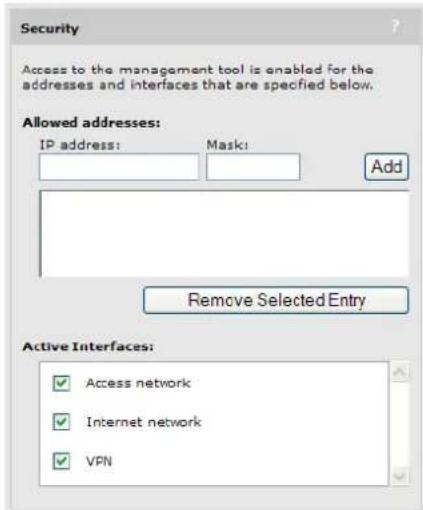
Select Controller >> Management > Management tool and configure the settings under Security. On the E-MSM720
On all other controllers

Allowed addresses
Enables you to define a list of IP address from which to permit access to the management too. To add an entry, specify the IP address and appropriate mask and select Add. When the list is empty, access is permitted from any IP address. For example: To allow access for a single computer with IP address 192.168.1.209, specify:
IP address = 192.168.1.209
Mask = 255.255.255.255
To allow access for several computers in the IP address range 192.168.10.16 to 192.168.10.31, specify:
IP address = 192.168.10.16
Mask = 255.255.255.240
Active interfaces
Select the interfaces through which access to the management tool will be permitted. (These settings also apply when SSH is used to access the command line interface.)
Configuring the Login page message
You can customize the message that is displayed at the top of the login page by selecting Controller >> Management > Management tool and entering a new message under Login message.
![Login message Login message: Authorized access only. This system is property of [COMPANY NAME].](/content/2026/05/1076986/images/518276a9d0e71a9eaf25dbd2cf41a9765f94e60e736a83da0af760e0c2b1f027.jpg)
Configuring Auto-refresh
Select Controller >> Management > Management tool and configure the settings under Auto-Refresh. This option controls how often the controller updates the information in group boxes that show auto-refresh icon in their title bar. Under Interval, specify the number of seconds between refreshes.

Setting the system time
Select Controller >> Management > System time to open the System time page. This page enables you to configure the time server and time zone information.

- Set timezone & DST as appropriate.
- Set Time server protocol, to Simple Network Time Protocol.
- Select Set date & time (time servers) and then select the desired time server. Add other servers if desired. The controller contacts the first server in the list. If the server does not reply, the controller tries the next server and so on. By default, the list contains two ntp vendor zones pools that are reserved for HP networking devices. By using these pools, you will get better service and keep from overloading the standard ntp.org server. For more information visit: www.pool.ntp.org.
- Select Save and verify that the date and time is updated accurately. A working Internet connection on Port 1 is required.
NOTE: If access to the Internet is not available to the controller, you can temporarily set the time manually with the Set date & time (manually) option. However, It is important to configure a reliable time server on the controller. Correct time is particularly important when a controller is used. Synchronization and certificate problems can occur if the time is not accurate.
3 Network configuration
Working with network profiles
The controller uses logical entities called network profiles to manage the configuration of network settings. Network profiles let you define the characteristics of a network and assign a friendly nan and VLAN to it. Once defined, network profiles can then be assigned to a port or a trunk (E-MSM720 only) as required. Network profiles make it easy to use the same settings in multiple places on the controller.
For example, if you define a network profile with a VLAN ID of 10, you could use that profile t
• Map VLAN 10 to a controller port using the Controller >> Network > VLANs page.
- Set VLAN 10 as the egress network for a group of APs when binding them to a VSC using the Controlled APs > [group] >> VSC bindings page.
- Set VLAN 10 as the local network for an AP using the Controlled APs >> Configuration > Local network page.
- Map VLAN 10 to a trunk as either tagged or untagged using the Controller >> Network > VLANs page.
About the default network profiles
Two network profiles are created by default. The names assigned to these profiles are different depending on the product you are configuring.
On the E-MSM720
The two profiles are named Access network and Internet network. You can edit these profiles, but you cannot delete them. By default, they are configured as follows:
- Access network: Assigned to VLAN 1 and is mapped to ports 1, 2, 3 4, untagged. (On an untagged port, the VLAN is only used internally to route/switch traffic.) The Access network profile can only be configured with a static IP address. By default, this address is 192.168.1
- Internet network: Assigned to VLAN 10 and is mapped to ports 5 and 6, untagged. To see the mapping, consult the VLANs page. (On an untagged port, the VLAN is only used internal to route/switch traffic.) By default, this profile is configured to operate as a DHCP client to automatically obtain an address from a DHCP server.
To see the mappings, consult the Controller >> Network > VLANs page.
On all other controllers
The two profiles are named LAN port network and Internet port network. These profiles are associated with the two physical Ethernet ports (LAN port and Internet port) on the controller. You can rename these profiles, but you cannot assign a VLAN to them or delete them.
• LAN port: Mapped to the LAN port. This profile can only be configured with a static IP address. By default, it is set to 192.168.1.1.
- Internet port: Mapped to the Internet port. By default, this profile is configured to operate as a DHCP client to automatically obtain an address from a DHCP server.
To see the mappings, consult the Controller >> Network > VLANs page.
To define a new network profile
- Select Controller >> Network > Network profiles.
On the E-MSM720

On all other controllers

- Select Add New Profile.

- Configure profile settings as follows:
• Under Settings, specify a Name for the profile.
•To assign a VLAN, select VLAN ID and then specify an number.
If needed, you can also define a range of VLANs. This enables a single VLAN definition span a large number of contiguously assigned VLANs. Specify the range in the form X-Y, where X and Y can be 1 to 4094. For example: 50-60.
An IP address cannot be assigned to a VLAN range.
You can define more than one VLAN range by using multiple profiles. Each range must be distinct and contiguous.
- Select Save.
Configuring IP interfaces
The IP interfaces page lists all network profiles to which an IPv4 address is assigned. To open IP interfaces page, select Controller >> Network > IP interfaces.
On the E-MSM720

On all other controllers

The following interfaces are created by default. They can be edited, but not deleted.
On the E-MSM720
- Access network is assigned to VLAN 1 and is mapped to ports 1, 2, 3 4, untagged. (On an untagged port, the VLAN is only used internally to route/switch traffic.)
- Internet network is assigned to VLAN 10 and is mapped to ports 5 and 6, untagged. (On an untagged port, the VLAN is only used internally to route/switch traffic.)
On all other controllers
• LAN port is assigned to the LAN port untagged.
- Internet port is assigned to the Internet port untagged.
To assign an IP address to a new interface on the E-MSM720
Any network profile that has a VLAN ID and is mapped to a physical port can have an IP addr assigned to it. The following steps illustrate how to create a new profile and assign an IP address to it.
- Select Controller >> Network > Network profiles.
- Select Add New Profile.
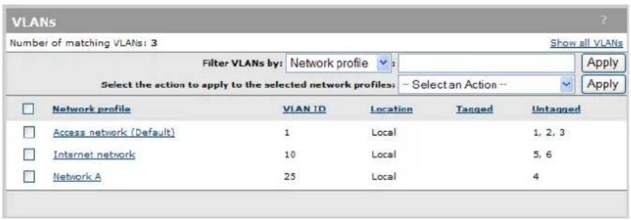
- Specify a name for the profile and assign a VLAN ID to it. This example uses the profile name Network A and a VLAN ID of 25. Select Save.

4. Select Controller >> Network > VLANs to open the VLANs page.

- Select the new profile in the table to open the Add/Edit VLAN mapping page.
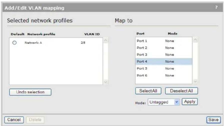
- Select the port to which you want to map the profile (in this case port 4). Next, select Untagged for Mode, then select Apply.
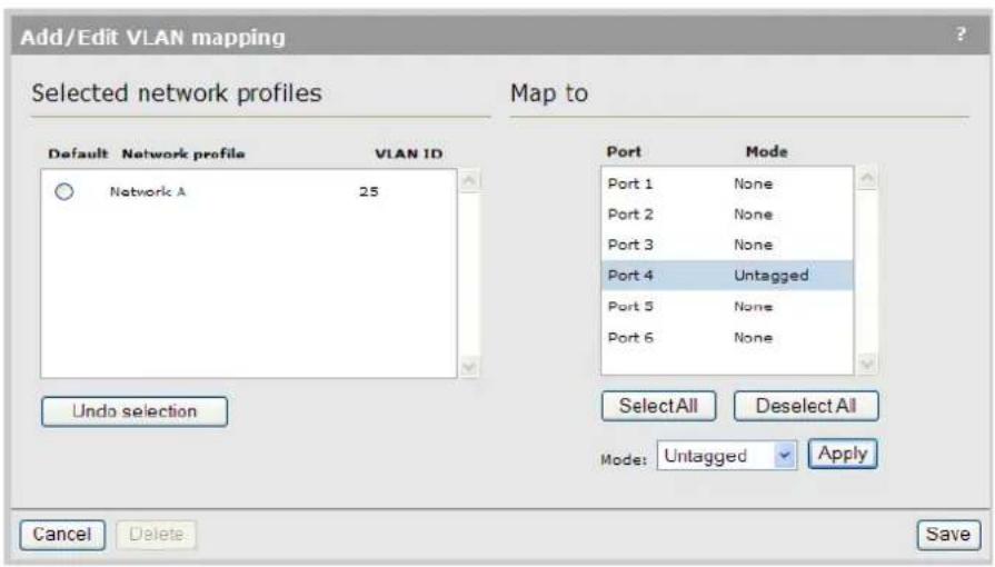
- Select Save. The profile is mapped to port 4 untagged.
- Select Controller >> Network > IP interfaces to open the IPv4 interfaces page.

- Select Add New Interface to open the Add/Edit interface page.

- Under Interface, select the network profile that you defined earlier.
- Under Assign IP address via, select the addressing method to use.
- DHCP client: Dynamic host configuration protocol. The DHCP server will automatically assign an address to the network profile, which functions as a DHCP client.
• Static: Specify an IP address, Mask, and Gateway.
- Enable/disable NAT support if required.
- Select Save. The new interface is added to the IPv4 interfaces table.

To assign an IP address to a new interface on other controllers
Any network profile that has a VLAN ID and is mapped to a physical port can have an IP addr assigned to it. The following steps illustrate how to create a new profile and assign an IP address to it.
- Select Controller >> Network > Network profiles.
-
Select Add New Profile.
-
Specify a name for the profile and assign a VLAN ID to it. This example uses the profile name Network A and a VLAN ID of 25. Select Save.

- Select Controller >> Network > VLANs to open the VLANs page.

- Select the new profile in the table to open the Add/Edit VLAN mapping page.

- Select the port to which you want to map the profile (in this case the LAN port).
- Select Save. The profile is mapped to port 4 untagged.

- Select Controller >> Network > IP interfaces to open the IPv4 interfaces page.

- Select Add New Interface to open the Add/Edit interface page.

- Under Interface, select the network profile that you defined earlier.
- Under Assign IP address via, select the addressing method to use.
- DHCP client: Dynamic host configuration protocol. The DHCP server will automatically assign an address to the network profile, which functions as a DHCP client.
• Static: Specify an IP address, Mask, and Gateway.
- Enable/disable NAT support if required.
- Select Save. The new interface is added to the IPv4 interfaces table.

Configuring the Access network/LAN port interface
The following configuration options are available if you select the Access network interface (on an E-MSM720) or LAN port interface (on all other controllers) in the table.
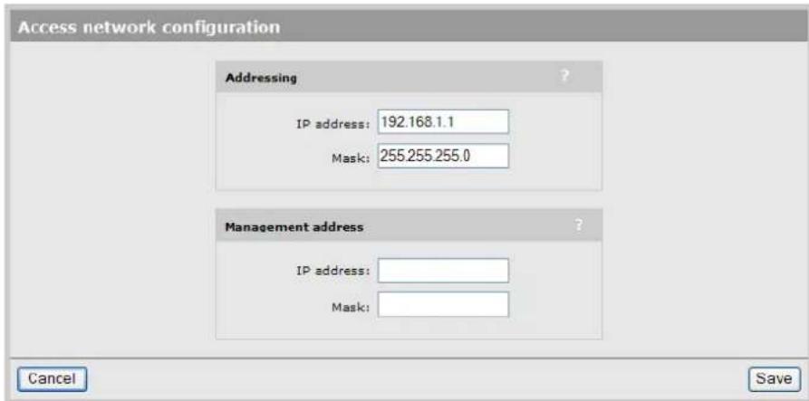
Addressing
The Access network/LAN port interface must be configured with a static IP address. By default, is set to the address 192.168.1.1.
Management address
Use this option to assign a second IP address to the Access network/LAN port interface. This address provides a simple way to separate management traffic from user traffic without using VLANs.
For example, by default the Access network/LAN port interface is set to 192.168.1.1 and all devices obtain an address on this subnet from the controller DHCP server. With this feature yo can add another address, say 192.168.2.1/255.255.255.0. APs can then be assigned to this subnet using static IP addressing. Now all management traffic exchanged between the controlle and the APs is on a separate subnet.
Configuring the Internet network/Internet port interface
The following configuration options are available if you select the Internet network interface (on an E-MSM720) or Internet port interface (on all other controllers) in the table.

By default, the Internet port operates as a DHCP client. Select the option you want to use and se Configure. Refer to the following sections for additional configuration information.
- "Configuring the PPPoE client" (page 30)
- "Configuring the DHCP client" (page 31) (default setting)
• "Static addressing" (page 32)
• No address.
Network address translation
Enable this option to permit all the computers on the network to simultaneously share the connection on the Internet port. See "Network address translation (NAT)" (page 51).
Limit NAT port range
When enabled, the controller reserves a range of TCP and UDP ports for each authenticated, access-controlled user starting at port 5000, and maps all outgoing traffic for the user within the range.
NOTE: If you enable this feature you should not assign static NAT mappings in the range 5000 to 10000.
Size of port range
Sets the number of TCP and UDP ports reserved for each user.
Configuring the PPPoE client

-
Under Settings, define the following:
-
Username: Specify the username assigned to you by your ISP. The controller will use this username to log on to your ISP when establishing a PPPoE connection.
- Password/Confirm password: Specify the password assigned to you by your ISP. The controller will use this password to log on to your ISP when establishing a PPPoE connection.
- Maximum Receive Unit (MRU): Maximum size (in bytes) of a PPPoE packet when receiving. Changes to this parameter only should be made according to the recommendations of your ISP. Incorrectly setting this parameter can reduce the throughput of your Internet connection.
- Maximum Transmit Unit (MTU): Maximum size (in bytes) of a PPPoE packet when transmitting. Changes to this parameter should only be made according to the recommendations of your ISP. Incorrectly setting this parameter can reduce the throughput of your Internet connection.
- Auto-reconnect: The controller will automatically attempt to reconnect if the connection is lost.
-
Un-numbered mode: This feature is useful when the controller is connected to the Internet and NAT is not being used. Instead of assigning two IP addresses to the controller, c to the Internet port and one to the LAN port, both ports can share a single IP addre. This is especially useful when a limited number of IP addresses are available to you.
-
Under Assigned by PPPoE server, select Restart Connection. Once you are connected to the server, the following fields will display information about your connection. The Internet connection is not active until this occurs. Refer to the online help for a description of each field.
Configuring the DHCP client

The DHCP client does not require any configuration, unless you need to set a value for the oDHCP Client ID parameter for proper operation with your DHCP server.
Once you are connected to the server, the fields under Assigned by DHCP server show the settings assigned to the controller by the DHCP server. The connection is not active until this occurs. R to the online help for a description of each field.
If you want to force the DHCP client to obtain a new lease, select Release and then Renew.
Static addressing

Under Port settings, define the following:
• IP address: Specify the static IP address you want to assign to the port.
- Address mask: Specify the appropriate mask for the IP address you specified.
- Default gateway: Specify the address of the default gateway on the network.
Additional IP addresses
You need to configure these settings if you are making use of the VPN one-to-one NAT feature of the public IP address feature. For more information see:
• "VPN one-to-one NAT" (page 435)
- "Assigning public IP addresses" (page 37)
Configuring port settings
To configure settings for the physical ports on the controller, select Controller >> Network > Ports. On the E-MSM720
| Port configuration | |||||
| Name | Duplex | Speed | Trunk type | Trunk group | MAC address |
| Port 1 | None | 78:e3:b5:8e:c0:a2 | |||
| Port 2 | None | 78:e3:b5:8e:c0:a3 | |||
| Port 3 | None | 78:e3:b5:0e:c0:a4 | |||
| Port 4 | None | 78:e3:b5:8e:c0:a5 | |||
| Port 5 | Full | 1 Gbps | None | 78:e3:b5:8e:c0:a6 | |
| Port 6 | None | 78:e3:b5:8e:c0:a7 | |||
On all other controllers

Status light
• Green: Port is properly configured and ready to send and receive data.
- Red: Port is not properly configured or is disabled.
Jack
Supported on the MSM765 only.
Indicates the jack (physical interface) to which a port is assigned.
Name
Identifies the port.
Duplex
Not supported on the MSM765.
Indicates if the port is Full or Half duplex.
Speed
Not supported on the MSM765.
Indicates the speed at which the port is operating.
Trunk type
Only supported on the E-MSM720.
Indicates the type of trunk to which the port is assigned:
•None: The port is not assigned to a trunk.
- Trunk: The port is assigned to a static trunk.
• LACP: The port is assigned to a dynamic trunk that uses LACP (active mode).
Trunk group
Only supported on the E-MSM720.
Indicates the trunk group to which a port is assigned.
- Trunk n: The port is assigned to a static trunk, with n indicating the trunk number (1 to 6).
- Dyn n: The port is assigned to a dynamic trunk (LACP), with n indicating the trunk number (1 to 6). A separate LACP trunk is automatically created for each LACP-enabled switch which the E-MSM720 is connected. For example, if you connect ports 1 and 2 to swi 1, and ports 3 and 4 to switch 2, then the controller automatically creates the groups 1 and Dyn 2.
MAC address
Indicates the MAC address of the port.
Configuring E-MSM720 ports
All E-MSM720 ports have the same configuration settings, for example, Port 1:

Trunk settings
Use these settings to map the port to a trunk group. For more information on trunking, see "Port trunking" (page 59).
Type None: The port is not assigned to a trunk group.
- LACP: The port is assigned to a dynamic trunk that uses LACP.
- Trunk: The port is assigned to a static trunk group.
Group If Type is set to Trunk, select the trunk group to which the port will be assigned.
Link settings
By default, the controller automatically adjusts link settings based on the type of equipment the port is connected to. If needed, you can force the port to operate at a particular speed or duplex setting.
Configuring the LAN/Internet port (MSM710, MSM760, MSM765zl)
Configuration settings for the LAN port and Internet port are identical, for example, the MSM760 LAN port:

Link settings
By default, the controller automatically adjusts link settings based on the type of equipment the port is connected to. If needed, you can force the port to operate at a particular speed or duplex setting.
Configuring DHCP services
The controller can operate as a DHCP server or DHCP relay agent on the LAN port. This enables it to assign IP addresses to downstream devices connected to the LAN port.
By default, address allocation is disabled. To configure address allocation settings, select Controller >> Network > Address allocation.

For information on VPN address pool, see "Configure an IPSec profile for wireless client VPN" (page 429).
Configuring the global DHCP server
The global DHCP server can be used to automatically assign IP addresses to devices that are connected to the controller via the LAN port or through the client data tunnel. If you do not have a DHCP server operating on your network, you can use the global DHCP server to assign additional to your wired clients, wireless clients, and controlled APs.
For added flexibility, separate DHCP servers can be enabled on any access-controlled VSC, enabling different address ranges to be served. For details, see "DHCP server" (page 120).
NOTE:
- Do not enable the DHCP server if the LAN port (Access network on the E-MSM720) is connected to a network that already has an operational DHCP server.
•The global DHCP server settings are always used by the default VSC.
•The DHCP server feature is not supported when controller teaming is active.
To configure the global DHCP server
- Select Controller >> Network > Address allocation.

- Select DHCP server and then Configure.

-
Under Addresses, define the following:
-
Start / End: Specify the starting and ending IP addresses that define the range of addresses the DHCP server can assign to client stations. The address assigned to the controller is automatically excluded from the range.
-
Gateway: Specify the IP address of the default gateway the controller will assign to DHCP users. In most cases you will specify the IP address of the controller LAN port as the Gateway.
• DNS servers to assign to client stations: This is always the IP address of the LAN port. -
Under Settings, define the following:
- Domain name: Specify the domain name the controller will return to DHCP users. Typically, this will be your corporate domain name.
The host name in the currently installed SSL certificate is automatically assigned as the domain name of the controller. The factory default SSL certificate that is installed on the controller has the host name wireless.hp.internal.
You do not have to add this name to your server for it to be resolved. The controller intercepts all DNS requests it receives. It resolves any request that matches the certificate host name by returning the IP address assigned to the Internet port. All other DNS requests are forwarded to the appropriate DNS servers as configured on the Controller >> Network > DNS page.
To summarize, this means that by default, any DNS request by a user that matches wireless.hp.internal will return the IP address of the LAN port (Access network on the E-MSM720).
- Lease time: Specify the lease time (in seconds) that the controller will assign to all assigned addresses. As long as a user remains connected their address is automatically renewed when the lease time expires. If a user disconnects without releasing their address, then the address remains reserved until the lease time expires. If you have a small address pool and a large user turnover, setting a long lease time may cause you to run out of addresses even though they are not really in use.
- Logout HTML user on discovery request: When enabled, the controller will log out a client station if a DHCP discovery request is received from the client station while a DHCP address lease is currently assigned.
This feature is useful when multiple users share the same client station. If a user forgets to log out before turning off the client station, the next user will have to wait until the le expires before being able to log in.
- Listen for DHCP requests on: Select the port on which the controller will listen for DHCP requests from client stations.
LAN port (Access network on the E-MSM720): Listen for requests on the LAN port (Access network on the E-MSM720).
- Client data tunnel: Enable this option when the client data tunnel feature is active on one or more VSCs, and you want tunneled client stations to be able to receive an II address from the controllers DHCP server.
- Select Save.
Assigning fixed DHCP leases
Use this feature to permanently reserve an IP addresses lease for a specific device. This ensures that the device is always reachable at the same address on the network, but does not require a static address to be set directly on the device itself. This table lists all permanently reserved addresses. Up to 255 fixed leases can be defined.
| Active fixed leases | |||
| Mac Address | Ip Address | Unique identifier | Delete |
| 00:03:52:08:02:32 | 192.168.45.30 | 00:03:52:08:02:32 | |
| 00:03:52:08:03:14 | 192.168.45.31 | 00:03:52:08:03:14 | Add |
To assign a specific IP address to a client station specify the following and select Add:
• MAC address: MAC address of the client station in the format: nn:nn:nn:nn:nn:nn.
• IP address: IP address that will be assigned to the client station in the format: nnn.nnn.nnn.nnn.
- Unique identifier: A number that identifies the device. Must be unique to all DHCP clients on the network. Generally set to the MAC address of the client station. This parameter is opt unless MAC masquerading is being performed by the client station.
Assigning public IP addresses
This feature enables the integrated DHCP server on the controller to assign public IP addresses users. A user with a public IP address is visible on the protected network connected to the Internet port, instead of being hidden by the controllers NAT feature. This makes it possible for external devices to create connections with a users computer on the internal network.
Public IP addresses are assigned by the integrated DHCP server using the addresses specified the Address pool. Whenever possible, this feature will assign the same public IP address to a user each time they connect.
When you enable public IP address support in a subscription plan, an additional setting is available called Reserve public IP address. When this option is enabled, the public IP assigned to a user is reserved until the users subscription plan expires. This means that the address is reserved, ever the user is not logged in.
When a public IP address is assigned to a user:
•The user cannot access any VLANs, VPNs, or GRE tunnels configured on the controller.
•The user cannot establish more than one concurrent session.
NOTE: If a users account is configured for public IP address support and there is no free public IP address in the pool when the user tries to login, the login is refused.
Assigning public IP addresses to users
To obtain a public IP address, a users account must have its Public IP address option enabled. Do this as follows:
- If using the local user accounts (defined on the Controller >> Users menu), enable the Public IP address option in the account profile or subscription plan that is assigned to the user. "Defining account profiles" (page 277) and "Defining subscription plans" (page 278).
- If using Active Directory, enable the Public IP address option in the account profile (see "Defining account profiles" (page 277)) that is assigned to an Active Directory group. To up an Active Directory group, see "Configuring an Active Directory group" (page 291).
- If using a RADIUS server, add the following Colubris AV-Pair value to the users account: use-public-ip-subnet=1. For more information, see "Default user public IP address" (page 395) and "Default user public IP address" (page 395).
DHCP server lease time
Use this setting to define the amount of time the public IP address lease will be valid. This se only applies to public IP addresses. It overrides the DHCP lease time set by selecting Controller >> Network > Address allocation > DHCP server.
Address pool
The address pool contains all the public IP addresses that can be assigned to users. You can def up to 30 addresses.
Addresses must be valid for the network to which the Internet port is connected. Specify a single address or an address range as follows: address1 - address2. For example, the following defines a range of 20 addresses: 192.168.1.1-192.168.1.20
Configuring the DHCP relay agent
The controller provides a flexible DHCP relay implementation. It can listen for requests on the LAN port or client data tunnel and forward them to a DHCP via any of the controllers physical or log interfaces.
For additional flexibility, separate DHCP relay agents can be enabled on access-controlled VSCs. See "DHCP relay agent" (page 120).
NOTE:
- DHCP relay is not supported on the Internet port when it is operating as a PPPoE client or if the firewall is set to High and NAT is enabled. This is because DHCP server must be able to ping the assigned address to prevent duplicate assignments.
IMPORTANT: You must define routes on the DHCP server, so that the DHCP server can successfully send DHCP response packets back to the DHCP relay agent on the controller. These should be static and persistent host routes that identify the IP address assigned to the controller LAN port or additional VSC relay IP address, (i.e. 192.168.1.1). On Windows, such a static route would look like this:
route add 192.168.1.1 mask 255.255.255.255 10.10.10.22 metric 1 p
To configure the global DHCP relay agent
-
Select Controller >> Network > Address allocation.
-
Select DHCP relay agent, and then Configure.

- Under Settings, define the following:
- Under Listen for requests on, select the interface on which the DHCP relay agent will listen for requests. Enable Client data tunnel option when the client data tunnel feature is active on one or more VSCs, and you want tunneled users to be able to receive an IP address via the DHCP relay agent. See Client data tunnel.
The following two fields let you attach information to the DHCP request (as defined by DHCP relay agent information option 82) which lets the DHCP server identify the controller.
- Circuit ID: Use this field to identify the user that issued the DHCP request.
- Remote ID: Use this field to identify the controller.
You can use regular text in combination with the following placeholders to create the information in each field. Placeholders are automatically expanded when the request is sent. The following placeholders can be used:
- %S:SSID to which the user is associated.
•%B:BSSID to which the user is associated.
•%v:VLAN to which the user is mapped.
4. Under Server, define the following:
- Primary DHCP server address: Specify the IP address of the first DHCP server to which the controller should forward DHCP requests.
- Secondary DHCP server address: Specify the IP address of the backup DHCP server to which the controller should forward DHCP requests.
- Extend VSC egress subnet to VSC ingress subnet: Enable this option to have the controller alter the DHCP address requests from client stations so that they appear to originate from the network assigned to the VSC egress. This will cause the DHCP server to assign IP addresses on this network to all client stations. The controller handles all mapping between the two subnets internally.
For L2 connected APs operating in controlled mode:
- Enable the Client data tunnel option under Settings. (If teaming is active, the client data tunnel is automatically used.)
- Enable the Always tunnel client traffic option on the VSC profile page under Virtual AP > Client data tunnel.
5. Select Save.
Configuring GRE tunnels
To view and configure GRE tunnel definitions, select Controller >> Network > GRE tunnels. Initially, no GRE tunnels are defined.

To add a tunnel, select Add New GRE Tunnel. The Add/Edit GRE tunnel page opens.
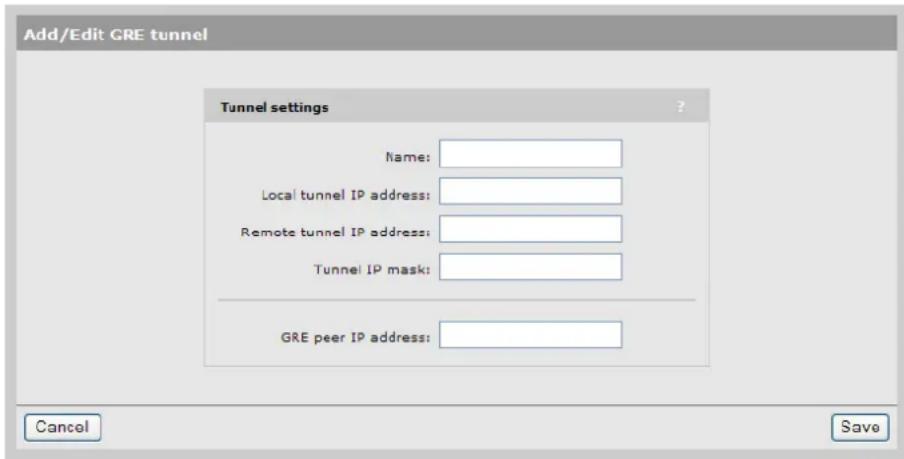
Define tunnel settings as follows:
Name
Tunnel name.
Local tunnel IP address
Specify the IP address of the controller inside the tunnel.
Remote tunnel IP address
Specify the IP address of the remote device inside the tunnel.
Tunnel IP mask
Specify the mask associated with the IP addresses inside the tunnel.
GRE peer IP address
Specify the IP address of the remote device that terminates the tunnel.
Bandwidth control
The controller incorporates a bandwidth management feature that enables control of all user traffic flowing through the controller.
To configure bandwidth control, select Controller >> Network > Bandwidth control.

Bandwidth control has two separate components: Data rate limits and bandwidth levels. They interact with the data stream as follows:
![graph LR A["Traffic from the site access list"] --> B["User traffic"] C["Management traffic"] --> D["User Data Rate Limits"] E["User traffic"] --> D D --> F["Level"] F --> G["Very High"] F --> H["High"] F --> I["Normal"] F --> J["Low"] G --> K["Internet Port Data Rate Limit"] H --> K I --> K J --> K…](/content/2026/05/1076986/images/19f24447411a41819625a479bfe4deb93a1d4bda6b76304f309f8e46d425edd6.jpg)
Data rate limits
These settings enable you to limit the total incoming or outgoing data rate on the Internet network profile (E-MSM720) or Internet port (all other controllers). If traffic exceeds the rate you set for bursts, it is buffered. Long overages will result in data being dropped.
To utilize the full available bandwidth, the Maximum transmit rate and Maximum receive rate should be set to match the incoming and outgoing data rates supported by the connection established on the Internet port.
Bandwidth levels
The controller provides four levels of traffic priority that you can use to manage traffic flow: Very High, High, Normal, and Low. The settings for each level are customizable, allowing performance to be tailored to meet a wide variety of scenarios.
Assigning traffic to a bandwidth level
Traffic can be assigned to a specific bandwidth level for each VSC and for each user. For ba control to be operational, you must first enable the Data rate limits option. Once this is done, you can assign traffic to bandwidth levels as follows:
- In a VSC, select the default level for all user traffic in the Bandwidth control box. This level applies to users who do not have a specific assignment in their user account.

• In a users account profile, set the Bandwidth level in the Bandwidth limits box.

- Or if you are using a RADIUS server to validate user logins, set the bandwidth level using a Colubris AV-Pair value. See "Bandwidth level" (page 405).
To control the default bandwidth level for all users, see "Default user bandwidth level" (page 393).
NOTE:
- Management traffic (which includes RADIUS, SNMP, and administrative sessions) is assigned to bandwidth level Very High and cannot be changed.
- All traffic assigned to a particular bandwidth level shares the allocated bandwidth for that level across all VSCs. This means that if you have three VSCs all assigning user traffic to High all users share the bandwidth allocated to the High level.
Customizing bandwidth levels
Bandwidth levels are arranged in order of priority from Very High to Low. Priority determines how free bandwidth is allocated once the minimum rate is met for each level. Free bandwidth is always assigned to the higher priority levels first.
Bandwidth rates for each level are defined by taking a percentage of the maximum transmit and receive rates defined for the Internet port. Each bandwidth level has four rate settings:
- Transmit rate - guaranteed minimum: Minimum amount of bandwidth that will be assigned to a level as soon as outgoing traffic is present on the level.
- Transmit rate - maximum: Maximum amount of outgoing bandwidth that can be consumed by the level. Traffic in excess is buffered for short bursts, and dropped for sustained overages
- Receive rate - guaranteed minimum: Minimum amount of bandwidth that will be assigned to a level as soon as incoming traffic is present on the level.
- Receive rate - maximum: Maximum amount of incoming bandwidth that can be consumed by the level. Traffic in excess is buffered for short bursts, and dropped for sustained overages.
Example
For example, assume that transmit bandwidth is configured as follows:
| Transmit rates | ||
| MaxMin | ||
| 2020Very High | ||
| 10040High | ||
| Normal | 10020 | |
| 2020Low | ||
Next, assume the following bandwidth requirement occurs on transmitted user data:
•High requires 70%, which is 30% more than its minimum.
•Normal requires 50%, which is 30% more than its minimum.
- There is no traffic on Very High or Low.
Since both High and Normal require bandwidth in excess of their guaranteed minimum, each is allocated their guaranteed minimum. This leaves 40% of the bandwidth free to be assigned on a priority basis. High has more priority than Normal, so it takes as much bandwidth as needed. In this case it is 30%, which brings High up to 70%. This leaves 10% for Normal, which is not en Traffic is buffered for a short period, and then dropped.
If at the same time Very High traffic is sent, this level immediately steals 20% from the lower level. In this case, 10% is taken from Normal, returning it to its minimum guaranteed level, and 10% is taken from High.
Discovery protocols
The controller supports two protocols (LLDP and CDP) that provide a mechanism for devices on network to exchange information with their neighbors.
To configure these protocols, select Controller >> Network > Discovery protocols.
On the E-MSM720

On all other controllers

CDP configuration
The controller can be configured to transmit CDP (Cisco Discovery Protocol) information on the LAN and Internet ports. This information is used to advertise controller information to third-party devices, such as CDP-aware switches. Network managers can retrieve this information allowing them to determine the switch ports to which different controllers are connected.
The controller always listens for CDP information on the LAN and Internet ports, even when this option is disabled, to build a list of autonomous APs. CDP information from third-party devices and controlled APs is ignored.
NOTE: Controlled APs always send CDP information.
LLDP configuration
The IEEE 802.1AB Link Layer Discovery Protocol (LLDP) provides a standards-based method for network devices to discover each other and exchange information about their capabilities. An LLDP device advertises itself to adjacent (neighbor) devices by transmitting LLDP data packets on all ports on which outbound LLDP is enabled, and reading LLDP advertisements from neighbor devices on ports that are inbound LLDP-enabled. An LLDP enabled port receiving LLDP packets inbound from neighbor devices stores the packet data in a Neighbor database (MIB).
LLDP information is used by network management tools to create accurate physical network topologies by determining which devices are neighbors and through which ports they connect.
LLDP operates at layer 2 and requires an LLDP agent to be active on each network interface that will send and receive LLDP advertisements. LLDP advertisements can contain a variable number of TLV (type, length, value) information elements. Each TLV describes a single attribute of a device.
When an LLDP agent receives information from another device, it stores it locally in a special LLD MIB (management information base). This information can then be queried by other devices via SNMP.
Support is provided for the following MIBs:
•Physical topology MIB (RFC 2922)
•Entity MIB version 2 (RFC 2737)
•Interfaces MIB (RFC 2863)
NOTE: LLDP information is only sent/received on Ethernet links. LLDP information is not collected from wireless devices connected to an AP. However, LLDP can function across a local mesh link and will show the AP on the other side of the link as a neighbor.
NOTE: When operating in controlled mode the LLDP agents on controlled APs cannot be queried via SNMP. Instead, all LLDP information from the APs is stored in the controller's MIBs.
LLDP agents
Select this option to globally activate LLDP support on the controller.
For each port, select whether the agent will transmit and/or receive LLDP information. Select
Configure TLVs to customize TLV support for each interface.
Transmit
Enable this option to have the agent transmit LLDP information to its neighbors.
Receive
Enable this option to have the agent accept LLDP information from its neighbors.
LLDP settings
Use these options to define global LLDP settings.
Transmit interval
Sets the interval (in seconds) at which local LLDP information is updated and TLVs are sent to neighboring network devices.
Multiplier
The value of Multiplier is multiplied by the Transmit interval to define the length of Time to live.
Time to live
Indicates the length of time that neighbors will consider LLDP information sent by this age to be valid. Time to live is automatically calculated by multiplying Transmit interval by Multiplier.
Generate dynamic system names
When enabled, this feature replaces the system name with a dynamically generated value which you can define.
Controller name Specify how the dynamically generated name will be created.
You can use regular text in combination with placeholders to create the name. Placeholders are automatically expanded each time the name is regenerated.
If the placeholders cause the generated name to exceed 32 characters, it is truncated.
Placeholders
- %RN: System name of the neighboring device to which the port is connected, obtained via the System Name TLV. Since this is an optional TLV, if it is not available, the ID TLV is used instead.
- %RP: Port description of the port on the neighboring device to which the local port is connected, obtained via the Port Description TLV. Since this is an optional TLV, if it not available, the Port ID TLV is used instead.
- %SN: Controller name suffix (if specified). Up to 16 characters can be appended to the name. To define the suffix for APs, select Configuration > LLDP.
%IP: Controller's IP address. An IP address can require up to 15 characters (nnn.nnn.nnn.nnn).
To create the system name, the items are concatenated using a hyphen as separator. For example:
systemname-portid-suffix
NOTE:
- Once AP names are dynamically changed by this feature, there is no way to return to the old AP names.
- When the LLDP agent is active on both the LAN port (Access Network on the E-MSM720) and the Internet port (Internet Network on the E-MSM720), the name generated on the LAN port is used for both interfaces..
- The dynamic name on the controller is only updated when a change is detected in the neighbor to which a port is connected.
- Once AP names are dynamically changed by this feature, there is no way to return to the old AP names.
• To define the suffix for APs, select Controlled APs >> Configuration > LLDP.
TLV settings
To customize TLV settings, select Configure TLVs on the Network > Discovery protocols page.

Basic TLVs
The AP supports all mandatory and optional TLVs (type, length, value) information elements that are part of the basic management set.
Mandatory TLVs
The AP always sends these TLVs with the values as shown.
Chassis ID
(Type 1): The MAC address of the AP.
Port ID
(Type 2): The MAC address of the port on which the TLV will be transmitted.
Time to live
(Type 3): Defines the length of time that neighbors will consider LLDP information sent by this agent to be valid. Calculated by multiplying Transmit interval by the Multiplier (as defined on the Discovery protocols page).
Optional TLVs
Select the optional TLVs that you want to send with the values as shown.
Port description
(Type 4): A description of the port.
System name
(Type 5): Administrative name assigned to the device from which the TLV was transmitted. By default this is the SNMP system name. If the Dynamic system name option is enabled, the system name is replaced by the dynamically generated name. The controller can only have one system name. If both the LAN and Internet ports have active agents, the name generated by the LAN port is used.
System description
(Type 6): Description of the system, comprised of the following information: operational mode, hardware type, hardware revision, and firmware version.
System capabilities
(Type 7): Indicates the primary function of the device. Set to:
WLAN access point
for APs
Router
for controllers.
Management IP address
(Type 8): Specify the IP address on which the agent will respond to management requests.
802.3 TLVs
The IEEE 802.3 organizationally specific TLV set is optional for all LLDP implementations. The AP supports a single optional TLV from the 802.3 definition.
MAC/PHY configuration/status
This TLV provides the following information:
- Bit-rate and duplex capability
•Current duplex and bit-rating
- Whether these settings were the result of auto-negotiation during link initiation or manual override.
DNS configuration
The controller provides several options to customize DNS handling. To configure these options, select Controller >> Network >DNS. The configuration options on this page change depending on the address option that is active on the Internet port.
When the Internet port (Internet network on the E-MSM720) is configured to obtain an IP addr via PPPoE or DHCP:
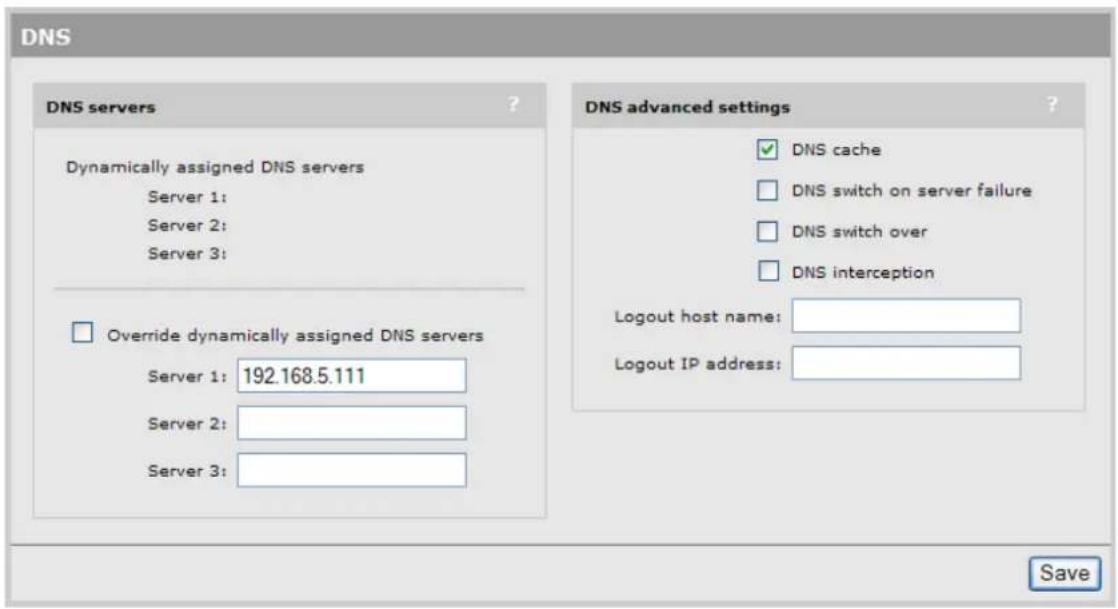
When the Internet port (Internet network on the E-MSM720) is configured to use a static IP ac
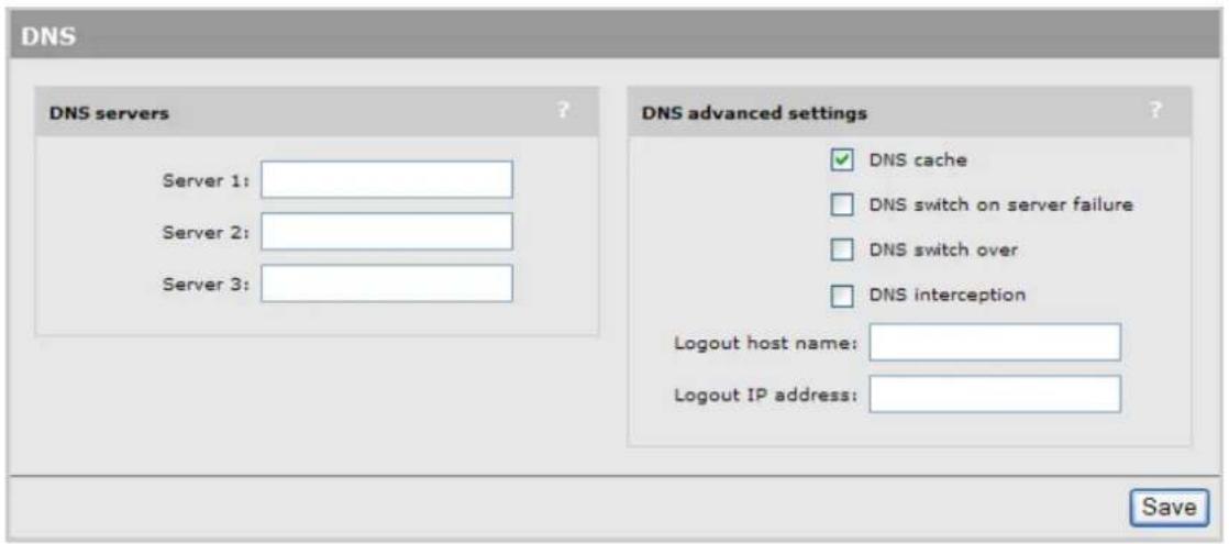
NOTE: When using Active Directory for user authentication, set the DNS servers to be the Active Directory servers or the devices that provide SRV records.
DNS servers
Dynamically assigned servers
Shows the DNS servers that are dynamically assigned to the controller when PPPoE or DHCP is used to obtain an IP address on the Internet port.
Override dynamically assigned DNS servers
Enable this checkbox to use the DNS servers that you specify on this page to replace those that are assigned to the controller.
Server 1
Specify the IP address of the primary DNS server for the controller to use.
Server 2
Specify the IP address of the secondary DNS server for the controller to use.
Server 3
Specify the IP address of the tertiary DNS server for the controller to use.
DNS advanced settings
DNS cache
Enable this checkbox to activate the DNS cache. Once a host name is successfully resolved to an IP address by a remote DNS server, it is stored in the cache. This speeds up network performance because the remote DNS server does not have to be queried for subsequent requests for this host. An entry stays in the cache until one of the following is true:
- An error occurs when connecting to the remote host.
•The time to live (TTL) of the DNS request expires.
•The controller restarts.
DNS switch on server failure
Controls how the controller switches between servers:
- When enabled, the controller switches servers if the current server replies with a DNS server failure message.
- When disabled, the controller switches servers if the current server does not reply to a DNS request.
DNS switch over
Controls how the controller switches back to the primary server.
- When enabled, the controller switches back to the primary server once the primary server becomes available again.
- When disabled, the controller switches back to the primary server only when the secondary server becomes unavailable.
DNS interception
When enabled, the controller intercepts all DNS requests and relays them to the configured DN servers. DNS interception must be enabled to support:
- Redirection of users to the public access interface login page when the controller cannot resolve the domain requested by the user. For example, if the user is using a private or local do as the default home page in its browser.
- Users with static IP addresses when the Allow any IP address option is enabled on the Controller >> Public access > Access control page.
When disabled, the controller does not intercept any DNS requests, enabling devices to use a DNS server other than the controller. To support this option, you must set Controller >>Network > Address allocation to DHCP relay agent or Static.
NOTE: When Controller >> Network > Address allocation is set to DHCP Server the controller always returns its own address as the DNS server.
Defining IP routes
The routing module on the controller provides the following features:
•Compliance with RFC 1812, except for multicast routing
•Supports Classless Inter Domain Routing (CIDR)
•Supports Routing Internet Protocol (RIP) versions 1 and 2 in active or passive mode.
Output from the router is sent to the appropriate logical interface based on the target address the traffic. Supported logical interfaces include:
• VLAN
• Untagged
- IPSec client
•PPTP client
•GRE tunnel
Configuring IP routes
To view and configure IP routes, select Controller >> Network > IP routes.
On the E-MSM720

On all other controllers

Active routes
This table shows all active routes on the controller. You can add routes by specifying the appropriate parameters and then selecting Add.
The routing table is dynamic and is updated as needed. This means that during normal operation the controller adds routes to the table as required. You cannot delete these system routes.
The following information is shown for each active route:
- Interface: The port through which traffic is routed. When you add a route, the controller automatically determines the interface to be used based on the Gateway address.
- Destination: Traffic addressed to this IP address or subnet is routed.
• Mask: Number of bits in the destination address that are checked for a match. - Gateway: IP address of the gateway to which the controller forwards routed traffic (known as the next hop).
An asterisk is used by system routes to indicate a directly connected network.
Routes cannot be manually specified for IPSec. These routes are automatically added by the system based on the settings for the IPSec security association.
- Metric: Priority of a route. If two routes exist for a destination address, the controller chooses the one with the lower metric.
- Delete: Select the garbage can icon to delete a route. If the icon has a red line through it, then the route cannot be deleted.
Default routes
The Default routes table shows all default routes on the controller. Default routes are used when traffic does not match any route in the Active routes table. You can add routes by specifying the appropriate parameters and then selecting Add.
The routing table is dynamic and is updated as needed. If more than one default route exists, the first route in the table is used.
The following information is shown for each default route:
- Interface: The port through which traffic is routed. When you add a route, the controller automatically determines the interface to be used based on the Gateway address.
- Gateway: IP address of the gateway to which the controller forwards routed traffic (known as the next hop).
An asterisk is used by system routes to indicate a directly connected network.
- Metric: Priority of a route. If two routes exist for a destination address, the controller chooses the one with the lower metric.
- Delete: Select the garbage can icon to delete a route. If the icon has a red line through it, then the route cannot be deleted.
Persistent routes
Persistent routes are automatically deleted and then restored each time the interface they are associated with is closed and opened. When the routes are active, they also appear in the A routes table.
PPTP client
The controller provides an Auto-route discovery option to enable it to automatically discover and add routes for IP addresses on the other side of a Point-to-Point Tunnelling Protocol (PPTP) tunn. The addresses must be part of the remote domain as specified on the Controller >> VPN > PPTP client page. Routes are added only when an attempt is made to access the target addresses.
Settings
About PPTP client routes (Internet port)
If you disabled the Auto-route discovery option (VPN > PPTP client), or if you need to access
IP addresses that are not part of the specified domain, you must define the appropriate per routes.
About PPTP server routes (Internet port)
Activation of the route can be triggered by a specific username. When a user establishes connection with the controller PPTP server, its username is checked against the persistent route list and if a match is found, the route is enabled.
Network address translation (NAT)
Network address translation is an address mapping service that enables one set of IP addresses to be used on an internal network, and a second set to be used on an external network. NA handles the mapping between the two sets of addresses.
Generally NAT is used to map all addresses on an internal network to a single address for u an external network like the Internet. The main benefits are that NAT:
- Enables several devices to share a single connection
- Effectively hides the IP addresses of all devices on the internal network from the external network.
This is illustrated as follows:
![graph TD A["Web Page"] -->|addressed to 192.168.1.2| B["Controller"] C["AP"] -->|HTTP request| B D["Computer"] -->|192.168.1.2| B E["Computer"] -->|192.168.1.3| B B -->|202.125.11.26| F["ISP"] F --> G["Internet"] G --> H["Web server"] H --> I["web page"] I --> J["NAT"] style B fill:#ccc,stroke:#333…](/content/2026/05/1076986/images/d234b6f0499ad239db2c6aaa2c2ccb94255c1eb9256420a7824179180b705b18.jpg)
Internal addresses are invisible to computers on the Internet.
NAT can be useful in conjunction with virtual private network (VPN) connections. When two networks are connected through a VPN tunnel, it may be desirable to obscure the address of local computers for security reasons.
NAT security and static mappings
One of the benefits of NAT is that it effectively hides the IP addresses of all devices on the inter network an external network. In some cases, however, it is useful to make a computer on the inter network accessible externally. For example, a Web server or FTP server.
Static NAT mapping addresses this problem. Static NAT mapping enables you to route specific incoming traffic to an IP address on the internal network. For example, to support a Web server, you can define a static NAT mapping to route traffic on TCP port 80 to an internal computer run a Web server.
A static NAT mapping allows only one internal IP address to act as the destination for a particular protocol (unless you map the protocol to a nonstandard port). For example, you can run only one Web server on the internal network.
NOTE:
- If you use a NAT static mapping to enable a secure (HTTPS) Web server on the internal network on TCP port 443, remote access to the management tool is no longer possible, as all incoming HTTPS requests are routed to the internal Web server and not to the management tool. You can change the default management port (TCP 443) to an alternate unused TCP port in this case.
- If you create a static mapping, the firewall is automatically opened to accept the traffic. However, this firewall rule is not visible on the Firewall configuration page (it is maintained internally by the controller).
Common applications are affected by NAT as follows:
| NATAplication | |
| Requires a static mapping to function.FTP (passive mode) | |
| Requires a static mapping to function.FTP (active mode) | |
| Requires a static mapping to function.NetMeeting | |
| Requires a static mapping to function.Telnet | |
| No effectWindows networking |
The controller provides pre-configured static mappings for most common applications, which you can enable as needed.
Most Web browsers use FTP in active mode. Some browsers provide a configuration option that enables you to alter this. Use the following steps to change this behavior in Microsoft Internet Explorer.
-
Select Tools > Internet options to open the Internet options dialog.
-
Select the Advanced tab.
-
Under Browsing, enable the Use Passive FTP for compatibility with some firewalls and DSL modems checkbox.
NAT example
The following example shows you how to configure static NAT mappings to run a Web server an FTP server on the internal network. This scenario might occur if you use the controller in a enterprise environment.
![graph TD A["Web server 192.168.1.2"] -->|Web (HTTP) traffic| B["AP"] C["FTP server 192.168.1.3"] -->|FTP traffic| D["Controller"] D -->|202.125.11.26| E["Internet"] F["Web browser"] --> E G["FTP client"] --> E B --> E D --> E E --> F style B fill:#f9f,stroke:#333 style E fill:#ccf,stroke:#333](/content/2026/05/1076986/images/9325f3b2002a11dc3474024f79db47e6a3932d11faf76490903449acb1e06048.jpg)
By creating static NAT mappings, FTP and HTTP (Web) traffic can be routed to the proper use. Note that the addresses of these stations are still not visible externally. Remote computers send their requests to 202.125.11.26, and the controller routes them to the proper client.
Use the following steps to configure the controller to support this example:
-
Select Controller >> Network > NAT > Add New Static NAT Mapping.
-
On the NAT mappings page, select Add New Static NAT Mapping.
-
Under Requests for, select Standard Services, and then select http (TCP 80).
-
Under Translate to, specify the IP address of the Web server, for example 192.168.1.2. The Settings box should now look similar to this:

-
Select Add to save your changes and return to the NAT mappings page. The new mapping is added to the table.
-
To support the FTP server, create two additional mappings with the following values:
-
Set Standard Services to ftp-data (TCP 20) and set IP address to 192.168.1.3.
- Set Standard Services to ftp-control (TCP 21) and set IP address to 192.168.1.3.
The NAT mappings table should now show all three mappings:

VPN One-to-one NAT
This feature can only be used with authenticated, access-controlled users. It is only supported when a static IP address is assigned to the Internet network on the E-MSM720, or the Internet port on other controllers. See "VPN one-to-one NAT" (page 435).
IP QoS
To ensure that critical applications have access to the required amount of wireless bandwidth, you can classify packets destined for the wireless interface into priority queues based on a number of criteria. For example, you can use any of the following to place data packets in one of four price queues for transmission onto the wireless interface:
•TCP source port
• UDP source port
- Destination port
- Port ranges
You configure IP quality of service (QoS) by creating IP QoS profiles that you can then associate with VSCs or use for global wireless settings. You can configure as many as 32 IP QoS profiles on the controller. You can associate as many as 10 IP QoS profiles with each VSC.
Configuring IP QoS profiles
To view and configure IP QoS profiles, select Controller >>Network > IP QoS. Initially, no profiles are defined.
| IP QoS profiles | ||||
| Name | Protocol | Start port | End port | Priority |
| SNMP | 6 (TCP) | 161 (SNMP) | 161 | High |
| Web | 6 (TCP) | 80 (http) | 80 | Low |
| Add New Profile... | ||||
To create an IP QoS profile, select Add New Profile.

Settings
- Profile name: Specify a unique name to identify the profile.
- Protocol: Specify an IP protocol to use to classify traffic by specifying its Internet Assigned Numbers Authority (IANA) protocol number. Protocol numbers are pre-defined for a number of common protocols. If the protocol you require does not appear in the list, select Other specify the appropriate number manually. You can find IANA-assigned protocol numbers or the Internet.
- Start port/ End port: Optionally specify the first and last port numbers in the range of ports to which this IP QoS profile applies. To specify a single port, specify the same port numb for both Start port and End port. Port numbers are pre-defined for a number of common protocols. If the protocol you require does not appear in the list, select Other and specify the appropriate number manually.
NOTE: To accept traffic on all ports for a specified protocol, set Start port to Other and 0. Also set End port to 65535.
- Priority: Select the priority level that will be assigned to traffic that meets the criteria specified in this IP QoS profile.
NOTE: It is strongly recommended that you reserve Very high priority for voice applications.
Example
This example shows how to create two IP QoS profiles and associated them with a VSC. The profiles are:
•Voice: Provides voice traffic with high priority.
•Web: Provides HTTP traffic with low priority.
Create the profiles
- Select Controller >>Network > IP QoS, and then Add New Profile. The IP QoS Profile page opens.
- Under Profile name, specify Voice.
- Under Protocol, from the drop-down list select TCP.
- Under Start port, from the drop-down list select SIP. Start port and End port are automatically populated with the correct value: 5060.
- Under Priority, from the drop-down list select Very High.

6. Select Save.
NOTE: You could also create another profile using the same parameters but for UDP to cope with any kind of SIP traffic.
- On the IP QoS Profile page select Add New Profile.
- Under Profile name, specify Web.
- Under Protocol, from the drop-down list select TCP.
- Under Start port, from the drop-down list select http. Start port and End port are automatically populated with the common HTTP port, 80.
- Under Priority, from the drop-down list select Low.

12. Select Save.
Assign the profiles to a VSC
- In the Network Tree, select VSCs, and then select one of the VSC profiles in the Name column. Scroll down to the Quality of service section in the Virtual AP box.

- Under Quality of service, set Priority mechanism to IP QoS.
- In IP QoS profiles, Ctrl-click each profile.
- Select Save.
Customizing DiffServ DSCP mappings
(These settings do not apply to IP QoS.)
You can create custom DSCP mappings that let you override the standard DSCP mappings that are defined by default when you enable DiffServ as the QoS priority mechanism for a VSC of local mesh links. This enables you to customize how traffic is assigned to the QoS priority quo To view and configure DSCP mappings, select Controller >>Network > IP QoS. Initially, no mappings are defined.

DSCP tag DSCP codepoint value.
Priority Indicates the priority level assigned to traffic that matches the DSCP tag.
- Background: Assigns the traffic to queue 4 (Lowest priority).
- Best effort: Assigns the traffic to queue 3.
•Video: Assigns the traffic to queue 2. - Voice: Assigns the traffic to queue 1 (Highest priority).
To create a new mapping
Specify a value for DSCP tag, select a Priority, and then select Add.

IGMP proxy
This feature provides support for multicast routing using IGMP (Internet Group Management Protocol) which is typically required by the controller. When enabled, the controller:
- Routes all multicast traffic received on the Upstream interface to the Downstream interface.
- Listens for IGMP host membership reports from authenticated users on the Downstream interface and forwards them to the Upstream interface. IGMP host membership reports from unauthenticated users are ignored.
NOTE:
• An access list definition must be created to accept the multicast traffic (video streams, etc.).
- Due to the nature of multicast traffic, once a user registers for a stream it automatically becomes visible to unauthenticated users as well. However, unauthenticated users are not able to reg with the IGMP group.
To view and configure IGMP proxy settings, select Controller >> Network > IGMP proxy.
On the E-MSM720

On all other controllers

4 Port trunking
Port trunking enables the E-MSM720 to combine multiple physical links into a single logical lin (trunk) to provide redundancy in the case of link failure.
The E-MSM720 supports static trunking, and dynamic trunking using the LACP (Link Aggregation Control Protocol).
Possible applications for trunking include:
- Creating a high-availability trunk to send egress traffic from the controller to a network: In this example, a static trunk is created using ports 5 and 6 to send all traffic from APs lo on different networks onto a private network. The trunk has two links, providing redundancy in the case of link failure.
![graph TD A["Private network"] --> B["Static trunk using ports 5 and 6"] B --> C["E-MSM720"] C --> D["Ports 1"] C --> E["Ports 2"] C --> F["Ports 3"] C --> G["Ports 4"] C --> H["Ports 1"] C --> I["Ports 2"] C --> J["Ports 3"] C --> K["Ports 4"]](/content/2026/05/1076986/images/228dc39a76fdd5a2877b1418249d29db31848c670a0cf0e2ada122c0321f58e2.jpg)
- Creating a high-availability trunk to tunnel traffic from wireless client stations to the controller: In this example, a dynamic trunk is created between the switch and the controller to console all traffic from the controlled APs. The trunk has six links, providing redundancy in the case of link failure. (Only two links can be active at any given time. The remainder act as ba
![graph TD A["E-MSM720"] --> B["Switch"] B --> C["Private network"] B --> D["Wireless APs"] B --> E["Dynamic Trunk with 2 to 6 links"] B --> F["Wireless APs"]](/content/2026/05/1076986/images/8862f609d5ca7df2668474790f33838604f5d0bee417a9c3d3aec9950e64d51f.jpg)
- Creating multiple trunks for traffic aggregation and routing: This example shows two trunks being used to aggregate traffic from APs, while a third trunk is used to egress traffic onto the private network.
![graph TD A["Private network"] --> B["E-MSM720"] B --> C1["Switch"] B --> C2["Switch"] B --> C3["Switch"] C1 --> D1["Wireless APs"] C2 --> D2["Wireless APs"] C3 --> D3["Wireless APs"] style A fill:#f9f,stroke:#333 style B fill:#ccf,stroke:#333 style C1 fill:#cfc,stroke:#333 style C2 fill:#cfc,stroke:…](/content/2026/05/1076986/images/c1c5aae57e22da46d1305b64a08ddf67af1af0d88aeaa46f7f092672a01859a2.jpg)
Deployment considerations
- All port trunk links must be point-to-point connections between the E-MSM720 and the other device configured for port trunking (switch, router, server, etc.) No intervening, non-trunking devices are allowed.
- To avoid broadcast storms or loops in your network while configuring a trunk, first disable or disconnect all ports you want to add to the trunk. After you finish configuring the trunk, enable or re-connect the ports.
• A maximum of six trunks can be created.
- Static trunks and dynamic trunks are supported at the same time.
Static trunks
- Ports on both ends of a static trunk must have the same link speed and duplex settings, and be of the same media type (Ethernet or fiber).
- A static trunk can combine a maximum of two ports.
- A static trunk can support multiple tagged and untagged VLANs.
Dynamic trunks
- All ports in a dynamic trunk must have the same media type (Ethernet or fiber) and speed. (LACP enforces speed and duplex conformance across a trunk group.) For most installations HP recommends that you leave the port speed and duplex settings at Auto (the default).
- A dynamic trunk can combine two active ports and up to four standby ports. The E-MSM720 automatically activates standby ports as required.
- The E-MSM720 only supports LACP in active mode. However, it can connect to LACP ports operating in passive mode.
- Each dynamic trunk supports a single untagged VLAN (called the default VLAN). This means that traffic on the trunk is untagged, but internally within the controller traffic is tagged with VLAN ID for routing purposes.
•GVRP is not supported.
Creating a static trunk
This section describes how to create a static trunk using two ports. For the purposes of this ex the trunk will connect to an HP switch using ports 3 and 4 on the E-MSM720. Traffic on the will be tagged with VLAN 11.
![graph TD A["E-MSM720"] --> B["Switch"] B --> C["192.168.5.20"] B --> D["192.168.5.10"] B --> E["Trunk on port 3 and 4"] B --> F["Wireless APs"]](/content/2026/05/1076986/images/a7adda0008b48d56a5421007308ab6f9cd84350df2bba9dadccd5806c9167a8e.jpg)
- Select Controller >> Network > Network profiles.
- Select Add New Profile.

-
Configure profile settings as follows:
-
Set Name to Static Trunk.
• Select VLAN ID and set a value of 11.

- Select Save. The new profile appears on the Network profiles page.

- Select Controller >> Network > Ports.
| Port configuration | |||||
| Name | Duplex | Speed | Trunk type | Trunk group | MAC address |
| Port 1 | Full | 1 Gbps | None | 78:e3:b5:8e:70:22 | |
| Port 2 | None | 78:e3:b5:8e:70:23 | |||
| Port 3 | None | 78:e3:b5:8e:70:24 | |||
| Port 4 | None | 78:e3:b5:8e:70:25 | |||
| Port 5 | None | 78:e3:b5:8e:70:26 | |||
| Port 6 | None | 78:e3:b5:8e:70:27 | |||
-
Select Port 3.
-
Under Trunk settings make the following settings.
-
Set Type to Trunk.
- Set Group to Trunk 1.

- Select Save.
- Select Port 4. Repeat steps 7 and 8. When done, the ports page will look like this:
| Port configuration | |||||
| Name | Duplex | Speed | Trunk type | Trunk group | MAC address |
| ● Port 1 | Full | 1 Gbps | None | 78:e3:b5:8e:70:22 | |
| ● Port 2 | None | 78:e3:b5:8e:70:23 | |||
| ● Port 3 | Trunk | Trunk 1 | 78:e3:b5:8e:70:24 | ||
| ● Port 4 | Trunk | Trunk 1 | 78:e3:b5:8e:70:25 | ||
| ● Port 5 | None | 78:e3:b5:8e:70:26 | |||
| ● Port 6 | None | 78:e3:b5:8e:70:27 | |||
- Select Controller >> Network > VLANs.

- Select Static Trunk. The Add/Edit VLAN mapping page opens. (Note that under Map To, Port 3 and Port 4 do not appear because they are already mapped to Trunk 1.)

- Under Map to, select Trunk 1 and set Mode to Tagged, then select Apply.
- Select Save. The trunk is now configured and is ready for use.

(Note that Trunk 1 remains mapped to the Access network as untagged. A trunk can be mapped to more than one network profile as tagged, but only one network profile as untagged. For example, if another network profile was created on VLAN 12, Trunk 1 could also be mapped to that profile as tagged. If Trunk 1 is mapped to the new profile as untagged, it v automatically be removed from the Access network.)
- Connect port 3 and 4 to the switch.
- Select Controller >> Network > Ports. The status lights for both ports should now be green.
| Port configuration | |||||
| Name | Duplex | Speed | Trunk type | Trunk group | MAC address |
| Port 1 | Full | 1 Gbps | None | 78:e3:b5:8e:70:22 | |
| Port 2 | None | 78:e3:b5:8e:70:23 | |||
| Port 3 | Full | 1 Gbps | Trunk | Trunk1 | 78:e3:b5:8e:70:24 |
| Port 4 | Full | 1 Gbps | Trunk | Trunk1 | 78:e3:b5:8e:70:25 |
| Port 5 | None | 78:e3:b5:8e:70:26 | |||
| Port 6 | None | 78:e3:b5:8e:70:27 | |||
Creating a dynamic trunk
This section describes how to create a dynamic LACP trunk.
![graph TD A["E-MSM720"] --> B["Switch"] B --> C["Wireless APs"] B --> D["192.168.5.20"] B --> E["192.168.5.10"] B --> F["Trunk on ports 3, 4, and 6"]](/content/2026/05/1076986/images/020e16b2525c761ba8ade58eb9312797b41fb871d70ad9eb583cfedf0b5b39b2.jpg)
In this example, the trunk will connect to an HP switch using ports 3, 4 and 6 on the E-MSN Traffic on the trunk will use the default VLAN, which will be set to 22.
- Select Controller >> Network > Network profiles.
- Select Add New Profile.

- Configure profile settings as follows:
• Set Name to LACP Trunk.
• Select VLAN ID and set a value of 22.

- Select Save. The new profile appears on the Network profiles page.

- Select Controller >> Network > Ports.
| Port configuration | |||||
| Name | Duplex | Speed | Trunk type | Trunk group | MAC address |
| Port 1 | Full | 1. Gbos | None | 78:e3:b5:8:e:70:22 | |
| Port 2 | None | 78:e3:b5:8:e:70:23 | |||
| Port 3 | None | 78:e3:b5:8:e:70:24 | |||
| Port 4 | None | 78:e3:b5:8:e:70:25 | |||
| Port 5 | None | 78:e3:b5:8:e:70:26 | |||
| Port 6 | None | 78:e3:b5:8:e:70:27 | |||
-
Select Port 3.
-
Under Trunk settings, set Type to LACP.

-
Select Save.
-
Repeat steps 7 and 8 for ports 4 and 6.
-
Select Controller >> Network > VLANs. Currently, the Access network profile is set as the default VLAN, so ports 3, 4, 6 appear in the untagged column for this profile. Since LACP trunks always use the default VLAN, you must move it to the LACP Trunk profile.

11. Select LACP Trunk.

- Under Selected network profiles, select Default. This assigns the LACP Trunk as the default VLAN (VLAN 22).
- Select Save. The trunk is now configured and is ready for use.

- Connect ports 3, 4, and 6 to the switch.
- Select Controller >> Network >Ports. The status lights for ports 3, 4, and 6 should be green and all ports should be assigned to Trunk type LACP and Trunk group Dynamic 1.
| Port configuration | |||||
| Name | Duplex | Speed | Trunk type | Trunk group | MAC address |
| Port 1 | Full | 1 Gbps | None | 78:e3:b5:8e:70:22 | |
| Port 2 | None | 78:e3:b5:8e:70:23 | |||
| Port 3 | Full | 1 Gbps | LACP | Dynamic 1 | 78:e3:b5:8e:70:24 |
| Port 4 | Full | 1 Gbps | LACP | Dynamic 1 | 78:e3:b5:8e:70:25 |
| Port 5 | Full | 100 Mbps | None | 78:e3:b5:8e:70:26 | |
| Port 6 | Full | 1 Gbps | LACP | Dynamic 1 | 78:e3:b5:8e:70:27 |
- Select Controller >> Network > VLANs. The LACP trunk profile will now show as mapped to the Dyn1 (dynamic LACP trunk #1) as untagged.

-
Select Controller >> Status > LACP. The table indicates that:
-
Ports 3 and 4 are active members of the LACP trunk and are sending traffic according to the LACP load balancing algorithm.
- Port 6 is in standby mode, waiting in case an active port fails. Traffic on the port is blocked.
| Port | Packets received | Packets sent | Packets discarded | LACP partner | LACP status |
| Port 1 | 0 | 0 | 0 | False | Collecting and Distributing |
| Port 2 | 0 | 0 | 0 | False | Collecting and Distributing |
| Port 3 | 37 | 2530 | 0 | True | Collecting and Distributing |
| Port 4 | 61 | 2548 | 0 | True | Collecting and Distributing |
| Port 5 | 0 | 0 | 0 | False | Collecting and Distributing |
| Port 6 | 62 | 2526 | 0 | True | Waiting |
5 Wireless configuration
Wireless coverage
As a starting point for planning your network, you can assume that when operating at high p an AP radio provides a wireless networking area (also called a wireless cell) of up to 300 f€ (100 meters) in diameter. Before creating a permanent installation however, you should always perform a site survey (see "Wireless neighborhood" (page 89)) to determine the optimal settings and location for the AP.
The following sections provide information on wireless coverage. A tool that can help simplify planning a secure wireless network is the HP ProCurve RF Planner. For more information, see the RF Planner Admin Guide.
NOTE: Supported wireless modes, operating channels, and power output vary according to the AP model, and are governed by the regulations of the country in which the AP is operating (the regulatory domain). For a list of all operating modes, see "Radio configuration" (page 74). To set the regulatory domain, see "Assigning country settings to a group" (page 153).
Factors limiting wireless coverage
Wireless coverage is affected by the factors discussed in this section.
Radio power
More radio power means better signal quality and the ability to create bigger wireless cells. However, cell size should generally not exceed the range of transmission supported by wireless users. If it does, users will be able to receive signals from the AP but will not be able to re-rendering the connection useless. Further, when more than one AP operates in an area, you may adjust wireless cell size to reduce interference between APs. An automatic power control feature is available to address this challenge. See "Transmit power control" (page 88).
Antenna configuration
Antennas play a large role in determining the shape of the wireless cell and transmission distc. See the specifications for the antennas you use to determine how they affect wireless coverage
Interference
Interference is caused by other APs or devices that operate in the same frequency band as the and can substantially affect throughput. Advanced wireless configuration features are available to automatically eliminate this problem. See "Radio configuration" (page 74).
In addition, the several tools are available to diagnose interference problems as they occur.
- Select Controlled APs >> Wireless > Neighborhood to view a list of wireless APs operating in the immediate area so that you can effectively set the operating frequencies. See "Wireless neighborhood" (page 89).
- Select Controlled APs >> Overview > Wireless rates to view information about data rates for all connected client stations. This makes it easy to determine if low-speed clients are affected network performance. To prevent low-speed clients from connecting, you can use the Allow wireless rates option when defining a VSC. See "Virtual AP" (page 103).
- Select Controlled APs >> Overview > Wireless clients to view information about each connected wireless client.
- Select Controlled APs > [group] > [AP] >> Status > Wireless to view detailed wireless information for an AP, including: packets sent and received, transmission errors, and other low-level ev
CAUTION: APs that operate in the 2.4 GHz band may experience interference from 2.4 GHz cordless phones and microwave ovens.
Physical characteristics of the location
To maximize coverage of a wireless cell, wireless APs are best installed in an open area with as few obstructions as possible. Try to choose a location that is central to the area being served.
Radio waves cannot penetrate metal; they are reflected instead. A wireless AP can transmit through wood or plaster walls and closed windows; however, the steel reinforcing found in concrete walls and floors may block transmissions or reduce signal quality by creating reflections. This can make it difficult or impossible for a single AP to serve users on different floors in a concrete building. Such installations require a separate wireless AP on each floor.
Configuring overlapping wireless cells
Overlapping wireless cells occur when two or more APs are operating within transmission range of each other. This may be under your control, (for example, when you use several cells to cover a large location), or out of your control (for example, when your neighbors set up their own wire networks). When APs are operating in the 2.4 GHz band, overlapping wireless cells can cause performance degradation due to insufficient channel separation.
Performance degradation and channel separation
When two wireless cells operating on the same frequency overlap, throughput can be reduced in both cells. Reduced throughput occurs because a wireless user that is attempting to transmit data defers (delays) transmission if another station is transmitting. In a network with many users and much traffic, these delayed transmissions can severely affect performance, because wireless users may defer several times before the channel becomes available. If a wireless user is forced to delay transmission too many times, data can be lost.
Delays and lost transmissions can severely reduce throughput on a network. To view this information about your network, select Controller > Controlled APs > [group] > [AP] >> Status > Wireless. For recommendations on using this information to diagnose wireless problems, see the online help for this page.
The following example shows two overlapping wireless cells operating on the same channel (frequency). Since both APs are within range of each other, the number of deferred transmissions can be large.

The solution to this problem is to configure the two AP to operate on different channels. Unfortunately in the 2.4 GHz band, adjacent channels overlap. So even though APs are operating on different
channels, interference can still our. This is not an issue in the 5 GHz band, as all channels of non-overlapping.
Selecting channels in the 2.4 GHz band
In the 2.4 GHz band, the center frequency of each channel is spaced 5 MHz apart (except channel 14). Each 802.11 channel uses 20 MHz of bandwidth (10 MHz above and 10 MHz below the center frequency), which means that adjacent channels overlap and interfere with each other as follows:
| Channel | Center frequency | Overlaps channels | Channel | Center frequency | Overlaps channels |
| 1 | 2412 | 2, 3 | 8 | 2447 | 6, 7, 9, 10 |
| 2 | 2417 | 1, 3, 4 | 9 | 2452 | 7, 8, 10, 11 |
| 3 | 2422 | 1, 2, 4, 5 | 10 | 2457 | 8, 9, 11, 12 |
| 4 | 2427 | 2, 3, 5, 6 | 11 | 2462 | 9, 10, 12, 13 |
| 5 | 2432 | 3, 4, 6, 7 | 12 | 2467 | 10, 11, 13 |
| 6 | 2437 | 4, 5, 7, 8 | 13 | 2472 | 11, 12 |
| 7 | 2442 | 5, 6, 8, 9 | 14 | 2484 |
To avoid interference, APs in the same area must use channels that are separated by at least 25 MHz (5 channels). For example, if an AP is operating on channel 3, and a second AP is operating on channel 7, interference occurs on channel 5. For optimal performance, the second AP should be moved to channel 8 (or higher).
With the proliferation of wireless networks, it is possible that the wireless cells of APs outside control overlap your intended area of coverage. To choose the best operating frequency, select Controlled APs >> Wireless > Neighborhood to view a list of all APs that are operating nearby and their operating frequencies.
The number of channels available for use in a particular country are determined by the regulations defined by the local governing body and are automatically configured by the AP based on the Country setting you define. (See "Assigning country settings to a group" (page 153)). This means that the number of non-overlapping channels available to you varies by geographical location.
The following table shows the number of channels that are available in North America, Japan, and Europe.
| Region | Available channels |
| North America | 1 to 11 |
| Japan | 1 to 14 |
| Europe | 1 to 13 |
Since the minimum recommended separation between overlapping channels is 25 MHz (five channels) the recommended maximum number of overlapping cells you can have in most regions is three. The following table gives examples relevant to North America, Japan, and Europe (applies to 22 MHz channels in the 2.4 GHz band).
| North America | Japan | Europe |
| cell 1 on channel 1 | cell 1 on channel 1 | cell 1 on channel 1 |
| cell 2 on channel 6 | cell 2 on channel 7 | cell 2 on channel 7 |
| cell 3 on channel 11 | cell 3 on channel 14 | cell 3 on channel 13 |
In North America you can create an installation as shown in the following figure.

Reducing transmission delays by using different operating frequencies in North America.
Alternatively, you can stagger cells to reduce overlap and increase channel separation, as shown in the following figure.

Using only three frequencies across multiple cells in North America.
This strategy can be expanded to cover an even larger area using three channels, as shown in the following figure.

Using three frequencies to cover a large area in North America. Gray areas indicate overlap between two cells that use the same frequency.
Distance between APs
In environments where the number of wireless frequencies is limited, it can be beneficial to ad the receiver sensitivity of the AP. To make the adjustment, select Controlled APs >> Configuration > Radio list > [radio] and set the Distance between access points option.
For most installations, Distance between access points should be set to Large. However, if you are installing several wireless APs and the channels available to you do not provide enough separation reducing receiver sensitivity can help you to reduce the amount of crosstalk between wireless A. Another benefit to using reduced settings is that it improves roaming performance. Wireless use switch between APs more frequently.
Automatic transmit power control
The automatic power control feature enables the AP to dynamically adjust its transmission power to avoid causing interference with neighboring HP APs. For information see "Transmit power control" (page 88).
Supporting 802.11a and legacy wireless clients
The 802.11n standard is very similar to the 802.11g standard, in that both provide mechanisms to support older wireless standards. In the case of 802.11g, protection mechanisms were created to allow 802.11b and 802.11g wireless devices to co-exist on the same frequencies. The data rates of 802.11g (6, 9, 12, 18, 24, 36, 48 and 54 Mbps) are transmitted using Orthogona Frequency Division Multiplexing (OFDM) modulation, while the data rates of 802.11b are transmitted using Direct Sequence Spread Spectrum (DSSS) modulation. Since older 802.11b-only clients cannot detect OFDM transmissions, 802.11g clients must “protect” their transmissions by first sending a frame using DSSS modulation. This frame – usually a CTS-to-self or RTS/CTS exc – alerts 802.11b clients to not attempt to transmit for a specified period of time.
If protection is not used, 802.11b clients may transmit a frame while an 802.11g frame is al being sent. This leads to a collision and both devices need to re-transmit. If there are enough
devices in the network, the collision rate will grow exponentially and prevent any useful throughput from the wireless network.
802.11n clients face the same problem as described above – legacy 802.11b clients cannot detect the High Throughput (HT) rates that 802.11n uses. So to avoid causing excessive collisions, 802.11n clients must use the same protection mechanisms when a legacy client is present. Even the most efficient protection mechanism (CTS-to-self) causes a substantial decline in throughput; performance can decline by as much as 50 percent. For this reason, the protection behavior of the E-MSM430, E-MSM460, E-MSM466, and E-MSM466-R can be configured (see "Tx protection" (page 86)) to allow network administrators greater flexibility over their deployments.
NOTE: 802.11n clients can only achieve maximum throughput when legacy clients are not present on the same radio.
Radio configuration
To define configuration settings for a radio, select Controller > Controlled APs >> Configuration > Radio list. This opens the Product radios page which lists all radios on all AP models. For example:
| Base Group: All | Product radios | |||
| Product | Radio 1 | Radio 2 | Radio 3 |
| MSM310 | AP 802.11b/g | - | - |
| MSM320 | AP 802.11b/g | Monitor 802.11b/g | - |
| MSM335 | AP 802.11b/g | AP 802.11a | Monitor 802.11b/g |
| MSM410 | AP 802.11n/a | - | - |
| MSM422 | AP 802.11n/a | AP 802.11b/g | - |
| MSM317 | AP 802.11b/g | - | - |
| E-MSM420 | AP 802.11n/a | AP 802.11n/b/g | - |
| E-MSM460 | AP 802.11n/a | AP 802.11n/b/g | - |
| E-MSM466 | AP 802.11n/a | AP 802.11n/b/g | - |
To configure the radios for a product, select the product in the list. This opens the Radio(s) configuration page. The contents of this page varies depending on the product. The following screen shows the Radio(s) configuration page for the E-MSM466 and E-MSM466-R. Configuration settings are the same on other products.

Radio configuration parameters
This section provides definitions for all configuration parameters that are present on all products:
Regulatory domain
Indicates the geographical region in which the AP is operating. To set the regulatory domain, "Assigning country settings to a group" (page 153).
Operating mode
Select the operating mode for the radio. Available options are:
- Access point and Local mesh: Standard operating mode provides support for all wireless functions. (Not supported on radio 3 on the MSM335.) The total available bandwidth on radio is shared between all local mesh links and wireless users. This can result in reduced throughput if lots of traffic is being sent by both wireless users and the local mesh links. can use the QoS feature to prioritize traffic.
- Access point only: Only provides AP functionality, local mesh links cannot be created. (Not supported on radio 3 on the MSM335.)
-
Local mesh only: Only provides local mesh functionality. Wireless client stations cannot connect.
-
Monitor: Disables AP and local mesh functions. Use this option for continuous scanning across all channels in all wireless modes. See the results of the scans by selecting Controlled APS >> Overview > Neighborhood.
- Sensor: Enables RF sensor functionality on the radio. HP APs are smart APs, and do not forward broadcast packets when no client stations are connected. Therefore, the RF sensor function will not be able to detect these APs unless they have at least one connected wireless client station. This feature requires that the appropriate license is installed on the AP. See "Managing licenses" (page 460).
The following table shows the operating modes supported for each product.
| Product | Access point and Local mesh | SensorMonitorLocal mesh | |||
| MSM310-R | X√√√MSM310 | ||||
| MSM320-R | √√√√MSM320 | ||||
| √√√√MSM325 | |||||
| (Radio 1 + 2) | √√√√MSM335 | ||||
| (Radio 3) | MSM335 | × | × | √√√ | |
| X√√√MSM410 | |||||
| X√√√MSM422 | |||||
| MSM317 | √× | × | ×√ | ||
| X√√√E-MSM430 | |||||
| X√√√E-MSM460 | |||||
| E-MSM466-R | X√√√E-MSM466 |
The following table shows all radio parameters that are configurable for each operating mode.
| Parameter | Access point and Local mesh | Local mesh only | Only access point only | ||
| “Regulatory domain” (page 75) | √ | √ | √ | √ | √ |
| “Wireless mode” (page 77) | √ | √ | √ | √ | × |
| “Channel width” (page 81) | √ | √ | √ | √ | × |
| “Channel extension” (page 82) | √ | √ | √ | √ | × |
| “Channel” (page 82) | √ | √ | √ | √ | × |
| “Interval” (page 83) | √ | √ | √ | × | × |
| “Time of day” (page 84) | √ | √ | √ | × | × |
| “Automatic channel exclusion list” (page 84)Parameter | √Access point and Local mesh | √ | √ | × | ×SensorMonitorLocal |
| 84) | "Antenna" | ||||
| "Antenna" | |||||
| "Max cl" | |||||
| clients" (page 85) | "Collect" | ||||
| "Tx bea" | |||||
| "RTS thr" | |||||
| (page 86) | "Spectra" | ||||
| "Tx prot" | |||||
| "Guard" | |||||
| timeout)" (page 87) | "Maximu" | ||||
| (page 87) | "Distance" | ||||
| "Beacon" | |||||
| (page 88) | "Multica" | ||||
| (page 88) | "Transmi" |
Certain parameters are not supported on all radios. Refer to the parameter descriptions that follow for details.
Wireless mode
Supported wireless modes are determined by the regulations of the country in which the AP is operating, and are controlled by the country setting on the AP. To configure the country setting, see "Assigning country settings to a group" (page 153).
E-MSM430, E-MSM460, E-MSM466, and E-MSM466-R
These products support the following wireless modes.
802.11n/a
| Supported on | Radio 1, Radio 2(Note: On the E-MSM430 and E-MSM460, this mode is only available on Radio 2 when Operating mode is set to Monitor.) |
| Frequency band | 5 GHz |
| Data rates | For 802.11n clients: Up to 450 Mbps on the E-MSM466, E-MSM466-R, and E-MSM460, and up to 300 Mbps on the E-MSM430.For 802.11a clients: Up to 54 Mbps on the E-MSM430, E-MSM460, E-MSM466, and E-MSM466-R. |
When operating in this mode, the AP allows both 802.11n and legacy 802.11a clients to associate. The AP advertises protection in the beacon when legacy clients
are associated or operating on the same channel. This alerts associated 802.11n clients to use protection when transmitting. The AP also uses protection when necessary when sending 802.11n data. The type of protection is configurable by setting the Tx protection parameter.
802.11n/b/g
| Radio 2Supported on | |
| 2.4 GHzFrequency band | |
| Data rates | For 802.11n clients: Up to 450 Mbps on the E-MSM466, E-MSM and E-MSM460 and up to 300 Mbps on the E-MSM430. These are achievable when using a 40 MHz channel width, which is n recommended in the 2.4 GHz frequency band.For 802.11g clients: Up to 54 Mbps on the E-MSM430, E-MSM4 E-MSM466, and E-MSM466-R.For 802.11b clients: Up to 11 Mbps on the E-MSM430, E-MSM4 E-MSM466, and E-MSM466-R. |
When operating in this mode, the AP allows both 802.11n and legacy 802.11b/g clients to associate. The AP advertises protection in the beacon when legacy clients are associated or operating on the same channel. This alerts associated 802.11n clients to use protection when transmitting. The AP also uses protection when necessary when sending 802.11n data. The type of protection is configurable by setting the Tx protection parameter.
MSM310, MSM317, MSM320, MSM335, MSM410, MSM422
These products support the following wireless modes.
802.11n (5 GHz)
| MSM422 (radio 1), MSM410Supported on | |
| Frequency band | 5 GHz |
| Data rates | Up to 300 Mbps. |
HP refers to this mode as Pure 802.11n. When operating in this mode, the AP does not permit non-802.11n clients to associate. Legacy clients can see the access point, and may attempt to associate, but they will be rejected. The AP makes this determination based on the supported rates that the client presents during its association request. If the rates do not include any of the 802.11n (HT) rates (MCS0-MCS15), the client is not allowed to associate.
The AP also does not use protection mechanisms (RTS/CTS or CTS-to-self when operating in this mode). This can potentially cause problems with other APs/clients operating on the same channel in 802.11a mode, but provides the best throughput for the AP and its 802.11n clients.
The AP will still signal associated clients to use protection when they send data. The AP does this via a field in the beacon that it sends. So clients sending data to the AP will use protection, but data sent from the AP will not be protected.
NOTE: This mode is sometimes incorrectly called Greenfield. Greenfield is an 802.11n-specific preamble that can be used by clients and APs. HP APs do not support this preamble and therefore do not support Greenfield mode.
When to use this mode
Use this mode when the AP is installed in an area where there is no legacy wireless traffic on the channel that the AP will use, and all potential wireless client devices support 802.11n.
802.11n (2.4 GHz)
| MSM422 (radio 1), MSM410Supported on | |
| 2.4 GHzFrequency band | |
| Up to 300 Mbps.Data rates |
HP refers to this mode as Pure 802.11n. When operating in this mode, the AP does not permit non-802.11n clients to associate. Legacy clients can see the access point, and may attempt to associate, but they will be rejected. The AP makes this determination based on the supported rate set that the client presents during its association request. If the rate set does not include any of the 802.11n (HT) rates (MCS0-MCS15), it is not allowed to associate.
The AP does not use protection mechanisms (RTS/CTS or CTS-to-self) when operating in this mode, which provides for the best throughput for the AP and its 802.11n clients. However, if legacy clients are using the same channel, this can lead to collisions and potentially serious performance deterioration for all traffic (802.11n and legacy a/b/g) on the channel.
The AP will still signal associated clients to use protection when they send data. The AP does this via a field in the beacons that it sends. So clients sending data to the AP will use protection, but data sent from the AP will not be protected.
NOTE: This mode is sometimes incorrectly called Greenfield. Greenfield is an 802.11n-specific preamble that can be used by clients and APs. HP APs do not support this preamble and therefore do not support Greenfield mode.
When to use this mode
Use this mode when the AP is installed in an area where there is no legacy wireless traffic on the channel that the AP will use, and all potential wireless client devices support 802.11n.
802.11n/a
| Supported on | MSM410, MSM422 (radio 1) |
| Frequency band | 5 GHz |
| Data rates | For 802.11n clients: Up to 300 Mbps.For 802.11a clients: Up to 54 Mbps. |
HP refers to this mode as Compatibility mode because the AP allows both 802.11n and legacy clients to associate. The AP advertises protection in the beacon when legacy clients are associated or operating on the same channel. This alerts associated 802.11n clients to use protection when transmitting. The AP also uses protection mechanisms (RTS/CTS or CTS-to-self) when sending 802.11n data to prevent disruption to legacy clients associated on the same channel.
802.11n/g
| MSM410, MSM422 (radio 1)Supported on | |
| 2.4 GHzFrequency band | |
| Data rates | For 802.11n clients: Up to 130 Mbps. (Up to Mbps when using a 40 MHz channel width, is not recommended in the 2.4 GHz frequency band.)For 802.11g clients: Up to 54 Mbps. |
This mode is the same as 802.11n/b/g except that 802.11b clients are prevented from associating. The AP does not advertise 1, 2, 5.5 and 11 Mbps as supported rates in its beacons or Probe-Responses. The AP does not tell 802.11g clients to use protection, and this can cause collisions with any 802.11b clients present on the same channel. However, the AP uses protection mechanisms (RTS/CTS or CTS-to-self) when sending 802.11n data to prevent disruption to legacy (802.11a/b/g) clients associated on the same channel.
802.11n/b/g
| MSM410, MSM422 (radio 1)Supported on | |
| Frequency band | 2.4 GHz |
| Data rates | For 802.11n clients: Up to 130 Mbps. (Up to 300 Mbps when a 40 MHz channel width, which is not recommended in the 2. frequency band.)For 802.11g clients: Up to 54 Mbps.For 802.11b clients: Up to 11 Mbps. |
HP refers to this mode as Compatibility mode because the AP allows both 802.11n and legacy clients to associate. The AP advertises protection in the beacon when legacy clients are associated or operating on the same channel. This alerts associated 802.11n clients to use protection when transmitting. The AP also uses protection mechanisms (RTS/CTS or CTS-to-self) when sending 802.11n data to prevent disruption to legacy clients associated on the same channel.
802.11b
| Supported on | MSM310, MSM317, MSM320, MSM335, MSM410, MSM422 |
| Frequency band | 2.4 GHz |
| Data rates | Up to 11 Mbps. |
This is a legacy mode that can be used to support older wireless client stations.
802.11b/g
| Supported on | MSM310, MSM317, MSM320, MSM335, MSM410, MSM422 |
| Frequency band | 2.4 GHz |
| Data rates | For 802.11g clients: Up to 54 Mbps.For 802.11b clients: Up to 11 Mbps. |
This is a legacy mode that can be used to support older wireless client stations.
802.11g
| Supported on | MSM310, MSM317, MSM320, MSM335, MSM410, MSM422 |
| 2.4 GHzFrequency band | |
| Up to 54 Mbps.Data rates |
This is a legacy mode that can be used to support older wireless client stations.
802.11a
| Supported on | MSM310, MSM317, MSM320, MSM335, MSM410, MSM422 |
| 5 GHzFrequency band | |
| Up to 54 Mbps.Data rates |
This is a legacy mode that can be used to support older wireless client stations.
802.11a Turbo
| Supported on | MSM310, MSM317, MSM320, MSM335, MSM410, MSM422 |
| 5 GHzFrequency band | |
| Up to 108 Mbps.Data rates |
Provides channel bonding in the 5 GHz frequency band for enhanced performance. Useful to provide increased throughput when creating local mesh links between two APs.
Channel width
Supported on: MSM410, MSM422 (radio 1), E-MSM430, E-MSM460, E-MSM466, E-MSM466-F Not available in Monitor or Sensor modes.
802.11n allows for the use of the standard channel width of 20 MHz or a double width of MHz. The double width is achieved by using two adjacent channels to send data simultaneous. This results in double the available bandwidth leading to much higher throughput.
Select the Channel width that will be used for 802.11 n traffic. Available options are:
- 20 MHz: Uses the standard channel width of 20 MHz. Recommended when the AP is operating in the 2.4 GHz band and multiple networks must co-exist in the same location.
- Auto 20/40 MHz: The AP will advertise 40 MHz support to clients, but will use 20 MHz for each client that does not support 40 MHz.
NOTE: On the E-MSM466, E-MSM466-R, E-MSM460, and E-MSM430, when operating in the 2.4 GHz band, the AP will automatically switch to using a 20 MHz channel width if legacy 802.11b/g client or AP is detected on the primary channel. When the legacy devi is no longer present, the AP will revert back to using a 40 MHz channel width.
The channel selected on the radio page is the primary channel and the secondary (or extension) channel is located adjacent to it. The secondary channel is either above or below depending which channel was selected as the primary. In the 5 GHz band, the channels are paired: 36
40 are always used together, 44 and 48 are always used together, etc. It works slightly different in the 2.4 GHz band: there you choose whether the extension channel should be above or below the beacon using the Channel extension parameter. See the Channel parameter for more information.
Channel extension
Supported on: MSM410, MSM422 (radio 1), E-MSM430 (radio 2), E-MSM460 (radio 2), E-MSM466 (radio 2), E-MSM466-R (Radio 2)
Not available in Sensor mode.
This setting only appears when Wireless mode is set to 802.11n (2.4 GHz), 802.11n/b/g, or 802.11 n/g and Channel width is set to Auto 20/40 MHz.
This setting determines where the second 20 MHz channel is located.
- Above the beacon (+1): The secondary channel is located on a channel above the currently selected channel.
- Below the beacon (-1): The secondary channel is located on a channel below the currently selected channel.
Channel
Select channel (frequency) for wireless services. The channels that are available are determined by the radio installed in the AP and the regulations that apply in your country.
Automatic channel selection
Use the Automatic option to have the AP select the best available channel. Control how often the channel selection is re-evaluated by setting the Interval parameter. If the Interval parameter is set to any value other than Time of day, and a wireless client is associated with the radio, automatic channel selection is delayed. The AP will retry at one minute intervals until the radio is unused by wireless clients.
- On the E-MSM430, E-MSM460, E-MSM466, E-MSM466-R: Scanning during the channel selection process can cause interruptions to voice calls. This only occurs each time the Interval expires. Therefore, configuring a short Interval is not recommended.
- On the MSM310, MSM320, MSM335, MSM410, MSM422: Scanning is continuously performed on all the channels in the currently selected Operating mode, even though the channel is only re-evaluated each time the Interval expires. (If Interval is set to Disabled, continuous scanning is not performed.) Continuous scanning can cause interruptions to voice calls. On dual-radio APs, you can avoid interruptions by setting one radio to operate in Monitor mode. For example if radio 1 is set to Automatic and radio 2 is in Monitor mode, scanning occurs on radio 2 and interruptions on radio 1 do not occur.
CAUTION: When using the Automatic option with an external antenna in the 2.4 GHz band, all channels must be set to the lowest acceptable value for your regulatory domain. See "Transmit power control" (page 88).
Manual channel selection
If setting the channel manually, for optimal performance when operating in 2.4 GHz modes, select a channel that differs from other wireless APs operating in neighboring cells by at least 25 MHz. For example, if another AP is operating on channel 1, set the AP to channel 6 or higher. See "Wireless neighborhood" (page 89) to view a list of APs currently operating in your area. For detailed information on selecting channels when operating at 2.4 GHz, see "Configuring overlapping wireless cells" (page 70).
When operating in 802.11a or 802.11n (5 GHz) modes, channels do not interfere with each other, enabling APs to operate on two adjacent channels without interference.
HP APs support Dynamic Frequency Selection (802.11h) and Transmit Power Control (802.11d) for 802.11a operation in European countries. These options are automatically enabled as requi Channels used by dynamic frequency selection (DFS) for radar avoidance, are identified with a asterisk "*".
- On the MSM410, MSM422 (radio 1), E-MSM430, E-MSM460, E-MSM466, E-MSM466-R: When Wireless mode is 802.11n (5 GHz) or 802.11n/a and Channel width is Auto 20/40 MHz, the channel numbers in the Channel list include either a "(1)" or "(-1)" to their right. A "(1)" indicates that the 40 MHz channel is formed from the indicated channel plus the next chord. A "-1" indicates that the 40 MHz channel is formed from the indicated channel plus the previous channel.
With a 40 MHz Channel width in the 5 GHz band, channel selection and usage is as f for the first four channels:
| Channel selected | Channels used |
| 36(1) | 36+40 |
| 40(-1) | 40+36 |
| 44(1) | 44+48 |
| 48(-1) | 48+44 |
NOTE: The channel selected is the primary channel and the channel above or below it becomes the secondary channel. The AP beacon is transmitted only on the primary channel and all legacy client traffic is carried on the primary channel.
- On the MSM410, MSM422 (radio 1): When Wireless mode is 802.11n (2.4 GHz) or 802.11n/g or 802.11n/b/g, and Channel width is Auto 20/40 MHz, the Channel extension parameter value affects which channels are shown in the Channel list. Although it is recommended that you use the 5 GHz band for all 802.11n activity, if you insist upon using 802.11n and MHz Channel width in the crowded 2.4 GHz band, it is best to select channels as follow according to the number of 2.4 GHz channels available in your region.
| Available 2.4 GHz channels | Channel width | Recommended non-overlapping channels |
| 1 to 13 | 20 MHz | 1, 7, 13 |
| 1 to 13 | 40 MHz | 1, 13 (If both are used, there will be some performance degradation.) |
| 1 to 11 | 20 MHz | 1, 6, 11 |
| 1 to 11 | 40 MHz | 1, 11 (If both are used, there will be some performance degradation.) |
Interval
Not available in Monitor or Sensor modes.
When the Automatic option is selected for Channel, this parameter determines how often the AP re-evaluates the channel setting. Select Time of day to have the channel setting re-evaluated at a specific time of day.
- Select Time of day to have the channel setting re-evaluated at a specific time of day. Note that to prevent all APs from re-evaluating their channel at the same time, a random delay between 0 and 2 hours is added to the time of day for each AP. If the Interval parameter is set to any value other than Time of day, and a wireless client is associated with the radio,
automatic channel selection is delayed. The AP will retry at one minute intervals until the radi is unused by wireless clients.
- Select a time interval in hours to define how often the channel setting is re-evaluated. If a wireless client is associated with the radio when the interval occurs, automatic channel selection is delayed (at one minute intervals) until the radio is unused by wireless clients. Background scanning is not supported when you select this option.
- Select Disabled to have the scan performed once when you select Save, and then only when the AP is restarted. This also prevents continuous scanning from being performed on the MSM310, MSM320, MSM335, MSM410, and MSM422.
Time of day
Not available in Monitor or Sensor modes.
When the Time of day option is selected for Interval, this parameter determines the time of day that the AP re-evaluates the channel setting.
To prevent APs from re-evaluating their channel at the same time, a random delay between 0 and 2 hours is added to the time of day for each AP. For example, if 1AM is selected, the channel be re-evaluated between 1AM and 3AM.
Automatic channel exclusion list
Not available in Monitor or Sensor modes.
Used when Automatic is selected under Channel, this parameter determines the channels that are not available for automatic selection. To select more than one channel, hold down Ctrl as you select the channel names.
Antenna selection
Supported on: MSM310, MSM320, MSM335, MSM422
Not available in Monitor or Sensor modes.
Select the antenna(s) to use for each radio. Antenna support varies on each AP. For a list of supported external antennas, see Connecting external antennas in the MSM3xx / MSM4xx Access Points Configuration Guide.
In most APs, antenna diversity is supported. Diversity provides improved signal quality by using multiple antennas on the same radio.
NOTE:
- When using an external antenna, it is your responsibility to make sure that the radio does not exceed the transmit power level for the country of use. See "Transmit power control" (page 88).
- When creating a point-to-point local mesh link, it is recommended that you use an external directional antenna.
MSM310, MSM310-R, and MSM320
Select Diversity, Main, or Auxiliary according to the following guidelines:
- For a single antenna, connect one antenna to either Main or Aux and select the corresponding value.
- For maximum wireless coverage, install an omnidirectional antenna on the Main and Aux antenna connectors and select Diversity.
- When creating a point-to-point wireless bridge, it is recommended that a single directional antenna be used on either Main or Aux.
MSM320-R
Only two antenna connectors are available on the MSM320-R. To use both radios, connect an antenna to each connector. Diversity is not supported.
MSM335
Select either Internal or External according to the following guidelines:
- The MSM335 features six internal antennas in its two flaps, providing two antennas for each of its three radios. Radios 1, 2, and 3, have corresponding external antenna connectors A B, and C for optional external antennas.
- Diversity is supported on all three radios via the internal antennas. but not when using external antennas.
MSM422
Select either Internal or External according to the following guidelines:
- The MSM422 features three internal antennas in the lower flap for Radio 1 (802.11n/a/b/g) (corresponding to external connectors A, B, and C) and two internal antennas in the upper flap for Radio 2 (801.11a/b/g) (corresponding to external connector D). If desired, install optional antennas via the external connectors.
- Radio 1 supports diversity on its internal and external antennas (connectors A, B, and C). In 802.11n modes, a special form of diversity called MIMO is used.
- For point-to-point local mesh links on Radio 1, install two directional antennas on connectors A and B. Installing a third directional antenna on connector C will increase performance of on the receive side.
• Radio 2 supports diversity via its two internal antennas. but not when using an external antenna.
Antenna gain
Supported on: MSM310. MSM310-R, MSM320, MSM320-R, E-MSM466, E-MSM466-R
Not available in Monitor or Sensor modes.
For optimum performance, this parameter must be set to the gain of the antenna at the selected frequency (DFS channel).
Max clients
Not available in Monitor or Sensor modes.
Specify the maximum number of wireless client stations that can be supported on this radio ac all VSCs.
Advanced wireless settings
Collect statistics for wireless clients
Not available in Monitor or Sensor modes.
When this option is enabled, the AP collects statistics for connected wireless client stations. The statistical information can be retrieved via SNMP from the following MIBs:
| TableMIB | |
| coDeviceWirelessDetectedStationTableCOLUBRIS-DEVICE-WIRELESS | |
| COLUBRIS-IEEE802DOT11.my(autonomous mode) | coDot11DetectedStationTable |
Tx beamforming
Supported on: E-MSM430, E-MSM460, E-MSM466, E-MSM466-R
Not available in Monitor or Sensor modes.
Tx beamforming can be used to help increase throughput by improving the quality of the signal sent to wireless clients
When this option is enabled, APs use beamforming techniques to optimize the signal strength for each individual wireless client station. Beamforming works by changing the characteristics of the transmitter to create a focused beam that can be more optimally received by a wireless station.
HP APs support the following two explicit beamforming techniques:
- Non-compressed beamforming, in which the client station calculates and sends the steering matrix to the AP.
- Compressed beamforming, in which the client station sends a compressed steering matrix to the AP.
Radio calibration is not required to use either of these two methods.
NOTE: Beamforming only works with wireless clients that are configured to support it.
RTS threshold
Not available in Monitor or Sensor modes.
Use this parameter to control collisions on the link that can reduce throughput. If the Controlled APs > [group] [AP] >> Status > Wireless page shows increasing values for Tx multiple retry frames or Tx single retry frames, adjust this value until the errors clear. Start with a value of 1024 and decrease to 512 until errors are reduced or eliminated. Note that using a small value for RTS threshold can affect throughput. Range: 128 to 1540.
If a packet is larger than the threshold, the AP holds the packet and issues a request to send (R' message to the client station. The AP sends the packet only when the client station replies with a clear to send (CTS) message. Packets smaller than the threshold are transmitted without this handshake.
Spectralink VIEW
Supported on: MSMS310, MSM320, MSM335, MSM410, MSM422
Not available in Monitor or Sensor modes.
Provides support for Spectralink phones using Spectralink Voice Interoperability for Enterprise Wireless (VIEW) extensions.
Tx protection
Supported on: E-MSM430, E-MSM460, E-MSM466, E-MSM466-R
Not available in Monitor or Sensor modes.
When an AP is operating in an 802.11n mode, and legacy (a/b/g) traffic is present on the same channel as 802.11n traffic, this feature can be used to ensure maximum 802.11n throughput.
The following options are available:
- CTS-to-self: 802.11 n transmissions are protected by sending a Clear To Send (CTS) frame that blocks other wireless clients from accessing the wireless network.
- RTS/CTS: 802.11n transmissions are protected by sending a Request To Send (RTS) frame followed by a CTS frame. This is a more robust, but slower, solution than CTS-to-self. However
this method resolves the hidden station problem (where certain legacy stations may not see only a CTS frame).
- No MAC protection: This setting gives the best performance for 802.11n clients in the presence of 802.11g or 802.11a legacy clients or APs. No protection frames (CTS-to-self or RTS/C) are sent at the MAC layer by the AP. PHY-based protection remains active, which alerts I clients to stay off the air while the AP is transmitting data to 802.11n clients. This method protection is supported by most 802.11g or 802.11a clients, but is not supported for 802.11b-only clients and should not be used if such clients are expected on the network.
Guard interval
Supported on: MSM410, MSM422 (radio 1), E-MSM430, E-MSM460, E-MSM466, E-MSM466-M. Not available in Monitor or Sensor modes.
This parameter is only configurable when Wireless mode is set to support an 802.11n option.
On the MSM410 and MSM422, Guard interval is automatically set to Long when Channel width is set to 20 MHz.
To enhance performance in 802.11n modes, the guard interval can be reduced from its default of 800 nanoseconds to 400.
The guard interval is the intersymbol time period that is used to prevent symbol interference with multiple data streams are used (MIMO). However, symbol interference reduces the effective SNI of the link, so reducing the guard interval may not improve performance under all conditions.
The following settings are available:
- Short: Sets the guard interval to 400 nanoseconds which can provide improved throughput (up to 10% ) in some environments. The AP remains compatible with clients that only support a long guard interval. Use this setting when Channel width is set to Auto 20/40 MHz to get the best throughput.
- Long: Sets the guard interval to the standard of 800 nanoseconds.
Maximum range (ack timeout)
Only available in modes that support Local Mesh.
Fine tunes internal timeout settings to account for the distance that a link spans. For normal operation timeout is optimized for links of less than 1 km.
NOTE: This is a global setting that applies to all wireless connection made with the radio. Therefore, adjusting this setting may lower the performance for users with marginal signal strength or when interference is present. (Essentially, it means that if a frame needs to be retransmitted will take longer before the actual retransmit takes place.)
Distance between APs
Not supported on: E-MSM430, E-MSM460, E-MSM466, E-MSM466-R
Not available in Monitor or Sensor modes.
Use this parameter to adjust the receiver sensitivity of the AP only if:
- You have more than one wireless AP installed in your location.
- You are experiencing throughput problems.
In all other cases use the default setting of Large.
If you have installed multiple APs, reducing the receiver sensitivity helps to reduce the amount cross-talk between the wireless stations to better support roaming clients. It also increases the probability that client stations connect with the nearest AP.
Available settings
• Large: Accepts all clients.
•Medium: Accepts clients with an RSSI greater than 15 dB.
- Small: Accepts clients with an RSSI greater than 20 dB.
NOTE: RSSI (Received Signal Strength Indication) is the difference between the amount of noise in an environment and the wireless signal strength. It is expressed in decibels (dB). The higher the number the stronger the signal.
Beacon interval
Not available in Monitor or Sensor modes.
Sets the number of time units (TUs) that the AP waits between transmissions of the wireless beacon. One TU equals 1024 microseconds. The default interval is 100 TU, which is equal to 102.4 milliseconds. Supported range is from 20 to 500 TU.
Multicast Tx rate
Not available in Monitor or Sensor modes.
Use this parameter to set the transmit rate for multicast and broadcast traffic. This is a fixed rate, which means that if a station is too far away to receive traffic at this rate, the multicast is not b seen by the station.
Transmit power control
Not available in Monitor or Sensor modes.
Use these parameters to control the transmission power of the wireless radio.
Adjustments to the transmission power may be required for two reasons. First, when using an optional external antenna, it may be necessary to reduce power levels to remain in compliance with local regulations. Second, it may be necessary to reduce power levels to avoid interference between APs and other radio devices.
Important
For a list of supported external antennas, see Connecting external antennas in the MSM3xx / MSM4xx Access Points Configuration Guide.
When using antennas not originally supplied with the AP, it is your responsibility to ensure that the Transmit power control settings are configured so that the radio will not exceed permissible power levels for the regulatory domain in which the AP is operating. Depending on the regulatory domain, the specific antenna chosen, the wireless mode, channel width, band or channel selected, you may need to configure the radio with a reduced transmit power setting. When using Automatic channel selection with an external antenna in the 2.4 GHz band, all channels must be set to the lowest acceptable value for your regulatory domain.
CAUTION: For specific power limits according to your regulatory domain, consult the Antenna Power-Level Settings Guide available at www.hp.com/support/manuals. Search for the part number of your antenna.
For example, if you install an external 8 dBi directional antenna, and the maximum allowed power level for your country is 15 dBm, you may have to reduce the transmit power level to be in compliance.
If you change the antenna at a later time, you must get the latest version of the Antenna Power-Level Settings Guide, and again reassess and possibly adjust radio power settings according to the antenna used.
When setting Transmit power control to comply with information in the Antenna Power-Level Settings Guide, always set radio power in dBm, and not as a percentage.
Maximum output power
Shows the maximum output power that can be supported by the radio based on the regular domain.
Use maximum power
Select this checkbox to use the maximum available output power.
Set power to
Specify the transmission power in dBm or as a percentage of the maximum output power. (When you select Save, percentage values are rounded up or down so that the dBm value always a whole number).
Note that the actual transmit power used by the radio may be less than the specified value. The AP determines the maximum power to be used based on the regulatory domain.
Automatic power control
Select this checkbox to have the AP automatically determine the optimal power setting within the defined power limits (i.e., up to the specified percentage/dBm value).
Interval
Specify the interval at which the Automatic power control feature adjusts the optimal power setting.
Wireless neighborhood
You can use the wireless neighborhood feature to conduct a site survey to discover the operat frequencies of other APs in your area for site planning purposes.
Select Controlled APs >> Overview > Neighborhood to view information on APs operating in your area. This presents a list of all APs that have been detected by all of the controlled APs. For

You can also view the list detected by a specific controlled AP by selecting in the Network Tree.
Scanning modes
The way in which the AP performs scanning depends on the configuration of the wireless radio.
The following scanning modes are possible:
Monitor mode
When a radio has its Operating mode set to Monitor, scanning occurs continuously. The scan
switches to a new channel every 200 ms, sequentially covering all supported wireless modes and channels. Use this method to quickly obtain an overview of all APs in your area for site planning or for initial configuration of the authorized access points list.
Monitor mode scanning is temporarily disabled when a trace is active (Tools > Network trace page).
Automatic channel selection
When the Automatic channel selection feature is enabled, scanning occurs as follows:
- On the E-MSM430, E-MSM460, E-MSM466, E-MSM466-R: Scanning only occurs when the channel selection interval expires. This may cause interruptions to voice calls. Therefore, configuring a short channel selection interval is not recommended.
- On the MSM310, MSM320, MSM335, MSM410, MSM422: Scanning is continuously performed on all the channels in the currently selected Operating mode, even though the channel is only re-evaluated each time the channel selection interval expires. (If the interval is set to Disabled, continuous scanning is not performed.) Continuous scanning can cause interruptions to voice calls. On dual-radio APs, you can avoid interruptions by setting one radio to operate in moni mode. For example, if radio 1 is set to automatic channel scanning and radio 2 is in monit mode, scanning occurs on radio 2 and interruptions on radio 1 do not occur.
Identifying unauthorized APs
When an AP is discovered during a scan, its MAC address is compared against the list of authorized APs (which you must define). If the scanned AP does not appear in the list of authorized APs, it displayed in the Unauthorized access points list.
Creating the list of authorized APs
The list of authorized APs must be defined in an external file in XML format. Each entry in the fi comprises two items: MAC address and SSID. Each entry should appear on a new line. The easi way to create this file is to wait for a scan to complete, then open the list of all APs in Brief format.
Edit this list so that it contains only authorized APs and save it. Then specify the address of this under List of authorized access points.
Viewing wireless information
Viewing all wireless clients
To view information on all wireless client stations, select Controlled APs >> Overview > Wireless clients.
| Base Group: All | Wireless clients | |||||||||||
| Number of associated client stations: 1 | |||||||||||
| AP name | Radio | MAC address | IP address | User name | SSID | Security | Duration | Signal | Noise | SNR | Action |
| CN9201X02E | 1 | 00:1E:65:C8:D8:36 | 192.168.1.3 | N/A | HP | Authorized | 00:03:12 | -42 | -102 | 60 | Disassociate |
This page lists all wireless clients associated with all VSCs.
Settings
AP name
Name of the AP the with which the client station is associated.
Radio
Radio on the AP that the client station is using.
MAC Address
MAC address of the client station. Select the MAC address to view more detailed information on the client.
IP address
IP address assigned to the client station.
Username
Name with which the user logged in.
SSID
SSID assigned to the client station.
Security
Indicates if the client station has been authorized.
Duration
Indicates how long the client station has been authorized.
Signal
Indicates the strength of the radio signal received from client stations. Signal strength is expressed in decibel milliwatt (dBm). The higher the number the stronger the signal.
Noise
Indicates how much background noise exists in the signal path between client stations and AP. Noise is expressed in decibel milliwatt (dBm). The lower (more negative) the value, the weaker the noise.
SNR
Indicates the relative strength of the client station radio signals versus the radio interference (noise) in the radio signal path.
In most environments, SNR is a good indicator for the quality of the radio link between the client stations and the AP. A higher SNR value means a better quality radio link.
Action
Select Disassociate to disconnect a wireless client.
Viewing info for a specific wireless client
To view information on a specific wireless client station, select Controlled APs >> Overview >
Wireless clients, and then in the table, select the MAC address of the client.
The information you see will vary depending on the AP to which the client is connected. For example, the following shows the status page for a client connected to an MSM317.

For a complete description of all fields see the online help.
Viewing wireless client data rates
To view information on all wireless client stations currently connected to the AP, select Controlled APs >> Overview > Wireless rates.

This page shows the volume of traffic sent and received at each data rate for each client station. Headings in bold indicate the data rates that are currently active for the wireless mode being use
High throughput (HT) rate traffic
Displays information for users connected via any 802.11n mode. Rates are shown for each supported MCS (modulation coding scheme). The size of the bar indicates the amount of traffic sent or received at each MCS.
| MCS Channel | Data rates in Mbps | |||
| width / Guard interval | ||||
| 40 MHz/ 400 ns40 MHz/ | ||||
| 15.0013.507.206.500 | ||||
| 1 13.00 | 30.0047.0014.4 | |||
| 2 | 19.50 | 40.5021.70 | 45.00 | |
| 3 | 26.00 | 28.90 | 54.00 | 60.00 |
| 4 90.0081.0043.3039.0 | ||||
| 5 | 52.00 | 57.80 | 108.00 | 120.00 |
| 6 | 58.50 | 65.00 | 121.50 | 135.00 |
| 7 | 65.00 | 72.20 | 135.00 | 150.00 |
| 8 30.0027.0014.4013.0 | ||||
| 9 | 26.00 | 28.90 | 54.00 | 60.00 |
| 1090.0081.0043.3039.0 | ||||
| 11 | 52.00 | 57.80 | 108.00 | 120.00 |
| 12 | 78.00 | 86.70 | 162.00 | 180.00 |
| 13 | 104.00 | 115.6 | 216.00 | 240.00 |
| 14 | 117.00 | 130.00 | 243.00 | 270.00 |
| 15 | 130.00 | 144.40 | 270.00 | 300.00 |
| 16 | 130.00 | 144.40 | 270.00 | 300.00 |
| 17 | 130.00 | 144.40 | 270.00 | 300.00 |
| 18 | 130.00 | 144.40 | 270.00 | 300.00 |
| 19 | 130.00 | 144.40 | 270.00 | 300.00 |
| 20 | 130.00 | 144.40 | 270.00 | 300.00 |
| 21 | 130.00 | 144.40 | 270.00 | 300.00 |
| 22 | 130.00 | 144.40 | 270.00 | 300.00 |
| 23 | 195.00 | 216.60 | 405.00 | 600.00 |
MHz = megahertz
ns = nanoseconds
• Supported rates vary depending on the wireless operating mode.
Legacy rate traffic
Displays information for users connected via any 802.11 a/b/g mode. The size of the bar indicates the amount of traffic sent or received at each rate.
Wireless access points
To view wireless information for an AP, select Controlled APs > [group] > [AP] >> Status > Wireless.
The information you see will vary depending on the AP. For example, this is the status page for an MSM317:

Access point status
Wireless port
•Up: Port is operating normally.
-Down: Port is not operating.
Frequency
The current operating frequency.
Protocol
Identifies the wireless protocol used by the AP to communicate with client stations.
Mode
Current operation mode.
Tx power
Current transmission power.
Transmit protection status
- Disabled: HT protection / G protection is disabled.
• B clients: G protection is enabled because a B client is connected to the AP.
- B APs: G protection is enabled because a B client is connected to another AP on the same channel used by the AP.
• AG clients: HT protection is enabled because a non-HT client is connected to the AP.
- AG APs: HT protection is enabled because a non-HT AP is present on the same channel used by the AP.
Tx multicast octets
The number of octets transmitted successfully as part of successfully transmitted multicast MSD. These octets include MAC Header and Frame Body of all associated fragments.
Tx unicast octets
The number of octets transmitted successfully as part of successfully transmitted unicast MSDI. These octets include MAC Header and Frame Body of all associated fragments.
Tx fragments
The number of MPDUs of type Data or Management delivered successfully; i.e., directed MF transmitted and being ACKed, as well as non-directed MPDUs transmitted.
Tx multicast frames
The number of MSDUs, of which the Destination Address is a multicast MAC address (incl broadcast MAC address), transmitted successfully.
Tx unicast frames
The number of MSDUs, of which the Destination Address is a unicast MAC address, transn successfully. This implies having received an acknowledgment to all associated MPDUs.
Tx discards wrong SA
The number of transmit requests that were discarded because the source address is not equal to the MAC address.
Tx discards
The number of transmit requests that were discarded to free up buffer space on the AP. The can be caused by packets being queued too long in one of the transmit queues, or because too many retries and defers occurred, or otherwise not being able to transmit (for example, when scanning).
Tx retry limit exceeded
The number of times an MSDU is not transmitted successfully because the retry limit is read due to no acknowledgment or no CTS received.
Tx multiple retry frames
The number of MSDUs successfully transmitted after more than one retransmission (on the to of all associated fragments). May be due to collisions, noise, or interference. Excessive retri can indicate that too many computers are using the wireless network or that something is interfering with transmissions.
Tx single retry frames
The number of MSDUs successfully transmitted after one (and only one) retransmission (on the total of all associated fragments). May be due to collisions, noise, or interference. Large numbers of single retries can indicate that too many computers are using the wireless network or the something is interfering with transmissions.
Tx deferred transmissions
The number of MSDUs for which (one of) the (fragment) transmission attempt(s) was one or more times deferred to avoid a collision. Large numbers of deferred transmissions can indic that too many computers are using the wireless network.
QoS low priority tx
Total number of QoS low priority packets that have been sent.
QoS medium priority tx
Total number of QoS medium priority packets that have been sent.
QoS high priority tx
Total number of QoS high priority packets that have been sent.
QoS very high priority tx
Total number of QoS very high priority packets that have been sent.
Tx packets
Not shown on the MSM410, E-MSM430, E-MSM460, E-MSM466, and E-MSM466-R.
The total number of packets transmitted.
Tx dropped
Not shown on the MSM410, E-MSM430, E-MSM460, E-MSM466, and E-MSM466-R.
The number of packets that could not be transmitted. This can occur when the wireless configuration is being changed.
Tx errors
Not shown on the MSM410, E-MSM430, E-MSM460, E-MSM466, and E-MSM466-R.
The total number of packets that could not be sent due to the following errors: Rx retry limit exceeded and TX discards wrong SA.
Rx packets
Not shown on the MSM410, E-MSM430, E-MSM460, E-MSM466, and E-MSM466–R.
The total number of packets received.
Rx dropped
Not shown on the MSM410, E-MSM430, E-MSM460, E-MSM466, and E-MSM466-R.
The number of received packets that were dropped due to lack of resources on the AP. This should not occur under normal circumstances. A possible cause could be if many client stations are continuously transmitting small packets at a high data rate.
Rx multicast octets
The number of octets received successfully as part of multicast (including broadcast) MSDUs.
These octets include MAC Header and Frame Body of all associated fragments.
Rx unicast octets
The number of octets received successfully as part of unicast MSDUs. These octets include MAC Header and Frame Body of all associated fragments.
Rx fragments
The number of MPDUs of type Data or Management received successfully.
Rx multicast frames
The number of MSDUs, with a multicast MAC address (including the broadcast MAC address), as the Destination Address, received successfully.
Rx unicast frames
The number of MSDUs, with a unicast MAC address as the Destination Address received successfully.
Rx discards no buffer
The number of received MPDUs that were discarded because of lack of buffer space.
Rx discards WEP excluded
The number of discarded packets, excluding WEP-related errors.
Rx discards WEP ICV error
The number of received MPDUs that were discarded due to malformed WEP packets.
Rx MSG in bad msg fragments
The number of MPDUs of type Data or Management received successfully, while there was another reception going on above the carrier detect threshold but with bad or incomplete PLCF Preamble and Header (the message-in-message path #2 in the modem).
Rx MSG in msg fragments
The number of MPDUs of type Data or Management received successfully, while there was another good reception going on above the carrier detect threshold (the message-in-message path #2 in the modem).
Rx WEP undecryptable
The number of received MPDUs, with the WEP subfield in the Frame Control field set to o that were discarded because it should not have been encrypted or due to the receiving stc not implementing the privacy option.
Rx FCS errors
The number of MPDUs, considered to be destined for this station (Address matches), received with an FCS error. Note that this does not include data received with an incorrect CRC in PLCP header. These are not considered to be MPDUs.
Clear counters
Select this button to reset all counters to zero.
6 Working with VSCs
Key concepts
A VSC (virtual service community) is a collection of configuration settings that define key operating characteristics of the controller and controlled APs. In most cases, a VSC is used to define the characteristics of a wireless network and to control how wireless user traffic is distributed onto the wired network.
Multiple VSCs can be active at the same time, allowing for great flexibility in the configuration of services. For example, in the following scenario four VSCs are used to support different types of wireless users. Each VSC is configured with a different wireless network name (SSID), and the quality of service (QoS) feature is used to classify user traffic priority.
![graph TD A["Controller"] -->|Backbone Network| B["AP"] B --> C["VSC #1 SSID=Guest QoS=Low priority"] B --> D["VSC #2 SSID=Phone QoS=Very High Priority"] B --> E["VSC #3 SSID=Employee QoS=Normal priority"] B --> F["VSC #4 SSID=Video QoS=High priority"] G["Internet"] --> H["Controller"] H --> I["AP"]…](/content/2026/05/1076986/images/d64702c3f0eb0efc947fd62ac1ec8be90eeab355df43bd23b55854fef97b4076.jpg)
Binding VSCs to APs
VSCs are defined on the controller, creating a global pool of services. From this pool, specific VSCs are then bound to one or more groups (and the APs in the groups), to provide a homoger wireless offering. See "Binding VSCs to groups" (page 146).
NOTE: The MSM760 and MSM765zl controllers support up to 64 VSCs. The E-MSM720 supports 16 VSCs by default, and 64 VSCs when the Premium Mobility License is installed. All other controllers support a maximum of 16 VSCs. Controlled APs support a maximum of 16 VSCs.
Viewing and editing VSC profiles
The VSC profiles list shows all VSCs that are currently defined on the controller. To open the list, select VSCs in the Network Tree.

The HP VSC profile is defined by default.
• To add a VSC, select VSCs >> Overview > VSC profiles > Add New VSC Profile.
• To edit a VSC, select its name in the VSC list, or in the Network Tree.
In either case, the VSC profile page opens. In this page sample, only the top of the VSC pro page is shown.

The default VSC
The default VSC is used as a fallback for any traffic that goes through the controller and that be identified as coming from an MSM AP. It is also used to handle all non-VLAN traffic from devices connected to the controller LAN port (i.e., traffic from 3rd-party APs or wired users on network). See "About the default VSC" (page 124).
VSC configuration options
This section provides an overview of all the configuration options available for a VSC. It will you a good idea on how the features can be used.
The default VSC is pre-configured as described in the following pages. Below, is an overview the entire VSC configuration page.


About access control and authentication
The availability of certain VSC features and their functionality is controlled by the settings of two important parameters in the Global box. These parameters determine how authentication and access control are handled by the VSC:

Use Controller for: Authentication
Determines if user authentication services (802.1X, WPA, WPA2, HTML-based, MAC-based) are provided by the controller. When enabled, APs forward user login requests to the controller. The controller resolves these requests using the local user accounts, or Active Directory, or acts as a RADIUS proxy for a third-party RADIUS server.
Use Controller for: Access control
This option can only be enabled if the Authentication option is enabled first. When enabled, this option creates an access-controlled VSC. This means that access to protected network resources via this VSC are restricted by the access control features on the controller. Access control features include the public/guest network access interface and access lists.
The following diagrams provide an overview of how user authentication and data traffic are handled depending on how these options are configured.
When both authentication and access control are enabled
In this configuration, the controlled AP forwards authentication requests from users on the VSC the controller. The controller resolves these requests using the local user list, or the services of third-party authentication server (Active Directory or RADIUS server). The controller then manages access to the protected network using its access control features (public access, interface, access lists, etc.).
![graph LR A["User"] -->|User traffic| B["Controller"] B -->|Authentication traffic| C["Third-party authentication server"] C -->|Management traffic| B C --> D["Router"] D --> E["Protected network"]](/content/2026/05/1076986/images/27f4fc7bbceb49a321b9fbf11f295638d4f5e9cebe587860bffbdb59a1b710c1.jpg)
When only authentication is enabled
In this configuration, the controlled AP forwards authentication requests from users on the VSC the controller. The controller resolves these requests using the local user list, or the services of third-party authentication server (Active Directory or RADIUS server).
The controlled AP forwards all authenticated user traffic from users on the VSC to the protected network (or another device performing access control) according to settings defined on the control AP.
![graph TD A["User"] -->|User traffic| B["Controller"] B -->|Authentication traffic| C["Third-party authentication server"] C --> D["Router"] D --> E["Network"] B -->|Message message| C](/content/2026/05/1076986/images/2537ded56fffa199c3b6c3fcde3caf52d37695a295e79fdccdc1628d6d1e116d.jpg)
When neither option is enabled
In this configuration, the controlled AP can be configured to resolve authentication requests using a third-party RADIUS server and forward authenticated user traffic to the protected network (or another device performing access control). In this scenario, the controller is only used for management of the controlled AP.
![graph TD A["User"] -->|User traffic| B["Controller"] B -->|Man agement traffic| C["Third-party Authentication server"] C -->|Au then j cation traffic| D["Router"] D --> E["Protected network"]](/content/2026/05/1076986/images/a742982607dfdffe15c9c83442a706c3a960df2f55f9947163b6516c7249b9fd.jpg)
Summary of VSC configuration options
The following table lists the VSC configuration options that are available depending on how access control and authentication are configured.
| VSC configuration option | Use Controller for: | ||
| Authentication and Access control | NeitherAuthentication only | ||
| XX✓Access control | |||
| ✓✓✓Virtual AP | |||
| X✓✓VSC ingress mapping | |||
| XX✓VSC egress mapping | |||
| XX✓Default user data rates | |||
| ✓✓XWireless mobility | |||
| ✓✓XFast wireless roaming | |||
| ✓✓✓Wireless security filters | |||
| ✓✓✓Wireless protection | |||
| ✓✓✓802.1X authentication | |||
| realms | X✓✓RADIUS authentication | ||
| XX✓HTML-based user login | |||
| XX✓VPN-based authentication | |||
| ✓✓✓MAC-based authentication | |||
| XX✓Location-aware | |||
| ✓✓✓Wireless MAC filter | |||
| ✓✓✓Wireless IP filter | |||
| XX✓DHCP server | |||
| XX✓DHCP relay | |||
The sections that follow provide an overview and use of each VSC option. For complete description of individual parameters see the online help in the management tool.
Access control
These settings only apply to access-controlled VSCs.

Present session and welcome page to 802.1X users
Enable this option to have the public access interface present the Welcome, Transport, and Sessio pages to 802.1X users.
When disabled, these pages are not sent to 802.1X users.
NOTE: Display of the Session page (and other pages that are part of the public access interface) may not work for all users. These pages will fail if the initial traffic from the users computer i by an application other than the users browser. For example: messaging software, automatic software update services, e-mail applications.
Identify stations based on IP address only
This option only applies when the HTML-based user logins option is enabled.
This option controls how client stations are identified once they are logged in.
- When enabled, the controller identifies client stations by their IP address only. This setting provides support for network configurations where the MAC address of wireless stations is not visible to the controller, or for configurations where the MAC address changes when a client station roams.
- When disabled (default setting), the controller identifies client stations by both IP address and MAC address. Both addresses must remain the same after login for the client station to re authenticated.
Local NAS ID
Defines a NAS ID for this profile. This ID is used only when RADIUS authentication is not cor for the profile.
Virtual AP
The virtual AP settings define the characteristics of the wireless network created by the VSC, including its name, the number of clients supported, and QoS settings.
Access control disabled Access control enabled

Settings
Name (SSID)
Specify a name to uniquely identify the wireless network associated with this VSC. The wireless network is created by the controlled APs and managed by the controller. Each wireless user that wants to connect to this VSC must use the WLAN name. The name is case-sensitive.DTIM count
Specify the DTIM period in the wireless beacon sent by the controlled APs. Client stations use the DTIM to wake up from low-power mode to receive multicast traffic. APs transmit a beacon every 100 ms. The DTIM counts down with each beacon that is sent. Therefore if the DTIM is set to 5, then client stations in low-power mode will wake up every 500 ms (.5 second) to receive multicast traffic.Broadcast name (SSID)
When this option is enabled, APs will broadcast the wireless network name (SSID) to all client stations. Most wireless adapter cards have a setting that enables them to automatically discover APs that broadcast their names and connect to the one with the strongest signal. If you disable this option, client stations will have to specify the network name you enter for Name (SSID) when they connect.Advertise Tx power
When this option is enabled, APs broadcast their current transmit power setting in the wireless beacon. It also enables support for 802.1h and 802.11d.Broadcast filtering
Use this option to conserve wireless bandwidth by filtering out non-essential broadcast traffic. When broadcast filtering is enabled: - DHCP broadcast requests are never forwarded on the wireless port. - DHCP broadcast offers are never forwarded on the wireless port unless the target of the offer is an associated client on the wireless interface. - ARP broadcast requests are never forwarded out the wireless port unless the target of the ARP request is an associated client on the wireless interface. Broadcast filtering should be disabled in the following cases: - An external DHCP server is connected to the wireless network. - If a wireless client bridge is connected to the wireless network.Band steering
Supported on: MSM422, E-MSM430, E-MSM460, E-MSM466, E-MSM466-R Band steering is used to help solve dense client issues. When band steering is enabled, APs attempt to move wireless clients that are capable of 802.11a/n onto the 5 GHz band, thus reducing the load on the slower and more crowded 2.4 GHz band, leaving it for less capable legacy (802.11b/g) clients. An AP uses the following methods to encourage a wireless client to associate at 5 GHz in of 2.4 GHz. - The AP waits 200 ms before responding to the first probe request sent by a client at 2.4 GHz. - If the AP has learned that a client is capable of transmitting at 5 GHz, the AP refuses the first association request sent by the client at 2.4 GHz. - Once a client is associated at 5 GHz, the AP will not respond to any 2.4 GHz probes from the client as long as the clients signal strength at 5 GHz is greater than -80 dBm (decibel milliwatt). If the clients signal strength falls below -80 dBm, then the AP will res to 2.4 GHz probes from the client without delay.NOTE:
- To support band steering, the VSC must be bound to APs with two radios (MSM422, MSM430, MSM460, E-MSM466, or E-MSM466-R). One radio must be configured for 2.4 GHz operation and the other for 5 GHz operation. - Band steering is temporarily suspended on an AP when the radio configured for 5 GHz operation reaches its maximum number of supported clients.Wireless clients
Settings
Max clients per radio
Specify the maximum number of wireless client stations that can be associated with this SSI at the same time on each radio.Allow traffic between nn wireless clients
Use this option to control how wireless clients that are connected to the same VSC can communicate with each other. The following settings are available: •no: Blocks all inter-client communications. -802.1X: Only authenticated 802.1X clients can communicate. • all: All authenticated and unauthenticated clients can communicate. Default setting. - IPv6: Only authenticated clients using IP version 6 can communicate. Communications between client stations connected to different VSCs can only occur if the cl are both assigned to the same VLAN. The easiest way to do this is to assign the same V to both VSCs using the Egress network option in the VSC binding. A second option is to configure the same VLAN for the VSC egress mapping in each VSC. Another method, which only works with non-access-controlled VSCs, is to dynamically assign the same VLAN to two different users via RADIUS or the local user accounts. See "User-ass VLANs" (page 166). In addition, the following rules govern how traffic is exchanged: - Unicast traffic exchanged between VSCs on the same radio is controlled by the setting of either the sender's or the receiver's VSC. - Unicast traffic exchanged between VSCs on different radios is controlled by the setting of the sender's VSC. - Multicast traffic exchanged between VSCs is always controlled by the setting of the senders VSC. Generally, most clients will be involved in the bidirectional exchange of unicast packets. In this case, the rules can be simplified by assuming that the most restrictive setting for this option takes precedence. For example: - If VSC1 is set to No and VSC2 is set to All, no communication is permitted between clients on the two VSCs, or between clients on VSC1. However, all clients on VSC2 can communicate with each other. - If VSC1 is set to 802.1X and VSC2 set to All, only 802.1X clients can communicate between the two VSCs.Client data tunnel
(Only available when Access control is enabled.)  When a VSC is access-controlled, client traffic that is sent between the AP and controller can be carried in the client data tunnel. This provides the following benefits: - User traffic is segregated from the backbone network and can only travel to the controller. - Underlying network topology is abstracted enabling full support for L2-connected users across routed networks. The client data tunnel is always used when the connection between a controlled AP and its controller traverses at least one router. The client data tunnel supports NAT traversal, so it can cross routers that implement NAT. Optionally, the client data tunnel can also be used when a controlled AP and its controller are on the same subnet. To do this, enable the Always tunnel client traffic option. Performance and security settings for the client data tunnel can be customized by selecting Controller >> Controlled APs > Client data tunnel.  - Less security/better performance: This option provides security using a secret key that is attached to each packet. The key is rotated every 200 seconds. - High security/less performance: This option uses HMAC (Hash based message authentication code) to ensure the data integrity and authenticity of each packet. Performance is reduced due to the overhead needed to calculate HMAC. Regardless of the security method used, the client tunnel does not encrypt the data stream. protect client traffic with encryption requires that client stations use WPA or VPN software. - Under Wireless protection, enable WPA with the Terminate WPA at the controller. This requires client stations that support WPA. - Use VPN-based authentication. See "Securing wireless client sessions with VPNs" (page 427).Quality of service
The quality of service (QoS) feature provides a number of different mechanisms to prioritize with traffic sent to wireless client stations. See "Quality of service (QoS)" (page 125).  The SSID option cannot be disabled. When enabled, the VSC accepts incoming traffic that has its SSID set to the WLAN name (SSID) defined under Virtual AP. If you enable the VLAN option, you can choose a Network profile that is mapped to a single VLAN, or a VLAN range enabling the VSC to handle traffic from multiple sources. For example, if you define different Egress networks when binding VSCs to your APs, you could specify a range to have all traffic handled by one VSC. (Ingress VLANs are not supported when control teaming is active.) For a network profile to appear in this list it must have a VLAN assigned to it (on the Controller >> Network > Network profiles page) and be mapped to a port (on the Controller >> Network > VLANs page). However, it must not be assigned an IP address (on the Controller >> Network > IP interfaces page) \- When access control is disabled, available options are:  When the SSID option is enabled, the VSC accepts incoming traffic that has its SSID set to tl WLAN name (SSID) defined under Virtual AP. The Ethernet Switch option enables the VSC to be bound to the switch ports on an MSM317. See the MSM317 Access Device Installation Guide. If a VSC is bound to the MSM317 Ethernet Switch, it cannot handle traffic from wireless on the MSM317 or other APs. The switch port must be bound to this VSC by selecting C APs >> Configuration > Switch ports > [switch_port_name]. For more information, see "VSC data flow" (page 121) and "Traffic flow for wireless users" (page 166).VSC egress mapping
These options select the output interface on the controller on which an access-controlled VSC forwards user traffic. Different egress mappings can be defined depending on whether the user unauthenticated, authenticated, or being intercepted. (To enable traffic interception for a specific user, you must specify the appropriate setting in the users RADIUS account. See Colubris-Intercept.)  Before you can map traffic to an output interface, the interface must already be defined. For a network profile to appear in this list it must have a VLAN assigned to it (on the Controller >> Network > Network profiles page), mapped to a port (on the Controller >> Network > VLANs page), and assigned an IP address (on the Controller >> Network > IP interfaces page). Controller >> Network > Ports page.) When the Default option is selected, the controller routing table is used for all egress traffic. Therefore, all traffic on this VSC is routed according to the routes defined on the Controller >> Network > IP routes page. For more information, see "VSC data flow" (page 121) and "Traffic flow for wireless users" (page 166). NOTE: To set VSC egress options for controlled APs, see "Binding VSCs to groups" (page 146). On the MSM317, VSCs can also be bound directly to the switch ports. See the MSM317 Ac Device Installation Guide.Bandwidth control
This option is only available if the Data rate limits option is enabled on the Controller >> Network > Bandwidth control page. See "Bandwidth control" (page 40). Select the bandwidth level to regulate traffic flow for all user traffic handled by this VSC. Ban levels are defined on the Controller >> Network > Bandwidth control page. This default setting applies to all users that do not have a bandwidth level assigned in their c (local or RADIUS). Local accounts are defined on the Users menu. For more information on setting the appropriate RADIUS attributes to accomplish this, see "Public/guest network access" (page 316) and "Working with RADIUS attributes" (page 355). Default user data rates
These options enable you to set the default data rates for authenticated users that do not have data rate set in their RADIUS accounts, and for unauthenticated users. For details on setting us data rates using RADIUS attributes, see "Public/guest network access" (page 316) and "Working with RADIUS attributes" (page 355). Settings
Max transmit
Specify the maximum rate (in kbps) at which users can send data.Max receive
Specify the maximum rate (in kbps) at which users can receive data. NOTE: The Data rate limits defined on the Controller >> Network > Bandwidth control page always take precedence over user data rates set in the VSC. This means if you set a data row which exceeds the configured bandwidth for the port, the rate will be capped.Wireless mobility
The wireless mobility feature provides for seamless roaming of wireless users, while at the same time giving you complete control over how wireless user traffic is distributed onto the wired networking infrastructure. This enables you to implement a wireless networking solution that is perfectly tailored to meet the needs of you users and the topology of your network. For detailed information on how to use and configure this feature, see "Mobility traffic manager" (page 206).  To use wireless mobility, you must: - Disable the Access control option under Global. • Install a Mobility or Premium license on the controller. - Bind the same VSC to all APs that will support roaming. \- Configure the Wireless security filters so that they do not interfere with roaming functionality. In most cases, these filters should be disabled. If you need to use them, note that: The Restrict wireless traffic to: Access point default gateway option is not supported. The Restrict wireless traffic to: MAC or Custom options can be used provided that they restrict traffic to destinations that are reachable from all subnets in the mobility domain.Mobility traffic manager
Mobility Traffic Manager (MTM) enables you to take advantage of both distributed and centralized strategies when deploying a wireless networking solution. For a complete discussion of this feature and how to use it see “Mobility traffic manager” (page 206). If you are using MTM to tunnel the traffic from wireless users to their home networks, set following parameter to determine how MTM routes traffic if no home network is assigned to user (via their RADIUS account or local user account), or if the users home network is not in the mobility domain. If no matching network is assigned: \- Block user: User access is blocked. \- Consider the user at home: The users home network is considered to be the subnet assigned to the AP.Subnet-based mobility
This feature has been deprecated. If you are creating a new installation, use Mobility Traffic Manager. If you are upgrading from a previous release, your subnet-based configuration will still work. However, for added benefits and greater flexibility you should migrate your setup to Mobility Traffic Manager. When Subnet-based mobility is enabled, a users home subnet is determined based on the I address assigned to a user when they connect to the wireless network. If a users IPv4 add is not within the scope of any of the local subnets assigned to the AP, the user is considered foreign to the network and their traffic is tunnelled via the controller to their home subnet. Users subnet does not match any subnets defined in the mobility domain, the user is blocked One issue with using this method to determine the home subnet is that a users IPv4 address typically retrieved through DHCP. If a user connects to an AP in a new location (rather than roaming to the AP), the IP address assigned through DHCP may identify the user as local the network, and not roaming.Fast wireless roaming
WPA2 opportunistic key caching eliminates the delays associated with reauthentication when cli stations roam between APs installed on the same subnet. The controller manages key distribution between the APs so that when wireless users roam between APs, reauthentication is not delayed by having to completely renegotiate key values.  To support fast wireless roaming: • Disable the Access control option under Global. • Install a Mobility or Premium license on the controller. \- All APs must be on the same layer 2 network. \- All APs must have VSCs with the same name, SSID, and wireless protection settings. \- Wireless protection must be WPA, or 802.1X authentication must be enabled. NOTE: RADIUS accounting is not supported when this option is enabled.Wireless security filters
APs feature an intelligent bridge that can apply security filters to safeguard the flow of wireless traffic. These filters limit both incoming and outgoing traffic as defined below and force the AI to exchange traffic with a specific upstream device. When access control is enabled, available options are:  The controlled AP will only allow user traffic that is addressed to the controller. All other traffic is blocked. Make sure that the controller is set as the default gateway for all users. If not, all user traffic will be blocked by the AP. The default wireless security filters defined below are active. When access control is disabled, available options are:  Configure security filter settings using the available options as described in the following section.Settings
Restrict wireless traffic to
This setting defines the upstream device to which the AP will forward wireless traffic. If you are using multiple VLANs, each with a different gateway, use the MAC address option. \- Access points default gateway: This sends traffic to the default gateway assigned to the AP. The default wireless security filters are in effect for wireless traffic. • MAC address: Specify the MAC address of the upstream device to which all traffic is to be forwarded. The default wireless security filters are in effect for wireless traffic. \- Custom: Use this option to define custom wireless security filters and a custom target address for the upstream device. Refer to the Custom section that follows for details.Default wireless security filter definitions
The following filters are defined by default.Incoming wireless traffic filters
Applies to traffic sent from wireless users to the AP.Accepted
- Any IP traffic addressed to the controller. - PPPoE traffic (The PPPoE server must be the upstream device.) •IP broadcast packets, except NetBIOS •Certain address management protocols (ARP, DHCP) regardless of their source address. •Any traffic addressed to the AP, including 802.1X.Blocked
\- All traffic that is not accepted is blocked. This includes NetBIOS traffic regardless of its source/destination address. HTTPS traffic not addressed to the AP (or upstream device) is also blocked, which means wireless users cannot access the management tool on other HP APs.Outgoing wireless traffic filters
Applies to traffic sent from the AP to wireless users.Accepted
- Any IP traffic coming from the upstream device, except NetBIOS packets. - PPPoE traffic from the upstream device. •IP broadcast packets, except NetBIOS - ARP and DHCP Offer and ACK packets. - Any traffic coming from the AP itself, including 802.1X.Blocked
\- All other traffic is blocked. This includes NetBIOS traffic regardless of its source/destination address.Custom wireless security filter definitions
Use this option to define your own security filters to control incoming and outgoing wire traffic. To use the default filters as a starting point, select Get Default Filters. Filters are specified using standard pcap syntax with the addition of a few HP-specific placeholders. These placeholders can be used to refer to specific MAC addresses and expanded by the AP when the filter is activated. Once expanded, the filter must respect the pcap syntax. The pcap syntax is documented in the tcpdump man page: http://www.tcpdump.org/tcpdump_man.htmlPlaceholders
•%a: MAC address of the controller. •%b: MAC address of the bridge. •%g: MAC address of the default gateway assigned to the AP. - %w: MAC address of AP wireless port.Wireless mobility considerations
If you enable the wireless mobility feature (to support roaming across different subnets), configured of the wireless security filters must respect the following guidelines so as not to interfere with re functionality. • The Restrict wireless traffic to: Access point default gateway option is not supported. - The Restrict wireless traffic to: MAC or Custom options can be used provided that they restrict traffic to destinations that are reachable from all subnets in the mobile domain.Wireless protection
Two types of wireless protection are offered. WPA and WEP. \- On the MSM410 and MSM422, when using 802.11n, wireless protection settings are enforced as follows: \- WEP protection is never permitted. If selected, WPA or WPA2 protection is used instead. \- When using pure 802.11n in either the 2.4 or 5 GHz bands, WPA2 protection is used instead of WPA. \- On the E-MSM430, E-MSM460, E-MSM466, and E-MSM466-R, when using 802.11n, wireless protection settings are enforced as follows: \- WEP protection is permitted. If selected, all 802.11n features of the radio are disabled for this VSC. The VSC will only support legacy a/b/g traffic. \- WPA is not supported on these products.WPA
This option enables support for users with WPA / WPA2 client software.Mode
Support is provided for: - WPA (TKIP): WPA with TKIP encryption. (Not supported on the E-MSM430, E-MSM460, E-MSM466, E-MSM466-R in HT settings, as this has been deprecated in the IEEE standard.) - WPA2 (AES/CCMP): WPA2 (802.11i) with AES/CCMP encryption. If all your clients are WPA2, select this option for the maximum possible security. - WPA or WPA2: Mixed mode supports both WPA (version 1) and WPA2 (version 2) at the same time. Some legacy WPA clients may not work if this mode is selected. This mode is slightly less secure than using the pure WPA2 mode.Key source
This option determines how the TKIP keys are generated. \- Dynamic: This is a dynamic key that changes each time the user logs in and is authenticated. The MPPE key is used to generate the TKIP keys that encrypt the wireless data stream. The k is generated via the configured 802.1X authentication method. Therefore, when you enable this option, the 802.1X authentication feature is automatically enabled. Authentication can occur via the local user accounts and a remote authentication server (Active Directory, or third-party RADIUS server). If both options are enabled, the local accounts are checked first.  \- Preshared Key: The controller uses the key you specify in the Key field to generate the TKIP keys that encrypt the wireless data stream. Since this is a static key, it is not as secure a RADIUS option. Specify a key that is between 8 and 63 alphanumeric characters in length. It is recommended that the preshared key be at least 20 characters long, and be a mix letters and numbers. The double quote character (") should not be used.  Terminate WPA at the controller This feature is intended for low throughput applications, such as supporting point of sale (POS) terminals.Enabled
When enabled, the controller acts as the termination point for all WPA/WPA2 sessions. The enables the network to meet PCI (Payment Card Industry) compliance supporting the connection of point of sale (POS) terminals.Disabled
When disabled, WPA/WPA2 sessions are terminated at the AP. This means that wireless communication between the client station and AP is secure, but traffic between the AP and controller is not. This is normally sufficient since outsiders do not have access to your wireless network. However, in a public venue such as a hotel, if the public has access to your wireless network, it may be necessary to provide end-to-end security for certain client stations, such as POS terminals. NOTE: This feature supports a maximum of 10 sessions on the MSM710, and 50 sessions on the MSM760 and MSM765zl.WEP
This option provides support for users using WEP encryption.Key source
This option determines how the WEP keys are generated: dynamic or static key. • Dynamic: This is a dynamic key that changes each time the user logs in and is authenticated.  The key is generated via the configured 802.1X authentication method. Therefore, when you enable this option, the 802.1X authentication feature is automatically enabled. Support static WEP: Enables support for users that are using the specified static WEP key. See the definitions below for information on how to define the key. •Static key: This is a static key that you must define.  Key: The number of characters you specify for the key determines the level of encryption. For 40-bit encryption, specify 5 ASCII characters or 10 HEX digits. For 128-bit encryption specify 13 ASCII characters or 26 HEX digits. When encryption is enabled, wireless stations that do not support encryption cannot communicate with the AP. The definition for each encryption key must be the same on the AP and all client stations. • Key format: Select the format used to specify the encryption key: ASCII: ASCII keys are much weaker than carefully chosen HEX keys. You can include ASCII characters between 32 and 126, inclusive, in the key. However, note that not all client stations support non-alphanumeric characters such as spaces, punctuation, or special symbols in the key. \- HEX: Your keys should only include the following characters: 0-9, a-f, A-F802.1X authentication
This option enables you to use 802.1X to authenticate wireless and wireless users. For configuratic details, see "Configuring 802.1X support on a VSC" (page 258). RADIUS authentication realms
When realms are enabled for accounting or authentication, selection of the RADIUS server to use is based on the realm name. If no match is found, then the configured RADIUS profile name used. This applies to any VSC authentication or accounting setting that uses a RADIUS server.  Realm names are extracted from user names as follows: if the username is person1@mydomain.com then mydomain.com is the realm. The authentication request is sent to the RADIUS profile with the realm name mydomain.com. The username sent for authentication is still the complete person1@mydomain.com. For added flexibility, regular expressions can be used in realm names, enabling a single realm name to match many users. For example, if a realm name is defined with the regular express ^abc.* then all usernames beginning with abc followed by any number of characters will match. The following usernames would all match: abc123.biz abc321.lan abc1IMPORTANT:
• Realms are not case sensitive. •Realms have a maximum length of 64 characters. \- A maximum of 200 realms can be defined across all profiles. However, there is no limit per profile. •Each RADIUS profile can be associated with one or more realms. However, a realm cannot be associated with more than one profile. \- A realm overrides the authentication RADIUS server only; the server used for accounting is not affected. \- A realm overrides the authentication RADIUS server only. The server used for accounting is not affected. \- When the realm configuration is changed in any way, all authenticated users are logged out.HTML-based user logins
This option defines settings for users who log in to the public access interface using a Web brow. If you disable this option, the public access interface Login page is not shown to these users. However, login is still possible via other methods such as MAC authentication and 802.1X.  For configuration details, see "Configuring HTML-based authentication on a VSC" (page 268). NOTE: The global MAC-based authentication feature only applies on VSCs that have HTML-based user logins enabled. See "Configuring global MAC-based authentication" (page 263).VPN-based authentication
VPN-based authentication can be used to provide secure access for client stations on VSCs that do not have encryption enabled.  For configuration details, see "Configuring VPN-based authentication on a VSC" (page 269).MAC-based authentication
This option can be used to authenticate both wireless and wired users, depending on how the VS is configured. To configure this options, see "Configuring MAC-based authentication on a VSC" (page 264). This option cannot be used at the same time as HTML-based authentication. If you want to use basic MAC-based authentication and HTML-based authentication at the same time, use the global MAC-based authentication option See "MAC-based authentication" (page 261). Location-aware
This option enables you to control logins to the public access network based on the AP, or g of APs, to which a user is connected. It is automatically enabled when a VSC is set to Acces control. Location-aware is always enabled when using the controller for authentication or access-control with a remote RADIUS server. For each user login, location-aware sends the PHY Type, SSID, and VLAN to the remote RADII server. It also includes the specified Called-Station-Id content. For more information, see "Location-aware authentication" (page 352). Wireless MAC filter
This option enables you to control access to the wireless network based on the MAC address device. You can either block access or allow access, depending on your requirements. To continue this option, see "Configuring MAC-based filters on a VSC" (page 265). Up to 64 MAC addresses can be defined per VSC. Wireless IP filter
When this option is enabled, the VSC only allows wireless traffic that is addressed to an IP c that is defined in the list. All other traffic is blocked, except for: •DNS queries (i.e., TCP/UDP traffic on port 53) • DHCP requests/responses  A maximum of two addresses can be defined. Each address can target a specific device or a range of addresses.Examples
To only allow traffic addressed to a gateway at the address 192.168.130.1, define the filter as follows: - Address = 192.168.130.1 - Mask = 255.255.255.255 To only allow traffic addressed to the network 192.168.130.0, define the filter as follows: - Address = 192.168.130.0 - Mask = 255.255.255.0DHCP server
This option is only available if the controller is configured as a DHCP server on the Controller >> Network > Address allocation page. A separate DHCP server can be enabled on each VSC to provide custom addressing that is diffe from the base DHCP subnet that is determined by the LAN port IP address.  To receive traffic from users, the controller assigns the Gateway address you specify to its LAN port. NOTE: These configuration options do not appear for the default VSC. The default VSC uses the same settings as defined on the Controller >> Network > Address allocation page. DHCP relay agent
This option is only available if the controller is currently configured as a DHCP relay agent on the Controller >> Network > Address allocation page. A separate DHCP relay agent can be enabled on each VSC to provide custom addressing to  NOTE: These DHCP relay agent options do not appear for the default VSC. The default VSC uses the same settings as defined on the Controller >> Network > Address allocation page. VSC data flow
Each VSC provides a number of configurable options, some of which apply exclusively on cont APs or the controller. The following diagrams illustrate how traffic from wireless users is handle by VSC definitions on a controlled AP and controller, and shows the options that apply on ec device. For more on traffic flow, see "Traffic flow for wireless users" (page 166).Access control enabled
This diagram shows traffic flow when an access-controlled VSC is bound to an AP.Access control enabled
VSC on controlled AP
Ingress
The AP only handles traffic from wireless users, except for the MSM317 which can handle traffic from both wireless and wired users. The SSID is the name of the wireless network with which the user associates.Features
- Wireless security filters: Enables the AP to block traffic unless it is addressed to a specific destination, such as the controller. See "Wireless security filters" (page 111). - Wireless MAC filter: Enables the AP to allow or deny access to the wireless network based on for specific wireless user MAC addresses. - Wireless IP filter: Enables the AP to only allow wireless-to-wired LAN traffic for specific destination IP addresses.Egress
- Bridged onto port 1+2 (untagged): Untagged user and authentication traffic is bridged onto ports 1 and 2. - Bridged onto port 1 (VLAN): VLAN tagged traffic is bridged onto port 1 only. VLAN tags can be assigned on a per-user basis via RADIUS attributes (see "Defining account profiles" (page 277)), or for all traffic on a VSC (see "Assigning egress VLANs to a group" (page 153)). - Client data tunnel: When this option is enabled, the AP creates a data tunnel to the controller to carry all user traffic. See Client data tunnel. For a more detailed explanation on how wireless traffic is routed between an AP and controller, see "Traffic flow for wireless users" (page 166).VSC on controller
Ingress
\- SSID (Client data tunnel): When a client data tunnel has been created between the AP and the controller, all user traffic comes in on it. See Client data tunnel. The tunnel is established using same interface on which the AP was discovered. (LAN or Internet port). \- SSID: SSID is retrieved using the location-aware function. \- VLAN (LAN or Internet port): Traffic with a VLAN ID is handled by the VSC with a matching VLAN definition. See "Using multiple VSCs" (page 124). \- Untagged (LAN port): Untagged traffic on the LAN port may originate from wired users, or MSM APs operating in autonomous mode.Features
- Authentication: The controller supports 802.1X, MAC, or HTML authentication. To validate user login credentials the controller can use the local user accounts or make use of third-party authentication servers (Active Directory and/or RADIUS). See "User authentication, accounts, and addressing" (page 252). - Access control features: The controller provides a number of features that can be applied to user sessions. Features can be enabled globally or on a per-account basis. See "Account profiles" (page 271).Egress
The controller enables user traffic to be forwarded to different output interfaces, which include the routing table, VLAN ID, or GRE tunnel. See "VSC egress mapping" (page 109).Access control disabled
This diagram shows traffic flow when a non-access-controlled VSC is bound to an AP. Access control disabled VSC on controlled AP
Ingress
The AP only handles traffic from wireless users, except for the MSM317 which can handle tra from both wireless and wired users. The SSID is the name of the wireless network with which user associatesFeatures
- Authentication: The AP supports 802.1X or MAC authentication. To validate user login credentials the AP makes use of a third-party authentication server (controller or third-party RADIUS server). See "User authentication, accounts, and addressing" (page 252). - Wireless security filters: Enables the AP to block traffic unless it is addressed to a specific destination (like the controller). See "Wireless security filters" (page 111). - Wireless MAC filter: Enables the AP to allow or deny access to the wireless network based on specific wireless user MAC addresses. - Wireless IP filter: Enables the AP to only allow wireless-to-wired LAN traffic for specific destination IP addresses.Egress
- Bridged onto port 1+2: Unless a centralized mode tunnel has been established, user and authentication traffic is bridged onto ports 1 and 2. - VLAN: VLAN tags can be assigned for all traffic on a VSC. See "Assigning egress VLANs to a group" (page 153).VSC on controller
Ingress
\- SSID (from RADIUS auth request): The controller determines the SSID from the RADIUS authentication request sent by the AP, and uses this SSID to determine the VSC to use for authentication.Features
\- Authentication: The controller supports 802.1X or MAC authentication. To validate user login credentials the controller can use the local user accounts or make use of third-party authentication servers (Active Directory and/or RADIUS). See "User authentication, accounts, and addressing" (page 252).Using multiple VSCs
When multiple VSCs are defined, it is important to know how user traffic is matched to a VSC definition. When VSCs have access control enabled, incoming traffic is handled on the controller as follows:| Then ...If ...PortIncoming traffic properties | |||
| VSC SSID matchingagged exists.LA Traffic is sent on the egress mapping defined on the matching VSC. | |||
| No VSC with matching SSID exists. | Traffic is sent on the egress mapping defined on the default VSC. | ||
| SSID and VLAN or VLAN only | LAN or Internet | VSC with matching Ingress VLAN exists. | Traffic is sent on the egress mapping defined on the matching VSC. |
| VLAN exists in VLAN table (but not assigned to a VSC ingress. | Traffic is routed according to the global routing table. | ||
| No VLAN exists. | Traffic is blocked. | ||
| Untagged | LAN | Traffic is sent on the egress mapping defined on the default VSC. |
About the default VSC
The default VSC is automatically created by the controller. It is identified with the label (Default) in the VSC list. Initially, this VSC is named HP and has the following properties: •Wireless network name: HP \- Use Controller for Authentication is enabled. (If you disable this option, the controller will not provide user authentication services for 802.1X, WPA, WPA2, or MAC-based.) \- Use Controller for Access control is enabled. (If you disable this option, you disable the public access interface and all users gain access to the protected network.) •HTML-based authentication is enabled. This means that when a user connects to the default VSC: \- Unauthenticated users cannot access the protected network, except for: procurve.com (for product registration) and windowsupdate.com (for IE, which tries to get to a windows update on a fresh start). \- Authenticated users can access all protected network resources.  Traffic from wired users is always handled by the default VSC as follows: \- When access control is disabled on the default VSC, traffic from wired users connected to the controller LAN port is blocked. \- When access control is enabled on the default VSC, traffic from authenticated wired users connected to the controller LAN port is sent on the egress mapping defined on the default VSC. If HTML and 802.1X based authentication methods are disabled, traffic from all user is sent on the egress mapping without the need for authentication.Quality of service (QoS)
The quality of service (QoS) setting (under Virtual AP in a VSC) provides a number of different mechanisms to prioritize wireless traffic sent to wireless client stations. This is useful when the controller handles wireless traffic from multiple devices (or multiple applications on a single device that have different data flow requirements. Creating a new VSC
To add a VSC, select Controller > VSCs >>VSC Profiles > Add New VSC Profile. Define VSC parameters and select Save. Familiarize yourself with sections of interest in "VSC configuration options" (page 99). See the online help for parameter descriptions.Assigning a VSC to a group
When working with controlled APs, VSC definitions must be bound to a group so that they w automatically be activated on the APs in the group. For information on how to bind (assign) c to a group, see "Binding a VSC to a group" (page 148). On the MSM317, VSCs can also be bound to a switch port. See the MSM317 Access Device Installation Guide. NOTE: When working with autonomous APs, the VSC definition you create on the controller must be manually configured on each autonomous AP. See "Working with autonomous APs" (page 452) and the MSM3xx/MSM4xx APs Configuration Guide.7 Working with controlled APs
Key concepts
The controller provides centralized management of APs operating in controlled mode. Controlled mode greatly simplifies the set up and maintenance of a Wi-Fi infrastructure by centralizing the configuration and management of distributed APs. NOTE: Starting with software version 5.x, APs operate in controlled mode by default. If you update an AP from an earlier release, the AP boots in autonomous mode. Subsequently resetting the AP to factory defaults switches it to controlled mode. For details on working with autonomous APs, see "Working with autonomous APs" (page 452), and "Resetting to factory defaults" (page 467).Plug and play installation
In most cases, initial configuration of an AP is not required. Simply power it up and plug it into network that provides access to a controller. The AP will automatically discover and authenticate itself with the controller. The AP does not offer wireless services until it successfully connects and synchronizes with a controller. Layer 3 networks may require the APs first to be provisioned.Automatic software updates
Once an AP establishes a management tunnel with a controller its software is automatically updated to match the version installed on the controller.Centralized configuration management
All AP configuration settings are defined using the controller management tool and are automatically uploaded to all controlled APs with a single mouse select. For added flexibility, APs can be assigned to groups, enabling each group to have customized configuration settings. If needed, the individual settings for each AP in a group can also be customized.Manual provisioning
By default, APs operating in controlled mode will automatically discover and connect with a controller on most network topologies. However, in certain cases it may be necessary to manually configure (provision) connectivity and discovery options. Manual provisioning can be done directly on the AP, or via the controller. When using the controller, provisioning can be applied to entire groups making it easy to customize many APs at once. When working with a controller team, AP must be provisioned to discover each team member to ensure that failover is supported. The APs must be able to migrate to a new team member if the current team member with which they are associated becomes unavailable.Secure management tunnel
Once authenticated, a secure management tunnel is established between the AP and the controller to support the exchange of management traffic between the two devices.AP authentication
The controller can be configured to authenticate APs by their MAC address before they are managed. The authentication can be defined locally on the controller, via a third-party RADIUS server, or using a remote text-based control file.AP licensing
For every controlled AP that will be managed by the controller, you must install a valid AP lic The exception to this rule is the MSM317. Any number of MSM317s can be managed by a controller up the maximum number of APs that it supports. See "License management" (page 460). To view the current status of AP licensing limits, select Controller >> Status > AP limits. The AP limits page opens. For example, the following screen capture shows an E-MSM720 with two controller MSM317s:  The totals on this page are automatically calculated based on the capacity of the controller at the number of installed AP licenses. - Maximum managed APs: Maximum number of active APs that can be managed by this controller at any given time. This includes all licensed APs and all access devices. Access devices (E-MSM317), do not need a license. - Maximum configured APs: Maximum number of APs that can be configured on this controller. (The controller can store configuration information for APs that are currently not actively be managed.) - Total AP licenses: Total of all AP licenses installed on the Controller >> Maintenance > Licenses page. The controller can manage any number of APs up to this limit. (Note that managen of the E-MSM317 does not require a license, therefore this device is not included when calculating licensing limits.) - Table: The table provides the current status of all licenses and limits for access devices and APs. The In use column displays the total number of devices that are currently being made. The Remaining column displays the total number of devices that can still be added.Key controlled-mode events
The following diagram provides an overview of key events that occur when working with APs controlled mode.| APController | ||
| Deploy the controller. | ||
| APController | ||
Configure AP authentication. For security purposes, the controller can require that APs be authenticated before they can be managed. See "Authentication of controlled APs" (page 143). Set up groups. Groups allow you to apply it same configuration settings to many APs at  the same time. You can create multiple groups, allowing you to maintain distinct settings for different types of APs. If no groups are created, all APs are assigned to a default group. See "Configuring APs" (page 145). the same time. You can create multiple groups, allowing you to maintain distinct settings for different types of APs. If no groups are created, all APs are assigned to a default group. See "Configuring APs" (page 145). | APs | |
| Deploy an AP with its default configuration OR manually provision initial AP configuration. On most network topologies, if you deploy an AP with factory default settings it will automatically find and connect with a controller on the network. In some cases, it may be necessary or desirable to provision an AP before it is deployed to ensure that discovery is successful, or to force a specific discovery option. The AP does not offer wireless services until it discovers and connects with a controller. See "Provisioning APs" (page 153). | ||
| The controller receives a discovery request. |  | When started, the AP attempts to discover all controllers that are operating on the local network. See "Discovery of controllers by controlled APs" (page 133). |
| The controller sends a discovery reply. (If the AP authentication option is enabled, the AP needs to be authenticated first.) See "Discovery of controllers by controlled APs" (page 133). |  | AP receives discovery reply. If more than one reply is received, the AP chooses the controller with the highest priority setting. See "Discovery of controllers by controlled APs" (page 133). |
either be the default group (if the AP is new/unknown) or an existing group (to which  the AP was previously assigned). See "Configuring APs" (page 145). the AP was previously assigned). See "Configuring APs" (page 145). | AP joins with the selected controller. Controller adds the AP to | |
| If AP software is out of date, controller tells the AP to update its software. |  | AP fetches the software from the controller, installs it, and then restarts itself. Discovery is performed again. |
| Controller accepts the secure management tunnel. |  | AP establishes secure management tunnel with the controller. |
 | AP receives new software and configuration.The controller | |
| Discovery complete. Wireless services become available. For the MSM317, the switch ports also become active. |
Discovery of controllers by controlled APs
This section describes how the discovery process works and how it can be customized. Discovery is the process by which a controlled AP finds a controller (or controller team) on a 1 and establishes a secure management tunnel with it. To see how the discovery process fits into overall controlled mode operations, see "Key controlled-mode events" (page 131). In most cases, the factory default configuration of an AP will result in automatic discovery of a controller with no configuration required. However, for some network topologies it may be necessary to configure the discovery process as described in this section. See "Discovery recommendations" (page 136) for examples of topologies that can use automatic discovery and those that require discovery to be configured.NOTE:
\- Provisioning can limit the discovery of potential controllers. See "Provisioning APs" (page 153).Discovery overview
Although the specifics of the discovery process vary depending on whether an AP is unprovisioned (in its factory default state) or provisioned (had its connectivity or discovery settings changed from their factory default settings), the discovery process can be summarized as follows: 1. The AP uses various methods to locate one or more controllers that are reachable on the network. The preferred way to monitor AP discovery is via the controller management tool (see "Monitoring the discovery process" (page 139)). When in visual range of the APs, you can watch the status lights for an indication of discovery progress. See the status light information in the AP Quickstart (provided and available online). 2. Discovered controllers send a discovery reply to the AP. If the controller is configured to require AP authentication, the reply is only sent after the AP is authenticated by the controller. 3. The controller adds the AP to a group. This will either be the default group (if the AP is new/unknown) or an existing group (to which the AP was previously assigned). 4. The AP is now managed by the controller, and it can be configured and monitored using the controller management tool.NOTE:
\- APs must be connected to the network via Port 1 (or the Uplink port on an MSM317) for discovery to work. \- Unprovisioned APs must obtain an IP address from a DHCP server before discovery can be initiated. When discovery occurs on a VLAN, the DHCP server must be active on the VLAN. Discovery is performed whenever an AP: •Is restarted (or reset to factory defaults) \- Loses connectivity with its controller \- Is removed and rediscovered using an action on the Controlled APs >> Overview > Discovered APs page.Discovery methods
Four discovery methods are available. The following table summaries their features and recommended applications.| Suggested useSupported byDescriptionMe | |||
| UDP broadcast | discover controllers on the same subnet. | Unprovisioned APsAP issues | BdDP the controller and AP reside on the same subnet. |
| DHCP | address from a specially configured DHCP server. | Unprovisioned APsAP obtain | The AP roller on a different subnet than the controller. |
| DNS | AP obtains controller address from a DNS server using predefined host names. | Unprovisioned APs Provisioned APs | The AP is on a different subnet than the controller. |
| Specific IP addresses | AP connects to a specific controller using a list of pre-configured static IP addresses. | Provisioned APs | DHCP and DNS are not used and the AP is on a different subnet than the controller. |
UDP broadcast discovery
The AP sends a UDP broadcast to discover all controllers that are on the same subnet as the AP.DHCP discovery
When configured as DHCP client (which is the factory default setting for all APs), an AP can obtain the IP addresses of controllers on the network from any DHCP server configured to support the Colubris Vendor Class (DHCP option 43). Vendor Class enables an administrator to define a list of up to five available controllers on the network to which APs can connect. \- If the controller is configured to operate as the DHCP server for the network, you can define the list of available controllers by selecting Controller >> Network > Address allocation > DHCP server and then configure the Controller discovery option.  Add the IP address for each controller that is active on the network. When working with controller team you should add the IP address of each team member. This list is sent to all devices that request an IP address, encoded as DHCP option 43 (Vendor-specific information). However, this information is only interpreted by HP APs that are operating in controlled mode. Controlled mode APs use these addresses to connect with the controllers in the order that they appear in the list. \- If an external DHCP server is used, it must have Option 43 configured. For examples on how to configure some popular third-party DHCP servers, see "DHCP servers and Colubris vendors classes" (page 478).DNS discovery
DNS discovery is attempted using UDP unicast discovery requests which are issued by the AP the following default controller names: • cnsrv1 • cnsrv2 • cnsrv3 • cnsrv4 • cnsrv5 This method enables discovery across various network configurations. It requires that at least or controller name is resolvable via a DNS server. The AP appends the default domain name returned by a DHCP server (when it assigns an IP to the AP) to the controller name. For example, if the DHCP server returns mydomain.com, the AP will search for the following controllers in this order: • cnsrv1.mydomain.com • cnsrv2.mydomain.com • cnsrv3.mydomain.com • cnsrv4.mydomain.com • cnsrv5.mydomain.comDiscovery using specific IP addresses
Provisioned APs can be configured to connect with a controller at a specific IP address. A list addresses can be defined, allowing the AP to search for multiple controllers. This can also be used to strengthen the security on a local network to make sure that the AP to a specific controller for management.Discovery order
Discovery occurs differently for unprovisioned and provisioned APs.Unprovisioned APs
Once an unprovisioned AP has received its IP address from a DHCP server, it attempts to discover a controller using the following methods, in order: • UDP broadcast •DHCP •DNS These discovery methods are applied on the following interfaces, in order: - Last interface on which a controller was discovered. (Only applies to APs that have previously discovered a controller) • Untagged on Port 1 •All detected VLANs (in sequence) on Port 1Provisioned APs
If connectivity settings are provisioned on the AP, then the AP uses only the provisioned settings (see "Provisioning connectivity" (page 155). The following connectivity settings are available on provisioned APs: \- Interface: Wireless port or local mesh link.. • VLAN support: Allows a VLAN to be designated. Discovery will then take place on the VLAN. NOTE: If discovery is configured to take place on a VLAN over a local mesh link, a second VLAN must be defined to send traffic over the local mesh link. The same VLAN cannot be used to carry the control channel and local mesh traffic. If discovery settings are provisioned on the AP, then the AP uses only the provisioned settings (see "Provisioning discovery" (page 158)). The following discovery settings are available on provisioned APs: \- DNS discovery: Enables custom controller names and domains to be used for discovery. \- Discovery using specific IP addresses: Enables the AP to find controllers operating at specific IP addresses.Discovery recommendations
NOTE: When controller teaming is active, controlled APs discover a team in the same way that they discover non-teaming controllers. - If the AP is on the same subnet as the controller, then UDP discovery will work with no configuration required on either the AP or controller. This applies whether the controller is operating as the DHCP server for the network or if a third-party DHCP server is used. If VLANs are being used, then UDP discovery will also work with no configuration. However, to speed up the discovery process you can provision the AP with a specific VLAN ID. This will eliminate the need for the AP to find and attempt discovery on all available VLANs. - If the AP is on a different subnet than the controller, UDP discovery will not work. Instead, DHCP or DNS discovery must be used, or direct IP address discovery must be provisioned. - DHCP discovery: If you have control of the DHCP server, enable support for the Colubris Vendor Class as explained in "DHCP discovery" (page 134). DNS discovery: If you have control of the DNS server, you can configure it to resolve the default controller names that an AP will search for. To use custom names, you must provision discovery settings on the AP. For more information on using custom names, "Provisioning discovery" (page 158). Specific IP discovery: This method needs to be used when you do not have control over the DHCP and DNS servers and no domain is registered to the controller. For example if the connection to the controller is routed over the public Internet.  Provisioned to discover the controller at the address 102.27.3.42 For discovery to succeed, the AP must be provisioned with the controller IP address. S "Provisioning discovery" (page 158). \- When working with a controller team, APs should be provisioned to discover all controllers that make up the team, not just the team manager. This is required for proper fail-over operationDiscovery priority
Each controller or controller team that receives a discovery request sends the requesting AP a discovery reply. If the AP authentication option is enabled, the AP needs to be authenticated for Requests from unauthenticated APs are ignored. If an AP receives discovery replies from multiple controllers, the AP selects the controller that h the highest discovery priority setting (1 is the highest priority setting, 16 is the lowest priority s If that controller is already managing the maximum number of controlled APs, the AP will choose the controller with the next highest priority. Non-teamed controllers are always higher priority than controller teams. Therefore, if your network contains both controller teams and non-teamed controllers, APs first attempt to establish a secure management tunnel with discovered non-teamed controllers in order of their discovery priority. Only if all non-teamed controllers are already managing the maximum number of controlled APs will the AP then consider controller teams in the order of their priority. The following table shows how discovery would occur for several teamed and non-teamed controllers.| Actual order of discovery by APsConfigured | ||
| Controller 1 | 1 | 1 |
| Controller 2 | 2 | 2 |
| Controller 3 | 3 | 3 |
| Team 1 | 1 | 4 |
| Team 2 | 2 | 5 |
| Team 3 | 3 | 6 |
On the E-MSM720
On all other controllers
Active interfaces
Select the physical interfaces on which the controller or team manager will listen for discovery requests from controlled APs. The control channel to an AP is always established on the interface on which it is discovered.Discovery considerations
If controlled APs are behind a firewall or NAT device, refer to the following sections.Firewall
If the network path between an AP and a controller traverses a firewall the following ports must be opened for management and discovery to work:| Ports are used byOpen these portsProtocol | ||
| Source and destination = 38212 (9544 hex) | DIPervery protocol the AP uses to find a controller. | |
| UDP | Destination = 1194 (4AA hex) | Management tunnel that is established between an AP and a controller.Ports are used byOpen these |
| Source and destination = 1194 (4AA hex) | Software updates and certificate exchanges (for the management tunnel). | |
| Client data tunnel.Source and destination = | ||
| UDP | Source = 39064 (9898 hex) Destination = 1800 (708 hex), 1812 (714 hex), 1813 hex), 30840 (7878 hex) | Location aware. This is only necessary if (7015nomous APs are using the access-controlled (public access) interface. |
NAT
If the network path between an AP and a controller implements NAT (network address translation) discovery will only work if NAT functions on outbound traffic sent from the AP to the controller. If NAT operates in the other direction, discovery will fail.Monitoring the discovery process
This Summary menu lists the number of controlled APs discovered by the controller. APs are gn according to their management state. For example: Synchronized, Detected, Configured, Pending.  An AP may be active in more than one state at the same time. For example, an AP may be both Detected and Synchronized. Select the state name to display information about all APs in that state.Viewing all discovered APs
To display information about APs discovered by the controller, select Controlled APs >> Overview > Discovered APs.  The Discovered APs page provides the following information: • Number of access points: Indicates the number of APs that were discovered. - Select the action to apply to all listed APs: Lets you apply the selected action to all APs in the list. Select an action and then Apply. Status: Green: The AP is synchronized, meaning that the AP is connected, running, and has received its configuration from the controller. Orange: The AP is unsynchronized, meaning that the AP is operational but does not have the same configuration as the controller, yet. - Red: The AP is not part of the controlled network and is not providing wireless services. See the Diagnostic column for details. • Grey blinking: An action is pending. • Grey: The AP is configured in a group, but has not been discovered on the network. •Controlled AP name: Name assigned to the AP. \- Serial number: Unique serial number assigned to the AP at the factory. Cannot be changed. \- Wireless services: Indicates the status of wireless services on the AP. A separate icon appears for each radio on the AP. See the legend under the table for the meaning of each icon. \- Wireless clients: Indicates the number of wireless clients currently associated with the AP. Select the number to see more information. \- Diagnostic: Indicates the status of the AP with regards to management by the controller, as shown in the following table.| DescriptionDiagnostic | |
| AP limit exceeded | The maximum number of APs are already being managed by the controller as defined on theController >> Status > AP limits page. |
| The AP was detected by the controller.Detected | |
| The AP is enabling wireless services for all VSCs.Enabling VSC services | |
| A secure management connection is being established to the AP.Establishing tun soon.Firmwar | |
| New firmware failed to upload to the AP. The controller will retry | |
| Local mesh has been provisioned on the AP but:Incompatible settingsThe APs radio is disabled.The AP radio operating mode does not support local mesh.The APs radio wireless mode does not match the one provisioned.The mesh ID is not uniquely assigned. | |
| Installing firmware | New firmware has been successfully uploaded to the AP. Wait until the AP restarts to activate the new firmware. |
| Not authorized | The AP could not be authenticated by the controller. This may be due to invalid authentication credentials supplied by the AP. (Authentication settings used by the controller are defined on theController >> Security > Controlled APs page.)You should accept the AP unless it is an actual rogue. |
| Not responding | The AP has stopped sending management information to the controller. Rediscovery may re-establish the connection. If not the AP may have lost power or a network failure has occurred. |
| Priority conflict | More than one controller responded to the AP discovery request with the same priority. The AP is therefore unable to select a controller to function as its controller. The AP will retry its discovery request shortly.You must fix the priority conflict by changing the priority setting for one of the controllers (Controller >> Management > Device discovery). |
| Waiting for manager | When teaming is active, a newly discovered AP will temporarily be in this state while it waits for the team manager to add it to theNetwork Tree. |
| Rebooting | The AP is restarting. |
| Resetting configuration | The AP configuration is being reset to factory defaults. This is normal and will occur when the firmware version on the controller is changed or if the AP is not synchronized. |
| Restoring configuration | The AP is currently restoring its previous configuration settings. |
| Suspicious device | The AP unexpectedly requested new authentication certificates from the controller. Possible causes are as follows:• A previously synchronized AP was reset to factory defaults.• An unauthorized AP may be using the same MAC address.This is a possible security breach that should be investigated before authorizing the AP again. |
| Synchronized | The AP is up and running, offers wireless services, and had its firmware and configuration settings successfully updated by the controller. |
| Synchronized/License violation | Although the AP is synchronized it is non-functional (quarantined) due to a license violation.You must change the configuration to omit the affected licensed feature or acquire and install a valid license. |
| Unconfigurable | This AP cannot be added because the maximum number of configured APs has been reached. To add this AP you must first remove one or more currently configured APs. |
| No suitable firmware is available for this AP on the controller.UnsupportedYou should upgrade the controller firmware so that the newly-introduced product can be recognized. | |
| Unsynchronized | The AP is up and running and offers wireless services. However, its configuration settings do not match the settings defined on the controller (at the group or AP level).You should Synchronize the AP. |
| Unsynchronized/License violation | The AP is not synchronized but can continue operation. However, if synchronized, it will become non-functional as described above for Synchronized/License violation.Before synchronizing, either change the configuration to omit the affected licensed feature or acquire and install a valid license. |
| Configuration settings are currently being sent to the AP. Uploading | |
| Uploading firmware | The controller is uploading new firmware to the AP. Wait until the completes. |
| The controller is waiting for the AP to send its configuration. Validating conf | |
| The controller is waiting for the AP to send its firmware version number. Va | |
| Waiting for acceptance | The AP has been authorized by the controller. However, the AP has not yet selected the controller to function as its controller. (If multiple controllers replied to the APs discovery request, the AP may choose to connect with another controller.) |
| Wrong product | The AP was created with a product type that does not match the detected product type. This can occur when an AP is manually added to a group with the wrong product type.You should verify and fix the product type. |
| The capabilities of the AP are being identified by the controller. Validating c |
Authentication of controlled APs
For security purposes, the controller can require that APs be authenticated before they are made. Authentication is enabled by selecting Controller >> Controlled APs > Authentication. NOTE: The AP authentication option is disabled by default, meaning that all discovered APs are authorized (no authentication is required).  The controller authenticates APs using their MAC addresses. When an AP sends a discovery re to the controller, it includes its Ethernet Base MAC address. The controller validates this address against its AP address authentication list. If the address appears in the list, the AP is authentic and gains access to the service control features on the controller. If authentication fails (for example, this is a new AP), and the Use the local authentication list option is enabled, then the AP is added to the Default Group and flagged as requiring authentication. The AP must then be manually authenticated by a manager using the Controlled APs >> Overview > Discovered APs page. Once authenticated, the AP can be managed. NOTE: APs remain visible in this list as long as they have been detected and authorized at least once. If an AP is no longer part of the network then a manager must manually remove it.Building the AP authentication list
The controller can retrieve authentication list entries from several sources: a RADIUS account, a file, or using the set of locally configured APs. All entries are merged to create a combined I The controller retrieves authentication list entries when: •The Authentication interval expires •Authenticate Now is selected - Save is selected • Each time the controller starts up. Each time the authentication list entries are retrieved, all connected APs are checked against it. If an AP MAC address is no longer listed, its connection is terminated. NOTE: Although the same RADIUS account can be shared between this option and the Public access > Attributes page, it is recommended that a separate RADIUS account be created for each option.General settings
Authentication interval
Specifies the interval at which the controller retrieves authentication list entries from the selected authentication sources. After the entries are retrieved all controlled APs are evaluated against the new list.Authenticate Now
Causes the controller to retrieve authentication list entries from all selected sources.Use file authentication list
When this option is selected, the controller retrieves authentication list entries from a file. This must be an ASCII file with one or more MAC addresses in it. Each address must be entered on a separate line. For example: 00:03:52:00:00:01 00:03:52:00:00:02 00:03:52:00:00:03 A label affixed to each AP indicates its Ethernet Base MAC Address. This is the address to specify in the authentication list.File location
Specify the location of the file to use for authentication of APs using either HTTP or FTP. For example: ftp://mydomain.com/auth_list ftp://username:password@mydomain.com/auth_list http://mydomain.com/auth_listUse RADIUS authentication list
When this option is selected, the controller retrieves authentication list entries from a RADIUS server. List entries must be defined in the RADIUS account for the controller using the following Colubris-AVPair value string: managed-ap=MAC_address Where MAC_address is the Ethernet Base port MAC address of the controlled AP (which is printed on a sticker affixed to the AP case). Use colons to separate characters in the address. For example: 00:20:E0:6B:4B:44 To define multiple addresses, specify additional entries as needed. This attribute conforms to RADIUS RFC 2865. You may need to define this attribute on your RADIUS server if it is not already present as follows: • SMI network management private enterprise code = 8744 •Vendor-specific attribute type number = 0 - Attribute type = stringRADIUS profile
When the Authentication source is RADIUS, this option specifies the name of the RADIUS profile to use. There is no default. To configure RADIUS profiles, select Controller >> Authentication > RADIUS profiles.RADIUS username
When the Authentication source is RADIUS, specifies the RADIUS username assigned to the controller. RADIUS password / Confirm RADIUS password Specifies the password that corresponds with RADIUS username.Use the local authentication list
When this option is selected, the controller creates authentication list entries based on the set of APs that are currently defined on the controller. For reference purposes, the table shows the AP name, Serial number and MAC address of all APs that are defined and will be included in the authentication list. NOTE: When the local authentication list is enabled, the first time an AP tries to connect to the controller, a manager must manually accept the AP on the Controlled APs >> Overview > Discovered APs page by selecting the Authorize in the Action column for the AP. Otherwise, the AP will not be able to connect to the controller.Configuring APs
This section explains how to configure APs using the Controlled APs menu in the Network Tree.Overview
To make the configuration of multiple APs easier to manage, parameters settings are managed using a hierarchical structure, where the configuration settings at lower levels are inherited from those at higher levels. There are three levels to the hierarchy: base group, group, and AP. For example:  - Select the + symbol next to Controlled APs to expand the tree to see all groups. - Select the + symbol next to each group to see its APs. The levels are defined as follows: - Base group: The base group is called Controlled APs. This name cannot be changed and you cannot create an additional base group. Settings made to the base group are inherited by groups and APs. - Group: Group-level configuration enables you to define settings that are shared by APs with similar characteristics. For example, if you have several APs at a location that are all providing the same service, putting them in the same group makes them easier to manage. The Default Group is always present. All newly-discovered APs are initially placed into this group. You can create multiple groups. - APs: AP-level configuration enables you to specify configuration settings for a particular AP that overrides corresponding group-level settings. NOTE: Assignment of VSCs can only be done at the group level. This means that all APs in a group always have the same VSC settings. The only exception to this is the MSM317 which allows VSCs to be bound to individual ports on its integrated switch. See the MSM317 Access Device Installation Guide.Inheritance
Configuration settings are inherited as follows: - Settings made at the Controlled APs level are inherited by all groups. - Settings made at the Group level are inherited by all the APs in a group. To change inherited configuration settings you must first clear the Inherited checkbox. For example, the following image shows the 802.1X page with the Inherited checkbox cleared, allowing all settings on this page to be customized. Binding VSCs to groups
The controller defines a global pool of VSCs (see "Working with VSCs" (page 98)) that represents all services that are available. From this pool, specific VSCs can be bound to one or more groups, to define the features that will be offered to users throughout the wireless network. NOTE: VSCs cannot be bound to individual APs or to the base group. VSC can only be bound to a group. Any changes to a bound VSC affect all groups (and APs) to which the VSC is bound, making it easy to manage configuration changes network-wide. A key setting when binding a VSC to a group is the Egress network. If you enable this option, it can alter where the APs send user traffic. See "Traffic flow for wireless users" (page 166) for detailed information on how the Egress network in a VSC binding can be affected by different configur settings.  NOTE: On the MSM317, VSCs can also be bound directly to the switch ports. See the MSM317 Access Device Installation Guide.Synchronizing APs
After making configuration changes to an AP or a group, you must update all affected control APs with the new settings by synchronizing them. See "Synchronizing APs" (page 151).Configuration strategy
There are two ways to approach AP configuration:Discover APs and then configure groups
This strategy works as follows: 1. Deploy the APs in their default configuration on the network. 2. Allow the discovery process to find the APs and place them in the default group. 3. Create group definitions and then move the APs to the appropriate group.  TIP: Configure the default group to disable all radios. In this way, the default group becomes a staging area to hold newly added APs. Once discovered, the new AP can be moved to its appropriate group where its radio is activated.Configure groups and then discover APs
This strategy works as follows: 1. Create group definitions. 2. Manually define each AP in the appropriate group. 3. Deploy the APs in their default configuration on the network. 4. Allow the discovery process to find the APs and place them in the pre-configured groups.Working with groups
Adding a new group
To create a new group, do the following: 1. Select Controlled APs >> Group management. 2. Select Add New Group. 3. Specify the name of the new group and select Save. Deleting a group
NOTE: You must remove all APs from a group before you delete it. To delete a group, do the following: 1. Select Controlled APs >> Group management. 2. Select the name of the group you want to delete. 3. Select Delete. Binding a VSC to a group
To bind a VSC to a group, do the following: 1. Select the target group under Controlled APs. 2. In the right pane, select VSC bindings, then select Add New Binding.  3. Select the VSC profile to which the group will be bound. 4. If you want to assign an egress mapping to the binding, select Egress network and select the required Network profile. The Egress network can be used to assign all traffic on the group to a specific VLAN. Other uses are also possible depending on the type of VSC to which group is being bound. For more information, see "Traffic flow for wireless users" (page 166). 5. Select Save.Working with APs
Manually adding a new AP
You can manually add APs to the controller before connecting the APs to the network. This is for example, when you want to pre-designate the group into which an AP will be placed. 1. Select Controlled APs >> Overview > Configured APs. 2. Select Add. 3. In the Device box, identify the new AP, specifying at a minimum, Device Name, Ethernet BASE MAC (printed on the label affixed to each AP), and Group.  Select Save. The AP is added to the selected group in the Network Tree and will also be shown in the Configured APs list. NOTE:
\- When the AP is physically connected to the network, it will discover the controller and automatically be accepted into the selected group. Make sure you configure the correct MAC address, otherwise the AP will just be discovered as a new AP and will not be placed into selected group. \- If an AP is created with the wrong product type it will go into the Wrong product state when discovered. (For example, if you specify MSM310 for an AP that is an MSM320.) To remedy this, select Overview > Discovered APs and select the Accept Products link in the Action column. (This action will override the pre-configured product setting by the information discovered from the actual physical AP.)Deleting an AP
NOTE: When the AP authentication feature is disabled, a deleted AP may automatically rediscover the controller if the AP is left connected to the network. Therefore, before deleting, disconnect the AP unless you want it to rediscover the controller. To delete an AP: 1. Select Controlled APs >> Overview > Configured APs. 2. Select the AP name in the Overview table. This opens the AP management page. Select Delete The AP is then deleted.Moving an AP to a different group
NOTE: Moving an AP to a different group causes it to be restarted.Using drag-and-drop
The easiest way to move an AP to a different group is to drag-and-drop it from the old group to the new group. Both groups must be visible in the Network Tree for this to work. The move to the different group does not actually occur until the AP is synchronized as described in the next section, "Synchronizing APs" (page 151).Using menus
1. In the Network Tree select the AP and then on the main menu, select Device Management >AP management. 2. Under Access point settings, select the desired Group and select Save.  This puts the AP into the unsynchronized state (it will be displayed in orange). The move not occur until the AP is synchronized as described in the next section.Moving multiple APs between groups
To move one or more APs between groups, do the following: 1. Use the check boxes in the table to select one or more APs. Select the check box in the header to select all the APs in the table.  2. Select the group into which to move the APs from the list next to Move selected APs to group. 3. Select Apply.Synchronizing APs
Depending on the type of configuration changes that are being synchronized, wireless users may be forced to reassociate or log in again. After making configuration changes, you must synchronize the APs with the updated configuration as follows: 1. In the Network Tree, select the group that contains the APs, and then in the right pane, select Discovered APs. For example, Secondary Group.  APs requiring synchronization are displayed with an orange background and show Unsynchronized in the Diagnostic column. 2. Select a Synch link in the Action column to synchronize a single AP. Or, to synchronize all unsynchronized APs in the group, select Synchronize Configuration in the Select the action to apply to all listed APs list, and select Apply. 3. Monitor synchronization progress by watching the Diagnostic column. Messages such as Resetting configuration and Restoring configuration will appear during the synchronization process.  4. As each synchronization completes, the Status light icon and background color of the synchronized AP changes to green. The status light icon next to the AP name under the pertin group name in the Network Tree also changes to green. This indicates that the AP is fully operational and using its new configuration. Assigning egress VLANs to a group
When you bind an AP to a VSC, you are able to assign an egress network to the binding. egress network can be used to assign all the traffic on the group to a specific VLAN. Other are also possible depending on the type of VSC to which the group is being bound. For more information, see "Traffic flow for wireless users" (page 166).Assigning country settings to a group
The country of operation, also known as the regulatory domain, determines the availability of certain wireless settings on an AP. The country of operation is configured at the group level. To configure country settings, select either: Controlled APs >> Configuration > Country Controlled APs > [group] >> Configuration > Country The country configuration for the Base group looks like this:  After changing the country setting, APs must be synchronized.  CAUTION: Incorrectly setting the country may result in illegal operation and may cause harmful interference to other systems. Please consult with a professional installer who is trained in RF installation and knowledgeable about local regulations to ensure that the AP is operating in accordance with channel, power, indoor/outdoor restrictions and license requirements for the intended country. If you fail to heed this caution, you may be held liable for violating the loc regulatory compliance NOTE: In some regions, APs are delivered with a fixed country setting. If you place an AP with a fixed country setting into a group that has a different country configuration, the AP will fail be synchronized. (The error Incompatible settings will be displayed on the Controlled APs >> Overview > Discovered APs page).Provisioning APs
Provisioning is the means by which you can change the factory default IP addressing method controller discovery settings on controlled APs. Provisioning is generally not required when deploying controlled APs in simple network topolog. However, it is required as when: - Controlled APs do not have layer 2 connectivity to a controller and where it is not possible to control the DNS or DHCP server configuration. See "Discovery recommendations" (page 136). - Controlled APs need to be deployed with static IP addresses. - Controlled APs use a local mesh to connect to the controller. See "Provisioning local mesh links" (page 311). This feature is not supported on the MSM317. - To accelerate the discovery process on networks with a large number of VLANs, or when many VLANs are connected to many controllers. - When multiple controllers are available to an AP and you want to make sure an AP always connects to the same controller.Provisioning methods
Provisioning can be done in two ways: provision settings using the controller or provision settings directly on APs.Using the controller to provision APs
On the controller, provisioning can be done at the group or AP level for added flexibility. Provisioning via the controller enables you to quickly provision many APs at once. In certain scenarios it may be practical to use one controller to provision APs, and then have the APs associate with another controller after being deployed. For example, provisioning could occur at the network operations center by connecting APs to the same subnet as a controller. Once provisioned, the APs can then be deployed in the field where they will discover a controller already in operation. To enable a controller to send provisioned settings to controlled APs, you must first activate the Enable provisioning of controlled APs option on the Controller >> Controlled APs > Provisioning page.  Define provisioning settings as described in "Displaying the provisioning pages" (page 154).NOTE:
- Until this option is enabled, provisioned settings defined on the controller are not sent to any controlled APs. - After an AP has been updated with provisioned settings, these settings do not become active until the AP is restarted, or a Remove and rediscover action is executed on the Controlled AP >> Configured APs page.Directly provisioning an AP using its management tool
In its factory default state, the AP provides a provisioning menu with the same options that are available on the controller. Use this method when there is no local controller on which to perform the provisioning. See "Displaying the provisioning pages" (page 154). NOTE: Once an AP has established the secure management tunnel with a controller, the provisioning menu on the AP is no longer accessible. In both cases, the configuration settings that you have access to are the same. They are described in the following sections.Displaying the provisioning pages
To display the provisioning pages, do the following:On a controller
1. Select one of the following in the Network Tree: •A group •An AP •Controlled APs 2. In the right pane, select Provisioning > Connectivity. 3. Configure provisioning settings as described in the sections that follow.On an AP in its factory-default state
1. Log in to its management tool. 2. Select Provision at the bottom of the home page.  NOTE: The Provision button is only available if the AP is in its factory-default state, meaning it has not yet been provisioned and that the AP has never discovered a controller (since I factory default). To force an AP into its factory-default state, press and hold its reset button until the status lights blink three times. 3. Configure provisioning settings as described in the sections that follow.Provisioning connectivity
Use the Provisioning > Connectivity page to provision connectivity settings for a controlled AP. The following page will appear on all APs except for the MSM317. Enable provisioning here:  The following page will appear on the MSM317. Enable provisioning here: Settings
Interface
Select the interface you want to configure and then define its settings using the other options on this page. Set VLAN ID if applicable.Assign IP address via
- DHCP client: Address is assigned using a DHCP server. Enable this option to have the interface act as a DHCP client. The AP sends DHCP requests on the specified VLAN. I VLAN is specified, the request is sent untagged. • Static: Select this option to manually assign an IP address to the interface.Static IP settings
When you select Static for Assign IP address via, configure settings in this box. • IP address: Specify the IP address you want to assign to the interface. - Address mask: Specify the appropriate subnet mask for the IP address you specified. - Default gateway: Specify the IP address of the default gateway.Local mesh settings
For information on provisioning these settings, see "Local mesh" (page 304).Country
Select the country in which the AP is operating.CAUTION:
- Selecting the wrong country may result in illegal operation and may cause harmful interference to other systems. Please consult with a professional installer who is trained RF installation and knowledgeable about local regulations to ensure that the controller is operating in accordance with channel, power, indoor/outdoor restrictions and license requirements for the intended country. •The Country option is not available on APs delivered with a fixed country setting.802.1X
Enable this option when the AP is connected to a secured switch port that requires 802.1) authentication. Once the AP is authenticated, controller discovery proceeds as usual.NOTE:
- If this option is enabled and the AP is connected to a unsecured switch port, 802.1X is ignored and discovery proceeds as usual. - The switch port is expected to be multi-homed, so that once authentication is successful, tagged and untagged traffic for any MAC addresses (including wireless clients) will be accepted by the switch. In this type of environment, deployment can be a challenge, since the AP must already be configured with the correct 802.1X username and password before it is connected to the secured switch port. There are three solutions to this problem: - During AP deployment, 802.1X is deactivated on the switch ports. The APs are connected and provisioned with the correct 802.1X settings by the controller. Once all APs are synchronized, 802.1X authentication can be enabled on the switch ports. - Before being deployed, the APs are first connected to a controller via a non-secure switch. The APs are provisioned and synchronized with the correct 802.1X settings by the controller. Next, the APs are deployed to their final location. - For small deployments, the administrator could connect each AP in turn to a computer and configure the appropriate 802.1X settings using the AP provisioning interface. This solution is time consuming and is not a realistic option for a large deployments.EAP method
Select the extensible authentication protocol method to use: \- PEAP version 0: Authentication occurs using MS-CHAP V2. \- PEAP version 1: Authentication occurs using EAP-GTC. \- TTLS: The Tunneled Transport Layer Security protocol requires that the switch first authenticate itself to the AP by sending a PKI certificate. The AP authenticates itself to the switch by supplying a username and password over the secure tunnel.Username
Username that the AP will use inside the TLS tunnel.Password / Confirm password
Password assigned to the AP.Anonymous
Name used outside the TLS tunnel by all three EAP methods. If this field is blank, then the value specified for Username is used instead.Provisioning discovery
Use the Provisioning > Discovery page to provision the method a controlled AP uses to discover a controller. Two options can be provisioned: DNS discovery or discovery via IP address. The following page shows Discovery using DNS provisioned. Enable provisioning here: Discover using DNS
The AP attempts to connect with a controller using the names in the order that they appear in the list. To discover the controller on the network, the AP appends each name with the specified Dome name. In the above example, the AP will search for controllers with the names: •service-controller-1.mydomain.com •service-controller-2.mydomain.com If you define a name that contains a dot, then the domain name is not appended. For example, the name is controller.yourdomain.com, no domain name is appended. If the AP is operating as a DHCP client, the DHCP server will generally return a domain name when it assigns an IP address to the AP. If you leave the Domain name field on this page b then the DHCP domain name is appended to the specified names instead.Discover using IP address
The AP attempts to connect with a controller using the IP addresses in the order that they app in this list.Provisioning summary
The following table defines the potential outcome for all provisioning scenarios.| Connectivity provisioned | Discovery provisioned | Result |
| No | No | Default behavior is used for connectivity and discovery. See “Discovery of controllers by controlled APs” (page 133). |
| Discovery occurs using the provisioned methods on the following interfaces:Ye•Last interface on which a controller was discovered. (Only applies to APs that have previously discovered a controller.)•Untagged on port 1 (Uplink port on the MSM317).•All detected VLANs (in sequence) on port 1 (Uplink port on the MSM317). | ||
| NoYes | Discovery methods are used according to the provisioned connectivity settings. See “Discovery of controllers by controlled APs” (page 133).Note: DHCP discovery is not executed if a static IP address is provisioned. | |
| YesYes | Discovery occurs using the provisioned methods over the provisioned connectivity. The provisioned discovery method is retried indefinitely if it fails, however other discovery methods are not attempted. |
Provisioning example
The following example shows how to use the default group as a staging area, where APs are discovered and then provisioned before being moved into their actual production group. 1. Select Controller >> Controlled APs > Provisioning. 2. Select the Enable provisioning of controlled APs option. 3. Select Save. 4. Select Controller >> Controlled APs > Default group >> Configuration > Radios. 5. Select each product in the table in turn, and disable its radio(s). 6. Select Controller >> Controlled APs > Default group >> VSC bindings. 7. Disable any active VSC bindings. 8. Connect all APs that need to be provisioned. Wait until they are discovered and assigned to the default group. 9. Select Controller >> Controlled APs > Default group >> Provisioning > Connectivity. Configure provisioning settings as required. For details, see "Provisioning connectivity" (page 155). 10. Select Controller >> Controlled APs > Default group >> Provisioning > Discovery. Configure provisioning settings as required. For details, see "Provisioning discovery" (page 158). 11. If required, select individual APs and define provisioning settings accordingly. 12. Synchronize the APs. For details, see "Synchronizing APs" (page 151). The provisioned settings are not active at this point. 13. Move the APs from the default group to their actual production group. For details, see "Moving an AP to a different group" (page 150). This will force a restart of the APs and initiate the provisioned settings.AeroScout RTLS
Controllers and their controlled APs can be used to provide the Wi-Fi infrastructure for an AeroScout Real-Time Location Tracking (RTLS) system. APs, AeroScout Wi-Fi RFID tags, and the AeroScout MobileView software work together for the purpose of wirelessly tracking the location of valuable assets in real time. The controller forwards AeroScout tag information from controlled APs to a computer running the AeroScout Engine and MobileView software. NOTE:
- HP does not sell or promote AeroScout products. Contact AeroScout for information on obtaining its MobileView software, Wi-Fi RFID tags, and associated hardware. Consult the AeroScout documentation for deployment information. - To work with MSM APs, the Wi-Fi RFID tags must be configured to send data in the WDS format (4 addresses). Channel allocation on the AP and tag must match as well. - AeroScout MobileView should be configured with the team IP address of the team that is managing the controlled AP.To enable AeroScout support
AeroScout support is only available for controlled APs, with radios configured as Access point only or Access point and Local mesh, and operating in the 2.4 GHz band. To configure the controller (and all its controlled APs) to work with AeroScout: 1. Select Controller >> Controlled APs > RTLS. 2. Select Enable support for AeroScout tags and MU.3. Select Save.
Viewing status information
Basic AP and AeroScout tag status information is available by selecting Controller > Controlled APs >> Overview > RTLS. For example:| Base Group: All | RTLS | ? | |||||||
| AP name | AP MAC address | Radio | Engine | Tag states | Mu states | Tag report | Tag adj msg | Mu report |
Values
AP name
Name of the AP on which HP RTLS is enabled.AP MAC address
MAC address of the AP.Radio
Radio on the AP to which the AeroScout tag is connected.Engine
IP address and port to which the controller sends the tag and Mu reports generated by theTag states
Shows two values: admin state / operational state - Admin state: Indicates if the AeroScout engine requested that the AP process frames generated by AeroScout tags. - Oper state: Indicates if the radio is actually listening for frames generated by AeroScout tags.Mu states
Shows two values: admin state / operational state - Admin state: Indicates if the AeroScout engine requested that the AP process Mu (mobile unit) information. - Oper state: Indicates if the radio is actually listening for Mu (mobile unit) information.Tag report
Number of tag reports sent to the Aeroscout engine.Tag adj msg
Number of tag messages that were dropped because they were received on the wrong chaMu report
Number of Mu reports sent to the Aeroscout engine.Software retrieval/update
Software management of controlled APs is automatically performed by the controller after the A is discovered (see "Key controlled-mode events" (page 131)). If the software version on the AP does not match the version installed on the controller, new s is installed on the AP by the controller. For information on how to update the controller software see "Software updates" (page 458).Monitoring
The controller provides a series of pages that present monitoring and status information for controlle APs. You can view these pages for all controlled APs, for all APs in a group, or for just a spec AP. All options appear on the Overview menu, which can be reached by selecting: •Controlled APs >> Overview. • Controlled APs > [group] >> Overview. • Controlled APs > [group] > [AP] >> Overview. See the online help for details about the information provided on these status pages.8 Working with VLANs
Key concepts
The controller provides a robust and flexible virtual local area network (VLAN) implementation supports a wide variety of scenarios. Up to 80 VLAN definitions can be created on the controller. VLAN ranges are supported, ena a single definition to span a range of VLAN IDs. The following controller features are supported on a VLAN: • Network address translation (However, static NAT mappings are not supported.) • Management tool access •SNMP access - SOAP access •VPN traffic •L3 mobility •AP discoveryVLAN usage
VLANs can be used in a number of different ways to affect traffic routing on a controller and APs. The following is a list of the most common VLAN uses: - Controller VSC ingress: VLANs can be used to determine how incoming traffic is mapped to a VSC on a controller. Assigning a VLAN range enables a single VSC to handle incoming traffic on multiple VLANs. See "VSC ingress mapping" (page 108). - Controller VSC egress: VLANs can be used to control how traffic is forwarded onto the wired network by a VSC on the controller. Traffic can be sent to the LAN port or Internet port, untagged (no VLAN), tagged with a specific VLAN ID, or distributed across a range of VI IDs (using a round-robin mechanism). See "VSC egress mapping" (page 109). - VSC binding: When an AP group is bound to a VSC, an egress VLAN can be specified. This egress is used in several different ways to route traffic depending on the features that are active on the VSC. For example, when Mobility traffic manager is active, this VLAN becor the users home network. See “Binding VSCs to groups” (page 146). - Switch port VLANs: The switch ports on the MSM317 can be bound to a specific VLAN. See the MSM317 Installation Guide. - User account profile VLAN: A VLAN can be assigned in a user account profile, enabling you to configure VLAN usage for groups of users ("Defining account profiles" (page 277)). - VLAN assignment via RADIUS attributes: A VLAN can be assigned in a users RADIUS account, enabling you to customize VLANs on a per-user basis. For example, when Mobility traffic manager support is enabled on a VSC, RADIUS VLAN attributes can be used to define a home network. See "User-assigned VLANs" (page 166). - Discovery VLAN: APs can be provisioned to discover controllers on a specific VLAN. See "Provisioning APs" (page 153). - VLANs on a trunk: On the E-MSM720 VLANs can be assigned to dynamic or static trunks. See "Port trunking" (page 59).Defining a VLAN
Defining a VLAN on a controller port
Define a VLAN on a controller port as follows: 1. Define a network profile with the required VLAN as described under "To define a new network profile" (page 23) This example uses a new network profile called Guest, assigned to VLAN 100. 2. Select Controller >> Network > VLANs. On the E-MSM720  On all other controllers  3. Select the network profile you defined in step 1 (Guest). This opens the Add/Edit VLAN mapping page. On the E-MSM720 On all other controllers
 4. Under Map to, select the port to which the VLAN will be bound. On the E-MSM720, you select multiple ports or a trunk (Only static trunks appear in the list, dynamic trunks are automatically mapped to the default VLAN). 5. On the E-MSM720, select one of the following for Mode and then select Apply: •None: No VLAN is assigned to the port. - Tagged: Traffic on the port is sent/received using the VLAN tag defined for the selected network profile(s). - Untagged: Traffic on the port is sent/received untagged. However, if a VLAN is defined for the selected network profile(s), it is used internally within the controller.6. Select Save.
Assigning VLANs to controlled APs
VLANs can also be assigned to ports on controlled APs at one of the three following levels: - Base group level by selecting Controlled APs >> Configuration > VLANs. • Group level by selecting Controlled APs > [group] >> Configuration > VLANs. • AP level by selecting Controlled APs > [group] > [AP] >> Configuration > VLANs. In all cases, the VLANs page presents the same options that are available at the controller level. See "Defining a VLAN on a controller port" (page 164) for details.). For example, if you select Controlled APs >> Configuration > VLANs, select two ports, select Add New Mapping, and then select Apply.  The Add/Edit VLAN mapping page shows both ports and enables you to map them both to a pc on the AP. User-assigned VLANs
VLANs can be assigned on a per-user basis using attributes defined in a users RADIUS account, or via VLAN definitions in a local user account profile. These user-assigned VLANs are also called dynamic VLANs because they are applied dynamically after a user is authenticated and override the static definitions on VSCs or VSC bindings. For a complete description on how VLANs affect traffic flow, see "Traffic flow for wireless users" (page 166).VLAN assignment via RADIUS
To define a VLAN in a users RADIUS account, you need to set the RADIUS attributes Tunnel-Medium-Type, Tunnel-Private-Group-ID, and Tunnel-Type. The Tunnel-Private-Group-ID attribute should be set to the name of the VLAN. A VLAN number can also be specified, but this not recommended. See the Access Accept section under "User attribute definitions" (page 368) for more information on these attributes.VLAN assignment via the local user accounts
VLANs can be assigned on a per-user basis by configuring a user account profile with the appropriate VLAN number. See "Defining a user account" (page 275) and "Defining account profiles" (page 277).Traffic flow for wireless users
Due to the large number of features that can make use of VLANs, and the way in which these features interact, VLAN settings at different points in the configuration can affect traffic flow for wireless users in different ways. The following tables provide an overview of all possible configuration settings and how they affect data flow. The tables are organized according to the type of VSC that is being bound to an AP. Binding to a VSC that has Wireless mobility disabled| VSC type | Egress network in VSC binding | Client data tunnel | User-assigned VLAN is not assigned via RADIUS or local user accounts | User-assigned VLAN is assigned via RADIUS or local user accounts | ||
| User-assigned VLAN exists on AP or controller | User-assigned VLAN does not exist on AP or controller | |||||
| VLAN nameVLAN ID | ||||||
| ActiveDefined | Access-Integrated network settingbinding is ignored.Traffic is sent to the controller in the client datethe controller on the egress mapping defined on the appropriate VSC. | The Egress network settingbinding is ignored.Traffic is sent to the controller the client datatunnel. It exits the controller on the user-assigned VLAN, which overrides any egress mapping defined on the controllers VSC. | User traffic will never reach its because the user-assigned VLAN does not match any VLAN IDs defined on the channel. It exits AP or controller. | The Egress network setting in the VSCdestinationin binding is ignored.Traffic is sent to the controller in tunnel. It exits the controller on the egress mapping defined on the appropriate VSC. | ||
| Disabled | Traffic is sent on the AP Ethernet port tagged with the VLANEgress network in the VSC binding.The Egress network VLAN must match the ingress VLAN on the bound VSC (or be altered by a switch between the AP and the controller to do so) otherwise traffic from the AP will not controller.Traffic exits the controller on the egress mapping defined on the appropriate VSC. | Traffic is sent on the AP Ethernet port tagged with the VLANspecified by the specified by the Egress network in the VSC binding.The Egress network VLAN must match the ingress VLAN on the bound VSC (or be altered by a switch between the AP and the controller to do so) otherwise traffic from the AP will notreach the controller.Traffic exits the controller on the user-assigned VLAN, which overrides any egress mapping defined on the controllers VSC. | Traffic is sent by the specified by the Egress network in the VSC binding.The Egress network VLAN must match the ingress VLAN on the bound VSC (or be altered by a switch between the AP and the controller to do so) otherwise traffic from the AP will not reach the controller.Traffic exits the controller on the user-assigned VLAN, which overrides any egress mapping defined on the controllers VSC. | Traffic is sent on the AP Ethernet port tagged with the VLAN specified by the Egress network in the VSC binding.The Egress network VLAN must match the ingress VLAN on the bound VSC (or be altered by a switch between the AP and the controller to do so) otherwise traffic from the AP will not reach the controller.Traffic exits the controller on the user-assigned VLAN, which overrides any egress mapping defined on the controllers VSC. | ||
| ActiveNot defined | Traffic is sent to the controller in controller by SSID. It exits controller on defined on the appropriate VSC. | Traffic is sent to the VSC on the controller by the SSID. It exits the controller on the user-assigned VLAN, which overrides any egress mapping defined on the controllers VSC. | egress mapping | Traffic is sent to the controller in the client datacontroller in the tunnel and is the client data mapped to atunnel and isme VSC on themapped to aVSC controller by SSID. It exits the controller on the egress mapping defined on the appropriate VSC. | ||
| Disabled | Traffic is sent to the controller untagged via the AP Ethernet port and is controller by SSID. It exits controller on defined on the appropriate VSC. | Traffic is sent to the controller untagged via the AP Ethernet VSC on the controller by the SSID. It exits the controller on the user-assigned VLAN, which overrides any egress mapping defined on the controllers VSC. | egress mapping | Traffic is sent to the controller untagged via the AP Ethernet port and is mapped to aport and ismap VSC on themapped to aVSC controller by SSID. It exits the controller on the egress mapping defined on the appropriate VSC. | ||
| Non access controlled | Defined | Does not apply. | Traffic is sent on the AP Ethernet port tagged with the VLAN specified by the Egress network in the VSC binding. | The Egress network setting in VSC binding is ignored. Traffic is sent on the AP Ethernet port tagged with the user-assigned VLAN. | the user is disconnected. | |
| Not defined | Does not apply. | Traffic is sent on the AP Ethernet port untagged. | Traffic is sent on the AP Ethernet port tagged with the user-assigned VLAN. | |||
Binding to a VSC that has Wireless mobility and Mobility traffic manager enabled
| Egress network in VSC binding | VLAN is not assigned via RADIUS or local user accounts | User-assigned VLAN is assigned via RADIUS or local user accountUser-assigned | |||
| User-assigned VLAN exists in the mobility domain | User-assigned VLAN does not exist in the mobility domain | ||||
| VLAN nameVLAN IDVLAN | |||||
| Defined | Assign the Egress network defined in the VSC binding as the users home ignored. network. network | The Egress network setting in the VSC binding is ignored.The first network that is found with the same VLAN ID specified in the user-assigned VLAN is assigned as the users home network. | The Egress network setting in the VSC binding is ignored. The contained in the user-assigned VLAN is assigned as the users home network. | Use the fallback setting defined by the VSC option If no matchingassigned(either block user or consider the user at home). | The AP blocks the user from accessing the network. |
| Not defined | Use the fallback setting defined by network is assigned (either block user or consider the user at home). | The first network that is found with user-assigned VLAN, is assigned as the users home network. | The VLAN name contained in the user-assigned the same VLAN IDthe VLAN is assigned as the users home network. | same VLAN IDthe specified in theno matching | VSC option If matching |
Binding to a VSC that has Wireless mobility and Subnet-based mobility enabled
| Egress network in VSC binding | is not assigned via RADIUS or local user accounts | User-assigned VLAN is assigned via RADIUS or local user account | ||
| User-assigned VLAN exists in the mobility domain | User-assigned VLAN does not exist in the mobility domain | |||
| VLAN nameVLAN ID | ||||
| Defined. | The IP address of the user is compared against the list of home subnets defined for the AP to determine if the user at home or roaming.If the user is at home traffic is sent on the Ethernet port tagged with the VLAN specified by the VSC binding, with the user is roaming, traffic is tunneled to the users home subnet within the mobility domain, where it egresses tagged with the VLAN specified by the Egress network in the VSC binding. | The IP address of the user and the VLAN I are compared against the list of home subnets defined for the AP to determine if the user is at home or roaming. (Both the IP and VLAN must match the home subnet.)If the user is at home, traffic is sent on the Ethernet port taggedEgress network in the user-assigned VLAN.The Egress network in the VSC binding is ignored.If the user is roaming, traffic is tunneled to the users home network within the mobility domain, where it will egress tagged with the user-assigned VLAN. | The Egress network Betting in the VSC binding is ignored.User is considered to be at home and traffic is sent on the AP's Ethernet port tagged with the user-assigned VLAN. | The user is disconnected. |
| Not defined. | The IP address of the user is compared to determine if the user at home or roaming.If the user is at home traffic is sent on the Ethernet port untagged.If the user is roaming traffic is tunneled to the users home network within the mobility domain, where it will egress untagged. | The IP address of the user and the VLAN I subnets defined for the AP to determine if the user is at home or roaming. (Both the IP and VLAN must match the home subnet.)If the user is at home, traffic is sent on the Ethernet port tagged with the user-assigned VLAN.If the user is roaming, traffic is tunneled to the users home network within the mobility domain, where it will egress tagged with the user-assigned VLAN. | User is considered to be at home and traffic is sent on the AP'sare compared againstthe IP address Ethernet port taggedthe list of homeAPs Ethernet port to with the user-assigned VLAN. | |
Terms used in the tables
- Egress network in VSC binding: This column refers to the Egress network option that can be configured when an AP group is bound to a VSC. The egress network can be used to as a specific VLAN. How this VLAN is applied to the routing of traffic is illustrated by the to - Client data tunnel: The client data tunnel can be used by an AP to transport wireless user traffic to the controller. The client data tunnel is automatically used if the network path between AP and the controller traverses a router. In the case where the AP is on the same layer as the controller, the client data tunnel is not automatically used, but can be manually act by enabling the Always tunnel client traffic option on the VSC configuration page. Available on access-controlled VSCs only. - User-assigned VLAN is not assigned via RADIUS or local user accounts: This column indicates what happens when a user-assigned VLAN attribute is not assigned via RADIUS or via a user account or account profile. - User-assigned VLAN exists in the mobility domain: This column indicates what happens when a user-assigned VLAN attribute is assigned via RADIUS or via a local user account or account profile, and if that VLAN (or network) is defined within the mobility domain. In some cases the behavior is different if the VLAN attribute specifies a network profile name or an actual VLAN ID (number). - User-assigned VLAN does not exist in the mobility domain: This column indicates what happens when a user-assigned VLAN attribute is assigned via RADIUS or via a local user account account profile, and if that VLAN (or network) is not defined within the mobility domain. I some cases the behavior is different if the VLAN attribute specifies a network profile name an actual VLAN ID (number).Traffic flow examples
The following examples illustrate some typical VLAN scenarios using the information from the tc in section "Traffic flow for wireless users" (page 166). To help cross-reference with the tables, all configuration settings are shown using the headings and descriptions from the tables.Example 1 Overriding the VSC egress on a controller with a user-assigned VLAN
This example illustrates how a user-assigned VLAN can override a VSC egress setting on the controller.Configuration summary
•APs are bound to a VSC that has Wireless mobility disabled •VSC type: Access controlled •Egress network in VSC binding: Defined VLAN = 10 - Client data tunnel: Disabled • User-assigned VLAN is assigned via RADIUS or local user accounts: Assigned VLAN = 30 - User-assigned VLAN exists on AP or controller: VLAN 30 is defined on the controller Internet port - Result: Traffic is sent on the APs Ethernet port tagged with the VLAN specified by the Egress network in the VSC binding. The Egress network VLAN must match the ingress VLAN on the bound VSC (or be altered by a switch between the AP and the controller to do so) otherwise traffic from the AP will not reach the controller. Because the is a non-access controlled VSC, the user-assigned VLAN applies only on the controller. Therefore, user traffic exits the controller on the user-assigned VLAN, which overrides the VSC egress mapping (no VLAN) defined for the VSC Guest.   In this example, the egress network in the APs VSC binding is set to 10. The AP sends user wire traffic to the controller on VLAN 10. This traffic is picked up by the controllers VSC with ingress set to 10. A VLAN of 30 is assigned to the user via their RADIUS account, which overrides the egress setting for the VSC on the controller. As a result, the users traffic exits the controller on VLAN 30, which is mapped to the controller Internet port.Example 2 Overriding the egress network in a VSC binding with a user-assigned VLAN
In this scenario, a non-access-controller VSC is used to illustrate how a user-assigned VLAN can override the egress network defined for a VSC binding.Configuration summary
•APs are bound to a VSC that has Wireless mobility disabled •VSC type: Non-access-controlled •Egress network in VSC binding: Defined VLAN = 10 \- Client data tunnel: Disabled \- User-assigned VLAN is assigned via RADIUS or local user accounts: No VLAN is assigned to User A. A VLAN of 20 is assign to User B. -User-assigned VLAN exists on AP or controller: Not applicableResult:
\- User A: The Egress network setting in the VSC binding is used. Traffic is sent on the APs Ethernet port tagged with VLAN 10. \- User B: The Egress network setting in the VSC binding is ignored. Traffic is sent on the APs Ethernet port tagged with the user-assigned VLAN (20).   In this example, the AP is bound to an non-access-controlled VSC. User A illustrates default behavior by User B illustrates how to override the default behavior with an user-assigned VLAN. \- User A does not have a VLAN assigned via RADIUS, so traffic from this user exits the APs Ethernet port on the egress network (VLAN 10) defined in the VSC binding, allowing it to reach the network 1. \- User B has a VLAN of 20 assigned via their RADIUS account, which overrides the egress network defined in the VSC binding. As a result, traffic from User B is sent on the APs Ether port tagged with VLAN 30, allowing it to reach the network 2.9 Controller teaming
Teaming overview
Teaming On the MSM760 and MSM765zl
Controller teaming provides the following key benefits: centralized management and monitoring, service scalability, and redundancy in case of controller failure. Up to five controllers can be combined into a team enabling support for up to 800 APs (four controllers x 200 APs per controller plus one additional controller for backup/redundancy). For example:  NOTE: Teaming is not supported on the MSM710.Teaming on the E-MSM720
On the E-MSM720, controller teaming operates in a slightly different manner than on the other controllers. The E-MSM720 can only form a controller team with one other E-MSM720. This is intended to provide resiliency of service for smaller locations that require fail-over support to enter that wireless services continue to function if a controller becomes inoperative. It does not provide for scalability of the number of users or managed APs. Teaming does not increase the number of APs, active users, or local accounts that are support. This means that the maximum number of APs supported by a stand-alone E-MSM720 (40) is the same as for a pair of teamed E-MSM-720s.Key concepts
Centralized configuration management
Each controller that is part of a team is called a team member. To centralize management an control of the team, one controller is designated as the team manager. Configuration and monitoring of team members and their APs is performed on the team manager using its management tool more information, see "Team configuration" (page 196).Team IP address
To simplify access to the management tool on the team manager, an IP address is assigned to team. This is called the team IP address. This address is independent of the address used to reach the manager's management tool, and can therefore be transferred to another controller if the manager is unavailable and another team member must take over as manager.Firmware updates
The team manager is responsible for enforcing and updating the firmware of team members. An update to the team manager firmware triggers an update of all members and their controlled APs, ensuring that the entire network is running the same firmware. The synchronization of firmware between controllers and APs alleviates any potential issue regarding compatibility.Centralized monitoring and operation
The team manager is responsible for handling the addition and deletion of controlled APs, including newly discovered APs. It also displays status information for all team members and their APs, as well as APs directly connected to the manager. For more information, see "Viewing team members (page 195).Redundancy and failover support
The team provides for service redundancy in case of failure. If one of the controllers in a team becomes inoperative (due to hardware failure, etc.), its APs will automatically migrate to another controller in the team allowing for continuation of services. For this to work, sufficient capacity must be available on the remaining controllers in the team to support the APs from the inoperative controller. For more information see, "Failover" (page 200). IMPORTANT: When a controller becomes inoperative and failover occurs, all services provided by the controller are temporarily interrupted. Once failover is complete and services return, users that were connected to an access-controlled VSC must login again.Scalability
Scalability does not apply to E-MSM720 controller teams. Controller teaming enables you to scale up your wireless network as your needs increase. Simply add additional APs, controllers, and licenses to meet the required demand. Up to 800 APs are supported per team in its maximum configuration (four controllers x 200 APs per controller plus one additional controller for backup/redundancy).Deployment considerations
Controllers/APs
- Teaming is only supported on the E-MSM720, MSM760 and MSM765zl controllers. - A controller can only be a member of one team at a time. - All controllers in a team must be the same model. - Up to five MSM760 or MSM765zl controllers can be combined into a team supporting up to 800 APs (four controllers x 200 APs per controller + one controller reserved for backup purposes). - Two E-MSM720 controllers can be combined into a team supporting up to 40 APs.Licensing
- E-MSM720 and MSM760 controllers must have the Premium Mobility License installed to support teaming. (Licenses must be installed individually on each controller that is part of the team.) MSM765zl controllers come with this license pre-installed. - You must install enough AP licenses to support all the APs you intend to manage with the team. When teaming is enabled, AP licenses are pooled across all controllers. See "Failover" (page 200) for more information on how AP licenses are managed.Networking
\- The connectivity settings you define on the team manager must be similar on all team members for all ports, VLANs, etc. For example, if the team manager LAN port (Access network on E-MSM720) is on subnet 192.168.5.0, then all team members must also have their LAN p on the same subnet. As a result, any ports on a switch to which the controllers are connected must also be configured identically. IMPORTANT: All team members must have an IP address assigned to their LAN port (Accenetwork on the E-MSM720). This must be done even if the LAN (Access network on theE-MSM720) port is not connected or not used in your setup. \- To avoid creating loops in your network, always configure teaming setting before interconnecting the controllers. - The port used for the teaming control channel (configured under Connectivity on the Controller > Management > Teaming page), cannot be part of a trunk. - The IP address used for the teaming control channel (configured under Connectivity on the Controller > Management > Teaming page), cannot be on the same subnet as the LAN pc or Internet port (Access network or Internet network on the E-MSM720). - The DHCP server feature is not supported when controller teaming is active, therefore an external DHCP server needs to be installed to support dynamic addresses assignment to controlled APs and their users. - APs do not have to be located on the same subnet as the team, but can be connected to the team via an L3 network. However, all APs must reach the team on the same interface (pc VLAN, etc.). - If the APs are provisioned for controller discovery, than the APs must be provisioned to discover all controllers in the team, not just the team manager, otherwise failover is not supported. - Multiple teams can be installed on the same subnet. Is this is done, make sure that APs are properly provisioned so that they can only associate with controllers from the correct team. - To successfully support controller teaming, the network that connects the controllers must not block TCP port 4999 and UDP ports 4999, 38215, 51936. - The networking settings on each controller must match. If a VLAN is configured on the Internet port of one controller, it is automatically configured on the Internet port of every other tea member. The switch ports to which controllers are connected must be configured identicallyPublic access
- Customization of the public access interface web content should be done via attributes retrieved from a third-party RADIUS server. If RADIUS is not available, you must manually configure each controller in the team with matching settings. - Payment services are not supported.Users
- Wired users are only supported via the MSM317 switch ports. Wired users cannot connect directly to a team via any controller ports. •The local user accounts do not support subscription plans when teaming is enabled. - Accounting persistence is not supported.Firmware
\- When a controller becomes a member of a team, its firmware and configuration will be updated by the team manager. This means that almost all configuration settings on the controller will be lost, including any VSC definitions. You can keep a record of the settings on the controller by backing up its configuration before enabling teaming.Limitations
The following features are not supported when teaming is enabled:| Billing recordsDHCP server | |
| L2TP server Billing recordsPPTP serverPPTP clientSubscription plansPayment servicesAccounting persistence | Ingress VLAN on a VSCUntagged traffic on the LAN port (Access network on the E-MSM720). (All APs use the client data tunnel to send traffic to the team.)Wired client connected to the LAN port on a controller |
Creating a team
The following list is an overview of the key steps you need to execute when creating a controller team. The "Configuration examples" (page 179) shows how to apply these steps to actually create a team. - Install licenses: Install the Premium licenses on each controller and the required number of AP licenses. (MSM765zl controllers come with the Premium license pre-installed.) AP licenses are pooled when controllers are teamed. For more information, see "Failover" (page 200). - Configure connectivity: Define the connectivity settings that controllers will use to discover a team manager and establish a secure control channel with it. On the MSM760 and MSM765, it is recommended that you use the LAN port. If you specify a VLAN, traffic on the LAN port is tagged with the VLAN ID. When teaming two E-MSM720s, you must use a VLAN to carry the control channel. You can assign this VLAN on any port that is in use ("Teaming two E-MSM720s using the Access network or Internet network" (page 182)), or to a dedicated port ("Teaming two E-MSM720s using a direct link" (page 186)). Make sure to define a DNS server and default gateway on each controller. - Configure DHCP services: Configure a third-party DHCP server to handle address assignment for APs and wireless users. (The DHCP server feature on all team members is automatically disabled when the teaming is enabled.) In addition, you may need to enable DHCP relay on the team, depending on your network topology, to forward DHCP requests to the third-party DHCP server - Configure the team: Enable teaming on each controller by selecting Controller >> Management > Teaming. On the controller that will act as the team manager, set the Team name and Team IP address. - Authorize discovered controllers: The first time that a controller is discovered by the team manager, it must be manually authorized by an administrator (unless the controller was manually added to the team). To authorize a discovered controller, select Controllers >> Overview > Discovered controllers and select Authorize in the Action column. • Install APs: Connect all APs. The APs will automatically discover the team (if on the same subnet) and be synchronized with the firmware and configuration settings on the manager. APs are installed on a different subnet than the controller, their discovery settings may need to be provisioned for them to successfully discovery the team.About the team IP address
Once a team is operational, you should always use the team IP address to reach the manager tool on the team manager, and not the physical address assigned to the manager. In case of failover, the team IP address will be assigned to the interim manager. This way, you will also be able to configure the team. Important notes about the team IP address. - The team IP address cannot be used when provisioning AP for discovery. AP must be provisioned with the actual IP addresses assigned to each team member. - When configuring RTLS, the team IP address should be used. See "AeroScout RTLS" (page 160). - When mobility discovery is configured, the team IP address should be used to identify the controller team. See "Mobility support" (page 202).Configuration examples
Teaming three MSM760s
The following example illustrates the team creation process in detail using a simple topology featuring three teamed MSM760 controllers and four APs. The topology for this example looks like this:  The controllers are connected to the network (192.168.1.0) via their LAN ports. Static address is used on each port.Configure connectivity and licenses on each controller
Use the management station to connect to each controller in turn and do the following: 1. Select Controller >> Maintenance > Licenses. Install the Premium license and any required AP licenses. For information on how to install licenses, see "Managing licenses" (page 460). 2. Select Controller >> Network > IP interfaces. 3. Select LAN port. Set the static IP address as shown in the diagram.Configure the team
On controller 2 and controller 3, do the following: 1. Select Controller >> Management > Teaming. 2. Select the Controller teaming checkbox.  3. Under Connectivity, set Communicate using to LAN port. 4. Select Save. 5. The Network Tree will no longer be visible. The Summary box will show Teaming with a blinking gray status light. This indicates that the controller is searching for a team.  On controller 1, do the following: 1. Select Controller >> Management > Teaming. 2. Select the Controller teaming checkbox.  3. Under Connectivity, set Communicate using to LAN port. 4. Select the Team manager checkbox, and configure the following settings under it: \- Set Team name to a name that identifies the team. This example uses 1st Floor. The team name provides a convenient way to identify a team. \- Set Team IP address to the virtual IP address that will be used to provide access to the team manager. This example uses the address 192.168.1.99. • Set Mask to 255.255.255.0 Note: If the Team IP address is on the same subnet as the physical address assigned to the selected Interface, then you must set Mask to match the IP mask set on the physical interface. This applies even if the physical interface is set to act as a DHCP client. \- Set Interface to LAN port. This makes the Team IP address available on the LAN port. 5. Select Save. 6. Controller 2 and 3 will now attempt to discover the manager. Monitor the Summary box u you see two Unauthorized controllers in the list.  7. Under Network Tree, select Controllers to view more detailed information about the discovery process. The two new controllers should be listed in red. Select Authorize in the Action column for each controller.  8. The manager will now attempt to authorize and synchronize controllers 2 and 3. Once synchronized, their status will change to green.   For more information on summary states and the Network Tree, see "Monitoring the discovery process" (page 192). Once all members are synchronized, the team is ready for further configuration. See "Team configuration" (page 196) for details. Teaming two E-MSM720s using the Access network or Internet network The easiest way to setup teaming on two E-MSM720s is to use a dedicated VLAN on either the Access network or Internet network. This example uses the Access network, but the same strategy can be applied to the Internet network. The following diagram summarizes the configuration setting: on each controller. The steps that follow illustrate how to define these settings.  The controllers are connected to the network (192.168.1.0) via port 1 (using a static IP address). By default, the Access network is assigned to ports 1, 2, 3, 4 and uses VLAN 1, untagged. The teaming control channel is created on VLAN 5, which is also bound to port 1 (Access network). This is a tagged VLAN, so the corresponding port on the network switch must also be tagged on VLAN 5. If you want to use another port on the controller, read the information regarding network loops in the section "Teaming two E-MSM720s using a direct link" (page 186). (Note that the port used for the teaming control channel cannot be part of a trunk.) The IP addresses used for teaming connectivity (192.168.5.1 and 192.168.5.2) can be on an network except 192.168.1.0 which is already used by the Access network. For convenience, the team IP address (which is used to access the management tool on the te manager) is set to 192.168.1.200 (on the same subnet as the Access network). It could however be on a different network. Since port 1 provides connectivity for the controller, the team IP ac is assigned on the Access network interface. NOTE: The teaming VLAN does not appear in the VLAN list on the Controller >> Network > VLANs page. It is only visible on the Controller >> Management > Teaming page. Do not connect the controllers to the network until all configuration settings are complete.Configure connectivity and licenses on each controller
Use the management station to connect to each controller in turn and do the following: 1. Select Controller >> Maintenance > Licenses. Install the Premium license and any required AP licenses. For information on how to install licenses, see "Managing licenses" (page 460). 2. Select Controller >> Network > IP interfaces. 3. Select Access network. Set the static IP address as shown in the diagram. Select Save.Configure the team
On controller 2, do the following: 1. Select Controller >> Management > Teaming. 2. Select the Controller teaming checkbox. 3. Under Connectivity:
\- Set Communicate using to Port 1. - Set VLAN ID to 5. This creates the teaming control channel on VLAN 5, tagged, on port 1 on the controller. (Important: This VLAN is not shown on the Controller > Network : VLANs page, and is not created using a network profile. It is explicitly defined here of Make sure that the network switch to which this port is connected is also configured with VLAN 5, tagged. - Set IP address to 192.168.5.2, which is the IP address this controller will use to establish the teaming control channel. The IP addresses for all teamed controllers must be on the same subnet. This subnet cannot be the same as the subnet used for Team IP address, or for the Access network or Internet network. - Set Mask to 255.255.255.0. 4. Select Save. 5. The Network Tree will no longer be visible. The Summary box will show Teaming with a blinking gray status light. This indicates that the controller is searching for a team.  On controller 1, do the following: 1. Select Controller >> Management > Teaming. 2. Select the Controller teaming checkbox.  3. Under Connectivity: - Set Communicate using to Port 1. - Set VLAN ID to 5. - Set IP address to 192.168.5.1, which is the IP address this controller will use to establish the teaming control channel. - Set Mask to 255.255.255.0. 4. Select the Team manager checkbox, and configure the following settings under it: - Set Team name to a name that identifies the team. This example uses Team 1. The team name provides a convenient way to identify a team. - Set Team IP address to the virtual IP address that will be used to provide access to the management tool on the team manager. This example uses the address 192.168.1.200. This address must be on a different subnet than the IP address assigned under Connectivity. However, it can be on the same subnet as the selected interface. • Set Mask to 255.255.255.0. - Set Interface to Access network. This makes the Team IP address available on port 1. 5. Select Save. 6. Controller 2 will now attempt to discover the manager. Monitor the Summary box until you see an Unauthorized controller in the list.  7. Under Network Tree, select Controllers to view more detailed information about the discovery process. The two new controllers should be listed in red. Select Authorize in the Action column for the controller.  8. The manager will now attempt to authorize and synchronize controller 2. Once synchronized their status will change to green.   For more information on summary states and the Network Tree, see "Monitoring the discovery process" (page 192). Once all members are synchronized, the team is ready for further configuration. See "Team configuration" (page 196) for details.Teaming two E-MSM720s using a direct link
Another option for teaming two E-MSM720s is to use a direct link on a dedicated port to connect the two units. To avoid creating a network loop it is important that you configure each E-MSM72 first before interconnecting them. The reason a loop can occur is due to the default configuration setting of the E-MSM720, which is: - Ports 1, 2, 3, 4 are untagged on the Access network (VLAN 1). - Ports 5, 6 are untagged on the Internet network (VLAN 10). If you connect port 1 to the network and use port 2 to link the two E-MSM720s, a loop will occur because port 2 is assigned to VLAN 1 (untagged) on both ports. The solution is to first move po 2 to its own VLAN, assign the teaming VLAN to it, and only then connect it. NOTE: The teaming VLAN does not appear in the VLAN list on the Controller >> Network > VLANs page. It is only visible on the Controller >> Management > Teaming page. A similar issue occurs with trunking. The VLAN for the Access network is the default VLAN used by LACP trunking. Also, when creating a static trunk, the trunk is assigned to the default VLAN, which by default is untagged on the Access network. Both these conditions will create a network loop if your controllers are connected before you can adjust the configuration. This example uses port 4 to interconnect two E-MSM720 controllers. Port 4 is assigned to VLAN 1 by default. To remove it from VLAN 1 requires that it be assigned to another VLAN (a port m always be assigned to a VLAN, you cannot just delete the mapping). So, a new network profile needs to be created with a unique VLAN and then assigned to port 4. For this example, the new profile is called Teaming Port, and it is assigned to VLAN 99 untagged. It does not require an IP address. The only function of this profile is to provide a way to remove port 4 from being bound to the Access network. The teaming control channel is actually created on VLAN 5 and assigned to port 4. The controllers are connected to the network (192.168.1.0) via port 1 (using a static IP address). By default, the Access network is assigned to ports 1, 2, 3, 4 and uses VLAN 1, untagged. The team IP address (192.168.5.1) can be on any network except 192.168.1.0 which is already used by the team manager. The following diagram summarizes the configuration settings on each controller. The steps that follow illustrate how to define these settings. Configure connectivity and licenses on each controller
Use the management station to connect to each controller in turn and do the following: 1. Select Controller >> Maintenance > Licenses. Install the Premium license and any required AP licenses. For information on how to install licenses, see "Managing licenses" (page 460). 2. Select Controller >> Network > IP interfaces. 3. Select Access network. Set the static IP address as shown in the diagram. 4. Select Controller >> Network > Network profiles. Select Add. This opens the Add/Edit network profile page. 5. Define a network profile called Teaming Port on VLAN 99. Select Save. The new profile will be added to the Network profiles page. The sole function of this network profile is to isolate a port to carry the teaming control channel. VLAN 99 is not used to carry any teaming  6. Select Controller >> Network > VLANs. 7. Select Teaming Port. This opens the Add/Edit VLAN mappings page. 8. Under Map to, select Port 4, and set Mode to Untagged. 9. Select Apply, then select Save. The new mapping will be added to the VLANs page. Port 4 is now isolated from port 1, ensuring that a network loop will not occur when the team is interconnected. Configure the team
On controller 2, do the following: 1. Select Controller >> Management > Teaming. 2. Select the Controller teaming checkbox.  3. Under Connectivity: \- Set Communicate using to Port 4. \- Set VLAN ID to 5. This creates the teaming control channel on VLAN 5, tagged, on port 4 on the controller. (Important: This VLAN is not shown on the Controller > Network > VLANs page, and is not created using a network profile. It is explicitly defined here only \- Set IP address to 192.168.5.2. which is the IP address this controller will use to establish the teaming control channel. The IP addresses for all teamed controllers must be on the same subnet. This subnet cannot be the same as the subnet used for Team IP address, or for the Access network or Internet network. • Set Mask to 255.255.255.0. 4. Select Save. 5. The Network Tree will no longer be visible. The Summary box will show Teaming with a blinking gray status light. This indicates that the controller is searching for a team.  On controller 1, do the following: 1. Select Controller >> Management > Teaming. 2. Select the Controller teaming checkbox.  3. Under Connectivity: - Set Communicate using to Port 4. - Set VLAN ID to 5. - Set IP address to 192.168.5.1, which is the IP address this controller will use to establish the teaming control channel. The IP addresses for all teamed controllers must be on the same subnet. This subnet cannot be the same as the subnet used for Team IP address for the Access network or Internet network. - Set Mask to 255.255.255.0. 4. Select the Team manager checkbox, and configure the following settings under it: - Set Team name to a name that identifies the team. This example uses Team 1. The team name provides a convenient way to identify a team. - Set Team IP address to the virtual IP address that will be used to provide access to the management tool on the team manager. This example uses the address 192.168.1.200. This address must be on a different subnet than the IP address assigned under Connectivity. However, it can be on the same subnet as the selected interface. • Set Mask to 255.255.255.0. - Set Interface to Access network. This makes the Team IP address available on the port 1. 5. Select Save. 6. Controller 2 will now attempt to discover the manager. Monitor the Summary box until you see an Unauthorized controller in the list.  7. Under Network Tree, select Controllers to view more detailed information about the discovery process. The two new controllers should be listed in red. Select Authorize in the Action column for the controller.  8. The manager will now attempt to authorize and synchronize controller 2. Once synchronized, their status will change to green.   For more information on summary states and the Network Tree, see "Monitoring the discovery process" (page 192). Once all members are synchronized, the team is ready for further configuration. See "Team configuration" (page 196) for details.Controller discovery
The following is an overview of key events that occur when a controller attempts to discover a join a team for the first time.| ControllerManager | ||
| The team manager receives a discovery request.If this is the first time that the controller is discovered by the team, the controller must be manually authorized by an administrator before it can join the team and become an active member. |  | The controller sends a discovery request onto the local network. |
| [2X5X] | ||
| The manager sends a discovery reply. |  | The controller receives the discovery reply. If more than one reply is received, the controller chooses the manager that replied first. |
 | ||
| The manager adds the controller to the team.←→ | The controller joins the team associated with the selected manager. | |
| [1007] | ||
| If controller has software that is out of date, the manager tells the controller to update its software. |  | The controller retrieves new software from the manager, installs it, and then restarts.Discovery is performed again. |
| [2X62] | ||
| The manager accepts the secure management tunnel. |  | Once the manager has been discovered, the controller establishes a secure management tunnel with the manager. |
| [A480] | ||
| The manager updates the controllers configuration. |  | The controller receives new configuration settings.Once this is done, the controller will always attempt to discover this team manager and will not join any other teams until it is manually removed from this team. |
| The controller is now an active member of the team. Any APs managed by the controller are automatically updated with the settings on the manager. | ||
Monitoring the discovery process
The Summary box and Network Tree on the team manager provide an overview of the discovery process.Summary box
The Summary box provides an overview of the status of controllers and controlled APs. Settings
Teaming light
This light indicates how the team is being managed. •Green: This controller is the primary team manager. \- Yellow: The primary team manager has become inoperative and an interim team manager has taken over. For details, see "Failover" (page 200)Controllers
This section shows the number of controllers that are active in each management state. A controller may be active in more than one state at the same time. For example, a controller may be both Detected and Synchronized. Select the state name to display information about all controllers in that state. \- Configured: These controllers are configured as part of the team. \- Synchronized: These controllers had their software and configuration settings successfully updated by the team manager and are fully operational. \- Unsynchronized: This can occur if the primary manager becomes non-functional during the synchronization process leaving one or more team members with partially updated configurations. When the interim manager takes over, it cannot update these controllers. Therefore, the solution is to promote the interim manager to become the primary manager. It can fully synchronize the configuration settings on all controllers. \- Pending: An action is in progress. For example, firmware or configuration may be uploading to the controller or the controller is restarting. \- Unresponding: These controllers have stopped sending management information to the manager. Rediscovery may re-establish the connection. If not, a network failure may have occurred or the controllers may be inoperative. - Unauthorized: These controllers have not yet been authorized to join the team. Authorization must be performed manually by an administrator by selecting Controllers >> Overview : Discovered controllers and then selecting Authorize in the Action column. - Unconfigurable: These controllers cannot be added because the team already has the maximum number of supported members. To add these controllers you must first remove one or more team members by selecting Controllers >> Overview > Team members, then selecting the name of the controller you want to delete and then selecting Delete. - Detected: These controllers have sent a discovery request to the team manager and the team manager has replied. - Configured: These controllers are members of the team. They may have been automatically discovered or manually added.Controlled APs
This section lists the number of controlled APs discovered by the team. APs are grouped according to their management state. For a complete description of all management states, see "Monitoring the discovery process" (page 139).Network Tree
The Network Tree provides access to configuration options for the team, and shows a status light for each controller. Settings
Team: team name
Select Team: [name] to access configuration items that apply to all members of the team and their controlled APs. Configure these options using the main menu in the right pane.VSC
Select the VSCs node to manage the virtual service communities that are defined on the text. Once you define a VSC it is automatically synchronized on all member controllers, and can be assigned (bound) to one or more controlled APs.Status lights
A status is light is displayed for each VSC. \- Green: Indicates that the VSC is properly configured. \- Red: Indicates that the VSC has a configuration problem. Once you define a VSC it is automatically active on the controller.Controllers
This section lists all controllers that are members of the team. Team members are controllers that fall into one of the following categories: \- The controller was discovered on the network, authorized by an administrator, and successfully joined the team at least once. or \- The controller was manually added to the team by selecting Add New Controller on the Overview > Configured controllers page. Each controller is identified by a name (which is initially set to the controllers serial number for discovered controllers). Select a controller name to access configuration items that are specific to the controller. These configuration items are presented in the main menu in the right pane.Status lights
Controllers that are part of the team are listed under Controllers in the Network Tree. The status lights provide an indication of their state as follows: - Green: The controller has joined the team and its configuration is synchronized with the settings defined on the team manager. It is fully operational. - Red: The controller is not functioning normally. Select Overview > Discovered controllers and refer to the Diagnostic column for details. - Grey flashing: An action is pending. Select Overview > Discovered controllers and refer to the Action column for details. - Grey solid:: The controller is configured as a member of the team, but is currently not active.Viewing discovered controllers
To display information about controllers discovered by the manager, select Controllers >> Overview > Discovered controllers.  The Discovered controllers page provides the following: \- Select the action to apply to all listed controllers: Lets you apply the selected action to all controllers in the list. Select an action and then Apply. •Status lights A status light is displayed for each controller as follows: Green: The controller has joined the team and its configuration is synchronized with the settings defined on the team manager. It is fully operational. Red: The controller is not functioning normally. Select Overview > Discovered controllers and refer to the Diagnostic column for details. Grey flashing: An action is pending. Select Overview > Discovered controllers and refer to the Action column for details. Grey solid: The controller is configured as a member of the team, but is currently not active. - Controller name: Name assigned to the controller. By default, this is the controller serial number. - Serial number: Unique serial number assigned to the controller at the factory. Cannot be changed. • Access points: Indicates number of APs connected to the controller. • Diagnostic: Indicates the status of the controller as shown in the following table.| DescriptionDiagnostic | |
| Detected | The controller sent a discovery request to the team manager and the team manager has replied. |
| Establishing tunnel | A secure management connection is being established between the team manager and the controller. |
| New software failed to upload to the controller. The manager will retry soon. | |
| Installing firmware | New software has been successfully uploaded to the controller. The controller will restart to activate the new software. |
| Not authorized | The controller has not yet been authorized to join the team. Authorization must be performed manually by an administrator by selecting Authorize in the Action column. |
| Not responding | The controller has stopped sending management information to the team manager. Rediscovery may re-establish the connection. If not, a network failure may have occurred or the controller may be inoperative. |
| Resetting configuration | The controller configuration is being reset to factory defaults. This is normal and will occur when the software version on the manager is changed or if the control is not synchronized. |
| The controller is currently restoring its previous configuration settings.Restoring conf | |
| Synchronized | The controller had its software and configuration settings successfully updated by the team manager and is fully operational. |
| Unconfigurable | The controller cannot be added because the team already has the maximum number of supported members. To add the controller you must first remove one or more team members. |
| Unsupported product | The product type of the controller is not supported on this team. All controllers must have the same product type as the team manager. |
| Configuration settings are currently being sent to the controller. Uploading configura | |
| Uploading firmware | The team manager is uploading new software to the controller. Wait until the operation completes. |
| The capabilities of the controller are being identified by the team manager. Valida | |
| Validating configuration | The team manager is waiting for the controller to send its configuration. |
| Validating firmware | The team manager is waiting for the controller to send its software version number. |
| Waiting for acceptance | The controller has been authorized by the team manager. However, the controller has not yet decided to join this team. (If multiple managers replied to the control discovery request, the controller may choose to connect with another team.) |
Viewing team members
To display information about controllers that are members of the team, select Controllers >> Overview > Team members.  Team members are controllers that fall into one of the following categories: - The controller was discovered on the network, authorized by an administrator, and successfully joined the team at least once. - The controller was manually added to the team by selecting Add New Controller on the Overview > Configured controllers page. Select the title of a column to sort the table according to the values in the column. The Team members page provides the following information: • Number of controllers: Number of controllers that are configured as members of the team. • Detected: Status light icon indicating if the controller has been discovered on the network. Green: The controller has been discovered on the network and is listed on the Overview > Discovered controllers page, where more information is provided about the controller. Red: The controller was manually added to the team, but it has never been discovered and successfully joined the team. - Controller name: Name assigned to the controller. Select the name to configure controller settings. - Serial number: Serial number assigned to the controller. Select the name to configure controller settings. •Product: Product name of the controller.Team configuration
Once a team is operational, configuration and management of VSCs and controlled APs occurs via the team manager, using the VSC and Controlled APs options in the Network Tree. Configuration of these elements is the same as during non-teamed operation. Refer to “Working with VSCs” (page 98) and “Working with controlled APs” (page 130) for more information. Configuration settings for the team members however, can occur at three different levels: - Team: These are global configuration settings that are defined using the management tool on the team manager and are synchronized on all team members. Most team configuration settings fall into this category. - Controller: The team manager provides a separate configuration menu for each controller in a team, including the team manager. This allows individual settings specific to a controller to be defined. - Local: The management tool on each controller can also be accessed directly to define any options that are not directly configurable using the team manager. For example, some connectivity settings must be defined locally on each controller.Accessing the team manager
To reach the management tool on the team manager, you should always point your browser to the team IP address, and not the physical address assigned to the manager. In case of failover, the team IP address will be assigned to the interim manager. This way, you will always be a to configure the team.Team configuration options
This section describes the configuration options available on the team manager. When you select Team in the Network Tree, the menu in the right pane presents all configuration options that are common to all team members. Any settings that you make using this menu or synchronized on all team members. The available options on this menu are identical to what you would see on a non-teamed con except for a few options that are not supported in teaming mode, or if supported, must be d individually on each controller. On the team manager, these settings can be defined by selecti the manager under Controller. Settings for team members must be defined by directly accessing their management tools. The following table lists the configuration options that are affected when teaming is active.| NotesConfiguration option | |
| IP addresses cannot be assigned at the team level.Network > IP interfaces | |
| Network > Address allocation | The DHCP server option is not supported when teaming is enabled.TheVPN address pooloption is not supported when teaming is enabled. |
| Not available at the team level.Security > Certificate storesNot available at the team level.Security > Certificate usage | |
| Not available at the team level.VPN > IPSecNot supported when teaming is enabled.VPN > L2TP serverNot supported when teaming is enabled.VPN > PPTP serverNot supported when teaming is enabled.VPN > PPTP client | |
| Authentication > Active Directory | The General and Joinoptions are not available at the team level. |
| Public Access > Web contentPublic Access > Attributes | The Site file archive, FTP server, and Current site filesoptions are not available at the team level.New attributes cannot be added to the Configured attributes table at the team level. |
| Feature not supported when teaming is enabled.Users > Subscription plansFeature not supported when teaming is enabled.Users > Accounting persistence | |
| Not available at the team level.Management > Teaming | |
| Not available at the team level.Status | |
| Not available at the team level.Tools > IPSecNot available at the team level.Tools > System toolsNot available at the team level.Tools > Network traceNot supported when teaming is enabled.Tools > sFlow | |
| Not available at the team level.Maintenance > RegistrationNot available at the team level.Maintenance > Licenses |
Removing a controller from a team
To remove a controller from a team, do the following:Remove the controller from the team
1. Under Controllers, select a team member. 2. In the right pane, select Device management. 3. Select Delete.
Disable teaming on the controller
1. Open the management tool directly on the controller. 2. Select Management > Teaming.  3. Disable the Controller teaming option. 4. Select Save.Editing team member settings
To change settings for a team member: 1. Under Controllers, select a team member. 2. In the right pane, select Device management.  3. Change settings as required. Note that the Ethernet base MAC address cannot be changed. To change the MAC address you must delete the controller and then add it again. 4. Select Save.Manually adding a controller to a team
Instead of using the automatic discovery to find controllers and add controllers to the team, yc can manually preconfigure one or more controllers as team members. The main advantages of doing this is that manually added controllers do not have to be manually authorized the first I they are discovered. Instead, they automatically become active team members. To manually add a controller: 1. Select Controllers >> Overview > Team members.  2. Select Add. 3. Define settings as follows:
- Controller name: Specify a name to identify the controller. - Ethernet base MAC: Specify the MAC address of the controller. This value cannot be changed once the controller information is saved. - Product: Displays the product type of the controller. - Contact: Specify contact information for the controller. - Location: Specify the location where the controller is installed.4. Select Save.
5. The new controller will appear in the team members list with a red status light until it is discovered on the network. Discovery of a controller team by controlled APs
For a complete discussion of controller discovery, see "Discovery of controllers by controlled APs" (page 133).Failover
During normal operation, the team manager and team members are in continuous contact to ensure the integrity of the team. This allows for quick detection of an inoperative or unreachable team member, and implementation of failover procedures to ensure continuity of network services. NOTE: When a team member becomes inoperative and failover occurs, all services provided by the failed controller are temporarily interrupted. Once failover is complete and services return, users that were connected to an access-controlled VSC on this controller must login again.Supporting N + N redundancy
The E-MSM720 only supports N + 1 redundancy with a maximum of 40 APs. A controller team can be configured to provide different levels of redundancy, from N + 1 up to N + 3. Use the following formula to calculate the number of team members you will need based on the number of APs that you want to deploy and the required level of redundancy. Required team members = (APs / 200) + Redundancy_level (If there is a remainder after performing the division, round up.) Where: - APs is the total number of APs you want to deploy. You must buy one license for each controlled AP. Although licenses are installed on individual team members, licenses are pooled across the entire team and are automatically re-allocated when a team member becomes inoperative. - Redundancy_level: This is the number of redundant controllers that you want to support: 1, 2, or 3. For example:| Number of APs you want to deploy | APs / 200 | Number of team members required to support redundancy | ||
| N + 3N + 2N | ||||
| 432.6120 | ||||
| 4321200 | ||||
| 5432400 | ||||
| -542.2440 | ||||
| -542.6520 | ||||
| -543600 | ||||
| -54800 | ||||
| Number of team members | Maximum AP licences that can be installed | Maximum APs you can deploy to ensure redundancy | ||
| N + 2N + 1 | N +3 | |||
| 2 | 400 | -200 | ||
| 3 | 600 | 400 | -200 | |
| 4 | 800 | 600 | 400 | 200 |
| 5 | 800 | 800 | 600 | 400 |
Primary team manager failure
The controller that is designated as the team manager on the Controllers > [team-manager] >> Management > Teaming page is called the primary team manager. If the primary team manager becomes inoperative, an interim team manager is automatically selected by the existing team members. The interim manager assumes the team IP address and all management functions until the primary team manager returns, with the following limitation: the interim manager cannot modify the configuration or update the firmware for members. This is done to avoid the situation where configuration changes made by interim manager are undone by the primary manager when it comes back online. When an interim manager is active, the Teaming status light in the Summary box will be yellow.  All configurable settings on the menus in the right pane will be grayed out. Status information however, will be visible.Replacing the team manager
If the primary team manager has failed and will not be returning, you can promote the interim manager to primary so that configuration options will be available. IMPORTANT: Once you promote the interim manager to primary manager, you cannot return the old team manager to the team without changing its configuration so that it becomes a team member. Only one manager is supported per team. 1. Under Controllers, select the team manager (which is now the interim manager).  2. In the right pane, select Management > Teaming. 3. Enable the Team manager option. The settings for this option should already be defined with the values that were set on the primary team manager.  4. Select Save.Mobility support
Mobility support when controller teaming is active is very similar to mobility support on non-teamed controllers. This section discusses the differences and configuration issues involved. For an explanation of mobility concepts used in this section, see "Mobility traffic manager" (page 206). The key benefit of using a team to provide a mobility solution is support for failover if the prima mobility controller becomes inoperative. The following diagram shows two identical setups, except that one is a team and the other is independent controllers. Controller team Independent controllers  In the controller team, the primary mobility controller is also the team manager. If the team makes becomes inoperable, then controller 2 is automatically promoted to become the interim manager and assumes the role of primary mobility controller as well. If the primary mobility controller fails in the independent controllers setup, mobility services are interrupted until you manually reconfigure controller 2 as the primary mobility controller.Single controller team operating alone
If you have a single controller team, the mobility domain is automatically created when you do the following: 1. Start the management tool on the team manager by pointing your browser to the team IP address. 2. Select Team: [name] >> Management > Device discovery. 3. Select Mobility controller discovery. 4. Select This is the primary mobility controller. 5. Select Save.
You can now configure mobility options, such as home networks, as explained in "Mobility traffic manager" (page 206).Single controller team operating with non-teamed controllers
In this type of setup, the team is configured as the primary mobility controller and the non-teamed controllers set the IP address of primary controller parameter to the team IP address. (In this scenario, the team IP address is defined on the LAN port of the team manager.) Configure the team
1. Start the management tool on the team manager by pointing your browser to the team IP address. 2. Select Team: [name] >> Management > Device discovery. 3. Select Mobility controller discovery. 4. Select This is the primary mobility controller.  5. Select Save.Configure controller #3 and #4
1. Start the management tool each independent controller by pointing your browser to appropriate IP address 2. Select Management > Device discovery. 3. Select Mobility controller discovery. 4. Set IP address of the primary mobility controller to 192.168.1.99.  5. Select Save. You can now configure wireless mobility options, as explained in "Mobility traffic manager" (page 206).Multiple teamed and non-teamed controllers
If you have multiple teams with or without multiple non-teamed controllers, mobility support is configured as follows: Choose one team as the primary mobility controller. On all other teams/non-teamed controllers set the IP address of primary mobility controller parameter to the team IP address of the primary mobility controller.10 Mobility traffic manager
Key concepts
NOTE: This chapter discusses how to use and configure Mobility traffic manager (MTM) with non-teamed controllers. If you are working with a controller team, most of the same information applies. Essentially, a controller team is treated the same way as a single non-teamed controller. For more information, see "Mobility support" (page 202). MTM provides for seamless roaming of wireless users, while at the same time giving you complete control over how wireless user traffic is distributed onto the wired networking infrastructure. MTM enables you to implement a wireless networking solution using both centralized and distributed strategies, allowing you to create a wireless network that is perfectly tailored to meet the needs of your users and the requirements of your network. Some of the deployment strategies that you can use with MTM include: \- Centralized wireless traffic: All traffic from wireless users is tunneled back to a central controller where it is egressed onto the wired infrastructure. Wireless users can be connected to any AF within the layer 3 network serviced by MTM. The following diagram shows a deployment, where all wireless traffic is egressed onto a specific network segment: 192.168.30.0. (On an E-MSM720, replace LAN port with Access network and Internet port with Internet network in the following diagram.)  MTM can also be used to send traffic to different networks or VLANs based on criteria such as username, network location, VSC, or AP group. \- Traffic distribution using home networks: A home network can be assigned to each wireless user (via RADIUS, local user accounts, or through a VSC egress). MTM can then be used to tunnel the users traffic to their home network, regardless of the AP to which a user connects within the mobility domain. The following diagram shows a deployment where the wireless traffic for each user is egresse onto a specific network segment by assigning a home network to each user. (On an E-MSM72 replace LAN port with Access network and Internet port with Internet network in the following diagram.)  If a user roams between APs, MTM adjusts the tunnel to maintain the users connection to home network. (On an E-MSM720, replace LAN port with Access network and Internet port with Internet network in the following diagram.)  \- Automatic traffic distribution: VLAN ranges can be used to automatically spread wireless user traffic across multiple VLANs on the wired infrastructure. See "Scenario 6: Distributing traffic using VLAN ranges" (page 244).IMPORTANT:
- MTM is only available on non-access-controlled VSCs. - The same VSCs must be defined on all controllers in the mobility domain, even on controllers that are not managing any APs.The mobility domain
The mobility domain is an interconnection between controllers allowing for the exchange of information about wireless users and the home/local networks managed by controllers. The mobility domain can span multiple controllers and controller teams, whether they are installed on the same subnet or on different subnets, and includes all controlled APs managed by the controllers. In the following example the mobility domain spans three controllers and their APs operating on three different subnets. (On an E-MSM720, replace LAN port with Access network in the following diagram.)  MTM makes use of the mobility domain to locate the home network for roaming users, or the tar network when tunneling traffic to a specific network on the wired infrastructure. For each mobility domain, one controller is defined as the primary mobility controller. This controller acts as the central site for the distribution of mobility information to all other controllers. (When controller teaming is active, an entire team is defined as the primary mobility controller. See "Mobility support" (page 202).)NOTE:
- All controllers in the mobility domain must be running the same software version. This means that the first two numbers in the software revision must be the same. For example: All control running 5.6.x, or all controllers running 5.7.x. - Discovery automatically takes place on both the LAN port and Internet port. VLANs are not supported.Network requirements
The network that interconnects the controllers and APs that make up a mobility domain must block any of the following ports/protocols: • UDP port 1194 • UDP port 12141 • UDP port 3000 • UDP port 3001 •UDP port 3518 •TCP port 5432 •Internet protocol number 47 (GRE)Home networks
A home network is the root network for a user within a mobility domain. The home network is the network on which a users wireless traffic is sent onto the wired infrastructure. A users continue to be always local to their home network, regardless of where their wireless connection is made with the mobility domain. For example, if a user roams between an AP that is directly connected to their home network, to an AP on a different subnet, MTM creates a tunnel that connects the user back to their home network. When a user first connects to an AP, MTM must determine whether the user is at home (i.e., connected to the users home network) or roaming (connected to an AP on a different network). MTM does this by comparing the home network assigned to the user with the list of local net associated with the AP. - If a match is found, the user is considered to be at home and the users traffic is sent onto the wired network via the APs Ethernet port. - If no match is found, MTM then tries to locate the users network within the mobility domain. If found, MTM creates a tunnel between the AP and the controller to carry the user's traffic the network is not defined on any controller within the mobility domain, the user is blocked (or assigned to the network on which the AP discovered the controller, depending on how MTM support is configured on the VSC). NOTE: Certain configuration settings on the controller may override the specific configuration settings that you define on a VSC to assign user traffic to a home network. For details, see "Traffic flow for wireless users" (page 166).Example
In following example, User A roams between AP # 1 and AP #2. When connected to AP #2 A is identified as roaming and traffic is tunneled back to subnet 10.0 via controller 1 and cc 2. (On an E-MSM720, replace LAN port with Access network in the following diagram.) Local networks
In order for a wireless users traffic to be sent to the appropriate destination within the mobility network, local networks must be defined on controllers, and optionally APs. When a user is roaming, the path to the users home network cannot end at an AP. This means that each home network that is assigned to a user must be defined as the local network on at least one controller in the mobility domain. - When an AP is directly connected to a users home network, the users data will only reach the wired network through the APs Ethernet port when the user is directly connected to the AP. - When roaming, the users traffic is always tunneled to the controller that provides the data path to the users home network. In the previous example, when User A is directly connected to AP 1, traffic reaches Network 1 via the APs Ethernet port. When User A roams to AP 2, traffic reaches Network 1 via the LAN port on controller 1.Mobility controller discovery
The wireless mobility feature defines a mobility domain, which is an interconnection between multiple controllers for the purpose of exchanging mobility information on wireless users. For more information, see "Mobility traffic manager" (page 206). For the controllers to interconnect, each must have the Mobility controller discovery option enabled. In addition, one controller must be defined as the primary mobility controller. It acts as the central site for distribution of mobility information. There can only be one primary controller for each mobility domain. On all other controllers set IP address of primary controller to the IP address of the primary controller.NOTE:
- All controllers in the mobility domain must be running the same software version. This means that the first two numbers in the software revision must be the same. For example: All cor running 5.4.x, or all controllers running 5.5.x. - Discovery automatically takes place on both the LAN port and Internet port (Access network and Internet network on the E-MSM720). VLANs are not supported. (Meaning the ports on E-MSM720 must be untagged.)Network requirements
The network that interconnects the controllers and APs that make up a mobility domain must block any of the following ports/protocols: • UDP port 1194 •UDP port 12141 • UDP port 3000 • UDP port 3001 • UDP port 3518 •TCP port 5432 • Internet protocol number 47 (GRE)Controller discovery and teaming
When teaming is active, several configuration scenarios are possible: - Teamed controllers operating in conjunction with one or more non-teamed controllers: Set the team as the primary mobility controller. On the other controllers, set the IP address of primary mobility controller parameter to the team IP address. - A single team of controllers: Enable the This is the primary mobility controller option on the team manager. - Multiple teamed and non-teamed controllers: Set one team as the primary mobility controller. On the other teams and controllers, set the IP address of primary mobility controller parameter to the team IP address of the primary mobility controller.This is the primary mobility controller
Enable this option to designate this controller as the primary mobility controller. The primary controller is responsible for the coordination and discovery of all other controllers in the mobile domain.IP address of primary mobility controller
Enter the IP address of the primary mobility controller.Configuring Mobility Traffic Manager
MTM configuration can be separated into the following tasks: - Define the mobility domain. - Define network profiles. - Assign home networks to users. - Define local networks on controllers and APs. \- Configure mobility settings for each VSC. (The same VSCs must be defined on all controllers in the mobility domain, even on controllers that are not managing any APs.) \- Bind VSCs to the APs. Each task is described in more detail in the sections that follow.Defining the mobility domain
When MTM will be used on more than one controller, or with a controller team, you must define a mobility domain. The following instructions apply to non-teamed controllers. If you are working with a controller team, see "Mobility support" (page 202). Connect to the management tool on the controller that will be the primary mobility controller, and do the following: 1. Select Controller >> Management > Device discovery. - Select Mobility controller discovery. - Select This is the primary mobility controller. On the E-MSM720  On other controllers  2. Select Save. Connect to the management tool on all other controllers, that will be part of the mobility domain and do the following: 1. Select Controller >> Management > Device discovery. 2. Select Mobility controller discovery. 3. Specify the IP address of the primary mobility controller. This can be the address of any port as long as the port is reachable. For example, if the primary is at 192.168.5.1, you would configure the other controllers as follows: On the E-MSM720  On other controllers 4. Select Save.
Defining network profiles
Global definitions for all home networks and local networks are created using the network pro feature which is found on the Controller >> Network > Network profiles page ("About the default network profiles" (page 22)).Assigning a home network to a user
When you activate MTM support for a VSC, a user's home network is defined in one of the f ways: - It can be configured in the users account on a third-party RADIUS server by setting the attributes Tunnel-Medium-Type, Tunnel-Private-Group-ID, and Tunnel-Type. For details on how to set these attributes, see "User attributes" (page 363). The Tunnel-Private-Group-ID attribute should be set to the name of the network profile that identifies the users home network (A VLAN number can also be specified, but is not recommended since two profiles could exist with the same VLAN ID but bound to different physical ports or VLAN ports.) - Configured in a locally defined user account or user account profile. (User accounts are defined by selecting Controller >> Users.) Currently this method only supports VLAN ID. To specify a network profile name, Use the Custom attributes option in a network profile to specify the attributes Tunnel-Medium-Type, Tunnel-Private-Group-ID, and Tunnel-Type. - Configured by setting the Egress network option when binding the VSC to an AP group. This lets you assign the same home network to a group of APs. Any user connected to one or APs then gets the specified home network. Note that if both the Egress network and a RA attribute are assigned, the Egress network is overwritten by the RADIUS attribute. A number of configuration settings on the controller can affect how user traffic is routed. Some of these settings may override the choices you make to assign user traffic to a home network. See "Traffic flow for wireless users" (page 166). NOTE: At least one controller must be assigned to each home network defined in the mobility domain. See "Local networks" (page 210).Defining local networks on a controller
Local networks on a controller are composed of the following interfaces: - The network connected to the LAN port. Identified by the network profile Access network on the E-MSM720, and LAN port network on other controllers. - The network connected to the Internet port. Identified by the network profile Internet network on the E-MSM720, and Internet port network on other controllers. - Any network profile that has a VLAN ID and is mapped to a port on the Controller >> Network > VLANs page.Assigning local networks to an AP
Each AP can be configured to support one (or more) local networks. By comparing the home network assigned to a user with the list of local networks associated with an AP, MTM can deter if the user is at home or roaming. Local networks can be assigned by selecting one of the following (depending on whether you want to define local networks for all APs, a group of APs, or a single AP): - Controller > Controlled APs >> Configuration > Local networks - Controller > Controlled APs > [group] >> Configuration > Local networks - Controller > Controlled APs > [AP] >> Configuration > Local networks In all cases you will see the Home networks configuration page. On the E-MSM720  On other controllers Local networks
Select the local networks that are connected to the Ethernet port(s) on the AP. • Available networks: This box lists all network profiles defined on the controller. Select a network profile and then select the right arrow to assign it as a local network on the AP. - Local networks: This box lists all the networks that are local to the AP. These networks are used to determine if a user is roaming or at home when they connect to the AP. - If a users home network matches a local network on the AP, the user is considered to at home, and their traffic is bridged onto the wired network via the Ethernet port on AP. - If a users home network does not match a local network on the AP, the user is conscious to be roaming, and their traffic is tunneled to appropriate home network via the control that make up the mobility domain. NOTE: This Subnets feature has been deprecated. See "Subnet-based mobility" (page 251) for more information.Configuring the mobility settings for a VSC
Once all home and local networks have been assigned, you can configure VSC definitions to support MTM. 1. Select the Controller > VSCsVSC[name]. 2. Disable the Access control option under Global. 3. Select Wireless mobility, and under it, select Mobility traffic manager.  If you are using MTM to tunnel the traffic from wireless users to their home networks, set the following parameter to determine how MTM routes traffic if no home network is assigned to a user (via their RADIUS account or local user account), or if the users home network is not found in the mobility domain.If no matching network is assigned
•Block user: User access is blocked. \- Consider the user at home: The users home network is considered to be the network assigned to the APs Ethernet port and traffic is bridged locally by the AP. 4. Configure the Wireless security filters so that they do not interfere with roaming functionality. In most cases, these filters should be disabled. If you need to use them, note that: - The Restrict wireless traffic to: Custom option can be used provided that it restricts traffic to destinations that are reachable from all subnets in the mobility domain. - Neither the Restrict wireless traffic to: Access points default gateway nor Restrict wireless traffic to: MAC address options can be used.5. Select Save.
Binding a VSC to an AP
After you have defined a VSC, you need to bind it to all the APs in the mobility domain. \- Select Controller > Controlled APs > [group] >> VSC bindings and then the VSC configured for mobility. The VSC binding page opens.  For VSC profile, select the VSC that you just configured for mobility. You have the option of assigning an Egress network to the binding. When mobility is active on the VSC, the Egress network is assigned as the users home network (unless a dynamic VLAN is assigned to the user). A number of configuration settings on the controller can affect how user traffic is routed. Some of these settings may override the choices you make to assign user traffic to a home network. See "Traffic flow for wireless users" (page 166).Monitoring the mobility domain
The mobility overview page displays status information for the mobility domain. For example:  To view this page: - On a non-teamed controller, select Controller >> Status > Mobility. - On a controller team, select Team:[Team-name] > Controllers [Team-manager] >> Status > Mobility.Controllers
This table lists all controllers that are part of the mobility domain. •Name: Name assigned to the controller. •IP address: IP address of the controller. • MAC address: Medium access control address of the associated controller.Networks in the mobility domain
This table lists all networks that are defined in the mobility domain and indicates the address the Handler (AP or controller) that provides the data path to each network. This list should be identical on all controllers that are part of the mobility domain. The handle differ on each controller, depending on whether the network is supported locally or not.IP subnet
(This field does not apply when using Mobility Traffic Manager.) IP subnet assigned to the network, if applicable. For example, if the network is a VLAN, the no IP subnet/mask information is shown.Mask
Network mask associated with the IP subnet, if applicable.VLAN ID
VLAN ID associated with the network.Handler
A handler is the AP or controller that provides the data path to a network. \- If the network is handled by an AP managed by this controller, then this column shows the names of controlled APs supporting the network. Up to five APs can be displayed (the first five APs registered by the controller for the specific network). • If the network is local to this controller, then this column shows This controller. \- If the network is directly connected to another controller, then this column shows the name of the other controller.Network
Name of the network.Mobility clients
This table provides information on all roaming clients that are active in the mobility domain.MAC address
Media access control (hardware) address of the client. Select the address to see a log of mobility-related events for the client. For details, see "Mobility client event log" (page 219).IP address
IP address of the client.Data path
Lists all the APs and controllers that are in the data path between a user and their home networkNetwork
The name of the users home network.Status
Possible values are: \- Connected: The client is connected to their home network. \- Blocked: Client data transfer is blocked because the home network could not be found.Forwarding table
Port
Identifies the logical or physical port on which traffic is being forwarded.MAC address
Identifies the MAC address to be matched. Traffic addressed to this address is forwarded on the corresponding port.VSC ID
Identifies the VSC that a wireless client is connected to.VLAN
Identifies the VLAN that the MAC address is associated with.Authorized
Indicates if the wireless client is authorized to send traffic on the bridge.Local
\- Yes: Indicates that the MAC address identifies an interface on the controller. \- No: Indicates that the MAC address is learned (not on the controller).Aging
Indicates how long (in seconds) until the entry is deleted from the table. Once deleted the ent must be relearned.Mobility client event log
This page lists all events for a roaming client.| Event log of 00:24:D7:16:1A:48 | |||
| Number of events in log: 18 | |||
| Date & Time | Category | Operation | Status |
| 2010-10-22 14:59:11 | Mobility | Mobility Setup | Mobile Client Connected to Home Network [event repeated 2 times] |
| 2010-10-22 14:59:11 | Mobility | Mobility Setup | Client roamed to another BSSID |
| 2010-10-22 14:59:11 | Mobility | Mobility Setup | Client updated VSC/VLAN/Network |
| 2010-10-22 14:58:22 | Mobility | Mobility Setup | Mobile Client Connected to Home Network [event repeated 2 times] |
| 2010-10-22 14:58:20 | Mobility | Mobility Setup | Client roamed to another BSSID |
| 2010-10-22 14:58:20 | Mobility | Mobility Setup | Client updated VSC/VLAN/Network |
| 2010-10-22 14:58:20 | Mobility | Mobility Setup | Mobile Client Connected to Home Network |
| 2010-10-22 14:58:20 | Mobility | Mobility Setup | Client roamed to another BSSID |
| 2010-10-22 14:58:20 | Mobility | Mobility Setup | Client updated VSC/VLAN/Network |
| 2010-10-22 14:57:54 | Mobility | Mobility Setup | Mobile Client Connected to Home Network [event repeated 2 times] |
| 2010-10-22 14:57:51 | Mobility | Client Tunneling | Client Unicast Tunneling On: 192.168.20.241 |
| 2010-10-22 14:57:51 | Mobility | Client Tunneling | Client Broadcast Tunneling On: 192.168.20.241 |
| 2010-10-22 14:57:51 | Mobility | Mobility Setup | Mobility Initiated at Home Interface |
| 2010-10-22 14:57:50 | Mobility | Mobility Setup | Client roamed to another BSSID |
| 2010-10-22 14:57:50 | Mobility | Mobility Setup | Client updated VSC/VLAN/Network |
| 2010-10-22 13:55:06 | Mobility | Mobility Setup | Mobility Terminated at Client Interface |
| 2010-10-22 13:55:06 | Mobility | Mobility Setup | Client roamed to another BSSID |
| 2010-10-22 13:55:06 | Mobility | Mobility Setup | Client updated VSC/VLAN/Network |
Date and time
Date and time that the even occurred.Category
Always set to Mobility.Operation
Possible values are: - Client tunneling: Client tunneling events indicate activities related to establishing the data tunnel to a remote controller or AP for the purposes of transporting client data to its h network. - Mobility setup: Mobility setup events indicate activities related to the detection and status of mobile clients, such as association, de-association, and state changes.Status
Possible values are: - Client Unicast Tunneling On: The unicast tunneling path to the indicated device (AP or another controller) has been established. - Client Broadcast Tunneling On: The multicast/broadcast tunneling path to the indicated device (either AP or another controller) has been established. - Client Unicast Tunneling Off: The unicast tunneling path to the indicated device (either AP or another controller) has been removed. This is normally done only when the client has disassociated or its home network has changed. - Client Broadcast Tunneling Off: The multicast/broadcast tunneling path to the indicated device (either AP or another controller) has been removed. This is normally done only when the client has disassociated or its home network has changed. - Mobile Client Connected from Local Network: The tunneling path for data sent from the wireless client has been established. - Mobile Client Connected to Home Network: The tunneling path at the clients home network egress point has been established. - Mobility Initiated at Home Interface: A request to setup a client connection at its home network has been received. - Mobile Terminated at Home Interface: A client connection at its home network has been terminated. This normally happens only when the client has disconnected or the network path to its connection point has been disrupted. - Mobility Initiated at Client Interface: A request to setup a client connection at its connection point (the AP where the client is associated) has been received. - Mobility Terminated at Client Interface: A client connection at its connection point has been terminated. This normally happens only when the client has disconnected or the network path to its home network has been disrupted. - Client roamed to another BSSID: A client for which a tunneling path has been established has roamed to another AP. In this case, the tunneling path from its previous AP to its home network is disconnected, and a tunneling path from its new AP to its home network is established. - Client updated VSC/VLAN/Network: A client for which a tunneling path has been established has reconnected to a network and as a result has a new home network assignment. In this case, the tunneling path to its previous home network is disconnected, and a tunneling path to its new home network is established. - No AP available to terminate client traffic: A home network terminated by an AP is not currently available to egress the client traffic. In this case, data from the client will be blocked until the home network (i.e., the AP) becomes available.Scenario 1: Centralizing traffic on a controller
This scenario illustrates how to centralize the traffic from a VSC that is deployed on several APs on different subnets. (On an E-MSM720, replace LAN port with Access network in the following descriptions.)How it works
In this scenario, a single controller manages several APs deployed on different subnets. The default VSC (named HP) is assigned to each AP and is used to provide wireless services for users. All traffic on this VSC is tunneled to the controller by MTM, where it is egressed onto the wired net. To accomplish this, the egress network in the VSC binding is set to the network profile that is assigned to the controller LAN port. Configuration overview
The following sections provide a summary of the settings needed to configure MTM support for this scenario.VSC configuration
Enable MTM support on the VSC. 1. Select Controller >> VSCs > HP. • Under Global, clear Access control.  (For a complete screenshot of this page, see "VSC configuration options" (page 99).) • Select Wireless mobility, then under it: • Select Mobility traffic manager. - Select Block user.  (For a complete screenshot of this page, see "VSC configuration options" (page 99).) 2. Select Save.Network profiles
This scenario uses the default network profiles, so no configuration is necessary.VSC binding
This scenario assumes that all APs are part of the Default Group. Set the egress for the group to the Internet port on the controller. 1. Select Controller > Controlled APs > Default Group >> VSC bindings and then select HP. The VSC binding page appears.  • Under VSC Profile, set VSC profile to HP. - Select Egress network, and under it, set Network profile to LAN port network.2. Select Save.
Scenario 2: Centralized traffic on a controller with VLAN egress
This scenario illustrates how to centralize the traffic from a VSC that is deployed on several APs on different subnets and send it to one or more VLANs via the controller. (On an E-MSM720, replace LAN port with Access network and Internet port with Internet network in the following descriptions.)How it works
In this scenario, a single controller manages several APs deployed on different subnets. The default VSC (named HP) is assigned to each AP and is used to provide wireless services for users. All traffic on this VSC is tunneled to the controller by MTM, where it is egressed onto the wired network on VLAN 40. To accomplish this, the egress network in the VSC binding is set to a network protocol that defines a VLAN on the controller Internet port. Configuration overview
The following sections provide a summary of the settings needed to configure MTM support for this scenario.VSC configuration
Enable MTM support on the VSC. 1. Select Controller > VSCs > HP. • Under Global, clear Access control.  (For a complete screenshot of this page, see "VSC configuration options" (page 99).) • Select Wireless mobility, then under it: - Select Mobility traffic manager. - Select Block user.  (For complete screenshot see "VSC configuration options" (page 99).) 2. Select Save.Network profiles
Define a network profile with a VLAN ID of 40. 1. Select Controller >> Network > Network profiles.  2. Select Add New Profile. 3. Under Settings, set Name to All-Traffic. 4. Select the VLAN ID checkbox, and specify a value of 40.  5. Select Save. Map the profile to a port Map the profile to the Internet port. 1. Select Controller >> Network > VLANs.  2. Select All-Traffic in the table. The Add/Edit VLAN mapping page opens.  3. Under Map To, select Internet port. 4. Select Save.VSC binding
This scenario assumes that all APs are part of the Default Group. 1. Select Controlled APs > Default Group >> VSC bindings and then select HP. The VSC binding page appears.  • Under VSC Profile, set VSC profile to HP. - Select Egress network, and under it set Network profile to All-Traffic.2. Select Save.
Scenario 3: Centralized traffic on a controller with per-user traffic routin
This scenario illustrates how to centralize the traffic from a VSC that is deployed on several A on different subnets and send it to different VLANs for different groups of users. (On an E-MS, replace LAN port with Access network and Internet port with Internet network in the following descriptions.)How it works
In this scenario, a single controller manages several APs deployed on different subnets. The de VSC (named HP) is assigned to each AP and is used to provide wireless services for users. A traffic on this VSC is tunneled to the controller by MTM, where it is egressed onto different V for different user groups. An account profile is created for each user that define the egress VLAN for their traffic. This is then associated with the users account. WPA is enabled on the VSC to control user authentication. When the user logs in, the VLAN is retrieved from the account profile and is used by MTM to route the users traffic to the appropriate network via the Internet port. Configuration overview
The following sections provide a summary of the configuration settings needed to enable MTM support only. It is assumed that installation and configuration of all controllers and APs so that there are fully operational on the network was performed as explained in the other chapters in this guiVSC configuration
Enable MTM support on the VSC. 1. Select Controller >> VSCs > HP. • Under Global, clear Access control.  (For a complete screenshot of this page, see "VSC configuration options" (page 99).) • Select Wireless mobility, then under it: - Select Mobility traffic manager. - Select Block user.  - Select Wireless protection, and then select WPA. Under it, do the following: • Set Mode to WPA (TKIP). • Set Key source to Dynamic.  This will automatically enable the 802.1X authentication option and set it to use the local user accounts.  2. Select Save. Network profiles Define network profiles that with VLAN IDs of 30 and 40. 1. Select Controller >> Network > Network profiles.  2. Select Add New Profile. 3. Under Settings, set Name to Network 3. 4. Select VLAN ID, and specify a value of 30.  5. Select Save. 6. Select Add New Profile. 7. Under Settings, set Name to Network 4. 8. Select VLAN ID, and specify a value of 40.  9. Select Save. Map the profiles to a port Map the network profiles to port 1 on the E-MSM720 or the Internet port on other controllers. 1. Select Controller >> Network > VLANs.  2. Select Network 3 and Network 4 in the list. 3. For Select the action to apply to the selected network profiles, select Add New Mapping, then select Apply. The Add/Edit VLAN mapping page opens.  4. Under Map To, select Internet port. 5. Select Save. The VLANs page opens showing the profiles mapped to the Internet port. User accounts
Next you need to define user accounts and account profiles. 1. Select Controller >> Users > Account profiles.  2. Select Add New Profile. 3. Under General, set Profile name to Network 3 and disable Access-controlled profile. 4. Select Egress interface, and under it select Egress VLAN ID and set it to 30.  5. Select Save. 6. Select Add New Profile. 7. Under General, set Profile name to Network 4 and disable Access-controlled profile. 8. Select Egress interface, and under it select Egress VLAN ID and set it to 40.  9. Select Save. The profiles list should now look like this:  10. Select Controller >> Users > User accounts. Initially, no accounts are defined. 11. Select Add New Account.
12. Under General:
- Set User name to User A. - Set Password to a secure password. •Clear Access-controlled account. 13. Select Account profiles, and under it move Network 3 to the box titled Set account attributes using these profiles. 14. Select Save. 15. Select Add New Account.  16. Under General: \- Set User name to User B. \- Set Password to a secure password. •Clear Access-controlled account. 17. Select Account profiles, and under it move Network 4 to the box titled Set account attributes using these profiles. 18. Select Save.VSC binding
This scenario assumes that all APs are part of the Default Group. 1. Select Controlled APs > Default Group >> VSC bindings and then select HP. The VSC binding page appears.  • Under VSC Profile, set VSC profile to HP. 2. Select Save.Scenario 4: Assigning home networks on a per-user basis
This scenario illustrates how to assign home networks on a per-user basis using RADIUS attribu (On an E-MSM720, replace LAN port with Access network in the following descriptions.)How it works
In this scenario, wireless services have been added to two wired networks. A single controller multiple APs are installed on each network. The two networks are connected with an L3 switch. The following diagram provides an overview of the setup. (A single AP is shown on each net for clarity).  Wireless clients receive their DHCP address from the controller on their network, or use a stati addressing scheme. A single VSC is used in this scenario. It is configured with the Mobility traffic manager option enabled. Home network assignment for users is done by setting RADIUS VLAN attributes which map users to one of two network profiles:| Network profile name | Assigned to |
| Net1 | Controller 1 LAN portAll APs attached to network 10.0 use this as their home network |
| Net2 | Controller 2 LAN portAll APs attached to network 20.0 use this as their home network |
| Network 2 usersNetwork 1 usersRADIUS attribute | ||
| 802802Tunnel-Medium-Type | ||
| Net2Net1Tunnel-Private-Group-ID | ||
| Tunnel-Type | VLANVLAN |
Configuration overview
The following sections provide a summary of the configuration settings needed to enable MTM support only. It is assumed that installation and configuration of all controllers and APs so that there are fully operational on the network was performed as explained in the other chapters in this guiController 1 configuration
Mobility domain
1. Select Controller >> Management > Device discovery. - Select Mobility controller discovery. - Select This is the primary mobility controller.  (For a complete screenshot of this page, see "Defining the mobility domain" (page 212).) 2. Select Save.VSC
1. Select Controller >> VSCs > HP. •Under Global • Clear Access control.  (For a complete screenshot of this page, see "VSC configuration options" (page 99).) • Select Wireless mobility, then under it: - Select Mobility traffic manager. - Select Block user.  (For a complete screenshot of this page, see "VSC configuration options" (page 99).)2. Select Save.
Network profiles
1. Select Controller >> Network > Network profiles.  2. Select LAN port network. 3. Under Settings, change Name to Net1.  4. Select Save.Controller 2 configuration
Mobility domain
1. Select Controller >> Management > Device discovery.  (For a complete screenshot of this page, see "Defining the mobility domain" (page 212).) - Select Mobility controller discovery. •Clear This is the primary mobility controller. - Specify the IP address of the primary mobility controller. In this example: 192.168.10.1.2. Select Save.
VSC
VSC configuration is the same as for controller 1.Network profiles
1. Select Controller >> Network > Network profiles.  2. Select LAN port network. 3. Under Settings, change Name to Net2.  4. Select Save.AP configuration
VSC binding
1. Select Controller > Controlled APs > Default Group >> VSC bindings and then select HP. The VSC binding page appears.  (For complete screenshot see "VSC configuration options" (page 99).) \- Set VSC profile to HP.2. Select Save.
Local network assignment
1. Select Controlled APs > Default group >> Configuration > Home networks. • For each AP on network 1, double-click Net1 to add it to the Local networks list. • For each AP on network 2, double-click Net2 to add it to the Local networks list. 2. Select Save.
Scenario 5: Traffic routing using VLANs
This scenario explains how to route the traffic from users onto specific VLANs on the wired netHow it works
In this scenario, traffic on a corporate network is routed using VLANs, creating several logical networks to isolate the network resources for each workgroup. A number of wireless APs are distributed throughout the company and are connected using VLAN 2. Network administrators include VLAN 1 for all equipment installed on the network and in the network operations center (NOC). The following diagram provides a logical overview of the setup. (Only two APs are shown for clarity).  Wireless clients receive their DHCP address from the DHCP server on the network. A single VSC is used. It is configured with the Mobility traffic manager option enabled. Home networks for users are determined by setting RADIUS VLAN attributes, which map users to the following network profiles:| Assigned to VLAN IDAssigned to LAN port onNetwork profile name | ||
| 10Controller 1Net1 | ||
| 20Controller 2Net2 | ||
| 30Controller 2Net3 | ||
| 1Controller 1NOC |
| Network 3 users | Network Network administrators | 1 users | |||
| 802802802802Tunnel | |||||
| NOCNet3Net2Net1Tun | |||||
| Tunnel-Type | VLANVLANVLANVLAN |
Configuration overview
The following sections provide a summary of the configuration settings needed to enable MTM support only. It is assumed that installation and configuration of all controllers and APs so that are fully operational on the network was performed as explained in the other chapters in this guide.Controller 1 configuration
Mobility domain
1. Select Controller >> Management > Device discovery. - Select Mobility controller discovery. • Select This is the primary mobility controller.  (For a complete screenshot of this page, see "Defining the mobility domain" (page 212).) 2. Select Save.VSC
1. Select Controller >> VSCs > HP.
• Under Global, disable Access control.  (For complete screenshot see "VSC configuration options" (page 99).) • Select Wireless mobility, then under it: - Select Mobility traffic manager. - Select Block user.  (For a complete screenshot of this page, see "VSC configuration options" (page 99).)2. Select Save.
Network profiles
1. Select Controller >> Network > Network profiles.  2. Select Add New Profile.  • Under Settings, set Name to Net1. • Select VLAN ID and set a value of 10. 3. Select Save. 4. Repeat steps 2 and 3 to define the following profiles: •Profile name = NOC, VLAN ID = 1 •Profile name = APs, VLAN ID = 2 5. When done, the list of network profiles should look like this: VLANs
1. Select Controller >> Network > VLANs.  2. Select APs, Net1, and NOC. For Select the action to apply to the selected network profiles, select Add New Mapping, then select Apply. The Add/Edit VLAN mapping page opens  3. Under Map to, set Port to LAN port. 4. Select Save. The list of VLANs should look like this: Controller 2 configuration
Mobility domain
1. Select Controller >> Management > Device discovery.  (For complete screenshot see "Defining the mobility domain" (page 212).) - Select Mobility controller discovery. - Clear This is the primary mobility controller. - Set the IP address of the primary mobility controller to 192.168.5.2. 2. Select Save. VSC Configuration is the same as for controller 1. Network profiles 1. Select Controller >> Network > Network profiles.  2. Select Add New Profile.  • Under Settings, set Name to Net2. \- Select VLAN ID and set a value of 20. 3. Select Save. 4. Repeat steps 2 and 3 to define the following profiles: •Profile name = Net3, VLAN ID = 30 •Profile name = APs, VLAN ID = 2 5. When done, the list of network profiles should look like this: VLANs
1. Select Controller >> Network > VLANs.  2. Select APs, Net1, and NOC. For Select the action to apply to the selected network profiles, select Add New Mapping, then select Apply. The Add/Edit VLAN mapping page opens  3. Under Map to, set Port to LAN port. 4. Select Save. The list of VLANs should look like this: AP configuration
VSC binding
1. Select Controller > Controlled APs > Default Group >> VSC bindings and then select HP. The VSC binding page appears.  (For complete screenshot see "Binding a VSC to a group" (page 148).) \- Set VSC profile to HP. 2. Select Save.Scenario 6: Distributing traffic using VLAN ranges
This scenario explains how to automatically distribute wireless network traffic onto multiple VLANs on the wired network.How it works
In this scenario, traffic on a corporate network is segmented onto multiple VLANs to address performance and scalability issues. Traffic from the users on wireless APs needs to be deployed in the same manner. Rather than manually assigning APs and/or groups of users to specific V MTM can be configured to automatically disperse traffic across a VLAN range. In fact, by def multiple network profiles, traffic can be mapped to several different ranges, allowing groups of users or APs to be mapped to specific VLAN ranges. The following diagram provides a logical overview of the setup. (Only two APs are shown for clarity).  Wireless clients receive their DHCP address from the DHCP server on the network. A single VSC is used. It is configured with the It is configured with the Wireless mobility, Mobility traffic manager option enabled. The home network for users is defined by setting the Egress network when the VSC is bound to the APs. The Egress network is mapped to a network profile that a range of VLANs on the LAN port on the controller.| Network profile name | Assigned to LAN port on | Assigned to VLAN range |
| Net1 | Controller 1 | 10-30 |
| Net2 | Controller 2 | 31-50 |
Configuration overview
The following sections provide a summary of the configuration settings needed to enable MTM support only. It is assumed that installation and configuration of all controllers and APs so that they are fully operational on the network was performed as explained in the other chapters in this guide.Controller 1 configuration
Mobility domain
1. Select Controller >> Management > Device discovery. - Select Mobility controller discovery. - Select This is the primary mobility controller.  (For a complete screenshot of this page, see "Defining the mobility domain" (page 212).) 2. Select Save.VSC
1. Select Controller >> VSCs > HP. Under Global \- Clear Access control.  (For a complete screenshot of this page, see "VSC configuration options" (page 99).) • Select Wireless mobility, then under it: \- Select Mobility traffic manager. \- Select Block user.  (For a complete screenshot of this page, see "VSC configuration options" (page 99).)2. Select Save.
Network profiles
1. Select Controller >> Network > Network profiles.  2. Select Add New Profile.  • Under Settings, set Name to Net1. • Select VLAN ID and set a value of 10-30.3. Select Save.
VLANs
1. Select Controller >> Network > VLANs.
2. Select Net1. The Add/Edit VLAN mapping page opens.
 • Under Map to, set Port to LAN port.3. Select Save.
Controller 2 configuration
Mobility domain
1. Select Controller >> Management > Device discovery.
 (For complete screenshot see "Defining the mobility domain" (page 212).) - Select Mobility controller discovery. - Clear This is the primary mobility controller. - Set the IP address of the primary mobility controller to 192.168.5.2.2. Select Save.
VSC
Configuration is the same as for controller 1.Network profiles
1. Select Controller >> Network > Network profiles.  2. Select Add New Profile.  • Under Settings, set Name to Net2. - Select VLAN ID and set a value of 31–50. 3. Select Save.VLANs
1. Select Controller >> Network > VLANs.  2. Select Net2. The Add/Edit VLAN mapping page opens.  • Under Map to, set Port to LAN port.3. Select Save.
AP configuration
Split the APs into two groups as explained in "Working with groups" (page 147). Call them Group 1 and Group 2.VSC binding for Group 1
1. Select Controller > Controlled APs > Group 1 >> VSC bindings and then select HP. The VSC binding page appears.  \- Set VSC profile to HP. \- Select Egress network, then for Network profile, select Net1 (10–30). 2. Select Save.VSC binding for Group 2
1. Select Controller > Controlled APs > Group 2 >> VSC bindings and then select HP. The VSC binding page appears.  • Set VSC profile, to HP. - Select Egress network, then for Network profile, select Net2 (31-50).2. Select Save.
Subnet-based mobility
This feature has been deprecated. If you are creating a new installation, use Mobility Traffic Manager. If you are upgrading from previous release, your subnet-based configuration will still work. However, for added benefits are greater flexibility you should migrate your setup to Mobility Traffic Manager. For reference, subnet-based mobility configuration options appear on the following pages: - Controller > Controlled APs >> Configuration > Local networks - Controller > Controlled APs > [group] >> Configuration > Local networks - Controller > Controlled APs > [AP] >> Configuration > Local networks •Controller > VSCs >> [VSC-name]11 User authentication, accounts, and addressing
Introduction
NOTE: This chapter discusses user authentication as it applies to the controller and controlled APs only. For information on authentication when working with autonomous APs, see "Working with autonomous APs" (page 452). User authentication tasks can be handled either by the AP or by the controller. This is controlled by the settings of the access control and authentication options on the VSC to which a user is connected. See "About access control and authentication" (page 100).Authentication support
The following table lists all authentication types that are supported for user authentication and indicates how they apply to wired and wireless users.| Auth type | The Use controller fooption is set to: | For more information, see ... | ||
| Authentication | Authentication and Access control | Neither | ||
| 802.1X (VSC) | Wireless + wired* users authenticated via:Local user accountsExternal RADIUS serverActive Directory | Wireless + wired* users authenticated via:Local user accountsExternal RADIUS serverActive Directory | Wireless + wired users authenticated via:External RADIUS server | "Configuring 802.1X support on a VSC"(page 258). |
| 802.1X (Switch port) | Only supported when the switch port is not bound to a VSC. Sufp#s#guring 802.1X wired users only. | Supporting 802.1X support on an MSM317 switch port"(page 261). | ||
| MAC-based (Global) | Not supported | Wireless + wired* users authenticated via:Local user accountsExternal RADIUS serverActive Directory | Not supported | "Configuring global MAC-based authentication"(page 263). |
| MAC-based (VSC) | Wireless users authenticated via:Local user accountsExternal RADIUS serverActive Directory | Wireless users authenticated via:Local user accountsExternal RADIUS serverActive Directory | Wireless + wired users authenticated via:External RADIUS server | "Configuring MAC-based authentication on a VSC"(page 264). |
| MAC-based (Switch port) | Only supported when the switch port is not bound to a VSC. Sufp#s#guring wired users only. | Supporting MAC-based authentication on an MSM317 switch port"(page 265). | ||
| Auth type | The Use controller foption is set to: | For more information, see ... | ||
| Authentication | Authentication and Access control | Neither | ||
| Not supportedHTML-based authenticated via:Local user accounts on the controllerExternal RADIUS serverActive Directory | Not supportedWireless | “User figuring HTML-based authentication on a VSC” (page 268). | ||
| Not supportedVPN-based users authenticated via:Local user accounts on the controllerExternal RADIUS serverActive Directory | Not supportedWireless | “Configed global MAC-based authentication” (page 263). | ||
| No authentication | Wireless + wired users* | “No authentication” (page 270). | ||
Other access control methods
Although not authentication options, the following features can also be used to limit access to the wireless port.| Feature | The Use controller foption is set to: | For more information, see ... | ||
| Authentication | Authentication and Access control | Neither | ||
| Not supportedMAC lockout (Global) connected via:•Wireless ports on controlled APs•Wired ports (including switch ports) on controlled APs•Local mesh ports on controlled APs•The LAN port on the controller MAC lockout does not apply to the Internet port on the controller. | Not supportedWireless | "Mixed usersut" (page 303). | ||
| Not supportedMAC filtering (VSC) authenticated via:•Local user accounts on the controller•External RADIUS server•Active Directory | Not supportedWireless | "MAC-based filtering" (page 262). "Configuring MAC-based filters on a VSC" (page 265). "Configuring MAC-based filters on an MSM317 switch port" (page 266). | ||
| Not supportedIP filtering (VSC) authenticated via:•Local user accounts on the controller•External RADIUS server•Active Directory | Not supportedWireless | "Wearsless IP filter" (page 119). | ||
| The Use controller fooption is set to: | ||
| NeitherAuthentication and Access controlAuthe | ||
| •MAC lockout + Wireless MAC filter + MAC-based (VSC) + 802.1X (VSC) | •MAC lockout + Wireless MAC filter + MAC-based (Global) + HTML-based or •MAC lockout + Wireless MAC filter + 802.1X + HTML-based or •MAC lockout + Wireless MAC filter + 802.1X + MAC-based (VSC) or •MAC lockout + VPN-based | •MAC lockout + Wireless MAC filter + MAC-based (VSC) + 802.1X (VSC) |
| ResultWireless MAC filter setting | |
| Client address is in the list and the filter is set to b | Client access is denied. MAC-based authentication is performed. |
| Client address is in the list and the filter is set to a | Client access is granted. MAC-based authentication is performed. |
| Client address not in the list. | Client access is granted or denied based on result of MAC-based authentication. |
User authentication limits
The following limits apply:| Controller | Maximum number of controlled APs | Maximum number of locally defined user accounts | Maximum number of active user sessions |
| 10050010MSM710 | |||
| 400100040E-MSM720 | |||
| 200MSM760 | 2000 | 2000 | |
| 200MSM765 | 2000 | 2000 | |
| 400100040Controller Team (720zl) | |||
| (MSM760/765) | 800Controller Team | 2000 | 2000 |
802.1X authentication
802.1X is a popular protocol for user authentication that is natively supported on most client stations. 802.1X authentication can be configured at different levels as described in the following table.| VSC | Switch port |
| Authentication tasks are managed by either the controller or the AP. (Depends on how the VSC is configured.) | Authentication tasks are managed by the MSM317. |
| Applies to wireless and wired users. | Applies to wired users only. |
| Settings are defined on a per-VSC basis. | Settings are defined on a per-port basis. |
| Can be used on access-controlled and non-access-controlled VSCs. | Can only be used when a switch port is not bound to a VSC. |
| Configured using the Add/Edit Virtual Service Community configuration page in the management tool. | Configuration by selecting Controlled APs > [MSM317-AP] >> Configuration > Switch ports > [switch-port] in the management tool. |
| User credentials can be validated using:Local user accounts on the controllerExternal RADIUS serverActive Directory(Depends on how the VSC is configured.) | User credentials can be validated using:External RADIUS server |
| See:“Configuring 802.1X support on a VSC” (page 258).“Configuring global 802.1X settings for wired users” (page 260).“Configuring global 802.1X settings for wired users” (page 260). | See “Configuring 802.1X support on an MSM317 switch port” (page 261). |
Supported 802.1X protocols
The following table lists the 802.1X protocols supported by the internal RADIUS server on the controller, and when using a third-party RADIUS server.| Protocol | Local user accounts (via Internal RADIUS server) | Certificates requiredThird-party R | |
| No✓XEAP-MD5 | |||
| EAP-TLS | ✓ | ✓ | Client and Server |
| EAP-TTLS | ✓ | ✓ | Server |
| No✓XLEAP | |||
| PEAPv0 | ✓ | ✓ | Server |
| ✓XPEAPv1 | Server | ||
| ✓XEAP-FAST | Optional | ||
| ✓XEAP-SIM | Server | ||
| ✓XEAP-AKA | Server |
Protocol definitions
The following are brief definitions for the supported protocols. For more detailed information, so the appropriate RFC for each protocol. - EAP-MD5: Extensible Authentication Protocol Message Digest 5. Offers minimum security. Not recommended. EAP-TLS: Extensible Authentication Protocol Transport Layer Security. Provides strong security based on mutual authentication. Requires both client and server-side certificates. - EAP-TTLS: Extensible Authentication Protocol Tunneled Transport Layer Security. Provides excellent security with less overhead than TLS as client-side certificates can be used, but are not required. - LEAP: Lightweight Extensible Authentication Protocol. Provides mutual authentication between a wireless client and the RADIUS server. Supports WEP, TKIP, and WPA2 keys. NOTE: LEAP is not supported on access-controlled VSCs. - PEAPv0: Protected Extensible Authentication Protocol. One of the most supported implementations across all client platforms. Uses MSCHAPv2 as the inner protocol. - PEAPv1: Protected Extensible Authentication Protocol. Alternative to PEAPv0 that permits other inner protocols to be used. - EAP-FAST: Extensible Authentication Protocol Flexible Authentication via Secure Tunneling. Can use a pre-shared key instead of server-side certificate.Configuring 802.1X support on a VSC
Each VSC can have unique settings for 802.1X authentication. These settings are defined on the VSC profile page. (To open this page, see "Viewing and editing VSC profiles" (page 98)). \- When the Use controller for Authentication option is enabled under General, 802.1X authentication tasks are handled by the controller. APs forward all authentication requests to the controller which validates user login credentials using the local user accounts or a third-part authentication server (RADIUS or Active Directory).   \- When the Use controller for Authentication option is disabled under General, 802.1X authentication tasks are handled directly by the AP. The AP uses the services of a third-party RADIUS server (configured by defining a RADIUS profile on the Controller >> Authentication > RADIUS profiles page) to validate user login credentials.   NOTE: When the Wireless protection option in a VSC is set to WPA with a Key source of Dynamic, 802.1X is automatically enabled. Authentication
Local
User logins are authenticated with the list defined on the Controller >> Users > User accounts page.Remote
• Active Directory: User logins are authenticated via Active Directory. To setup Active Directory support go to the Controller >> Security > Active Directory page. \- RADIUS: User logins are authenticated via an external RADIUS server. To setup the connection to an external RADIUS server, go to the Controller >> Authentication > RADIUS profiles page. Request RADIUS CUI: Enable this option to support the Chargeable User Identity (CUI) attribute as defined in RFC-4372. The CUI is used to associate a unique identifier with a user so that the user can be identified (for billing, authentication or other purposes) when roaming outside of their home network.General
RADIUS accounting
Enable this option to have the controller generate a RADIUS START/STOP and interim request for each user. The controller respects the RADIUS interim-update-interval attribute if present inside the RADIUS access accept of the authentication.Called-Station-ID content
(Only available when Access control is disabled under Global.) Select the value that the AP (with which the user has established a wireless connection) will return as the called station ID. -Port 1: MAC address of the first Ethernet port on the AP. • Port 2: MAC address of the second Ethernet port on the AP. (Not supported on all APs.) \- Wireless Radio: MAC address of the wireless radio on the AP on which this VSC is operating. • BSSID: Basic service set ID of the wireless network defined for this VSC. \- macaddress:ssid: The MAC address of the AP radio, followed by a colon, followed by the SSID configured on this VSC.Configuring global 802.1X settings for wired users
Configure global 802.1X settings by selecting Controller >> Authentication > 802.1X.  These settings only apply to: \- Wired clients connected to the controller via the LAN port. \- Wireless clients using an access-controlled VSC with Wireless protection set to WPA and the Terminate WPA at the controller option enabled. See "Terminate WPA at the controller" (page 115). These settings do not apply to clients connected to the switch port on an MSM317.Supplicant timeout
Specify the maximum length of time that the controller will wait for a client station to respond to an EAPOL packet before resending it. If client stations are configured to manually enter the 802.1X username and/or the password, you must increase the value of the timeout to between 15 and 20 seconds.Reauthentication
Enable this option to force 802.1X clients to re-authenticate after the specified Period. \- Period: Client stations must re-authenticate after this amount of time has passed since their last reauthentication.•Terminate
• Disabled: Client stations remain connected during re-authentication and client traffic is blocked only when re-authentication fails. Enabled: Client traffic is blocked during re-authentication and is only activated again if authentication succeeds.Configuring global 802.1X settings for wireless users
Global 802.1X settings for wireless users connected to controlled APs are defined by selecting Controlled APs >> Configuration > 802.1X. Supplicant timeout
Specify the maximum length of time for the to wait for a client station to respond to an E packet before resending it. EAPOL (Extensible Authentication Protocol over LAN) is used for 802.1X port access control. 802.1X can be used to authenticate at "network connect time" when using either wired or wireless LAN adapters. If client stations are configured to manually enter the 802.1X username or password or bot increase the value of the timeout to 15 to 20 seconds.Group key update
Enable this option to force updating of 802.1X group keys at the specified Key change interval.Reauthentication
Enable this option to force 802.1X clients to reauthenticate.Period
Specify the interval at which client stations must reauthenticate.Terminate
\- Disabled: Client station remains connected during reauthentication. Client traffic is blocked only when reauthentication fails. \- Enabled: Client traffic is blocked during reauthentication and is only reactivated if authentication succeeds.Configuring 802.1X support on an MSM317 switch port
If a switch on the MSM317 port is not bound to a VSC, then 802.11X can be enabled on  802.1X authentication tasks are handled by the MSM317. The MSM317 uses the services of third-party RADIUS server (configured by defining a RADIUS profile on the Controller >> Authentication > RADIUS profiles page) to validate user login credentials.MAC-based authentication
MAC-based authentication can be used to automatically authenticate wired or wireless devices soon as they appear on the network, eliminating the need for manual login. This is useful for authenticating devices that do not have a Web browser and are permanently installed on a network (a printer or point-of-sale terminal, for example), but can also be used for regular users. MAC authentication can be configured at several different levels as described in the following table.| Switch portVSCGlobal | ||
| Authentication is handled by the controller. | Authentication is handled by either controller or the AP. (Depends on the VSC is configured.) | Authentication is handled by the HSM317. |
| Applies to both wireless and wired users. | configured for either Authentication and/or Access control. If neither are configured, applies to both wireless and wired users. | Applies to wired users only.Applies to wireless u |
| Settings apply globally to all VSCs, except for the authentication server which is defined on a per-VSC basis. | Settings are defined on a per-port basis.Settings o | |
| Can only be used on access-controlled VSCs that have HTML-based user logins enabled. that have HTML-based user logins disabled. | can only be used when the switch is not bound to a VSC. | |
| Configured using a RADIUS attribute or local public access attribute. | Configured using the Add/Edit Virtual Service Community configuration page in the management tool. | configured by selecting Controlled APs [MSM317-AP] >> Configuration >Switch ports >[switch-port] in the management tool. |
| User credentials can be validated using:Local user accounts on the controllerExternal RADIUS serverActive Directory | User credentials can be validated using:controllerExternal RADIUS server (Depends on how the VSC is configured.) | User credentials can be validated using:External RADIUS serverLocal user accounts on the |
| See “Configuring global MAC-based authentication” (page 263). | See “Configuring MAC-based authentication on a VSC” (page 264) | See “Configuring MAC-based authentication on an MSM317 switch port” (page 265). |
MAC-based filtering
In addition, MAC-based filters can also be used to manage access to the network.| VSC | Switch port |
| Filtering occurs on the AP wireless interfaces. | Filtering occurs individually on each MSM317 switch port. |
| Applies to wireless client stations only. | Applies to wired client stations only. |
| Settings are defined on a per-VSC basis. | Settings are defined on a per-port basis. |
| Can be used on both access-controlled and non-access-controlled VSCs. | Can only be used when the switch port is not bound VSC. |
| Configured using the Add/Edit Virtual Service Community configuration page in the management tool. | Configuration by selecting Controlled APs > [MSM317-AP] >> Configuration > Switch ports > [switch-port] in the management tool. |
| Switch portVSC | |
| MAC addresses are validated against a custom list for each VSC. | MAC addresses are validated against a global list that is defined on the controller and applies across all devices. |
| See “Configuring MAC-based filters on a VSC” (page 265). | “Configuring MAC-based filters on an MSM317 switch port” (page 266). |
Configuring global MAC-based authentication
You define global MAC-based authentication settings using the Colubris-AVPair value string mac-address, which you must add to the RADIUS account for the controller. See "Global MAC-based authentication" (page 396). Although the global MAC-based authentication settings apply to all VSCs that have HTML-based user logins enabled, each VSC can use a different authentication server to validate user creder. To define an authentication server for a VSC, open the Add/Edit Virtual Service Community pa and use the HTML-based user logins box to select the authentication method. See "HTML-based user logins" (page 118). MAC authentication is performed before HTML authentication. If MAC authentication fails, the users connection is terminated. If it succeeds, and HTML authentication is enabled, HTML authentication is performed next.Configuring MAC-based authentication on a VSC
Each VSC can have unique settings for MAC authentication of wireless client stations. These settings are defined on the VSC profile page. (To open this page, see "Viewing and editing VSC profiles (page 98)). \- When the Use Controller for Authentication option is enabled under Global, MAC-based authentication tasks are managed by the controller. APs forward all authentication requests to the controller which validates user login credentials using the local user accounts or a third-party RADIUS server.   \- When the Use Controller for Authentication option is disabled under Global, MAC-based authentication tasks are managed by the AP. The AP uses the services of a third-party RADIUS server (configured by defining a RADIUS profile on the Controller >> Authentication > RADIUS profiles page) to validate user login credentials.   NOTE: Reauthentication of client stations does not automatically occur upon session timeout.Authentication
Local
User logins are authenticated with the list defined on the Controller >> Users > User accounts page. Define both the username and password as the MAC address of the device. Use the following format: 12 hexadecimal numbers, with the values "a" to "f" in lowercase. For example 0003520a0f01.Remote
User logins are authenticated via an external RADIUS server. To define the connection to an external RADIUS server, go to the Controller >> Authentication > RADIUS profiles page. To successfully authenticate a client station, an account must be created on the RADIUS server with both username and password set to the MAC address of the client station. The MAC address sent by the controller or controlled AP in the RADIUS REQUEST packet 1 both username and password is 12 hexadecimal numbers, with the values "a" to "f" in lowercase. For example: 0003520a0f01. The RADIUS server will reply to the REQUEST with either an ACCEPT or REJECT RADIUS RESPONSE packet. In the case of an ACCEPT, the RADIUS server can return the session-tim RADIUS attribute (if configured for the account). This attribute indicates the amount of time, seconds, that the authentication is valid for. When this period expires, the controller or cont AP will re-authenticate the wireless station. \- Request RADIUS CUI: Enable this option to support the Chargeable User Identity (CUI) attribute as defined in RFC-4372. The CUI is used to associate a unique identifier with user so that the user can be identified (for billing, authentication or other purposes) with roaming outside of their home network.General
RADIUS accounting
Enable this option to have the controller generate a RADIUS START/STOP and interim request for each user. The controller respects the RADIUS interim-update-interval attribute if present inside the RADIUS access accept of the authentication.Called-Station-ID content
(Only available when Access control is disabled under Global) Select the value that the AP (with which the user has established a wireless connection) will return as the called station ID. \- Port 1: MAC address of the first Ethernet port on the AP. • Port 2: MAC address of the second Ethernet port on the AP. (Not supported on all APs.) - Wireless Radio: MAC address of the wireless radio on the AP on which this VSC is operating. - BSSID: Basic service set ID of the wireless network defined for this VSC. - macaddress:ssid: The MAC address of the AP radio, followed by a colon, followed by the SSID configured on this VSC.Configuring MAC-based authentication on an MSM317 switch port
If a switch port on the MSM317 is not bound to a VSC then MAC-based authentication can be enabled on the switch port. Select Controlled APs > [MSM317-AP] >> Configuration > Switch ports > [switch-port] in the management tool.  MAC authentication tasks are handled by the MSM317. The MSM317 uses the services of a third-party RADIUS server (configured by defining a RADIUS profile on the Controller >> Authentication > RADIUS profiles page) to validate user login credentials.Configuring MAC-based filters on a VSC
The Wireless MAC filter option enables you to control access to the wireless network based on MAC address of a wireless device. You can either block access or allow access, depending on your requirements. This feature is configured on the VSC profile page. (To open this page, see "Viewing and editing VSC profiles" (page 98)).  NOTE: When both this option and the MAC-based authentication option are enabled, MAC filtering occurs first.Address list
Contains the list of MAC addresses that are checked when filtering is enabled. Up to 64 MAC addresses can be defined per VSC.MAC address
Specify the MAC address as six pairs of hexadecimal digits separated by colons. For example 00:00:00:0a:0f:01.Filter behavior
\- Allow: Only devices whose MAC addresses appear in the Address list can connect to the wireless network. \- Block: Devices whose MAC addresses appear in the Address list are blocked from accessing the wireless network.Configuring MAC-based filters on an MSM317 switch port
This option lets you control port access based on client station MAC addresses. Addresses are checked against one or more lists stored on the controller. If the MAC address of a connected device appears in any configured list, then the device is permitted to send and receive traffic on the port. To configure MAC-based filters on an MSM317 switch port, do the following: 1. Open the management tool on the MSM7xx Controller. 2. Select Controller >> Authentication > MAC lists.  3. Select Add New MAC List. The Add/Edit MAC list page opens. Each entry in the MAC list contains a MAC address and its associated mask. By varying the mask, an entry can be defined to match a single address or a range of addresses.  4. Under Global, specify a name to identify the MAC address list. 5. Under MAC list, specify the MAC address and mask that you want to match, then select Add. For example: •The following definition matches a single MAC address: MAC address = 00:03:52:07:2B:43 Mask = FF:FF:FF:FF:FF:FF \- By changing the last digit of the mask, the definition now matches a range of MAC addresses from 00:03:52:07:2B:40 to 00:03:52:07:2B:4F: MAC address = 00:03:52:07:2B:43 Mask = FF:FF:FF:FF:FF:FO • The following definition matches all the devices with the MAC prefix (OUI) of 00:03:52: MAC address = 00:03:52:00:00:00 Mask = FF:FF:FF:00:00:00 6. Repeat step 5 until you have defined all needed entries. 7. Select Save. 8. Select Controlled APs >MSM317-AP >> Configuration >Switch portsswitch-port in the management tool. 9. Select the MAC filter checkbox.  10. Select the MAC filter checkbox. 11. Under Available MAC lists, select each MAC list you want to use and select the right arrow icon. 12. Select Save.HTML-based authentication
HTML-based authentication is used with the public/guest access feature described in "Public/guest network access" (page 316). It enables users to login to the public access interface using a standard Web browser. HTML-based authentication has the following properties: •Authentication is handled by the controller. \- Settings are defined on a per-VSC basis. \- Can only be used on access-controlled VSCs. \- Configured using the Add/Edit Virtual Service Community configuration page in the management tool. \- User credentials can be validated using: Local user accounts on the controller ® \- External RADIUS server • Active Directory See "Configuring global access control options" (page 319) for more configuration settings that affect HTML-based users. NOTE: The global MAC-based authentication feature only applies on VSCs that have HTML-based user logins enabled.Configuring HTML-based authentication on a VSC
Each VSC can have unique settings for HTML-based user logins. These settings are defined on the VSC profile page. (To open this page, see "Viewing and editing VSC profiles" (page 98)). When the Use controller for Authentication option is enabled under General, HTML-based user login options can be defined.  Authentication
If both the Local and Remote options are active, the controller first checks the local user accounts (defined on the Controller >> Users > User accounts page). If the user does not appear in the list, then the controller queries the remote server (Active Directory or RADIUS). Local User logins are authenticated with the list defined on the Controller >> Users > User accounts page.Remote
\- Active Directory: User logins are authenticated via Active Directory. To setup Active Directory support go to the Controller >> Security > Active Directory page. \- RADIUS: User logins are authenticated via an external RADIUS server. To setup the connection to an external RADIUS server, go to the Controller >> Authentication > RADIUS profiles page. Request RADIUS CUI: Enable this option to support the Chargeable User Identity (CUI) attribute as defined in RFC-4372. The CUI is used to associate a unique identifier with a user so that the user can be identified (for billing, authentication or other purposes) when roaming outside of their home network. \- Authentication timeout: Specify length of time (in seconds) that the controller will wait for the RADIUS server to respond to authentication requests. If the RADIUS server does not respond within this time period logins are refused.General
\- RADIUS accounting: Enable this option to have the controller generate a RADIUS START/STOP and interim request for each user. The controller respects the RADIUS interim-update-interval attribute if present inside the RADIUS access accept of the authentication.VPN-based authentication
VPN-based authentication can be used to provide secure access for client stations on VSCs that do not have encryption enabled. VPN-based authentication has the following properties: \- Authentication is managed by the controller. •Applies to wireless and wired users. \- Settings are defined on a per-VSC basis. \- Can only be used on access-controlled VSCs. \- Configured using the Add/Edit Virtual Service Community configuration page in the management tool. \- User credentials can be validated using: Local user accounts on the controller ® \- External RADIUS server • Active Directory \- If you enable this option for a VSC, all wireless users on the VSC must establish a VPN connection. No other authentication methods (HTML, MAC, 802.1X) can be used on the V \- When users configure their VPN software, they must specify the controller LAN port address as the address of the VPN server. \- To use this option, one or more of the following VPN features must be enabled and configured on the Controller >> VPN menu: L2TP server, PPTP server, or IPSec. Once this is done, VPN support can be enabled on a per-VSC basis and users can connect to any active VPN se \- On the MSM760 and MSM765zl a maximum of 50 user sessions are supported across all VSCs. On the MSM710 the limit is 10 sessions.Configuring VPN-based authentication on a VSC
Each VSC can have unique settings for VPN-based user logins. These settings are defined on the VSC profile page. (To open this page, see "Viewing and editing VSC profiles" (page 98)). When the Use controller for Authentication and Access control options are enabled under General, VPN-based user login options can be defined.  Authentication
Local User logins are authenticated with the list defined on the Controller >> Users > User accounts page. Remote • Active Directory: User logins are authenticated via Active Directory. To setup Active Directory support go to the Controller >> Security > Active Directory page. - RADIUS: User logins are authenticated via an external RADIUS server. To setup the connection to an external RADIUS server, go to the Controller >> Authentication > RADIUS profiles page. Request RADIUS CUI: Enable this option to support the Chargeable User Identity (CUI) attribute as defined in RFC-4372. The CUI is used to associate a unique identifier with a user so that the user can be identified (for billing, authentication or other purposes) when roaming outside of their home network.General
\- RADIUS accounting: Enable this option to have the controller generate a RADIUS START/STOP and interim request for each user. The controller respects the RADIUS interim-update-interval attribute if present inside the RADIUS access accept of the authentication.No authentication
For applications where a remote device performs all authentication functions, it can be useful to disable authentication on the controller and instead, forward all traffic on a VSC into an egress GRE tunnel or egress VLAN for authentication by the remote device. NOTE: Because the controller routes traffic to the VSC egress, L2 information from the user is lost and only L3 information is available to the remote authentication device.Locally-defined user accounts
The controller provides support for locally-defined user accounts with a wide range of customizable options. Locally-defined user accounts use the integrated RADIUS server. Configuration of these accounts is done using the options on the Controller >> Users menu, which includes the following configuration pages: User accounts, Account profiles, Subscription plans, and Session persistence. Each user account: - Obtains account properties from one or more account profiles. - Obtains account durations from one or more subscription plans. - Is restricted for use with one or more VSCs.Features
Access control
Two types of local user accounts are available: access-controlled and not access-controlled. - Access-controlled accounts must be used with a VSC that is configured to provide access control. - Non-access-controlled accounts must be used with a VSC that is not configured to provide access control. These accounts are used to handle authentication directly at the AP and can make use of the access control capabilities of the controller (the controller must not be in traffic data path).Validity and subscription plans
Each user account can be associated with a subscription plan that defines: •The time period during which the account is available. - The total amount of time a user can be online when logged in with the account.VSC usage
User accounts can be restricted to specific VSCs. if a the specified VSC is not available, then user will not be able to connect with the account.Account profiles
An account profile is used to define a specific set of features for a user account. Multiple accounts can be applied to a user account allowing the feature sets of each profile to be added to the account. NOTE: Each profile that is applied to a user account must have a unique feature set. The same feature cannot be present in two different profiles.About the Default AC profile
The Default AC profile is defined by default, and is always applied to all access-controlled user accounts. You can view the settings for the Default AC profile by selecting it in the profile list. However, you cannot edit any of its settings directly. All settings for this profile are defined by setting attributes on the Controller >> Public access > Attributes page.Supported attributes
The Public access > Attributes page allows a wide variety of attributes to be defined. However, only attributes that pertain to user configuration are applied to the Default AC profile. This includes the following attributes:| For more info seeAttribute | |
| “Access list” (page 379).default-user-use-access-list | |
| “Default user URLs” (page 395).default-user-welcome-url | |
| “Default user URLs” (page 395).default-user-goodbye-url | |
| "Default user one-to-one NAT" (page 394).default-user-one-to-one-nat | |
| "Default user idle timeout" (page 393).default-user-idle-timeout | |
| "Default user session timeout" (page 394).default-user-session-timeout | |
| "Default user interim accounting update interval" (page 392).default-user-ac | |
| "Default user quotas" (page 393).default-user-max-output-packets | |
| "Default user quotas" (page 393).default-user-max-input-packets | |
| "Default user quotas" (page 393).default-user-max-total-packets | |
| "Default user quotas" (page 393).default-user-max-output-octets | |
| "Default user quotas" (page 393).default-user-max-input-octets | |
| "Default user quotas" (page 393).default-user-max-total-octets | |
| "Default user data rates" (page 109).default-user-max-input-rate | |
| "Default user data rates" (page 109).default-user-max-output-rate | |
| "Default user bandwidth level" (page 393).default-user-bandwidth-level | |
| "Default user bandwidth level" (page 393).default-user-use-public-ip-subnet |
Example
This example illustrates how to indirectly customize the Default AC profile by defining several attributes, and shows how these settings are then reflected in a the Default AC profile and the us account. The following sample page shows several attributes defined on the Public access > Attributes page under Configured attributes. The two of interest for this example are highlighted below.  These two attributes appear in the Default AC profile under Session time attributes:  And the attributes appear in access-controlled user accounts under Effective attributes: Defining a user account
1. Select Controller >> Users > User accounts. The User accounts page opens. It presents a list of all defined user accounts. Initially this list is empty.  2. Select Add New Account. The Add/Edit user account page opens.  If you disable the Access-controlled account option, the page will look like this:  3. Configure account options as described in the online help.Defining account profiles
1. Select Controller >> Users > Account profiles. The Account profiles page opens. It presents a list of all defined profiles. Initially this list will contain the profile Default AC.  2. Select Add New Profile. The Add/Edit account profile page opens.  If you disable the Access-controlled account option, the page will look like this:  3. Configure profile options as described in the online help.Defining subscription plans
1. Select Controller >> Users > Subscription plans. The Subscription plans page opens. It presents a list of all defined subscription plans.  2. Select Add New Plan. The Add/Edit subscription plan page opens.  3. Configure plan options as described in the online help.Public IP address
This feature enables a public IP address to be assigned to any client station. This makes the client station address visible to devices on the external network, allowing external devices to create connections with the client station. For more information, see "Assigning public IP addresses" (page 37).Accounting persistence
Enable this option to have the controller save accounting information to its internal flash memo so that can be recovered in case of abnormal system shutdown. Restarting the controller via it: management tool (Controller >> Maintenance > System) saves before restarting. The minimum save time is 30 minutes. User addressing and related features
The controller provides a number of features related to user addressing, including:| For more information, see ...DescriptionFeature | ||
| DHCP server | Enables the controller to dynamically assign addresses to users. | “Configuring the global DHCP server” (page 35) |
| Fixed leases | specific users each time they connect. | “Assigning fixed DHCP leases” (page 36)The controller c 38)The contr |
| DHCP relay | to dynamically assign IP addresses to users. | “Configuring the DHCP relay agent” (page |
| NAT | protected network from the public network. | “Network address translation (NAT)” (page 51)Hides the |
| Extend VSC egress subnet to VSC ingress subnet | Enables a third-party DHCP server to assign IP address to users that makes them visible the port mapped to a VSC egress. | “To configure the global DHCP relay agent” (page 38) |
| VPN one-to-one NAT | PPTP VPN connection made by a user to a remote server via the Internet port. | “VPN one-to-one NAT” (page 435)Assigns a unique IP c |
| Public IP address | visible on the controller Internet port. | “Assigning public IP addresses” (page 37)Assigns an IP |
12 Authentication services
Introduction
This chapter explains how to configure the different authentication services that the controller can use to authenticate user logins and administrator logins. The following table summarizes the sen that are available and what they can be used for.| For details, see ...DescriptionService | ||
| Integrated RADIUS server | User authentication via the local user lists. | "Using the integrated RADIUS server" (page 281) |
| Third-party RADIUS server | third-party RADIUS server.Administrator authentication via accounts on a third-party RADIUS server. | "Using a third-party RADIUS server" (page 283)User |
| Active Directory | User authentication via an Active Directory server. | "Using an Active Directory server" (page 288) |
| Service | For details, see ... |
| 802.1X (VSC) | “802.1X authentication” (page 256) |
| MAC-based (Global) | “MAC-based authentication” (page 261) |
| MAC-based (VSC) | “MAC-based authentication” (page 261) |
| HTML-based | “HTML-based authentication” (page 268) |
| VPN-based | “VPN-based authentication” (page 269) |
Using the integrated RADIUS server
The internal RADIUS server is not intended as a replacement for the high-end/high-performance RADIUS server required for large scale deployments. Rather, it is offered as a cost-effective solution for managing user authentication for small hotspots or enterprise networks.Primary features
- Provides termination of 802.1X sessions at the controller for clients using WPA/WPA2 with EAP-PEAP, EAP-TLS and EAP-TTLS. Support for other EAP protocols is available using proxy mode. - Provides MAC-based authentication of wireless users connected to both controlled and autonomous APs. • Can be used to validate login credentials for HTML-based users. - All locally defined user account options (user accounts, account profiles, and subscription plans) presented on the Controller >> Users menu are handled by the internal RADIUS server. \- Allows RADIUS accounting data to be sent to an external RADIUS server. (The internal RADIUS server does not provide support for accounting.) \- Local user accounts and account profiles have been designed to match the same functionality and support as can be provided by an external RADIUS server. Most of the AVPairs support on an external RADIUS server are also supported by the integrated RADIUS server.Server configuration
Configuration of the integrated RADIUS server is done using the Controller >> Authentication > RADIUS server page. In most cases, the default settings on this page will not need to be changed. Configuration parameters
RADIUS server
Detect SSID from NAS-Id
Enable this option when working with third-party APs to permit the controller to retrieve the SSID assigned to the AP, and therefore assign user traffic to the appropriate VSC. For this to work, the AP must be configured to send its SSID as the NAS ID in all authentication and accounting requests. See "Working with third-party autonomous APs" (page 455).Number of accounting sessions
Specify the maximum number of sessions for which the controller will track accounting information.Maximum accounting sessions
Specify the maximum number of accounting sessions that the controller supports.Authentication UDP port
Indicates the port the controller uses for authentication. This port is always set to the standard value of 1812.Accounting UDP port
Indicates the port the controller uses for accounting. This port is always set to the standard value of 1813.Server authentication support
Select the authentication protocols that the internal RADIUS server will support: - PAP: This protocol must be enabled if any VSCs are configured to use MAC-based authentication or HTML authentication. •EAP-TTLS •EAP-PEAP •EAP-TLSRADIUS authorization
NOTE: Applies to autonomous and third-party APs. Requests from controlled APs are always accepted because they use the management tunnel. Enable this option to restrict access to the RADIUS server. The RADIUS server will only respond requests from RADIUS clients that appear in the list, or that match the default shared secret, a described below.IP address
Specify the IP address of the RADIUS client.Mask
Specify the network mask.Shared secret
Specify the secret (password) that RADIUS client must use to communicate with the RADIUS server.Default shared secret
NOTE: Applies to autonomous APs only. Requests from controlled APs are always accepted because they use the management tunnel. Enable this option to set a shared secret to safeguard communications between the internal RA server and clients not in the RADIUS authorization list.Shared secret/Confirm shared secret
Specify the secret (password) that controller will use when communicating with RADIUS client that do not appear in the RADIUS authorization list. The shared secret must match on both clients and the controller.User account configuration
User accounts for the internal RADIUS server are defined using the Controller >> Users menu. See "User authentication, accounts, and addressing" (page 252).Using a third-party RADIUS server
A third-party RADIUS server can be used to perform a number of authentication and configurat tasks, as shown in the following table.| For more information, see ...Task | |
| Validating administrative user credentials. | "Setting up manager and operator accounts" (page 16). |
| Validating user credentials for 802.1X, MAC, MAC-based, and HTML—based authentication types. | "Wireless protection" (page 114). "HTML-based user logins" (page 118). "MAC-based authentication" (page 118). |
| Storing custom configuration settings for the public access interface. | "Working with RADIUS attributes" (page 355) |
| Storing custom configuration settings for each user. | |
| Storing accounting information for each user. |
| For details, see ...Service | |
| "802.1X authentication" (page 256)802.1X (VSC) | |
| "MAC-based authentication" (page 118)MAC-based (Global) | |
| "MAC-based authentication" (page 118)MAC-based (VSC) | |
| "HTML-based authentication" (page 268)HTML-based | |
| "VPN-based authentication" (page 269)VPN-based |
Configuring a RADIUS server profile
The controller enables you to define a maximum of 16 RADIUS profiles. Each profile defines the settings for a RADIUS client connection. To support a client connection, you must create a client account on the RADIUS server. The settings for this account must match the profile settings you define on the controller. For backup redundancy, each profile supports a primary and secondary server. The controller can function with any RADIUS server that supports RFC 2865 and RFC 2866. Authentication occurs via authentication types such as: EAP-MD5, CHAP, MSCHAP v1/v2, PAP, EAP-TLS, EAP-TTLS, EAP-PEAP, EAP-SIM, EAP-AKA, EAP-FAST, and EAP-GTC. CAUTION: To safeguard the integrity of RADIUS traffic it is important that you protect communications between the controller and the RADIUS server. The controller lets you use PPTP or IPSec to create a secure tunnel to the RADIUS server. For complete instructions on how to accomplish this, see "Securing wireless client sessions with VPNs" (page 427). NOTE: If you change a RADIUS profile to connect to a different server while users are active, all RADIUS traffic for active user sessions is immediately sent to the new server.Configuration procedure
1. Select Controller >> Authentication > RADIUS profiles. The RADIUS profiles page opens.  2. Select Add New Profile. The Add/Edit RADIUS Profile page opens.  3. Configure the profile settings as described in the following section. 4. Select Save.Configuration parameters
Profile name
Specify a name to identify the profile.Settings
Authentication port:
Specify a port on the RADIUS server to use for authentication. By default RADIUS serve use port 1812.Accounting port
Specify a port on the RADIUS server to use for accounting. By default RADIUS servers port 1813.Retry interval
Specify the number of seconds that the controller waits before access and accounting requests time out. If the controller does not receive a reply within this interval, the cont switches between the primary and secondary RADIUS servers, if a secondary server is defined. A reply that is received after the retry interval expires is ignored. Retry interval applies to access and accounting requests that are generated by the follow \- Manager or operator access to the management tool -User authentication by way of HTML •MAC-based authentication of devices \- Authentication of the controller \- Authentication of the controlled AP. You can determine the maximum number of retries as follows: \- HTML-based logins: Calculate the number of retries by taking the setting for the HTML-based logins Authentication Timeout parameter and dividing it by the value of this parameter. Default settings result in 4 retries (40 / 10). \- MAC-based and controller authentication: Number of retries is infinite. \- 802.1X authentication: Retries are controlled by the 802.1X client software.Authentication method
Select the default authentication method that the controller uses when exchanging authentication packets with the RADIUS server defined for this profile. For 802.1X users, the authentication method is always determined by the 802.1X client software and is not controlled by this setting. If traffic between the controller and the RADIUS server is not protected by a VPN, it is recommended that you use either EAP-MD5 or MSCHAP V2 (if supported by your RADIUS Server). PAP and MSCHAP V1 are less secure protocols.NAS ID
Specify the identifier for the network access server that you want to use for the controller. By default the serial number of the controller is used. The controller includes the NAS-ID attribute in all packets that it sends to the RADIUS server.Always try primary server first
Enable this option if you want to force the controller to contact the primary server first. Otherwise, the controller sends the first RADIUS access request to the last known RADIUS server that replied to any previous RADIUS access request. If the request times out, the next request is sent to the other RADIUS server if defined. For example, assume that the primary RADIUS server was not reachable and that the secondary server responded to the last RADIUS access request. When a new authentication request is received, the controller sends the first RADIUS access request to the secondary RADIUS server. If the secondary RADIUS server does not reply, the controller retransmits the RADIUS access request to the primary RADIUS server. When two servers are configured, the controller always alternates between the two.Use message authenticator
When enabled, causes the RADIUS Message-Authenticator attribute to be included in all RADIUS access requests sent by the AP. NOTE: This option has no effect on IEEE802dot1x authentication requests. These requests always include the RADIUS Message-Authenticator attribute.Force NAS-Port to ingress VLAN ID:
When enabled, sets the RADIUS NAS-Port attribute content to the ingress VLAN ID for the VSC profile the user is connected to. If no ingress VLAN is defined, NAS-Port is set to 0. The value of the NAS-Port in other locations, such as in placeholders or the system log, is not changed by enabling this option.Override NAS ID when acting as a RADIUS proxy
This option applies only when this profile is used with VSCs that do not provide access control. When this option is enabled, the controller replaces the value of the NAS ID inside RADIUS Requests it receives from APs with the value configured for NAS ID. When this option is disabled, the controller replaces does not change the NAS ID inside RADIUS Requests it receives from APs. The requests are forwarded to their final destination unmodified.Primary/Secondary RADIUS server
Server address
Specify the IP address or fully-qualified domain name of the RADIUS server.Secret/Confirm secret
Specify the password for the controller to use to communicate with the RADIUS server. The shared secret is used to authenticate all packets exchanged with the server, proving that the packets originate from a valid/trusted source.Authentication realms
When authentication realms are enabled for a profile, selection of the RADIUS server to us for authentication is based on the realm name, rather than the RADIUS profile name config. This applies to any VSC authentication setting that uses the profile. \- Realm names are extracted from user names as follows: if the username is person1@mydomain.com then mydomain.com is the realm. The authentication request is sent to the RADIUS profile with the realm name mydomain.com. The username sent authentication is still the complete person1@mydomain.com. \- For added flexibility, regular expressions can be used in realm names, enabling a single realm name to match many users. For example, if a realm name is defined with the expression ^per.* then all usernames beginning with per followed by any number of characters will match. The following usernames would all match:per123.biz
per321.lan
per1
Important
\- Realms names are not case-sensitive and can be a maximum of 64 characters long. \- You can define a maximum of 200 realms across all RADIUS profiles. There is no limit to the number of realms that you can define for each RADIUS profile. •Each RADIUS profile can be associated with one or more realms. However, a realm can be associated with more than one profile. \- A realm overrides the authentication RADIUS server only. The server used for accounting is not affected. \- When realm configuration is changed in any way, all active user sessions are terminated.Support for regular expressions in realm names
Standard regular expressions can be used in realm names. For example:| MatchesExpression | |
| mycompany1.commycompany [1-3].commycompany2.commycompany3.com | |
| .*mycompany.com | Matches mycompany.com with any number of characters in front of it. For example: headoffice.mycompany.com or server-mycompany.com. |
| .*\mycompany.com | Matches.mycompany.com with any number of characters in front of it. For example: headoffice.mycompany.com or server.mycompany.com, but not server-mycompany.com. |
Authenticating manager logins using a third-party RADIUS server
Using a RADIUS server enables you to have multiple manager accounts, each with a unique login name and password. Identify manager accounts using the vendor specific attribute web-administrative-role. Valid values for this attribute are Manager and Operator. For attribute information, see "Administrator attributes" (page 377). To use a RADIUS server, you must define a RADIUS profile on the Controller >> Authentication > RADIUS profiles page. NOTE: Login credentials for managers can be verified using local account settings and/or an third-party RADIUS sever. If both options are enabled, the RADIUS server is always checked first. Configure RADIUS authentication as follows: 1. Define an account for the administrator on the RADIUS server. See "Administrator attributes" (page 377). 2. On the controller, create a RADIUS profile that will connect the controller to the RADIUS server. See "Configuring a RADIUS server profile" (page 284). 3. Select Controller >> Management > Management tool. 4. Under Administrator authentication, set Authenticate via to the RADIUS profile you created. In this example, the profile is called RAD1.  5. Test the RADIUS account to make sure it is working before you save your changes. Specify the appropriate username and password and select Test. (As a backup measure you can choose to enable Local. This will allow you to log in using the local account if the connection to the RADIUS server is unavailable.)Using an Active Directory server
Active Directory is the Windows service that is used by many organizations for user authentication. The controller can communicate with an Active Directory server to authenticate user login credentials and retrieve configurations settings (attributes) that are applied to a users session. An active directory server can be used to support the following authentication types:| Service | For details, see ... |
| 802.1X (VSC) | “802.1X authentication” (page 256) |
| MAC-based (Global) | “MAC-based authentication” (page 118) |
| MAC-based (VSC) | “MAC-based authentication” (page 118) |
| HTML-based | “HTML-based authentication” (page 268) |
| VPN-based | “VPN-based authentication” (page 269) |
Supported protocols
•EAP-PEAP EAP-TLS •EAP-TTLS: Requires that client stations are configured to use MS-CHAP or MS-CHAP-V2.Active Directory configuration
To configure active directory support, select Controller >> Authentication > Active Directory. NOTE: It is important that the system time on the controller is accurate when an Active Directory server is being used. To set the time select Controller >> Management > System time. Active directory settings
General
Device name
Specify a name that identifies the controller to Active Directory. The controller uses this name to connect to the active directory server, just like any standard active directory client does.Domain NetBIOS name
Specify the NetBIOS domain to which the controller belongs. Generally, the NetBIOS domain name is the first segment of the Windows domain name. For example: if Windows domain rd.mycompany.com, then NetBIOS would be rd.Windows domain
Specify the Windows domain to which the controller belongs. The controller must be part of a Windows domain (mydomain.com, for example) to authenticate users that belong to that domain.Check Active Directory access with attribute
Enable this option to have the controller only accept users with a specific setting in their accou - Use Active Directory remote access permission: Use the standard attribute defined in Active Directory for remote access (MsNPAIlowDlalin). If this attribute is set, then the user can be authenticated via Active Directory. - Use LDAP attribute: For non-standard implementation of Active Directory, set this according to the equivalent setting on the Active Directory server.Join
Before the controller can process user authentication using Active Directory, you must join the controller with the Active Directory server. Fill in the required parameters and select Join Realm Now. This is usually a one-time event.Username
Username the controller will use to join Active Directory.Password
Password the controller will use to join Active Directory. NOTE: For security reasons, Username and Password are not stored on the controller.Join Realm Now
Select to join the realm immediately.Status
Shows the status of the join operation as follows: - Unknown: System is processing, no status to report. Refresh the page to update the status. - DNS unavailable: DNS not working, cannot access Active Directory. - Missing Config: No configuration, so join cannot proceed. • Never Joined: Administrator never selected Join Realm Now. \- Not joined: Not joined: May be joined with the domain, but the join is not confirmed yet. Status will change to Joined once confirmed. If the Not Joined status persists, check connectivity between the controller and Active Directory or re-join. \- Joined: Active Directory reports that controller successfully joined.Active Directory groups attributes
Displays all Active Directory groups that are defined on the controller. These groups are used to assign attributes to a user once they have been authenticated by Active Directory. NOTE: Group names on the controller must be identical to existing Active Directory Organizational Units configured on the Active Directory Server. Once a user is authenticated by Active Directory, the controller retrieves the names of all the directory groups of which the user is a member. - If the user is a member of only one Active Directory group, and that group name appears in the list, the controller applies the attributes from that group. - If the user is a member of more than one Active Directory group, the controller applies the attributes from the matching group name with the highest priority (highest in the list). • If no match is found, the attributes defined for one of the default groups are applied as follows: If the VSC the user logged in on is access-controlled then the Default AC Active Direct group is used. - If the VSC the user logged in on is not access-controlled then the Default non AC Active Directory group is used. NOTE: The default groups are disabled by default. You need to enable them before they can be used.Add New Group
Select to add a new group. See "Configuring an Active Directory group" (page 291).Save Priority Settings
After using the up/down arrows to change the priority of groups, save your changes by select this button.Configuring an Active Directory group
An active directory group defines the characteristics of a user session. To make group configure easy, account profiles ("Account profiles" (page 271)) can be applied to set group attributes. Configuration parameters
General
Group name
Specify a name to identify the group. This name must match an existing Active Directory Organizational Unit configured on the Active Directory Server.Active
Enable this option to activate the group. The group cannot be used until it is active.Access-controlled group
Determines whether the group is access-controlled or not. \- Access-controlled groups can only be used to log in on VSCs that are access-controlled. \- Non access-controlled groups can only be used to log in on VSCs that are not access-controlled.VSC usage
Enable this option to restrict this group to one or more VSCs. If the selected VSCs are not defined on an AP, users will not be able to log in on this account. The Available VSCs list shows all defined VSCs that you can select from. To move VSCs between the two lists: \- Double-click the profile you want to move. \- Or, select the profile you want to move and then select the left or right arrow.Account profiles
Enable this option to set the attributes of this group using one or more account profiles. The Available profiles list shows all defined profiles that you can select from. To add a new profile, open the Controller >> Users > Account profiles page. To move profiles between the two lists, double-click the profile you want to move, or select the profile you want to move and then select the left or right arrow.Effective attributes
This list shows all attributes that are active for this Active Directory group. Each time you add an account profile for use by this group, all attributes configured in the profile are added to the Effective attributes list. NOTE: Each profile that is applied to a group must have a unique set of attributes. The same attribute cannot be present in two different account profiles.About the Default AC profile
The Default AC profile is always present and is always applied to all Active Directory groups. You can use this profile to add additional attributes that are not configurable in an account profile. Instead, these attributes are configured on the Controller >> Public access > Attributes page. Once added there, they will automatically appear in the Effective attributes list. The following attributes can be added using this method:| For information, seeAttribute | |
| “Default user URLs” (page 395).default-user-use-access-list | |
| “Default user URLs” (page 395).default-user-goodbye-url | |
| “Default user one-to-one NAT” (page 394).default-user-one-to-one-nat | |
| “Default user idle timeout” (page 393).default-user-idle-timeout | |
| default-user-session-timeout | “Default user session timeout” (page 394). |
| default-user-acct-interim-update | “Default user interim accounting update interval” (page 392). |
| default-user-max-output-packets | “Default user quotas” (page 393). |
| “Default user quotas” (page 393).default-user-max-input-packets | |
| “Default user quotas” (page 393).default-user-max-total-packets | |
| “Default user quotas” (page 393).default-user-max-output-octets | |
| “Default user quotas” (page 393).default-user-max-input-octets | |
| “Default user quotas” (page 393).default-user-max-total-octets | |
| “Default user data rates” (page 394).default-user-max-input-rate | |
| “Default user bandwidth level” (page 393).default-user-max-output-rate | |
| “Default user public IP address” (page 395).default-user-use-public-ip-subnet |
Configuring a VSC to use Active Directory
Any VSC feature that can be configured to support remote authentication can be configured to use Active Directory. For example, with HTML logins. 13 Security
Firewall
To safeguard your network from intruders, the controller features a customizable stateful firewall. The firewall operates on the traffic streaming through the Internet port. It can be used to control both incoming and outgoing data. A number of predefined firewall rules let you achieve the security level you need without going to the trouble of designing your own rules. However, you can create a completely custom set of firewall rules to suit your particular networking requirements, if necessary. If the controller is connected to a wired LAN, the firewall protects the wired LAN as well. Firewall presets
The easiest way to use the firewall is to use one of the preset settings. Two levels of security are provided: - High: Permits all outgoing traffic, except NetBIOS (TCP and UDP). Blocks all externally initiated connections. - Low: Permits all incoming and outgoing traffic, except for NetBIOS traffic. Use this option if you require active FTP sessions. The following tables indicate how some common applications are affected by the preset firewall settings.| Firewall settingOutgoing traffic | ||
| HighLowApplication | ||
| PassedFTP (passive mode) | ||
| PassedFTP (active mode) | ||
| PassedWeb (HTTP, HTTPS) | ||
| PassedSNMP | ||
| PassedTelnet | ||
| Windows networking | Blocked | |
| Passedping | ||
| server | PassedPPTP from client station to remote | |
| PassedNetMeeting (make call) | ||
| Firewall settingOutgoing traffic | ||
| HighLowApplication | ||
| PassedIPSec pass-through | ||
| BlockedNetBIOS | ||
| Firewall settingIncoming traffic | ||
| HighLowApplication | ||
| BlockedPassedFTP (passive mode) | ||
| BlockedPassedFTP (active mode) | ||
| BlockedPassedWeb (HTTPS) | ||
| BlockedPassedWeb (HTTP) | ||
| BlockedPassedTelnet | ||
| BlockedPassedWindows networking | ||
| on the local network | BlockedPassedPPTP from remote client to a server | |
| BlockedPassedping client on local network | ||
| BlockedPassedIPSec pass-through | ||
| BlockedPassedNetBIOS | ||
| BlockedPassedNetMeeting (receive call) | ||
Firewall configuration
To configure a firewall, select Controller >> Security > Firewall. The Firewall configuration page opens.  - Select Preset Firewall to use a preconfigured firewall setting of High or Low. Select View to see the firewall rules for the selected setting. - Select Custom Firewall if you have specific security requirements. This setting enables you to target specific protocols or ports.Customizing the firewall
To customize the firewall, you define one or more rules. A rule lets you target a specific type of data traffic. If the controller finds data traffic that matches the rule, the rule is triggered, and the traffic is rejected or accepted by the firewall. To add a rule, select Custom Firewall on page Controller >> Security > Firewall, select Edit, and then select Add New Rule.  Rules operate on IP datagrams (sometimes called packets). Datagrams are the individual packages of data that travel on an IP network. Each datagram contains addressing and control information along with the data it is transporting. The firewall analyses the addressing and control information to apply the rules you define. The controller applies the firewall rules in the order that they appear in the list. An intelligent mechanism automatically adds the new rules to the list based on their scope. Rules that target a large amount of data are added at the bottom. Rules that target specific datagram attributes are added at the top.Managing certificates
Digital certificates are electronic documents that are used to validate the end parties or entities involved in data transfer. These certificates are normally associated with X.509 public key certificate and are used to bind a public key to a recognized party for a specific time period. The certificate stores provide a repository for managing all certificates (except for those used by IPSec and NOC authentication). To view the certificate stores, select Controller >> Security > Certificate stores. Trusted CA certificate store
This list displays all root CA (certificate authority) certificates installed on the controller. The cont uses these CA certificates to validate the certificates supplied by peers during authentication. Multiple CA certificates can be installed to support validation of clients with certificates issued different CAs. The controller uses these certificates to validate certificates supplied by: \- Managers or operators accessing the controller's management tool. • HTML users accessing the public access interface. \- SOAP clients communicating with the controller's SOAP server. •RADIUS EAP The following information is presented for each certificate in the list: •Status light: Indicates the certificate state. Green: Certificate is valid. \- Yellow: Certificate will expire soon. \- Red: Certificate has expired. • ID: A sequentially assigned number to help identify certificates with the same common name. \- Issued to: Name of the certificate holder. Select the name to view the contents of the certificate. \- Issued by: Name of the CA that issued the certificate. • Current usage: Lists the services that are currently using this certificate. • Start/Expiration date: Indicates the period during which the certificate is valid. CRL: Indicates if a certificate revocation list is bound to the certificate. An X.509 certificate revocation list is a document produced by a certificate authority (CA) that provides a list of serial numbers of certificate that have been signed by the CA but that should be rejected. \- Delete: Select to remove the certificate from the certificate store.Installing a new CA certificate
1. Specify the name of the certificate file or select Browse to choose from a list. CA certificates must be in X.509 or PKCS #7 format. 2. Select Install to install a new CA certificate.CA certificate import formats
The import mechanism supports importing the ASN.1 DER encoded X.509 certificate directly or as part of two other formats: •PKCS #7 (widely used by Microsoft products) - PEM, defined by OpenSSL (popular in the Unix world) \- The CRL can be imported as an ASN.1 DER encoded X.509 certificate revocation list directly or as part of a PEM file.| DescriptionItems carried in the fileContent and f | ||
| certificate | One X.509 certificateASN.1 DER | This coded the 5.508st basic format supported, the certificate without any envelope. |
| One X.509 certificateX.509 certific | Popular PKGS at 7 with Microsoft products. | |
| One or more X.509 certificatesX.509 | Popular certification in PENA Ulixix world. X.509 DER certificate is base64 encoded and placed between "----BEGIN CERTIFICATE----" and "----END CERTIFICATE----" lines. Multiple certificates can be repeated in the same file. | |
| ASN.1 DER encoded X.509 CRL | One X.509 CRL | Most basic format supported for CRL. |
| X.509 CRL in PEM file | One X.509 CRL | Same format as X.509 certificate in PEM format, except that the lines contain BEGIN CRL and END CRL. |
Default CA certificates
The following certificates are installed by default: - SOAP API Certificate Authority: Before allowing a SOAP client to connect, the controller checks the certificate supplied by a SOAP client to ensure that it is issued by a trusted certificate authority (CA). - Dummy Authority: Used by the internal RADIUS server. You should replace this with your own CA certificate. - Entrust.net Secure Server Certification Authority: This is the Authorize.Net CA certificate. It is used to support credit card payments via Authorize.Net. - Management Console Dummy Authority: Used when the management tool communicates with HP PCM/PMM software. NOTE: For security reasons, you should replace the default certificates with your own.Certificate and private key store
This list displays all certificates installed on the controller. The controller uses these certificates and private keys to authenticate itself to peers. Items provided in this list are as follows:Status indicator
Indicates the certificate state. •Green: Certificate is valid. \- Yellow: Certificate will expire soon. •Red: Certificate has expired.ID
A sequentially assigned number to help identify certificates with the same common name.Issued to
Name of the certificate holder. Select the name to view the contents of the certificate.Issued by
Name of the CA that issued the certificate.Current usage
Lists the services that are currently using this certificate.Start/Expiration date
Indicates the period during which the certificate is valid.Delete
Select to remove the certificate from the certificate store. Installing a new private key/public key certificate chain pair NOTE: RADIUS EAP certificates must have the X.509 extensions. Information about this is available in the Microsoft knowledgebase at: http://support.microsoft.com/kb/814394/en-us The certificate you install must: \- Be in PKCS #12 format. \- Contain a private key (a password controls access to the private key). \- Not have a name that is an IP address. The name should be a domain name containing at least one dot. If you try to add a certificate with an invalid name, the default certificate restored. The common name in the certificate is automatically assigned as the domain name of the cont 1. Specify the name of the certificate file or select Browse to choose one from a list. Certificates must be in PKCS #7 format. 2. Specify the PKCS #12 password. 3. Select Install to install the certificate. Default installed private key/public key certificate chains The following private key/public key certificate chains are installed by default: \- wireless.hp.internal: Default certificate used by the management tool, SOAP server, and HTML-based authentication. \- Dummy Server Certificate: Used by the internal RADIUS server. This certificate is present only to allow EAP-PEAP to work if the client chooses not to verify the server's certificate. You s replace this with your own certificate for maximum security. \- Management Console Default client certificate: This certificate is used to identify the management tool when it communicates with HP PCM/PMM software. NOTE: When a Web browser connects to the controller using SSL/TLS, the controller sends only its own X.509 certificate to the browser. This means that if the certificate has been signed by an intermediate certificate authority, and if the Web browser only knows about the root certificate authority that signed the public key certificate of the intermediate certificate authority, the Web browser does not get the whole certificate chain it needs to validate the identity of the controller. Consequently, the Web browser issues security warnings. To avoid this problem, make sure that you install the entire certificate chain when you install a new certificate on the controller. NOTE: An SNMP notification is sent to let you know when the controller SSL certificate is about to expire if you enable the Notifications option on the Controller >> Management > SNMP page and then select Configure Notifications and enable the Certificate about to expire notification under Maintenance.Certificate usage
To see the services that are associated with each certificate, select Controller >> Security > Certificate usage. With the factory default certificates installed, the page will look like this:| Services using certificates | ||
| Service | Authenticate to peer using | Number of associated CAs |
| Web Management Tool | 1 - wireless.hp.internal | 0 |
| SOAP Server | 1 - wireless.hp.internal | 1 |
| HTML authentication | 1 - wireless.hp.internal | 0 |
| RADIUS EAP | 2 - Dummy Server Certificate | 1 |
| Authorize.Net | 1 | |
| Billing records logging system | 1 - wireless.hp.internal | 0 |
| HP Management console | 3 - Management Console Default d | 1 |
Service
Name of the service that is using the certificate. To view detailed information on the certificate select the service name.Authenticate to peer using
Name of the certificate and private key. The controller is able to prove that it has the private key corresponding to the public key in the certificate. This is what establishes the controller as a legitimate user of the certificate.Number of associated CAs
Number of CA certificates used by the service.Changing the certificate assigned to a service.
Select the service name to open the Certificate details page. For example, if you select Web Management Tool, you will see:  Under Authentication to the peer, select a new Local certificate and then select Save.About certificate warnings
Access to the management tool and the public access interface Login page occur through a se connection (SSL/TLS). An X.509 certificate is used to validate this connection. The default X.509 certificate installed on the controller for SSL/TLS for access to the management tool and the pu access interface is not registered with a certificate authority. It is a self-signed certificate that is attached to the default IP address (192.168.1.1) for the controller LAN port. As a result, certif warnings will appear at login until you install a valid, trusted certificate on the controller. The host name in the currently installed SSL certificate is automatically assigned as the domain name of the controller. You do not have to add this name to your DNS server for it to be re The controller intercepts all DNS requests it receives on the wireless or LAN ports. It resolves request that matches the certificate host name by returning the IP address assigned to the wire port. All other DNS requests are forwarded to the appropriate DNS servers as configured on Network > DNS page. This means that once a valid, trusted certificate is installed on the controller, users will no long see a certificate warning message when logging in.IPSec certificates
IPSec certificates are managed on the lower portion of the Controller >> VPN > IPSec page. IPSec Trusted CA certificates
The controller uses the CA certificates to validate the certificates supplied by peers during t authentication process. Multiple CA certificates can be installed to support validation of pee with certificates issued by different CAs. \- Certificate file: Specify the name of the certificate file or select Browse to choose from a list. CA certificates must be in X.509 or PKCS #7 format. •Install: Select to install the specified certificate.IPSec Manage CA certificates
Use this box to manage the root CA certificate. •Certificate: Select from a list of installed certificates. - Remove: Delete the item shown under Certificate. • View: Open the item shown under Certificate for viewing.IPSec Local certificate store
This is the certificate that the controller uses to identify itself to IPSec peers. NOTE: If the local certificate includes a CA certificate, both certificates are installed. \- Certificate Request Wizard: Helps you to generate a certificate request that can be used to obtain a signed certificate from a certificate authority. Once you obtain the certificate, you can use the Certificate Request Wizard to install it on the controller. \- Certificate file: Specify the name of the certificate file or select Browse to choose from a list. \- Password: Specify the certificate password. •Install: Select to install the certificate.IPSec Manage local certificate
Use this box to manage the local certificate. •Certificate: Shows the common name of the installed certificate. - Remove: Delete the item shown under Certificate. • View: Open the item shown under Certificate for viewing.IPSec X.509 certificate revocation list
Use this box to update the certificate revocation list (CRL) that is issued by the certificate author. The controller uses the CRL to determine if the certificates provided by clients during the authentication process have been revoked. The controller will not establish a security association with a client that submits a revoked certificate. The controller can obtain a CRL in two ways: \- You can manually install it. \- The controller can automatically install a CRL based on information contained in a client certificate. This occurs only if a CRL is not installed, or if the installed CRL is expired. • CRL file: Specify the name of the CRL file or select Browse to choose from a list. •Install: Select to install the specified CRL. \- LDAP server: A client certificate may contain a list of locations where the CRL can automatically be retrieved. This location may be specified as an HTTP URL, FTP URL, LDAP URL, or LDAP directory. If the LDAP URL or directory is incomplete, the controller uses the location you specify to resolve the request. Incomplete HTTP or FTP URLs fail. \- Port: Port on the LDAP server. Default is 389.IPSec Manage certificate revocation list
Use this box to manage the CRL. •CRLs: Shows a list of installed certificate revocation lists. \- Remove: Deletes the item shown under CRLs. • View: Opens the item shown under CRLs for viewing.Certificate expiration alerts
The following warnings are generated when a certificate is about to expire: - The status light for the certificate turns yellow. See "Trusted CA certificate store" (page 297). • A message appears on the management tool home page. For example: •The following syslog message is sent every 24 hours: Warning: n certificate(s) is(are) about to expire. Please go to the Certificates page for more information. Where n is the number of certificates that are about to expire. \- When logging into the CLI, a message similar to the syslog message above is displayed.MAC lockout
This feature lets you to block traffic from client stations based on their MAC address. MAC lo applies to client stations connected to: • Wireless ports on controlled APs •Wired ports (including switch ports) on controlled APs - Local mesh ports on controlled APs •The LAN port on the controller NOTE: MAC lockout does not apply to the Internet port on the controller.Adding a MAC lockout address
1. Select Controller >> Security > MAC lockout.  2. Select Add New MAC Address.  3. Specify the MAC address as six pairs of hexadecimal digits separated by colons. For example: 00:00:00:0a:0f:01. 4. Select Save.14 Local mesh
Key concepts
The local mesh feature enables you to create wireless links between two or more APs. These links provide a wireless bridge that interconnects the networks connected to the Ethernet port on each AP. The local mesh feature replaces the need for Ethernet cabling between APs, making it easy to extend your network in hard-to-wire locations or in outdoor areas. Key local mesh features include: - Automatic link establishment: Nodes automatically establish wireless links to create a full-connected network. A dynamic network identifier (local mesh group ID) restricts connectivity to groups of nodes, enabling distinct groups to be created with nodes in the same physical area. - Provides fall-back operation to recover from node failure. In a properly designed implementation, redundant paths can be provided. If a node fails, the mesh will automatically reconfigure itself to maintain connectivity. - Maintains network integrity when using DFS channels. In accordance with the 802.11h standard, dynamic frequency selection (DFS) detects the presence of certain radar devices on a channel and automatically switches the network node to another channel if such signals are detected. 802.11h is intended to resolve interference issues with military radar systems and medical devices. NOTE: Depending on the radio regulations of some countries, DFS channels are only available on the 802.11a/n bands, which are the preferred band for local mesh backhaul. If more than one node detects radar simultaneously and must switch channels, each node does not necessarily switch to the same channel, and the network might never reconverge. To avoid this problem, local mesh detects a change in channel and provides a means to reconnect on other channels by scanning on multiple channels. See "Operating channel" (page 306).Simultaneous AP and local mesh support
APs can be configured to support both access point and local mesh functionality whether they have a single radio, or multiple radios.Single radio APs
A single radio can be configured to simultaneously support wireless users and one or more local mesh links. Although this offers flexibility it does have the following limitations: - The total available bandwidth on the radio is shared between all local mesh links and wireless users. This can result in reduced throughput if lots of traffic is being sent by both wireless users and the local mesh links. You can use the QoS feature to prioritize traffic. - It limits you to using the same radio options for both wireless clients and local meshes.Multiple radio APs
On APs with more than one radio, one radio can be dedicated to support wireless users and another to provide local mesh links. Each radio can be configured optimally according to its application.Controlled APs
Controlled APs can be managed over local mesh links.Using 802.11a/n for local mesh
It is recommended that 802.11a/n in the 5 GHz band be used for local mesh links whenever possible. This optimizes throughput and reduces the potential for interference because: - Most Wi-Fi clients support 802.11b or b/g, therefore most APs are set to operate in the 2.4 GHz band. This frees the 5 GHz (802.11a/n) band for other applications such as local i - 802.11a/n channels in the 5 GHz band are non-overlapping. - 802.11a/n provides increased data throughput, providing a fat pipe for traffic exchange. The main limitations in using the 5 GHz band are: - Since the same radio options must be used for both wireless clients and local mesh links, support for 802.11b/g clients is not possible on APs with a single radio. - The 5 GHz band has a shorter reach when compared to the 2.4 GHz band. This could be factor depending on the distance your links must span.Local mesh terminology
The following table defines terms that are used in this guide when discussing the local mesh f  Alternate master node Slave node| DefinitionTerm | |
| An AP that is configured to support local mesh connections.Node | |
| Root node | The root node is configured inMastermode and provides access to the root network. |
| Alternate master node | A node that is configured inAlternate mastermode which enables it to make upstream and downstream connections. |
| DefinitionTerm | |
| Slave node | A node that is configured in Slave mode which enables it to make upstream connections only. |
| Root network | Wired network to which the root node is connected. This is the network to which the local mesh provides access for all connected alternate master and slave nodes. |
| Mesh | A series of nodes that connect to form a network. Each mesh is identified by a unique mesh ID. |
| The wireless connection between two nodes.Link | |
| A link that transports data away from the root network.Downstream link | |
| A link that transports data towards the root network.Upstream link | |
| Peer | Any two connected nodes are peers. In the diagram, AP 1 is the peer of both AP 2 and AP 3. |
Local mesh operational modes
Three different roles can be assigned to a local mesh node: Master, Alternate Master, or Slave. Each role governs how upstream and downstream links are established by the node. \- Master: Root node that provides the upstream link to the ground network that the other nodes want to reach. The master never tries to connect to any other node. It waits for links from downstream alternate master or slave nodes. NOTE: It is possible to have several masters for the same mesh ID connected to the ground network. This can be used to provide redundant paths to the ground network for downstream nodes. Alternate Master: First establishes an upstream link with a master or alternate master node. Next, operates as a master node waiting for links from downstream alternate master or slave nodes. - Slave: Can only establish an upstream link with master or alternate master node. Slave nodes cannot establish downstream links with other nodes.Node discovery
Discovery of another node to link with is limited to nodes with the same mesh ID. The link is established with the node that has the best score based on the following calculation: Score = SNR - (Number of hops x SNR cost of each hop) If a node looses its upstream link, it automatically discovers and connects to another available node. NOTE: A master or alternate master must be seen with an SNR of 20 or higher before a slave will attempt to connect to it.Operating channel
If a mesh operates on a dynamic frequency selection (DFS) channel, the master node selects the operating channel. If another node detects radar and switches channels, that node reports the channel switch to the master node, which initiates a channel switch for the nodes connected to it. This allows the local mesh to converge on a specific channel. A node that uses a DFS channel and that loses connection with its master, scans channels to find a master on another channel, which can be a new master or the same master. If the local mesh does not operate on a DFS channel, configure the radios in one of the following ways: \- Configure the radios on all nodes to use the same fixed channel. \- Configure the radios for automatic channel selection. In this case the master selects the least noisy channel. Slaves and alternate masters scan channels until they find the master, then to the master channel and link with the master.Local mesh profiles
Each node supports up to six profiles plus one provisioning profile. When a profile is active, node constantly scans and tries to establish links as defined by the profile. The local mesh provisioning profile is used by the wireless link created on a provisioned AP to support discovery of the controller. Initially, this link operates in slave mode. If you configure the profile as an alternate master, then it can also be used to establish up to nine downstream links with alternate master or slave nodes. See "Provisioning local mesh links" (page 311) for more information. Local mesh profiles are configurable at the controlled APs, group, or AP level. To view all prc select Controller > Controlled APs >> Configuration > Local mesh. Or you can expand Controlled APs and select a group or specific AP. The following is an example of the profile list displayed when selecting Controlled APs >> Configuration > Local mesh.| Base Group: All | Local mesh profiles | ||||
| Enabled | Name | Mode | Mesh ID | Security |
| N/A | Local mesh provisioning profile | Slave | N/A | N/A |
| No | Local mesh profile #1 | Master | 1 | NONE |
| No | Local mesh profile #2 | Master | 1 | NONE |
| No | Local mesh profile #3 | Master | 1 | NONE |
| No | Local mesh profile #4 | Master | 1 | NONE |
| No | Local mesh profile #5 | Master | 1 | NONE |
| No | Local mesh profile #6 | Master | 1 | NONE |
Configuration guidelines
- In addition to the provisioning profile, you can configure a total of six local mesh profiles on each node. • Each local mesh profile (on a master or alternate master) can be used to establish up to nine links with other nodes. - The same security settings must be used on all nodes in the same mesh. - Any node that reaches the controller through the local mesh and uses local mesh itself, must be provisioned prior to discovery. - Daisy-chaining of nodes using local mesh links dramatically reduces throughput (which is typically divided by two for each hop) especially when one or more of the following are - Nodes provide both upstream and downstream links on the same radio. - Nodes share a radio with AP functionality. - IP traffic originating from a node can be sent on the link on which the controller was discovered.Configuring a local mesh profile
To configure profiles #1 to #6, select a name in the list. The Local mesh profile page opens. General
Enabled/Disabled
Specify if the profile is enabled or disabled. The profile is only active when enabled.Name
Name of the profile. On dual-radio products use/On triple-radio products use Select the radio to use for this link.Settings
Mode
Three different roles can be assigned to a node: master, alternate master, or slave. The role assigns to a node, governs how the node will establish upstream or downstream links with its peers. The available configuration settings change depending on the role that is selected. \- Master: The master is the root node that provides the upstream connection to the ground network that the other nodes want to reach. The master will only create downstream local mesh links to alternate master or slave nodes.  \- Slave: Slave nodes can only establish upstream links with master or alternate master nodes. Slave nodes cannot establish downstream links with other nodes.  \- Alternate Master: An alternate master node must first establish an upstream link with a master or alternate master node before it can establish downstream connections with an alternate master or slave node. Security
Enable this option to secure data transmitted on the wireless link. The APs on both sides of the wireless link must be configured with the same security options.WEP
This feature has been deprecated. If you are creating a new installation, use AES/CCMP. I. you are upgrading from a previous release, your existing configuration will still work. Enables WEP to secure traffic on the wireless link. Specify the encryption key the node will use to encrypt/decrypt all data it sends and receive. The key is 128 bits long and must be specified as 26 hexadecimal digits.TKIP
This feature has been deprecated. If you are creating a new installAES/CCMP instead. If you are upgrading from a previous release, your existing configuration will still work. Enables TKIP encryption to secure traffic on the wireless link. The node uses the key you specify in the PSK field to generate the TKIP keys that encrypt wireless data stream. Specify a key that is between 8 and 63 ASCII characters in length. It is recommended that key be at least 20 characters long, and be a mix of letters and numbers.AES/CCMP
Enables AES with CCMP encryption to secure traffic on the wireless link. This is the most secu method. The node uses the key you specify in the PSK field to generate the keys that encrypt the wire data stream. Specify a key that is between 8 and 63 ASCII characters in length. It is recommended that the key be at least 20 characters long and be a mix of letters and numbers.Settings
Three different roles can be assigned to a node: master, alternate master, or slave. The role assigns to a node, governs how the node will establish upstream or downstream links with its peers. The available configuration settings change depending on the role that is selected. \- Master: The master is the root node that provides the upstream connection to the ground network that the other nodes want to reach. The master will only create downstream local mesh links to alternate master or slave nodes.  \- Slave: Slave nodes can only establish upstream links with master or alternate master nodes. Slave nodes cannot establish downstream links with other nodes.  \- Alternate Master: An alternate master node must first establish an upstream link with a master or alternate master node before it can establish downstream connections with an alternate master or slave node. Mesh ID
A unique number that identifies a series of nodes that can connect together to form a mesh network.Minimum SNR
(Alternate master or slave nodes) This node will only connect with other nodes whose SNR is above this setting (in dB).SNR cost per hop
(Alternate master or slave nodes) This value is an estimate of the cost of a hop in terms of SNR. It indicates how much a node is willing to sacrifice to connect to node one hop closer to the root node, be each hop has an impact on performance, especially when using a single radio.Allowed downtime
The maximum time (in seconds) that a link can remain idle before the link actually gets deleted. When a slave (or alternate master) looses its link to its master, the discovery p is re-initiated.Maximum links
(Master or alternate master nodes) The maximum number of upstream and downstream links that this node can support.Initial discovery time
(Alternate master or slave nodes) Amount of time that will be taken to discover the best available master node. The goal this setting is to delay discovery until all the nodes in the surrounding area have had to startup, making the identification of the best master more accurate. If this period is short, a slave may connect to the first master it finds, not necessarily the best.Provisioning local mesh links
APs operating in controlled mode must be able to discover and connect with a controller. When operating as part of a local mesh, any AP that can only discover the controller via a wireless link must be provisioned before being deployed. In this example, AP 1, AP 2, AP 4, and AP 5 are provisioned prior to deployment for discovery to be successful. (Since AP 3 is using a wireless link, it does not need to be provisioned for this scenario.)  Provisioning is done before APs are deployed using either of the following methods: \- Directly connect to each AP and use its management tool to define provisioning settings. \- Connect the APs to the controller (either directly via the LAN port or through a local area network). After the APs are discovered, use the controller management tool to define provisioning settings by opening the Provisioning > Connectivity page at either the group or AP level. In the this example, AP 1, AP 2, and AP 4 are all provisioned with the same settings as follows  Use the Local mesh radio configuration table to define local mesh settings for each product type. •Product: Indicates the product type. •Radio: Select the radio that will be used for the local mesh. - Wireless mode: Select the wireless mode that will be used for the local mesh. • Antenna selection: Select the antenna(s) on which the radio transmits and receives. Internal: The internal antenna is used to transmit and receive. \- External: The external antenna is used to transmit and receive. NOTE: All APs must all be configured for the same country so that the local mesh established respects local RF regulations. To define the country setting, see "Assigning country settings to a group" (page 153). The local mesh provisioning profile for AP 2 needs to be set to alternate master mode so that can support a connection from AP 1. Select AP 2 in the Network Tree and then open the Configuration > Local mesh page and select Local mesh provisioning profile.  NOTE: To enable the controller to send provisioned settings to controlled APs, activate the Enable provisioning of controlled APs option on the Controller >> Controlled APs > Provisioning page.  Until this option is enabled, provisioned settings defined on the controller are not sent to any controlled APs. Once provisioning settings have been defined you need to update all controlled APs with the settings by synchronizing them as described in "Synchronizing APs" (page 147). After an AP has been updated with provisioned settings, the provisioned settings do not become active until the AP is restarted, or a Remove and Rediscover action is executed on the Controlled APs >> Configured APs page.Sample local mesh deployments
RF extension
Local mesh provides an effective solution for extending wireless coverage in situations where it impractical or expensive to run cabling to an AP. In this scenario, a wireless bridge is used to extend coverage of the wireless network. Both A are equipped with omni-directional antennas, enabling them to deliver both AP capabilities and wireless bridging using local mesh capabilities. Building-to-building connection
You can also use local mesh to create point-to-point links over longer distances. in this scenario, two dual-radio APs create a wireless link between networks in two adjacent buildings. Each AP is equipped with a directional external antenna attached to radio 1 to provide the wireless link. Omnidirectional antennas are installed on radio 2 to provide AP capabilities. The two APs are placed within line of sight.  NOTE: In the above example, all APs must connect to the backbone network via port 1.Dynamic network
In this scenario, a controller is deployed with several APs to provide wireless coverage of a large area. Instead of using a backbone LAN, wireless links are used to interconnect all APs. AP 1 is the master. It provides the connection to the wired network and a wireless link to the other APs. The other APs automatically established their links to the master based on a balance between SNR (signal to noise ratio) and hops, to provide the most efficient network topology. If a node becomes unavailable, the links dynamically adjust to find the optimum path to the master  Initial network configuration is automatically established.  When AP 4 is unavailable, the network dynamically reconfigures itself.15 Public/guest network access
Introduction
The Public/Guest Network Access feature enables you to provide controlled network access for a variety of deployments. Some common applications of this feature are: - Providing Internet access to wireless customers in airports, restaurants, train stations, conference halls, etc. - Providing wireless and wired access to staff and guests in hospitals, corporations, and government buildings. • Providing wireless and wired access to students, staff, and teachers in schools and universities. - Providing outdoor wireless access for an entire town, enabling city workers, police, fire, public security, and the general public to connect. This chapter provides describes the public/guest network access feature and how it can be used. For detailed information on the RADIUS attributes that can be used to customize the public access interface, see "Working with RADIUS attributes" (page 355)Key concepts
Access control
When the Access control option is enabled on a VSC, it creates an access-controlled VSC. This means that for all traffic on the VSC, the controller acts as the gatekeeper between two distinct network segments: the public network and the protected network. - Public network: Access to the public network and its resources is generally made available to all unauthenticated wireless users once they successfully connect to the wireless network. Access is also generally made available to unauthenticated wired users on any network that is connected to the controller LAN port. - Protected network: Access to the protected network is restricted by the controller and typically requires that users be authenticated by the controller before they gain access. Various authentication methods are available (HTML-based, MAC-based, 802.1X). The most commonly used method is HTML-based, which enables users to login through their Web browsers via the public access interface Login page. The controller can validate user login credentials using locally defined user accounts or by using the services of a third-party authentication server (RADIUS or Active Directory). The following diagrams illustrates a basic setup in which a wireless user is authenticated by an access-controlled VSC and then gains access to a corporate network.  For more information on access control, see "Configuring global access control options" (page 319). NOTE: If authentication is not enabled on a VSC, all users connected to the VSC can access the protected network.Access lists
An access list is a set of rules that governs how the controller manages access to the public private network resources. You can create multiple access lists, each with multiple rules, enabling you to create public areas on your network that all users can browse, and protected areas that are restricted to specific user accounts or groups. For more information, see "Access list" (page 404). In the following example, access lists are defined to allow the following levels of access: •Unauthenticated users can access Network 1. •Authenticated employees can access Network 2 and the Internet. - Authenticated guests can access the Network 3 and the Internet. The public access interface
 is the sequence of Web pages through which access-controlled users can log in, log out, and view the status of their wireless connections to the public access network. By default, these Web pages are hosted on the controllers Web server. However, pages can be hosted on external servers for added flexibility. The pages, error messages, images, and workflow are all customizable. Standard pages are provided for common tasks such as login, service purchase, and display a session information. As well, advertisements can be displayed if required. When a wireless user attempts to browse a Web site that is on the protected network, the us redirected to the public access interface Login page. The default page looks similar to this:  After the user successfully logs in, the session and welcome pages appear.   The session page provides details on the users session, and a Logout button. The welcome page is the starting point for the user once logged in. You can customize this page to present important information about your network. If the user selects Continue browsing, they are redirected to the original Web site that they were attempting to reach after they associated with the wireless network. When done browsing, the user selects Logout on the session page to terminate their session. For more information on the public access Web pages, see: • "Public access interface control flow" (page 323) - "Customizing the public access interface" (page 325)Location-aware
The location-aware feature enables you to control logins to the public access network based on the wireless AP to which a user is connected. It is configured on a per-VSC basis. When enabled, the controller returns location-specific information for RADIUS-authenticated users. This information can be retrieved and processed by server side scripts to manage network access. For more information, see "Location-aware authentication" (page 352).Configuring global access control options
Global access control settings are managed by selecting Controller >> Public access > Access control.  The access control mechanism is used by the controller to manage user access to network resource. Access control is applied on a per-VSC basis. When the Use Controller for Access control option is enabled on a VSC, the configuration options on this page take effect with regards to client status configuration, authentication, and authorization. Use the checkbox in the title bar to globally enable or disable the access control mechanism: \- When enabled, the controller provides access control functionality which can then be configured on a per-VSC basis. \- When disabled, the Public/Guest Network Access feature is disabled for all VSCs that are configured to use access control. The status light indicates the state of the authentication system. • Green: Access control is working and authentication requests can be processed. • Red: Access control cannot process authentication requests at this time.User authentication
Allow access if authentication timed out
Enable this option to give users free access to the protected network if authentication services configured for a VSC are unavailable. Once the authentication services are available again, free user sessions remain active until the user logs out. For example, if a user is connected to a VSC configured for HTML-based authentication using a RADIUS server, and the RADIUS server is not responding, the user will be granted free access to the network using the settings from the default user profile (Default AC). NOTE: This feature does not work for users configured to use 802.1X or WPA when the encryption keys are provided by the RADIUS server.Add idle-timeout to RADIUS accounting session-time
When enabled, the controller includes the idle time-out in the total session time for a user the session is terminated due to idle time-out. To remove the idle time-out from the total session time, disable this option.Automatically reauthenticate HTML-based users for nn min
When this option is enabled, you can specify the amount of time that the controller will rem the login credentials for an HTML-based user after they log out. If the user reconnects to the network before this timeout expires, they are automatically logged in, and instead of being redirected to the Login page, they are redirected to the Welcome-back page. For this feature to work, users must have successfully been logged in at least once via HTI and must have the same IP address and MAC address as their initial login when they retu. Also, the session must have been terminated involuntarily. For example, by the user moving out of range, or their computer being restarted. If the user terminates their session, they will not be automatically re-authenticated. To support this functionality, the DHCP server on the controller needs to be enabled. It will attempt to reserve a users assigned DCHP addresses even after their lease time has expired. As long as free addresses remain in the DHCP address pool, the expired address will not reassigned to a new user.NOTE:
- The controller remembers login credentials even if the controller is restarted for administrative reasons. - This feature may not work for users whose actual IP or MAC address is hidden by an intervening router or other network device.Reauthenticate users on location change
When this option is enabled, the controller will automatically reauthenticate users when they switch to: • a wireless cell with a different SSID •a different VLAN ID on the same VSC •an AP with a different MAC address •an AP with a different group name •a different wireless mode NOTE: This feature is only supported when using an external RADIUS server for authentication tasks.Maximum concurrently authenticated public access users
Specify the maximum number of users that can be authenticated and logged into the public access interface at the same time.Client polling
The controller polls authenticated client stations to ensure that they are active. If no response is received and the number of specified retries is reached, the client station is disconnected. To this feature, client stations must have L2 connectivity to the controller. This feature enables the controller to detect if two client stations are using the same IP address: have different MAC addresses. If this occurs, access is terminated for this IP address removing both stations from the network. Changing these values may have security implications. A large interval provides a greater opportunity for a session to be hijacked. The initial query is always done after the client station has been idle for 60 seconds. If there is answer to this query, the settings for Interval and Retries are used to control additional retries.Polling interval
Specify how long to wait between polls.Consecutive retries
Specify how many consecutive polls to which a client station can fail to reply before it is disconnected.User agent filtering
Enable this option to filter and stop redirection of HTTP login requests coming from unauthorized client applications. Filtering occurs via the user-agent string that web-based applications use to identify themselves to their peers.Blocked agents
This is the list of user-agent strings that the controller will use to block client applications. If an applications user-agent string appears in this list, it will be blocked. When the list is empty, all valid HTTP login requests are redirected. For example, add the word Torrent to the list to stop HTTP login requests coming from the BitTorrent 6.3 client application. A list of user agents strings can be found here: http://www.useragentstring.com/pages/useragentstring.phpZero configuration
Support applications that use
\- HTTP/HTTPS proxy: Enable this option to allow the controller to support client stations that use application software (such as a web browser) configured to use a proxy server for HTTP and HTTPS, without reconfiguration of the application software. When this feature is enabled, ensure that client stations: Do not use a proxy server on ports 21, 23, 25, 110, 443, 8080, or 8090. To support ports 8080 and 8090, change the port settings under Controller >> Public access > Web server > Ports. • Use the same proxy server address and port number for both HTTP and HTTPS. \- Restrict proxy support to users authenticated via HTML: Enable this option to restrict proxy support to users who logged in via the public access login page. Proxy traffic from users authenticated via other methods is blocked. \- SMTP authentication: When the controller redirects user SMTP traffic, the server to which the traffic is redirected may need to authenticate the controller. Enable this option to allow the controller to supply a username and password to the server. You can define the username and password in the RADIUS account for the controller or for the user.Location configuration
These values are returned to IPass clients, and are also sent in RADIUS Authentication Access Requests and Accounting Requests for all users authenticated by this controller.Location ID
Specify the WISPr location ID assigned to the controller.Location name
Specify the WISPr location name assigned to the controller.Display advertisements
When this option is enabled, it causes users to be redirected to an ad content page while the browsing. The ads page can be either ads.asp or ads-frameset.asp, depending on the setting of Use frames when presenting ads under Site options on the Public access > Web content page. Redirection occurs on TCP port 80. Display advertisements every nnn sec Specify the interval at which users are redirected to the ads page. NOTE: Once the Display advertisements option is enabled, advertisements are displayed for all users. You can selectively disable the display of advertising in user profiles (Controller >> Users > Account profiles), subscription plans (Controller >> Users > Subscription plans), or via attributes set in a users RADIUS account.Public access interface control flow
The two following diagrams provide an overview of the default public access interface Web page flow. All site Web pages are identified by their role: Login, Welcome, Logout, etc. This abstraction is used because the name of the actual page used for a particular role is configurable in many cases. (For reference, the page name used by the factory default configuration is provided in parenthesis.) For a description of the individual pages, see "Current site files" (page 334).  Customizing the public access interface
The public access interface can be customized using the methods described below. You might one or more of these methods, depending on the type of customization that you want to perform \- Setting site configuration options: The site configuration options on the Controller >> Public access > Web content page can be used to quickly enable/disable certain public access features. See "Setting site configuration options" (page 329). \- Customizing the public access interface Web pages: The Web pages hosted on the controller internal Web server can be modified, allowing the entire public access interface to be customized. Simple modifications can be made with basic knowledge of HTML. Users with advanced HTML skills and knowledge of ASP and Javascript will be able to fully-customize all site operations. See "Customizing the public access Web pages" (page 332). \- Setting public access attributes: Configuration of a number of public access features can be accomplished by setting various RADIUS attributes. There categories of attributes are available: Site attributes: These attributes are used to configure site-related options and global settings that apply to all user sessions. They can be defined in the RADIUS account for the controller or reside locally on the controller. See "Controller attributes overview" (page 355). User attributes: These attributes are used to customize settings on a per-user basis. These attributes can reside locally on the controller or be retrieved from a third-party RADIUS server. See "Defining and retrieving user attributes" (page 363).Sample public access pages
Some of the examples in this chapter make use of files contained in the Public Access Examples zip file. This file is available at www.hp.com/networking/public-access-examples.Common configuration tasks
Customizing the login, welcome, or goodbye page 1. Select Controller >> Public access > Web content. 2. Under Current site files, select one of the following files:index.aspLogin page:
welcome.aspWelcome page:
goodbye.aspGoodbye page:
Customizing the logo
1. Create a file called logo.gif that contains your logo (recommended size less than 20K). 2. Select Controller >> Public access > Web content. 3. Under Current site files, select the garbage can icon to the right of logo.gif to delete it. 4. Select Add New File. 5. For Filename, specify logo.gif. 6. Next to Load content from file, select Browse. 7. Select the logo.gif file that you created in Step 1. 8. Select Load.Displaying custom welcome and goodbye pages
This example shows how to display unique welcome and goodbye pages for specific users or groups of users. This example assumes that you are hosting the web pages are hosted on a remote server and that you are using a RADIUS server to authenticate users. For this example, assume that you have two sets of users: basic and premium. To distinguish the two groups, you have set up the user accounts on the RADIUS server accordingly. (Perhaps you are using access lists to restrict each group to a different section of the public network as des in "Access list example" (page 384)). 1. Retrieve the Public Access Examples zip file at www.hp.com/networking/public-access-examples. 2. Create the following two folders on your Web server: basic and premium. 3. Copy the files welcome.html and goodbye.html from the Examples zip file into both the basic and premium folders on the web server. 4. Edit the pages to present customized welcome and goodbye content for each set of users. 5. Add the following entry to the RADIUS profile for the basic users: welcome-url=web_server_URL/basic/welcome.html goodbye-url=web_server_URL/basic/goodbye.html 6. Add the following entry to the RADIUS profile for the premium users: welcome-url=web_server_URL/premium/welcome.html goodbye-url=web_server_URL/premium/goodbye.html 7. Add the following entry to the RADIUS profile for the controller. This gives all unauthenticated users access to the Web server hosting the goodbye page. access-list=loginserver,ACCEPT,tcp,web_server_IP_address,port_numberDelivering dynamically generated content
Another way to generate custom pages is to add placeholders in the URLs for the custom exte pages and then use server-side scripting to dynamically create the pages. This method provides powerful mechanism to automatically generate completely customized pages on a per-user basis. Rather than designing one or more static pages, as in the previous example, the custom page this example can be built on-the-fly based on user preferences stored in a central database, or based on a users location within the network. For example, if you want to generate a custom welcome page for each user: 1. Add the following entry to the RADIUS profile for the controller. welcome-url=web_server_URL/custom/ welcome.html?loginname=%u&IPaddress=%I 2. Create a server-side script to retrieve the users login name (%u) and the controller IP address or domain name (%u). The script can use this information to then display a custom page on users preferences (stored in the server database) and the users location within the wire network.Supporting smartphones
Users with smartphones that only support a single browser window will have difficulty using the public access interface in its standard configuration. Once a user logs in to the public access interface, two Web pages are sent to their browser Welcome page and the Session page. The Session page contains a logout button. Users who are unable to view this page will not able to log out. To solve the problem, modify the Welcome page to include a logout button. 1. Create a folder called SmartPhoneUsers on your Web sever. 2. See "Sample public access pages" (page 326). Copy public access sample files welcome.html and goodbye.html into the SmartPhoneUsers folder. 3. Edit welcome.html to include a logout link with the target: http://controller_name:port/goform/HtmlLogout. For example: http://wireless.mycompany.com:8080/goform/HtmlLogout. Adds a warning to this page that tells smartphone users to bookmark the Welcome page so that they can logout. 4. Add the following entry to the RADIUS profile for all smartphone users: welcome-url=web_server_URL/PDAusers/welcome.htmlCustomizing error messages
To customize the error messages, edit the appropriate messages in the files listed in the following table, using the Controller >> Public access > Web content page.| Messages are taken fromIf an error occurs on | |
| login_error_message.asplogin page (index.asp) | |
| (subscribe.asp), Account page (account.asp), Payment page (payment.asp), Review page (review.asp), Purchase failed page (purchase_failed.asp) | subscription_error_message.aspSubscription page |
| Messages.txtOther pages |
Logout host name
Logout IP address
These two options enable easy logout from the public access network. Users can logout by pointir their browsers to a specific host name or its IP address. Host names must be fully-qualified, which means they must include the domain name suffix (.suffix). For example: mydomain.com is fully qualified, mydomain is not. If a user that is logged in via HTML sends an HTTP request to the specified host name or IP ad, the controller will log the user out. To use this option you must define an access list with the DNAT option. For example, if the cont LAN port is at 192.168.1.1 and you want to logout users when they access network.logout (which has an IP address of 10.10.1.1) you would define the following: Logout host name = network.logout Logout IP address = 10.10.1.1 On the Controller >> Public access > Attributes page, add the following attributes under Configured attributes: dnat-server = logout, 192.168.1.1, 8081 The DNAT-SERVER has to point to the controller's LAN port on TCP port 8081. This is where the logout service is located on the controller. access-list = logout,DNAT-SERVER,tcp,10.10.1.1,80 Indicates that TCP traffic on port 80 that is addressed to 10.10.1.1 will be forwarded to the DNAT-SERVER (192.168.1.1). use-access-list=logout Activates the access list for all users on the controller.How it works
1. When a user enters http://network.logout in their browser, the controller resolves it to 10.10.1.1. 2. The controller then intercepts any TCP traffic destined for 10.10.1.1 on port 80 and redirected it to 192.168.1.1 on port 8081. 3. The logout service running on controller port 8081 then logs the user out.Setting site configuration options
To view, edit, and manage site options, select Controller >> Public access > Web content and configure the settings under Site options. About ASP variables
A number of ASP variables are defined for use by the public access interface pages. These values are used to make configuration and status information available via ASP function calls, allowing for customization of the Web pages. Some of the site configuration options set the values of t variables. See "Public access interface ASP functions and variables" (page 410).Allow subscription plan purchases
When enabled, the Subscribe to this service option is displayed on the default Login page (index.asp).  Use the secure version of this form This option provides a link to the default Subscription page (subscribe.asp), where users can choose one of the subscription plans defined on the Controller >> Users > Subscription plans page. Existing users must enter their username and password to update their current account. New users enter a username and password to create a new account.Pre-requisites
To use this feature, the following items must be pre-configured: • One or more subscription plans must be defined by selecting Controller >> Users > Subscription plans. - To support credit card payments, the credit card payment service must be enabled and configured by selecting Controller >> Public access > Payment services.Display the Free Access option
When enabled, the Free Access option is displayed on the default Login page (index.asp). This enables users to login to the public access interface without paying.  Use the secure version of this form A user account is automatically created for each user that selects the Free Access option. Each account has the following properties: •The account name and password are set to the MAC address of the users device. - The account is valid for up to 30 minutes from the time it is created. To change this time use the Free accounts are valid for nn minutes option. When a Free Access account expires, the user can choose Free Access again and continue browsing. - Account settings are imported from the Default AC profile. See "About the Default AC profile" (page 271). Free accounts are valid for nn minutes Specify how many minutes a free account is valid, starting from the time the user logs in with the Free Access option.Support a local Welcome page
Use this feature to host the Welcome page on the controller Web server. - When enabled, users are redirected to welcome.asp on the controller Web server. - When disabled, you can use the welcome-url attribute (see "Default user URLs" (page 395)) to define a remotely hosted welcome page.Use frames when presenting ads
This option controls how advertising is displayed: \- When this option is enabled, the logo and advertisement displayed in a frame at the top of the page.  \- When this option is disabled, the logo and advertisement are displayed on a separate page. The user selects Continue browsing to return to the page they were viewing.  For more information on how advertising works, see "Display advertisements" (page 323).Allow SSLv2 authentication
Enable this option to support client stations that use SSL v2 for their HTTPS connections. When disabled, the controller only supports client stations that are using SSL v3 for HTTPS connections. SSL v2 clients are refused.Redirect users to the Login page via
Select the protocol that will be used when redirecting users to the default Login page (index.asp). - HTTP: This option does not provide any encryption for protecting user login credentials. - HTTPS: Provides a secure connection to protect user login credentials. However, until the default SSL certificate that is installed on the controller is replaced with a certificate signed by a well-known certificate authority, users will see a certificate warning message each time they attempt to log in. See "Managing certificates" (page 296) for more information on replacing the SSL certificate.Customizing the public access Web pages
To view, edit, and customize the public access interface Web pages, select Controller >> Public access > Web content. Site file archive
Use these options to manage the files on the Web server as a single archive file (zip format). Save current site files to archive Saves all the current site files to an archive file.Overwrite current site files from archive
Select Load Archive to load all the site files from an archive, overwriting the currently installed site files.FTP server
The FTP server provides an easy way to manage the public access interface files on the Web server, allowing you to use third-party Web site editing tools to customize content. Select Configure to its define operational settings. On the E-MSM720  On the all other controllers  NOTE: For security reasons you should disable the FTP server once the controller is deployed. Or at minimum, define security filters to restrict FTP access.User
Specify the username and password that will be required when connecting to the FTP server. NOTE: When using FTP, the username and password are not encrypted. They are sent as clear text.Security
Allowed addresses
Enables you to define a list of IP address from which to permit access to the FTP server. add an entry, specify the IP address and appropriate mask and select Add. When the list is empty, access is permitted from any IP address.Active interfaces
Select the interfaces through which client stations can access the FTP server. To select multiple entries, hold down the shift or control key as you select each entry.Current site files
These are the files that are currently installed on the Web server and make up the public access interface. You can edit and create text files using the built-in editor. Other files must be created offline and uploaded via FTP. For an overview of the default site structure and control flow, see "Public access interface control flow" (page 323).Add New File
Select this button to create a new text-based file on the server.Reset to Factory Default Content
Select this button to reset the site files to factory default content. You should make a backup copy of the current content using the Site file archive options before restoring factory defaults.About ASP variables
A number of ASP variables are defined for use by the public access interface pages. These variables are used to make configuration and status information available via ASP function calls, allowing for customization of Web page content. Some of the site configuration options set the values of these variables. See "Public access interface ASP functions and variables" (page 410).Site file descriptions
account.asp text/html This page is launched by subscribe.asp when the user selects Next. It displays a summary of the subscription plan that was chosen and prompts for a username and password to create a new user account. \- Selecting Cancel launches index.asp. \- Selecting Next launches payment.asp. ads-frame.asp text/html This file contains the frame content for ads when using ads-frameset.asp. ads-frameset.asp text/html Page that is used to display advertisements using frames. Users see the ad in a frame and their original Web site in second frame. Users can select the Continue Browsing button to return to their original Web page, or continue browsing within the frame.ads.asp
text/html Page that is used to display advertisements without frames. Users are redirected to this page while browsing and must select the Continue Browsing button to return to their original Web page.ads.jpg
image/jpeg This is the default advertisement that is displayed.fail.asp
text/html This is a generic error reporting page that is called by various other pages to present error message.goodbye.asp
text/html When a user logs out (by selecting the Logout button on the session.asp page, for example), if no goodbye-url attribute is defined (which specifies the location of a goodbye page), the user is redirected to this page. If this page is missing, than fail.asp is presented.graceful_ending.js
application/javascript Provides a graceful ending to subscription plans that are about to expire. When a subscription plan has only 10 minutes left or reaches 80% of its transfer quota (these li are configurable in this script), a warning appears encouraging the user to purchase and plan before their existing one expires.index.asp
text/html This is the Login page that users see when they are first redirected to the public access: interface. The Login page contains a single graphic element suitable for a logo or other identifier element and two fields (username and password) that enable users with an existing acc to log in. Additional choices may be visible on the Login page if the following features enabled on the Controller >> Public access > Web content page under Site options: - Allow subscription plan purchases - Display the Free Access option.login_error_message.asp
text/html Error messages and the code that is used to display them. Used by index.asp.logo.gif
image/gif Re-usable image shared by a number of pages.payment.asp
text/html This page is called by account.asp when a user selects Next. It displays a summary of the users subscription selection. For the Authorize.Net payment service •Credit card information is requested. \- Selecting Review, launches review.asp. \- Errors in payment information cause this page to be redisplayed. \- Selecting Cancel returns the user to the Login page (index.asp). For the WorldPay payment service \- Selecting Go to WorldPay launches the payment processing page on the WorldPay site. \- Selecting Cancel returns the user to the Login page (index.asp). See WorldPay-cancel.asp/WorldPay-error.asp/WorldPay-success.asp. For the PayPal payment service \- Selecting Checkout with PayPal redirects the user to the PayPal site. \- Selecting Cancel returns the user to the Login page (index.asp). See paypal-cancel.asp, paypal-return.asp, and paypal_error.asp.paypal-cancel.asp
The user is redirected to this page if they cancel the PayPal transaction when on the PayPal site or on paypal-return.asp.paypal_error.asp
In the case where PayPal detects any error, the user is redirected to this page and PayPal error messages are displayed. Error messages are defined by PayPal here: https://cms.paypal.com/us/cgi-bin/?cmd=render-content&content ID=developer/e_howto_api_nvp_errorcodespaypal-return.asp
Once a user has completed setting up payment details on the PayPal site, the PayPal server redirects the user to this page which then displays a summary of the transaction. \- Selecting Confirm finalizes the transaction. A request is sent to PayPal, and if approved, the user is redirected to purchase_approved.asp. If not approved, the user is sent to paypal-error.asp. \- Selecting Cancel redirects the user to paypal-cancel.asp.prototype.js
application/javascript Javascript library used to support AJAX for use in session Print.asp and subscription details.asp.public-ip.asp
text/html Message page that is displayed explaining the steps a user must follow to activate a public IP address. This page is only displayed if a public IP address is assigned in the users account or account profile. See "Assigning public IP addresses" (page 37).purchase_approved.asp
text/html This page is displayed as soon as payment is approved. The user selects Login on this pa to open welcome.asp.purchase_failed.asp
text/html This page is displayed if payment fails.redirect.asp
text/html This is the page that is sent when the controller intercepts a connection from a non-authenticated user. Its function is to redirect the browser to the Login page.review.asp
text/html This page is called by payment.asp and applies to Authorize.Net payments only. It displays a summary of the users subscription selections and presents a Pay button. Selecting Pay completes the Authorize.Net transaction. If the transaction is approved, purchase_success.asp page is called, otherwise, purchase_failed.asp is called.session.asp
text/html This page shows usage statistics for the session, as well as the logout button that the u selects to terminate the session.session.js
application/javascript Included by session.asp. Provides smart updates for Javascript-based browsers.session_ajax.asp
text/html This page is specially designed for AJAX, and provides a JSON page format for use by session.js to provide the same content as session.asp but for Javascript-enabled browsers. This enables smart refresh of the session data; only changed data is updated, not the entire page, eliminating screen flickering. Session.asp includes session.js which calls session Print.asp.sessionwindow.js
application/javascript Contains Javascript functions used to control opening and closing of the session page.setfocus.js
application/javascript Contains Javascript functions used to set the focus to the first form on a page.style.css
text/css Stylesheet for all public access interface Web pages.subscribe.asp
text/html This page is called by index.asp and session.asp if Allow subscription plan purchases is enabled on the Controller >> Public access > Web content page under Site options. The page displays all defined subscription plans so that the user can choose one. The user can select Next to proceed to account.asp, or Cancel in which case they are redirected to index.asp.subscription_details.asp
text/html This page is called by session.asp. it provides information on the subscription plan selected by a user, as well as running totals for data transfer and online time. subscription_details.js application/javascript Included by subscription_details.asp. Provides smart updates for Javascript-based browsers. subscription_details_ajax.asp text/html Included by subscription_details.asp. Provides smart updates for Javascript-based browsers. This page is specially designed for AJAX, and provides a JSON page format for use by subscription_details.js to provide the same content as subscription_details.asp but for Javascript-enabled browsers. This enables smart refresh of the data; only changed data is updated, not the entire page, eliminating screen flickering. subscription_details.asp includes subscription_details.js which calls subscription_details_ajax.asp. Also, session.asp includes gracefulending.js which calls subscription_details_ajax.asp. subscription_details_window.js application/javascript Included by session.asp. Contains Javascript functions used to control opening and closing of the subscription details page. subscription_error_message.asp text/html Error messages and code to display them. Used by: subscribe.asp, account.asp, payment.asp, review.asp, and purchase_failed.asp. transport.asp text/html This page appears briefly after the login is approved and redirects the user to the local or external welcome page. utils.js application/javascript Contains Javascript utility functions used by various public access pages. welcome-back.asp text/html If the Automatically reauthenticate HTML-based users for nnn minutes option is enabled on the Controller >> Public access > Access control page under User authentication, this page is displayed for returning users instead of the Login page (index.asp). welcome.asp text/html This page is called after the login process is complete if Support a local Welcome page is enabled on the Controller >> Public access > Web content page under Site options. WorldPay-cancel.asp/WorldPay-error.asp/WorldPay-success.asp text/html These pages are retrieved by the WorldPay service during the payment process. This means that the Web server must be accessible to the WorldPay server. Generally this is done by assigning a public IP address to the Internet port. Modifications to these pages must follow WorldPay guidelines.Configuring the public access Web server
The controller features an integrated Web server that, by default, is used to host the Web page that make up the public access interface. Public access Web pages can also be hosted on third Web servers. Web server configuration settings are defined on the Controller >> Public access > Web server page. On the E-MSM720  On all other controllers Options
NOC-based authentication Enable this option to support NOC-based authentication. NOC-based authentication must be used in conjunction with the remote login page feature. The remote login page feature enables users to be redirected to a remote Web server to log in instead of using the internal login page on the controller. To validate user logins, a login application on the remote server must collect user login information and send it to the controller for authentication. See "NOC authentication" (page 400) and "NOC authentication" (page 469).Ports
Specify the port number the Web server uses for each protocol. If you enable support for proxy settings under Controller >> Public access > Access control > Zero configuration, you must change the selected port to support client stations that are using proxy servers on the standard port (8080 or 8090). The following mappings are recommended: •Map the unsecure port 8080 to port 81 •Map the secure port 8090 to port 444 Make sure that you do not remap these ports to values already in use on your network.MIME types
MIME (Multipurpose Internet Mail Extensions) is an Internet standard that is used to describe the type of information that a message or file contains. By default, the controller contains the definitions for a number of common MIME types. If you need to add your own definition, select Configure.  This page lists all MIME types that are currently defined on the Web server. A number of common MIME types are defined by default. (Some of the default definitions cannot be changed.) Select Add New MIME Type to define your own MIME type. File extension
Specify the file extension that identifies this MIME type.MIME type
Specify the content-type string that identifies this MIME-type. This is the value that must app in an HTTP Content-type header for the controller to recognize this MIME type. Types should be specified in the following format: type/subtype For example: text/xmlMIME type is text-based
Enable this option if the MIME type identifies files that are text-based.Security
Use this option to control access to the Web server.Allowed addresses
The Web server will only accept connections from devices whose IP addresses appear in the list. When the list is empty, authentication requests are accepted from any address.Active interfaces
Select the interface(s) on which the controller will accept connections. When NOC authentication is active, this is the interface on which the remote login Web s application can be reached. For more information on NOC authentication, see "NOC authentication" (page 400) and "NOC authentication" (page 469). NOTE: Ingress interfaces configured inside VSCs (including the LAN port) always have access to the Web server when NOC-based authentication is disabled.Managing payment services
The controller can directly interact with payment processing services service such as Authorize.N and WorldPay, so that users can pay for network access from within their Web browser.Payment services configuration
To configure payment services, follow this procedure: 1. Select Controller >> Public access > Payment services.  Use this page to define the type of payment options that the public access interface will su 2. Enable Credit card. Specify the three-letter Currency code (see online help for list of codes) and Tax rate. 3. For Credit card payment authorization, select either Authorize.NET or WorldPay, and specify the appropriate information. Merchant accounts must be set up to use these service (www.authorize.net or www.worldpay.com).Service settings
Payment method: Credit card
Enable this option to allow users to pay for services via credit card. The controller makes use of a third-party credit card processing service (either Authorize.NET or WorldPay) to handle credit card transactions. Communications with the credit card service occurs via an SSL connection. In the case of Worldpay, you must purchase the appropriate certificate as required and install it on the Controller >> Security > Certificates stores page. The other payment methods do not require installation of a certificate. The controller does not keep a record of the users credit card information. All information handled by the system is securely managed in accordance with the PCI DSS v1.2 standard. The controller maintains a billing log that provides a simple audit trail of all transactions. The log supports the buffering and retransmission of up to 2000 billing records to an external bill records server. You can configure log options on the Controller >> Public access > Billing records page.Currency code
Specify the three-letter code for the currency in which all charges will be calculated. See the online help for a complete list of currency codes.Tax rate
Specify the tax rate to use when calculating sales tax for all charges.Authorize.Net service
Payment URL
Specify the URL of the Authorize.Net server.Login ID
Specify the login ID of the Authorize.Net account assigned to the controller.Transaction key
Specify the transaction key for the Authorize.Net account assigned to the controller.WorldPay service
Payment URL
Specify the URL of the WorldPay server.Installation ID
Specify your WorldPay installation ID. This informs WorldPay to which merchant all sales will be credited.Response password
Specify your WorldPay installation response password.Other configuration issues
To successfully make use of the WorldPay service you must also address the following issues: \- The Internet port of the controller must be reachable by the WorldPay servers. This is required so that the WorldPay pages stored on the controller can be retrieved, and that the controller can receive an HTTP/HTTPS post with payment details. (To support HTTPS, a certificate signed by a well-known certificate authority must be installed on the controller.) \- An access list must be defined on the controller that gives users access to the WorldPay site without being authenticated. For example: access-list=factory,ACCEPT,tcp,*worldpay.com,all If different, replace *worldpay.com with whatever is configured. \- You must configure the payment response URL in your Worldpay customer account to point to the public access web server on the controller. This tells Worldpay where post information about transactions. The format for the URL is: https://host_name:port/goform/HtmlWorldpayPaymentResponse Where: host_name is the name of the public access web server as defined in the X.509 (SSL) certificate installed on the controller. port is the HTTPS port number of the public access web server as defined on the Controller >> Public access > Web server page. For complete configuration requirements, see the documentation on the WorldPay site.PayPal service
Before you can configure and use the PayPal service you need to: \- Open a PayPal business account and obtain a PayPal user ID, user password, and signature. \- Become familiar with your responsibilities as a merchant. \- Obtain basic knowledge of the PayPal Express Checkout API (version 63.0 or higher) in order to successfully customize the PayPal public access web pages, which are: paypal-cancel.asp, paypal-return.asp, and paypal-error.asp. To see the contents of these pages, select Controller >> Public access > Web server and look in the Current site files list. PayPal offers many different methods for deducting funds from a customer account. However, the controller only supports methods that provide immediate resolution. Any kind of deferred payment is not supported. As a result, when PayPal displays payment options to the user, instant payment options are shown. If a users PayPal account does not support instant payr then they will not be able to purchase services. In order to pay for service with PayPal, users must be able to reach the PayPal server bef they are authenticated. Therefore, an access list must be created on the controller to give unauthenticated users access to the PayPal server. For example, you can add the following definition to the default access list called factory: access-list=factory,ACCEPT,tcp,*paypal.com,all Add this definition by selecting Controller >> Public access > Attributes, and then selecting Add New Attribute.User ID
Specify the user ID assigned to your PayPal business account.User password
Specify the password assigned to your PayPal business account.Signature
Specify the signature assigned to your PayPal business account.Mode
\- Test: Use this option to test your setup to make sure that everything is working properly. Requests are set to the PayPal test server at: https://api-3t.sandbox.paypal.com/nvp When users select the Checkout with PayPal button, they are redirected to: https://www.sandbox.paypal.com/ For more information on using the test server, see the PayPal developer network at https://www.x.com/community/ppx/testing \- Production: Requests are set to the PayPal server at: https://api-3t.paypal.com/nvp When users select the Checkout with PayPal button, they are redirected to: https://www.paypal.com/Override default PayPal URLs
Enable this option to override the default PayPal URLs for both Test and Production modes with a custom value.Paypal example
The following steps illustrate the typical user experience when using the new PayPal feature. To save space the pages have been cropped to remove the browser window and any banners. The name of the public access interface web page is shown for each image. 1. On the Login page, the user selects the Subscribe to this service button and then selects Proceed.  Use the secure version of this form page name= index.asp 2. The user chooses a subscription plan and then selects Next.  page name= subscribe.asp 3. The user reviews the subscription plan information, specifies a username and password for the new account, and then selects Next.  page name= account.asp 4. The user selects the Checkout with PayPal button to pay.  page name= payment.asp 5. The user is redirected to the PayPal site. A banner placed at the top of the page s the merchant's name. The user enters their PayPal username and password and sele Log In to sign into PayPal.GoGo Internet
 6. PayPal presents billing information for the user to review. If satisfied, the user selects Continue to proceed. PayPal then sends the users transaction data back to the contGoGo Internet
 7. The user is redirected back to the controller public access interface, which presents a summary of the transaction. To continue, the user selects Confirm. The controller queries the PayPal server to approve the transaction.  page name= paypal-return.asp 8. If the transaction is approved, the user can login to the network by selecting Login.  purchase_approved.asp 9. The users session starts.  page name= welcome.aspBilling record logging
The billings records logging system provides a simple audit trail of all billing transactions. The log supports the buffering and retransmission of up to 2000 billing records to one or more external billing records servers. Log transmission occurs using HTTP/1.1 POST method with a completely customizable data format. The system will retransmit a billing record until it is successfully acknowledged or until transmis. is stopped because of too many failures. Multiple backup servers can be assigned to a primary server to increase the probability of successfully transmitting a billing record. To reduce the risk of billing records being lost, data can be mirrored by defining multiple primary servers. A copy of each record is sent to each primary server. NOTE: Records are always added to the log, even when record transmission is disabled. If required, these records can be saved (exported) to a file, but cannot be transmitted to a billin server. To configure Billing record logging, select Controller >> Public access > Billing records. Settings
Suspend payment system when log is full of queued records
Use this option to halt the payment system if external billing servers are unable to receive records and the log is full of untransmitted records. (Records with a status of "Queued"). For more information on how the log entries are managed, see "Billing records log" (page 351). When this options is disabled, the oldest untransmitted record is removed from the log to make room for the new record.Configure Record Formats
Select this button to edit the transmission, export, and acknowledgement formats for the billing records. See the online help for format descriptions. Persistence
Enable this option to have the controller save queued (untransmitted) records in the log to its inter flash memory so that they can be recovered in case of abnormal system shutdown (power failure, for example). See "Billing records log" (page 351).Save queued records every nn minutes
Specify the interval at which the log is saved.Save Queued Records Now
Force the log to be saved immediately.External billing records server profiles
This list displays all configured billing records server profiles. Billing records are sent to the se defined in this list as follows: - A copy of the current billing record is sent to each primary server. By adding multiple primary servers you create data mirroring and reduce the risk of a record being lost. - If a primary server fails to acknowledge the record, the controller retries. Once the retry limit is reached, the record is transmitted to any defined backup servers. Once all retries are attempted for all backup servers, the record is either skipped, or the entire process starts For example, if you configure a primary server "Server A" with "Server B" as a backup, with transmission attempts, the following sequence in used to transmit the billing record: A-[Delay]-A-[Delay]-B-[Delay]-B-[Delay]-A-[Delay]-A-[Delay]-B-[Delay]-B... To edit an existing profile, select its Name. To add a new profile, select Add New Profile. In either case you will see the Add/Edit external billing records server profile page. Settings
Type
- Primary: Defines a primary server. The controller sends a copy of each billing record to all primary servers. See "Record transmission overview" (page 351). - Backup: Defines a backup server. Backup servers can be assigned to act as a backup to a primary server by using the Failover box.Profile name
Specify a name to identify the server profile.Hostname/IP address
IP address or hostname of the server.Port
Port on which to send the HTTP post.URL
URL to which the HTTP post will be sent.Transmission timeout
Amount of time that the controller waits for an HTTP response for a transmitted record. If the response is not received within this period, this is considered as a failed transmission.Failover
Use this box to define one or more backup server profiles for the current primary server profile.Use these backup servers
Lists all backup server profiles for this primary server profile. Backup profiles are used in the order that they appear in the list.Available backup servers
Lists all server profiles of type backup.Retries per server
Number of times that a record will be retransmitted before the next profile is tried. NOTE: This parameter also sets the number of retries on the primary.Delay between retries
Amount of time to wait between retransmitting a record.Security
Encryption and authentication can be used to increase the transmission security of billing records. HTTP authentication and secure HTTP using SSLv3 are supported. Also, to make sure that a billing record has not been altered, a secret key, shared between the billing server and the controller, can be defined and used to produce a cryptographic signature of the billing record.Secret key
Specify the secret key that will be used to generate an encryption signature using HMAC-SHA-The signature is generated using the entire contents of the billing record. (The signature field is empty when the signature is calculated.)Use HTTPS
When enabled, secure HTTP using SSLv3 is used to transmit records to all servers.Validate server certificate
When enabled, the controller will validate the external billing server certificate. For this to be successful, you must install the billing server CA certificate in the Trusted CA certificate store on the Security > Certificate stores page.Use HTTP authentication
Enable this option if the billing server requires a username and password.Fault tolerance
Fault tolerance settings control how many times each billing record is retransmitted.Retransmit until successful
When enabled, the controller will never skip a record due to transmission failure. Retransmission is continuously retried on the primary server and all backup servers until successful. Enabling this option may cause log entries to be lost if a record fails to be transmitted before the log wraps around. To avoid losing records, enable the Suspend operation of payment system when log is full option under Log settings on the Controller >> Public access > Billing records page.Stop after failed nnn retransmissions
Select this option to have the controller stop retransmitting a record when the total number retransmissions on all servers (primary and backup) exceeds the specified number. When this occurs the record is flagged as Transmission Failed in the log.Record transmission overview
Transmission of a billing record occurs as follows: \- Billing record is transmitted to the primary server. - If the primary server does not send an HTTP reply within the Transmission timeout, then the transmission is considered to have failed. If a response is received, but the status field do not match the value of Ack success value, then the transmission is considered to have fails - Failed transmissions are retried on the primary server until the Retries per server limit is met, after which each backup server is tried in order. Once all backups are tried, the sequence resumes again with the primary server. - Retransmissions only stop if the selected condition under Fault tolerance is met: either the record is successfully transmitted or the total number of retires on all servers passes a predetermined limit. NOTE: A billing record is considered to be successfully transmitted only when it has been successfully transmitted to every primary server (or one of its backups).Billing records log
This table displays the contents of the billing records log. The log can hold up to 2000 record. When full, records are deleted in the following order: 1. Records that have been successfully transmitted. 2. Records that do not have to be transmitted, because transmission is disabled. 3. Records for which transmission has failed. If transmissions to remote billing server(s) is interrupted, the log can become full of untransmitte records only. (Records with status set to "Queued".) What happens next is controlled by the Suspend payment system when log is full of queued records when log is full setting under Settings. - If enabled, payment services are suspended. - If disabled, the oldest queued record is removed.Number of billing records
Lists the total number of billing records in the log.Select the action to apply to all log records
\- Clear log: Delete all records in the log. - Save log: Save the log to a file using the export format defined by selecting Controller >> Public access > Billing records > Configure Records Format. - Retransmit failed records: Force the retransmission of records that have transmission state set to Transmission Failed. This starts the complete transmit cycle all over again for the record. - Cancel current transmission: Terminates the record transmission that is currently in progress.Table
Record ID
Unique number that identifies each record.Transaction ID
Credit card transaction ID generated by the credit card service.Transaction time
Date and time of the transaction.Charge
Amount charged on the transaction.Billing method
Identifies the billing method: - CC_WORLDPAY - CC_AUTHORIZE_NET - CC_PAYPALTransmission state
•Transmitting: The record is being transmitted. - Queued: The record is queued for transmission. - Transmission Disabled: Transmission of the record was disabled. Once records fall into this category they cannot be retransmitted. - Successful: The record was successfully transmitted and acknowledged by all primary servers (or their backups). - Transmission Failed: The record was not transmitted successfully and retransmission attempts have stopped due to the setting for Fault tolerance in the billing records server profile (Controller >> Public access > Billing records > External billing records server profiles).Location-aware authentication
This feature enables you to control logins to the public access network based on the wireless access point with which a user is associated. Once authenticated, this feature is also used to monitor an control roaming to other access points in the network.How it works
Location-aware is automatically enabled when a VSC is set to provide access control. When enabled, the location-aware feature causes the controller to return location-specific information for RADIUS-authenticated users. This information is returned: - When the user logs in - Each time the user roams to a new access point or switches SSIDs on the same access point (which causes the user to be re-authenticated). NOTE: Due to security constraints in 802.1X client software, users cannot automatically be re-authenticated when roaming to a new access point. Therefore, location-aware information cannot be returned when these users roam.Returned information
The controller can return the following attributes in the RADIUS access request for all user authentications (whether initial login or re-authentication due to roaming): - Called-station-ID (Standard RADIUS attribute) •HP-specific attribute: SSID •HP-specific attribute: GROUP NOTE: When re-authenticating users, the returned RADIUS attribute Service-Type is set to 8744 (decimal).Called-Station-ID value
By default, this is the MAC address of the wireless port (radio) to which the user is associated. This is the MAC address of the wvlan0 or wvlan1 interface in IEEE format as displayed by Tools > System Tools > Interface info. If required, the controller can return other values for this attribute by setting the Called-Station-Id content on a per-VSC basis. The other available options are: \- SSID: SSID of the access point with which the user is associated. • Group: Group name of the access point with which the user is associated. - macaddress: Returns the MAC address of the wireless port (radio) the user is associated with. This is the MAC address of the wvlan0 or wvlan1 interface as shown by Controller >> Tools > System Tools > Interface info. If the user is connected via a wired connection, the value returned is the MAC address the controller wireless/LAN port. To use the MAC address of the Internet port, you must edit the config file and change the setting of radius-called-station-id-port to WAN in theHP-specific attribute: SSID
The SSID of the access point with which the user is associated (wireless only).HP-specific attribute: GROUP
The group name of the access point with which the user is associated (wireless only).Example
Consider the following topology for a fictional small hotel. The restaurant and lounge are available to all hotel users who subscribe to the wireless service. However, the conference room is available only to a specific group of guests who book it in advance.  In this example, the access points in each area are assigned the following unique group names: - conference_room - restaurant - lounge When a user logs in, server-side code can be used to determine the access point they are associated with by inspecting the Called-Station-ID. Then, using users account information, access can either be granted or denied.Security
The controller accepts location-aware information only from MSM APs that have a matching shared secret to its own.16 Working with RADIUS attributes
Introduction
RADIUS attributes can be used to customize a wide range of configuration settings on the con This includes defining configuration settings for the public access interface, customizing the settio of access-controlled user accounts, or configuring credentials for the administrative accounts that are used to manage/operate the controller. Attributes can be defined both locally on the controller or retrieved from a third-party RADIUS server. In certain cases, values can be defined locally and then overwritten by values retrieved from a RADIUS server. This allows, for example, default values on the controller to be dynamic updated on a per-user basis. This chapter splits the supported RADIUS attributes into three categories:| For information, see...DescriptionCategory | ||
| Controller attributes | Used to customize the operation of the public access interface (creating access lists for walled gardens, for example), and also to define default values that are applied to all user accounts. | “Controller attributes overview” (page 355)“Colubris AV-Pair - Site attribute values” (page 378) |
| User attributes | Used to customize the settings of individual access-controlled user accounts. | “User attributes” (page 363)“Colubris AV-Pair - User attribute values” (page 404) |
| Administrator attributes | Used to define login credentials for administrative users (mangers and operators). | “Administrator attributes” (page 377)“Colubris AV-Pair - Administrator attribute values” (page 409) |
Controller attributes overview
The controller provides support for a number of standard RADIUS attributes, including those for authentication and accounting. See "Controller attribute definitions" (page 358) for a list of these attributes and a brief definition. For detailed information on these attributes, refer to RFC2865, the documentation that came with your RADIUS server. The controller also supports several vendor-specific attributes, including the special HP attribute (known as the site attribute) that is used to customize the behavior of the public access interface and define global default values for user accounts. To find out more about the site attribute, s the following section.Customizing the public access interface using the site attribute
HP ProCurve has defined a vendor-specific RADIUS attribute to support configuration of the pub access interface and user accounts. This attribute conforms to RADIUS RFC 2865 and is called Colubris AV-Pair. Multiple instances of the Colubris AV-Pair attribute can be defined on the controller, each with a different AV-Pair value. For a complete list of all supported AV-Pair values, see "Colubris AV-Pair - Site attribute values" (page 378). In order for a third-party RADIUS server to support the Colubris AV-Pair attribute you need to it as described under Colubris AV-Pair. NOTE: The Colubris AV-Pair attribute can be used to define settings on the controller and for users and administrators. This section discusses controller settings only. IMPORTANT: The documentation for this product frequently uses the terms site attributes and user attributes to refer to the Colubris AV-Pair attribute values depending on whether the AV-Pair attribu values are set with a value that applies to the public access site or to an individual user.Defining and retrieving site attributes
Site attributes can be retrieved from a third-party RADIUS server or specified directly on the controller. In both cases, configuration settings are defined on the Controller >> Public access > Attributes page. Retrieving site attributes from a RADIUS server
To retrieve attributes form a RADIUS server, enable the Retrieve attributes using RADIUS option. To use this option, you must also configure a RADIUS profile (see "Using a third-party RADIUS server" (page 283)) and define an account for the controller on the appropriate RADIUS server. This account must contain all site attributes that you want to retrieve. For a complete list of all support site attributes and their syntax, see "Colubris AV-Pair - Site attribute values" (page 378). After the controller is authenticated by the RADIUS server it automatically retrieves the site attribute you defined in the controllers RADIUS account. The retrieved attributes are then combined with the attributes defined in the Configured attributes list (if any) to build the complete list of attributes that are active on the controller. If the same attribute is defined on both the RADIUS server and in the Configured attributes list, the setting of Retrieved attributes override configured attributes determines which definition is used. NOTE: A maximum of 128 attributes can be active at any one time (including both the RADIL and the Configured attributes list). The maximum attribute size that the controller can receive in a single RADIUS request is 4096 bytes. However, some networks may limit RADIUS request size to around 1500 bytes because they discard UDP fragments. Configure the Retrieve attributes using RADIUS options as follows: - RADIUS profile: Select a RADIUS profile. The profile is used to establish the connection to a RADIUS server. RADIUS profiles are defined by selecting Controller >> Authentication > RADIUS profiles. For details, see "Using a third-party RADIUS server" (page 283). • RADIUS username: Specify the username of the RADIUS account assigned to the controller. - RADIUS password / Confirm password: Specify the password of the RADIUS account assigned to the controller. - Accounting: Enable this option to have the controller generate a RADIUS accounting request ON/OFF each time its authentication state changes. • Retrieved attributes override configured attributes: Enable this option to have attributes retrieved from the RADIUS server overwrite settings defined in the Configured attributes table. - Retrieval interval: Specify the number of minutes between attribute retrievals. The controller retrieves attributes from its RADIUS account each time this interval expires. To avoid potential service interruptions that may occur when new attributes are activated by the controller, it is strongly recommended that you use a large interval (12 hours or more). You can override the value configured on this page by using the RADIUS attribute Session-timeout, which enables the following strategy: Configure Retrieval interval to a small value (10 to 20 minutes) and set the RADIUS attribute Session-timeout to override it with a large value (12 hours) when authentication is successful. Since the Retrieval interval is also respected for Access Reject packets, this configuration results in a short reauthentication inte in the case of failure, and a long one in the case of success. - Last retrieved: Shows the amount of time that has passed since the controller last retrieved attributes. • Retrieve Now: Select to force the controller to contact the RADIUS server and retrieve attributes.Defining site attributes directly on the controller
Site attributes can be defined directly on the controller eliminating the need to use a RADIUS If needed, both methods can be used at the same time. In this case, the retrieved attributes a combined with those attributes defined in the Configured attributes list to build the complete list of attributes that are active on the controller. If the same attribute is defined on both the RADIUS and in the Configured attributes list, the setting of Retrieved attributes override configured attributes determines which definition is used. To add a new attribute: 1. Select Add New Attribute. The Public access attribute page opens. 2. Under Name, select an AV-Pair value, as shown in the following figure.  3. Once you select a Name, information appears regarding the correct syntax to specify under Value. Use the correct syntax to specify the desired Value. For a complete list of all supported site attributes and their syntax, see "Colubris AV-Pair - Site attribute values" (page 378), or consult the online help. 4. Select Add.Controller attribute definitions
The following table lists all RADIUS attributes supported by the controller. A brief description of each attribute follows the table. For detailed information, refer to RFC2865, or the documentation that came with your RADIUS server. | Vendor-specific (Microsoft)MSCHAP-ChallengeMSCHAP-ResponseMSCHAPv2-Response | ClassFramed-IP-AddressNAS-IdentifierNAS-lp-AddressNAS-PortNAS-Port-TypeUser-NameAccounting ResponseNo attributes are supported. |
| Vendor-specific (WISPr)Location-NameLocation-IDLogoff-url |
Access request
Acct-Session-Id
(32-bit unsigned integer) Random value generated per authentication by the controller.Called-Station-Id
(string) By default, this is set to the MAC address of the controller wireless/LAN port in IEEE f. For example: 00-02-03-5E-32-1A. To use the MAC address of the Internet port, you must edit the config file and change the setting of radius-called-station-id-port to WAN in theCalling-Station-Id
(string) The MAC address of the controller LAN port in IEEE format. For example: 00-02-03-5E-32-1A.CHAP-Challenge
(string) Randomly generated by the product. As defined in RFC 2865. Only present when the authentication method for the RADIUS profile is set to CHAP. Length = 19 bytes.CHAP-Password
(string) The password assigned to the controller on the Public access > Attributes page. Encoded as defined in RFC 2865. Only present when the authentication method for the RADIUS profile is set to CHAP.Connect-Info
(string) The string "HTTPS".EAP-Message
As defined in RFC 2869. Only present when the authentication method for the RADIUS profile is set to EAP-MD5.Framed-IP-Address
(32-bit unsigned integer) IP Address of the controller LAN port.Framed-MTU
(32-bit unsigned integer) Hard-coded to 1496 (802.1X). Hard-coded value of 1496. The value is always four bytes lower than the wireless MTU maximum which is 1500 bytes in order to support IEEE802dot1x authentication.NAS-Identifier
(string) The NAS ID set on the Controller >> Authentication > RADIUS profiles > Add New Profile page for the RADIUS profile being used.NAS-lp-Address
(32-bit unsigned integer) The IP address of the port the controller is using to communicate with the RADIUS server.NAS-Port
(32-bit unsigned integer) Always 0.NAS-Port-Type
(32-bit unsigned integer) Always set to 19, which represents WIRELESS_802_11.Message-Authenticator
(string) As defined in RFC 2869. Always present even when not doing an EAP authentication. length = 16 bytes.Service-Type
(32-bit unsigned integer) RADIUS service type.State
(string) As defined in RFC 2865.User-Name
(string) The RADIUS username assigned to the controller on the Public access > Attributes page.User-Password
(string) The password assigned to the controller on the Public access > Attributes page. Encoded as defined in RFC 2865. Only present when the authentication method for the RADIUS profile is set to PAP.Vendor-specific (Microsoft)
HP ProCurve supports the following Microsoft vendor-specific attributes.MSCHAP-Challenge
(string) As defined in RFC 2433. Only present when the authentication method for the RADIUS profile is set to MSCHAPv1 or MSCHAPv2. Length = 8 bytes.MSCHAP-Response
As defined in RFC 2433. Only present when the authentication method for the RADIUS profile is set to MSCHAPv1. Length = 49 bytes.MSCHAPv2-Response
(string) As defined in RFC 2759. Only present when the authentication method for the RADI profile is set to MSCHAPv2. Length = 49 bytes.Vendor-specific (WISPr)
HP ProCurve supports the following Wi-Fi Alliance vendor-specific attributes.Location-Name
The WISPr location name assigned to the controller. •SMI network management private enterprise code = 14122 •Vendor-specific attribute type number = 2 - Attribute type: A string in the format: wispr-location-name=location_nameLocation-ID
The WISPr location identifier assigned to the controller. •SMI network management private enterprise code = 14122 - Vendor-specific attribute type number = 1 - Attribute type: A string in the format: wispr-location-id=location_idLogoff-url
The WISPr log-off URL that will be used. •SMI network management private enterprise code = 14122 •Vendor-specific attribute type number = 3 -Attribute type: A string in the format: wispr-logoff-url=URLAccess accept
Class
As defined in RFC 2865. Multiple instances are supported.EAP-Message
(string) Only supported when authentication is EAP-MD5. Note that the content will not be read as the RADIUS Access Accept overrides whatever indication is contained inside this packSession-Timeout
(32-bit unsigned integer) The controller will retrieve RADIUS attributes when this timer expires. Omitting this attribute or specifying 0 disables the feature. (Note that this is configurable directly on the controller by setting Public access > Attributes > Retrieval interval.Vendor-specific (Colubris)
Colubris AV-Pair
(string) HP ProCurve has defined this vendor-specific attribute to support configuration of spec features on the controller, such as the customization of the public access interface at global user session settings. This attribute conforms to RADIUS RFC 2865. You may need to define this attribute on your RADIUS server (if it is not already present) using the following values: •SMI network management private enterprise code = 8744 - Vendor-specific attribute type number = 0 - Attribute type: A string in the following formatAccess reject
No attributes are supported.Access challenge
No attributes are supported.Accounting request
Acct-Authentic
(32-bit unsigned integer) Always set to 1 which means RADIUS.Acct-Delay-Time
(32-bit unsigned integer) As defined in RFC 2869.Acct-Event-Timestamp
(32-bit unsigned integer) As defined in RFC 2869.Acct-Session-Id
(32-bit unsigned integer) Random value generated by the controller.Acct-Status-Type
(32-bit unsigned integer) Supported values are: Accounting-On (7) and Accounting-Off (8).Called-Station-Id
(string) The MAC address of the controller LAN port in IEEE format. For example: 00-02-03-5E-32-1A.Calling-Station-Id
(string) The MAC address of the controller LAN port in IEEE format. For example: 00-02-03-5E-32-1A.Class
(string) As defined in RFC 2865. Multiple instances are supported.Framed-IP-Address
(32-bit unsigned integer) IP Address of the controller LAN port.NAS-Identifier
(string) The NAS ID for the RADIUS profile being used.NAS-lp-Address
(32-bit unsigned integer) The IP address of the port the controller is using to communicate with the RADIUS server.NAS-Port
(32-bit unsigned integer) Always 0.NAS-Port-Type
(32-bit unsigned integer) Always set to 19, which represents WIRELESS_802_11.User-Name
(string) The RADIUS username assigned to the controller on the Public access > Attributes page.Accounting response
No attributes are supported.User attributes
The controller provides support for a number of standard RADIUS user attributes, including those for authentication and accounting. See "User attribute definitions" (page 368) for a list of these attributes and a brief definition. For detailed information on these attributes, refer to the documentation that came with your RADIUS server. The controller also supports several vendor-specific attributes, including the special HP attribute (known as the user attribute) that is used to customize the behavior of the public access interface and define values for user accounts. To find out more about the user attribute, see the following section.Customizing user accounts with the user attribute
HP ProCurve has defined a vendor-specific RADIUS attribute to support configuration of the pub access interface and user accounts. This attribute conforms to RADIUS RFC 2865 and is called Colubris AV-Pair. Multiple instances of the Colubris AV-Pair attribute can be defined for each user, each with a different AV-Pair value. For a complete list of all supported AV-Pair values, see "Colubris AV-Pair - User attribute values" (page 404). In order for a third-party RADIUS server to support the Colubris AV-Pair attribute you need to it as described under Colubris AV-Pair. NOTE: The Colubris AV-Pair attribute can be used to define settings on the controller and for users and administrators. This section discusses user settings only. IMPORTANT: The documentation for this product frequently uses the terms site attributes and user attributes to refer to the Colubris AV-Pair attribute values depending on whether the AV-Pair att values are set with a value that applies to the public access site or to an individual user.Defining and retrieving user attributes
User attributes can be retrieved from a third-party RADIUS server or specified directly on the controller in user account profiles.Defining attributes locally in user accounts
If you are using the local user accounts to authenticate users, then you can define account att locally via account profiles. Each user account can be associated with one or more account profiles. The attributes that are in each profile are combined in the account to produce the full list of active attributes. If you are working with access-controlled user accounts, additional attributes can also be defined via the Default AC profile. The best way to understand how all this works is to look at an example.Example
In this example, two user profiles (called Employee and Guest) are defined on the Controller >> Users > Account profiles page. The settings for each profile are shown below.Employee profile
Sets the attributes that will be used to define employee accounts. Guest profile
Sets the attributes that will be used to define guest accounts.  Once account profiles have been defined, user accounts can be created. The following sample page shows the initial configuration of a user account for an employee named Bill. Notice that before any account profile is assigned, the Effective attributes box shows a couple of active attributes: Idle timeout, and Session timeout.  These attributes come from the Default AC profile. Attributes from this profile are automatically assigned to all access-controlled user accounts. To customize the attributes for the Default AC profile you need to select Controller >> Public access > Attributes. (The default AC profile cannot be edited via the Controller >> Users > Account profiles page.) See "About the Default AC profile" (page 271). To complete the configuration of Bills account, the Employee account profile is assigned, which adds additional attributes to the Effective attributes list. Retrieving attributes from a RADIUS server
When you are using a RADIUS server to authenticate users, attributes can be set in individual accounts to define the same settings that are available via the local user profiles. These settings are accomplished by adding both standard RADIUS attributes ("User attribute definitions" (page 368)) and one or more instances of the Colubris AV-Pair (user) attribute ("Colubris AV-Pair - User attribute values" (page 404)) to the appropriate RADIUS user accounts.PCM IDM support
PCM is a network management solution for managing HP devices. HP Identity Driven Manager (IDM) is a plug-in to PCM Plus that enables dynamic provisioning of network security and performance settings based on user, device, location, time, and endpoint posture. IDM can be used to define settings in a users RADIUS account that the controller will retrieve the user is authenticated, and then apply to the users wireless session. The following PCM sett are supported.| Supported on VSCs that are ...DescriptionPCN | ||
| Tagged VLAN(The Untagged VLAN setting is not supported.) | Names are not supported. | Access controlled andSpecifies a VLAN numbNon-access-controlled |
| QoS | Sets the bandwidth level for the use account. PCM numerical values are | Access controlled andNon-access-controlledSupported on VSCs that are ...DescriptionPCM set |
| mapped to the user account as follows:6, 7 = VERY-HIGH4, 5 = HIGH0, 2 = NORMAL1, 3 = LOW | Requires that the Bandwidth control feature is enabled on the controller (Controller >> Network > Bandwidth control) when access-controlled VSCs are used. | |
| Ingress/Egress rate limit | rates in bytes. | Access controlledSets the users ingress and egres |
| Network resources access rule | the user. | Access controlledSets a custom access control list |
Important
When using PCM to configure settings in a user's RADIUS account, you should not use Colubris AV-Pair values to define other settings in the same account. Standard RADIUS attributes can be used however.User attribute definitions
The following attributes are supported for user accounts. - Acct-Session-Id - Called-Station-Id - Calling-Station-Id - CHAP-Challenge - CHAP-Password • Chargeable User Identity (CUI) - Connect-Info - EAP-Message - Framed-IP-Address - Framed-MTU • NAS-Identifier \- Acct-Interim-Interval • Chargeable User Identity (CUI) • Class • EAP-Message \- Idle-Timeout \- Reply-Message \- Session-Timeout \- Termination-Action \- Tunnel-Medium-Type \- Tunnel-Private-Group-ID \- Tunnel-TypeAccounting RequestAccess AcceptAccess Request
- Acct-Authentic - Acct-Delay-Time - Acct-Event-Timestamp - Acct-Session-Id - Acct-Status-Type - Calling-Station-Id - Called-Station-Id • Chargeable User Identity (CUI) • Class - Framed-IP-Address • NAS-Identifier • NAS-lp-Address •NAS-Port NAS-Port ••NAS-Port-Type NAS-Port-Type •Message-Authenticator User-Name ••Service-Type Vendor-specific (WISPr) •State -User-Name -User-Password •Vendor-specific (Microsoft) MSCHAP-Challenge MSCHAP-Response MSCHAPv2-Response ••Vendor-specific (WISPr) Acct-Output Location-Name Location-ID Logoff-url • Vendor-specific (Microsoft) MS-MPPE-Recv-Key MS-MPPE-Send-Key •Vendor-specific (Colubris) Colubris AV-Pair Colubris-Intercept Access Reject •EAP-Message •Vendor-specific (Microsoft) MSCHAP-Error \- Reply-Message Access Challenge t-Gigamords •EAP-Message •State Accounting Response No attributes are supported. • NAS-Ip-Address Location-Name Location-ID Logoff-url •Acct-Session-Time •Acct-Input-Gigawords •Acct-Input-Octets •Acct-Input-Packets •Acct-Output-Octets •Acct-Output-Packets •Acct-Terminate-CauseAccess request
Acct-Session-Id
(32-bit unsigned integer) Random value generated per authentication by the controller.Called-Station-Id
(string) By default, this is set to the MAC address of the controller wireless/LAN port in IEEE format. For example: 00-02-03-5E-32-1A. To use the MAC address of the Internet port, you must edit the config file and change the setting of radius-called-station-id-port to WAN in theCalling-Station-Id
(string) The MAC address of the users station in IEEE format. For example: 00-02-03-5E-32-1A.CHAP-Challenge
(string) Randomly generated. As defined in RFC 2865. Only present when the authentication method for the RADIUS profile is set to CHAP. Length = 19 bytes.CHAP-Password
(string) The users password. Encoded as defined in RFC 2865. Only present when the authentication method for the RADIUS profile is set to CHAP.Chargeable User Identity (CUI)
(string) As defined in RFC-4372. The CUI is used to associate a unique identifier with a user so that the user can be identified (for billing, authentication or other purposes) when roaming outside of their home network.Connect-Info
(string) The string "HTTPS" or "IEEE802.1X".EAP-Message
(string) As defined in RFC 2869. Only present when the authentication method for the RADIUS profile is set to EAP-MD5.Framed-IP-Address
(32-bit unsigned integer) IP Address as configured on the client station (if known by the controller).Framed-MTU
(32-bit unsigned integer) Hard-coded value of 1496. The value is always four bytes lower than the wireless MTU maxim which is 1500 bytes in order to support IEEE802dot1x authentication.NAS-Identifier
(string) The NAS ID set on the Controller >> Authentication > RADIUS profiles > Add New Profile page for the RADIUS profile being used.NAS-Ip-Address
(32-bit unsigned integer) The IP address of the port the controller is using to communicate with the RADIUS server.NAS-Port
(32-bit unsigned integer) A port number, other than 0.NAS-Port-Type
(32-bit unsigned integer) Always set to 19, which represents WIRELESS_802_11.Message-Authenticator
(string) As defined in RFC 2869. Always present even when not doing an EAP authentication. length = 16 bytes.Service-Type
(32-bit unsigned integer) RADIUS service type.State
(string) As defined in RFC 2865.User-Name
(string) The username assigned to the user or a device when using MAC authentication.User-Password
(string) The password supplied by a user or device when logging in. Encoded as defined in RFC 286 Only present when the authentication method for the RADIUS profile is set to PAP.Vendor-specific (Microsoft)
HP ProCurve supports the following Microsoft vendor-specific attributes.MSCHAP-Challenge
(string) As defined in RFC 2433. Only present when the authentication method for the RADIUS profile is set to MSCHAPv1 or MSCHAPv2. Length = 8 bytes.MSCHAP-Response
(string) As defined in RFC 2433. Only present when the authentication method for the RADIUS profile is set to MSCHAPv1. Length = 49 bytes.MSCHAPv2-Response
(string) As defined in RFC 2759. Only present when the authentication method for the RADIUS profile is set to MSCHAPv2. Length = 49 bytes.Vendor-specific (WISPr)
HP ProCurve supports the following Wi-Fi Alliance vendor-specific attributes.Location-Name
The WISPr location name assigned to the controller. •SMI network management private enterprise code = 14122 •Vendor-specific attribute type number = 2 - Attribute type: A string in the format: wispr-location-name=location_nameLocation-ID
The WISPr location identifier assigned to the controller. • SMI network management private enterprise code = 14122 •Vendor-specific attribute type number = 1 - Attribute type: A string in the format: wispr-location-id=location_idLogoff-url
The WISPr log-off URL that will be used. • SMI network management private enterprise code = 14122 •Vendor-specific attribute type number = 3 -Attribute type: A string in the format: wispr-logoff-url=URLAccess accept
Acct-Interim-Interval
(32-bit unsigned integer) When present, enables the transmission of RADIUS accounting requests of the Interim Updat type. Specify the number of seconds between each transmission.Chargeable User Identity (CUI)
(string) As defined in RFC-4372. The CUI is used to associate a unique identifier with a user so that the user can be identified (for billing, authentication or other purposes) when roaming outside of their home network.Class
(string) As defined in RFC 2865. Multiple instances are supported.EAP-Message
(string) Only supported when authentication is EAP-MD5. Note that the content will not be read as RADIUS Access Accept overrides whatever indication is contained inside this packet.Idle-Timeout
(32-bit unsigned integer) Maximum idle time in seconds allowed for the user. Once reached, the user session is terminated with termination-cause IDLE-TIMEOUT. Omitting the attribute or specifying 0 disables the feature.Reply-Message
(string) This string (as defined in RFC 2865) is recorded and passed as is to the GetRadiusReplyMessage() asp function. Multiple string are supported to a maximum length of 252 bytes.Session-Timeout
(32-bit unsigned integer) Maximum time a session can be active. The user must re-authenticate when this timer expires. Omitting this attribute or specifying 0 disables the feature.Termination-Action
(32-bit unsigned integer) As defined by RFC 2865. If set to 1, a new Access Request is sent. If an Access Accept is returned, the controller then extends the users session timeout, and if applicable, session quota, according the value returned by the RADIUS server.Tunnel-Medium-Type
(24-bit unsigned integer) Only used when assigning a specific VLAN number to a user. In this case it must be set to the tag field for this attribute must be set to 0.Tunnel-Private-Group-ID
(string) Only used when assigning a specific VLAN number to a user. In this case it must be set to the VLAN ID. The tag field for this attribute must be set to 0.Tunnel-Type
(24-bit unsigned integer) Only used when assigning a specific VLAN number to a user. In this case it must be set to (VLAN). The tag field for this attribute must be set to 0.Vendor-specific (Microsoft)
HP ProCurve supports the following Microsoft vendor-specific attributes.MS-MPPE-Recv-Key
(string) Use to validate a PMKID inside a 802.11 association request, send EAPOL keys to a wireless station when a VSC has 802.1X WEP enabled, and to perform a four-way handshake.MS-MPPE-Send-Key
(string) Use to validate a PMKID inside a 802.11 association request, send EAPOL keys to a wireless station when a VSC has 802.1X WEP enabled, and to perform a four-way handshake.Vendor-specific (Colubris)
(string)Colubris AV-Pair
The Colubris AV-Pair is a HP ProCurve a vendor-specific attribute defined by HP to support configuration of user session settings. This attribute conforms to RADIUS RFC 2865. You may need to define this attribute on your RADIUS server (if it is not already present) as the following values: • SMI network management private enterprise code = 8744 - Vendor-specific attribute type number = 0 - Attribute type: A string in the following formatColubris-Intercept
This attribute is used to enable/disable the interception and redirection of traffic for individual users. The destination for intercepted traffic is defined separately for each VSC using the Interception option under VSC egress mapping. See "VSC egress mapping" (page 109). You may need to define the Colubris-Intercept attribute on your RADIUS server (if it is r already present) using the following values: • SMI network management private enterprise code = 8744 - Vendor-specific attribute type number = 1 - Attribute type = integer with one of the following values: 0: Do not intercept user traffic.° 1: Intercept user traffic and redirect it to the destination defined by the Intercepted option under VSC egress mapping in the VSC to which the user is connected.Access reject
EAP-Message
(string) Only supported when authentication is EAP-MD5. Note that the content will not be read as RADIUS Access Reject overrides whatever indication is contained inside this packet.Vendor-specific (Microsoft)
HP ProCurve supports the following Microsoft vendor-specific attributes.MSCHAP-Error
(string) A MSCHAP specific error as defined by RFC 2433.Reply-Message
(string) This string (as defined in RFC 2865) is recorded and passed as is to the GetRadiusReplyMessage() asp function. Multiple string are supported to a maximum length of 252 bytes.Access challenge
EAP-Message
(string) One or more occurrences of this attribute is supported inside the same packet. All occurren are concatenated and transmitted to the IEEE802dot1x client as is. As defined in RFC 286State
(string) As defined in RFC 2865.Accounting request
Accounting start, stop. and interim-updateAcct-Authentic
(32-bit unsigned integer) Always set to 1 which means RADIUS.Acct-Delay-Time
(32-bit unsigned integer) As defined in RFC 2869.Acct-Event-Timestamp
(32-bit unsigned integer) As defined in RFC 2869.Acct-Session-Id
(32-bit unsigned integer) Random value generated by the controller.Acct-Status-Type
(32-bit unsigned integer) Supported value are: Start (1), Interim Update (3), and Stop (2).Calling-Station-Id
(string) The MAC address of the users computer in IEEE format. For example: 00-02-03-5E-32-1A.Called-Station-Id
(string) The MAC address of the controller LAN port in IEEE format. For example: 00-02-03-5E-32-1A.Chargeable User Identity (CUI)
(string) As defined in RFC-4372. The CUI is used to associate a unique identifier with a user so that the user can be identified (for billing, authentication or other purposes) when roaming outside of their home network.Class
(string) As defined in RFC 2865. Multiple instances are supported.Framed-IP-Address
(32-bit unsigned integer) IP Address of the users computer.NAS-Identifier
(string) The NAS ID for the RADIUS profile being used.NAS-Ip-Address
(32-bit unsigned integer) The IP address of the port the controller is using to communicate with the RADIUS server.NAS-Port
(32-bit unsigned integer) A virtual port number starting at 1. Assigned by the controller.NAS-Port-Type
(32-bit unsigned integer) Always set to 19, which represents WIRELESS_802_11.User-Name
(string) The username assigned to the user or to a device when using MAC authentication.Vendor-specific (WISPr)
HP ProCurve supports the following Wi-Fi Alliance vendor-specific attributes.Location-Name
The WISPr location name assigned to the controller. • SMI network management private enterprise code = 14122 •Vendor-specific attribute type number = 2 - Attribute type: A string in the format: wispr-location-name=location_nameLocation-ID
The WISPr location identifier assigned to the controller. •SMI network management private enterprise code = 14122 •Vendor-specific attribute type number = 1 - Attribute type: A string in the format: wispr-location-id=location_idLogoff-url
The WISPr log-off URL that will be used. • SMI network management private enterprise code = 14122 •Vendor-specific attribute type number = 3 -Attribute type: A string in the format: wispr-logoff-url=URLAccounting stop. and interim-update
Acct-Session-Time
(32-bit unsigned integer) Number of seconds this session since this session was authenticated. Only present when Acct-Status-Type is Interim-Update or Stop.Acct-Input-Gigawords
(32-bit unsigned integer) High 32-bit value of the number of octets/bytes received by the user. Only present when Acct-Status-Type is Interim-Update or Stop.Acct-Input-Octets
(32-bit unsigned integer) Low 32-bit value of the number of octets/bytes received by the user. Only present when Acct-Status-Type is Interim-Update or Stop.Acct-Input-Packets
(32-bit unsigned integer) Low 32-bit value of the number of packets/bytes received by the user. Only present wh Acct-Status-Type is Interim-Update or Stop.Acct-Output-Gigawords
(32-bit unsigned integer) High 32-bit value of the number of octets/bytes sent by the user. Only present when Acct-Status-Type is Interim-Update or Stop. As defined in 2869.Acct-Output-Octets
(32-bit unsigned integer) Low 32-bit value of the number of octets/bytes sent by the user. Only present when Acct-Status-Type is Interim-Update or Stop.Acct-Output-Packets
(32-bit unsigned integer) Low 32-bit value of the number of packets/bytes sent by the user. Only present when Acct-Status-Type is Interim-Update or Stop.Accounting stop only
Acct-Terminate-Cause
(32-bit unsigned integer) Termination cause for the session See RFC 2866 for possible values. Only present when Acct-Status-Type is Stop.| NotesCauseID | ||
| Supported. Indicates that the user logged out.User Request1 | ||
| Supported. Indicates that the client station is no longer alive.Lost Carrier2 | ||
| Lost Service3 | Supported. When location-aware is enabled and a user switches access points, the controller re-authenticates the user. If authentication fails due to timeout, this code is returned. | |
| 4 | Idle Timeout | Supported. User exceeded the idle timeout value defined for the session. |
| 5 | Session Timeout | Supported. User exceeded maximum time defined for the session. |
| 6 | Admin Reset | Supported. User session was terminated by the controller administrator via SNMP or the management tool. |
| 7 | Admin Reboot | Not Supported. (not applicable) |
| 8 | Port Error | Supported. If two users are detected using the same IP address, both are logged out with this error. Another cause is if an error is encountered in an access list definition. For example, an invalid host was specified. |
| 9 | NAS Error | Not Supported. (not applicable) |
| 10 | NAS Request | Not Supported. (not applicable) |
| 11 | NAS Reboot | Supported. User was logged out because the controller was restarted. |
| 12 | Port Unneeded | Not Supported. (not applicable) |
| 13 | Port Preempted | Supported. When a user switches AP or SSID with incompatible configurations (authentication type), they are logged out with this code. Also if the user changes authentication type of the same AP. |
| 14 | Port Suspended | Not Supported. (not applicable) |
| 15 | Service Unavailable | Not Supported. (not applicable) |
| 16 | Callback | Not Supported. (not applicable) |
| 17 | User Error | Supported. An 802.1X client initiated a second authentication request for a user, and this request was refused. |
| 18 | Host Request | Not Supported. (not applicable) |
| (34628 decimal) | Termination0x8744 | HP-specific termination cause. |
Accounting response
No attributes are supported.Administrator attributes
If you want to support multiple administrator names and passwords, you must use a RADIUS s to manage them. The controller only supports a single admin name and password internally (de on the Controller >> Management > Management tool page). NOTE: Improper configuration of the administrator profile could expose the controller to access by any user with a valid account. The only thing that distinguishes an administrative account for that of a standard user account is the setting of the service type. Make sure that a user is no access if service type is not Administrative, This is the reason why it may be prudent to use a different RADIUS server to handle administrator logins. This practice reduces the risk of a bad configuration on the RADIUS server side creating a security hole. The following attributes are supported for administrator accounts.| Access Request | Access Accept |
| •Framed-MTU | •Vendor-specific (Colubris) |
| •NAS-Identifier | |
| •User-Name | Access Reject |
| •Service-Type | No attributes are supported. |
| •Vendor-specific (Microsoft) | Access Challenge |
| •MSCHAP-Challenge | No attributes are supported. |
| •MSCHAP-Response | Accounting Request |
Access request
Framed-MTU
(32-bit unsigned integer) Hard-coded value of 1496. The value is always four bytes lower than the wireless MTU ma which is 1500 bytes in order to support IEEE802dot1x authentication.NAS-Identifier
(string) The NAS ID set on the Controller >> Authentication > RADIUS profiles > Add New Profile page for the RADIUS profile being used.User-Name
(string) The username assigned to the administrator.Service-Type
(32-bit unsigned integer) As defined in RFC 2865. Set to a value of 6, which indicates SERVICE_TYPE_ADMINISTRAVendor-specific (Microsoft)
HP ProCurve supports the following Microsoft vendor-specific attributes.MSCHAP-Challenge
(string) As defined in RFC 2433. Only present when the authentication method for the RADIUS profile is set to MSCHAPv1 or MSCHAPv2. Length = 8 bytes.MSCHAP-Response
(string) As defined in RFC 2433. Only present when the authentication method for the RADIUS profile is set to MSCHAPv1. Length = 49 bytes.Access accept
Vendor-specific (Colubris)
(string)Colubris AV-Pair
HP ProCurve has defined a vendor-specific attribute to support configuration of user session settings. This attribute conforms to RADIUS RFC 2865. You may need to define this attribute on your RADIUS server (if it is not already present) using the following values: •SMI network management private enterprise code = 8744 •Vendor-specific attribute type number = 0 - Attribute type: A string in the following formatColubris AV-Pair - Site attribute values
Site values let you define global settings that affect operation of the public access network and all user accounts. Each Colubris AV-Pair value is specified using the following format:| For more information seeColubris AV-Pair keyword | |
| use-access-list=uselistnameuse-access-list-unauth=uselistnamedefault-user-access-list | “Access list” (page 379)access-list |
| configuration-file | “Configuration file” (page 387) |
| ssl-certificate | “Custom SSL certificate” (page 387) |
| custom-pages | Loading custom pages from an archive |
| transport-pagesession-pagefail-pagelogo | Loading individual pageslogin-pageThese keywords have been deprecated. If you are creating a new installation, use thecustom-pageskeyword or the site file archive feature on theController>>Public access >Web content page. If you are upgrading from a previous release, your existing configuration will still work. |
| welcome-urllogin-err | Hosting pages on an external Web server |
| For more information seeColubris AV-Pair keyword | |
| goodbye-url | |
| Remote login pagelogin-url | |
| Custom message filemessages | |
| default-user-acct-interim-update | “Default user interim accounting update interval” (page 392) |
| “Default user bandwidth level” (page 393)default-user-bandwidth-level | |
| “Default user idle timeout” (page 393)default-user-idle-timeout | |
| “Default user one-to-one NAT” (page 394)default-user-one-to-one-nat | |
| “Default user public IP address” (page 395)default-user-use-public-ip-subnet | |
| “Default user session timeout” (page 394)default-user-session-timeout | |
| “Default user SMTP server” (page 395)default-user smtp-redirect | |
| default-user-goodbye-url | “Default user URLs” (page 395)default-user-welcome-url |
| default-user-max-input-packets default-user-max-output-packets default-user-max-total-packets default-user-max-input-octets default-user-max-output-octets default-user-max-total-octets | “Default user quotas” (page 393) |
| default-user-max-input-rate=value default-user-max-output-rate=value | “Default user data rates” (page 394) |
| http-proxy-upstream | “HTTP proxy upstream” (page 395) |
| ipass-login-url | “IPass login URL” (page 396) |
| mac-address | “Global MAC-based authentication” (page 396) |
| primary-web-server-status-url secondary-web-server-status-url primary-web-server-status-url secondary-web-server-status-url | “Multiple login servers” (page 397) |
| redirect-url | “Redirect URL” (page 399) |
| ssl-noc-certificatessl-noc-ca-certificate | “NOC authentication” (page 400) |
| wispr-login-urlwispr-abort-login-url redirect-pageaccess-procedure | “HP WISPr support” (page 401) |
| dnat-server primary-dnat-server-status-url secondary-dnat-server-status-url | “Traffic forwarding (dnat-server)” (page 402) |
Access list
Access lists enable you to create public areas on your network that all users can browse, and protected areas that are restricted to specific user accounts or groups. Each access list is a set of rules that governs how the controller controls access to network resource. You can create multiple access lists, each with multiple rules to manage the traffic on your public access network.Default setting
By default no access lists are defined. This means that: \- If authentication (802.1X, WPA, HTML, MAC) is not enabled on a VSC, all users that connect to the VSC have access to the protected network. \- If authentication (802.1X, WPA, HTML, MAC) is enabled on a VSC, then: • Unauthenticated users only reach the public access login page. Access to the protected network is blocked, except for register.procurve.com which enables product registration. • Authenticated users have access to the protected network.How the access lists work
Access lists can be applied on the controller (site access lists), in which case they affect all user traffic, or individually for each user account (user access lists). Incoming traffic cascades through the currently active lists. Traffic that is accepted or denied by a list is not available to the list that follows it. Traffic that passes through all lists without being accepted or denied is dropped. - Access list rules that accept traffic are: ACCEPT, ACCEPT-MORE, DNAT-SERVER, and REDIRECT. - Access list rules that deny traffic are: DENY and WARN. The following diagram illustrates how incoming traffic from a user session is processed by the access list mechanism.  Within each access list, traffic cascades through the list rules in a similar manner.  Access list rules are numbered according to the order in which they are specified. Only data is not accepted or denied by a rule is available to the next rule in the list.Accounting support
Each rule in an access list can be configured with an account name for billing purposes. The controller sends billing information based on the amount of traffic matched by the rule. This lets you create rules to track and bill traffic to particular destinations.Tips on using the access list
With certificates
\- If you replaced the default SSL certificate on the controller with one signed by a well-known CA, you should define the access list to permit access to the CA certificate for all non-authenticated users. This enables the users browser to verify that the certificate is valid without displaying any warning messages. \- Users may have configured their Web browsers to check all SSL certificates against the Certificate Revocation List (CRL) maintained by the CA that issued the certificate. The location of the CRL may be configured in the browser, or embedded in the certificate. The access should be configured to permit access to the CRL, otherwise the users browser times out by displaying the login page.Remote login page
If you are using the remote login page feature, make sure that access to the Web server hos the login page is granted to all unauthenticated users via the site access list.SMTP redirect
If an unauthenticated user establishes a connection to their E-mail server, the SMTP redirect fea will not work once the user logs in. The users E-mail is still sent to the original E-mail server. To avoid this, do not use an access list to open TCP port 25 for unauthenticated users. Critical access list definitions (such as for a remote login page, certificates) should not use the OPTIONAL setting because if these definitions fail to initialize there is no indication in the logDefining access lists
Access lists are defined by adding the following Colubris AV-Pair value string to the RADIUS profit for a controller or to the local list (Public access > Attributes page). access-list=value Each value string defines one rule. Up to 99 rules can be defined for an access list. All rules that make up an access list must be initialized without error for the list to be active. (You can force the controller to ignore initialization errors on a rule-by-rule basis by using the OPTION, parameter.) You can define up to 32 access lists.Activating site access lists
When an access list is activated on the controller, it applies to all access controlled user traffic handled by the controller. Access lists are activated by adding the following Colubris AV-Pair value string to the RADIUS profile for a controller or to the local list (Public access > Attributes page). use-access-list=uselistname Only one access list can be active on the controller. This list must be initialized without an error. It is possible to set an access list to apply only for unauthenticated users by specifying the follow value string: use-access-list-unauth=uselistnameUser access lists
Access lists can also be activated on a per-user basis by configuring the appropriate settings for each user account. See "Access list" (page 404) for more information. A default access list can defined by adding the following Colubris AV-Pair value string to the RADIUS profile for a controller or to the local list (Public access > Attributes page). This defines the access list to use for all users whose profiles do not contain an access list value. default-user-access-list=uselistnameSyntax
access-list=
listname[, [OPTIONAL]], action, protocol, address, port[, account[, interval]]
use-access-list=uselistname
default-user-access-list=uselistname
use-access-list-unauth=uselistname
| DescriptionParameter | |
| listname | Specify a name (up to 32 characters long) to identify the access list this rule applies to. If a list with this name does not exist, a new list is created. If a list with this name exists, the rule is added to it. |
| uselistname | Specify the name of an existing access list. This list is activated for the current profile. Lists are checked in the order they are activated. |
| [OPTIONAL] | Allows the access list to be activated even if this rule fails to initialize. For example, if you specify a rule that contains an address which cannot be resolved for some reason, the other rules that make up the access list will still be initialized. If you do not specify optional, a failed rule will cause the entire list to fail.Critical access list definitions (such as for a remote login page, certificates) should not use the OPTIONAL setting because if these definitions fail to initialize there will be no indication in the log. |
| action | Specify what action the rule takes when it matches incoming traffic. The options are:ACCEPT - Allow traffic matching this rule.ACCEPT-MORE - Allow traffic matching this rule and allocate extra connections (when required) to enable users to connect with the specified address.By default the controller allows up to 200 TCP or UDP connections per authenticated or unauthenticated user. If a user has exceeded this connection limit, this parameter allows the controller to permit extra connections from the user when connecting to the specified destination.Connections are assigned from a global pool of 100 connections. |
| action(continued) | This can be used to make sure that users can always reach an important resource on the network. For example, the following access list definition allows additional connections as needed to any user who is trying to reach my-web-server.com.access-list=HP,ACCEPT-MORE,all,my-web-server.com,80 use-access-list=procurveDENY - Reject traffic matching this rule.DNAT-SERVER: Traffic matching this rule is forwarded to the destination defined by thednat-servervalue. See “Traffic forwarding (dnat-server)” (page 402) for more information.Note: SSL traffic cannot be forwarded as this breaks SSL security during connection negotiation resulting in the connection not being established.REDIRECT: Reject traffic matching this rule and redirect the users Web browser to the page specified byredirect-url, orlogin-url ifredirect-urlis not defined. See “Redirect URL” (page 399) for more information. For example, one use for this feature could be to block access to a popular protocol, then prompt the user for additional fees to activate support.WARN: Reject traffic matching this rule and return an HTTP error message (which is not customizable) indicating that access to the site is not allowed by the network. |
| protocol | Specify the protocol to check: tcp, udp, icmp, allSpecify one of the following:addressIP address or domain name (up to 107 characters in length)Subnet address. Include the network mask as follows: address/subnet mask For example: 192.168.30.0/24Use the keyword all to match any address.Use the wildcard symbol * to match any sequence of characters at the beginning or the end of a domain name. For example:*.mydomain matches any host on the domain.mydomain.myhost.* matches myhost at any domain. For example,myhost.com or myhost.caUse the keyword none if the protocol does not take an address range (ICMP for example). |
| Specify a specific port to check or a port range as follows:portnone - Used with ICMP (since it has no ports).all - Check all ports.1-65535[:1-65535] - Specify a specific port or port range.NOTE: If you choose all possible protocols for an access-list definition, then you must supply all ports as well. | |
| account | Specify the name of the user account the controller will send billing information to for this rule. Account names must be unique and can be up to 32 characters in length. |
| interval | Specify time between interim accounting updates. If you do not enable this option, accounting information is only sent when a user connection is terminated. Range: 5 to 99999 seconds in 15 second increments. |
Access list example
This example illustrates how access lists can be used to control access to network resources for different groups of users at a fictitious university campus.Topology
The following two topologies show potential wireless deployments for the campus using different types of HP equipment. In both cases, a RADIUS server is used to store configuration attributes fo the public access network. Although the topologies are slightly different, the same access list definitions are used for both installations. Topology 1:  Topology 2:  Access list definitions The RADIUS profile for the controller contains the following:access-list=everyone,ACCEPT,tcp,192.168.50.2,80
access-list=students,ACCEPT,tcp,192.168.50.1,80,students_reg,500
access-list=students,ACCEPT,all,192.168.40.0/24,all
access-list=students,DENY,all,192.168.20.0/24,all
access-list=students,DENY,all,192.168.30.0/24,all
access-list=students,ACCEPT,all,all.all,student_internet_use,5000
access-list=faculty,ACCEPT,tcp,192.168.50.1,80,faculty_reg,500
access-list=faculty,ACCEPT,all,192.168.30.0/24,all
access-list=faculty,DENY,all,192.168.20.0/24,all
access-list=faculty,DENY,all,192.168.40.0/24,all
access-list=faculty,ACCEPT,all,all.all,faculty_internet_use,5000
use-access-list=everyone
use-access-list=students
use-access-list=faculty
Everyone
This list applies to all users (students, teachers, guests), whether they are authenticated or not. This is because the list is active on the controller, which is accomplished with the entry:use-access-list=everyone
Students
This list applies to authenticated students only. It is composed of the following entries:access-list=students,ACCEPT,tcp,192.168.50.1,80,students_reg,500
access-list=students,ACCEPT,all,192.168.40.0/24,all
access-list=students,DENY,all,192.168.20.0/24,all
access-list=students,DENY,all,192.168.30.0/24,all
access-list=students,ACCEPT,all,all.all,student_internet_use,5000
Faculty
This list applies to authenticated faculty members only. It is composed of the following entries:access-list=faculty,ACCEPT,tcp,192.168.50.1,80,faculty_reg,500
access-list=faculty,ACCEPT,all,192.168.30.0/24,all
access-list=faculty,DENY,all,192.168.20.0/24,all
access-list=faculty,DENY,all,192.168.40.0/24,all
Configuration file
The controller can retrieve and load a new configuration file automatically, based on the URL specify.Syntax
configuration-file=URL [placeholder] Where:| DescriptionParameter | |
| Specify the URL that points to the new configuration file.URL |
| DescriptionPlaceholder | |
| %n | Returns the NAS ID assigned to the controller. By default, this is the unit serial number. |
| %s | Returns the RADIUS login name assigned to the controller on the Public access > Attributes page. By default, this is the unit serial number. |
| %i | Returns the domain name assigned to the controller Internet port. |
| Returns the IP address of the controller Internet port.%a |
Custom SSL certificate
The controller can retrieve a custom SSL security certificate to replace the HP ProCurve certifica that is included by default.Syntax
ssl-certificate=URL [placeholder] Where:| DescriptionParameter | |
| Specify the URL that points to the new certificate.URL |
| DescriptionPlaceholder | |
| %n | Returns the NAS ID assigned to the controller. By default, this is its serial number. |
| %s | Returns the RADIUS login name assigned to the controller. By default, this is its serial number.Returns the domain name assigned to the controller Internet port.%i |
| Returns the IP address of the controller Internet port.%a |
Example
ssl-certificate=http://www.mycompany.com/%s_certificateCustom public access interface Web pages
Several options are available to define custom pages.Loading custom pages from an archive
This option enables you load site files from an external file archive, allowing you to replace the entire public access Web site in one simple operation. The archive must be in .zip format. NOTE: The contents of the existing public access site is deleted and replaced by the contents of the archive (.zip) file. If the archive does not contain a complete set of valid pages, the public access interface will not function correctly. NOTE: When unzipped the total size of all files must be less than 1 MB. Syntax custom-pages= ArchiveURL Where:| DescriptionParameter | |
| URL of the .zip archive to be loaded.ArchiveURL |
Loading individual pages
These keywords have been deprecated if you are creating a new installation, use the custom-pages keyword or the site file archive feature controller >> Public access > Web content page. If you are upgrading from a previous release, your existing configuration will still work. Use the following values to retrieve pages from an external location and load them onto the controller. For descriptions of the individual pages, see "Current site files" (page 334). NOTE: The maximum length of any page URL is 512 characters. If this is exceeded (when using placeholders for example), the URL is truncated. Therefore, it is recommended that you specify the most-important placeholders first. The pages can only be changed as a group. You cannot, for example, just specify the login-page value. You must specify all of the following pages:.Login page
login-page=URL_of_page [placeholder] Can be omitted if a remote login page is being used. See Remote login page.Transport page
transport-page=URL_of_page [placeholder]
Session page
session-page=URL_of_page [placeholder]
Fail page
fail-page=URL_of_page [placeholder]
Logo
logo=URL_of_gif_file [placeholder]
Placeholder
The following placeholder is only available when using a RADIUS server. If these values are specified under Controller >> Public access > Attributes > Configured attributes, the placeholder cannot be used.| DescriptionPlaceholder | |
| Returns the IP address of the controller Internet port.%a |
Hosting pages on an external Web server
Use the following values to reference pages that reside on an external Web server. NOTE: The maximum length of any page URL is 512 characters. If this is exceeded (when using placeholders for example), the URL is truncated. Therefore, it is recommended that yo specify the most-important placeholders first. NOTE: The controller maintains a separate copy of the URLs for external pages for each user. This means it is possible to provide different pages for each user. See "Displaying custom welcome and goodbye pages" (page 326).Welcome page
welcome-url=URL_of_page [placeholder]
Login error page
login-err-url=URL_of_page [placeholder]
Goodbye page
goodbye-url=URL_of_page [placeholder]
Remote login page
Use this value to redirect users to a remote server to log in to the public access interface of using the internal login page. Although the remote login page feature enables you to host the public access login page (a remote Web server, authentication of users is still performed by the controller through a RADIUS server or using the local user list. To accomplish this, the remote Web server must use user login information back to the controller. There are two ways this can be done: basic login (as described in this section), or by using the NOC-based authentication feature (described in "NOC authentication" (page 469). The following diagram shows the sequence of events for a typical user session when using a remote login page and a RADIUS server for authentication. Syntax
login-url=URL_of_the_page [placeholder] Access to the Web server hosting this page must be granted to all unauthenticated users. Do this with an appropriate access list definition. (Users see this page before they are logged in.)Placeholders
An important feature of these pages is that they make it easy to deliver a unique experien for each user. By appending the following optional placeholders to the Colubris AV-Pair value strings, you can pass important information to the Web server. Server-side code can process this information to generate custom pages on-the-fly.| DescriptionPlaceholder | |
| Returns the WISPr location-ID. Supported for login-url only.%d | |
| Returns the WISPr location-Name. Supported for login-url only.%e | |
| %1 | Returns the URL on the controller where user login information should be posted for authentication. This option is used with the remote login feature. By default, this value is URL encoded. (To enable/disable encoding, set the value of url-encode in thesection in the configuration file.) |
| %n | Returns the NAS ID assigned to the controller. By default, this is the serial number. Not supported in local mode. |
| DescriptionPlaceholder | |
| %s | Returns the RADIUS login name assigned to the controller. By default, this is the unit serial number. |
| Returns the login name of the user.%u | |
| %o | Returns the original URL requested by the user. By default, this value is URL encoded. (To enable/disable URL encoding, set the value of url-encode in thesection in the configuration file.) |
| Returns the domain name assigned to the controller Internet port.%i | |
| %p | Returns the IP port number on the controller where user login information should be posted for authentication. |
| Returns the IP address of the controller Internet port.%a | |
| %E | When the location-aware feature is enabled, returns the ESSID of the wireless AP the user is associated with. |
| %P | When the location-aware feature is enabled, returns the wireless mode "ieee802.11a", "ieee802.11b", "ieee802.11g") the user is using to communicate with the AP. |
| %G | When the location-aware feature is enabled, returns the group name of the wireless AP the user is associated with. |
| %C | When the location-aware feature is enabled, returns the Called-station-id content for the wireless AP the user is associated with. |
| %r | Returns the string sent by the RADIUS server when an authentication request fails. The RADIUS server must be configured to support this feature. The information contained in the returned string depends on the configuration of the RADIUS server. |
| Returns the MAC address of the client station that is being authenticated.%m | |
| Returns the VLAN assigned to the client station at the controller ingress.%v |
Security issues
- It is recommended that the Web server hosting the remote login page be secured with SSL (requires an SSL certificate from a well-known certificate authority), to ensure that user logins are secure. Without SSL security, logins are exposed and may be compromised, enabling fraudulent use of the network. - Communications between the users browser and the controller is always SSL-based. The default certificate on the controller generates a warning on the users browser unless replaced with a certificate signed by a well-known certificate authority.Example
1. Create the following folder on your Web sever: newlogin. 2. See "Sample public access pages" (page 326). Copy the following sample pages into the newlogin folder: - login.html - transport.html - session.html - fail.html - logo.gif 3. Add the following entries to the Configured attributes table on the Public access > Attributes page. (You can also define these attributes in the RADIUS profile for the controller if you are using a RADIUS server.)login-url=web_server_URL/newlogin/login.html?loginurl=%1
transport-page=web_server_URL/newlogin/transport.html
session-page=web_server_URL/newlogin/session.html
fail-page=web_server_URL/newlogin/fail.html
logo=web server URL/newlogin/logo.gif
access-list=loginserver,ACCEPT,tcp,web_server_IP_address
use-access-list=loginserver
<form action="https://wireless.colubris.com:8090/goform/HtmlLoginRequest" method="POST">
Custom message file
Use this value to load a custom message file. These messages are used when various error conditions occur.messages=URL_of_text_file [placeholder]
Placeholders
The following optional placeholder can be appended to the Colubris AV-Pair value for the message file.| DescriptionPlaceholder | |
| Returns the IP address of the controller Internet port.%a |
Default user interim accounting update interval
This keyword lets you define the interim accounting update interval for all users that do not have a specific interval set in their profile.Syntax
default-user-acct-interim-update=value Where:| DescriptionParameter | |
| value | Number of seconds between interim updates. |
Default user bandwidth level
This keyword lets you define the bandwidth level for all users that do not have a specific level in their profile.Syntax
bandwidth-level=level Where:| DescriptionParameter | |
| level | Specify one of the following the bandwidth levels for the users ses The actual data rate associated with a bandwidth level is defined Network > Bandwidth control page.VERY-HIGHHIGHNORMALLOW |
Default user idle timeout
Use this to set the default idle timeout for all users whose RADIUS profile does not contain a for the RADIUS attribute idle-timeout.Syntax
default-user-idle-timeout=seconds Where:| DescriptionParameter | |
| seconds | Specify the maximum amount of time a user session can be idle. This time expires, the session is automatically terminated. A value o means no timeout. |
Default user quotas
These keywords let you define upload and download limits for all users that do not have a s1 limit set in their profile. Limits can be defined in terms of packets or octets (bytes).Syntax
default-user-max-input-packets=value default-user-max-output-packets=value default-user-max-total-packets=value default-user-max-input-octets=value default-user-max-output-octets=value default-user-max-total-octets=value default-user-max-input-rate=value default-user-max-output-rate=value Where:| DescriptionParameter | |
| For packets: 32-bit unsigned integer value.valueFor octets: 64-bit unsigned integer value. |
Default user data rates
These keywords let you define data rate limits for all users that do not have a specific limit set i their profile.Syntax
default-user-max-input-rate=value default-user-max-output-rate=value Where:| DescriptionParameter | |
| For packets: 32-bit unsigned integer value.valueFor octets: 64-bit unsigned integer value. |
Default user one-to-one NAT
This keyword lets you define the default setting for one-to-one NAT support for all users that do not have this setting specified in their profile. This feature only applies to users making IPSec or PPTP VPN connections with a remote site via controller Internet port. For more information, see "VPN one-to-one NAT" (page 435) and "One-to-one NAT" (page 406).Syntax
default-user-one-to-one-nat=value Where:| DescriptionParameter | |
| Set this to 1 to activate one-to-one NAT support.value |
Default user session timeout
Use this to set the default session timeout for all users whose RADIUS profile does not contain a value for the RADIUS attribute session-timeout.Syntax
default-user-session-timeout=seconds Where:| DescriptionParameter | |
| seconds | Specify the maximum amount of time a user session can be connected.Once this time expires, the session is automatically terminated. A value of 0 means no timeout. |
Default user public IP address
Use this to set the default value for public IP address assignment for users whose RADIUS provides not contain a value for use-public-ip-subnet ("Public IP address" (page 406)). For more information using public IP addresses, see "Assigning public IP addresses" (page 37).Syntax
default-user-use-public-ip-subnet=value Where:| DescriptionParameter | |
| value | Set this to 1 to activate assignment of a public IP address. Set to 0 to disable. |
Default user SMTP server
Use this to set the default SMTP server address for all user sessions. This address is used if a server is not set for a particular user.Syntax
default-user-smtp-redirect=hostname[:port][,username,password] Where:| DescriptionParameter | |
| hostname | Specify the IP address or domain name of the e-mail server. Maximum length is 253 characters. |
| Specify the port on the e-mail server to relay to. Range: 1 to 65535. Default: 25port | |
| username | Specify the username required to log on to the SMTP server. Maximum 32 characters. Only used if theSMTP authenticationoption is enabled on thePublic Access >Access Controlpage. Works with SMTP servers that support plain or CRAM-MD5 authentication. |
| password | Specify the password required to log on to the SMTP server. Maximum 32 characters. Only used if theSMTP authenticationoption is enabled on thePublic Access >Access Controlpage. Works with SMTP servers that support plain or CRAM-MD5 authentication. |
Default user URLs
Use this to set the default URLs for the welcome and goodbye pages for all users that do not default pages specified in their profile.Syntax
default-user-welcome-url=URL default-user-goodbye-url=URL Where:| DescriptionParameter | |
| Specify the URL of an external Web page.URL |
HTTP proxy upstream
The HTTP proxy upstream feature can be used to force all outgoing TCP traffic to be sent to third-party upstream HTTP proxy server. When using this feature, outgoing traffic is automatically translated into HTTP proxy format because many HTTP proxies are not able to handle transpare proxy requests. HTTP requests such as GET / HTTP/1.0 are transformed into GET http://www.website.com/ HTTP/1.0 before being forwarded to the third-party server. NOTE: The HTTP proxy upstream feature targets the HTTP protocol and not HTTPS. Because of this, HTTPS only works if users have configured their browsers for HTTP proxy usage. In the case of transparent proxy, the connection will not be detected as HTTP-compatible and will not be redirected to the upstream proxy server. By default this feature listens to TCP port 8088 on the LAN port. However, it can be configured capture other ports. This is done by defining an access list and DNAT server. For example: HTTP-Proxy-Upstream=myproxy.com:8888 Access-List=mylist,DNAT-SERVER,tcp,*mydomain.com,80 Use-access-list=mylist DNAT-Server=mylist,192.168.1.1,8088 This example forces any incoming traffic, with a matching target protocol, address, or port numbe (tcp,*mydomain.com,80) to be redirected to the internal HTTP proxy. Then, because of the HTTP-Proxy-Upstream keyword, the traffic is forwarded to myproxy.com. NOTE: The HTTP-Proxy-Upstream definition must exclude any traffic addressed to the controller public access interface, otherwise HTML-based users will not be able to login.Syntax
HTTP-Proxy-Upstream=hostname:port Where:| DescriptionParameter | |
| hostname | Specify the IP address or domain name of the proxy server. Maximum length is 253 characters. |
| Specify the port on the proxy server. Range: 1 to 65535.port |
IPass login URL
This keyword lets you define the location of the IPass login page. The controller will automatically redirect users with IPass client software to this page.Syntax
ipass-login-url=URL_of_page Where:| DescriptionParameter | |
| Address of the IPass login page.URL_of_page |
Global MAC-based authentication
The global MAC-based authentication feature enables you to define MAC-based authentication settings that apply across all VSCs. NOTE: You can also define MAC-based authentication settings on a per-VSC basis. See "MAC-based authentication" (page 261) for a description of all MAC-based authentication options. To make use of this feature you need to define a local user account or a RADIUS user account each device as follows: - username: Set this to the username you specified in the mac-address value string. If no username is specified, set the account name to the MAC address of the device. Use dashes to sepc characters in the address. For example: 00-20-E0-6B-4B-44. - password: Set this to the password you specified in the mac-address value string. If no password is specified, set this to the same password that is used for the user account. NOTE: The username and password are not encrypted for transmission so it is important that the link with the RADIUS server is secure. NOTE: MAC authentication only applies to VSCs that have HTML-based authentication enabled.Syntax
mac-address=address [,username [,password]] Where:| DescriptionParameter | |
| address | Specify the MAC address of the device to authenticate. Use dashes to separate characters in the address. Do not use colons (:). For example: 00-20-E0-6B-4B-44. |
| username | Specify the username to associate with this MAC address. Maximum 32 alphanumeric characters. The username field cannot contain a comma. |
| password | Specify the password to associate with this MAC address. Maximum 32 alphanumeric characters. The password field cannot contain a comma. |
Example
Consider the scenario where several APs are installed with a controller. If the APs are going to perform software updates from a remote Web or FTP server, they will need to log in to the p access network. By using MAC-based authentication, this can easily be accomplished.Multiple login servers
This feature lets you dynamically set the URL used for retrieving custom external pages or a rel login page based on the status of a primary or secondary Web server.Syntax
primary-web-server-status-url=URL_of_page secondary-web-server-status-url=URL_of_page Where:| DescriptionParameter | |
| URL_of_page | Specify the URL that points to the Web server status file. Use HTTP or HTTPS with a port number required.The status file must contain the following code:xml version="1.0" encoding="UTF-8"? |
| xmlns:SOAP-ENV="http://schemas.xmlsoap.org/soap/envelope/" xmlns:SOAP-ENC="http://schemas.xmlsoap.org/soap/encoding/" xmlns:xsi="http://www.w3.org/2001/XMLSchema-instance" xmlns:xsd="http://www.w3.org/2001/XMLSchema" | |
| /SOAP-ENV:Body /SOAP-ENV:Envelope Change the MYCOMPANY:result line to indicate the status of the server as follows:Server is UP MYCOMPANY:result UP /MYCOMPANY:result Server is DOWN MYCOMPANY:result DOWN /MYCOMPANY:result Do not change any other lines in the file. |
Polling
The controller attempts to retrieve the server status file from the primary server first. If no response is received before the polling timeout expires (30 seconds by default), the controller attempts to retrieve the server status file from the secondary server. If no response is received before the polling timeout expires, unauthenticated users attempting to login will see the Fail page with the message: "Login server is unavailable". After initialization, the controller continuously polls the servers to determine their status. As long as the primary server is available, it is used. if the primary server fails to respond or returns status DOWN, then the secondary server will be used, but only until the primary server comes back up. The polling interval and polling timeout are configured by editing the following entries in the configuration file: web-server-polling-interval and web-server-polling-timeout. To change the error message, edit the entry err-msg-login-server-down in messages.txt.Setting the URLs of other AV-Pair values
This feature will redefine the URLs in the following AV-Pair values, if they have the same hostname as is specified for the primary-web-server-status-url: \- login-url \- welcome-url •goodbye-url \- logout-url \- login-err-url \- ipass-login-url For example, if the following values are defined:primary-web-server-status-url=https://srv1.abc.com/status.html
secondary-web-server-status-url=https://srv2.abc.com/status.html
login-url=https://srv1.abc.com/loginpage.html
welcome-url=http://srv1.abc.com/mywelcome.html
login-err-url=http://srv3.xyx.com/mywelcome.html
Redirect URL
The redirect-url value is used to specify the target URL for redirection when using an access list the REDIRECT action. Only one redirect-url value can be specified in each controller or user RADIUS account. When an access list rule with the REDIRECT action is processed, the users browser is redirect to a different HTTP address in this order: - redirect-url keyword in the user account, if present - redirect-url keyword in the controller account, if present - login-url keyword, in the controller account, if present The URL can contain any of the applicable placeholders defined here. NOTE: Placeholders %G, %C, %E, %P, and %V do not produce constant values. These values may vary over time. Use the following Colubris AV-Pair value string: redirect-url=URL_of_the_page [placeholder] Where:| DescriptionParameter | |
| URL_of_the_page | URL of the redirect page. Access to the Web server hosting this page must be granted to all unauthenticated users. Do this with an appropriate access list definition. |
| DescriptionPlaceholder | |
| Returns the IP address of the users computer.%c | |
| %1 | Returns the URL on the controller where user login information should be posted for authentication. By default, this value is URL encoded. (To enable/disable URL encoding, set the value of url-encode in thesection in the configuration file.) |
| %n | Returns the NAS ID assigned to the controller. By default, this is the unit serial number. Not supported in local mode. |
| %s | Returns the RADIUS login name assigned to the controller. By default, this is the unit serial number. Not supported in local mode. |
| %o | Returns the original URL requested by the user. By default, this value is URL encoded. (To enable/disable URL encoding, set the value of url-encode in thesection in the configuration file.) |
| Returns the domain name assigned to the controller Internet port.%i | |
| %p | Returns the port number on the controller where user login information should be posted to for authentication. |
| %a | Returns the IP address of the controller interface that is sending the authentication request. |
| %E | When the location-aware feature is enabled, returns the ESSID of the wireless access point the user is associated with. |
| %p | When the location-aware feature is enabled, returns the wireless mode ("ieee802.11a", "ieee802.11b", "ieee802.11g") the user is using to communicate with the access point. |
| %G | When the location-aware feature is enabled, returns the group name of the wireless access point the user is associated with. |
| %C | When the location-aware feature is enabled, returns the Called-station-id content for the wireless access point the user is associated with. |
| %r | Returns the string sent by the RADIUS server when an authentication request fails. The RADIUS server must be configured to support this feature. The information contained in the returned string depends on the configuration of the RADIUS server. |
| Returns the MAC address of the wireless/wired client station that is being authenticated.%m | |
| Returns the VLAN assigned to the client station at the controller ingress.%v |
Example
One way to use this feature is to offer a premium service for a given (or all) sites. For example, the controller profile, define two lists, one for normal usage and one for premium usage:access-list=normal,REDIRECT,tcp,www.mypremiumservice.com,80
access-list=normal,ACCEPT,all,all,all
access-list=premium,ACCEPT,all,all,all
redirect-url=http://www.mysite.com/getpremium/
use-access-list=normal
NOC authentication
The NOC authentication feature provides a secure way of authenticating public access users, with strong mutual authentication between the login application on the Web server hosting the remote login page and the controller used for authenticating user logins. This occurs via the two Colubris AV-Pair value strings (ssl-noc-certificate and ssl-noc-ca-certificate), which define the locations of two certificates. These certificates enable the controller to validate that the user login information does indeed come from a trusted application. For example, from a login application on the Web server.ssl-noc-certificateURL_of_the_certificate
ssl-noc-ca-certificateURL of the certificate
HP WISPr support
WISPr login URL
This keyword lets you define the location of the WISPr login page. The controller automatic redirects users with WISPr-compatible wireless client software to this page. To customize the redirection use the WISPr redirect page keyword.Syntax
wispr-login-url=URL_of_page
| DescriptionParameter | |
| URL of the WISPr login page.URL_of_page |
WISPr abort login URL
This keyword lets you define the destination where the WISPr abort login will be POSTed.Syntax
wispr-abort-login-url=URL_of_page
| DescriptionParameter | |
| URL where to POST the WISPr abort login.URL_of_page |
WISPr redirect page
This keyword lets you define the location of the WISPr redirect page. Use this page to cus the code that the controller includes in the HTTP redirect sent to a users browser.Syntax
redirect-page=URL_of_page
| DescriptionParameter | |
| URL_of_page | URL of the page containing code to use for WISP redirect. |
WISPr access procedure
access-procedure=procedure_version Where:| DescriptionParameter | |
| procedure_version | Specify the WISPr client access procedure supported by the controller. Currently, the controller only supports the value "1.0". |
Traffic forwarding (dnat-server)
This keyword defines the external server to which the controller will forward traffic when an access list rule with the DNAT-SERVER action matches incoming traffic. NOTE: SSL traffic cannot be forwarded as this breaks SSL security during connection negotiation resulting in the connection not being established. Two external servers can be defined with this keyword. A status polling mechanism is available that enables the controller to determine the status of the external servers and forward traffic to the one this is operational. To activate the polling mechanism see Multiple DNAT servers below. This keyword can be defined directly on the controller or in the controller RADIUS profile.Syntax
dnat-serverlistname, hostname, port [,hostname2, port2] Where:| DescriptionParameter | |
| Specify the name of an access list definition that has its action set to DNAT-SERVER. listname | |
| hostname | Specify the IP address or domain name of the primary server to which traffic will be redirected.Maximum length is 253 characters. If polling is not enabled, traffic is always sent to this server, even if it is down. |
| port | Specify the port on the primary server to which traffic will be redirected. Range: 1 to 65535. |
| hostname2 | Specify the IP address or domain name of the secondary server to which traffic will be redirected.Maximum length is 253 characters. Traffic will only be sent to the secondary server if polling is enabled and the primary server is down. See “Multiple DNAT servers” (page 402). |
| port2 | Specify the port on the secondary server to which traffic will be redirected. Range: 1 to 65535. |
Example
The following creates an access list called redirect which is used to redirect HTTP traffic for authenticated users to server1.mycompany.com on port 8080. The following entry is added to the local profile for the controller: access-list=redirect,DNAT-SERVER,tcp,all,80 dnat-server=redirect,srv1.mycompany.com,8080Multiple DNAT servers
The dnat-server keyword supports the definition of two external servers. To make use of these servers a polling mechanism is provided. Two keywords are available to activate and configure the polling mechanism.Syntax
primary-dnat-server-status-urllistname, URL_of_page secondary-dnat-server-status-urllistname, URL_of_page Where:| DescriptionParameter | |
| Specify the name of an access list definition that has its action set to DNAT-SERVER.listname | |
| URL_of_page | Specify the URL that points to a status file on the Web server. Use HTTP or HTTPS with a port numb if required.The status file must contain the following code: |
| DescriptionParameter | |
| xml version="1.0" encoding="UTF-8"? | |
| xmlns:SOAP-ENV="http://schemas.xmlsoap.org/soap/envelope/" xmlns:SOAP-ENC="http://schemas.xmlsoap.org/soap/encoding/" xmlns:xsi="http://www.w3.org/2001/XMLSchema-instance" xmlns:xsd="http://www.w3.org/2001/XMLSchema" xmlns:MYCOMPANY="http://www.mycompany.com/SOAP/NOCAPI/1.0/"> | |
| UP</MYCOMPANY: result> | |
| <! -Change this between UP and DOWN to determine the state of your server !> | |
| Change the | |
| line to indicate the status of the server as follows: | |
| Server is UP | |
| UP</MYCOMPANY: result> | |
| Server is DOWN | |
| DOWN</MYCOMPANY: result> | |
| Do not change any other lines in the file. | |
| If the controller fails to receive an answer to a poll, or receives an incorrect answer (bad wrong result setting) it is interpreted as the server being down. |
Polling
Initially, the controller polls the primary server at an interval of 10 minutes. As long as the pr is active, it is used. If it is not available, then the secondary server is used, but only until the server becomes available again. If both servers are not available, both are polled in turn with no delay (other than the poll tin until one becomes available. When both servers are unavailable the access list DNAT-SERVER definition is skipped with no action taken, and processing moves to the next rule in the acces This next rule can then be used to define the action taken when both DNAT-SERVERS are dov The following table shows possible results when polling is active for both the primary and seco servers.| DescriptionServer 2Server 1 | ||
| UP | UP | Traffic matching the DNAT-SERVER rule is forwarded to server 1. |
| DOWNUP | Traffic matching the DNAT-SERVER rule is forwarded to server 1. | |
| UPDOWN | Traffic matching the DNAT-SERVER rule is forwarded to server 2. | |
| DOWNDOWN | No action is performed for the DNAT-SERVER rule. Processing moves to the next rule in the list. To accept all traffic if both servers are down, define this rule as: ACCEPT,all,all,all |
Example
The following creates an access list called redirect which is used to redirect HTTP traffic for authenticated users to either srv1.mycompany.com or srv2.mycompany.com depending on which one is active. Port 8080 is used to forward traffic. If neither the primary or secondary DNAT-SERVER is available, all traffic is accepted. The following entry is added to the local profile for the controller: access-list=redirect,DNAT-SERVER,tcp,all,80 access-list=redirect,ACCEPT,all,all,all The following entry is added to the RADIUS profile for each user: dnat-server=redirect,srv1.mycompany.com,8080,srv2.mycompany.com,8080Colubris AV-Pair - User attribute values
User values let you define settings for individual user accounts. Each Colubris AV-Pair value is specified using the following format:| For more information seeColubris AV-Pair keyword | |
| “Access list” (page 404)access-list | |
| “Advertising” (page 405)ads-presentation | |
| “Bandwidth level” (page 405)bandwidth-level | |
| “Data rate” (page 405)max-output-ratemax-input-rate | |
| one-to-one-nat | “One-to-one NAT” (page 406) |
| use-public-ip-subnet | “Public IP address” (page 406) |
| max-input-packetsmax-output-packetsmax-input-octetsmax-output-octetsmax-total-octetsmax-total-packets | “Quotas” (page 406) |
| smtp-redirect | “SMTP redirection” (page 407) |
| polling-arp-intervalpolling-max-arp-count | “Station polling” (page 408) |
| redirect-url | “Redirect URL” (page 399) |
| welcome-url | “Custom public access interface Web pages” (page 408) |
| goodbye-url | “Custom public access interface Web pages” (page 408) |
Access list
An access list is a set of rules that govern how the controller controls user access to protected network resources (those attached to the controller Internet port). Access lists are defined in the profile for the controller) and are activated in user profiles as needed. Only one access list can be activated per user profile. See "Access list" (page 379).Syntax
use-access-list=uselistname Where:| DescriptionParameter | |
| uselistname | Specify the name of an existing access list. This list is activated for the current user. |
Advertising
Add this keyword to enable the presentation of advertising at preconfigured intervals while the user is browsing.Syntax
ads-presentation=value Where:| DescriptionParameter | |
| value | Set this to 1 to activate the display of advertising. Set to 0 to disable. |
Bandwidth level
This keyword sets bandwidth level for a users session. The actual data rate associated with a bandwidth level is defined on the Network > Bandwidth control page. See "Bandwidth levels" (page 41). To control the default bandwidth level for all users, see "Default user bandwidth level" (page 393).Syntax
bandwidth-level=level Where:| DescriptionParameter | |
| level | Specify one of the following the bandwidth levels for the users session:VERY-HIGHHIGHNORMALLOW |
Data rate
This keyword sets the transmit and receive rates for a users session. These rates are applied to per-user basis providing direct control of a users throughput in Kbps. Two keywords are available - max-input-rate: Controls the data rate at which traffic can be transferred from the user to the controller. - max-output-rate: Controls the dcata rate at which traffic can be transferred from the controller to the user. NOTE: The settings for bandwidth level always take precedence over user data rates. This means if you set a data rate which exceeds the configured bandwidth level, the rate is capped at the bandwidth level.Syntax
max-output-rate=rate max-input-rate=rate Where:| DescriptionParameter | |
| Maximum transmit or receive speed in Kbps.rate |
One-to-one NAT
NOTE: This feature only applies to client traffic using IPSec or PPTP on the Internet port. Add this keyword if the user requires a unique IP address when NAT is enabled on the controlle. For more information, see "VPN one-to-one NAT" (page 435) and "Default user one-to-one NAT" (page 394).Syntax
one-to-one-nat=value Where:| DescriptionParameter | |
| Set this to 1 to activate one-to-one NAT support.value |
Public IP address
Add this keyword if the user requires a public IP address that is visible on the external network connected to the controller Internet port. For more information using public IP addresses, see "Default user public IP address" (page 395) and "Assigning public IP addresses" (page 37).Syntax
use-public-ip-subnet=value Where:| DescriptionParameter | |
| value | Set this to 1 to activate assignment of a public IF address. Set to 0 to disable. |
Quotas
These keywords let you define upload and download limits for each user. Limits can be defined in terms of packets or octets (bytes).Syntax
max-input-packets=value max-output-packets=value max-input-octets=value max-output-octets=value max-total-octets=value max-total-packets=value Where:| DescriptionParameter | |
| For packets: 32-bit unsigned integer value.valueFor octets: 64-bit unsigned integer value. |
Redirect URL
The redirect-url keyword is used to specify the target URL for redirection when using an access with the REDIRECT action. Only one redirect-url value can be specified in a user RADIUS account. See "Redirect URL" (page 399).SMTP redirection
The controller is able to provide SMTP email service on a per-user basis. This enables users to e-mail while on the road without the restrictions imposed by most ISPs regarding the source as of outgoing mail. It works by intercepting the call to a users e-mail server and redirecting it to SMTP server that you configure. This setting overrides the setting of "Default user SMTP server" (page 395). NOTE: For mail redirection to work, the user's email server name must be publicly known. If the e-mail server name cannot be resolved, mail redirection fails. NOTE: If an access list definition is active in the controller profile that enables unauthenticated users to access their SMTP servers, the SMTP redirect feature will not work for these users.Syntax
smtp-redirect=address[:port] [,username, password] Where:| DescriptionParameter | |
| address | Specify the IP address or domain name of the e-mail server which is used to send outgoing redirected mail. |
| port | Specify the port on the e-mail server to relay to. Range: 1 to 65535. Default: 25 |
| username | Specify the username required to log on to the SMTP server. Maximum 32 characters.Only supported if theSupport authentication on SMTP proxy serveroption is enabled on thePublic access >Access controlpage. Works with SMTP servers that support PLAIN, CRAM-MD5, and no authentication. |
| password | Specify the password required to log on to the SMTP server. Maximum 32 characters.Only supported if theSupport authentication on SMTP proxy serveroption is enabled on thePublic access >Access control page. Works with SMTP servers that support PLAIN, CRAM-MD5, and no authentication. |
Example 3 Proxy support on
smtp-redirect=smtp.mycompany.com, jimmy, letMEin
smtp-redirect=smtp.mycompany.com:8025, jimmy, letMEin
Example 4 Proxy support off
smtp-redirect=smtp.mycompany.com
smtp-redirect=smtp.mycompany.com:8025
Station polling
The controller continually polls authenticated client stations to ensure they are active. This feature is configured using the Client polling settings on the Public access > Access control page. If no response is received and the number of retries is reached, the client station is disconnected. These keywords let you override the Client polling settings on a per-user basis.Syntax
polling-arp-interval=interval polling-max-arp-count=count Where:| DescriptionParameter | |
| Specify how long (in seconds) to wait between polls.interval | |
| count | Specify how many polls a client station can fail to reply to before it is disconnected. |
Custom public access interface Web pages
The following keywords let you define a custom welcome page and goodbye page on a per-user basis. These pages must be hosted on an external Web server. - Welcome page: Users see this page after they are logged in. So, access to the Web server hosting this page must be granted to all authenticated users. Goodbye page: Users see this page after they are logged out. So, access to the Web server hosting this page must be granted to all unauthenticated users.Syntax
welcome-url=URL_of_page [placeholder]
goodbye-url=URL_of_page[placeholder]
| DescriptionParameter | |
| URL_of_page | Specify the URL of a Web page on an external Web server. |
| Placeholder as defined in the following table.placeholder |
Placeholders
By appending the following optional placeholders, you can pass important information to the V server about the user. Server-side code can process this information to generate custom pages on-the-fly.| DescriptionPlaceholder | |
| %1 | Returns the URL on the controller where user login information should be posted for authentication. This option is used with the remote login page feature. By default, this value is URL encoded. (To enable/disable URL encoding, set the value of url-encode in thesection in the configuration file.) |
| %n | Returns the NAS ID assigned to the controller. By default, this is the unit serial number. Not supported in local mode. |
| %s | Returns the RADIUS login name assigned to the controller. By default, this is the unit serial number. |
| Returns the login name of the user.%u | |
| %o | Returns the original URL requested by the user. By default, this value is URL encoded. (To enable/disable URL encoding, set the value of url-encode in thesection in the configuration file.) |
| Returns the domain name assigned to the controller Internet port.%i | |
| %p | Returns the IP port number on the controller where user login information should be posted for authentication. |
| Returns the IP address of the controller Internet port.%a | |
| %E | When the location-aware feature is enabled, returns the ESSID of the wireless AP with which the user is associated. |
| %P | When the location-aware feature is enabled, returns the wireless mode the user is using to communicate with the AP. |
| %G | When the location-aware feature is enabled, returns the group name of the wireless AP with which the user is associated. |
| %C | When the location-aware feature is enabled, returns the Called-station-id content for the wireless AP with which the user is associated. |
| %r | Returns the string sent by the RADIUS server when an authentication request fails. The RADIUS server must be configured to support this feature. The information contained in the returned string depends on the configuration of the RADIUS server. |
| %m | Returns the MAC address of the client station that is being authenticated. |
| %v | Returns the VLAN assigned to the client station at the controller ingress. |
Colubris AV-Pair - Administrator attribute values
Administrator values let you define settings for administrator accounts. Each Colubris AV-Pair value is specified using the following format:Administrative role
Use this AV-Pair value to identify the role of administrative accounts.Syntax
web-administrative-role=role Where:| DescriptionParameter | |
| Use one of the following values to identify the role of the account:roleManager: A manager is able to access all configuration pages and can change and save all configuration settings.Operator: An operator is able to view all configuration pages, but is limited in the types of changes that can be made. |
Public access interface ASP functions and variables
The public access interface Web pages use a number of ASP functions to perform specific tasks. These ASP functions are written in embedded Javascript, which is a limited version of Javascript running on the integrated Web server. Also, a number of ASP variables are defined that can be used to store and retrieve configuration and user settings. There are two types of variables: - ASP variables: The values of these variables must be loaded before they can be used by calling the appropriate ASP function. Values are only persistent per page. Therefore they must be loaded separately on each page before use. • Session variables: Session variables are persistent across all public access pages.Javascript syntax
The following syntax is used by embedded Javascript code.| DescriptionSyntax | ||
| Equality operators | Equal to== | |
| Not equal to | ||
| Greater than | ||
| Greater than or equal to | ||
| Less than | ||
| Less than or equal to | ||
| Conditional operators | && | Conditional And |
| || | Conditional Or | |
| Unary operator | ! | Not (Inverts the value of a boolean value.) |
| String operator | + | Concatenates two strings. |
| Arithmetic operators | + | Addition. |
| - | Subtraction. | |
| / | Division. | |
| * | Multiplication. | |
| Priority of evaluation.( ) | ||
| Control flow | (logical condition) {} else {} | If then else statement.if |
| until; steps) {} | Looping.for(start; | |
Forms
The following forms can be used to gather information from a user and submit it to the public access interface for processing.HtmlSubscriptionRequest
This form can be used create a user account and to execute a payment. To complete certain form actions, you may be required to submit several parameters. These parameters do not all have to be submitted at the same time. The public access interface combine the values from multiple POSTs and execute the required task once all required dc has been submitted. This allows tasks that require many user inputs (creation of a new acc for example) to be spread out over multiple pages. Before submitting, you should clear any variable which may still be present in the session as follows: - ClearSessionVar(subscription plan) - ClearSessionVar (payment_method) - ClearSessionVar (password) - ClearSessionVar(card_number) - ClearSessionVar(card_expiration) - ClearSessionVar(cart_id)Fields
- cancel: Redirects the user to cancel_url. - cancel_url: URL to which the user is redirected when the cancel field is specified. - card_expiration: Credit Card expiration in the format mm/yy. •card_number: Credit Card number. \- confirm_password: Password of the user account. \- error_url: URL to which the user is redirected if an error occurs. \- password: Password of the user account. •pay: Include this field (with any value) to execute a payment. \- payment_method: Payment method must be "CreditCard". \- subscription_plan: Name of the subscription plan. \- success_url: URL to which the user is redirected if no error occurs. \- username: Username of the user account. \- valid_fields: Specify the names of the fields that should be validated. Separate field names with a space. For example: valid_fields "username password confirm_password".To create an account
Supply the following fields to create a new user account, or to reset an existing account: - payment_method - subscription_plan - username - password - confirm_password \- valid_fields (listing all supplied fields) For example: valid_fields "payment_method subscription_plan username password confirm_password"To execute a payment
Supply the following fields to execute a payment: - payment_method - subscription_plan - username - password - confirmation_password - card_expiration - card_number •pay \- valid_fields (listing all supplied fields) For example: valid_fields "payment_method subscription_plan username password confirm_password card_expiration card_number" NOTE: To review payment settings, omit the pay field.HtmlLoginRequest
This form can be used to perform several login-related actions.Fields
\- access_type: Determines the type of action that will be executed: login: The username and password are used to attempt an HTML login. If the login is successful, the user is redirected to the page specified by success_url. If the login fails, the user is redirected to the page specified by error_url. - subscribe: The user is redirected to the page specified by subscription_url. free_access: A user account is created (with the users MAC address as the username and password) and the user is logged into the public access interface. If the login is successful, the user is redirected to the page specified by success_url. If the login is fails, the user is redirected to the page specified by error_url. \- error_url: The URL to which the user is sent if the login fails. Applies to access_type = login or free_access. \- original_url: The URL that the user came from. Normally initialized using GetOriginalURL(); - password: Password to use for authentication. Applies to access_type = login. - subscription_url: The URL to which the user is sent when access_type = subscribe. - success_url: The URL to which the user is sent if the login is successful. Applies to access_type = login or free_access. - username: Username to use for authentication. Applies to access_type = login. \- valid_fields: Name of the form fields to do validation upon.HtmlLogout
This form performs a logout operation.Field
\- success_url: The URL to which the user is sent if the logout is successful.Form errors
When the Web server validates a form, it builds a list of all fields that have validation errors following functions can be used to scan this list and retrieve error information for each field. GetLastFormSubmitFirstField() Returns the name of the first field (as a string) that generated a validation error. If no error occurred for any fields in the form, an empty string is returned.Example
var firstField = GetLastErrorSubmitFirstField(); GetLastFormSubmitNextField(field_name) Returns the name of the next field after the specified field namethat generated an error. This enables you to move through the field error list one field at a time. The field name is returned as a string. If no error occurred for any other fields in the form empty string is returned.Example
var nextField = GetLastErrorFormSubmitNextField("previousField"); LoadFormFieldError(field_name) This function the following ASP variables with details about the errors caused by the specific field_name.ASP variables
\- field error: Numeric error value. 0 - No error found. 1 - The field required a value but was empty. 2 - The field contained a value which exceeds the maximum supported length. 3 - The field contained a value which is invalid (only specific values were allowed). \- field_error_details: Additional information about the error. Will contain an empty string if not applicable. When field_erroris set to 2, field_error_detailswill be equal to the maximum supported field length.Example
LoadFormFieldError("field"); write(field_error); write(field_error_details);RADIUS
GetMsChapV2Failed() Displays the MS CHAP V2 error string received in the last RADIUS Reject or RADIUS Accept packet for the user. This function is only supported if you select MSCHAP V2 as the authenticat scheme on the controller (Controller >> Authentication > RADIUS profiles page). The RADIUS server must also support this feature. For a list of possible return values see RFC 2759. This is not a normal return value. It cannot be assigned to an ASP variable, and is inserted directly into the HTML page. GetRadiusNasId() Returns the NAS ID configured for RADIUS Profile on the controller. This can be used to identify the controller that authenticated a user. For an example of how this function is used, see GetNasAddress(). This is not a normal return value. It cannot be assigned to an ASP variable, and is inserted directly into the HTML page. GetRadiusReplyMessage() Displays the reply message content received inside the last RADIUS Request or RADIUS Accept packet for the user. The RADIUS server must be configured to support this feature. The information contained in the returned string depends on the configuration of the RADIUS server. This is not a normal return value. It cannot be assigned to an ASP variable, and is inserted directly into the HTML page. GetNasAddress() Returns the fully-qualified domain name of the controller as is specified in the currently loaded SSL certificate. For example, in certain instances you may want users to register for an account before they log in. To accomplish this you could modify the Login page by adding a register button. This redirects the users browser to a registration Web server where they can set up their account. (This page must be made accessible to non-authenticated users using the appropriate access list rule.) To avoid having the user login once registration is complete, the registration Web server can send the user back to the controller using a special URL that automatically logs the user into the public access interface. This is not a normal return value. It cannot be assigned to an ASP variable, and is inserted directly into the HTML page.Example
Assuming the registration server is 192.169.30.1, the register button code on the Login page might look something like this:<FORM><INPUT onclick="javascript:window.location='https://192.168.30.1/demo-php/register.php?NASip=<%GetNasAddress();%>&NASid=<%GetRadiusNasId();%>';" type=button value="Click Here to Register"></FORM>
// Registering user information in the backend database
RegisterUser($username,
$firstname,
$lastname,
$company,
$title,
$phone,
$email,
$NASid, // identifies the controller the user is connected to
$NASip
);
// set URL to redirect browser to
=targetURL = "location: https://
" . $NASip . ":8090/goform/HtmlLoginRequest?
username=" . username . "&password=" .password;
// When done
header($targetURL);
GetFailRetryUrl()
This feature has been deprecated.
Returns the URL of the next internal page to display as follows:
- Returns the Fail page URL if a login or logout request is currently pending.
- Returns the Transport page URL if the user is already logged in.
This function is designed to be used in conjunction with IsRequestPending().
This is not a normal return value. It cannot be assigned to an ASP variable, and is inserted directly into the HTML page.
GetLoginUrl()
Returns the URL of the Login page.
This is not a normal return value, it cannot be assigned to an ASP variable, it is inserted into the HTML page.
GetOriginalUrl()
Displays the URL the user tried to access before being redirected to the Login page.
This is not a normal return value. It cannot be assigned to an ASP variable, and is inserted directly into the HTML page.
GetSessionUrl()
Returns the URL of the Session page.
This is not a normal return value. It cannot be assigned to an ASP variable, and is inserted directly into the HTML page.
GetWelcomeUrl()
Returns the URL of the Welcome page.
This is not a normal return value. It cannot be assigned to an ASP variable, and is inserted directly into the HTML page.
Session status and properties
All functions in this section do not provide a normal return value that can be assigned to an variable. Instead, the return value is inserted directly into the HTML page. Session timeGetSessionTime()
Returns session duration for the current user in minutes and seconds in the format: mm:ss
ConvertSessionTime(unit)
Returns session duration for the current user in the specified unit. See
ConvertMaxSessionTime(unit).
| Yearsy | |
| Daysd | |
| Hoursh | |
| Minutesm | |
| Secondss |
| Yearsy | |
| Daysd | |
| Hoursh | |
| Minutes | |
| Secondss |
Session input/output/totals
If you specify a value for the optional parameter div, then the return value is divided by div. GetSessionInputPackets() GetSessionInputOctets(div) Returns the number of packets/octets received by the current user session. GetSessionOutputPackets() GetSessionOutputOctets(div) Returns the number of packets/octets sent by the current user session. GetSessionTotalPackets() GetSessionTotalOctets(div) Returns the number of packets/octets sent and received by the current user session. GetSessionMaxTotalPackets() GetSessionMaxTotalOctets(div) Returns the maximum number of packets/octets that can be sent and received by the user session. GetSessionRemainingInputPackets() GetSessionRemainingInputOctets(div) Returns the remaining number of packets/octets that can be received by the current user session. GetSessionRemainingOutputPackets() GetSessionRemainingOutputOctets(div) Returns the remaining number of packets/octets that can be sent by the current user ses GetSessionRemainingTotalPackets() GetSessionRemainingTotalOctets(div) Returns the remaining number of packets/octets that can be sent or received by the cur user session. GetSessionMaxInputPackets() GetSessionMaxInputOctets(div) Returns the maximum number of packets/octets that can be received by the current user session. GetSessionMaxOutputPackets() GetSessionMaxOutputOctets(div) Returns the maximum number of packets/octets that can be sent by the current user ses.Session quotas
These functions let you retrieve the quota limits that are set for the current user session. If any of these limits are reached, the user is logged out. See "Quotas" (page 406). If you specify a value for the optional parameter div, then the return value is the number of octets divided by div. - Packets values are returned as a decimal string (10 characters) representing a 32-bit unsigned integer. - Octet values are returned as a decimal string (20 characters) representing a 64-bit unsigned integer. GetSessionRemainingInputPackets() GetSessionRemainingInputOctets(div) Returns the number of incoming packets/octets the current user session can still receive. GetSessionRemainingOutputPackets() GetSessionRemainingOutputOctets(div) Returns the maximum number of outgoing packets/octets the current user session can still send. GetMaxSessionInputPackets() GetMaxSessionInputOctets(div) Returns the maximum number of incoming packets/octets the current user session can receive. Returns the maximum number of incoming octets the current user session can receive. GetMaxSessionOutputPackets() GetMaxSessionOutputOctets(div) Returns the maximum number of outgoing packets/octets the current user session can send.iPass support
iPassGetLoginUrl() Returns the iPass Login URL. iPassGetAbortLoginUrl() Returns the iPass Abort Login URL. iPassGetLogoffUrl() Returns the iPass Logout URL. iPassGetRedirectResponseCode() Checks if the iPass authentication server is reachable and enabled. Returns one of the following values:| Authentication server is reachable and enabled.0 | |
| 105 | The authentication server could not be reached or unavailable. |
| 255 | The authentication server could not be reached due an error on the controller (Internet port not up, fo example). |
| Login was successful.50 | |
| Login failed. Access was rejected.100 | |
| Login failed. Authentication server error or timeout.102 | |
| Authentication is pending.201 | |
| 255 | The authentication server could not be reached due to an error on the controller (Internet port not up, for example). |
| Logout was successful.150 | |
| 255 | The authentication server could not be reached due to an error on the controller (Internet port not up, for example). |
Web
GetWebFullURL("http" | "https") This function returns the full URL (protocol, hostname and port) to the root of the Web serv as either HTTP or HTTPS.Example
var url = GetWebFullURL("http"); GetHTTPProtocol() Returns the protocol used when requesting the current Web page as a string. Possible value are: \- http \- httpsExample
var protocol = GetHTTPProtocol(); write(protocol); /* will write either "http" or "https" depending on the URL you typed to view the page. */Client information
LoadClientInformation() This function initializes a set of variables that provide information on the user that is require the current page.ASP variables
- client_username: String containing the username of the user if known. - client_useraccount_index: String that uniquely identifies the users account. - client_ip_address: String containing the IP address of the user that requested the page. - client_state: The users authentication state: 1 for authenticated, 0 otherwise If 0, all other variables will contain their last value, unless the user was never authenticated, in which case they will be blank. - client_session_time: The users session time, indicating how many seconds have elapse since the user was first authenticated by the controller. Re-authentication will not affect the value unless the authentication was terminated. - client_session_idle_time: Indicates how many seconds have elapsed since the controller first received traffic from this user that was inside the user's defined access-list destination(s). - client_session_transmitted_packets: Number of packets the user has transmitted to destinations inside the user's defined access-list destination(s). - client_session_transmitted_bytes: Number of bytes the user has transmitted to destinations inside the user's defined access-list destination(s). - client_session_received_packets: Number of packets the user has received from sources inside the user's defined access-list destination(s). - client_session_received_bytes: Number of bytes the user has received from sources inside the user's defined access-list destination(s). - client Subscription plan index: The subscription plan index with which the user account is associated. A value of 0 indicates that the user account is not associated with a plan. - client_authentication_mode: Indicates how the user was authenticated: 0 - Unknown, authentication may be pending or the user is not authenticated. 1 - Authenticated using the local user accounts. 2 - Authenticated using a third-party RADIUS server. 3 - Authenticated using Active Directory. \- client Subscription_plan_name: Name of the subscription plan assigned to the user. Additional information can be obtained using the function LoadSubscriptionPlanInformation(). \- clientSubscription_plan_state: Users subscription plan state: 0 - Plan is invalid, expired or no plan exists for that client. 1 - Plan is valid. \- client_ads_presentation: Users advertisement presentation state. 0 - Advertisements are enabled for the user. 1 - Advertisements are displayed for the user. \- client_public_ip: Indicates if the users IP address is public or private. 0 - IP address is private. 1 - IP address is public. For more information, see "Assigning public IP addresses" (page 37). \- client_public_ip_reserved: Indicates if the public IP address is reserved or preferred. 0 - Public IP is preferred. 1 - Public IP is reserved. For more information, see "Assigning public IP addresses" (page 37). LoadClientAccountStatusInformation() This function initializes a set of variables that provide information on the current user. ASP variables - client_account_status_is_online_time_exhausted: Set to 1 if online time has been exhausted. - client_account_status_is_time_since_first_login_expired: Set to 1 if time since first login has been exceeded its configured limit. - client_account_status_is_time_currently_outside_valid_period_of_day: Set to 1 if the current time is outside the valid period for the account. - client_account_status_is_validity_period_not_begun: Set to 1 if the validity period for the account has not yet begun. - client_account_status_is_validity_period_ended: Set to 1 if the validity period for the account has ended. - client_account_status_is_input_octets_quota_exhausted: Set to 1 if the download limit for the account has been exhausted. - client_account_status_is_output_octets_quota_exhausted: Set to 1 if the upload limit for the account has been exhausted. - client_account_status_is_total_octets_quota_exhausted: Set to 1 if the total traffic quota for the account has been exceeded. - client_account_status_first_login_time: Time the user first logged in. - client_account_status_time_since_first_login: Elapsed time since the user first logged in. - client_account_status_remaining_online_time: Amount of online time remaining. - client_account_status_remaining_session_time: Amount of time remaining for which the account is still valid. - client_account_status_expiration_time: Date/time at which the account will expire. This is set by determining the first Validity period rule ("Defining subscription plans" (page 278)) that will be reached, excluding the rules that apply to time limits during day. - client_account_status_remaining_input_octets: Amount of traffic the user can still download. - client_account_status_remaining_output_octets: Amount of traffic the user can still upload. - client_account_status_remaining_total_octets: Total amount of traffic the user can still upload or download. - client_account_status_active_sessions: Number of sessions active on this account.Subscription plan information
LoadSubscriptionPlanInformation(subscription_plan) This function initializes a set of variables that provide information on the specified subscript plan.ASP variables
\- subscription_plan_name: Name of the plan. \- subscription_plan_id: ID which uniquely identifies each subscription plan. \- subscription_plan_fee: Subscription plan cost. \- subscription_plan_tax: Subscription plan tax. Calculated based on the subscription plan cost and the configured tax rate. \- subscription_plan_total: Total subscription plan charge. \- subscription_plan_description: Description of the plan. GetFirstSubscriptionPlan() The function returns the first subscription plan name (as a string) configured on the controller for which billing is enabled.Example
var plan;
for (plan = GetFirstSubscriptionPlan(); plan != ""; plan = GetNextSubscriptionPlan(plan)) {
    LoadSubscriptionPlanInformation(plan);
}
Example
var plan;
for (plan = GetFirstSubscriptionPlan(); plan != ""; plan = GetNextSubscriptionPlan(plan)) {
    LoadSubscriptionPlanInformation(plan);
}
Other
AssignBillingRecordId() Use this function to reserve a billing record ID. If this function returns 0, it means that the payment system has been halted. Any subscription-related activities should not be attempted until this function returns a non-zero value. See Suspend payment system when log is full of queued records).Example
var billingRecordId = AssignBillingRecordId();
if (billingRecordId == 0) {
    <p>The service is temporarily unavailable.Please try again later.</p>
}
Parameters
\- Condition: A logical embedded Javascript expression. If the expression is true, all content between the Begin and End function calls is executed. • State: Indicates if this function marks the beginning or end of the block of code. \- Begin: Marks the beginning of the code block. •End: Marks the end of the code block.Example
<% ConditionalDisplay(client_state == 1, "begin"); %>
<p> Welcome to the wireless network.</p>
<% ConditionalDisplay(client_state == 1, "end"); %>
GetUserName()
GetAuthenticationErrorMessage()
IncludeAsp(filename)
Example
IncludeAsp("file.asp");
SetSessionRefreshInterval(sec)
    Specifies the refresh interval for the session page in seconds.
    write(string)
    Writes the specified string to the browser.
Example
write("<p>You are connected.</p>");
LoadAccessInformation()
Example
LoadAccessInformation();
if (access_free) {
    <p>Welcome to your free trial of the new high-speed wireless network service.</p>
}
LoadPaymentInformation()
Example
LoadPaymentInformation();
if (payment_currency == "USD") {
    write(subscription_plan_fee + " $");
}
Example
LoadWorldPayInformation();
write(worldpay_url);
Example
LoadTaxInformation();
write("Tax is " + tax_percent + "% here.");
Session information
The controller maintains a block of data, called a session, for each IP address that is connected to the public access interface. The session makes it possible to store and access data across more than one page in the public access interface. Session variables are reset when: • the ASP function ClearSessionVar() is called • the users session is deleted or restarted A session ends when 3 minutes passes without any user activity on the public access interface.Session functions
GetSessionVar(variable) Returns the value of the specified session variable. ClearSessionVar(variable) Clears the value of the specified session variable.Session variables
The following session variables are provided: \- last_login_error: Contains the error number generated by the last login attempt. This is converted into the appropriate visual representation by the file login_error_messages.asp.| DescriptionValue | |
| No error occurred.0 or ''' | |
| 1 | A problem occurred that caused the current login process to stop before it complete is normally an issue related to an administrator changing the configuration which m a temporary failure.The login was refused by the product or external authentication server.2 |
| The external authentication server was unreachable.3 | |
| There is already another login from the user in progress, so this one has been stop. | |
| 5 | The user account username/password appear to be valid, however the account is due to subscription plan usage being exceeded or validity limit being exceeded. |
| 6 | The user account username/password appear to be valid, however the associated a is administratively disabled. |
| DescriptionValue | |
| No error occurred.0 or "" | |
| 1 | A problem occurred that caused the current login process to stop before it complete is normally an issue related to an administrator changing the configuration which m a temporary failure. |
| The password and confirm password fields do not match.2 | |
| 3 | The wrong password was supplied for the specified username. |
| 4 | An error occurred when creating the user account. |
| 5 | The subscription plan name is invalid. |
| 6 | The credit card payment failed. |
| 7 | The credit card payment succeeded, however an error occurred when activating the account. |
| 8 | Reserved.Reserved.9 |
| Same as #3, but indicates that user account creation is currently not allowed.10 |
17 Working with VPNs
Overview
Virtual private networks (VPNs) create secure tunnels across non-secure infrastructure such as the Internet or publicly-accessible networks. The controller features virtual private network (VPN) capabilities that enable it to do the following: \- Secure wireless client sessions with a VPN tunnel between wireless clients such as wireless point-of-sale (POS) terminals and the controller. IPSec, L2TP, and PPTP are all supported. (V tunnel represented in green.) (On the E-MSM720, replace LAN port with Access network and Internet port with Internet network.)  NOTE: For WPA-capable wireless clients, a better alternative to VPNs, is to extend WPA termination from the AP to the controller. See "Terminate WPA at the controller" (page 115). \- Secure controller communications to VPN servers, including both management and client traffic. For example, the controller can securely contact a remote RADIUS server for user authentication. IPsec and PPTP are supported. (VPN tunnel represented in blue.) (On the E-MSM720, replace LAN port with Access network and Internet port with Internet network.) Securing wireless client sessions with VPNs
NOTE: The ability to secure wireless client sessions is intended for low-data-volume applications like that of wireless POS terminals. To secure wireless client sessions, create a VPN tunnel from the wireless client to the controller. The sample topology seen earlier serves as an example for the sample configurations that follow. In this example, the controller LAN port has an IP address of 7.1.1.1, the APs are at 7.1.1.2 and 5.1.1.2, and the wireless POS are at 7.1.1.3 and 5.1.1.3. (On the E-MSM720, replace LAN port with Access network and Internet port with Internet network.)  To use VPNs to secure wireless client sessions, configure an IPSec policy for this purpose, or configure the L2TP server or PPTP server. NOTE: Wireless clients are typically assigned IP addresses from the VPN address pool. Configure this first via Controller >> Network > Address allocation > VPN address pool. See "VPN address pool" (page 430). NOTE: Wireless clients require VPN software that is configured to work with your VPN configuration on the controller.Configure an IPSec profile for wireless client VPN
\- On the page Controller >> VPN > IPSec select Add New Policy, and define a policy similar to this:  Note the selections made in the sample Add/Edit security policy page above. See the onli help for option descriptions.| NotesValue to setOption | ||
| EnabledGeneral | ||
| User-definedName | ||
| Aggressive modePhase 1 mode | Aggressive mode requires that a group be configured. | |
| Tunnel with Virtual IPMode | Allows IP addresses to be assigne to the wireless clients. | |
| LAN portInterface | ||
| Encryption algorithm | Select as desired | |
| Perfect Forward Secrecy | Leave enabled | |
| EnabledAccept any peer | Accepts any wireless client. | |
| EnabledXAUTH > Authentication | ||
| Allocate address from | VPN address pool | First define address pool on Network > Address allocation. |
| Security policy | Subnet and Mask of 0.0.0.0 | A Subnet and Mask of 0.0.0.0. causes all wireless traffic between the client and the controller to be accepted. |
Configure L2TP server for wireless client VPN
1. On the page Controller >> VPN > L2TP server enable L2TP over IPSec configuration - LAN port. (On the E-MSM720, replace LAN port with Access network.)  2. Either select X.509 certificates and install an X.509 security certificate (see "IPSec certificates" (page 301)), or specify a Preshared key. NOTE: The VPN client running on the wireless device must also be configured with a matching X.509 certificate, or the Preshared key specified here. 3. Set Address source to VPN address pool. See the online help for option descriptions.Configure PPTP server for wireless client VPN
1. On the page Controller >> VPN > PPTP server enable PPTP server configuration - LAN port. (On the E-MSM720, replace LAN port with Access network.)  2. Set Allocate addresses from to VPN address pool. See the online help for option descriptions.VPN address pool
When securing wireless client sessions with VPNs, it is typically necessary to provide an IP address to each client. To define a pool of addresses for this purpose, follow this procedure. 1. Select Network > Address allocation. 2. In VPN address pool, for Address allocation select either Use static IP addresses or Use external DHCP server. \- For Use static IP addresses, define a sequential pool of addresses by specifying the Starting IP address and Max connections. For example a Starting IP address of 7.1.1.2 and a Max connections of 50, will yield a pool of IP addresses in the range 7.1.1.2 through 7.1.1.51.  \- For Use external DHCP server, specify settings that correspond to your external DHCP server configuration. Set Use port to the controller port that will send out DHCP request: 3. Select Save.
See the online help for option descriptions.Securing controller communications to remote VPN servers
To secure the communications between the controller and remote VPN servers, create a VPN to from the controller to the remote VPN server. The sample topology seen earlier serves as an example for the sample configurations that follow. In this example, the controller Internet port has an IP address of 24.1.1.4, the remote VPN se is at 3.1.1.2, and the secure resource is at 10.0.0.2. Create a VPN tunnel like this either by configuring an IPSec policy or configuring the PPTP cli (On the E-MSM720, replace LAN port with Access network and Internet port with Internet network.)  CAUTION: The VPN tunnel should not be used to transport user traffic. The tunnel should only be used to carry management traffic (RADIUS, SNMP, and management sessions). See "Keeping user traffic out of the VPN tunnel" (page 434).Configure an IPSec policy for a remote VPN server
On the page Controller >> VPN > IPSec select Add New Policy and define a policy similar to this, substituting your own IP addresses:  Note the selections made in the sample Add/Edit security policy page above.| NotesValue to setOption | ||
| EnabledGeneral | ||
| user-definedName | ||
| Main modePhase 1 mode | ||
| TunnelMode | ||
| Internet portInterface | ||
| Select as desiredEncryption algorithm | ||
| Leave enabledPerfect Forward Secrecy | ||
| Accept any peer | Disabled | |
| User-definedPeer information | Set according to VPN server needs. In this example, the VPN server address is 3.1.1.1. | |
| User-definedAuthentication method | Set according to VPN server needs. Either the X.509 certificates or the Preshared key must match server configuration. | |
| Security policy > Only permit incoming... | Identify the subnet | Identify the local subnet for which you wish to filter traffic, for example,7.1.1.0. This must match the value defined in the policy on the peer (VPN server). |
| Identify the remote subnetOnly per | Identify going remote subnet for which you wish to filter traffic, for example, 10.0.0.0. This must match the value defined in the policy on the peer (VPN server). |
Configure PPTP client for a remote VPN server
Configure the PPTP client for the controller VPN client capability via the Controller >> VPN > PPTP client menu. The PPTP client enables the controller to create a secure tunnel to any device that provides a server. All traffic sent though this tunnel is protected against eavesdropping by means of encry NOTE: The PPTP tunnel should not be used to transport user traffic. To prevent user traffic from entering the tunnel, you must define access list definitions to DENY access to all subnets on the other side of the tunnel. The tunnel should be used to carry management traffic only (RADIUS, SNMP, management sessions). See "Keeping user traffic out of the VPN tunnel" (page 434).Configuration
To view and configure the PPTP client, select Controller >> VPN > PPTP client. The PPTP client is disabled by default. Connection
PPTP server address
Specify the domain name or IP address of the PPTP server the controller will connect toDomain name(s)
Specify the domain name(s) that are reachable through the tunnel. Put a space between each name as a separator. The controller routes all traffic addressed to this domain through the PPTP connection. If you do not want to enter a Domain name, enter private.lan instead.Auto-route discovery
Enable this option if you want the controller to automatically discover and add routes to IP addresses on the other side of the PPTP tunnel. The addresses must be part of the specified domain. Routes are added only when an attempt is made to access the addresses.LCP echo requests
Certain VPN servers may terminate your connection if it is idle. If you enable this option, the controller will send a packet from time to time to keep the connection alive.Account
Username
Specify the username the controller will use to log on to the PPTP server. If you are loggir on to a Windows XP domain, specify domain_name\usernamePassword / Confirm password
Specify the password the controller will use to log on to the PPTP server.Network Address Translation (NAT)
If you enable NAT, it effectively hides the addresses of all local computers so that they are not visible on the other side of the PPTP connection. If you disable NAT, then the appropriate IP routes must be added to send traffic through the tunnel.Keeping user traffic out of the VPN tunnel
NOTE: The VPN tunnel should not be used to transport user traffic. The tunnel should only be used to carry management traffic (RADIUS, SNMP, and management sessions). To prevent user traffic from entering the tunnel, you must define access list definitions to DENY access to all subnets on the other side of the tunnel. Consider the following scenario:  To protect the VPN, add the following definitions to the site access list: access-list=vpn, DENY, all, 192.168.30.0/24, all use-access-list=vpn This definition applies to all users, whether they are authenticated or not. It blocks access to the VPN subnet for all traffic. For more information on using the access list feature, see "Access list" (page 379).Additional IPSec configuration
The page Controller >> VPN > IPSec provides some additional configuration options and information. For information about IPsec certificates see "IPSec certificates" (page 301).IPSec VLAN mapping
Use these settings to define how IPSec traffic is routed on the LAN and Internet ports. You can assign traffic to the untagged interface (no VLAN) or to any defined VLAN.Local group list
When using IPSec aggressive mode, groups can be used to authenticate IPSec connections from clients (peers). The client must supply the group name matching one of the groups de here to establish a security association with the controller. Create all needed groups, providing information as follows: \- Group name: Group names are case-sensitive and should be in the format user@FQDN.com or FQDN.com. For example, fred@mycompany.com or server99.mycompany.com. \- Password/Confirm password: Passwords must be at least six characters long and contain at least four different characters.IPSec security policy database
The IPSec security policy database table shows all the IPSec security policies that are defined on the controller. A security policy defines the criteria that must be met for a peer to esta an IPSec security association (SA) with the controller.  This information is provided: •Name: Name assigned to the security policy. - Port: Port assigned to the security policy. • Peer address: Address of the peer which can establish an SA using this policy. • Mode: Indicates the IPSec mode (tunnel or transport) supported by this policy. - Status: Indicates whether the policy has been enabled. An SA can only be established when a policy is enabled. - Authentication: Indicates the method used to authenticate peers.VPN one-to-one NAT
When this feature is enabled, the controller can assign a unique IP address to each IPSec or VPN connection made by a user to a remote server via the Internet port (Internet network on E-MSM720). Addresses are assigned as follows: - On the MSM720, Controller >> IP interfaces. Select Internet network and then Static. - On other controllers, Controller >> IP interfaces. Select Internet port and then Static. Configure the Additional IP addresses option.  The address pool contains all the IP addresses that can be assigned to users. You can define up to 30 addresses. Addresses must be valid for the network to which the Internet port is connected. Specify a single address or an address range as follows: address1 - address2. For example, the following defines a range of 20 addresses: 192.168.1.1-192.168.1.20 This feature can only be used with authenticated, access-controlled users. To reduce the number of addresses that need to be defined, the controller will use the same add for multiple users as long as they are establishing a connection with different VPN servers. Use this feature when all of the following conditions are true: - Users intend to make IPSec or PPTP VPN connections with a remote site via the Internet port on the controller. - NAT is enabled on the controller. (In its default configuration, NAT translates all IP address on the local network to a single public IP address; the address assigned to the Internet port on the controller. As a result, all user sessions to an external resource appear to originate from the same IP address. This can cause a problem with remote VPN servers that require a unique IP address for each user session.) •The remote VPN server requires that each user have a unique IP address. NOTE: External devices cannot initiate connections with users via the address assigned by this feature.Assigning addresses to users
To make use of this feature, each user account must have the VPN one-to-one NAT option enabled. Do this as follows: - If using the local user accounts (defined on the Controller >> Users menu), enable the VPN one-to-one NAT option in the account profile or subscription plan that is assigned to the user. See "Defining account profiles" (page 277) and "Defining subscription plans" (page 278). - If using Active Directory, enable the VPN one-to-one NAT option in the account profile (see "Defining account profiles" (page 277)) that is assigned to an Active Directory group (see "Configuring an Active Directory group" (page 291)). - If using a RADIUS server, add the following Colubris AV-Pair value to the users account: one-to-one-nat=1. For more information on setting attributes, see "Default user one-to-one NAT" (page 394) and "One-to-one NAT" (page 406).18 LLDP
Overview
The IEEE 802.1AB Link Layer Discovery Protocol (LLDP) provides a standards-based method for network devices to discover each other and exchange information about their capabilities. An LLDP device advertises itself to adjacent (neighbor) devices by transmitting LLDP data packets or all ports on which outbound LLDP is enabled, and reading LLDP advertisements from neighbor devices on ports that are inbound LLDP-enabled. An LLDP enabled port receiving LLDP packets inbound from neighbor devices stores the packet data in a Neighbor database (MIB). LLDP information is used by network management tools to create accurate physical network topologies by determining which devices are neighbors and through which ports they connect. LLDP operates at layer 2 and requires an LLDP agent to be active on each network interface will send and receive LLDP advertisements. LLDP advertisements can contain a variable number TLV (type, length, value) information elements. Each TLV describes a single attribute of a device. When an LLDP agent receives information from another device, it stores it locally in a special MIB (management information base). This information can then be queried by other devices via SNMP. For example, the HP ProCurve Manager software retrieves this information to build an overview of a network and all its components. NOTE: LLDP information is only sent/received on Ethernet links. LLDP information is not collected from wireless devices connected to an AP.LLDP-MED
LLDP provides the base capabilities for network devices, but was not considered sufficient for II telephony devices. As a result, in 2004, an initiative by Mitel, HP ProCurve, Avaya and Enter was undertaken to enhance LLDP so that it could better support IP telephony devices. The development of LLDP-Medium Endpoint Discovery (LLDP-MED) (ANSI/TIA-1057/D6) extended the LLDP standard to support advanced features on the network edge for VoIP endpoint devices with specialized capabilities and LLDP-MED standards-based functionality. The extensions to LLDP include the specification of additional TLV (Type, Length, and Value) entries specifically for VoIP management. LLDP-MED benefits include: - Plug-and-play provisioning for MED-capable, VoIP endpoint devices. - Simplified, vendor-independent management enabling different IP telephony systems to interoperate on one network. - Automatic deployment of convergence network policies that includes voice VLANs, Layer2/CoS priority, and Layer 3/QoS priority. - Configurable endpoint location data to support the Emergency Call Service (ECS) such as Enhanced 911, 999 and 112. - Detailed VoIP endpoint data inventory readable via SNMP from the switch. •Power over Ethernet (PoE) status and troubleshooting support via SNMP. •Support for IP telephony network troubleshooting of call quality issues via SNMP. LLDP-MED endpoint devices are located at the network edge and communicate using the LLDP-N framework. Any LLDP-MED endpoint device belongs to one of the following three classes: \- Class 1 (Generic Endpoint Devices): These devices offer the basic LLDP discovery services, network policy advertisement (VLAN ID, Layer 2/802.1p priority, and Layer 3/DSCP priority and PoE management. This class includes such devices as IP call controllers and communication-related servers. - Class 2 (Media Endpoint Devices): These devices offer all Class 1 features plus media streaming capability, and include such devices as voice/media gateways, conference bridges, and media servers. - Class 3 (Communication Devices): These devices are typically IP phones or end-user devices that otherwise support IP media and offer all Class 1 and Class 2 features, plus location identification and emergency 911 capability, Layer 2 switch support, and device information management.Local mesh
LLDP is not supported over local mesh links when running in controlled mode. In autonomous mode, each AP only sees the APs with which it has a local mesh link as neighborSNMP support
Support is provided for the following Physical Topology MIB (RFC 2922). NOTE: When operating in controlled mode the LLDP agents on controlled APs cannot be queried via SNMP. Instead, all LLDP information from the APs is stored in the controllers MIBs.Configuring LLDP on the controller
Controller settings are defined by selecting Controller >> Network > Discovery protocols. To configure these protocols, select Controller >> Network > Discovery protocols. On the E-MSM720  On all other controllers LLDP agents
Select this option to globally activate LLDP support on the controller. LAN port / Internet port / Port 1-6 For each port, select whether the agent will transmit and/or receive LLDP information. Select Configure TLVs to customize TLV support for each interface. Transmit Enable this option to have the agent transmit LLDP information to its neighbors. Receive Enable this option to have the agent accept LLDP information from its neighbors.LLDP settings
Use these options to define global LLDP settings on the controller. Transmit interval Sets the interval (in seconds) at which local LLDP information is updated and TLVs are sent neighboring network devices. Multiplier The value of Multiplier is multiplied by the Transmit interval to define the length of Time to live. Time to live Indicates the length of time that neighbors will consider LLDP information sent by this agent be valid. Time to live is automatically calculated by multiplying Transmit interval by Multiplier.Generate dynamic system names
When enabled, this feature replaces the system name with a dynamically generated value which you can define.Controller name
Specify how the dynamically generated name will be created. You can use regular text in combination with placeholders to create the name. Placeholders are automatically expanded each time the name is regenerated. If the placeholders cause the generated name to exceed 32 characters, it is truncated.Placeholders
- %RN: System name of the neighboring device to which the port is connected, obtained via the System Name TLV. Since this is an optional TLV, if it is not available, the Chassis ID TLV is used instead. - %RP: Port description of the port on the neighboring device to which the local port is connected, obtained via the Port Description TLV. Since this is an optional TLV, if it is not available, the Port ID TLV is used instead. •%SN: Controllers serial number. - %IP: Controllers IP address. An IP address can require up to 15 characters (nnn.nnn.nnn.nnn).NOTE:
- When the LLDP agent is active on both the LAN port and the Internet port, the name generated on the LAN port is used for both interfaces. - The dynamic name on the controller is only updated when a change is detected in the neighbor to which a port is connected. - Once AP names are dynamically changed by this feature, there is no way to return to the old AP names. • To define the suffix for APs, select Controlled APs >> Configuration > LLDP.Expanded controller name
Shows the generated name with all placeholders expanded. To see the generated name you must select Save, wait about 10 seconds, and then select the Refresh button in your browser.Update AP names every nn seconds
Specify the interval at which dynamic names for all controlled APs are updated.TLV settings
To customize TLV settings, select Configure TLVs on the Controller >> Network > Discovery protocols page. The same TLV settings are for all ports. Basic TLVs
The controller supports all mandatory and optional TLVs (type, length, value) information elements that are part of the basic management set.Mandatory TLVs
The controller always sends these TLVs with the values as shown. \- Chassis ID (Type 1): The MAC address of the controller. • Port ID (Type 2): The MAC address of the port on which the TLV will be transmitted. - Time to live (Type 3): Defines the length of time that neighbors will consider LLDP information sent by this agent to be valid. Calculated by multiplying Transmit interval by the Multiplier (as defined on the Discovery protocols page).Optional TLVs
Select the optional TLVs that you want to send with the values as shown. -Port description (Type 4): A description of the port. - System name (Type 5): Administrative name assigned to the device from which the TLV was transmitted. By default this is the SNMP system name. If the Dynamic system name option is enabled, the system name is replaced by the dynamically generated name. TLV controller can only have one system name. If both the LAN and Internet ports have ac agents, then the name generated by the LAN port is used. - System description (Type 6): Description of the system, comprised of the following information: hardware serial number, hardware revision number, and firmware version. - System capabilities (Type 7): Indicates the primary function of the device. Set to: WLAN access point for APs° \- Router for controllers. \- Management IP address (Type 8): The controller always sends a management IP address TLV containing the IP address of the port. This optional TLV lets you specify a second IP address on which the agent will respond to management requests. If set to 0.0.0.0, secondary address is sent.802.3 TLVs
The IEEE 802.3 organizationally specific TLV set is optional for all LLDP implementations. The controller supports a single optional TLV from the 802.3 definition. MAC/PHY configuration/status This TLV provides the following information: - Bit-rate and duplex capability - Current duplex and bit-rating - Whether these settings were the result of auto-negotiation during link initiation or manual override.Configuring LLDP on an AP
AP settings are defined by selecting Controlled APs >> Configuration > LLDP. LLDP agent
Enable this option to activate LLDP support on the AP. When active, the agent will transmit and receive LLDP information. When operating in controlled mode: \- The LLDP agent on an AP will not respond to SNMP requests. Therefore, local and remote MIB information is not available to external devices via the AP. Instead, this information can be retrieved from the controller. \- LLDP is not supported on local mesh links.Supported TLVs
The LLDP agent on an AP supports the following Basic TLVs: Mandatory TLVs \- Chassis ID (Type 1): The MAC address of the AP. \- Port ID (Type 2): The MAC address of port on which the TLV will be transmitted. \- Time to live (Type 3): Defines the length of time that neighbors will consider LLDP information sent by this agent to be valid. Calculated by multiplying Transmit interval by the Multiplier. Optional TLVs \- Port description (Type 4): A description of the port. \- System name (Type 5): Administrative name assigned to the device from which the TLV was transmitted. By default this is the SNMP system name. If the Dynamic system name option is enabled, the system name is replaced by the dynamically generated name. \- System description (Type 6): Description of the system, comprised of the following information: operational mode, hardware type, hardware revision, and firmware version. \- System capabilities (Type 7): Indicates the primary function of the device. Set to: WLAN access point.Media endpoint discovery (MED) features
The MED LLDP extensions specify two kinds of network devices: network connectivity and endpoint. Network connectivity devices connect endpoint devices to an IEEE 802-based LAN infrastructure. This means that HP access points and controllers are network connectivity devices. Endpoint device are located at the network edge, and include devices such as IP phones, IP media servers, and communication controllers. A network connectivity device does not send LLDP-MED TLVs on any port unless it detects an er device connected to the port and receives LLDP-MED TLVs from the endpoint device. The LLDP-MED TLVs supported by HP APs are as follows:| DescriptionTLV name | |
| LLDP-MED Capabilities | Indicates the supported capabilities on the device by setting the appropriate bit to 1.•Bit 0: LLDP-MED Capabilities•Bit 1: Network Policy•Bit 2: Location Identification•Bit 3: Extended Power via MDI - PSE (only supported on the MSM317)•Bit 4: Extended Power via MDI - PD (not supported)•Bit 5: Inventory inventory•Bits 6-15: Reserved |
| Network Policy | The network policy TLV is a fixed length TLV that indicates a port type, VLAN identifier (VID), and both the Layer 2 and Layer 3 priorities associated with a specific set of application types. |
| Location Identification | Indicates the physical location of the device using the following form:•Emergency Call Services ELIN, as described for example by NENA TID 07-501. |
| Extended Power-via-MDI | Indicates the IEEE 802.1af (PoE) power related information on the device which includes:•Power type•Power source•Power priority•Power value |
| Indicates the following:MAC/PHY Configuration/Status•Bit-rate and duplex capability•Current duplex and bit-rating•Whether these settings were the result of auto-negotiation during link initiation or manual override |
ELIN location
Emergency Call Services ELIN as described, for example, by NENA TID 07-501.Fast Start timer
After an MED LLDPDU is received, this timer is started and the agent sends one MED LLDF to the MED device each second.LLDP settings
Transmit interval
Sets the interval (in seconds) at which local LLDP information is updated and TLVs are sent neighboring network devices.Multiplier
The value of Multiplier is multiplied by the Transmit interval to define Time to live.Time to live
Indicates the length of time that neighbors will consider LLDP information sent by this agent to be valid. Time to live is calculated by multiplying Transmit interval by Multiplier.AP name
When the Generate dynamic system names option is enabled on the Controller >> Network > Discovery protocols page, the system name of the AP will be replaced with a dynamically generated name that you define. Specify how the dynamically generated name will be created. You can use regular text in combination with placeholders to create the name. Placeholders are automatically expanded each time the name is regenerated. If the placeholders cause the generated name to exceed 32 characters, it is truncated.Placeholders
- %RN: System name of the neighboring device to which the port is connected, obtained via the System Name TLV. Since this is an optional TLV, if it is not available, the Chassis ID TLV is used instead. - %RP: Port description of the port on the neighboring device to which the local port is connected, obtained via the Port Description TLV. Since this is an optional TLV, if it is not available, the Port ID TLV is used instead. •%SN: The AP serial number. • %IP: The AP IP address. An IP address can require up to 15 characters (nnn.nnn.nnn.nnn).IMPORTANT:
Once a system name is dynamically changed by this feature, there is no way to automatically return to the original system name.Application type profiles
Application type profiles are used to define configuration settings which can be applied to the Application Type field in a Network Policy TLV on a MSM317 switch port. The Network Policy TLV enables the MSM317 switch port to send configuration information to voice devices such as IP phones. To configure use of the Network Policy TLV, select Controlled APs >> Configuration > Switch ports switch-port.Application type
This release only supports the Voice application type.VLAN ID
Specify a VLAN ID for this profile. This VLAN will be assigned to the switch port.VLAN tagging
\- Tagged: The VLAN is tagged. \- Untagged: The VLAN is untagged.L2 priority
Select the layer 2 priority setting. This setting is used instead of the Default traffic priority set for the switch port. Supported settings are:| L2 priority | QoS queue |
| Low - 2 | 4Low - 1 |
| Normal - 3 | 3Normal - 0 |
| High - 5 | 2High - 4 |
| Very high - 7 | 1Very high - 7 |
DiffServ
This value only applies if VLAN tagging is set to Tagged. Specify a value for the Differentiated Services codepoint (DSCP) field in IPv4 and IPv6 pack headers (as defined in RFC2474). The codepoint is composed of the six most significant bit of the DS field.| QoS queueDiffSer | |
| 1>33 | |
| 226-33 | |
| 318-25 | |
| 41-17 | |
| Disabled0 |
19 sFlow
Overview
sFlow is a technology for monitoring traffic in high speed switched or routed networks. The standard sFlow monitoring system is comprised of the following: \- An sFlow Agent that runs on a network device such as an AP, switch, or router. The agent uses sampling techniques to capture information about the data traffic flowing through the device and forwards this information to an sFlow collector. \- An sFlow Collector that receives monitoring information from sFlow agents. The collector stores this information so that a network administrator can analyze it. sFlow proxy
In the case of the controller and its controlled APs, the sFlow monitoring system operates slightly differently. Instead of each AP sending information directly to a collector, the APs send their information to the controller, which acts as an sFlow proxy. The controller then forwards the information to one or more collectors. The collectors are not aware of the APs, as all sFlow information is repackaged by the controller to indicate that it is the source device. Essentially, the interfaces on the APs appear as interfaces on the controller. When the controller detects that an AP is missing, it will answer SNMP SET and GET queries from collectors with an SNMP error message.NOTE:
- The controller does not generate any sFlow information of its own. The sFlow information is only generated by APs. •The MSM317 only monitors ingress traffic on the uplink and switch ports.MIB support
The following MIBs are supported: • sFlow-MIB base OID: 1.3.6.1.4.1.14706 •SNMP MIB2 System base OID: 1.3.6.1.2.1.1 - SNMP MIB2 Interfaces base OID: 1.3.6.1.2.1.2 Note: The ifType OID of the SNMP MIB2 Interfaces will have the value 71 (ieee802.11) for the wireless interfaces. •SNMP MIB2 IPAddrTable base OID: 1.3.6.1.2.1.4.20 •SNMP MIB2 ifXTable base OID: 1.3.6.1.2.1.31.1.1.1 •SNMP MIB: HP-WLAN-SFLOW-EXTENSIONS-MIB base OID: 1.3.6.1.4.1.11.2.14.11.6.4.2Configuring and activating sFlow
All sFlow configuration occurs via the controller management tool by selecting Controller >> Tools > sFlow.  IMPORTANT: Under normal conditions, sFlow settings on the controller will be configured by an sFlow collector operating elsewhere on the network. Therefore, in most cases all you need to support sFlow is select the Enabled option under Global settings. Advanced users who want to fine tune their sFlow configuration, or who are using an sFlow control in manual mode, can select Advanced Configuration to gain access to additional settings. Manual configuration of sFlow will not work with PCM, and other collectors may require specific configuration to operate in this manner.Global settings
Enabled
Turns sFlow support on. Once enabled, sFlow agents will be activated on all controlled AP and the agents will appear in the Active sFlow agents list. To see this list, select Advanced Configuration.Disabled
Turns sFlow support off.Advanced configuration
Select this button to define advanced sFlow configuration settings.MIB version
Version number of the supported sFlow-MIB.Management address
This is the IP address that a collector will use to configure sFlow. It is usually the LAN port II address (Access network on the E-MSM720), or the Team IP address on a controller team. NOTE: SNMP must be enabled on this port hosting the management address.sFlow enabled interfaces
Displays the number of sFlow interfaces that are enabled. To enable an interface, select Advanced Configuration.Advanced sFlow configuration
This page provides access to all sFlow configuration settings, including those on controlled APs. (Configuration settings for the sFlow agents operating on an AP are also available by selecting the AP in the Network Tree and then selecting Tools > sFlow.)  Once sFlow support is enabled, sFlow agents will be activated on all controlled APs, and the age will appear in the Active sFlow agents list.Collectors
Up to three collectors can be configured. To configure a collector, select its name in the list. Once configured, collectors can be assigned to receive data from the sampling instances for any active sFlow agent. The table lists the following information for each collector. •Name: Name used to identify the collector. - IP address: IP address of the collector. This is the address to which the controller will send sFlow data. - Timeout: The time (in seconds) that the collector maintains ownership of a sampling instance. - Max datagram size: The maximum number of data bytes that will be sent to the collector in a single sFlow datagram. - HP PMM compatibility: When enabled, information not supported by HP PMM network management software is dropped from the sFlow data to conserve network bandwidth.Collector configuration settings
A collector profile defines the settings that will be used to communicate with a collector. Name
Friendly name used to identify the collector.IP address
IP address of the collector.Timeout
The time (in seconds) that the collector maintains ownership of a sampling instance. \- Never expire: Select this option to set the timeout to never expire.Maximum datagram size
The maximum number of data bytes that will be sent to the collector in a single sample datPort
The UDP port on which sFlow data will be sent to the collector.HP PMM compatibility
Enable this option to generate sFlow data in a format that is compatible with the HP PMN application. When enabled, information not supported by PMM is dropped from the sFlow data to conserve network bandwidth.Active sFlow agents
Agents automatically appear in this table once sFlow support is enabled. An agent will appear for each controlled AP that is synchronized (green) under Controlled APs in the Network Tree. - To configure the agent on an AP, select its name in the list. See "sFlow agent settings" (page 449). •To sort the list based on the values in a column, select the column title. The table lists the following information for each agent. • AP name: Name assigned to the AP. By default, this is its serial number. •MAC address: MAC address assigned to the AP. •Product: Product name of the AP. •Group name: Name of the group to which the AP is assigned.sFlow agent settings
This page displays all data sources that are available for sampling on an AP. Each data source can support up to three configurable sampling instances.| Data source | Global if Index | Instance | Packet flow sampling | Counter polling | ||
| Collector | Sampling rate | Collector | Polling interval | |||
| Port 1 | 32002 | Instance 1 | [none] | 0 | [none] | 0 |
| Instance 2 | [none] | 0 | [none] | 0 | ||
| Instance 3 | [none] | 0 | [none] | 0 | ||
| Wireless port | 32004 | Instance 1 | [none] | 0 | [none] | 0 |
| Instance 2 | [none] | 0 | [none] | 0 | ||
| Instance 3 | [none] | 0 | [none] | 0 | ||
Data source
Name of a port on which the sFlow agent is active.Global ifIndex
Each port on an AP is automatically assigned a unique number starting at 32001. This unique identifies the port across all ports on all controlled APs. The number is available to the collect as an ifIndex value and can be retrieved using ifIndex-related MIB elements.Instance
Each port can support up to three instances. Each instance defines a configurable sampling process. To configure an instance, select it.Packet flow sampling
- Collector: Name of the collector to which packet sampling data will be sent. - Sampling rate: Defines how often samples are taken.Counter polling
- Collector: Name of the collector to which counter polling data will be sent. - Polling interval: Defines how often samples are taken. Instance configuration settings Each instance can be customized as follows: Packet flow sampling
 is executed by copying a specified amount of data from the header of packets and sending it to a collector for analysis.Collector
Select the collector to which data will be sent.Sampling rate
Specify the approximate number of packets between samples. For example, if set to 5, approximately every fifth packet will be sampled (There is some jitter introduced purposefully into the sample collection). A value of 0 disables sampling.Max header size
Specify the maximum number of bytes to copy and forward from the header of the sar packet.Counter sampling
Counter sampling measurement are obtained by counting the number of packets and octets passing through the target interface between the defined polling interval.Collector
Select the collector to which data will be sent.Polling interval
Specify the amount of time (in seconds) between sending successive octet and packet counter values for this instance.20 Working with autonomous APs
Key concepts
This chapter describes how to use the controller in conjunction with autonomous APs.#
TIP: Most of this chapter applies to working with autonomous MSM APs. For third-party autonomous APs, see "Working with third-party autonomous APs" (page 455). APs can operate in either controlled mode or autonomous mode. In controlled mode, the controller provides centralized management of APs. This is the preferred operation mode. See "Working with controlled APs" (page 130). However, in some other cases it is necessary to operate APs in autonomous mode, for example under the following circumstances: - When an AP is used to create a static WDS (local mesh) link. Controlled mode does not support static local mesh links. It is strongly recommended that dynamic WDS (local mesh) links be used. They provide the same capabilities but with greater flexibility. Furthermore, local mesh is supported in controlled mode. - An AP at software version 4.x or earlier is used. Controlled mode is available on APs at software version 5.x or higher. It is strongly recommended that controllers and autonomous APs be updated to the same software version, and preferably 5.x or higher. Controlled APs are automatically updated to the controller software version. It is recommended that you operate most MSM APs in controlled mode, reserving autonomous mode only for APs that need features unique to autonomous mode. In autonomous mode, the following features are not available: Centralized management, wireless mobility, and WPA2 Opportunistic key caching.Autonomous AP detection
The controller automatically detects all autonomous APs that have their CDP discovery option enabled (default setting) and are installed on the same subnet as the controller. To configure this CDP discovery, select Network > CDP on the AP management tool.Viewing autonomous AP information
When the controller detects at least one autonomous AP, the Summary box and the Network Tree are updated to include autonomous AP information as follows:  As shown in the above image, the Summary list includes a Detected link and count in the Summary list, and the Network Tree includes an Autonomous APs branch on Controller. These elements only appear when at least one autonomous APs has been detected. As shown, when Autonomous A is selected, the list of Detected Autonomous APs list appears in the right pane. Select a link in the Device ID column to display the Autonomous APs details like this:  You can also select the link in IP address column to launch the AP management tool. See the MSM3xx/MSM4xx APs Configuration Guide.Switching a controlled AP to autonomous mode
To switch a controlled AP to autonomous mode, select the AP in the Controlled APs branch of the Network Tree, and then in the right pane select Maintenance > System and select Switch to Autonomous Mode. NOTE: The AP will restart and lose all configuration settings received from the controller, returning to its default configuration. You can then configure it via its management tool.Configuring autonomous APs
Autonomous APs must be configured via their own management tool. For convenience, you can launch an autonomous AP management tool from within the controller management tool by selecting the link in the IP address column of the Detected Autonomous APs page, providing network access is possible. When connecting one or more autonomous APs to co-exist with a controller, some configuration issues must be addressed to ensure that data traffic and management traffic is able to flow between both devices. If the management computer connects to the AP through the controller Internet port but the AP connects via the LAN port, static NAT mappings will be needed to be created to allow traffic to go through the controller firewall. See the MSM3xx/MSM4xx APs Configuration Guide.VSC definitions
Although the controller cannot configure autonomous APs, the APs can work with the controller to benefit from the advanced access control services a controller provides. To do this, use the autonomous AP management tool to configure VSCs that use the same SSID or VLAN as already configured on the controller. The matching VSC configuration is illustrated as follows: Management with VLANs
When operating in a VLAN environment, management traffic can be carried on its own VLAN. Configure the VSC on both the autonomous AP and the controller as illustrated here:  In this example, the traffic for each wireless network is carried on its own VLAN. This leaves management traffic from the autonomous AP on VLAN 10. A static IP is assigned on both end permit the two devices to communicate.Working with third-party autonomous APs
Third-party APs can be used with a controller with both access controlled and non-access contr VSCs.VSC selection
User traffic from third-party APs is mapped to a VSC on the controller in the same way as fc APs. See "Using multiple VSCs" (page 124). This means that traffic is assigned to the default VSC, unless it is on a VLAN, in which case it is assigned to the VSC with matching VLAN ingress definition. Because the HP location-aware feature is not available on third-party APs, support for VSC sele using an SSID requires that the following additional configuration be performed: - Configure the AP to send its SSID as the NAS ID in all authentication and accounting requests. - Enable the Detect SSID from NAS-Id option on the Controller >> Authentication > RADIUS server page. 21 Maintenance
Config file management
The configuration file contains all the settings that customize the operation of the controller. You can save and restore the configuration file manually or automatically. Select Controller >> Maintenance > Config file management. Manual configuration file management
The following options are available for manual configuration file management.Backup configuration
This option enables you to backup your configuration settings so they can be easily restored in case of failure. This option is also used when you want to directly edit the configuration file. Before you install new software, you should always make a backup of your current configuration. Select Backup to start the process. You will be prompted for the location to place the configuration file. Configuration information is saved in the backup file as follows: - Certificates and private keys: If you specify a password when saving the configuration file, certificates and private keys are encrypted with a key based on the password. If you do specify a password, certificates and private keys are still encrypted, but with a default key that is identical on all APs. - Manager and operator username/password: This information is not saved in the backup configuration file. This means that if you restore a configuration file, the current username password on the AP are not overwritten. - All other configuration information: All other configuration information is saved as plain text, allowing the settings to be viewed with a standard text editor.Reset configuration
See "Resetting to factory defaults" (page 467).Restore configuration
The Restore configuration option enables you to load a previously saved configuration file. This option enables you to maintain several configuration files with different settings, which can be useful if you must frequently alter the configuration of the controller or if you are managing several controllers from a central site. Use the following steps to restore a saved configuration file. 1. Select Browse and then locate the configuration file you want to restore. 2. Select Restore to upload it to the controller. If the configuration file is protected with a password, you must supply the password to restore the complete configuration. If you supply an invalid password, all settings are restored except for any certificates and private keys. NOTE: The controller automatically restarts when once the file has been loaded.Scheduled operations
The Scheduled operations feature enables you to schedule unattended backups or restorations of the configuration file. Use the following steps to schedule a backup or restoration of the configuration file. 1. Select Controller >>Maintenance > Config file management. The Config file management page opens. 2. Select the Scheduled operations checkbox. 3. For Operation, select Backup or Restore. 4. For Day of week, select Everyday, or select a specific day of the week on which to perform the backup or restoration. 5. For Time of day, specify the hour and minute on which to perform the backup or restoration. Use the format hh mm, where •hh ranges from 00 to 23 •mm ranges from 00 to 59 6. For URL, specify the path that leads to the local or remote directory in which to save the configuration file or from which to load the configuration file. For example \- ftp://username:password@192.168.132.11/new.cfg http://192.168.132.11/new.cfg 7. Select Validate to test that the specified URL is correct. 8. Select Save.Software updates
Software updates are managed by selecting Controller >> Maintenance > Firmware updates. CAUTION:
\- Before updating be sure to check for update issues in the Release Notes. \- Even though configuration settings are preserved during software updates, it is recommended that you backup your configuration settings before updating. \- After updating the controller software, controlled APs are automatically updated to the same version that is installed on the controller. At the end of the update process, the controller all controlled APs automatically restart, causing all users to be disconnected. Once the control and APs resume operation, all users must reconnect. To minimize network disruption, use the scheduled install option to have updates performed outside of peak usage hours.Performing an immediate software update
To update the controller software now, Browse to the software file (extension.cim) and then select Install.Performing a scheduled software update
The controller can automatically retrieve and install software from a remote Web site identified its URL. To schedule software installation, follow this procedure: 1. Enable Scheduled install. 2. For Day of week, select a specific day or Everyday and set Time of day. 3. For URL, specify an ftp or http address like this: \- ftp://username:password@192.168.132.11/newsoftware.cim \- http://192.168.132.11/newsoftware.cim 4. Select Validate to test that the specified URL is correct. 5. Select Save, or to commit the schedule and also update the software immediately, select Save and Install Now. NOTE: Before a scheduled software update is performed, only the first few bytes of the software file are downloaded to determine if the software is newer than the currently installed version. If it is not, the download stops and the software is not updated.Managing licenses
Some features are optional, becoming active only when a license is installed. To view and manage licenses, select Controller >> Maintenance > Licenses. Installed licenses
This table lists all licenses that are installed on the controller.Status
Indicates if the license is active or not.Name
Identifies the license.Expiration
Indicates the expiry date for the license.Amount
Indicates the license quantity. This is set to a value of 1 for all licenses except the Supported authenticated APs licence, which displays the total number of APs that can be managed by the controller. When no AP licenses are installed, this row displays the default capacity of the controller (10 APs on an MSM710 and E-MSM720, and 40 APs on an MSM760 and MSM765zl). This default support cannot be deactivated or removed. An AP license does not have to be installed to manage the MSM317. A controller can manage any number of MSMS317 APs up to its controlled AP limit. Select Controller >> Controlled APs > AP limits, to see a summary of AP licensing limits.License management
Use these options to order, install, and backup license files.License ordering information
When ordering a license file from HP you will need to supply the information displayed in box. Once you receive your License Registration card for your purchased license, you will to generate and install the license as described in "Generating and installing a feature license" (page 461).Reset licenses
Reset the installed license to factory default configurationInstall license file
\- Select Browse and locate the license file you received from HP. \- Select Install License to install the file.Backup license file
Select Backup to save a backup copy of the current license file.Generating and installing a feature license
When you purchase an optional feature license, a physical license registration card is shipped you. License registration cards are not matched to the controller until you go to the My Networking portal and generate a license file for a specific device. Once you receive your license registration card, follow this procedure to generate and install a feature license on your controller. NOTE: When teaming is active, separate license files must be generated and individually installed on each controller that is a member of a team.Generating a license
1. Go to www.hp.com/networking/mynetworking and sign in. New users must first create an account. 2. Select the My Licenses tab at the top of the page. 3. In the Registration ID field, type the License Registration ID found on your registration card. Type the ID exactly as shown, including the dashes. Select Next. 4. If you do not have the MAC address of your controller already on file, open its management tool in a separate Web browser window, and select Controller >> Maintenance > Licenses. Under License ordering information, copy the MAC address onto your clipboard. For example: License ordering information MAC address: F0:62:81:4B:00:FB Firmware version: 5.7.0.0-01-10630 Hardware revision: J9622-60001:55-A Serial Number: CNOZDLM00H Visit My Networking for license management. 5. Back on the My Networking portal Web page, paste or type the MAC address of your controller in the MAC Address field. For example:Generate license key for ProCurve device
Enter Hardware ID and click on Next button
Registration ID: 3PC464W-FQYTDK8-4GTD28C-8C8FCWJ Product Number: J9491A Product Name: HP ProCurve MSM760 Premium License Total License Quantity: 1 Available License Quantity: 1 MAC Address: 00:1B:3F:87:43:F8 Help me find my MAC Address Customer Notes (optional): MSM760 #5 Example: Closet 1080, Rack 4, Shelf 12 « Back Next » 6. Optionally type a reminder for yourself in the Customer Notes field. Select Next. 7. Review and accept the License Agreement. Select Next. The license key is generated and made available to you for saving or sending by E-mail. For example: The license key(s) have successfully been generated. Select an option below to save the new license(s) information.  8. Use the Save As button to save the license key file on your system or use Send Email to send the license key file and information to an E-mail address. The E-mail will contain both the license file and the license key information displayed on this page. 9. When done, select Generate license(s) to return to the main licenses page.Installing a license
If you are ready to install your new license, go back to the controller management tool and following: 1. Select Controller>> Maintenance > Licenses. 2. Under Install license file, select Browse and browse to your license file. Select the file and then select Open. 3. Select Install license to complete the license installation.22 Support and other resources
Online Documentation
You can download documentation from the HP Support Website at: www.hp.com/support/manuals. Search by product number or name.Contacting HP
For worldwide technical support information, see the HP support Website: www.hp.com/networking/support Before contacting HP, collect the following information: •Product model names and numbers •Technical support registration number (if applicable) •Product serial numbers - Error messages - Operating system type and revision level - Problem description and any detailed questionsHP Websites
For additional information, see the following HP Websites: •www.hp.com/networking •www.hp.comTypographic conventions
Table 1 Document conventions| ElementConvention | |
| Blue text: Table 1 (page 464) | Cross-reference links and e-mail addresses |
| Blue, underlined text: www.hp.com | Website addresses |
| Bold text | Keys that are pressedText typed into a GUI element, such as a boxGUI elements that are clicked or selected, such as and list items, buttons, tabs, and check boxes |
A Console ports
Overview
Console port and cable information for the MSM7xx controllers is provided as follows:| Information to useProduct | |
| Relevant section belowMSM710 | |
| The provided Installation Guide.MSM760, MSM765zl |
MSM710 Console port
The MSM710 provides a DB-9 (female) Console (serial) port connector. The DB-9 connector (D6) has pin assignments as follows:| Pin | Signal | Direction | Connector |
| 1 | DCD | → to PC |  DB-9 (female) DB-9 (female) |
| 2 | RXD | → to PC | |
| 3 | TXD | ← from PC | |
| 4 | DTR | ← from PC | |
| 5 | GND | ||
| 6 | DSR | → to PC | |
| 7 | RTS | ← from PC | |
| 8 | CTS | → to PC | |
| 9 | Unused |
Using the console port
The console port can be used to do the following: - Reset the controller to factory default settings. For complete instructions, see "Using the Console (serial) port" (page 467). - Reset the manager username and password to factory default settings. For complete instructions, see "To reset manager credentials on a controller" (page 465).To reset manager credentials on a controller
1. Connect a serial cable from the serial port on your computer to the console port on the controller. (See "Console ports" (page 465) for information on building a serial cable to connect to your controller.) 2. Configure VT-100 terminal-emulation software on your computer as follows: VT-100 (ANSI) terminal • Baud rate of 9600 • 8 data bits, 1 stop bit, no parity, and no flow control • If on Windows, disable the Use Function, Arrow, and Ctrl Keys for Windows options. - For the Hilgrave HyperTerminal program, select the Terminal keys option for the Function, arrow, and ctrl keys act as parameter. 3. Open an appropriately-configured terminal session. 4. Power on the controller and wait for the login prompt to appear. 5. Type emergency and press Enter. 6. Type 1 and press Enter to reset the manager username and password. A typical session looks like this: 127.0.0.1 login: emergency Emergency Menu Device information Serial number: SG9603P004 IP address: 16.90.48.186Select one of the following options:
1. Reset both the manager username and password to "admin"
0. Exit
Selection: 1
Trying to reset manager login credentials....
Manager login credentials were successfully reset to:
Username = admin
Password = admin
Press any key to continue.
B Resetting to factory defaults
How it works
Depending on the controller model, there may be more than one way to reset the controller to factory default settings. This appendix describes the methods available for each model type. To reset only the manager username and password, see "To reset manager credentials on a controller" (page 465).  CAUTION: Resetting a controller to factory defaults deletes all configuration settings, resets the manager username and password to "admin," disables the DHCP server on the LAN port, sets LAN port IP address to 192.168.1.1 (MSM765zl LAN port has no factory-default IP address), sets the Internet port to operate as a DHCP client. NOTE: User-installed licenses are retained after a factory reset, but are deactivated.Using the Reset button
(MSM710 and E-MSM720 only.) \- On the MSM710, use the end of a paper clip to press and hold the reset button for a few seconds until the front status lights blink three times. \- On the E-MSM7210, use the end of a paper clip to press the reset button, then press and hold the clear button for a few seconds until the front status lights blink three times.Using the management tool
Supported on models: All MSM7xx Controllers 1. Launch the management tool (default https://192.168.1.1). 2. Select Controller >> Maintenance > Config file management, and in section Reset configuration, select Reset. Using the Console (serial) port
Supported on models: MSM760 NOTE: It is recommended that you use the management tool as previously described to reset a controller to factory defaults. However, if you forgot the manager username or password, you still force factory reset as described here: 1. Power off the controller. 2. Connect a serial cable to the controller console port as follows: \- For the MSM760, see the MSM760 Controllers Installation Guide. 3. Configure a communications terminal program (such as Microsoft Hyperterminal for Windows, or Minicom for Linux) as follows: •Terminal: VT-100 (ANSI) - Speed: Set speed according to the controller model: - For the MSM760, set speed to 9600 bps. •Data bits: 8 -Stop bits: 1 - Parity: none - Flow control: none 4. Open an appropriately-configured terminal session. 5. Power on the controller. System boot messages appear. 6. Do not press any keyboard keys. Wait for the LILO prompt to appear. It looks like this: LILO 22.1 boot: IMPORTANT: As soon as the LILO prompt appears, tap the keyboard space bar to prevent the automatic (non-factory-default) boot from continuing. You must tap the space bar or other key within four seconds of the prompt appearing. 7. At the LILO prompt, type the command linux factory and press Enter. The boot with factory defaults begins.C NOC authentication
Main benefits
Using a remote login page with NOC (network operations center) authentication provides you with the following benefits: - The login page is completely customizable. You are not bound by the limits imposed by loading a login page onto the controller. - Users can login to the public access interface without exposing their Web browsers to the SSL certificate on the controller. This eliminates warning messages caused by having an SSL certificate on the controller that is not signed by a well-known certificate authority. - If you want to support secure login with SSL, but have multiple controllers, using a remote login page means you only need to purchase a single SSL certificate signed by a well-knot certificate authority, instead of one for each access point.How it works
The NOC authentication feature provides a secure way of authenticating public access users, with strong mutual authentication between the login application on the Web server hosting the remote login page and the controller used for authenticating user logins. This occurs via the two Colubris-AVPair value strings (ssl-noc-certificate and ssl-noc-ca-certificate), which define the locations of two certificates. These certificates enable the controller to validate that the user login information does indeed come from a trusted application. For example, from a login application on the V server. The following diagram shows the sequence of events for a typical user session when using the NOC-based authentication feature.  Activating a remote login page with NOC authentication
To activate a remote login page, you must define several controller attributes. These attributes can be defined in the RADIUS account for the controller (if you are using a RADIUS server) or they can be locally configured. The following table summarizes the Colubris-AVPair value strings for the remote login page with NOC authentication.| Colubris-AVPair value stringItem | |
| External login | login-url = URL_of_the_page [placeholder]URL of the remote login page. Access to the Web hosting this page must be granted to all unauthenti users. Do this with an appropriate access list defin |
| NOC certificate | ssl-noc-certificate = URL_of_the_CertificateCertificate issued to the application on the Web s that sends user info to the controller for authentico |
| NOC CA certificate | ssl-noc-ca-certificate = URL_of_the_certificateCertificate of the certificate authority (CA) that issu the NOC certificate. |
| Custom SSL certificate | ssl-certificate = URL_of_the_certificateCustom certificate installed on the controller. |
| DescriptionPlaceholder | |
| Returns the IP address of the users computer. %c | |
| Returns the WISPr location-ID. Supported for login-url only. %d | |
| Returns the WISPr location-Name. Supported for login-url only. %e | |
| %I | Returns the URL on the controller where user login information should be posted for authentication. By default, this value is URL encoded. (To enable/disable URL encoding, set the value of url-encode in thesection in the configuration file.) |
| %n | Returns the NAS ID assigned to the controller. By default, this is the units serial number. Not supported in local mode. |
| %s | Returns the RADIUS login name assigned to the controller. By default, this is the units serial number. Not supported in local mode. |
| %o | Returns the original URL requested by the user. By default, this value is URL encoded. By default, this value is URL encoded. (To enable/disable URL encoding, set the value of url-encode in thesection in the configuration file.) |
| Returns the domain name assigned to the controller Internet port. %i | |
| %p | Returns the port number on the controller where user login information should be posted to for authentication. |
| %a | Returns the IP address of the controllers interface that is sending the authentication request. |
| %E | When the location-aware feature is enabled, returns the ESSID of the wireless access point the user is associated with. |
| %P | When the location-aware feature is enabled, returns the wireless mode ("ieee802.11a", "ieee802.11b", "ieee802.11g") the user is using to communicate with the access point. |
| %G | When the location-aware feature is enabled, returns the group name of the wireless access point the user is associated with. |
| %C | When the location-aware feature is enabled, returns the Called-station-id content for the wireless access point the user is associated with. |
| %r | Returns the string sent by the RADIUS server when an authentication request fails. The RADIUS server must be configured to support this feature. The information contained in the returned string depends on the configuration of the RADIUS server. |
| %m | Returns the MAC address of the wireless/wired client station that is being authenticated. |
| %v | Returns the VLAN assigned to the client station at the controllers ingress. |
Addressing security concerns
It is important that the connection between the login application and the controller be secure to protect the exchange of user authentication traffic. The following strategy provides for complete connection security.Securing the remote login page
HTTPS can be used on the Web server to secure the login page. To avoid warning messages the users browser, the SSL certificate installed on the Web server should be signed by a well-known CA.Authenticating with the login application
The connection between the login application and the controller is secured using SSL. When establishing the SSL connection with the controller, the login application must supply its SSL certificate. In a standard SSL setup, the controller uses the CA for this certificate to validate the certificates identity and authenticate the login application. However, the controller does not want to accept SSL connections from just any remote entity with a valid certificate. Rather, it only wants to accept connections from a specific entity: the login application. To uniquely identify the login application, the ssl-noc-certificate attribute is defined in the RADIUS profile for the controller. This attribute contains the URL of the login applications SSL certificate. When the login application presents its SSL certificate, the controller retrieves ssl-noc-certificate and checks to make sure that they match. For further authentication, a second attribute, ssl-noc-ca-certificate, is defined in the RADIUS profile for the controller. This attribute contains the URL of the public key of the certificate authority (CA) that signed the login applications SSL certificate. The controller uses the public key to determine if the login applications SSL certificate can be trusted.Authenticating the controller
To identify itself, the controller uses the SSL certificate configured on the Security > Certificate stores page or via the ssl-certificate attribute. For added security, the login application could also check that this SSL certificate has been signed by the certificate authority for which the login application has the public key certificate. The default certificate installed on the controller is not signed by a well-known CA and cannot be used for the purpose. Instead, a new certificate must be installed on the controller. This certificate could be signed by a well-known certificate authority or your own CA.NOC authentication list
Additional security is provided via the Security list on the Public access > Web server page. You use this list to define the set of remote IP addresses that the controller accepts authentication request from. If a request is received from an address not in this list, it is discarded.Setting up the certificates
This section presents an overview of the certificates you need to install to secure communication between the remote login page and the controller. For detailed discussion of the issues, see "Addressing security concerns" (page 471).Install certificates on the Web server
Install an SSL certificate and its matching CA certificate into a folder on the Web server hosting the remote login page. The login application and the controller access the certificates from this location. The SSL certificate is used by the login application to secure communications with the controller.Define attributes
Add the following attributes to the Configured attributes table on the Public access > Attributes page. (You can also define these attributes in the RADIUS profile for the controller if you are using a RADIUS server.) This enables it to retrieve the SSL and CA certificates from the Web server:ssl-noc-certificate = URL_of_the_Certificate
Certificate issued to the application on the Web server that sends user info to the controller for authentication.
ssl-noc-ca-certificate = URL_of_the_certificate
| Certificate of the certificate authority (CA) that issued the NOC certificate. |
| ssl-certificate = URL_of_the_certificateCustom certificate installed on the controller. |
Install a certificate on controller
NOTE: This step is optional, but recommended. Install an SSL certificate on the controller to replace its default SSL certificate. This certificate is to secure communications between the controller and the login application on the Web server. If you do not change the default certificate on the controller, the login application may not be to validate the controller certificate when establishing the SSL connection. The reason for this is because the default certificate is self-signed and is not trusted by any well-known CA. This can be done by adding an additional attribute to the Configured attributes table on the Public access > Attributes page. (You can also define this attribute in the RADIUS profile for the controller if you are using a RADIUS server.) ssl-certificate = URL_of_the_certificateAuthenticating users
After a user has supplied login information on the remote login page, the login application must submit an authentication request containing the users login name, password, and IP address to the controller by establishing an SSL session to the following URL: https://controller_ip:8090/goform/HtmlNocLoginRequest? username=username&password=password&ipaddr=user_ip Where:| DescriptionParameter | |
| controller_ip | Defines the IP address of the controller or you could use a domain if you have defined one using the hosts file on the Web server. (the secure Web server on the controller operates on port 8090. The be changed on the Management > Management Tool page if required. The controller requires that the contents of the Host HTTP header in the actual domain name/IP address and port the controller is operation:Host:controller_domain_name:secure_web_server_port_number orHost:controller_IP_address:secure_web_server_port_number This is usually the case unless the controller is behind a device that network address translation (NAT). In this situation, the login application must manually forge the Host HTTP header. The easiest way to do to define login-url with the %i and %p placeholders. This returns the domain name of the controller and the port number of its secure V server. The login application can then construct the appropriate Host header. |
| Username supplied by the user.username | |
| Password supplied by the user.password | |
| user_ip | IP address of the users computer. |
Example 5 Example 1
Assume that the controller is not behind a NATing device, and that its IP address is 192.168.4.2 The subject DN in its SSL certificates is www.noc-cn3.com. The Host HTTP header should be set to one of: \- Host: www.noc-cn3.com:8090 •Host: 192.168.4.2:8090Example 6 Example 2
Assume that the controller is behind a NATting device. The device has the address 192.168.30.1 and the controller has the address 192.168.4.2. A NAT mapping is defined on the NATting devi that redirects traffic received on port 8090 to 192.168.4.2:8090. The login application must send its requests to 192.168.30.173, which results in a HTTP Host header that contains one of the following: \- Host: natting.device.com:8090 \- Host: 192.168.30.173:8090 When this request is forwarded to the controller, it is rejected. To solve the problem, the login application must forge the host HTTP header. This is easily done by plugging in the values returned by the %i, %a, and %p placeholders. For example: Host: %i:%p or Host: %a, %p The controller sends the username and password to the RADIUS server to authenticate the user. If authentication is successful, the users IP address is used to grant wireless network access to the users computer. The controller returns a positive or negative answer for the user login, along with the relevant URI that may be needed by the login application in order to redirect the user to either a Welcome page or a Login error page located on the Web server. This information is returned as standard HTML. The login application must parse this information to retrieve the response. All possible responses are described in the following section.Returned values
The following examples show the information returned for various authentication conditions. NOC authentication mode is not enabled<HTML>
NOC_INFO_STATUS=NOC_STATUS_DISABLED
</HTML>
<HTML>
NOC_INFO_STATUS=NOC_STATUS_FAILURE
NOC_INFO_INT_ERR_MESSAGE=NOC_CANNOT_GET_PEER_CERT
</HTML>
<HTML>
NOC_INFO_STATUS=NOC_STATUS_FAILURE
NOC_INFO_INT_ERR_MESSAGE=NOC_CANNOT_GET_PEER_CERT
</HTML>
<HTML>
NOC_INFO_STATUS=NOC_STATUS_FAILURE
NOC_INFO_INT_ERR_MESSAGE=NOC_CERT_NOT_YET_VALID
</HTML>
<HTML>
NOC_INFO_STATUS=NOC_STATUS_FAILURE
NOC_INFO_INT_ERR_MESSAGE=NOC_CERT_EXPIRED
</HTML>
<HTML>
NOC_INFO_STATUS=NOC_STATUS_FAILURE
NOC_INFO_INT_ERR_MESSAGE=NOC_CERT_NOT_SIGNED_BY_AUTHORIZED_CA
</HTML>
<HTML>
NOC_INFO_STATUS=NOC_STATUS_FAILURE
NOC_INFO_INT_ERR_MESSAGE=NOC_MISSING_USERNAME_OR_PASSWORD
</HTML>
<HTML>
NOC_INFO_STATUS=NOC_STATUS_LOGGED_IN
</HTML>
<HTML>
NOC_INFO_STATUS=NOC_STATUS_SUCCESS
NOC_INFO_WELCOME_URL=<welcomeurl>
NOC_INFO_SESSION_URL=<sessionurl>
</HTML>
<HTML>
NOC_INFO_STATUS=NOC_STATUS_FAILURE
NOC_INFO_ERR_MESSAGE=<errormessage>
NOC_INFO_LOGIN_ERR_URL=<loginerrorurl>
</HTML>
<HTML>
NOC_INFO_STATUS=NOC_STATUS_SUCCESS
</HTML>
<HTML>
NOC_INFO_STATUS=NOC_STATUS_FAILURE
NOC_INFO_INT_ERR_MESSAGE=<errormessage>
</HTML>
Examples of returned HTML code
The following examples show the actual HTML code returned file for various authentication conditions. User was successfully authenticated by the RADIUS server<HTML>
status=success
welcome-url=https://206.162.167.226:8888/cebit-php/
welcome.php?site=www.noc-controller.com&user=user00&wantedurl=&nasipaddress=&nasid=L003-00069
session-url=http://192.168.1.1:8080/session.asp
</HTML>
<HTML>
status=already-logged-in
</HTML>
<HTML>
status=failure
external-err-msg=Your login was refused.
login-err-url=https://206.162.167.226:8888/cebit-php/login-error.php?site=john-cn3000&user=user12&nasipaddress=
</HTML>
<HTML>
status=failure
external-err-msg=You cannot be logged in at this time. Please try again later.
login-err-url=https://206.162.167.226:8888/cebit-php/login-error.php?site=john-cn3000&user=user12&nasipaddress=
</HTML>
Simple NOC authentication example
This is a simple example showing how to use the NOC authentication feature. 1. Retrieve the Public Access Examples zip file at www.hp.com/networking/public-access-examples. 2. Create the following folder on your Web sever: newlogin. 3. Copy these files from the Public Access Examples zip file into the newlogin folder: - login.html - transport.html - session.html - fail.html - logo.gif 4. Customize login.html to accept username and password information from users and then send it to the controller. You could use code similar to the following PHP example to send login information back to the controller for authentication:https://controller_ip:8090/goform/HtmlNocLoginRequest?username=username&password=password&ipaddress=user_ip
login-url=URL_of_page_on_remote_server
access-list=loginserver,ACCEPT,tcp,web_server_IP_address, 443
ssl-noc-certificate=URL_of_the_certificate
ssl-noc-ca-certificate=URL_of_the_certificate
transport-page=web_server_URL/newlogin/transport.html
session-page=web_server_URL/newlogin/session.html
fail-page=web_server_URL/newlogin/fail.html
logo=web_server_URL/newlogin/logo.gif
use-access-list=loginserver
Forcing user logouts
Users can be logged out by calling the following URL: https://controller_ip:8090/goform/HtmlNocLogoutRequest?ipaddress=user_ip NOTE: This request must come from the login application (or another other application that is using the same SSL certificate). The controller returns a positive or negative answer for the user logout as standard HTML. The login application must parse this information to retrieve the response. Logout success<HTML>
NOC_INFO_STATUS=NOC_STATUS_SUCCESS
</HTML>
<HTML>
NOC_INFO_STATUS=NOC_STATUS_FAILURE
NOC_INFO_INT_ERR_MESSAGE=<error message>
</HTML>
D DHCP servers and Colubris vendor classes
Overview
This section shows you how to configure the following DHCP servers to use the vendor-specific class: - "Windows Server 2003 configuration" (page 478). - "ISC DHCP server configuration" (page 482). A vendor class allows certain devices to request specific information from a Dynamic Host Configuration Protocol server. Specifically, the HP ProCurve vendor class enables you to define a list of available controllers to which APs operating in controlled mode can connect. When DHCP clients send the Colubris vendor class identifier in a DHCP request, a properly configured DHCP server returns the Colubris-specific options defined on the server. These values are returned as DHCP option 43 (vendor-specific information) and can be interpreted only by a HP ProCurve device.Windows Server 2003 configuration
This section describes how to configure a Windows 2003 DHCP server to use the HP ProCurve vendor class. The following procedure assumes that you have a Windows 2003 Server that has a DHCP server configured and running. For more information see "Configuring Options and Classes on Windows Server" at http://technet2.microsoft.com/WindowsServer/en/Library/d55609a5-2a1c-4f3f-ba8f-42b21828dc201033.mspxCreating the vendor class
Use the following steps to create the Colubris vendor class on the DHCP server. 1. Select Start > Settings > Control Panel > Administrative Tools > DHCP. The DHCP administration page opens.  2. On the DHCP administration page in the navigation pane at left, select the name of the DHCP server to manage, and then select Action > Define Vendor Classes. The DHCP Vendor Classes page opens. Several default Microsoft vendor classes are preconfigured.  3. On the DHCP Vendor Classes page, select Add. The New Class page opens.  4. On the New Class page • Under Display name, specify Colubris. • Under Description, specify any desired descriptive information for this vendor class. • Select under ASCII and specify Colubris-AP. - Select OK. 5. The New Class page closes, and you return to the DHCP Vendor Classes page. To close the DHCP Vendor Classes page and return to the DHCP administration page, select Close.Defining vendor class options
Use the following steps to define Colubris vendor class options on the DHCP server. 1. On the DHCP administration page, select Action > Set Predefined Options. From the Option class drop-down menu, select Colubris, and then select Add. The Option Type page opens.  2. On the Option Type page, • Under Name, specify MSC (for MSM controllers). • Under Data type, select IP Address and enable the Array checkbox. • Under Code, specify 1. • Under Description, specify List of MSC IP addresses (for MSM controller IP addresses). 3. Select OK to close the Option Type page, and then select OK again to return to the DHCP administration page.Applying the vendor class
After you define the Colubris vendor class and its options, you can apply the class to specific Scopes or to the entire DHCP server. You must define the Colubris vendor class for every Scope from which an AP can get an address. Use the following steps to add the Colubris vendor-specific option to one Scope on the DHCP server. 1. On the DHCP administration page, in the navigation pane, open the folder that corresponds to the desired Scope. 2. Right-click Scope Options, and from the resulting menu select Configure Options. The Scope Options page opens. Select the Advanced tab.  3. On the Advanced tab, configure the following: • From the Vendor class drop-down menu, select Colubris. • Under Available options, enable the 001 MSC checkbox. • Under IP address, specify the IP address of the primary controller in your network and select Add. Continue to build a list by specifying the IP addresses of all controllers in network, in descending order of importance. \- Select OK. 4. The controller IP addresses now appear on the DHCP administration page under Scope Options. When an AP requests an IP address, these addresses are returned in a DHCP Ack message as option 43.  NOTE: For information on solving problems, see "Troubleshooting" (page 483).ISC DHCP server configuration
This section shows you how to configure a Linux machine running an Internet Systems Consortium (ISC) DHCP server to use the Colubris Networks vendor class. The procedure assumes that you have a Linux or Unix server that is running the ISC DHCP server. You configure the ISC DHCP server by editing its configuration file; specifically, the main configuration file, /etc/dhcpd.conf. Following is a simple example of the /etc/dhcpd.confconfiguration file: # dhcpd.conf ddns-update-style ad-hoc; option domain-name "colubris.com"; option domain-name-servers 172.25.1.3; default-lease-time 3600; subnet 172.25.1.0 netmask 255.255.255.0 { range 172.25.1.100 172.25.1.150; option routers 172.25.1.1; option subnet-mask 255.255.255.0; option broadcast-address 172.25.1.255; } subnet 172.25.2.0 netmask 255.255.255.0 { range 172.25.2.100 172.25.2.150; option routers 172.25.2.1; option subnet-mask 255.255.255.0; option broadcast-address 172.25.2.255; } This sample file defines some general options to apply to all clients, as well as two DHCP Scopes172.25.1.x and 172.25.2.x. You must add lines to the dhcp.confile to define the following for the ISC server: •What the Colubris vendor class identifier looks like \- What to return to the client when it sees that identifier. The following explains the changes that you must make to this sample file and the function of each added line \- Create an option space called Colubris and define a variable called msc-address within the space by adding the following lines. option space Colubris; option Colubris.msc-address code 1 = array of ip-address; \- Tell the server what to do when the client sends the vendor class identifier Colubris-AP by adding the following lines. In this case you want the server to return the options defined in the Colubris space that was created in the first step. Using the vendor-option-space command tells the server to return these values using DHCP option 43. if option vendor-class-identifier = "Colubris-AP" { vendor-option-space Colubris; } \- Specify the controller IP addresses to return to the client by adding the following lines, where 172.25.2.2 and 172.25.3.2 are the specific IP addresses that you want returned. You can define this option globally or in one or more Scopes. You must define this option on all sub from which an AP can potentially get an IP address. In this example only clients on the 172.25.1.x subnet get this option. option Colubris.msc-address 172.25.2.2, 172.25.3.2; Following is a revised sample configuration file that contains these additions, which appear in bold:<h1 id="dhcpdconf">dhcpd.conf</h1>
ddns-update-style ad-hoc;
option domain-name "colubris.com";
option domain-name-servers 172.25.1.3;
default-lease-time 3600;
option space Colubris;
option Colubris.msc-address code 1 = array of ip-address;
if option vendor-class-identifier = "Colubris-AP" {
    vendor-option-space Colubris;
}
subnet 172.25.1.0 netmask 255.255.255.0 {
range 172.25.1.100 172.25.1.150;
option routers 172.25.1.1;
option subnet-mask 255.255.255.0;
option broadcast-address 172.25.1.255;
option Colubris.msc-address 172.25.2.2, 172.25.3.2;
}
subnet 172.25.2.0 netmask 255.255.255.0 {
    range 172.25.2.100 172.25.2.150;
    option routers 172.25.2.1;
    option subnet-mask 255.255.255.0;
    option broadcast-address 172.25.2.255;
}
Troubleshooting
This section shows an Ethereal trace of a DHCP transaction, with the frames edited for readability. Four frames must be exchanged between the client and the server: 1. Client sends a DHCP-Discover. 2. Server sends a DHCP-Offer. 3. Client sends a DHCP-Request. 4. Server sends a DHCP-Ack. The client sends its vendor class identifier in the DHCP-Request frame. The DHCP field of Frc 3 is expanded below. The server sends the controller addresses encapsulated as option 43 in the DHCP-Ack frame. Unfortunately, the only way to decode these values is to look at the hexadecimal data. In this the server returned the following 10 bytes: 2b 0a 01 08 ac 19 02 02 ac 19 03 02 which can be decoded as shown in the following table.| MeaningValueSegment | ||
| DHCP option 43432b | ||
| Field 0a10 bytes long10 | ||
| 01 | 01 | Colubris option code 1 as defined in the DHCP serverOption code 1 is 8 bytes long0808 |
| 172.25.2.2ac 19 02 02Controller IP addresses to return to the cl | ||
| 172.25.3.2ac 19 03 02 | ||
| Frame 1 (346 bytes on wire, 346 bytes captured) |
| Ethernet II, Src: Colubris_01:5f:05 (00:03:52:01:5f:05), Dst: Broadcast (ff:ff:ff:ff:ff:ff) |
| 802.1Q Virtual LAN |
| Internet Protocol, Src: 0.0.0.0 (0.0.0.0), Dst: 255.255.255.255 (255.255.255.255) |
| User Datagram Protocol, Src Port: bootpc (68), Dst Port: bootps (67) |
| Bootstrap Protocol |
| Frame 2 (346 bytes on wire, 346 bytes captured) |
| Ethernet II, Src: Cisco_23:0e:80 (00:0d:bc:23:0e:80), Dst: Colubris_01:5f:05 (00:03:52:01:5f:05) |
| 802.1Q Virtual LAN |
| Internet Protocol, Src: 172.25.1.1 (172.25.1.1), Dst: 172.25.1.201 (172.25.1.201) |
| User Datagram Protocol, Src Port: bootps (67), Dst Port: bootpc (68) |
| Bootstrap Protocol |
| Frame 3 (346 bytes on wire, 346 bytes captured) |
| Ethernet II, Src: Colubris_01:5f:05 (00:03:52:01:5f:05), Dst: Broadcast (ff:ff:ff:ff:ff:ff) |
| 802.1Q Virtual LAN |
| Internet Protocol, Src: 0.0.0.0 (0.0.0.0), Dst: 255.255.255.255 (255.255.255.255) |
| User Datagram Protocol, Src Port: bootpc (68), Dst Port: bootps (67) |
| Bootstrap Protocol |
| Message type: Boot Request (1) |
| Hardware type: Ethernet |
| Hardware address length: 6 |
| Hops: 0 |
| Transaction ID: 0x4262bc18 |
| Seconds elapsed: 0 |
| Bootp flags: 0x0000 (Unicast) |
| Client IP address: 0.0.0.0 (0.0.0.0) |
| Your (client) IP address: 0.0.0.0 (0.0.0.0) |
| Next server IP address: 0.0.0.0 (0.0.0.0) |
| Relay agent IP address: 0.0.0.0 (0.0.0.0) |
| Client MAC address: Colubris_01:5f:05 (00:03:52:01:5f:05) |
| Server host name not given |
| Boot file name not given |
| Magic cookie: (OK) |
| Option 53: DHCP Message Type = DHCP Request |
| Option 54: Server Identifier = 172.24.50.4 |
| Option 50: Requested IP Address = 172.25.1.201 |
| Option 60: Vendor class identifier = "Colubris-AP" |
| Option 12: Host Name = "R054-00118" |
| Option 55: Parameter Request List |
| End Option |
| Padding |
| Frame 4 (358 bytes on wire, 358 bytes captured) |
| Ethernet II, Src: Cisco_23:0e:80 (00:0d:bc:23:0e:80), Dst: Colubris_01:5f:05 (00:03:52:01:5f:05) |
| 802.1Q Virtual LAN |
| Internet Protocol, Src: 172.25.1.1 (172.25.1.1), Dst: 172.25.1.201 (172.25.1.201) |
| User Datagram Protocol, Src Port: bootps (67), Dst Port: bootpc (68) |
| Bootstrap Protocol |
| Message type: Boot Reply (2) |
| Hardware type: Ethernet |
| Hardware address length: 6 |
| Hops: 0 |
| Transaction ID: 0x4262bc18 |
| Seconds elapsed: 0 |
| Bootp flags: 0x0000 (Unicast) |
| Client IP address: 0.0.0.0 (0.0.0.0) |
| Your (client) IP address: 172.25.1.201 (172.25.1.201) |
| Next server IP address: 0.0.0.0 (0.0.0.0) |
| Relay agent IP address: 172.25.1.1 (172.25.1.1) |
| 0000 | 00 | 03 | 52 | 01 | 5f | 05 | 00 | 0d | bc | 23 | 0e | 80 | 81 | 00 | 00 | 65 | ..R._...#......e |
| 0010 | 08 | 00 | 45 | 00 | 01 | 54 | 81 | 68 | 00 | 00 | ff | 11 | de | 33 | ac | 19 | ..E..T.h....3.. |
| 0020 | 01 | 01 | ac | 19 | 01 | c9 | 00 | 43 | 00 | 44 | 01 | 40 | 68 | ec | 02 | 01 | ......C.D.@h... |
| 0030 | 06 | 00 | 42 | 62 | bc | 18 | 00 | 00 | 00 | 00 | 00 | 00 | 00 | 00 | ac | 19 | ..Bb...... |
| 0040 | 01 | c9 | 00 | 00 | 00 | 00 | ac | 19 | 01 | 01 | 00 | 03 | 52 | 01 | 5f | 05 | ......R._ |
| 0050 | 00 | 00 | 00 | 00 | 00 | 00 | 00 | 00 | 00 | 00 | 00 | 00 | 00 | 00 | 00 | 00 | ...... |
| 0060 | 00 | 00 | 00 | 00 | 00 | 00 | 00 | 00 | 00 | 00 | 00 | 00 | 00 | 00 | 00 | 00 | ...... |
| 0070 | 00 | 00 | 00 | 00 | 00 | 00 | 00 | 00 | 00 | 00 | 00 | 00 | 00 | 00 | 00 | 00 | ...... |
| 0080 | 00 | 00 | 00 | 00 | 00 | 00 | 00 | 00 | 00 | 00 | 00 | 00 | 00 | 00 | 00 | 00 | ...... |
| 0090 | 00 | 00 | 00 | 00 | 00 | 00 | 00 | 00 | 00 | 00 | 00 | 00 | 00 | 00 | 00 | 00 | ...... |
| 00a0 | 00 | 00 | 00 | 00 | 00 | 00 | 00 | 00 | 00 | 00 | 00 | 00 | 00 | 00 | 00 | 00 | ...... |
| 00b0 | 00 | 00 | 00 | 00 | 00 | 00 | 00 | 00 | 00 | 00 | 00 | 00 | 00 | 00 | 00 | 00 | ...... |
| 00c0 | 00 | 00 | 00 | 00 | 00 | 00 | 00 | 00 | 00 | 00 | 00 | 00 | 00 | 00 | 00 | 00 | ...... |
| 00d0 | 00 | 00 | 00 | 00 | 00 | 00 | 00 | 00 | 00 | 00 | 00 | 00 | 00 | 00 | 00 | 00 | ...... |
| 00e0 | 00 | 00 | 00 | 00 | 00 | 00 | 00 | 00 | 00 | 00 | 00 | 00 | 00 | 00 | 00 | 00 | ...... |
| 00f0 | 00 | 00 | 00 | 00 | 00 | 00 | 00 | 00 | 00 | 00 | 00 | 00 | 00 | 00 | 00 | 00 | ...... |
| 0100 | 00 | 00 | 00 | 00 | 00 | 00 | 00 | 00 | 00 | 00 | 00 | 00 | 00 | 00 | 00 | 00 | ...... |
| 0110 | 00 | 00 | 00 | 00 | 00 | 00 | 00 | 00 | 00 | 00 | 63 | 82 | 53 | 63 | 35 | 01 | ......c.Sc5. |
| 0120 | 05 | 3a | 04 | 00 | 00 | a8 | c0 | 3b | 04 | 00 | 01 | 27 | 50 | 33 | 04 | 00 | :......;...'P3.. |
| 0130 | 01 | 51 | 80 | 36 | 04 | ac | 18 | 32 | 04 | 01 | 04 | ff | ff | ff | 00 | 03 | .Q.6...2...... |
| 0140 | 04 | ac | 19 | 01 | 01 | of | oc | 6d | 67 | 6f | 72 | 72 | 2e | 6c | 6f | 63 | ......mgorr.loc |
| 0150 | 61 | 6c | 00 | 06 | 04 | ac | 18 | 32 | 04 | 2b | 0a | 01 | 08 | ac | 19 | 02 | al....2.+...... |
| 0160 | 02 | ac | 19 | 03 | 02 | ff | ...... |

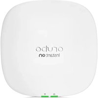

- HP MSM7XX CONTROLLERS CONFIGURATION GUIDE
- ABSTRACT
- ACKNOWLEDGMENTS
- WARRANTY
- CONTENTS
- WIRELESS CONFIGURATION
- WORKING WITH VSCS
- WORKING WITH CONTROLLED APS
- WORKING WITH VLANS
- CONTROLLER TEAMING
- MOBILITY TRAFFIC MANAGER
- AUTHENTICATION SERVICES
- SECURITY
- LOCAL MESH
- PUBLIC/GUEST NETWORK ACCESS
- WORKING WITH VPNS
- LLDP
- SFLOW
- WORKING WITH AUTONOMOUS APS
- MAINTENANCE
- SUPPORT AND OTHER RESOURCES
- A CONSOLE PORTS
- B RESETTING TO FACTORY DEFAULTS
- C NOC AUTHENTICATION
- D DHCP SERVERS AND COLUBRIS VENDOR CLASSES
- INTRODUCTION
- NEW IN THIS RELEASE
- USING THE MANAGEMENT TOOL
- STARTING THE MANAGEMENT TOOL
- ABOUT PASSWORDS
- ABOUT THE SECURITY WARNING
- USING AUTOMATED WORKFLOWS
- SETTING UP MANAGER AND OPERATOR ACCOUNTS
- ADMINISTRATIVE USER AUTHENTICATION
- PASSWORDS
- MANAGER USERNAME/PASSWORD RESET
- IMPORTANT
- CONFIGURING MANAGEMENT TOOL SECURITY
- ON ALL OTHER CONTROLLERS
- ALLOWED ADDRESSES
- ACTIVE INTERFACES
- CONFIGURING THE LOGIN PAGE MESSAGE
- CONFIGURING AUTO-REFRESH
- SETTING THE SYSTEM TIME
- NETWORK CONFIGURATION
- WORKING WITH NETWORK PROFILES
- ABOUT THE DEFAULT NETWORK PROFILES
- ON THE E-MSM
- TO DEFINE A NEW NETWORK PROFILE
- CONFIGURING IP INTERFACES
- TO ASSIGN AN IP ADDRESS TO A NEW INTERFACE ON THE E-MSM
- SELECT CONTROLLER >> NETWORK > VLANS TO OPEN THE VLANS PAGE
- CONFIGURING THE ACCESS NETWORK/LAN PORT INTERFACE
- ADDRESSING
- MANAGEMENT ADDRESS
- CONFIGURING THE INTERNET NETWORK/INTERNET PORT INTERFACE
- NETWORK ADDRESS TRANSLATION
- LIMIT NAT PORT RANGE
- SIZE OF PORT RANGE
- CONFIGURING THE PPPOE CLIENT
- CONFIGURING THE DHCP CLIENT
- STATIC ADDRESSING
- ADDITIONAL IP ADDRESSES
- CONFIGURING PORT SETTINGS
- STATUS LIGHT
- JACK
- NAME
- DUPLEX
- SPEED
- TRUNK TYPE
- TRUNK GROUP
- MAC ADDRESS
- CONFIGURING E-MSM720 PORTS
- TRUNK SETTINGS
- LINK SETTINGS
- CONFIGURING THE LAN/INTERNET PORT (MSM710, MSM760, MSM765ZL)
- CONFIGURING DHCP SERVICES
- CONFIGURING THE GLOBAL DHCP SERVER
- NOTE
- TO CONFIGURE THE GLOBAL DHCP SERVER
- ASSIGNING FIXED DHCP LEASES
- ASSIGNING PUBLIC IP ADDRESSES
- ASSIGNING PUBLIC IP ADDRESSES TO USERS
- DHCP SERVER LEASE TIME
- ADDRESS POOL
- CONFIGURING THE DHCP RELAY AGENT
- TO CONFIGURE THE GLOBAL DHCP RELAY AGENT
- UNDER SERVER, DEFINE THE FOLLOWING
- SELECT SAVE
- CONFIGURING GRE TUNNELS
- LOCAL TUNNEL IP ADDRESS
- REMOTE TUNNEL IP ADDRESS
- TUNNEL IP MASK
- GRE PEER IP ADDRESS
- BANDWIDTH CONTROL
- DATA RATE LIMITS
- BANDWIDTH LEVELS
- ASSIGNING TRAFFIC TO A BANDWIDTH LEVEL
- CUSTOMIZING BANDWIDTH LEVELS
- EXAMPLE
- DISCOVERY PROTOCOLS
- CDP CONFIGURATION
- LLDP CONFIGURATION
- LLDP AGENTS
- TRANSMIT
- RECEIVE
- LLDP SETTINGS
- TRANSMIT INTERVAL
- MULTIPLIER
- TIME TO LIVE
- GENERATE DYNAMIC SYSTEM NAMES
- PLACEHOLDERS
- TLV SETTINGS
- BASIC TLVS
- MANDATORY TLVS
- CHASSIS ID
- PORT ID
- OPTIONAL TLVS
- PORT DESCRIPTION
- SYSTEM NAME
- SYSTEM DESCRIPTION
- SYSTEM CAPABILITIES
- WLAN ACCESS POINT
- ROUTER
- MANAGEMENT IP ADDRESS
- TLVS
- MAC/PHY CONFIGURATION/STATUS
- DNS CONFIGURATION
- DNS SERVERS
- DYNAMICALLY ASSIGNED SERVERS
- OVERRIDE DYNAMICALLY ASSIGNED DNS SERVERS
- SERVER
- DNS ADVANCED SETTINGS
- DNS CACHE
- DNS SWITCH ON SERVER FAILURE
- DNS SWITCH OVER
- DNS INTERCEPTION
- DEFINING IP ROUTES
- CONFIGURING IP ROUTES
- ACTIVE ROUTES
- DEFAULT ROUTES
- PERSISTENT ROUTES
- PPTP CLIENT
- SETTINGS
- ABOUT PPTP CLIENT ROUTES (INTERNET PORT)
- ABOUT PPTP SERVER ROUTES (INTERNET PORT)
- NETWORK ADDRESS TRANSLATION (NAT)
- NAT SECURITY AND STATIC MAPPINGS
- NAT EXAMPLE
- VPN ONE-TO-ONE NAT
- IP QOS
- CONFIGURING IP QOS PROFILES
- CREATE THE PROFILES
- ASSIGN THE PROFILES TO A VSC
- CUSTOMIZING DIFFSERV DSCP MAPPINGS
- IGMP PROXY
- PORT TRUNKING
- DEPLOYMENT CONSIDERATIONS
- STATIC TRUNKS
- DYNAMIC TRUNKS
- CREATING A STATIC TRUNK
- CREATING A DYNAMIC TRUNK
- SELECT LACP TRUNK
- WIRELESS COVERAGE
- FACTORS LIMITING WIRELESS COVERAGE
- RADIO POWER
- ANTENNA CONFIGURATION
- INTERFERENCE
- PHYSICAL CHARACTERISTICS OF THE LOCATION
- CONFIGURING OVERLAPPING WIRELESS CELLS
- PERFORMANCE DEGRADATION AND CHANNEL SEPARATION
- SELECTING CHANNELS IN THE 2.4 GHZ BAND
- DISTANCE BETWEEN APS
- AUTOMATIC TRANSMIT POWER CONTROL
- SUPPORTING 802.11A AND LEGACY WIRELESS CLIENTS
- RADIO CONFIGURATION
- RADIO CONFIGURATION PARAMETERS
- REGULATORY DOMAIN
- OPERATING MODE
- WIRELESS MODE
- WHEN TO USE THIS MODE
- G
- A
- A TURBO
- CHANNEL WIDTH
- CHANNEL EXTENSION
- CHANNEL
- AUTOMATIC CHANNEL SELECTION
- MANUAL CHANNEL SELECTION
- INTERVAL
- TIME OF DAY
- AUTOMATIC CHANNEL EXCLUSION LIST
- ANTENNA SELECTION
- MSM320-R
- MSM
- ANTENNA GAIN
- MAX CLIENTS
- ADVANCED WIRELESS SETTINGS
- COLLECT STATISTICS FOR WIRELESS CLIENTS
- TX BEAMFORMING
- RTS THRESHOLD
- SPECTRALINK VIEW
- TX PROTECTION
- GUARD INTERVAL
- MAXIMUM RANGE (ACK TIMEOUT)
- AVAILABLE SETTINGS
- BEACON INTERVAL
- MULTICAST TX RATE
- TRANSMIT POWER CONTROL
- MAXIMUM OUTPUT POWER
- USE MAXIMUM POWER
- SET POWER TO
- AUTOMATIC POWER CONTROL
- WIRELESS NEIGHBORHOOD
- SCANNING MODES
- MONITOR MODE
- IDENTIFYING UNAUTHORIZED APS
- CREATING THE LIST OF AUTHORIZED APS
- VIEWING WIRELESS INFORMATION
- VIEWING ALL WIRELESS CLIENTS
- AP NAME
- RADIO
- IP ADDRESS
- USERNAME
- SSID
- DURATION
- SIGNAL
- NOISE
- SNR
- ACTION
- VIEWING INFO FOR A SPECIFIC WIRELESS CLIENT
- VIEWING WIRELESS CLIENT DATA RATES
- HIGH THROUGHPUT (HT) RATE TRAFFIC
- LEGACY RATE TRAFFIC
- WIRELESS ACCESS POINTS
- ACCESS POINT STATUS
- WIRELESS PORT
- FREQUENCY
- PROTOCOL
- MODE
- TX POWER
- TRANSMIT PROTECTION STATUS
- TX MULTICAST OCTETS
- TX UNICAST OCTETS
- TX FRAGMENTS
- TX MULTICAST FRAMES
- TX UNICAST FRAMES
- TX DISCARDS WRONG SA
- TX DISCARDS
- TX RETRY LIMIT EXCEEDED
- TX MULTIPLE RETRY FRAMES
- TX SINGLE RETRY FRAMES
- TX DEFERRED TRANSMISSIONS
- QOS LOW PRIORITY TX
- QOS MEDIUM PRIORITY TX
- QOS HIGH PRIORITY TX
- QOS VERY HIGH PRIORITY TX
- TX PACKETS
- TX DROPPED
- TX ERRORS
- RX PACKETS
- RX DROPPED
- RX MULTICAST OCTETS
- RX UNICAST OCTETS
- RX FRAGMENTS
- RX MULTICAST FRAMES
- RX UNICAST FRAMES
- RX DISCARDS NO BUFFER
- RX DISCARDS WEP EXCLUDED
- RX DISCARDS WEP ICV ERROR
- RX MSG IN BAD MSG FRAGMENTS
- RX MSG IN MSG FRAGMENTS
- RX WEP UNDECRYPTABLE
- RX FCS ERRORS
- CLEAR COUNTERS
- KEY CONCEPTS
- BINDING VSCS TO APS
- VIEWING AND EDITING VSC PROFILES
- THE DEFAULT VSC
- VSC CONFIGURATION OPTIONS
- ABOUT ACCESS CONTROL AND AUTHENTICATION
- USE CONTROLLER FOR: AUTHENTICATION
- USE CONTROLLER FOR: ACCESS CONTROL
- WHEN BOTH AUTHENTICATION AND ACCESS CONTROL ARE ENABLED
- WHEN ONLY AUTHENTICATION IS ENABLED
- WHEN NEITHER OPTION IS ENABLED
- SUMMARY OF VSC CONFIGURATION OPTIONS
- ACCESS CONTROL
- PRESENT SESSION AND WELCOME PAGE TO 802.1X USERS
- IDENTIFY STATIONS BASED ON IP ADDRESS ONLY
- LOCAL NAS ID
- VIRTUAL AP
- NAME (SSID)
- DTIM COUNT
- BROADCAST NAME (SSID)
- ADVERTISE TX POWER
- BROADCAST FILTERING
- BAND STEERING
- WIRELESS CLIENTS
- MAX CLIENTS PER RADIO
- ALLOW TRAFFIC BETWEEN NN WIRELESS CLIENTS
- CLIENT DATA TUNNEL
- QUALITY OF SERVICE
- ALLOWED WIRELESS RATES
- NOTES ON 802.11N
- VSC INGRESS MAPPING
- VSC EGRESS MAPPING
- DEFAULT USER DATA RATES
- MAX TRANSMIT
- MAX RECEIVE
- WIRELESS MOBILITY
- SUBNET-BASED MOBILITY
- FAST WIRELESS ROAMING
- WIRELESS SECURITY FILTERS
- RESTRICT WIRELESS TRAFFIC TO
- DEFAULT WIRELESS SECURITY FILTER DEFINITIONS
- INCOMING WIRELESS TRAFFIC FILTERS
- ACCEPTED
- BLOCKED
- OUTGOING WIRELESS TRAFFIC FILTERS
- CUSTOM WIRELESS SECURITY FILTER DEFINITIONS
- WIRELESS MOBILITY CONSIDERATIONS
- WIRELESS PROTECTION
- WPA
- KEY SOURCE
- ENABLED
- DISABLED
- WEP
- X AUTHENTICATION
- RADIUS AUTHENTICATION REALMS
- HTML-BASED USER LOGINS
- VPN-BASED AUTHENTICATION
- MAC-BASED AUTHENTICATION
- LOCATION-AWARE
- WIRELESS MAC FILTER
- WIRELESS IP FILTER
- EXAMPLES
- DHCP SERVER
- DHCP RELAY AGENT
- VSC DATA FLOW
- ACCESS CONTROL ENABLED
- VSC ON CONTROLLED AP
- INGRESS
- FEATURES
- EGRESS
- VSC ON CONTROLLER
- ACCESS CONTROL DISABLED
- USING MULTIPLE VSCS
- ABOUT THE DEFAULT VSC
- QUALITY OF SERVICE (QOS)
- PRIORITY MECHANISMS
- P
- VSC-BASED PRIORITY
- DIFFSERV (DIFFERENTIATED SERVICES)
- TOS
- IP QOS PROFILES
- UPSTREAM DIFFSERV TAGGING
- UPSTREAM/DOWNSTREAM TRAFFIC MARKING
- UPSTREAM TRAFFIC MARKING
- DOWNSTREAM TRAFFIC MARKING
- QOS EXAMPLE
- CREATING A NEW VSC
- ASSIGNING A VSC TO A GROUP
- PLUG AND PLAY INSTALLATION
- AUTOMATIC SOFTWARE UPDATES
- CENTRALIZED CONFIGURATION MANAGEMENT
- MANUAL PROVISIONING
- SECURE MANAGEMENT TUNNEL
- AP AUTHENTICATION
- AP LICENSING
- KEY CONTROLLED-MODE EVENTS
- DISCOVERY OF CONTROLLERS BY CONTROLLED APS
- DISCOVERY OVERVIEW
- DISCOVERY METHODS
- UDP BROADCAST DISCOVERY
- DHCP DISCOVERY
- DNS DISCOVERY
- DISCOVERY USING SPECIFIC IP ADDRESSES
- DISCOVERY ORDER
- UNPROVISIONED APS
- PROVISIONED APS
- DISCOVERY RECOMMENDATIONS
- DISCOVERY PRIORITY
- DISCOVERY CONSIDERATIONS
- FIREWALL
- NAT
- MONITORING THE DISCOVERY PROCESS
- VIEWING ALL DISCOVERED APS
- AUTHENTICATION OF CONTROLLED APS
- BUILDING THE AP AUTHENTICATION LIST
- GENERAL SETTINGS
- AUTHENTICATION INTERVAL
- AUTHENTICATE NOW
- USE FILE AUTHENTICATION LIST
- FILE LOCATION
- USE RADIUS AUTHENTICATION LIST
- RADIUS PROFILE
- RADIUS USERNAME
- USE THE LOCAL AUTHENTICATION LIST
- CONFIGURING APS
- OVERVIEW
- INHERITANCE
- BINDING VSCS TO GROUPS
- SYNCHRONIZING APS
- CONFIGURATION STRATEGY
- DISCOVER APS AND THEN CONFIGURE GROUPS
- CONFIGURE GROUPS AND THEN DISCOVER APS
- WORKING WITH GROUPS
- ADDING A NEW GROUP
- DELETING A GROUP
- BINDING A VSC TO A GROUP
- WORKING WITH APS
- MANUALLY ADDING A NEW AP
- DELETING AN AP
- MOVING AN AP TO A DIFFERENT GROUP
- USING DRAG-AND-DROP
- USING MENUS
- MOVING MULTIPLE APS BETWEEN GROUPS
- AP MODE #= LOCAL MESH MODE #= AP/LOCAL MESH MODE = MONITOR MODE = SENSOR MODE X= DISABLED
- ASSIGNING EGRESS VLANS TO A GROUP
- ASSIGNING COUNTRY SETTINGS TO A GROUP
- PROVISIONING APS
- PROVISIONING METHODS
- USING THE CONTROLLER TO PROVISION APS
- DIRECTLY PROVISIONING AN AP USING ITS MANAGEMENT TOOL
- DISPLAYING THE PROVISIONING PAGES
- ON A CONTROLLER
- ON AN AP IN ITS FACTORY-DEFAULT STATE
- PROVISIONING CONNECTIVITY
- INTERFACE
- ASSIGN IP ADDRESS VIA
- STATIC IP SETTINGS
- LOCAL MESH SETTINGS
- COUNTRY
- CAUTION
- X
- EAP METHOD
- PASSWORD / CONFIRM PASSWORD
- ANONYMOUS
- PROVISIONING DISCOVERY
- DISCOVER USING DNS
- DISCOVER USING IP ADDRESS
- PROVISIONING SUMMARY
- PROVISIONING EXAMPLE
- AEROSCOUT RTLS
- TO ENABLE AEROSCOUT SUPPORT
- VIEWING STATUS INFORMATION
- VALUES
- AP MAC ADDRESS
- ENGINE
- TAG STATES
- MU STATES
- TAG REPORT
- TAG ADJ MSG
- MU REPORT
- SOFTWARE RETRIEVAL/UPDATE
- MONITORING
- VLAN USAGE
- DEFINING A VLAN
- DEFINING A VLAN ON A CONTROLLER PORT
- ASSIGNING VLANS TO CONTROLLED APS
- USER-ASSIGNED VLANS
- VLAN ASSIGNMENT VIA RADIUS
- VLAN ASSIGNMENT VIA THE LOCAL USER ACCOUNTS
- TRAFFIC FLOW FOR WIRELESS USERS
- BINDING TO A VSC THAT HAS WIRELESS MOBILITY AND MOBILITY TRAFFIC MANAGER ENABLED
- BINDING TO A VSC THAT HAS WIRELESS MOBILITY AND SUBNET-BASED MOBILITY ENABLED
- TERMS USED IN THE TABLES
- TRAFFIC FLOW EXAMPLES
- EXAMPLE 1 OVERRIDING THE VSC EGRESS ON A CONTROLLER WITH A USER-ASSIGNED VLAN
- CONFIGURATION SUMMARY
- EXAMPLE 2 OVERRIDING THE EGRESS NETWORK IN A VSC BINDING WITH A USER-ASSIGNED VLAN
- RESULT
- TEAMING OVERVIEW
- TEAMING ON THE MSM760 AND MSM765ZL
- TEAMING ON THE E-MSM
- TEAM IP ADDRESS
- FIRMWARE UPDATES
- CENTRALIZED MONITORING AND OPERATION
- REDUNDANCY AND FAILOVER SUPPORT
- SCALABILITY
- CONTROLLERS/APS
- LICENSING
- NETWORKING
- PUBLIC ACCESS
- USERS
- FIRMWARE
- LIMITATIONS
- CREATING A TEAM
- ABOUT THE TEAM IP ADDRESS
- CONFIGURATION EXAMPLES
- TEAMING THREE MSM760S
- CONFIGURE CONNECTIVITY AND LICENSES ON EACH CONTROLLER
- CONFIGURE THE TEAM
- UNDER CONNECTIVITY
- TEAMING TWO E-MSM720S USING A DIRECT LINK
- CONTROLLER DISCOVERY
- SUMMARY BOX
- TEAMING LIGHT
- CONTROLLERS
- CONTROLLED APS
- NETWORK TREE
- TEAM: TEAM NAME
- VSC
- STATUS LIGHTS
- VIEWING DISCOVERED CONTROLLERS
- VIEWING TEAM MEMBERS
- TEAM CONFIGURATION
- ACCESSING THE TEAM MANAGER
- TEAM CONFIGURATION OPTIONS
- REMOVING A CONTROLLER FROM A TEAM
- REMOVE THE CONTROLLER FROM THE TEAM
- SELECT DELETE
- DISABLE TEAMING ON THE CONTROLLER
- EDITING TEAM MEMBER SETTINGS
- MANUALLY ADDING A CONTROLLER TO A TEAM
- DEFINE SETTINGS AS FOLLOWS
- DISCOVERY OF A CONTROLLER TEAM BY CONTROLLED APS
- FAILOVER
- SUPPORTING N + N REDUNDANCY
- PRIMARY TEAM MANAGER FAILURE
- REPLACING THE TEAM MANAGER
- MOBILITY SUPPORT
- SINGLE CONTROLLER TEAM OPERATING ALONE
- SINGLE CONTROLLER TEAM OPERATING WITH NON-TEAMED CONTROLLERS
- CONFIGURE CONTROLLER #3 AND
- MULTIPLE TEAMED AND NON-TEAMED CONTROLLERS
- THE MOBILITY DOMAIN
- NETWORK REQUIREMENTS
- HOME NETWORKS
- LOCAL NETWORKS
- MOBILITY CONTROLLER DISCOVERY
- CONTROLLER DISCOVERY AND TEAMING
- THIS IS THE PRIMARY MOBILITY CONTROLLER
- IP ADDRESS OF PRIMARY MOBILITY CONTROLLER
- CONFIGURING MOBILITY TRAFFIC MANAGER
- DEFINING THE MOBILITY DOMAIN
- DEFINING NETWORK PROFILES
- ASSIGNING A HOME NETWORK TO A USER
- DEFINING LOCAL NETWORKS ON A CONTROLLER
- ASSIGNING LOCAL NETWORKS TO AN AP
- CONFIGURING THE MOBILITY SETTINGS FOR A VSC
- IF NO MATCHING NETWORK IS ASSIGNED
- BINDING A VSC TO AN AP
- MONITORING THE MOBILITY DOMAIN
- NETWORKS IN THE MOBILITY DOMAIN
- IP SUBNET
- MASK
- VLAN ID
- HANDLER
- NETWORK
- MOBILITY CLIENTS
- DATA PATH
- STATUS
- FORWARDING TABLE
- PORT
- VSC ID
- VLAN
- AUTHORIZED
- LOCAL
- AGING
- MOBILITY CLIENT EVENT LOG
- DATE AND TIME
- CATEGORY
- OPERATION
- SCENARIO 1: CENTRALIZING TRAFFIC ON A CONTROLLER
- HOW IT WORKS
- CONFIGURATION OVERVIEW
- VSC CONFIGURATION
- NETWORK PROFILES
- VSC BINDING
- SCENARIO 2: CENTRALIZED TRAFFIC ON A CONTROLLER WITH VLAN EGRESS
- SCENARIO 3: CENTRALIZED TRAFFIC ON A CONTROLLER WITH PER-USER TRAFFIC ROUTIN
- USER ACCOUNTS
- SELECT ADD NEW ACCOUNT
- UNDER GENERAL
- SCENARIO 4: ASSIGNING HOME NETWORKS ON A PER-USER BASIS
- CONTROLLER 1 CONFIGURATION
- MOBILITY DOMAIN
- CONTROLLER 2 CONFIGURATION
- AP CONFIGURATION
- LOCAL NETWORK ASSIGNMENT
- SCENARIO 5: TRAFFIC ROUTING USING VLANS
- SELECT CONTROLLER >> VSCS > HP
- VLANS
- SCENARIO 6: DISTRIBUTING TRAFFIC USING VLAN RANGES
- SELECT CONTROLLER >> NETWORK > VLANS
- SELECT NET1. THE ADD/EDIT VLAN MAPPING PAGE OPENS
- SELECT CONTROLLER >> MANAGEMENT > DEVICE DISCOVERY
- VSC BINDING FOR GROUP
- USER AUTHENTICATION, ACCOUNTS, AND ADDRESSING
- AUTHENTICATION SUPPORT
- OTHER ACCESS CONTROL METHODS
- USER AUTHENTICATION LIMITS
- SUPPORTED 802.1X PROTOCOLS
- PROTOCOL DEFINITIONS
- CONFIGURING 802.1X SUPPORT ON A VSC
- AUTHENTICATION
- REMOTE
- GENERAL
- RADIUS ACCOUNTING
- CALLED-STATION-ID CONTENT
- CONFIGURING GLOBAL 802.1X SETTINGS FOR WIRED USERS
- SUPPLICANT TIMEOUT
- REAUTHENTICATION
- TERMINATE
- CONFIGURING GLOBAL 802.1X SETTINGS FOR WIRELESS USERS
- GROUP KEY UPDATE
- PERIOD
- CONFIGURING 802.1X SUPPORT ON AN MSM317 SWITCH PORT
- MAC-BASED FILTERING
- CONFIGURING GLOBAL MAC-BASED AUTHENTICATION
- CONFIGURING MAC-BASED AUTHENTICATION ON A VSC
- CONFIGURING MAC-BASED AUTHENTICATION ON AN MSM317 SWITCH PORT
- CONFIGURING MAC-BASED FILTERS ON A VSC
- ADDRESS LIST
- FILTER BEHAVIOR
- CONFIGURING MAC-BASED FILTERS ON AN MSM317 SWITCH PORT
- HTML-BASED AUTHENTICATION
- CONFIGURING HTML-BASED AUTHENTICATION ON A VSC
- CONFIGURING VPN-BASED AUTHENTICATION ON A VSC
- NO AUTHENTICATION
- LOCALLY-DEFINED USER ACCOUNTS
- VALIDITY AND SUBSCRIPTION PLANS
- VSC USAGE
- ACCOUNT PROFILES
- ABOUT THE DEFAULT AC PROFILE
- SUPPORTED ATTRIBUTES
- DEFINING A USER ACCOUNT
- DEFINING ACCOUNT PROFILES
- DEFINING SUBSCRIPTION PLANS
- PUBLIC IP ADDRESS
- ACCOUNTING PERSISTENCE
- USER ADDRESSING AND RELATED FEATURES
- USING THE INTEGRATED RADIUS SERVER
- PRIMARY FEATURES
- SERVER CONFIGURATION
- CONFIGURATION PARAMETERS
- RADIUS SERVER
- DETECT SSID FROM NAS-ID
- NUMBER OF ACCOUNTING SESSIONS
- MAXIMUM ACCOUNTING SESSIONS
- AUTHENTICATION UDP PORT
- ACCOUNTING UDP PORT
- SERVER AUTHENTICATION SUPPORT
- RADIUS AUTHORIZATION
- SHARED SECRET
- DEFAULT SHARED SECRET
- SHARED SECRET/CONFIRM SHARED SECRET
- USER ACCOUNT CONFIGURATION
- USING A THIRD-PARTY RADIUS SERVER
- CONFIGURING A RADIUS SERVER PROFILE
- CONFIGURATION PROCEDURE
- PROFILE NAME
- AUTHENTICATION PORT
- ACCOUNTING PORT
- RETRY INTERVAL
- AUTHENTICATION METHOD
- NAS ID
- ALWAYS TRY PRIMARY SERVER FIRST
- USE MESSAGE AUTHENTICATOR
- FORCE NAS-PORT TO INGRESS VLAN ID
- OVERRIDE NAS ID WHEN ACTING AS A RADIUS PROXY
- PRIMARY/SECONDARY RADIUS SERVER
- SERVER ADDRESS
- SECRET/CONFIRM SECRET
- AUTHENTICATION REALMS
- SUPPORT FOR REGULAR EXPRESSIONS IN REALM NAMES
- AUTHENTICATING MANAGER LOGINS USING A THIRD-PARTY RADIUS SERVER
- USING AN ACTIVE DIRECTORY SERVER
- SUPPORTED PROTOCOLS
- ACTIVE DIRECTORY CONFIGURATION
- ACTIVE DIRECTORY SETTINGS
- DEVICE NAME
- DOMAIN NETBIOS NAME
- WINDOWS DOMAIN
- CHECK ACTIVE DIRECTORY ACCESS WITH ATTRIBUTE
- JOIN
- PASSWORD
- JOIN REALM NOW
- ACTIVE DIRECTORY GROUPS ATTRIBUTES
- ADD NEW GROUP
- SAVE PRIORITY SETTINGS
- CONFIGURING AN ACTIVE DIRECTORY GROUP
- GROUP NAME
- ACTIVE
- ACCESS-CONTROLLED GROUP
- EFFECTIVE ATTRIBUTES
- CONFIGURING A VSC TO USE ACTIVE DIRECTORY
- FIREWALL PRESETS
- FIREWALL CONFIGURATION
- CUSTOMIZING THE FIREWALL
- MANAGING CERTIFICATES
- TRUSTED CA CERTIFICATE STORE
- INSTALLING A NEW CA CERTIFICATE
- CA CERTIFICATE IMPORT FORMATS
- DEFAULT CA CERTIFICATES
- CERTIFICATE AND PRIVATE KEY STORE
- STATUS INDICATOR
- ID
- ISSUED TO
- ISSUED BY
- CURRENT USAGE
- START/EXPIRATION DATE
- DELETE
- CERTIFICATE USAGE
- SERVICE
- AUTHENTICATE TO PEER USING
- NUMBER OF ASSOCIATED CAS
- CHANGING THE CERTIFICATE ASSIGNED TO A SERVICE
- ABOUT CERTIFICATE WARNINGS
- IPSEC CERTIFICATES
- IPSEC TRUSTED CA CERTIFICATES
- IPSEC MANAGE CA CERTIFICATES
- IPSEC LOCAL CERTIFICATE STORE
- IPSEC MANAGE LOCAL CERTIFICATE
- IPSEC X.509 CERTIFICATE REVOCATION LIST
- IPSEC MANAGE CERTIFICATE REVOCATION LIST
- CERTIFICATE EXPIRATION ALERTS
- MAC LOCKOUT
- ADDING A MAC LOCKOUT ADDRESS
- SIMULTANEOUS AP AND LOCAL MESH SUPPORT
- SINGLE RADIO APS
- MULTIPLE RADIO APS
- USING 802.11A/N FOR LOCAL MESH
- LOCAL MESH TERMINOLOGY
- LOCAL MESH OPERATIONAL MODES
- NODE DISCOVERY
- OPERATING CHANNEL
- LOCAL MESH PROFILES
- CONFIGURATION GUIDELINES
- CONFIGURING A LOCAL MESH PROFILE
- ENABLED/DISABLED
- TKIP
- AES/CCMP
- MESH ID
- MINIMUM SNR
- SNR COST PER HOP
- ALLOWED DOWNTIME
- MAXIMUM LINKS
- INITIAL DISCOVERY TIME
- PROVISIONING LOCAL MESH LINKS
- SAMPLE LOCAL MESH DEPLOYMENTS
- RF EXTENSION
- BUILDING-TO-BUILDING CONNECTION
- DYNAMIC NETWORK
- ACCESS LISTS
- THE PUBLIC ACCESS INTERFACE
- CONFIGURING GLOBAL ACCESS CONTROL OPTIONS
- USER AUTHENTICATION
- ALLOW ACCESS IF AUTHENTICATION TIMED OUT
- ADD IDLE-TIMEOUT TO RADIUS ACCOUNTING SESSION-TIME
- AUTOMATICALLY REAUTHENTICATE HTML-BASED USERS FOR NN MIN
- REAUTHENTICATE USERS ON LOCATION CHANGE
- MAXIMUM CONCURRENTLY AUTHENTICATED PUBLIC ACCESS USERS
- CLIENT POLLING
- POLLING INTERVAL
- CONSECUTIVE RETRIES
- USER AGENT FILTERING
- BLOCKED AGENTS
- ZERO CONFIGURATION
- SUPPORT APPLICATIONS THAT USE
- LOCATION CONFIGURATION
- LOCATION ID
- LOCATION NAME
- DISPLAY ADVERTISEMENTS
- PUBLIC ACCESS INTERFACE CONTROL FLOW
- CUSTOMIZING THE PUBLIC ACCESS INTERFACE
- SAMPLE PUBLIC ACCESS PAGES
- COMMON CONFIGURATION TASKS
- CUSTOMIZING THE LOGO
- DISPLAYING CUSTOM WELCOME AND GOODBYE PAGES
- DELIVERING DYNAMICALLY GENERATED CONTENT
- SUPPORTING SMARTPHONES
- CUSTOMIZING ERROR MESSAGES
- LOGOUT HOST NAME
- LOGOUT IP ADDRESS
- SETTING SITE CONFIGURATION OPTIONS
- ABOUT ASP VARIABLES
- ALLOW SUBSCRIPTION PLAN PURCHASES
- PRE-REQUISITES
- DISPLAY THE FREE ACCESS OPTION
- SUPPORT A LOCAL WELCOME PAGE
- USE FRAMES WHEN PRESENTING ADS
- ALLOW SSLV2 AUTHENTICATION
- REDIRECT USERS TO THE LOGIN PAGE VIA
- CUSTOMIZING THE PUBLIC ACCESS WEB PAGES
- SITE FILE ARCHIVE
- OVERWRITE CURRENT SITE FILES FROM ARCHIVE
- FTP SERVER
- USER
- CURRENT SITE FILES
- ADD NEW FILE
- RESET TO FACTORY DEFAULT CONTENT
- SITE FILE DESCRIPTIONS
- ADS.ASP
- ADS.JPG
- FAIL.ASP
- GOODBYE.ASP
- GRACEFUL_ENDING.JS
- INDEX.ASP
- LOGIN_ERROR_MESSAGE.ASP
- LOGO.GIF
- PAYMENT.ASP
- PAYPAL-CANCEL.ASP
- PAYPAL_ERROR.ASP
- PAYPAL-RETURN.ASP
- PROTOTYPE.JS
- PUBLIC-IP.ASP
- PURCHASE_APPROVED.ASP
- PURCHASE_FAILED.ASP
- REDIRECT.ASP
- REVIEW.ASP
- SESSION.ASP
- SESSION.JS
- SESSION_AJAX.ASP
- SESSIONWINDOW.JS
- SETFOCUS.JS
- STYLE.CSS
- SUBSCRIBE.ASP
- SUBSCRIPTION_DETAILS.ASP
- CONFIGURING THE PUBLIC ACCESS WEB SERVER
- OPTIONS
- PORTS
- MIME TYPES
- FILE EXTENSION
- MIME TYPE
- MIME TYPE IS TEXT-BASED
- MANAGING PAYMENT SERVICES
- PAYMENT SERVICES CONFIGURATION
- SERVICE SETTINGS
- PAYMENT METHOD: CREDIT CARD
- CURRENCY CODE
- TAX RATE
- AUTHORIZE.NET SERVICE
- PAYMENT URL
- LOGIN ID
- TRANSACTION KEY
- WORLDPAY SERVICE
- INSTALLATION ID
- RESPONSE PASSWORD
- OTHER CONFIGURATION ISSUES
- PAYPAL SERVICE
- USER ID
- USER PASSWORD
- SIGNATURE
- OVERRIDE DEFAULT PAYPAL URLS
- PAYPAL EXAMPLE
- GOGO INTERNET
- BILLING RECORD LOGGING
- SUSPEND PAYMENT SYSTEM WHEN LOG IS FULL OF QUEUED RECORDS
- CONFIGURE RECORD FORMATS
- PERSISTENCE
- SAVE QUEUED RECORDS EVERY NN MINUTES
- SAVE QUEUED RECORDS NOW
- EXTERNAL BILLING RECORDS SERVER PROFILES
- TYPE
- HOSTNAME/IP ADDRESS
- URL
- TRANSMISSION TIMEOUT
- USE THESE BACKUP SERVERS
- AVAILABLE BACKUP SERVERS
- RETRIES PER SERVER
- DELAY BETWEEN RETRIES
- SECRET KEY
- USE HTTPS
- VALIDATE SERVER CERTIFICATE
- USE HTTP AUTHENTICATION
- FAULT TOLERANCE
- RETRANSMIT UNTIL SUCCESSFUL
- STOP AFTER FAILED NNN RETRANSMISSIONS
- RECORD TRANSMISSION OVERVIEW
- BILLING RECORDS LOG
- NUMBER OF BILLING RECORDS
- SELECT THE ACTION TO APPLY TO ALL LOG RECORDS
- TABLE
- RECORD ID
- TRANSACTION ID
- TRANSACTION TIME
- CHARGE
- BILLING METHOD
- TRANSMISSION STATE
- LOCATION-AWARE AUTHENTICATION
- RETURNED INFORMATION
- CALLED-STATION-ID VALUE
- HP-SPECIFIC ATTRIBUTE: SSID
- HP-SPECIFIC ATTRIBUTE: GROUP
- WORKING WITH RADIUS ATTRIBUTES
- CONTROLLER ATTRIBUTES OVERVIEW
- CUSTOMIZING THE PUBLIC ACCESS INTERFACE USING THE SITE ATTRIBUTE
- DEFINING AND RETRIEVING SITE ATTRIBUTES
- RETRIEVING SITE ATTRIBUTES FROM A RADIUS SERVER
- DEFINING SITE ATTRIBUTES DIRECTLY ON THE CONTROLLER
- CONTROLLER ATTRIBUTE DEFINITIONS
- ACCESS REQUEST
- ACCT-SESSION-ID
- CALLED-STATION-ID
- CALLING-STATION-ID
- CHAP-CHALLENGE
- CHAP-PASSWORD
- CONNECT-INFO
- EAP-MESSAGE
- FRAMED-IP-ADDRESS
- FRAMED-MTU
- NAS-IDENTIFIER
- NAS-LP-ADDRESS
- NAS-PORT
- NAS-PORT-TYPE
- MESSAGE-AUTHENTICATOR
- SERVICE-TYPE
- STATE
- USER-NAME
- USER-PASSWORD
- VENDOR-SPECIFIC (MICROSOFT)
- MSCHAP-CHALLENGE
- MSCHAP-RESPONSE
- MSCHAPV2-RESPONSE
- VENDOR-SPECIFIC (WISPR)
- LOCATION-NAME
- LOCATION-ID
- LOGOFF-URL
- ACCESS ACCEPT
- CLASS
- SESSION-TIMEOUT
- VENDOR-SPECIFIC (COLUBRIS)
- COLUBRIS AV-PAIR
- ACCESS REJECT
- ACCESS CHALLENGE
- ACCOUNTING REQUEST
- ACCT-AUTHENTIC
- ACCT-DELAY-TIME
- ACCT-EVENT-TIMESTAMP
- ACCT-STATUS-TYPE
- ACCOUNTING RESPONSE
- USER ATTRIBUTES
- CUSTOMIZING USER ACCOUNTS WITH THE USER ATTRIBUTE
- DEFINING AND RETRIEVING USER ATTRIBUTES
- DEFINING ATTRIBUTES LOCALLY IN USER ACCOUNTS
- EMPLOYEE PROFILE
- GUEST PROFILE
- RETRIEVING ATTRIBUTES FROM A RADIUS SERVER
- PCM IDM SUPPORT
- USER ATTRIBUTE DEFINITIONS
- ACCOUNTING REQUESTACCESS ACCEPTACCESS REQUEST
- CHARGEABLE USER IDENTITY (CUI)
- NAS-IP-ADDRESS
- ACCT-INTERIM-INTERVAL
- IDLE-TIMEOUT
- REPLY-MESSAGE
- TERMINATION-ACTION
- TUNNEL-MEDIUM-TYPE
- TUNNEL-PRIVATE-GROUP-ID
- TUNNEL-TYPE
- MS-MPPE-RECV-KEY
- MS-MPPE-SEND-KEY
- COLUBRIS-INTERCEPT
- MSCHAP-ERROR
- ACCOUNTING STOP. AND INTERIM-UPDATE
- ACCT-SESSION-TIME
- ACCT-INPUT-GIGAWORDS
- ACCT-INPUT-OCTETS
- ACCT-INPUT-PACKETS
- ACCT-OUTPUT-GIGAWORDS
- ACCT-OUTPUT-OCTETS
- ACCT-OUTPUT-PACKETS
- ACCOUNTING STOP ONLY
- ACCT-TERMINATE-CAUSE
- ADMINISTRATOR ATTRIBUTES
- COLUBRIS AV-PAIR - SITE ATTRIBUTE VALUES
- ACCESS LIST
- DEFAULT SETTING
- HOW THE ACCESS LISTS WORK
- ACCOUNTING SUPPORT
- TIPS ON USING THE ACCESS LIST
- WITH CERTIFICATES
- REMOTE LOGIN PAGE
- SMTP REDIRECT
- DEFINING ACCESS LISTS
- ACTIVATING SITE ACCESS LISTS
- USER ACCESS LISTS
- SYNTAX
- ACCESS LIST EXAMPLE
- TOPOLOGY
- EVERYONE
- STUDENTS
- FACULTY
- CONFIGURATION FILE
- CUSTOM SSL CERTIFICATE
- CUSTOM PUBLIC ACCESS INTERFACE WEB PAGES
- LOADING CUSTOM PAGES FROM AN ARCHIVE
- LOADING INDIVIDUAL PAGES
- LOGIN PAGE
- TRANSPORT PAGE
- SESSION PAGE
- FAIL PAGE
- LOGO
- PLACEHOLDER
- HOSTING PAGES ON AN EXTERNAL WEB SERVER
- WELCOME PAGE
- LOGIN ERROR PAGE
- GOODBYE PAGE
- SECURITY ISSUES
- CUSTOM MESSAGE FILE
- DEFAULT USER INTERIM ACCOUNTING UPDATE INTERVAL
- DEFAULT USER BANDWIDTH LEVEL
- DEFAULT USER IDLE TIMEOUT
- DEFAULT USER QUOTAS
- DEFAULT USER ONE-TO-ONE NAT
- DEFAULT USER SESSION TIMEOUT
- DEFAULT USER PUBLIC IP ADDRESS
- DEFAULT USER SMTP SERVER
- DEFAULT USER URLS
- HTTP PROXY UPSTREAM
- IPASS LOGIN URL
- GLOBAL MAC-BASED AUTHENTICATION
- MULTIPLE LOGIN SERVERS
- POLLING
- SETTING THE URLS OF OTHER AV-PAIR VALUES
- REDIRECT URL
- NOC AUTHENTICATION
- HP WISPR SUPPORT
- WISPR LOGIN URL
- WISPR ABORT LOGIN URL
- WISPR REDIRECT PAGE
- WISPR ACCESS PROCEDURE
- TRAFFIC FORWARDING (DNAT-SERVER)
- MULTIPLE DNAT SERVERS
- COLUBRIS AV-PAIR - USER ATTRIBUTE VALUES
- ADVERTISING
- BANDWIDTH LEVEL
- DATA RATE
- ONE-TO-ONE NAT
- QUOTAS
- SMTP REDIRECTION
- EXAMPLE 3 PROXY SUPPORT ON
- EXAMPLE 4 PROXY SUPPORT OFF
- STATION POLLING
- COLUBRIS AV-PAIR - ADMINISTRATOR ATTRIBUTE VALUES
- ADMINISTRATIVE ROLE
- PUBLIC ACCESS INTERFACE ASP FUNCTIONS AND VARIABLES
- JAVASCRIPT SYNTAX
- FORMS
- HTMLSUBSCRIPTIONREQUEST
- FIELDS
- TO CREATE AN ACCOUNT
- TO EXECUTE A PAYMENT
- HTMLLOGINREQUEST
- HTMLLOGOUT
- FIELD
- FORM ERRORS
- ASP VARIABLES
- RADIUS
- SESSION STATUS AND PROPERTIES
- SESSION INPUT/OUTPUT/TOTALS
- SESSION QUOTAS
- IPASS SUPPORT
- WEB
- CLIENT INFORMATION
- SUBSCRIPTION PLAN INFORMATION
- OTHER
- PARAMETERS
- SESSION INFORMATION
- SESSION FUNCTIONS
- SESSION VARIABLES
- SECURING WIRELESS CLIENT SESSIONS WITH VPNS
- CONFIGURE AN IPSEC PROFILE FOR WIRELESS CLIENT VPN
- CONFIGURE L2TP SERVER FOR WIRELESS CLIENT VPN
- CONFIGURE PPTP SERVER FOR WIRELESS CLIENT VPN
- VPN ADDRESS POOL
- SECURING CONTROLLER COMMUNICATIONS TO REMOTE VPN SERVERS
- CONFIGURE AN IPSEC POLICY FOR A REMOTE VPN SERVER
- CONFIGURE PPTP CLIENT FOR A REMOTE VPN SERVER
- CONFIGURATION
- CONNECTION
- PPTP SERVER ADDRESS
- DOMAIN NAME(S)
- AUTO-ROUTE DISCOVERY
- LCP ECHO REQUESTS
- ACCOUNT
- KEEPING USER TRAFFIC OUT OF THE VPN TUNNEL
- ADDITIONAL IPSEC CONFIGURATION
- IPSEC VLAN MAPPING
- LOCAL GROUP LIST
- IPSEC SECURITY POLICY DATABASE
- ASSIGNING ADDRESSES TO USERS
- LLDP-MED
- SNMP SUPPORT
- CONFIGURING LLDP ON THE CONTROLLER
- CONTROLLER NAME
- EXPANDED CONTROLLER NAME
- UPDATE AP NAMES EVERY NN SECONDS
- CONFIGURING LLDP ON AN AP
- LLDP AGENT
- SUPPORTED TLVS
- MEDIA ENDPOINT DISCOVERY (MED) FEATURES
- ELIN LOCATION
- FAST START TIMER
- APPLICATION TYPE PROFILES
- APPLICATION TYPE
- VLAN TAGGING
- L2 PRIORITY
- DIFFSERV
- SFLOW PROXY
- MIB SUPPORT
- CONFIGURING AND ACTIVATING SFLOW
- GLOBAL SETTINGS
- ADVANCED CONFIGURATION
- MIB VERSION
- SFLOW ENABLED INTERFACES
- ADVANCED SFLOW CONFIGURATION
- COLLECTORS
- COLLECTOR CONFIGURATION SETTINGS
- TIMEOUT
- MAXIMUM DATAGRAM SIZE
- HP PMM COMPATIBILITY
- ACTIVE SFLOW AGENTS
- SFLOW AGENT SETTINGS
- DATA SOURCE
- GLOBAL IFINDEX
- INSTANCE
- PACKET FLOW SAMPLING
- COUNTER POLLING
- COLLECTOR
- SAMPLING RATE
- MAX HEADER SIZE
- COUNTER SAMPLING
- AUTONOMOUS AP DETECTION
- VIEWING AUTONOMOUS AP INFORMATION
- SWITCHING A CONTROLLED AP TO AUTONOMOUS MODE
- CONFIGURING AUTONOMOUS APS
- VSC DEFINITIONS
- MANAGEMENT WITH VLANS
- WORKING WITH THIRD-PARTY AUTONOMOUS APS
- VSC SELECTION
- CONFIG FILE MANAGEMENT
- MANUAL CONFIGURATION FILE MANAGEMENT
- BACKUP CONFIGURATION
- RESET CONFIGURATION
- RESTORE CONFIGURATION
- SCHEDULED OPERATIONS
- SOFTWARE UPDATES
- PERFORMING AN IMMEDIATE SOFTWARE UPDATE
- PERFORMING A SCHEDULED SOFTWARE UPDATE
- MANAGING LICENSES
- INSTALLED LICENSES
- EXPIRATION
- AMOUNT
- LICENSE MANAGEMENT
- LICENSE ORDERING INFORMATION
- RESET LICENSES
- INSTALL LICENSE FILE
- BACKUP LICENSE FILE
- GENERATING AND INSTALLING A FEATURE LICENSE
- GENERATING A LICENSE
- GENERATE LICENSE KEY FOR PROCURVE DEVICE
- ENTER HARDWARE ID AND CLICK ON NEXT BUTTON
- INSTALLING A LICENSE
- ONLINE DOCUMENTATION
- CONTACTING HP
- HP WEBSITES
- TYPOGRAPHIC CONVENTIONS
- MSM710 CONSOLE PORT
- USING THE CONSOLE PORT
- TO RESET MANAGER CREDENTIALS ON A CONTROLLER
- USING THE RESET BUTTON
- USING THE CONSOLE (SERIAL) PORT
- MAIN BENEFITS
- ACTIVATING A REMOTE LOGIN PAGE WITH NOC AUTHENTICATION
- ADDRESSING SECURITY CONCERNS
- SECURING THE REMOTE LOGIN PAGE
- AUTHENTICATING WITH THE LOGIN APPLICATION
- AUTHENTICATING THE CONTROLLER
- NOC AUTHENTICATION LIST
- SETTING UP THE CERTIFICATES
- INSTALL CERTIFICATES ON THE WEB SERVER
- DEFINE ATTRIBUTES
- INSTALL A CERTIFICATE ON CONTROLLER
- AUTHENTICATING USERS
- EXAMPLE 5 EXAMPLE
- EXAMPLE 6 EXAMPLE
- RETURNED VALUES
- EXAMPLES OF RETURNED HTML CODE
- SIMPLE NOC AUTHENTICATION EXAMPLE
- FORCING USER LOGOUTS
- WINDOWS SERVER 2003 CONFIGURATION
- CREATING THE VENDOR CLASS
- DEFINING VENDOR CLASS OPTIONS
- APPLYING THE VENDOR CLASS
- ISC DHCP SERVER CONFIGURATION
- TROUBLESHOOTING
Brand : HP
Model : ProCurve MSM317
Category : Access Point