
HER-252 - Cables for Computers and Peripherals Steren - Free user manual and instructions
Find the device manual for free HER-252 Steren in PDF.


| Product Type | Professional tone generator and UTP CAT 5/6 cable tester |
| Brand | Steren |
| Model | HER-252 |
| Power Supply | Two 9V square batteries (one for transmitter, one for receiver) |
| Tone Frequency | 130 kHz |
| Maximum Cable Mapping Distance | 300 m |
| Maximum Working Current (Transmitter) | < 70 mA |
| Maximum Working Current (Receiver) | < 150 mA |
| Maximum Signal Voltage | 8 Vp-p |
| Continuity Test Protection Voltage | 48 V |
| Low Battery Indicator Voltage | 6.5 V |
| Connectors Tested | RJ45 (8P/8C), RJ11 (6P/4C, 6P/2C), phone lines |
| PoE Compatibility | Yes (PoE SCAN mode) |
| Non-Contact Voltage Detection Range | 90 V - 1000 V AC |
| Functions | Cable tracking and identification, cable mapping and status, telecommunication device test, continuity detection, polarity and phone line validation, phone line test, NCV detection |
| Indicators | LED indicators for each pin (1-8 for RJ45, 2-7 for RJ11 6P/6C), SHORT, POL-/G, POL+/R, CONT, TEL, PoE SCAN, NCV |
| Receiver Features | 3.5 mm audio jack for earphones, lantern LED, volume control |
| Safety Cautions | Do not use on circuits >48 VDC, keep away from children, avoid water and dust, replace batteries regularly |
| Dimensions (approximate) | Transmitter: handheld design, receiver: similar size with tip (exact dimensions not provided) |
| Weight (approximate) | Lightweight, each unit approx. 200 g with battery (estimate) |
| Maintenance | Replace batteries when low, keep clean and dry, do not disassemble |
| Repairability | Refer to authorized Steren dealer for repair; no user-serviceable parts |
Frequently Asked Questions - HER-252 Steren
User questions about HER-252 Steren
0 question about this device. Answer the ones you know or ask your own.
Ask a new question about this device
Download the instructions for your Cables for Computers and Peripherals in PDF format for free! Find your manual HER-252 - Steren and take your electronic device back in hand. On this page are published all the documents necessary for the use of your device. HER-252 by Steren.
USER MANUAL HER-252 Steren
natural_image
Illustration of two handheld devices, one with a red tip and black handle, the other with a green control panel (no text or symbols visible)HER-252
natural_image
Solid dark blue rectangular shape with no visible text, symbols, or features.
natural_image
Simple icon of a person wearing glasses and holding a book, enclosed in a green circle (no text or symbols)PROBLEMAS Y SOLUCIONES....16
CONTENIDO


natural_image
Diagram of a remote control panel with a yellow pointer and mounting holes (no text or symbols)flowchart
graph TD
    subgraph Transmisor
        A1["0"] --> B1["0"]
        A2["0"] --> B2["0"]
        A3["0"] --> B3["0"]
        A4["0"] --> B4["0"]
        A5["0"] --> B5["0"]
        A6["0"] --> B6["0"]
        A7["0"] --> B7["0"]
        A8["0"] --> B8["0"]
        A9["0"] --> B9["0"]
        A10["0"] --> B10["0"]
        A11["0"] --> B11["0"]
    end
    subgraph Receptor
        B1["0"] --> C1["0"]
        B2["0"] --> C2["0"]
        B3["0"] --> C3["0"]
        B4["0"] --> C4["0"]
        B5["0"] --> C5["0"]
        B6["0"] --> C6["0"]
        B7["0"] --> C7["0"]
        B8["0"] --> C8["0"]
        B9["0"] --> C9["0"]
        B10["0"] --> C10["0"]
    end
    RJ-45["(8P/8C)"]
    RJ-11["(6P/4C)"]
natural_image
Illustration of a handheld device emitting sound waves with signal lines, no text or symbols presentPROBLEMAS Y SOLUCIONES
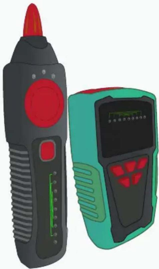
Professional tone generator and UTP CAT 5/6 cable tester, compatible with PoE
natural_image
Illustration of two handheld electronic devices, one with red tip and black handle, the other with green control panel (no text or symbols)HER-252
User Manual
V0.0/0917v

natural_image
Simple line drawing of a person wearing glasses and holding a book, enclosed in a green circle (no text or symbols)Before to use the product, please read carefully this manual to avoid any malfunction.
The info in this manual is shown as reference. Due to updates can exist differences. Consult our website www.steren.com to obtain the current version of this manual.
CAUTIONS
• This product is NOT a toy; keep it away from children.
- This device cannot be used by people with different abilities, unless they have preparation and supervision.
- Don't connect the test cables if they are damaged.
- Don't use or store the device in places where exist water or splashes.
- Do not to try disassemble or fix it.
- Do not exceed the maximum input limits that shown in the specifications.
• In case that you do not to use the device for long time, remove the batteries.
- Don't expose the device to dust, smoke or steam.
- Never use the the transmitter or the receiver in circuits with more than 48 VDC.
- Don't use the product if the cables are damaged, may cause damages to the equipment or cause injuries at yourself.
- Use only the indicated batteries (9V).
• To avoid wrong measurements, change the batteries regularly.
- Avoid to hit the receiver's tip, may cause damages.
INDEX
CONTENT......23
PARTS....24
TRANSMITTER....24
HOW TO USE....26
Tracking and identify the cables....26
Mapping and status of the cables....27
Test in telecommunication devices and routers....29
Continuity detection....30
Polarity and phone line validation....31
Phone line test....31
Non-Contact detection (NCV)....32
TROUBLESHOOTING....33
CONTENT



PARTS
TRANSMITTER
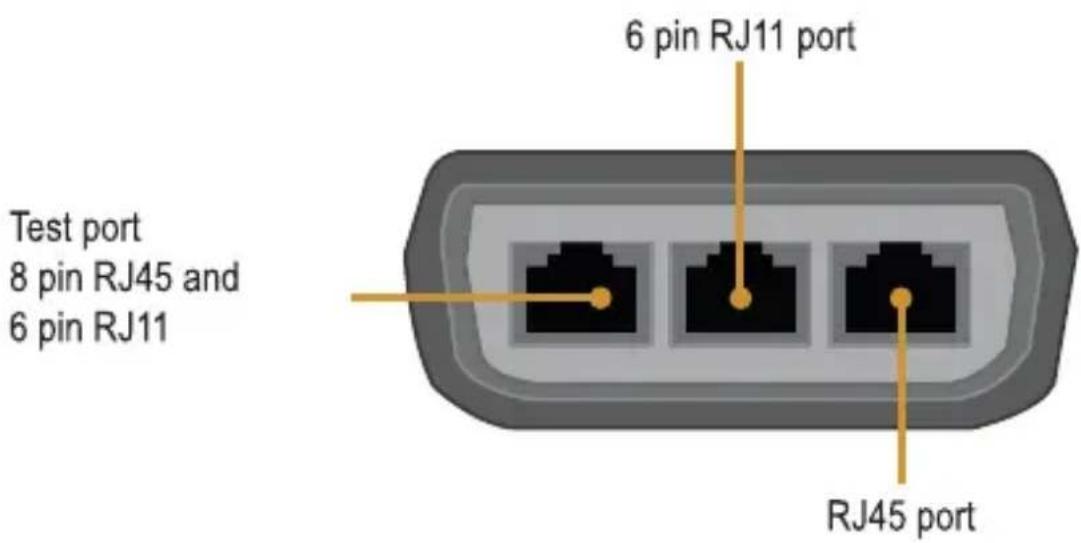
Ports
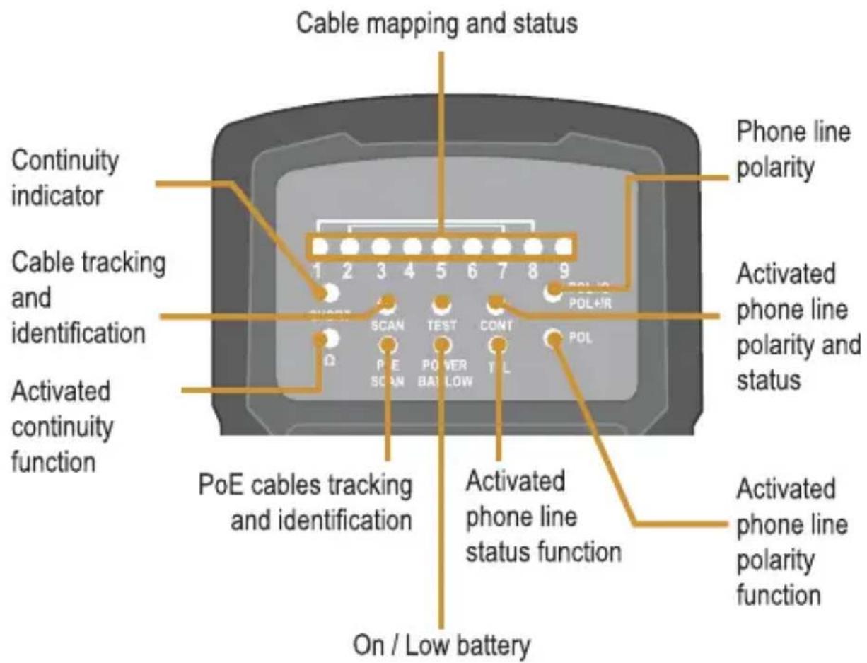
Buttons

LED indicators

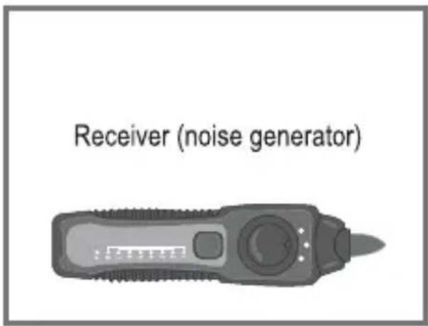
RECEIVER (tones generator)
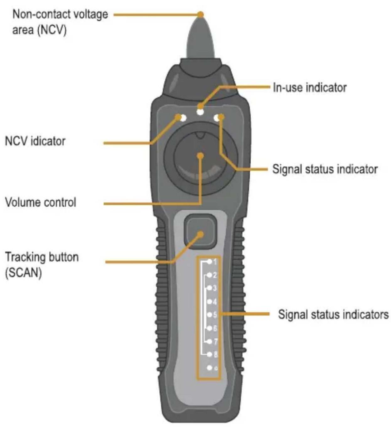
3.5 mm input*
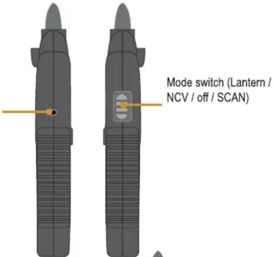
* You can use the earphones in places with many noise
Lantern
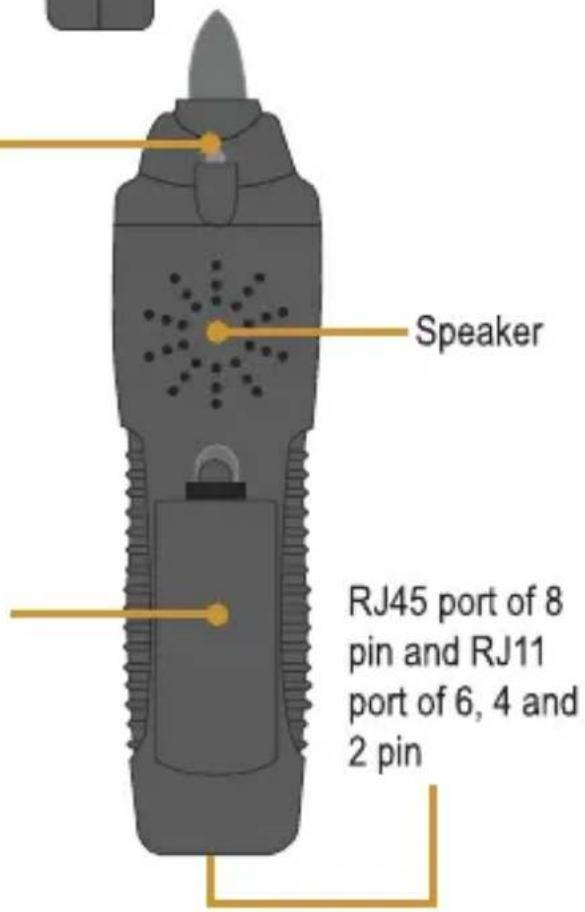
Battery compartment
Insert a 9 V battery. Ensure that place it with the correct polarity.
HOW TO USE
Cable tracking and identification
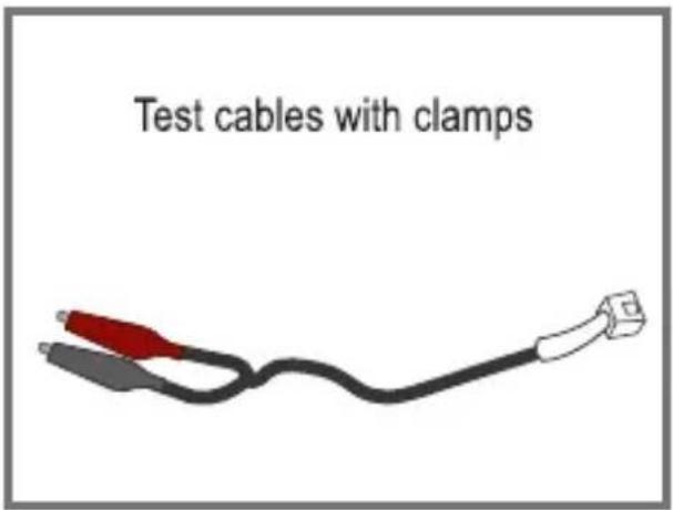
- Insert the testing cable into the transmitter. Connect the black clamp to ground and the red clamp to a jack or connector.
- In the transmitter press 🔍 to turn it on. Then, press the SCAN PoE button. If you want to track PoE networks press again the same button. The PoE SCAN indicator will remains on.
- In the receiver, slide the switch toward SCAN position.
- Close the receiver to the cable or wall and keep pressing the button to start tracking. The tone will be hiher as close as the cable is.
Note: The PoE SCAN function is used in switches and PoE networks. If the emitted tone is very weak, may be that the cable is not well connected into PoE switch or the jack is damaged, please change to SCAN tracking.
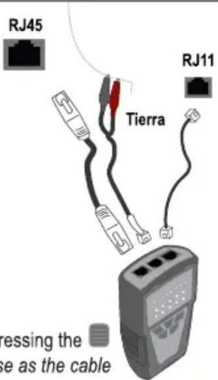

Cable mapping and status
- Connect the transmitter into a RJ45 or RJ11 port with the phone cable.
- In the transmitter press 🔒 to turn on it. Press the TEST button. The indicator TEST will flash slowly. Press the same button again if you want to increase the operating speed.
- Connect the receiver in the contrary side (until 300 m). Slide the switch to turn on.
The different connectors emmits their own tones and the LED indicators turn on by independent way.

RJ45 (8P/8C) LED indicators: The LED indicators of the transmitter and the receiver emits a 1-8s sequence in order.
RJ11 (6P/4C) LED indicators:
6P/6C turn on from 2 to 7 in sequence
6P/4C turn on from 3 to 6 in sequence
6P/2C turn on from 4 to 5 in sequence
If find a empty line, the indicators do not turn on

flowchart
graph TD
    subgraph RJ-45 (8P/8C)
        A["Transmitter"] --> B["Receiver"]
        C["Transmitter"] --> D["Receiver"]
        E["Transmitter"] --> F["Receiver"]
        G["Transmitter"] --> H["Receiver"]
        I["Transmitter"] --> J["Receiver"]
    end
    subgraph RJ-11 (6P/4C)
        K["Transmitter"] --> L["Receiver"]
        M["Transmitter"] --> N["Receiver"]
        O["Transmitter"] --> P["Receiver"]
        Q["Transmitter"] --> R["Receiver"]
        S["Transmitter"] --> T["Receiver"]
        U["Transmitter"] --> V["Receiver"]
        W["Transmitter"] --> X["Receiver"]
        Y["Transmitter"] --> Z["Receiver"]
    end
Each LED indicator both in transmitter as in receiver correspond to a pin. Watch as the indicators turn on, to check the status of the cable in RJ45 and RJ11 connectors.
Correct: If the indicators turn on one by one in stepped order that means that the pins are correctly connected.

flowchart
graph TD
    A["Input Block 1"] --> B["Process Step 1"]
    B --> C["Process Step 2"]
    C --> D["Process Step 3"]
    D --> E["Output Block 4"]
    E --> F["Output Block 5"]
    F --> G["Output Block 6"]
    G --> H["Output Block 7"]
    H --> I["Output Block 8"]
    I --> J["Output Block 9"]
    J --> K["Output Block 10"]
    K --> L["Output Block 11"]
    L --> M["Output Block 12"]
    M --> N["Output Block 13"]
    N --> O["Output Block 14"]
    O --> P["Output Block 15"]
    P --> Q["Output Block 16"]
    Q --> R["Output Block 17"]
    R --> S["Output Block 18"]
    S --> T["Output Block 19"]
    T --> U["Output Block 20"]
    U --> V["Output Block 21"]
    V --> W["Output Block 22"]
    W --> X["Output Block 23"]
    X --> Y["Output Block 24"]
    Y --> Z["Output Block 25"]
Short circuit: If two indicators turn on at the same time, that means this two pins have short circuit, (Example: pins 3 and 4 in short circuit).

flowchart
graph TD
    A["0"] --> B["AND"]
    B --> C["0"]
    C --> D["0"]
    D --> E["0"]
    E --> F["0"]
    F --> G["0"]
    G --> H["0"]
    H --> I["0"]
    I --> J["0"]
    J --> K["0"]
    K --> L["0"]
    L --> M["0"]
    M --> N["0"]
    N --> O["0"]
    O --> P["0"]
    P --> Q["0"]
    Q --> R["0"]
    R --> S["0"]
    S --> T["0"]
    T --> U["0"]
    U --> V["0"]
    V --> W["0"]
    W --> X["0"]
    X --> Y["0"]
    Y --> Z["0"]
    Z --> AA["0"]
    AA --> AB["0"]
    AB --> AC["0"]
    AC --> AD["0"]
    AD --> AE["0"]
    AE --> AF["0"]
    AF --> AG["0"]
    AG --> AH["0"]
    AH --> AI["0"]
    AI --> AJ["0"]
    AJ --> AK["0"]
    AK --> AL["0"]
    AL --> AM["0"]
    AM --> AN["0"]
    AN --> AO["0"]
    AO --> AP["0"]
    AP --> AQ["0"]
    AQ --> AR["0"]
    AR --> AS["0"]
Open: If an indicator turn on briefly and then is off, that means this pin is open. (Example: Pin 3 open).

flowchart
graph TD
    A["Input 1"] --> B["2-bit Lines"]
    B --> C["3-bit Lines"]
    C --> D["Output Lines"]
    style A fill:#f9f,stroke:#333
    style D fill:#bbf,stroke:#333
Crossed: If an indicator turn on briefly and other turn on by a second, that means the first pin is crossed with the second. (Example: Pins 3 and 4 are connected together).

flowchart
graph TD
    A["Node 1"] --> B["Node 2"]
    B --> C["Node 3"]
    C --> D["Node 4"]
    D --> E["Node 5"]
    E --> F["Node 6"]
    F --> G["Node 7"]
    G --> H["Node 8"]
    H --> I["Node 9"]
    I --> J["Node 10"]
    J --> K["Node 11"]
    K --> L["Node 12"]
    L --> M["Node 13"]
    M --> N["Node 14"]
    N --> O["Node 15"]
    O --> P["Node 16"]
    P --> Q["Node 17"]
    Q --> R["Node 18"]
    R --> S["Node 19"]
    S --> T["Node 20"]
    T --> U["Node 21"]
    U --> V["Node 22"]
    V --> W["Node 23"]
    W --> X["Node 24"]
    X --> Y["Node 25"]
    Y --> Z["Node 26"]
    Z --> AA["Node 27"]
    AA --> AB["Node 28"]
    AB --> AC["Node 29"]
    AC --> AD["Node 30"]
Test in telecommunication devices and routers
Important!
This function is used only to know if the cable is in good status, it can't be use to determine if the pins are crossed or if they are in short circuit.
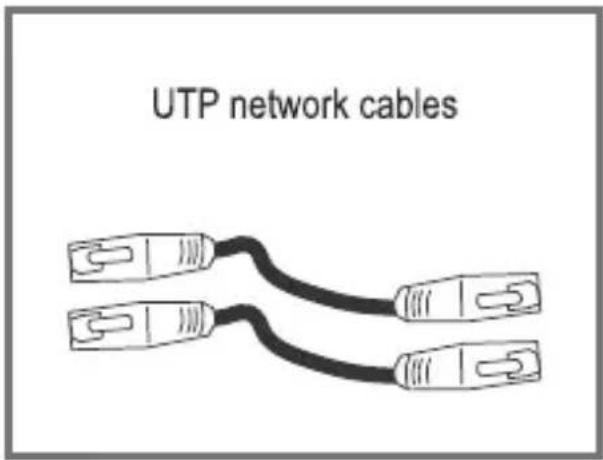
- Connect the network cable into RJ45 port of the transmitter, connect the other side into router port.
- In the transmitter press 🔒 to turn on it. Press the TEST INSERT button.
The TEST indicator will flash slowly. Press the same button again if you want to increase the operating speed.
If all indicators [1-8 G] turn on one by one, that means that the cable is right; if any of them turns on, the cable is damaged.

natural_image
Illustration of a RJ45 electrical connector with a cable and two red indicator lights (no text or symbols on the device itself)Continuity detection
ATTENTION!
Before to test ensure that the receiver is off.
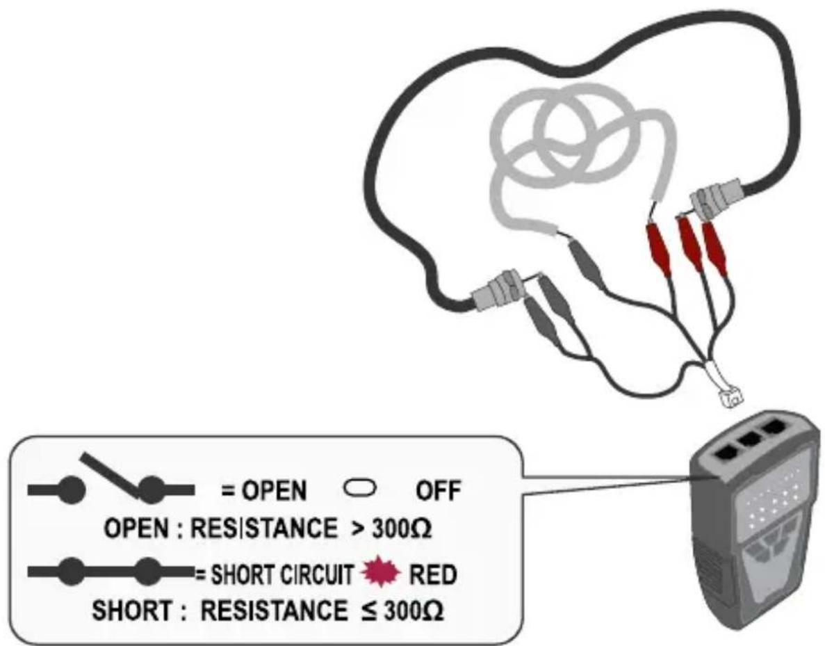
- Insert the testing cables into the transmitter. Connect the clamps as shown in the image.
- In the transmitter press 🔒 to turn on it. Then, press the 🔒 button.
If the SHORT indicator turn on, it means that the resistance is less than 300 Ω, if the indicator does not turn on the resistance is higher than 300 Ω.
Polarity and phone line validation
- Insert the cable with clamps into the transmitter. Connect the clamps into phone line connector directly.
- In the transmitter press ⏻ to turn it on. Then, press the 🔊 button.
The POL-/G, POL+/R indicator turn on in two colors (green and red) to indicate the polarity as shown below:
Red light: Red clamp with positive polarity (+); black clamp with negative polarity (-).
Green light: Red clamp with negative polarity (-); black clamp with positive polarity (+).
Without light: Line out of service.
Phone line test
- Insert the cable with clamps into the transmitter. Connect the clamps into phone line connector directly.
- In the transmitter press 🔒 to turn on it. Then, press the PCL TEL button twice. The TEL indicator will turn on.
During the proof, the CONT indicator turn on in two colors (green and red) to indicate the phone line status as shown below:
Red light: Red clamp with positive polarity (+); black clamp with negative polarity (-).
Green light: Red clamp with negative polarity (-); black clamp with positive polarity (+).
Without light: Line out of service.
The CONT indicator turn on in two colors (green and red) to shown the results of the test of the next way:
Red and green: Stand by mode
No brightness or dim light: Line out service.
Flash in red and green: Incoming call
Non-Contact voltage detection (NCV)
This function is used to find and identify cables with voltage, this ensure that not only the user's security if not also the equipment.
- In the receiver, slide the switch to NCV position.
- Press and hold the button, while bring near the receiver's tip toward the area where you want to search.
If the NVC indicator flashes quickly and the receiver emits a tone, that means that tested target have a current of 90 - 1000 V. If the receiver does not emit tones and the indicator does not light on, it means that the target have an alternating current less than 90 V or does not have current.

natural_image
Illustration of a handheld device emitting signal waves with a curved cable (no text or symbols)TROUBLESHOOTING
| Troublesolution | Solution |
| It cannot establish the connection with the receiver or the tones are weak | · Check that the volume control in the receiver is in right position.· Review the batteries status (im both devices) if is necessary change it.· Ensure that the switch in the receiver is in the “SCAN” or “LED”position. |
| The transmitter does not detectsthe signal in the telecommunication equipment | · Maybe there is conflict between the phone line signal and the transmitter signal. Restart your device. |
| Wrong results in the cable mapping | · Ensure that the connectors are RJ45/RJ11 and the cables are connected correctly.· If the LED indicators don’t works, probably are damaged, refers to an authorized dealer to make a revision of the equipment. |
| The NCV function does’not works | · Check that the switch is in the correct position.· Press and hold the SCAN button while you search.· Review the battery status. |
SPECIFICATIONS
Generator:
Input: 9 V --- (square battery) Tone frequency: 130 kHz Maximum distance of cable mapping: 300 m Maximum working current: < 70 mA Maximum signal voltage: 8 Vp-p
Continuity test
Tension protection: 48 V --- Low battery voltahe indicator: 6.5 V
Receiver:
Input: 9 V --- (square battery) Frequency: 130 kHz Maximu working current: < 150 mA
Specifications may change without notice

natural_image
Abstract blue circular logo with horizontal stripes (no text or symbols)STEREN
Customer Service Center
01 800 500 9000

- HER-252
- PROBLEMAS Y SOLUCIONES....16
- CONTENIDO
- CAUTIONS
- INDEX
- CONTENT
- PARTS
- TRANSMITTER
- LED indicators
- RECEIVER (tones generator)
- Battery compartment
- HOW TO USE
- Cable tracking and identification
- Cable mapping and status
- Test in telecommunication devices and routers
- Important!
- Continuity detection
- ATTENTION!
- Polarity and phone line validation
- Phone line test
- Non-Contact voltage detection (NCV)
- SPECIFICATIONS
- Generator:
- Continuity test
- Receiver:
- STEREN
Brand : Steren
Model : HER-252
Category : Cables for Computers and Peripherals