
TO-30 - Tractor Ferguson - Free user manual and instructions
Find the device manual for free TO-30 Ferguson in PDF.


| Product Type | Tractor |
| Brand | Ferguson |
| Model | TO-30 |
| Engine Type | 4-cylinder gasoline |
| Engine Displacement | 134 cu in (2.2 L) |
| Power Output | 30 hp (22.4 kW) |
| Fuel Type | Gasoline (unleaded) |
| Cooling System | Water-cooled |
| Transmission | 6-speed manual (4 forward + 2 reverse) |
| Drive | 2WD (rear) |
| PTO Type | Live PTO (540 rpm) |
| Hydraulic System | Ferguson hydraulic system |
| Steering | Manual (non-power) |
| Brakes | Mechanical drum brakes |
| Tire Size (Front) | 5.50-16 |
| Tire Size (Rear) | 11.2-24 |
| Overall Length | 120 inches (305 cm) |
| Overall Width | 64 inches (163 cm) |
| Overall Height (to steering wheel) | 66 inches (168 cm) |
| Weight (approximate) | 3,000 lbs (1,361 kg) |
| Fuel Tank Capacity | 12 gallons (45 L) |
| Maintenance Intervals | Oil change every 100 hours |
| Safety Features | Neutral safety switch, PTO shield |
Frequently Asked Questions - TO-30 Ferguson
User questions about TO-30 Ferguson
0 question about this device. Answer the ones you know or ask your own.
Ask a new question about this device
Download the instructions for your Tractor in PDF format for free! Find your manual TO-30 - Ferguson and take your electronic device back in hand. On this page are published all the documents necessary for the use of your device. TO-30 by Ferguson.
USER MANUAL TO-30 Ferguson
natural_image
Illustration of a street lamp against a blue background (no text or symbols)
natural_image
Illustration of a rural village with houses, trees, and a barn under a blue sky (no text or symbols)owner's manual
HARRY FERGUSON, INC., DETROIT, MICHIGAN

Ferguson park...
where your tractor was built.
In this modern plant, on Southfield Road in Detroit, your new Ferguson was built. This site occupies more than 72 acres. When the development of Ferguson Park is completed, the installation will be the most modern and complete of its kind . . . housing the manufacturing operations as well as the Engineering Laboratories, General Offices, Parts, Service and other departments of Harry Ferguson, Inc. Whenever you're in Detroit, you will be welcome at Ferguson Park.

HARRY FERGUSON, INC.
TRACTOR
WARRANTY
For a period of six (6) months from the date of delivery of a new Ferguson Tractor to the original purchaser thereof from a Ferguson dealer, Harry Ferguson, Inc., warrants all such parts thereof (except tires) which, under normal use and service, shall appear to Harry Ferguson, Inc., to have been defective in workmanship or material.
This warranty is limited to shipment to the purchaser, without charge except for transportation costs, of the part or parts intended to replace those acknowledged by Harry Ferguson, Inc., to be defective.
If the purchaser uses or allows to be used on the Ferguson Tractor, parts not made or supplied by Harry Ferguson, Inc., or if any Ferguson Tractor has been altered outside of its own factories or sources of supply, or if implements have been used which were unsuited and harmful to the Ferguson Tractor, then this warranty shall immediately become void. Harry Ferguson, Inc., does not undertake responsibility to any purchaser of a Ferguson Tractor for any undertaking, representation or warranty beyond those herein expressed.
Harry Ferguson, Inc., reserves the right to make changes in design or changes or improvements upon the Ferguson Tractor without any obligation upon it to install the same upon its tractors theretofore manufactured.

All genuine Ferguson Equipment is identified by a serial number on a Ferguson Name Plate. Refer to the serial number before ordering parts.

foreword
You have purchased the finest tractor of its kind in the world—the New Ferguson “30”. It has been built to exacting specifications with the utmost precision and balance of each moving part. New valve-in-head engine works in harmony with heavy rugged gearing. The Ferguson System combines the weight and power of tractor with forces of nature to give you unequaled performance with economy, ease of operation and usefulness on all your farm jobs.
This manual will help you maintain this high standard of performance with the New Ferguson "30" Tractor for years to come. You can make many minor adjustments yourself but some servicing will require the attention of your Ferguson Dealer. He knows the tractor inside and out ... has both experience and equipment to give you the most satisfactory service it is possible to obtain on this tractor.
May we wish you many years of economical and enjoyable farming with your New Ferguson "30" Tractor.
Ferguson
the Ferguson tractor...
with Ferguson hydraulic system
Your New Ferguson "30" Tractor is a precision-built unit designed for efficient performance, economy and ease of operation. It is extremely rugged . . . capable of giving outstanding service.
This tractor is especially designed to take full advantage of the Ferguson System. Whatever your requirements may be, your Ferguson Tractor and its hydraulically-controlled Ferguson System Implements will open up a new, more modern way of farming.

better farming for a better America!
periodic maintenance
- Proper maintenance, including periodic inspection and regular lubrication with the correct lubricant, is essential to long life and trouble free operation of your Ferguson Tractor. This section of your manual is devoted entirely to maintenance and should be referred to as a quick reference when minor servicing is performed.

PERIODIC MAINTENANCE
LUBRICATION
Care should be exercised when handling all lubricating oils. Open containers invite dirt which will greatly reduce filter element life and may cause serious damage to the engine.
The points listed below should be lubricated periodically. The numbers in the boxes beside each point indicate the hours of operation after which these points should be serviced. The parts and time intervals are marked in the illustrations for your convenience.

PRESSURE TYPE GREASE FITTINGS
NOTE: Clean fittings, pressure grease and wipe off excess lubricant.
Leveling Box
Lift Rod Leveling Fork
Front Axle Spindles
Steering Drag Links

CRANKCASE DIPSTICK
Check and maintain oil level at full mark.

TRANSMISSION DIPSTICK
Check and maintain oil level within arrow.

AIR CLEANER BOWL
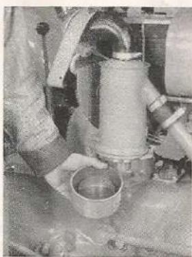
Clean and refill to level indicated in bowl with same weight oil as is used in the crankcase. Under very dusty conditions, service every five hours.

ENGINE CRANKCASE
Drain when warm and refill to full mark on dipstick. Crankcase capacity 5 U.S. quarts.
S.A.E. 30 above 50° Fahrenheit Temperature
S.A.E. 20 below 50° Fahrenheit Temperature
S.A.E. 10 below 10^ Fahrenheit Temperature


DISTRIBUTOR
Remove distributor cap, put one drop of light engine oil on breaker lever pivot and several drops on felt wick under rotor. Apply trace of cup grease on distributor cam.

GENERATOR
Put 10 drops of light oil in each oiler.

OIL FILTER ELEMENT
Replace element every other oil change. 6 U.S. quarts of crankcase oil required with the installation of new element.

TRANSMISSION, HYDRAULIC SYSTEM AND DIFFERENTIAL
√ Drain when oil is warm through three drain plugs and refill with straight mineral gear oil.
Finger-tip control lever must be in lower position to drain ram cylinder.
S.A.E. 90 above 50° Fahrenheit Temperature
S.A.E. 80 below 50° Fahrenheit Temperature

STEERING HOUSING OIL LEVEL
Maintain at 2 U.S. quarts or up to center of steering arms with transmission lubricant.

DISTRIBUTOR RESERVOIR
Fill with S.A.E. 20.

WHEEL BEARINGS
Remove, wash out and repack bearings with a good grade wheel bearing lubricant. Refer to page 40 for front wheel bearing adjustment and page 35 for rear wheel disassembling procedure.
MAINTENANCE
Your tractor is rugged and durable, however, just like any other complicated machine, it will give you much more satisfactory service if it is properly cared for. Experience has shown that periodic checks of certain parts are the best way to keep your tractor in top notch condition. It is highly advisable that at least once a year, preferably in the early spring before your tractor's busy season starts, you have your Ferguson Dealer give your tractor a complete check up. Having him make any repairs, that he suggests at that time, may save you costly breakdowns later in the season. In order to aid you in your periodic maintenance checks, the following table is provided. A more complete explanation of most items listed will be found elsewhere in this book.
Refer to lubrication details pages 2 and 3 for items which have an * (asterisk).
A. DAILY MAINTENANCE (10 hours)
- Crankcase Dipstick*
- Transmission Dipstick*
- Air Cleaner*
Inlet screen. Inspect for dirt and clean if necessary. This can be kept clean from the driver's seat.
- Pressure Fittings*
- Radiator
a. Coolant level should be approximately 1" above core.
b. Fins. Clean out foreign material.
- Fuel Tank
Fill with good clean regular grade gasoline through a screened funnel when the engine is stopped. Do not over fill. Be particularly careful not to spill fuel when engine is hot.
B. WEEKLY MAINTENANCE (50 hours)
- Battery Condition
a. Inspect cables and surface of battery. If wet, dirty or corroded, clean with a warm baking soda solution and apply grease to terminals to prevent further corrosion.
b. Keep water level 38 " above the plates. Add only distilled water. Fill to the top of the filler well. Care should be exercised not to disturb the washer.
- Tires
Inspect physical condition and check pressure. The tires should be inflated to the following pressure: 4.00 x 19—28 lbs., 6.00 x 16—28 lbs., 10.00 x 28—12 lbs. and 11.00 x 28—12 lbs.
- Nuts, Bolts and Screws
Check and tighten if necessary.
- Fuel Filter and Sediment Bowl
Shut off valve, empty bowl and wash filter in gasoline. If filter becomes coated with gum, or other deposits, from the gasoline, soak in solvent to remove.
C. SEMI-MONTHLY MAINTENANCE (100 hours)
-
Crankcase Oil*
-
Distributor*
-
Generator*
D. MONTHLY MAINTENANCE (200 hours)
- Spark Plugs Inspect condition. Clean spark plugs and set gap at 0.025.
- Oil Filter Cartridge*
- Bearing Retainer Nuts Tighten the six nuts on end of rear axle housings.
- Cylinder Head Cover Breather Pipe Remove and clean.
- Carburetor Shut off fuel valve, remove drain plug and drain carburetor. Remove inlet elbow and clean screen.
E. SPRING AND FALL MAINTENANCE (750 hours)
- Transmission Oil*
- Steering Housing Oil Level*
- Master Control Spring Grease threaded end of plunger and rod.
- Radiator Clean and flush radiator and refill with proper coolant.
- Gasoline Tank Clean and flush tank to remove rust, dirt and other foreign material.
- Air Cleaner a. Internal filter. Remove filter assembly and wash in gasoline. b. General. Check all connections for tightness.
- Distributor Reservoir*
F. YEARLY MAINTENANCE (1,000 hours)
- Front and Rear Wheel Bearings*
- Upkeep Wash tractor thoroughly. Remove all rust spots and touch up all areas with Ferguson Enamel.
operating instructions
The Ferguson Tractor is a precision built machine designed for efficient performance, economy and ease of operation. Although it is unusually rugged and capable of hard service, it should not be abused or neglected.
The Ferguson Tractor incorporates advanced principles, yet nothing difficult or mysterious is involved concerning its operation.
The suggestions outlined in this section will help you in obtaining long trouble-free service. By following them you will keep your tractor in good working order and avoid conditions likely to cause damage.

OPERATING INSTRUCTIONS

A. INSTRUMENTS AND CONTROLS
1. IGNITION SWITCH
Key operated ignition, ignition and light, and light switch on upper left side of instrument panel. "I" position closes ignition circuit. "IL" position closes both ignition and light circuit and "L" position closes light circuit only. When key is removed, switch is locked.
2. OIL PRESSURE GAUGE
Located on right side of instrument panel. Indicates the amount of pressure (not amount of oil) in the system.
3. AMMETER
Induction type located on left side of instrument panel. Indicates the rate of battery charge or discharge. Does not indicate generator output.
4. CHOKE
Button located at lower right hand side of instrument panel. Pulling the choke out provides a richer fuel mixture for faster and easier starting. Raising the choke knob will lock it in any position.
5. THROTTLE
Hand operated, located at the upper right of steering column below steering wheel. Pulling the throttle downward increases the engine speed.
6. GEAR SHIFT LEVER
Located in front of tractor seat on transmission housing. The four forward and one reverse speeds are indicated by the raised characters on the transmission housing cover. The individual gear shifts are performed by moving the shift lever toward the raised numerals on the transmission cover. Shift lever must be lifted to engage reverse.
7. STARTER SWITCH
A safety type switch operated by the gear shift lever. The starter switch is closed by lifting and moving the gear shift lever to the right and forward toward the raised "S" on the transmission cover. IT IS IMPOSSIBLE TO START YOUR FERGUSON TRACTOR WHILE IT IS IN GEAR.
8. HOOD LATCH
Toggle-type hood latch at lower left side of instrument panel. To open hood, pull up to release lever.
9. FINGER-TIP CONTROL LEVER
Located at the right of the tractor seat. The lever provides a manual control of the hydraulic system. To raise the linkage, the finger-tip control lever must be in top position. To lower the linkage, the finger-tip control lever is pushed to the lower position.
Located on the left side of the center housing. The lever in the rear position, as shown in the illustration engages the power take-off shaft and hydraulic pump. When the lever is in the forward position, both are disengaged.

natural_image
Close-up of a mechanical component with bolt holes and a curved handle (no visible text or symbols)The Lever in the forward position disengages the P.T.O. Shaft.
11. CLUTCH PEDAL
Foot operated at the left side of transmission housing. Depress pedal to disengage clutch.
12. LEFT WHEEL BRAKE PEDAL
Foot operated at the left side of transmission housing. Pressure on pedal, brakes left wheel for turning.
13. RIGHT WHEEL BRAKE PEDAL
Foot operated at the right side of transmission housing. Pressure on pedal, brakes right wheel for turning.
14. MASTER BRAKE PEDAL
Foot operated at the right side of transmission housing simultaneously engages both rear wheel brakes.
15. MASTER BRAKE PEDAL LOCK
Hand operated as master brake pedal is depressed. To lock brakes in engaged position, place pawl in ratchet.
16. FUEL SHUT-OFF VALVE
Located on the bottom left rear of the fuel tank. The valve is turned to the right to shut off the fuel flow. The valve opened two full turns to the left will allow gasoline to flow from the main supply. Opening the valve completely permits the use of a reserve gallon of fuel. Operate on reserve position one hour each day to keep reserve passage clean.
17. DOUBLE HINGE SEAT
The seat can be set back to enable the operator to stand and can be hinged upside down to keep it dry. The seat bracket can be adjusted forward or rearward.
Fuel Valve and Sediment Bowl.

natural_image
Close-up of mechanical components with no visible text or symbolsFuel Valve Knob.

natural_image
Vintage-style industrial lamp with a metallic body and label (no readable text or symbols)
natural_image
Black-and-white photo of a person operating a helicopter with a large satellite dish and mechanical equipment (no visible text or symbols)Ferguson Double Hinge Seal.
B. BREAKING-IN PERIOD
Your Ferguson Tractor has been carefully developed to furnish you many thousands of hours of working satisfaction. In order to maintain its efficiency and high standard of performance, it is essential that special care be given to your tractor during the first 50 hours of operation.
- Keep your tractor on light work for the first 50 hour period. However, after each 10 hour interval, operate tractor under full load for five or ten minutes.
- Use low transmission speeds when pulling heavy loads while engine is new.
- Change crankcase break-in oil after first 50 hours of operation.
- Change transmission break-in oil after first 50 hours of operation.
- Call your Ferguson Dealer for first 90-day check up.
- Tighten all nuts, bolts and screws frequently during break-in period.

Keep straw and other inflammable material away from exhaust pipe to prevent fire.
The skill of the operator in becoming familiar with the controls, in relation to the circumstances encountered, will determine the flexibility of the tractor and implement. For economical and successful operation of your Ferguson Tractor, the following operating principles should be followed:
natural_image
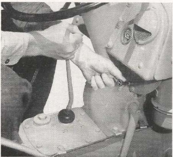
Close-up of hands operating a mechanical component with a valve and housing (no visible text or symbols)Starting the Ferguson Tractor with the Safety Starter.
STARTING THE ENGINE
-
Open Fuel shut-off valve by turning two full turns to the left from the closed position.
-
Turn ignition key to "I" position.
-
Move throttle lever 18 to 14 open position.
-
Pull out and hold choke in open position.
-
Disengage clutch by pushing clutch pedal down.
-
Engage Ferguson Safety Starter by lifting gear shift lever slightly and pushing to the right, then forward to the "S" position.
-
Release choke as soon as engine runs smoothly.
-
Do not "rev-up" or race the engine immediately after starting. Cold oil cannot circulate freely to all moving parts.
-
Allow the engine to reach its normal operating temperature before working the tractor. During cold weather, it will be noted that the oil pressure gauge will register a higher pressure. If this condition exists, the engine should be run at an idle speed until the pressure reaches its normal position.

natural_image
Cartoon illustration of a worker installing or adjusting a door panel, with no visible text or symbolsAlways open doors before starting tractor engine.
OBSERVING THE INSTRUMENTS
Form the habit of looking at the oil pressure gauge after starting the tractor. If it does not quickly register 15 to 30 pounds pressure, stop the engine immediately and determine the cause. Serious damage will result if the engine is operated without sufficient oil pressure even for a very short time. The ammeter readings should also be noted frequently while operating the tractor. Whenever any abnormal readings appear stop the tractor and determine the cause.
STARTING THE TRACTOR IN MOTION
- Make sure the brakes are released.
- Depress clutch fully and move gear shift lever to desired gear.
- Increase engine speed slightly and release clutch pedal slowly.
- Remove foot from clutch pedal and increase throttle setting until desired speed is obtained.
NOTE: The gear shift lever must not be lifted when selecting the forward gears.

DRIVING THE TRACTOR
Easy steering of the front wheels permits flexible maneuverability. The independent wheel brakes can
be used to assist front wheel turning when making short turns.
NOTE: Sharply braking one wheel causes wasteful wear of the tires and brakes and, therefore, only should be done when short turns are needed.

WARNING
The individual wheel brake should not be used to make sharp turns while traveling at high speeds.
CHOOSING THE CORRECT GEAR
The correct working gear can only be obtained by an intelligent selection by the operator. The basic factors involved in this selection are: (1) type of implement used, (2) field conditions encountered, (3) load subjected to the tractor and (4) the ground speed to effectively perform the operation.
Operating the tractor, in a low gear with a high engine speed, and relatively light engine load is a waste of fuel and time. Any gasoline engine operating at a high speed, with a light load, is running with a high manifold vacuum and low compression pressure which causes inefficient combustion. Noticeable racing of the engine is an indication of this condition.
Operating the tractor under load in a high gear, or when an excessive load is involved for the selected gear and throttle setting, overloads the engine and can cause serious damage and wear. When this condition exists, the engine is running with a low manifold vacuum, and relatively higher compression pressure, and is noticeable by a lugging sound of the

natural_image
Cartoon illustration of a person riding a large tractor, no text or symbols presentBring the tractor to a complete stop before shifting gears.
engine. Excessive wear and overheating will result from this overloading condition.
A TEST FOR OVERLOADING
With the tractor in motion, set the throttle half way open. Then quickly pull the throttle fully open. If the tractor speeds up rapidly, the engine is not overloaded. If the tractor picks up speed slowly, the engine is overloaded and should be shifted to the next lower gear. When operating on hills, the above test might indicate overloading, however, this is not harmful as it is compensated for when coming down hill. It is the continuous overloading which must be avoided.
STOPPING THE TRACTOR
Depress the clutch pedal while at the same time reducing the engine speed. Apply the brakes, as needed, using the master brake pedal. When tractor motion is stopped, move gear shift lever to neutral and set the brakes. Shut the tractor off by turning ignition switch to "off" position. At the end of the working day, turn the fuel shutoff valve to "off" position.

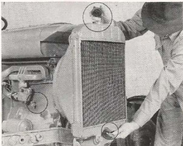
Whenever radiator is drained, be sure cap is removed, that both drain cocks are open, and that they positively drain.
D. USING THE FERGUSON SYSTEM
ATTACHING AN IMPLEMENT
- Back the tractor so it is centered with the implement, having the lower links above the cross-shaft.
- Lower the links by pushing the finger-tip control lever completely forward.
- Dismount tractor on left-hand side.
- Attach the lower left link by rocking tractor slightly backward or forward to align the pin with ball socket. Insert linchpin.

natural_image
Industrial machinery setup with a worker operating a large vehicle (no visible text or symbols)Attaching Left Lower Link.
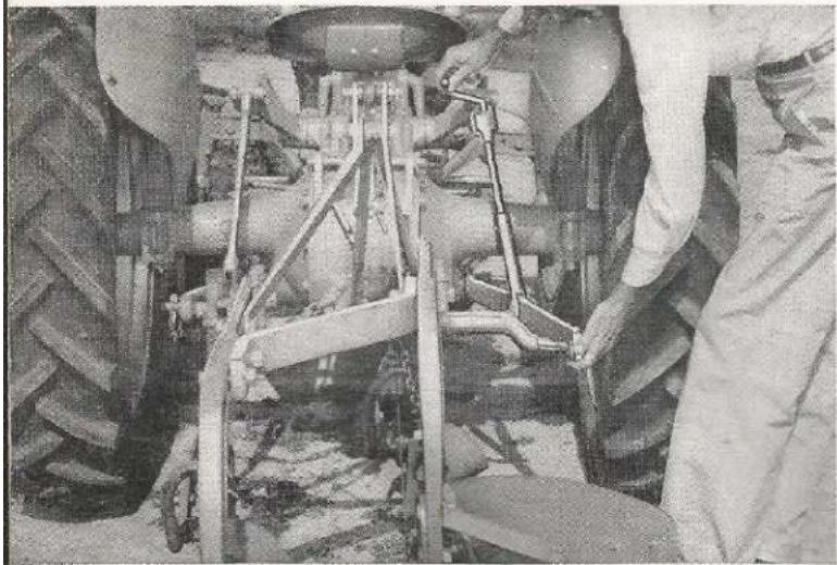
- Attach the lower right link using the leveling crank to bring the ball joint in line with the attaching pin. Insert linchpin.
- Attach the upper link to the implement. When seated on the tractor, attach the upper link to the
natural_image
Close-up of a person working on a vehicle chassis with visible structural components and no text or symbolsAttaching Right Lower Link.
tractor by moving the tractor slightly backward or forward to line up the connection so the pin can be inserted.
NOTE: To level the implement, level the lower links by turning the hand crank on the right lift rod, until the circular groove on the rod matches the top of the fork into which it threads.
IMPORTANT: Keep linkage ball-joint clean but never lubricate.

natural_image
Close-up of a tractor's lower body showing large tires and mechanical arms (no visible text or symbols)Attaching Upper Link to Tractor.
RAISING AND TRANSPORTING IMPLEMENTS
Engage the hydraulic pump by moving power take-off lever to the rear position. Any lift type implement can be easily raised simply by pulling the finger-tip control lever to the top position. When transporting implements in the raised position, turn the level-

natural_image
Close-up of a person using a handheld tool, no visible text or symbolsLeveling an implement.
ing crank counter-clockwise until check chains become tight to prevent side-sway of implement.
OPERATING WITH SOIL ENGAGING IMPLEMENTS
When a soil engaging implement is in transport position, it may be lowered to working position by moving the finger-tip control lever downward. This releases oil from the hydraulic system which permits the implement to lower by its own weight.
Just as soon as the implement reaches the desired depth (determined by the setting of the finger-tip control lever), the release of oil from the system is automatically stopped. As long as the soil texture remains the same, the implement will remain at that depth. However, if the soil texture changes it will be necessary to move the finger-tip control lever slightly lower in heavier soils or slightly higher in lighter soils to maintain uniform depth.
On uneven ground, the expansion and contraction of the automatic control spring regulates the flow of

natural_image
Illustration of a farmer operating a tractor with a large tire, set against a rural landscape background (no text or symbols)Drive carefully on the highway, observing all traffic rules.
oil into and out of the system, tending to keep the implement at uniform working depth.
To assist the operator in selecting the approximate same depth or draft each time the implement is lowered from the raised position, the wing nut stop assembly should be positioned on the quadrant so the control lever can be immediately placed. However, the finger-tip control lever can be varied from this position if necessary.
CAUTION: The operator of a tractor must realize that the implement attached to the tractor has been built to work best at a given ground travel speed. For instance, Ferguson Plows are built to operate in second gear. A slower or faster speed will not give the proper turning and pulverizing of the soil. Also,

natural_image
Close-up of hands operating a mechanical lever mechanism (no visible text or symbols)Set the Control Lever Stop Assembly for approximate depth settings.
faster speeds increase the chances of damaging the tractor or implement. While the Ferguson System provides adequate, automatic protection under normal operation, it should be kept in mind that the force at which an implement strikes an obstruction varies as the square of the speed. If a Ferguson Tractor is operating in third gear at 4.71 miles per hour (1,500 engine r.p.m.), it would have almost twice the striking force compared to operating in second gear at 3.42 miles per hour (1,500 engine r.p.m.).
It is much better to use the increased power of the new Ferguson Tractor by pulling larger implements rather than by traveling at higher speeds. For example, use a 3 bottom 12" plow in second gear instead of a 2 bottom 14" plow in third gear.
Third gear is meant to be used with implements which operate above the ground such as mowers, wagons, spike tooth harrow, etc. Fourth gear is used for road transport, raking and rotary hoeing.
DETACHING IMPLEMENTS
- Select level ground area, level the implement with leveling crank and lower to the ground.
- While seated on the tractor, detach upper link from tractor by moving tractor slightly backward or forward, if necessary, to remove upper link clevis pin.
- Detach right bottom link. Adjust the leveling crank to free strain on ball socket joint if necessary.
- Detach left bottom link.
NOTE: Always place linchpins in their proper clips on lower links.
USING EXTERNAL HYDRAULIC CYLINDER
Two external hydraulic outlets are incorporated at the front of the tractor center housing cover. These are for the purpose of utilizing the hydraulic system of the tractor with external cylinders as used on some Ferguson Implements. A control drop-valve assembly attached to right hand inspection plate is needed to control and release the oil in the external cylinder. Directions for using supplementary external cylinders on Ferguson Implements such as the Corn Picker and the Manure Loader will be found in the manuals which accompany the implements.
E. DRAWBAR INSTALLATION AND POWER TAKE-OFF OPERATION
STANDARD DRAWBAR
The drawbar for your Ferguson Tractor is easily attached for conventional pull-type hitching. The drawbar can be adjusted vertically, adapting it to the height of the implement.
CAUTION: The drawbar should be adjusted to provide sufficient weight on the front wheels for steering and safety.

natural_image
Front view of a tractor's front wheel and suspension system (no visible text or symbols)Drawbar with Stays in place.
To attach the drawbar:
- Lower the lower links and level them.
- Place the drawbar on the ground. Attach the correct stay links to the respective ends of the drawbar. (The stay with the chain attached, mounts to the right.) Lift and set the assembly on the tractor lower links.
- Pin top of stay links to tractor upper link connection and fasten with linehpin.
- Place one end of the drawbar then the other in the ball joints of the lower links and fasten linchpins.
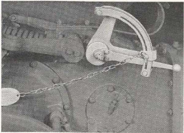
- Lock finger-tip control lever in down position with drawbar chain and wedge assembly. (Shift power take-off to disengaged position if power take-off operation is not desired.)
CAUTION: If a power take-off implement is used and the finger-tip control lever is raised, the stay links will be collapsed by the lift arms raising. Only when the corn picker drop valve assembly is mounted on the tractor, should the drawbar chain and wedge assembly be left off.
natural_image
Mechanical assembly with linkage and mounting flange components (no visible text or symbols)Finger-tip Control Lever locked down with Chain and Wedge Assembly.
- Adjust drawbar to desired height by loosening the bolts on the stay links and lengthening or shortening as required. The standard height is obtained when the notches on the stay links line up.

POWER TAKE-OFF
The power take-off on your Ferguson Tractor transfers engine power direct to mounted or drawn implements, or if equipped with a pulley assembly, to belt driven equipment.
To operate the power take-off shaft, the power take-off lever must first be engaged. This is accomplished by disengaging the clutch and moving the lever rearward. The power take-off shaft is controlled by the clutch pedal.

natural_image
Close-up of a mechanical component with a circular flange and bolted joints (no visible text or symbols)P.T.O. Lever in engaged position.
The 1 ^1/8 " power take-off shaft projects from the rear of the center housing. A removable cap encloses the splined end of the shaft. When the engine is run-

natural_image
Cartoon illustration of a person riding a tractor with a large tire, no text or symbols presentNever wear loose or sloppy clothing around tractor's moving parts.
ning at 1,500 r.p.m. (throttle about 23 open) the speed of the power take-off shaft is 545 r.p.m. This conforms with the American Society of Agricultural Engineers standard power take-off speed recommendation and most power take-off driven equipment is designed to operate at this speed.
POWER TAKE-OFF ADAPTERS (Accessories)
The power take-off adapters for the Ferguson Tractor have a 1 38'' spline and meet the A.S.A.E. requirements for a standard tractor hitch. Therefore, it is possible to attach any power take-off driven implement, which meets A.S.A.E. standards, to the Ferguson Tractor.

natural_image
Mechanical assembly with metal frame and hanging weights (no visible text or symbols)P.T.O. Adapter with V-extension Drawbar.

natural_image
Close-up of a mechanical device with no visible text or symbolsP.T.O. Adapter with Swinging Drawbar.
CAUTION: Keep power take-off shields in place at all times.
Two adapters are available for use with the Ferguson Tractor according to the type of hitch used.
The CLO-8920 Conversion Kit is used with the standard drawbar arrangement, however, a V-extension is needed to meet A.S.A.E. specifications.
The ATO-88 Conversion Kit includes the swinging drawbar with the adapter. The swinging drawbar (accessory) permits easier turning, as the angle of pull pivots closer to the tractor than when using a fixed drawbar.
NOTE: When replacing check chain brackets, it is essential that the chain be attached in the top hole of the bracket.
BELT PULLEY (Accessory)
The belt pulley attachment for the Ferguson Tractor is a self-contained unit with a 9" diameter and 6½" width pulley. The ratio of the speeds of the pulley to the power take-off shaft and engine is 1.87 to 1 and 1 to 1.473, respectively. The pulley speed is 1,359 r.p.m. at 2,000 engine r.p.m. giving a belt speed of 3,120 feet per minute.

natural_image
Mechanical assembly diagram showing a rotating component with directional arrows indicating motion (no text or symbols)The three mounting positions of the Belt Pulley.
To attach the belt pulley, remove the cover of the power take-off shaft and the check chain brackets. The pulley can be mounted in any of three positions, horizontally on either side of the shaft to give correct direction of rotation, or vertically with the pulley's edge toward the ground.
CAUTION: Never mount the pulley to the top position as the bearing will not receive proper lubrication. When installing the pulley, do not force in position with mounting bolts as breakage may result.
The pulley mechanism is lubricated by 34 pint of the same grade lubricant as is used in the transmission. Always keep oil level to filter plug.
IMPORTANT: To avoid static electricity when using belt and pulley, ground the tractor by wrapping a chain around front axle and dropping one end on the ground.
The table below is for the purpose of determining the size of the driven pulley necessary to obtain a desired r.p.m. It should be noted that there is a choice of pulley sizes for any one driven pulley rate, depending on the engine speed of the tractor. However, the horsepower or load requirements will determine the engine r.p.m. necessary to operate the belt driven equipment. The greater the load, the more horsepower will be required thus a faster engine speed will be necessary.
natural_image
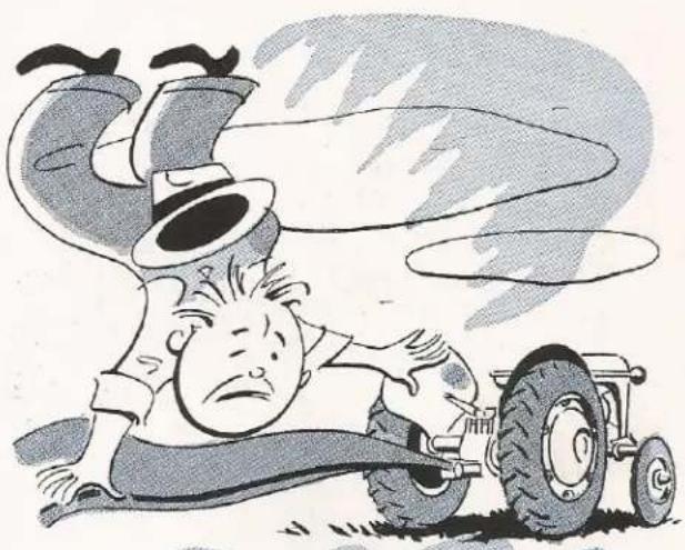
Cartoon illustration of a man in a hat pushing a car tire, with motion blur and smoke effects (no text or symbols)Never put on or remove belt when pulley is in motion.
DETERMINING DIAMETER IN INCHES OF THE DRIVEN PULLEY
| NOTE: This table is based on a 5% slippage loss between the drive and driven pulleys. The smaller the pulley, the greater the amount of slippage involved. Therefore, pulleys smaller than 312" should only be used when absolutely necessary. | ||||||||||||
| Engine R.P.M. | P.T.O. R.P.M. | Pulley R.P.M. | Belt Speed ft./min. | 600 | 800 | R.P.M. Of Driven Pulley | ||||||
| 1000 | 1400 | 1800 | 2200 | 2600 | 3000 | 3400 | ||||||
| 1000 | 364 | 678 | 1560 | 912 | 712 | 6 | 4 | 3 | ||||
| 1200 | 437 | 814 | 1870 | 1112 | 812 | 7 | 5 | 4 | 3 | |||
| 1400 | 509 | 950 | 2182 | 1312 | 10 | 8 | 6 | 412 | 312 | 3 | ||
| 1500 | 545 | 1018 | 2340 | 1412 | 11 | 812 | 6 | 5 | 4 | 312 | 3 | |
| 1600 | 582 | 1087 | 2500 | 1512 | 1112 | 9 | 612 | 5 | 4 | 312 | 3 | |
| 1700 | 618 | 1152 | 2650 | 1612 | 1212 | 10 | 7 | 512 | 412 | 4 | 312 | 3 |
| 1800 | 655 | 1221 | 2810 | 1712 | 13 | 1012 | 712 | 6 | 412 | 4 | 312 | 3 |
| 1900 | 691 | 1290 | 2965 | 1812 | 14 | 11 | 8 | 6 | 5 | 4 | 312 | 3 |
| 2000 | 728 | 1359 | 3120 | 1912 | 1412 | 1112 | 812 | 612 | 512 | 412 | 4 | 312 |
| 2100 | 764 | 1425 | 3280 | 20 | 15 | 12 | 812 | 7 | 512 | 412 | 4 | 312 |
| 2200 | 800 | 1492 | 3430 | 21 | 16 | 13 | 9 | 7 | 6 | 5 | 412 | 4 |
F. ADJUSTING WHEEL TREAD WIDTHS
The advanced development of your Ferguson Tractor makes possible various tread width settings without any unnecessary steps or additional adjustments.
FRONT WHEEL WIDTHS
The front wheels are adjustable in 4" steps from 48 to 80 inches. The steps between 48 and 72 inches
are accomplished by the assembling arrangement of the right and left axle arms on the center axle. To adjust, place the Ferguson Jack in position and raise the tractor off the ground with its own power. Remove the two bolts on each side which hold the axle arms to the center axle. Move the axle arms, in relation to the main axle, to the desired tread width and replace the bolts.
NOTE: Always have one bolt hole between the two bolts to provide a wider support area between the arms and center axle.

natural_image
Front view of a vintage tractor with three large tires and two flanged wheels (no visible text or symbols)76" Wheel Spacing for row-crop work.

natural_image
Close-up of a tractor's front wheel assembly with visible tire and guardrail, no text or symbols presentAdjusting Front Wheels.
With the wheels extended to 72 inch tread width, an additional 8 inches (or 80 inch tread width) can be obtained by reversing the wheel disc on the wheel hub. This places the wheel disc toward the inside. With the wheels in this position, a 76 inch setting can be obtained by moving the axle arms one hole toward the center.
CAUTION: With the wheel discs in the 76 inch or 80 inch settings, the front wheel bearings are subjected to greater strain and load. These tread widths should be used only when absolutely necessary.
NOTE: When 6.00 x 16 inch tires are used, approximately 1 inch wider overall front width in the various positions will be obtained due to the wider tire.

natural_image
Close-up of a person adjusting a large tractor tire, no visible text or symbolsAdjusting Rear Wheels.

REAR WHEEL WIDTHS
To conform with the front wheels, the rear wheels can be adjusted also in 4 inch steps from 48 to 76 inches. Tread width settings are accomplished by changing the relative position of the wheel discs and the rims. The desired wheel settings may be obtained by assembling as shown in the diagram. The tractor as delivered will have a 52 inch wheel setting. The 48 inch wheel setting is obtained by moving the rims in and connecting to the opposite side of the lug. To obtain the 56 inch and 60 inch settings, it will be necessary to reverse the rims on the disc and move the complete wheel assembly to the opposite side of tractor. The 64 inch, 68 inch, 72 inch and 76 inch settings are the reverse of the respective 60, 56, 52 and 48 inch settings, with the wheels on the opposite side of the tractor in each case. The arrow on the side wall of the tire should point in the direction of forward rotation.
G. CARE AND INFLATION OF YOUR TRACTOR TIRES
Correct tire inflation is the most important factor in long tire life. Both under and over inflation have detrimental effects on the casing.
RECOMMENDED TIRE PRESSURE
| FRONT | REAR | ||
| 4.00-19 | 28 lbs. Max. | 10-28 | 12 lbs. Max. |
| *6.00-16 | 28 lbs. Max. | 11-28 | 12 lbs. Max. |
^1 These wheels and tires are also used on the Ferguson Wagon and Belle City Corn Picker.
RESULTS OF UNDER-INFLATION
- Damage to cord body resulting in breakage of cord fabric or side wall.
- Inferior steering and braking control.
- Tire slippage on rim which may tear off valve stem.
- Irregular and uneven tire wear.
- Unnatural tire distortion on hard roads; wiping off tread bar rubber on highly abrasive or unyielding road surfaces.
RESULTS OF OVER-INFLATION
- Excessive tread wear.
-
Loss of traction and increased slippage.
-
Increased packing of the soil; rut formations.
- Casings more susceptible to bruises and impact breaks.
FOR LONGER TIRE LIFE
- Check tire pressure weekly.
- Start and stop smoothly for both tire and fuel economy.
- Avoid excessive slippage which grinds off tread rubber.
- Remove harmful oil and grease promptly from tires.
- Wash tires thoroughly with clear water after spraying and dusting operations (especially when using Paris Green and Bordeaux mixtures which contain injurious copper).
- Keep valve caps tight to prevent air pressure escape. Tighten caps with fingers, not pliers.
- Apply brakes slowly and evenly. Abrupt braking causes wasteful tire wear.
- Allow sufficient clearance between bladed implement edges and tires.
- Don't speed or overload your tires as tractor tires are designed for slow speeds. Towing tractors at high speeds will develop high temperatures and weaken the rubber and cord structure.
- Repair promptly, side wall cuts made by sharp stones, glass or metal.
NOTE: Have your dealer permanently vulcanize casing cuts, bruises, etc.
H. ADDED WEIGHT FOR TRACTION
LIQUID FILL
For some operations, it is desirable to have additional weight to increase traction. The most practical and popular method of adding weight is to liquid fill the tires. This procedure adds weight where it is most beneficial. A calcium chloride solution is better adapted than water because it has a lower freezing point and a higher specific gravity.
It should be pointed out, however, that unnecessary weight causes extra load resulting in higher fuel consumption.
The following table is based on 100% fill in tires using 3½ pounds of calcium chloride per gallon of water. This concentration will have a freezing point
| Size of Tire | Pounds Calcium Chloride | Gal. of Water | Total Weight In Tire |
| 4.00 x 19 | 10 | 3 | 35 |
| 6.00 x 16 | 20 | 6 | 70 |
| 10.00 x 28 | 90 | 26 | 315 |
| 11.00 x 28 | 128 | 36.5 | 450 |
of 30^ below zero. Any other percentage of fill can be obtained by multiplying the percentage times the values given in the table.
Example: If a 75% fill is desired in the 10.00 x 28 tire, the weight of calcium chloride would be 0.75 x 90 or 67½ pounds, the volume of water 0.75 x 26 or 19½ gallons resulting in a total weight of 0.075 x 315 or 236 pounds.
FRONT WHEEL WEIGHTS (Accessory)
When heavy implements are suspended from the rear of your Ferguson Tractor, the weight on the front wheels is reduced, resulting in decreased turning traction. This condition is especially prevalent when crossing headland furrows or ridges such as corn rows, etc., as the bouncing action reduces, even more, the downward action on the front wheels.
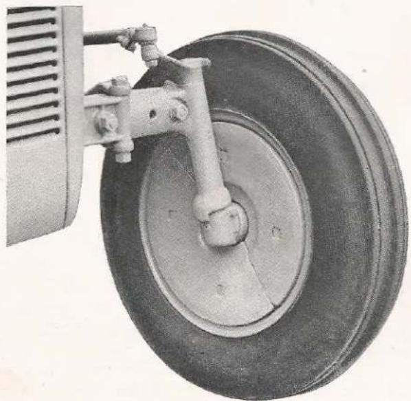
To compensate for this relative reduction in front end weight, the use of front wheel weights is desirable. These weights are easily installed in the dish side of the wheel disc. For the 6.00 x 16 wheel, the weight is in two segments as shown in the illustration. For the 4.00 x 19 wheel, the weight is one piece,
natural_image
Close-up of an aircraft landing gear with a tire and mounted vehicle wheel (no text or symbols visible)Easily installed Wheel Weights.

natural_image
Cartoon illustration of a person riding a heavy tractor through turbulent water, with no visible text or symbols.Never drive too close to ditches or gulleys.
therefore, the wheel will have to be removed before the weight can be installed.
CAUTION: Inspect regularly to see if wheel weights are bolted tight to the wheel discs.
I. STORING YOUR FERGUSON TRACTOR
If your tractor is to be idle for an extended period of time, it should be prepared properly for storage. Have a dry and protected place where it is neither exposed to the weather or livestock.
The following procedure has been outlined for the purpose of keeping your Ferguson Tractor in working condition for many seasons:
- Thoroughly wash and clean tractor.
- Remove all rust spots with sandpaper and repaint.
- Remove air cleaner. Wash filter and inside of cleaner thoroughly with gasoline. Refill cup with new oil and reinstall.
- Lubricate all pressure fittings. Drain crankcase and oil filter element.
- Install new oil filter element and refill crankcase with recommended grade of oil.
- Drain transmission and refill with proper grade of new oil.
- Clean and repack front wheel bearings.
- Check oil level in steering gear.
- Start engine and run to lubricate engine parts until temperature stabilizes.
- Inspect tractor for worn or damaged parts which later may cause costly breakdowns. Order any

natural_image
Cartoon illustration of a man celebrating with arms outstretched, chasing a tractor in motion (no text or symbols)Always stop tractor before dismounting.
needed items from your Ferguson Dealer promptly while the need is still in your mind.
- Completely drain cooling system, thoroughly washing and flushing out with washing soda and water. See page 23. Replace cap and close drain-cocks when dry to keep system clean.
- Drain fuel tank by removing filter assembly and let dry. Replace cap and filter to keep tank clean.
- Remove, clean and replace sediment bulb, gas line and carburetor.
- Remove spark plugs and pour two tablespoons of heavy lubricating oil into each cylinder top.
-
Clean and regap spark plugs at 0.025".
-
Turn engine over several revolutions before replacing spark plugs using crank or starter.
- Cover ends of exhaust pipe and breather pipe.
- Remove, inspect and condition battery as required, then store in a cool place. Keep battery in a fully charged state. Inspect every two weeks to assure charge is correct.
- Jack up tractor and put on sturdy blocks to remove weight from tires.
- Remove water from tires to prevent freezing.
- Cover tractor with tarpaulin for protection (a special storm cover for the engine is available at your Ferguson Dealer).
STARTING ENGINES THAT HAVE BEEN IN STORAGE
- Remove spark plugs and pour two tablespoons of a mixture of one-half gasoline and one-half light lubricating oil into each cylinder.
- Reinstall spark plugs.
- Install fully charged battery making sure the proper connections are made. The Ferguson Battery is positive grounded.
- Fill the cooling system with proper coolant.
- Fill the fuel tank.
- Check oil level in crankcase, transmission and air cleaner.
- Remove coverings from exhaust and breather pipes.
- Inspect and tighten all nuts, bolts and screws.
- Lubricate all fittings.
- Start engine and allow it to run at an idle speed for 10 to 15 minutes. Note oil gauge to be sure the engine is receiving proper lubrication.
- Drive the tractor without load and at slow speeds noting its operation.

natural_image
Illustration of a tractor in front of a barn with a barn and a dog, no text or symbols presentYour Ferguson Dealer has this Storm Cover and other Accessories.
servicing your tractor
While we recommend that major overhauls, replacements and adjustments be done by the Ferguson Dealer whenever possible, occasions may warrant the owner making minor repairs and adjustments. For that reason, the following material has been compiled to give you a working knowledge of your Ferguson Tractor.

CROSS SECTION CUT-AWAY OF THE FERGUSON TRACTOR
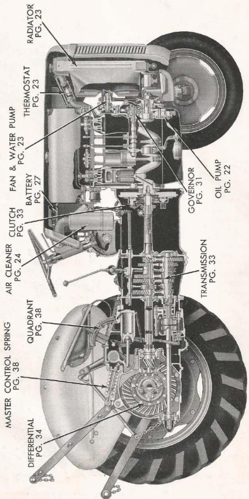
SERVICING YOUR TRACTOR
A. YOUR FERGUSON ENGINE
The engine of your Ferguson Tractor has been developed especially for the type of tractor which integrates an hydraulic system to operate and control attached implements. The engine is a four stroke cycle, four cylinder, wet sleeve, valve-in-head unit with a cylinder bore of 3 14 " and a piston stroke of 3 18 ". It has a total displacement of 129 cubic inches and a compression ratio 6.5 to 1. The valve-in-head characteristics provide steady lugging power at lower engine r.p.m.'s with more economical operation, thus supplying the ideal features wanted for tractor work. Positive acting rotating type exhaust valves are included as standard equipment insuring long valve life and more efficient performance.
1. OILING SYSTEM
The crankcase capacity is 5 U.S. quarts with the oil pumped under pressure to all bearing surfaces in the engine. Oil is drawn by the pump, from the pan, into the oil intake float suspended above the bottom of the pan. This then allows only clean oil to pass into the system. The pump forces the oil under pressure to the front main bearing and to the oil galley which runs the length of the block. From the front main bearing, oil passes through the drilled crankshaft to the front connecting rod bearing and also to the front camshaft bearing which meters it through the camshaft retaining plate to the governor and timing gears. The oil galley supplies the center crankshaft bearing which in turn furnishes the center camshaft bearing and the second and third connecting rod bearings through the drilled crankshaft. The main galley also supplies the metering passage to the filter element, and the rear main bearing which in turn supplies the rear camshaft bearing. Oil from the rear camshaft bearing is metered through a passage to the rear support of the rocker arm shaft. This pro-

Front end view of Engine Oiling System showing filtering action.

natural_image
Cross-sectional technical illustration of a mechanical assembly (no visible text or labels)Side view of Ferguson Engine with pressure oil path to all bearing surfaces.
vides lubrication for the rocker arm bushings and valves. The oil returns through the push rod holes lubricating the tappets and cams.
The engine is ventilated through a breather tube bolted to the left side of the valve cover. This tube should be removed and cleaned occasionally, removing the dirt and dust restrictions.
OIL PUMP
A single stage, gear type oil pump located beneath the front main bearing, pumps oil from the pan to the oil passages. A relief valve in the pump body by-passes oil if the pressure exceeds 30 pounds.
OIL FILTER
The oil filter located on the right side of the tractor engine is integrated with the block in that no external oil lines are used. This arrangement greatly increases the efficiency of the filtering as the operation is performed at engine oil temperature. The flow of oil is from the outside toward the center of the filter, thereby, causing the external surface area of the element to first come in contact with the oil. The function of the oil filter is to remove sludge, grit, carbon, metal particles, etc., from the oil system. This is a continual process which is performed while the engine is operating. As the filter element becomes loaded or saturated with foreign material from the oil, it ceases to function and filter properly. Therefore, it should be removed and replaced at recommended intervals.
CHANGING CRANKCASE OIL AND FILTER ELEMENT
The oil in the crankcase as delivered to you is break-in oil and it should be drained and the crankcase refilled with proper lubricant after the first 50 hours of operation. Thereafter, the oil should be changed every 100 hours. Adverse working conditions such as severe dust or extremely cold weather may necessitate more frequent changes. Flushing the crankcase with oils or solutions, other than a good winter grade engine oil, is not recommended. If flushing is necessary, use 3 quarts of 10 W oil and run at a fast idle for a few minutes. Drain immediately and fill with the correct seasonal grade of engine oil. For most operating conditions a Regular Grade engine oil is satisfactory. Premium and heavy duty oils contain detergents which hold carbon and other foreign particles in suspension until the particles are removed by the filter. The premium and heavy duty

natural_image
Close-up of a mechanical component with a metallic cylindrical part inserted, showing internal components and a small hole (no visible text or symbols)Removing the Oil Filter Element.
grades, therefore, offer advantages not obtained with the regular grade oils.
NOTE: It is essential that the crankcase be drained when the engine is warm as the foreign material is in suspension and will flow out with the oil.
The filter element should be replaced with a new Ferguson Filter every other oil change and the inside of the case wiped out. To change the filter element, remove the cap by turning out the center bolt and pull out element using the attached ring.
NOTE: When a new filter element is installed, one quart extra oil should be added to allow for element absorption.
2. COOLING SYSTEM
The cooling system of your Ferguson Tractor consists of a radiator, pressure type radiator cap, fan, water pump, thermostat and 10 quarts of coolant. The coolant conducts heat from around the wet sleeves and circulates through the radiator where the heat is transferred by the copper fins to the forced air passing through the radiator. The cooling system incorporates a recirculating passage which

allows faster and more even warm-ups by bypassing a metered amount of the coolant through the water pump back into the block before the thermostat opens.
RADIATOR
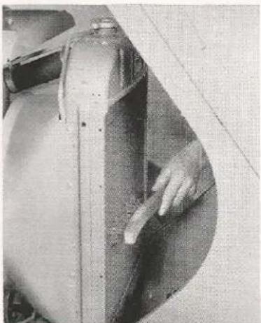
The radiator is a copper tube and fin type with coolant entering the top and passing down through the tubes to the bottom. For efficient cooling, the fins must be kept clean of all lint, weeds and other foreign material. A clogged condition is sometimes only apparent by looking through the fins and remedied by blowing out with water or air pressure.
natural_image
Close-up of a hand interacting with a mechanical component, possibly a valve or valve assembly (no visible text or symbols)Cleaning the Radiator of all foreign material such as dirt, lint or bugs.
RADIATOR CAP
A pressure type cap permitting 6 to 8 pounds per square inch of pressure to build up within the cooling system raises the boiling point of the coolant 18^ to 24^ . It is essential that the pressure cap be used and installed tightly at all times.
CAUTION: Remove radiator cap slowly and carefully by turning to the first notch. This relieves the pressure, preventing injury from escaping steam and scalding water. Always remove the pressure cap when draining the cooling system, otherwise all the coolant will not drain out.
FAN AND WATER PUMP
A four blade pull-type fan, mounted on the water pump pulley, draws air through the radiator and blows it around the engine. The impeller type water pump circulates 32 gallons per minute at 2,000 r.p.m. The fan belt drives both fan and water pump. These are supported by a prelubricated sealed bearing which needs no additional lubrication.
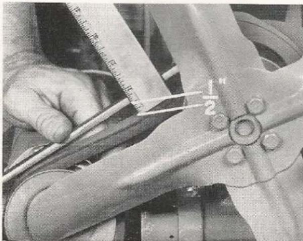
NOTE: The fan belt must have sufficient tension to properly turn pulleys, but not excessive to cause bearing wear. See page 30.

natural_image
Cartoon illustration of a person in uniform looking through a device with a cloud-shaped head, surrounded by a starburst background (no text or symbols)Use caution when removing pressure cap from radiator.
THERMOSTAT AND HOSES
The thermostat is located in the top radiator hose with the expansion coils nearest the engine. It begins to open at 157° F. to 162° F. and is fully open at 185° F. to 195° F. An inoperative thermostat, or one removed from the system, will cause improper warm-up and operating temperatures, resulting in excess condensation and crankcase dilution. Hoses should be inspected occasionally for leaks and clamps tightened when necessary.
NOTE: If during cold weather, the tractor is used for long periods under heavy loads, a permanent type antifreeze should be used.
CARE OF COOLING SYSTEM
Soft water or rain water should always be used in the cooling system. Hard water contains alkalies,
natural_image
Person inspecting a large industrial heat exchanger component with circular annotations highlighting parts (no visible text or symbols)Open the two Drain Cocks and remove Pressure Cap when draining Radiator.
acids, salts and other impurities which hasten rust and scale formation. This process is also speeded up by the heat generated in the engine. Clean and flush the cooling system twice a year, preferably in the Fall before the addition of an antifreeze and in the Spring when it is removed. To prevent corrosive action in the cooling system, use a reliable rust inhibitor after flushing.
of gasoline. It is, therefore, essential that the air cleaner be kept clean. A partially plugged air cleaner results in a power loss and increases fuel consumption. Clean and refill the oil cup each day using the same weight oil as is used in the crankcase. In extreme dirty and dusty conditions, it may be necessary to follow this procedure twice a day. Clean the intake screen on the instrument panel when dirty,
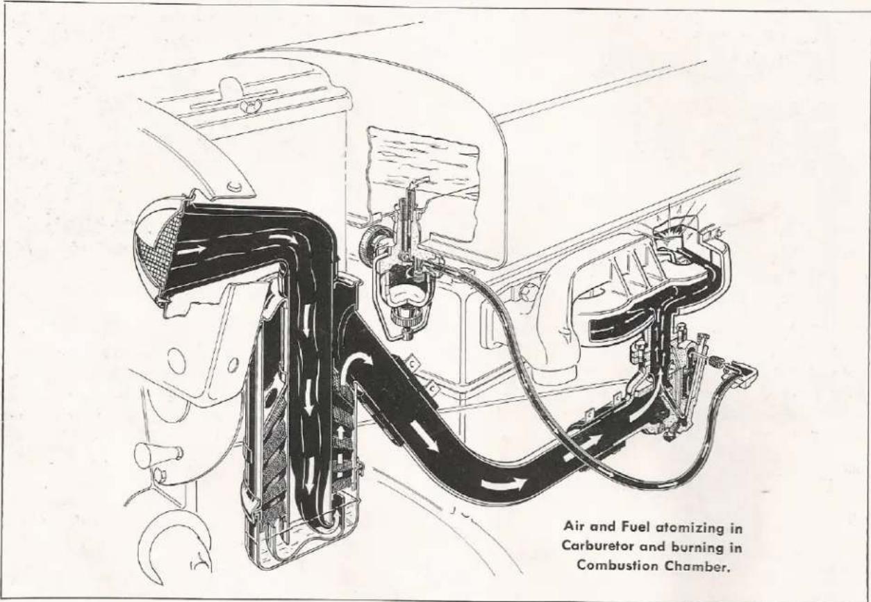
3. AIR AND FUEL SYSTEM
Your tractor air and fuel system consists of an air cleaner, filter and sediment bowl, carburetor and gasoline tank.
AIR CLEANER
The air cleaner located behind the instrument panel adjacent to the right side of the battery, filters the air entering the carburetor. Foreign material such as dirt and other abrasives, if allowed access to the engine, will cause excessive wear of cylinders, pistons, rings and valves.
Care of the Air Cleaner
Approximately 9,000 gallons of air must pass through the air cleaner to efficiently burn one gallon but never oil this screen as dust would adhere and reduce the air flow.

natural_image
Close-up of industrial machinery components with no visible text or symbolsRemove Inlet Screen to clean.
natural_image
Person operating a mechanical device with a bucket and pipe (no visible text or symbols)Air Cleaner Oil Bath.

natural_image
Cartoon illustration of a person falling off from a tractor with flying chickens and a cloud, no text or symbols presentDon't smoke when refueling or inspecting gasoline tank.
The internal filter is cleaned by removing the air cleaner and rinsing the assembly in gasoline. This procedure should be done once or twice a year. Under some conditions, the filter becomes so plugged with dirt and lint that washing in gasoline will not remove this clogged condition. If this occurs the air cleaner will have to be replaced.
NOTE: Periodically, the entire air cleaner and hoses should be thoroughly inspected for cracks and other openings which would allow unfiltered air to enter the carburetor.
FUEL FILTER AND SEDIMENT BOWL
The fuel filter and sediment bowl assembly is located below and to the rear left side of the fuel tank. This assembly incorporates a shut-off valve which stops gasoline flow and controls the main and reserve fuel supplies.
To select the closed, main, or reserve fuel supply position, the shut-off or control knob is turned as follows. Turn the control knob fully to the right (clockwise) to shut off fuel supply. Turn the knob left (counterclockwise) two turns from the closed position to open the main fuel supply. Turn the knob fully to the left to open the reserve supply. The main fuel supply flows through a standpipe which extends above the bottom of the tank. The inlet for the reserve supply is nearer to the bottom of the tank. Do not allow the reserve supply to go unused for long periods as condensation and rust may collect. It is desirable to operate the tractor an hour each day on reserve supply.
Care of Fuel Filter and Sediment Bowl
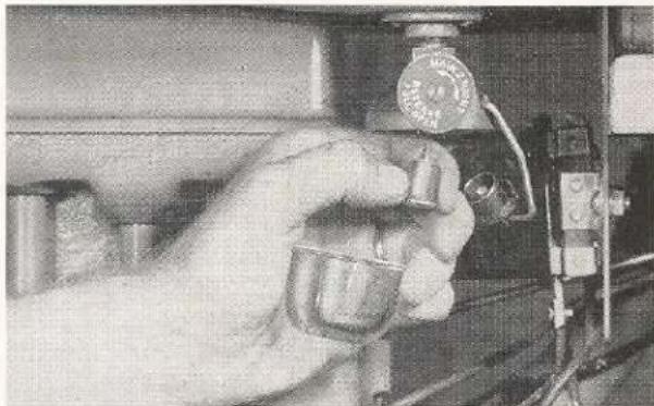
The fuel filter and sediment bowl filters the gasoline and provides a sediment basin for the fuel as it leaves the tank. Each week the filter and the bowl
natural_image
Close-up of a hand holding a small mechanical component, possibly a valve or knob, with wiring visible (no text or symbols)Removing Sediment Bowl and Disc Filter.
should be removed, cleaned in gasoline and reinstalled. Periodically, the disc filter should be soaked and washed in a varnish solvent to remove the varnish deposited by the fuel. (Cities Service number 26 cleaner, paint remover or equivalent). Use only in well ventilated areas. When replacing, tighten disc filter finger tight. Do not use pliers.
For safe, trouble free operation, the fuel tank should be flushed in the Spring and Fall. This is accomplished by removing the fuel filter assembly from the tank and flushing with gasoline until all rust and water is removed.
CARBURETOR
The balanced, up-draft type carburetor is fully sealed against the entrance of all dust and dirt. A porous plug is incorporated in the bottom of the carburetor to allow manifold condensation and excess fuel to escape, yet it prohibits the entry of dust and dirt. A screen in the fuel line inlet elbow strains all fuel entering the carburetor.
Carburetor Adjustments
The operator of any tractor must realize that the amount of fuel a tractor uses when working depends upon many factors, some of which are:
-
Proper adjustment of the tractor electrical system.
-
Care previously given the tractor.
- Internal condition of tractor, such as valves, rings, pistons, bearings, etc.
- Operator's method of handling tractor.
- Type of implement being operated.
- Adjustment of implement.
- Type and condition of soil.
- Depth of operation of implement.
However, it should be kept in mind that fuel consumption is proportional to the amount and rate of work done. Therefore, fuel consumption comparisons should be made on an acre per hour basis instead of just acres of work done.
The most efficient performance is obtained when the tractor and implement are operated under the most favorable conditions by an experienced operator.
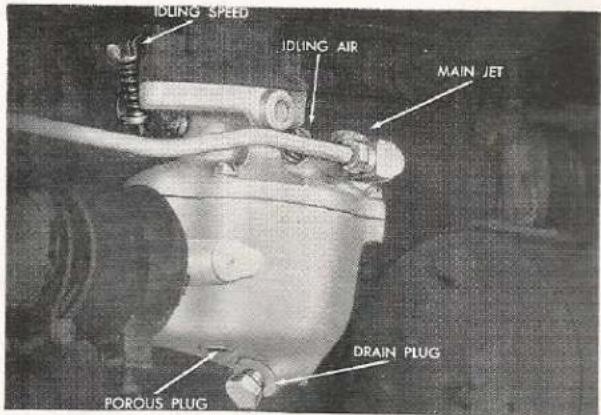
The carburetor incorporates both idle and main fuel passages with corresponding adjustments which are sufficient to provide the correct fuel and air mixture from idling to top governed speed and from no load to full load.
IDLING AIR
The idling air adjustment regulates the flow of air while the engine is idling. Turn out screw 18 of a turn from closed position or until the engine idles smoothly when warm.
IDLING SPEED
An adjusting screw on the throttle shaft arm regulates the minimum idle speed. Turn the screw in to increase, or out to reduce speed.
MAIN JET
Adjust main jet by turning in needle valve to fully closed position (not tight), then backing off one and one quarter (114) turns for the approximate operating setting. When the engine is warm the final adjustment should be made so it runs smoothly according to the load.
IMPORTANT: An excessively lean mixture reduces power, overheats the engine and may cause burnt valves. Therefore, the main jet should never be set less than 1 turn open. A mixture which is too rich wastes fuel and causes uneven operation. Field test the tractor under normal load by quickly moving the throttle from half open to fully open position. If engine coughs and stalls, open main jet 1/16 turn and repeat test. Repeat this procedure until engine responds immediately to increased acceleration and runs smoothly and evenly.
Carburetor Adjustments.
NOTE: The carburetor has been designed and calibrated scientifically for the most efficient and economical operation of the engine. Therefore, any changes or improper adjustments subjected to it can result in unsatisfactory performance or possible damage to the engine.
Draining Carburetor
At the bottom of the carburetor is a drain plug which permits draining the carburetor to remove dirt and water.
The carburetor should be drained each week or according to the circumstances and conditions prevailing. Remove drain plug and permit gasoline to flush carburetor. Never attempt to blow out carburetor through gasoline inlet elbow and strainer screen, as the screen may be ruptured and dirt blown into the carburetor. Remove and clean inlet strainer screen twice a year as a restriction at this point may cause reduced fuel flow.
NOTE: When removing and replacing the elbow strainer, thread a fitting into the elbow to prevent the wrench from collapsing the elbow.
Store Your Fuel Properly
Fuel should be stored in a cool, dry place, preferably in an underground tank. If this is not practical, keep it in clean, dry drums, protected from the direct rays of the sun. The highly volatile parts of the fuel, which contribute to easy starting and high antiknock value, evaporate rapidly if exposed to heat.
Heat also hastens gum formation. Excessive gum in the gasoline may cause sticky intake valves; a clogged carburetor, fuel filter, and manifold.
The electrical system of your Ferguson Tractor consists of a battery, starting motor, starter switch, regulator, ammeter, ignition switch, coil, distributor, spark plugs and wiring. The purpose of the electrical system is to make available electric current for ignition, starting and other needs such as lights, etc. This battery-ignition type electrical system uses a storage battery to provide the primary or initial source of energy for ignition in the combustion chamber. This battery or low tension current is converted by the coil and distributor breaker points to a high voltage surge which jumps the spark plug gap in the combustion chamber. The generator, with related parts, generates an electrical current, controls it so that it will maintain the storage battery in a charged condition and supplies sufficient current for the normal electrical load of the tractor.

natural_image
Technical line drawing of a mechanical assembly with labeled components (no readable text or symbols)Pictorial diagram of Ferguson Electrical System.
BATTERY
The Ferguson Battery is a 13 plate, 6 volt, 80 ampere-hour capacity battery. The performance obtained from your battery depends on its amount of charge and the condition of the engine, starting motor and wiring. Cold weather reduces battery efficiency by retarding electro-chemical action. A fully charged battery with 100% cranking power at 80° Fahrenheit will drop to 2/5 of its original cranking power at 0° Fahrenheit. An engine also requires 2½ times more cranking effort at 0° Fahrenheit than at 80° Fahrenheit. Therefore, during cold weather, the battery should be in the best possible condition. The battery should be periodically inspected for the following:

Battery Non-Overfill Washers.
- Battery surface condition, cable corrosion and frayed cables. Clean by washing with warm baking soda solution. After connecting cable terminals to battery posts, coat with light grease to prevent corrosion.
NOTE: Care must be exercised not to get soda solution in vent holes as a neutralization of the electrolyte will result. Frayed cables should be replaced as excess resistance or shorts may develop.
2. Cracked or broken case.
-
Soft sealing compound. This condition is usually caused by over-heating due to over-charging and will shorten battery life.
-
Battery Carrier. The wing nuts should be finger tight. Over tightening will cause case distortion when battery becomes hot. A loose battery will vibrate which may cause breakage.

natural_image
Cartoon illustration of a person blowing smoke from a car, with steam rising (no text or symbols)Keep flames away from battery filter cap openings.
- Battery Caps. A broken or missing cap permits dust and dirt to enter the cell, shortening battery life. A plugged cap will not allow battery gases to escape, thereby damaging separators.
- Solution Level. The level should be inspected once or twice a month to make sure it is approximately 38 " above the plates.
Steps in filling battery.
a. Remove cap.
b. Fill cell with syringe to top of filler well without touching non-overfill washer.
c. Replace cap.
NOTE: Replacing cap will move non-overfill washer, permitting trapped air to escape, and electrolyte level will fall to bottom or slightly below filler well.
- Specific Gravity. The specific gravity of a battery indicates the chemical condition of the battery. However, this is only true if the level is 38'' above the plates. The specific gravity of a fully charged battery will be 1.280 or greater. A period of four hours should elapse before checking specific gravity after adding water to permit the solution to become uniform. If the battery has a low specific gravity reading, the battery should be recharged.
NOTE: Except in cases of emergency, a battery should always be slow charged to obtain long battery life.
CAUTION: A battery produces and gives off very explosive hydrogen gas. It is important then, that flames or sparks be kept away from the vent openings.
DISTRIBUTOR
The distributor is fully automatic and is protected from the dust by a special seal between the cap and housing and by rubber caps over the entrance of the high tension wires. These rubber caps also prevent the entrance of moisture. It is essential for optimum operation that the distributor be in proper working condition at all times as it performs the following functions:
- Opens and closes the low tension circuit (distributor breaker points) providing the coil with surges of current.
- Times these surges to the engine speed with the centrifugal advance mechanism.
- Directs the coil high voltage surges to the correct spark plug at the correct time.
Distributor Inspection and Servicing
The following inspection should be performed at regular intervals to insure that the distributor mechanism is clean and functioning properly.
- Remove distributor cap, rotor and dust cover. Note the condition of (a) contact points and (b) rotor and cap.
a. The contact points should meet squarely and have the proper gap (0.022"). With old worn points, it is difficult to obtain the correct gap setting by using a feeler gauge as the gauge only measures between the high points on the jagged surface. If a build-up is apparent on the points, the surface can be squared up by a few strokes of a fine cut file. To adjust points, crank engine until point wearing block is on a cam lobe (points are then open fully). Loosen lock screw and turn eccentric screw until correct opening is obtained. Tighten lock screw and recheck point opening.
b. Carbonized or chipped rotor and cap will cause high tension leakage to ground. If this condition exists, the parts should be replaced.
- Check distributor cap and high tension wiring for frayed or damaged insulation. Check connections

Distributor Points fully open.
at the distributor cap and plugs. Excess resistance in the wires or frayed wiring may cause leaks to ground.
3. The distributor has a built-in oil reservoir filled with light engine oil and sealed at the factory. Under normal operating conditions, the reservoir should be refilled every
750 hours of operation (more frequent refilling is required when unusual heat or other abnormal operating conditions are encountered). To refill reservoir, remove oil plug and add 20W oil.
A small trace of cup grease should be placed on the breaker cam every 100 hours of operation. Also place 1 or 2 drops of light (10W) engine oil on the breaker lever pivot and 3 to 4 drops on the felt wick under the rotor.
NOTE: Avoid excessive lubrication, as too much oil will get on the contact points and cause them to burn.
Engine Timing
A properly advancing distributor cannot provide correct ignition unless it is timed to the engine. For correct spark delivery with engine not running, points should open 6 degrees before top dead center on compression stroke.
To Time Engine
- Remove No. 1 spark plug and crank engine until compression stroke creates pressure on finger held in spark plug hole.
- Remove timing hole button plug and crank slowly until graduated lines on front of the flywheel can be seen. When the line indicating 6 degrees (before top dead center) is aligned with groove in timing hole, the breaker points should then be starting to open. If they are not, then loosen distributor clamp screw

natural_image
Close-up of a hand using a tool to measure a circular gauge or dial, with no visible text or symbols.Flywheel timing marks.
and slowly rotate complete distributor until points just break contact.
NOTE: It is recommended that the engine be timed with a timing light by your Ferguson Dealer. With this method of timing, the maximum advance at 1,500 and 2,000 r.p.m. should be 23° and 32° respectively.
IGNITION COIL
The coil is oil filled to permit more rapid heat dissipation and provide greater insulation, and is hermetically sealed against the entrance of air and moisture. A bakelite insulator, which resists surface leakage, protects the high tension terminal. Always make sure all leads have tight connections as excessive resistance will reduce the efficiency of the coil output.
GENERATOR
Your Ferguson Tractor Generator is a 6 volt unit having an adjustable third brush to control its output. Moving the adjustable brush in the direction of rotation increases the output. Generator output must be set using external meters; it cannot be measured with the tractor ammeter. The generator is capable of a continuous output of 16 to 19 amps under normal operating conditions. The generator is driven by the fan belt with the pulley end of the armature supported by a ball bearing and the commutator end by a bronze bushing.
Generator Servicing
Lubricate hinge-cap oilers every 100 hours of operation with medium weight engine oil.
CAUTION: Avoid excessive lubrication as overoiling may force lubricant out on the commutator which will result in reduced generator output and increased commutator and brush wear. Never lubricate the commutator and do not lubricate the generator while it is in operation.
Occasionally observe the condition of the commutator and brushes by removing the cover band. If the commutator is dirty, it may be cleaned by holding a strip of No. 00 sandpaper (never use emery cloth) against it with a wood stick while the generator is operating. Move the stick across the length of the commutator to insure even cleaning. All dust should be blown from the generator after the commutator is cleaned.
NOTE: If the commutator is rough, out of round, or has high mica, see your Ferguson Dealer. If the brushes are worn down to less than half their regular length they should be replaced.

A hinge type of mounting and slotted bracket at the driving end allows for fan belt tension adjustment. To adjust, loosen the bracket and pivoting bolts and pivot generator. Tighten bolts thoroughly.
natural_image
Close-up of hands using a tool to cut metal parts with a ruler and screw hole (no visible text or symbols)Fan Belt Tension.
STARTING MOTOR
The starting motor is a 6 volt, 4 pole, 4 brush, series wound motor, mounted on the engine flange of the flywheel housing. The armature rotates in oilless bushings. The Bendix drive engages the pinion to the ring gear on the flywheel when the armature rotates. The over running effect of the engine on the pinion disengages the pinion from the flywheel ring gear when the engine starts. The starting motor is operated by the gear shift lever. To start the engine, raise the shift lever, at the same time moving it to the right and forward toward the raised letter "S" on the transmission cover.
Periodic cleaning of the commutator should be the only servicing needed. (See page 29 under Generator Servicing.) In case of functional difficulty, the starter should be removed and taken to your Ferguson Dealer.
CAUTION: Never operate the starting motor for periods longer than 30 seconds, without pausing for a few minutes to allow the starting motor to cool, otherwise the commutator bars may come unsoldered.
GENERATOR REGULATOR
The generator regulator is a combination current-voltage regulator and cutout relay to control the direction of current and generator output according to the battery condition and electrical load. The regulator should be serviced and adjusted only by a competent mechanic as maladjustment can mean a burned out regulator or generator
SPARK PLUGS
Examine spark plugs frequently for excessive carbon deposits, pitted or burned electrodes, broken porcelain and blow-by marks. Faulty spark plugs can be a major cause of poor engine performance. Therefore, when servicing, either clean and adjust, or replace if defective. For best engine performance clean and gap plugs every 100 hours of operation. Plugs should be cleaned with a sand blast machine and regapped at 0.025" with a wire feeler gauge (see your Ferguson Dealer). When the tractor is operated, intermittently, under light loads in cold weather, a hotter than normal heat range plug is needed. When the tractor is operated under heavy loads above average needs during hot weather, a colder than normal heat range is needed.
Recommended 18mm plugs for the Ferguson TO-30 Tractor are:
| MAKE OF PLUG | HEAT RANGE | ||
| Standard | Hot | Cold | |
| Champion | 8 Com. | C-7 | 6 M |
| A C | 86 Com. | 87 Com. | 85 Com. |
5. VALVE ADJUSTMENT
Proper valve adjustment is essential for quiet, smooth operation and long valve life. However, it should be noted that quiet valves may mean tight valves. If this condition exists, short valve life will result due to the valves burning. The following procedure for adjusting valves is recommended.
- Remove gas tank and cylinder head cover.
- Crank engine with starter until one valve on No. 1 cylinder is open. (This valve spring will be completely compressed.) Set other (or closed) valve at 0.013". Crank engine until other valve opens on No. 1 cylinder and set other (or closed) valve at 0.013".
- Repeat this procedure with other three cylinders.
- Set both exhaust and intake valves at 0.013".
- Recheck valves with engine at operating temperature and running at slow idle, using a 0.013" feeler gauge and readjust if necessary.
NOTE: If an auxiliary gasoline tank is used, valves can be set hot without following steps 1 through 4.

natural_image
Close-up of hands using a screwdriver to adjust or install components on an engine cylinder (no text or symbols visible)Adjusting the Valves.
6. GOVERNOR
An improved type, variable-speed, centrifugal governor with ten evenly spaced ball weights held in a metal retainer attached to the cam shaft gear regulates the engine speed as the load varies. The governor mechanism is completely enclosed by the timing gear housing except for the control linkage. By use of the hand throttle, a selection of engine speeds from 400 to 2,200 r.p.m. can be obtained. Also any selected speed between 1,000 and 2,200 r.p.m. can be maintained even though the load may vary.
Opening the hand throttle increases the governor spring tension. This causes the governor linkage to overcome the force of the ball weights, thereby opening the carburetor throttle butterfly and permitting a greater amount of fuel mixture to enter the cylinder which increases the engine speed. The increase in speed gives greater force to the governor's ball weights, which begin to overcome the spring tension and partially closes the throttle butterfly. A balance is reached between the action of the ball weights and the spring tension, and is maintained until either the load or position of the hand throttle is changed.
When the hand throttle is set for a certain speed and the load increases, there is a tendency to reduce the relative force of the governor ball weights, thereby permitting the spring tension to open the throttle butterfly, compensating for the increased load. Exactly the opposite condition occurs if the load is decreased.
The governor is lubricated by engine oil, which is forced through the bleeder holes from the front camshaft bearing. Proper governor action must be obtained to have steady and efficient lugging power as any binding or maladjustment will result in faulty or erratic operation.
To check governor action:
-
Start engine (must be at operating temperature).
-
Set hand throttle for 1,000-1,200 r.p.m. (Half throttle.) Use hand tachometer or chart on page 33. Engine should be "revved-up" then reduced to desired r.p.m.
-
Set master brake.
-
Shift to 4th gear.
-
Release clutch gradually.
-
Observe if governor lever pulls throttle rod quickly forward without delay. If it does not, note to see if bumper screw is backed away from bumper spring. This is accomplished by backing screw out about one turn from the spring.
-
Recheck operation procedure 1 through 5, if insufficient action is still present, check external governor linkage for binding and proper geometry as described below.
GOVERNOR ADJUSTMENT
If governor action is responsive, check top speed as follows:
Open hand throttle fully and note top speed. Top speed should be 2,100-2,200 r.p.m. If not, loosen U-bolt and turn assembly on torque rod until correct speed is obtained. If surging is experienced, the bumper screw will have to be turned in until it touches the bumper spring.
CAUTION: Do not turn bumper screw in any farther than necessary to stop surging as it deadens governor action at slow speeds.

Observing Governor Operation.
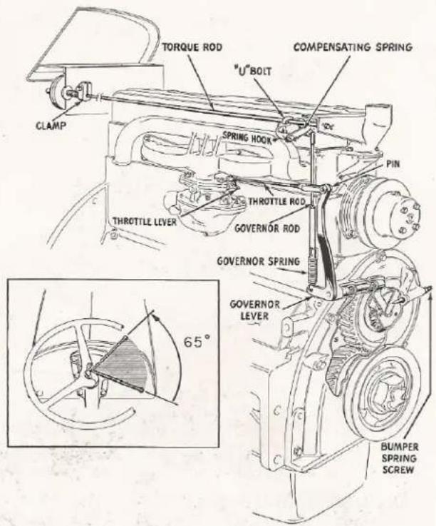
Governor Linkage.
NOTE: Surging is the result of either wear or binding. Therefore, to obtain efficient operation, the cause of surging should be determined and eliminated.
To check exterior governor linkage for binding, open and close hand throttle and note the following points and correct if necessary:
- Governor spring and engine block. Move the U-bolt assembly forward on torque rod, being careful not to have interference between compensating spring and water outlet elbow housing.
- Throttle rod and governor plate. Place the tractor wrench against the bottom of the vertical part of the governor lever arm and bend it outward until binding is eliminated.
- Vertical arm of governor lever and fan belt. The throttle rod should be shortened to prevent interference.
- Governor lever shaft and front cover housing. Remove governor spring from governor rod slot and move lever back and forth to check for binding. Binding will be due to dirt or a damaged shaft. The latter will require removing the front cover to correct.
- Compensating spring or top of governor rod and water outlet below housing. Move U-bolt assembly back on torque rod until binding is eliminated. Recheck step (1).
-
Throttle rod clevis pin and governor arm. Loosen locknut and retighten, holding clevis in a position where no binding occurs.
-
Cotter pin on carburetor end of throttle rod and throttle lever assembly. Cotter pin should be installed from the top of the throttle rod with the pin wrapped neatly around the throttle rod.
Before checking linkage for length, check engine idling speed:
- Disconnect throttle rod from governor lever.
- Start engine.
CAUTION: Care should be taken to hold throttle rod in an idle position when starting engine. If this precaution is not taken, the engine will speed beyond its normal maximum engine r.p.m.
3. Hold throttle rod against idling stop and adjust idling speed screw until 400-450 engine r.p.m. is obtained.
To adjust throttle rod length:
- Open hand throttle fully to create tension on governor spring.
- Adjust throttle rod length until it is necessary to move the rod back slightly ( 12 " or less) in order to insert the pin through the throttle rod clevis and governor lever.
- Lock clevis in position. Make sure pin fits freely and that clevis does not bind against governor lever.
NOTE: If governor arm interferes with the fan belt, shorten the throttle rod.
To adjust governor rod length:
- Place hand throttle lever at idling position, i.e. about 65° forward from the "full-open" position against the steering wheel.
- Observe if governor compensating spring link is touching the torque rod. If not, loosen U-bolt assembly and rotate on torque rod. Retighten U-bolt.
- Observe if governor rod is long enough to contact horizontal arm of governor lever and hold throttle against idle stop. If not, loosen locknut on governor rod, remove governor spring and adjust rod until it lightly touches the arm of the governor lever and holds it at the "idle" position.
Reconnect spring and retighten locknut.
4. Recheck top engine speed, if not 2,100 to 2,200 r.p.m., loosen U-bolt on torque rod and adjust.
To remove Hand Throttle Creep:
- Increase spring compression on friction disc under dashboard. If this does not remove creep, replace friction disc.
NOTE: Care must be taken not to position clamp where it will strike the battery. - Shorten compensating spring.
To correct Hand Throttle Arc:
-
Remove governor spring and shorten rounded end.
-
If step 1 did not correct, replace spring.
To check engine speeds without a tachometer or revolution counter, jack one rear wheel up off the ground, place a mark on the tire and count revolutions per minute, running in first gear.
CHECKING ENGINE SPEEDS
| With aRear WheelR.P.M. of | THE CORRESPONDING | ||
| EngineR.P.M.is | P.T.O.ShaftR.P.M. is | PulleyR.P.M.is | |
| 10 | 400 | 145 | 270 |
| 1212 | 500 | 181 | 338 |
| 2512 | 1000 | 363 | 676 |
| 38 | 1500 | 543 | 1014 |
| 51 | 2000 | 727 | 1358 |
| 56 | 2200 | 800 | 1493 |
B. TRANSMISSION AND CLUTCH
1. TRANSMISSION
The Ferguson Transmission has constant mesh, helical cut gears with sliding shifter collars insuring quiet operation and effortless shifting.
The heavy forged shifter forks provide positive movement of the shift collars when the shift rails are moved. Detent pins, located in notches in the shift rails, control the position of the rails in neutral or in gear. Two balls and one pin arranged in the rear flange of the transmission housing between the shift rails act as a safety device. When one rail moves, the balls are pressed into the notches in the other two rails, making it impossible to engage two gears at the same time.
There are four speeds forward and one reverse.


natural_image
Cross-sectional technical illustration of a mechanical assembly (no visible text or labels)The Ferguson Transmission.
2. CLUTCH
The clutch is a single plate dry disc type. Adequate clearance between clutch plate release fingers and clutch release bearing is essential to insure efficient operation. This is adjustable and is evident in the clutch pedal free play. To adjust clutch pedal, loosen clamp bolt and
GROUND SPEEDS IN MILES PER HOUR
| 10.00 x 28 Tire | 11.00 x 28 Tire | ||||||
| Gear | 1000 RPM | 1500 RPM | 2000 RPM | Gear | 1000 RPM | 1500 RPM | 2000 RPM |
| 1st | 1.66 | 2.48 | 3.32 | 1st | 1.72 | 2.58 | 3.45 |
| 2nd | 2.28 | 3.42 | 4.57 | 2nd | 2.38 | 3.56 | 4.76 |
| 3rd | 3.14 | 4.71 | 6.29 | 3rd | 3.27 | 4.90 | 6.55 |
| 4th | 6.56 | 9.84 | 13.13 | 4th | 6.84 | 10.24 | 13.66 |
| rev. | 1.91 | 2.87 | 3.83 | rev. | 1.99 | 2.98 | 3.99 |
place rod through the hole in extended end of clutch release shaft. Turn shaft clockwise until an engagement with the release bearing is felt. Move the clutch pedal in relation to shaft until a 316 inch free play distance is obtained. Tighten clamp securely.
NOTE: When operating tractor, always disengage clutch smoothly. NEVER RIDE CLUTCH PEDAL.

Clutch free play.
C. DIFFERENTIAL AND REAR AXLE ASSEMBLY
1. DIFFERENTIAL
A special bevel ring gear and pinion, four differential pinions mounted on a spider and two side gears make up the differential. Replaceable thrust washers back up the differential pinions and side gears. Two tapered roller bearings located on each end of the differential case suspend the entire differential assembly between the axle housings. The drive pinion is straddle mounted in relation to the ring gear with two tapered roller bearings at its front and one roller bearing at its rear.
2. REAR AXLE ASSEMBLY
The rear axle consists of a right and left hand axle housing, the axle shafts, bearing retainers, bearings, oil seals and brakes. The malleable iron axle housings are attached to the tractor center section and contain the lower link studs which are the pull points of the tractor. The axle shafts are of a sturdy, forged steel construction with the inner ends splined into the differential side gears. The outer ends of the shafts are supported by tapered roller bearings, located in bearing retainers which are bolted to the ends of the axle housings. The tapered bearings and retainer rings prevent the axle shafts from moving out of the housings while the inward movement is controlled by the axles butting together in the differential. The tapered roller bearings must be repacked with wheel bearing lubricant every year (1,000 hours of operation). Each rear wheel and brake is attached to the axle shaft flange.

natural_image
Cross-sectional technical illustration of a mechanical transmission assembly (no text or labels visible)Gear and Bearing Details of the Differential and Rear Axle Assembly.

natural_image
Close-up of a car brake system with visible suspension components and mounting bracket (no text or symbols)Tightening Bearing Retainer Nuts.
NOTE: The bearing retainer nuts should be tightened frequently to guard against grease leakage.
PACKING THE REAR WHEEL BEARING
Have your Ferguson Dealer annually perform this operation.
NOTE: Before starting to pack rear wheel bearings, check for axle end movement by shaking one wheel at its top while both wheels are on the ground. If the inner ends are heard bumping against each other, shims will have to be removed as discussed in step 5.
- Jack up both rear wheels using the Ferguson Power Jack.
- Remove both rear wheel discs by removing the eight rear wheel disc nuts on each side.
- Remove the six bearing retainer nuts on each side.
- Disassemble brake rods by removing pins from clevises.
- Pull rear axle assemblies partially out and repack with wheel bearing lubricant. (If axle end play exists, remove shims.).
- Make sure gaskets and joining surfaces are in good condition before reassembling rear axles. It is essential that gaskets be assembled contacting the brake backing plates. Care must be exercised when pushing splines through grease seals to avoid damage to the seals.
- Mount wheels and recheck for axle end play by lowering tractor to ground. If axle end play still exists, more shims will have to be removed.
- If noise is eliminated, jack both wheels up again, and turn one wheel noting the reaction on the other. If other wheel remains still or turns in opposite direc-
tion, proper axial clearance has been obtained. If other wheel turns in same direction, the axle ends are binding on each other. This condition will necessitate shims being added. Failure to eliminate this condition will result in serious damage. In order to avoid duplication of work, it is suggested that these bearings be repacked whenever the wheels and brake drums are removed for replacement of brake shoes.
BRAKES
The mechanically operated brakes on your Ferguson Tractor are double internal expanding, self-energizing, two shoe type Bendix Brakes with bonded linings. A braking surface of 100 square inches is provided on the brake linings. Each wheel can be braked independently by pedals on the corresponding side of the center housing or both wheels can be braked together by a master brake pedal, located on the right of the center housing. The master brake pedal includes a pawl which can be used to lock the brakes in an engaged position.
Brake Adjustment
To insure maximum braking performance, and longer braking life, it is necessary that new brake linings be "burned in" prior to final adjustment. The proper procedure is as follows:
- Use your Ferguson Tractor Jack to raise rear wheels off the floor.
- Start engine, shift tractor into second gear and lock one wheel with turning brake. As opposite wheel rotates, partially apply its turning brake and operate tractor until brake drum is too warm to touch. Repeat procedure to "burn in" opposite brake.
- Permit brake drums to cool. Tighten adjusting screws (push screw driver handle toward axle hous-
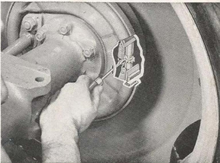
natural_image
Close-up of a mechanical assembly with a tool inserted into a component, no visible text or symbolsAdjusting Brake Shoes.
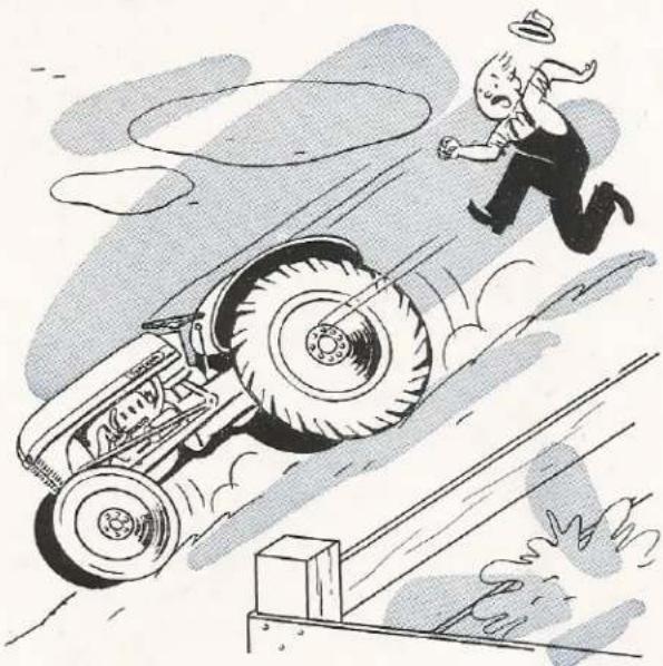
natural_image
Cartoon illustration of a person running away from a large vehicle on a track, with motion lines indicating speed (no text or symbols)Always set brakes before dismounting, when stopping on a hill or grade.
ing) until drag is felt on wheel. Back off adjusting screws (pull screw driver handle away from axle housing) until wheel rotates freely. Check drag after each "click".
- Check adjustment of the master brake to see that both brakes react evenly. This should be done by driving the tractor on level ground and applying the master brake. If brake linkage is correct, the tractor will come to a stop on a straight line. If it is not,

Brake Linkage.
the tractor will pull to the side with the shorter brake linkage. Shorten the longer brake linkage by adjusting the clevis on the rod. Both brake linkages should have a small amount of free play before brakes are applied. Therefore, care must be taken not to get them too tight.

The Ferguson Linkage utilizes the resistance and weight of the soil to increase Rear Wheel Traction.
D. FERGUSON SYSTEM
The Ferguson System employs a combination of linkages and hydraulic mechanism for the control of farm implements. The Ferguson System provides continuous automatic draft control of soil engaging implements and allows the operator to control the implement hydraulically from the tractor seat.
The Ferguson System utilizes three links instead of one to attach an implement to the tractor, thereby dividing the pulling force of the tractor into three components (three links), the bottom two links in tension or pulling, the upper link in compression or pushing. The system, thereby utilizes this basic principle in tractor-implement relationship which results in greater safety and efficiency.
Only the Ferguson System performs all of the following:
- Provides penetration without excess implement weight.
- Provides automatic draft control and finger-tip hydraulic control. The finger-tip control enables the operator to raise, lower or control an implement from the tractor seat by merely repositioning the finger-tip control lever.
- Provides traction without built-in tractor weight.
- Insures against tractor rotating about rear wheels. This is provided by the action of the compressive

The Ferguson System Hydraulic Mechanism. (A) Master Control Spring. (B) Finger-tip Control Lever. (C) Ram Cylinder Piston. (D) Hydraulic Pump Piston. (E) Oscillating Control Valve. (F) Power Take-Off.
forward, oil is released from the cylinder permitting the implement to be lowered by its own weight. When the implement reaches the desired depth (controlled by position of finger-tip control lever) the oil release from the ram cylinder is automatically stopped. The implement will, therefore, remain at this depth if the draft or soil texture remains unchanged. On uneven ground, expansion and compression of the master control spring regulates and controls the cylinder oil flow. If the soil texture becomes heavier, the top link will be subjected to a greater reaction, thereby compressing the main control spring. This in turn, allows oil to flow into the cylinder raising the implement until the corresponding draft is obtained. It is evident, therefore, if large variations in soil texture are encountered, repositioning of the finger-tip control lever will
be necessary to maintain desired depth.
force occurring in the upper link.
- Automatically protects tractor, implement and operator by completely releasing the implement weight from the rear wheels the instant the implement strikes an underground obstruction.
The Ferguson linkage is raised by a hydraulic pump driven by the power take-off. The pump is capable of delivering oil under 2,000 pounds pressure to the ram cylinder where the pressure is converted to a force which raises the linkage, in turn raising the attached implement.
NOTE: The hydraulic pump remains in operation until the power take-off lever is disengaged.
The finger-tip control lever regulates the raising of the attached implement by controlling the flow of oil to the ram cylinder. To raise the implement pull finger-tip control lever to top position. During field operation, the master control spring assembly regulates this oil flow, to or from the ram cylinder providing automatic draft control. When the linkage with an implement attached is in the raised or transport position, the ram cylinder is full of oil under pressure. When the finger-tip control lever is moved
NOTE: During extremely cold weather, sluggish operation may be experienced until the oil is warmed up.

natural_image
Cartoon illustration of a person riding a tractor pulling a chain on a snowy path, with a barn and tree in the background (no text or symbols)Never pull from upper link connection.
Should the implement strike a hidden object, the impact will release the oil pressure from the ram cylinder, thereby automatically removing the implement weight from the tractor. This in turn, reduces the rear wheel traction which causes the wheels to spin and results in less pull on the implement, thus providing an automatic built-in safety feature which operates instantly upon striking an underground obstruction and thus protects the implement, tractor and operator.
1. SERVICING THE FERGUSON SYSTEM
MASTER CONTROL SPRING
The master control spring is properly adjusted at the factory, however, every Spring and Fall it should be removed and grease applied to the threaded portion of the plunger to prevent rusting and freezing of the yoke threads.
To adjust spring, attach the implement to the tractor and raise to transport position. (Finger-tip control lever in topmost position.) Adjust end play of spring by threading in yoke until spring can be rotated freely by hand with a minimum of end play yet with no preload existing.
QUADRANT
The quadrant must have the correct relationship with the finger-tip control lever in order to obtain proper functioning of the Ferguson System. To

Lift Arms should be just beginning to lower.
determine if the quadrant needs adjusting, move finger-tip control 2½ inches from topmost position and implement should just begin to lower. If lowering starts before or after this point, the quadrant will have to be adjusted.
To adjust quadrant:
- Adjust master control spring per above paragraph.
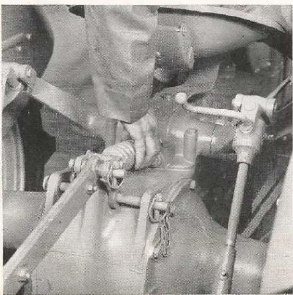
natural_image
Close-up of mechanical components including hoses and springs, no visible text or symbolsAdjusting Master Control Spring.
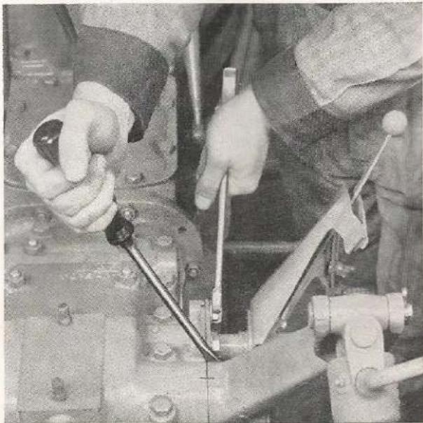
natural_image
Close-up of hands operating a mechanical device with tools (no visible text or symbols)Adjusting Quadrant.
- Attach tillage tool to tractor, start engine and raise implement to transport position.
- Mark lowering position on quadrant 2½ inches from topmost position.
- Loosen four cap screws located on quadrant housing. These cap screws pass through four slotted holes which permits adjustment of the plate.
- Move quadrant assembly to rearmost position and set finger-tip control lever to lowering mark.
- Tighten cap screws enough so quadrant still can move, but so it cannot shift position.
- Slowly move quadrant assembly forward with screwdriver until implement just starts to lower.
- Tighten cap screws and recheck setting.
FINGER-TIP CONTROL FRICTION DISC
The finger-tip control lever is held in position by a friction disc which after considerable usage may become worn. This condition can be determined if lever slips from position.

natural_image
Close-up of a mechanical assembly with a hand operating a tool, no visible text or symbolsAdjusting pressure on Friction Disc.
To adjust control lever:
- Remove cotter pin from castellated nut at lower end of lever and tighten nut until lever is firmly seated.
- Replace cotter pin.
NOTE: If above adjustment fails to remedy finger-tip control lever slippage, a new friction disc must be installed.
2. CHANGING HYDRAULIC SYSTEM, TRANSMISSION AND DIFFERENTIAL OIL
The mineral oil used in the hydraulic system also lubricates the transmission and differential gears and bearings. Therefore, three drain plugs have to be removed when changing oil.
As delivered to you, the system is filled with break-in oil which should be drained after the first 50 hours of operation. Thereafter, the oil should be changed every 750 hours.
CAUTION: It is essential that only a straight S.A.E. mineral gear oil be used in your hydraulic system. Purchase this lubricant from your Ferguson Dealer, as inferior or wrong type of oils can cause more serious damage and harm than many thousands of hours of use under normal operation. See Lubrication Section Pages 2 and 3.
E. FRONT AXLE AND STEERING
The front axle and steering assembly of your Ferguson Tractor includes an adjustable three-section front axle, radius rods, steering drag links, spindles, wheels, steering wheel, steering column and steering gear housing.
1. THREE-SECTION FRONT AXLE
The center section of the front axle pivots and is supported by 1 34 inch cadmium plated pivot pin. The pivot pin allows the axle to rock in relation to the tractor as the wheels follow the contour of the ground. This Ferguson Feature also permits a forward and rearward movement of the axle on the pin when the wheel tread spacings are changed, thereby making it possible to change the spacing without the altering of the steering geometry or wheel alignment.
NOTE: The pivot pin should not be greased, as dirt and dust will collect, causing excessive wear. If a squeaking is evident during operation, coat pin with dry graphite.
The outer axle sections are bolted to the center section by two bolts which, if spaced in any of a series of holes, adjust the tread width (see Page 14 for tread adjustment). Each outer axle is braced by a radius rod attached to the transmission housing. The wheel spindles housed in the outer axle sections, turn in steel-backed bronze bushings at the top and bottom of the housing. Weight is transferred from axle to spindle through a thrust bearing at the lower end of the axle. The front wheel consists of a hub and wheel disc incorporating a six-inch bolt circle. The wheel is bolted to the hub, which is mounted on the spindle with two tapered roller bearings, which should be packed annually.
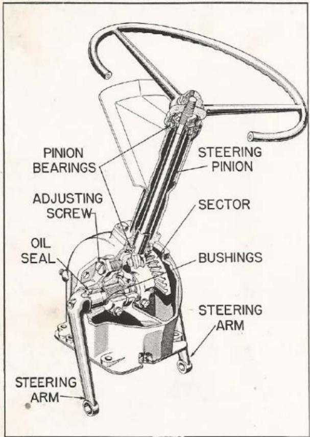
Steering Gear.
2. STEERING GEAR
The steering gear is specially designed for use with the three-section front axle. The steering wheel pinion operates the two sectors simultaneously; one moves forward, the other backward. The sectors, in turn, control the steering arms, drag links and front wheels. Both the radius rods and drag links are the same length, operate one directly above the other and move in the same manner; therefore, when the wheel spacing is changed, the wheel alignment and steering geometry remains unchanged.
Clearance between the pinion and sectors is controlled by two adjusting screws, one on each side of the housing which holds the sector in correct mesh with the pinion gear. These adjusting screws should be turned in against the sectors until they are meshed full depth against the pinion gear. Check for binding over the full length of travel by turning the wheels from one extreme to the other. If binding is evident, loosen set screw and retighten locknut. Recheck for binding.
3. SERVICING STEERING ASSEMBLY HOUSING OIL LEVEL
The level of the oil in the steering housing should be maintained at the center of the steering arms. If oil is low, add transmission oil. Normally, the oil will not require changing; however, if necessary, the steering housing will have to be removed from the tractor and drained.
NOTE: The steering wheel pinion shaft bearings are lubricated at the time of manufacture and will need no further lubrication.
SPINDLES, STEERING JOINTS AND FRONT WHEELS
Grease spindles and steering joints daily during operation with a pressure gun lubricant.
Annually, the front wheels should be removed and the bearings cleaned and repacked with a short fiber grease.
When reassembling front wheels, adjust bearings by tightening castellated nut until a slight drag is noted when the wheel is turned, then back off nut so cotter pin can be installed.
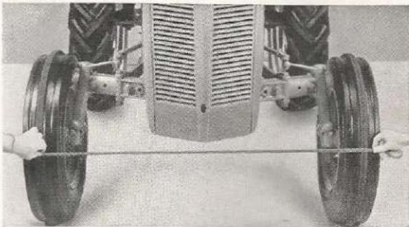
natural_image
Close-up of a tractor's front wheel and rear tires with hands adjusting the rim (no visible text or symbols)Measuring toe-in.
WHEEL ALIGNMENT
Periodically check the wheel alignment for toe-in of 0- 14 ". This is accomplished by measuring between the tire rib centers at hub height at both front and rear of wheels, and noting the difference. To adjust, loosen bolts at back and at front of each drag link and turn in or out as required. Retighten clamp bolts. Be sure to keep both drag links approximately the same length.
NOTE: If radius rod ball ends become loose at
steering housing, remove shims as required. After shims are removed and radius rod ball clamps replaced, jack front end of tractor off the ground and rock axle to see if any binding occurs.

Adjusting Drag Links.
SPECIFICATIONS
CAPACITIES
Gasoline Tank....10 U.S. gallons
(8.3 Imperial gallons)
Cooling System....10 U.S. quarts
(8.3 Imperial quarts)
Crankcase....5 U.S. quarts
(4.2 Imperial quarts)
Transmission, Differential and Ferguson
Hydraulic System....6 U.S. gallons
(5 Imperial gallons)
If auxiliary hydraulic equipment is used requiring more than 1 U.S. gallon, the amount in excess must be added for satisfactory operation. When detaching equipment, drain to "full mark" on dipstick.
Steering Gear Housing....2 U.S. quarts
Air Filter Oil Bath....Fill to mark on bowl
DIMENSIONS
Wheel Base 70 inches
Overall Length 115 inches
Normal Tread—Front....48 inches
Normal Tread—Rear 52 inches
Overall Width....63 inches
(with 52" Rear Tread—11" Tires)
Overall Width....87 inches
(with 76" Rear Tread—11" Tires)
Ground Clearance—Under Center....13 inches
Ground Clearance—Under Axle.....21 inches
Turning Circle diameter with use of brakes.16 feet
Weight....2,570 pounds
(Operating—tank full, lights, etc.)
ENGINE
Cylinder Bore....31/4 inches
Stroke....37/8 inches
Piston Displacement....129 cubic inches
Compression Ratio....6.5 to 1
Idle Speed....400 r.p.m.
Top Speed (No Load)....2,200 r.p.m.
Valves—Overhead high lift Rotocap on exhaust.
Tappet clearance at .013 cold—both intake and exhaust.
Governor—Variable speed, centrifugal fly-ball type.
Lubrication—Pressure by gear pump to crankshaft, camshaft, connecting rods and rocker arms. Gauge reading 15 to 30 lbs. Float type intake.
Oil Filter—Replaceable cartridge type. Filters from outside inward.
Cooling System—Circulation by centrifugal type pump with recirculating system. Flow controlled thermostatically through tube and fin type radiator.
Fuel—Gravity flow. Designed to maintain one gallon reserve. Up-draft, dust-proof carburetor. Oil bath type air cleaner.
ELECTRICAL SYSTEM
Battery—6 volt, 80 ampere hour capacity, 13 plates.
Starting—Automotive type safety starter switch, operated by gear shift lever.
Charging—6 volt, 3 brush generator. Output 16 to 19 amps at operating temperature. Combination voltage current control and cutout relay type regulator.
Ignition—Automotive type with gear driven distributor having automatic spark advance mechanism.
POWER TRAIN
Single plate dry disc type clutch. Constant mesh helical gear transmission. 4 speeds forward, 1 reverse. Spiral bevel gear final drive with straddle mounted pinion. 6.66 to 1 ratio.
HYDRAULIC SYSTEM
Ferguson internal type with piston pump developing 2,000 lbs. per square inch pressure.
POWER TAKE-OFF
118'' diameter spline with quick attaching snap ring groove.
BRAKES
Internal expanding, two shoe, self-energizing type. Operated together or independently to facilitate short turning.
See Your Dealer For Information on...
the
FERGUSON SYSTEM
and
THESE FERGUSON IMPLEMENTS
Moldboard Plows
Disc Plows
Two-Way Plows
Spike Tooth Harrows
Spring Tooth Harrows
Lift Type Disc Harrows
Tandem Disc Harrows
Heavy Duty Harrows
Spring-Tine Cultivators
Rigid-Tine Cultivators
Lister Cultivators
Agricultural Mowers
Heavy-Duty Mowers
Multi-Purpose Blades
Sub Sailers
Manure Spreaders
Manure Loaders
Corn Pickers
Corn Planters
Lister Planters
Grain Drills
Side Delivery Rakes
Rotary Hoes
Cordwood Saws
Rear Cranes
Tillers
Middlebusters
Four-Row Weeders
Four-Wheel Wagons
Soil Scoops
FORM NO.Z-3481-C
15M-11-53
FARM WITH THE FAMOUS ERGUSON SYSTEM ELEMENTS
PRINTED IN U.S.A.
Ferguson


- Ferguson park...
- HARRY FERGUSON, INC.
- TRACTOR
- WARRANTY
- foreword
- the Ferguson tractor...
- with Ferguson hydraulic system
- periodic maintenance
- LUBRICATION
- PRESSURE TYPE GREASE FITTINGS
- CRANKCASE DIPSTICK
- TRANSMISSION DIPSTICK
- AIR CLEANER BOWL
- ENGINE CRANKCASE
- DISTRIBUTOR
- GENERATOR
- OIL FILTER ELEMENT
- TRANSMISSION, HYDRAULIC SYSTEM AND DIFFERENTIAL
- STEERING HOUSING OIL LEVEL
- DISTRIBUTOR RESERVOIR
- WHEEL BEARINGS
- MAINTENANCE
- DAILY MAINTENANCE (10 hours)
- WEEKLY MAINTENANCE (50 hours)
- SEMI-MONTHLY MAINTENANCE (100 hours)
- MONTHLY MAINTENANCE (200 hours)
- SPRING AND FALL MAINTENANCE (750 hours)
- YEARLY MAINTENANCE (1,000 hours)
- operating instructions
- INSTRUMENTS AND CONTROLS
- IGNITION SWITCH
- OIL PRESSURE GAUGE
- AMMETER
- CHOKE
- THROTTLE
- GEAR SHIFT LEVER
- STARTER SWITCH
- HOOD LATCH
- FINGER-TIP CONTROL LEVER
- CLUTCH PEDAL
- LEFT WHEEL BRAKE PEDAL
- RIGHT WHEEL BRAKE PEDAL
- MASTER BRAKE PEDAL
- MASTER BRAKE PEDAL LOCK
- FUEL SHUT-OFF VALVE
- DOUBLE HINGE SEAT
- BREAKING-IN PERIOD
- STARTING THE ENGINE
- OBSERVING THE INSTRUMENTS
- STARTING THE TRACTOR IN MOTION
- DRIVING THE TRACTOR
- WARNING
- CHOOSING THE CORRECT GEAR
- A TEST FOR OVERLOADING
- STOPPING THE TRACTOR
- USING THE FERGUSON SYSTEM
- ATTACHING AN IMPLEMENT
- RAISING AND TRANSPORTING IMPLEMENTS
- OPERATING WITH SOIL ENGAGING IMPLEMENTS
- DETACHING IMPLEMENTS
- USING EXTERNAL HYDRAULIC CYLINDER
- DRAWBAR INSTALLATION AND POWER TAKE-OFF OPERATION
- STANDARD DRAWBAR
- POWER TAKE-OFF
- POWER TAKE-OFF ADAPTERS (Accessories)
- BELT PULLEY (Accessory)
- ADJUSTING WHEEL TREAD WIDTHS
- FRONT WHEEL WIDTHS
- REAR WHEEL WIDTHS
- CARE AND INFLATION OF YOUR TRACTOR TIRES
- RESULTS OF UNDER-INFLATION
- RESULTS OF OVER-INFLATION
- FOR LONGER TIRE LIFE
- ADDED WEIGHT FOR TRACTION
- LIQUID FILL
- FRONT WHEEL WEIGHTS (Accessory)
- STORING YOUR FERGUSON TRACTOR
- STARTING ENGINES THAT HAVE BEEN IN STORAGE
- servicing your tractor
- YOUR FERGUSON ENGINE
- OILING SYSTEM
- OIL PUMP
- OIL FILTER
- CHANGING CRANKCASE OIL AND FILTER ELEMENT
- COOLING SYSTEM
- RADIATOR
- RADIATOR CAP
- FAN AND WATER PUMP
- THERMOSTAT AND HOSES
- CARE OF COOLING SYSTEM
- AIR AND FUEL SYSTEM
- AIR CLEANER
- Care of the Air Cleaner
- FUEL FILTER AND SEDIMENT BOWL
- Care of Fuel Filter and Sediment Bowl
- CARBURETOR
- Carburetor Adjustments
- IDLING AIR
- IDLING SPEED
- MAIN JET
- Draining Carburetor
- Store Your Fuel Properly
- BATTERY
- Cracked or broken case.
- Distributor Inspection and Servicing
- Engine Timing
- To Time Engine
- IGNITION COIL
- Generator Servicing
- STARTING MOTOR
- GENERATOR REGULATOR
- SPARK PLUGS
- VALVE ADJUSTMENT
- GOVERNOR
- GOVERNOR ADJUSTMENT
- TRANSMISSION AND CLUTCH
- TRANSMISSION
- CLUTCH
- DIFFERENTIAL AND REAR AXLE ASSEMBLY
- DIFFERENTIAL
- REAR AXLE ASSEMBLY
- PACKING THE REAR WHEEL BEARING
- BRAKES
- Brake Adjustment
- FERGUSON SYSTEM
- SERVICING THE FERGUSON SYSTEM
- MASTER CONTROL SPRING
- QUADRANT
- To adjust quadrant:
- FINGER-TIP CONTROL FRICTION DISC
- To adjust control lever:
- CHANGING HYDRAULIC SYSTEM, TRANSMISSION AND DIFFERENTIAL OIL
- FRONT AXLE AND STEERING
- THREE-SECTION FRONT AXLE
- STEERING GEAR
- SERVICING STEERING ASSEMBLY HOUSING OIL LEVEL
- SPINDLES, STEERING JOINTS AND FRONT WHEELS
- WHEEL ALIGNMENT
- SPECIFICATIONS
- CAPACITIES
- DIMENSIONS
- ENGINE
- ELECTRICAL SYSTEM
- POWER TRAIN
- HYDRAULIC SYSTEM
- See Your Dealer For Information on...
- FERGUSON SYSTEM
- THESE FERGUSON IMPLEMENTS
Brand : Ferguson
Model : TO-30
Category : Tractor