
AN922 - Pneumatic nailer MAKITA - Free user manual and instructions
Find the device manual for free AN922 MAKITA in PDF.


| Product Type | Cordless Finish Nailer |
| Model | AN922 |
| Brand | Makita |
| Dimensions (L x W x H) | 10.5 x 12.4 x 3.1 inches |
| Weight (with battery) | 4.6 lbs |
| Power Source | 18V LXT Lithium-Ion Battery |
| Fastener Type | 18-gauge finish nails (5/8" to 2") |
| Magazine Capacity | 110 nails |
| Driving Speed | Up to 90 nails per minute |
| Depth Adjustment | Tool-free adjustable depth control |
| Dry Fire Lockout | Prevents firing when magazine is empty |
| No-Mar Tip | Protects workpiece surface |
| Trigger Modes | Sequential and contact (bump) operation |
| Safety Features | Trigger lock-off, safety nose |
| Maintenance | Periodic cleaning and lubrication; wipe with dry cloth |
| Spare Parts Availability | Through authorized Makita service centers |
| Repairability | Repairable with genuine Makita parts |
| Warranty | 3-year factory warranty (See manual for details) |
Frequently Asked Questions - AN922 MAKITA
User questions about AN922 MAKITA
0 question about this device. Answer the ones you know or ask your own.
Ask a new question about this device
Download the instructions for your Pneumatic nailer in PDF format for free! Find your manual AN922 - MAKITA and take your electronic device back in hand. On this page are published all the documents necessary for the use of your device. AN922 by MAKITA.
USER MANUAL AN922 MAKITA
Pneumatic Framing Nailer
MODEL AN922
MODEL AN942
INSTRUCTION MANUAL

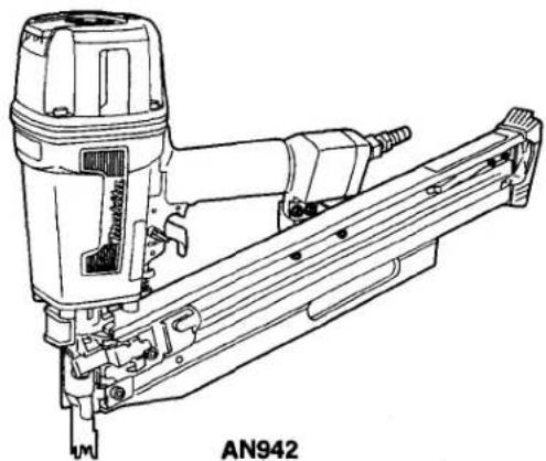
SPECIFICATIONS
| Model | Air pressure | Nail length | Nail capacity | Dimensions(L x H x W) | Min. hose diameter | Net weight |
| AN922 | 4.5 — 8.5 kgf/cm2G(65 — 120 PSIG) | 50 mm — 90 mm(2" — 3-1/2") | 64 — 74 pcs. | 540 mm x 376 mm x 108 mm(21-1/4" x 14-3/4" x 4-1/4") | 8.5 mm (5/16") | 3.8 kg (8.4 lbs) |
| AN942 | 60 — 84 pcs. | 446 mm x 376 mm x 108 mm(17-1/2" x 14-3/4" x 4-1/4") |
* Manufacturer reserves the right to change specifications without notice.
* Note: Specifications may differ from country to country.
WARNING: For your personal safety, READ and UNDERSTAND before using.
SAVE THESE INSTRUCTIONS FOR FUTURE REFERENCE
IMPORTANT SAFETY INSTRUCTIONS
WARNING: WHEN USING THIS TOOL, BASIC SAFETY PRECAUTIONS SHOULD ALWAYS BE FOLLOWED TO REDUCE THE RISK OF PERSONAL INJURY, INCLUDING THE FOLLOWING:
READ ALL INSTRUCTIONS.
- For personal safety and proper operation and maintenance of the tool, read this instruction manual carefully before using the tool.

• Always wear safety glasses to protect your eyes from dust or nail injury. The safety glasses should conform with the requirements of ANSI Z87. 1 — 1979.
WARNING:
It is an employer's responsibility to enforce the use of safety eye protection equipment by the tool operators and by other persons in the immediate working area.
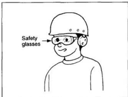
- Wear hearing protection to protect your ears against exhaust noise and head protection. Also wear light but not loose clothing. Sleeves should be buttoned or rolled up. No necktie should be worn.

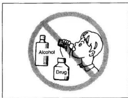
- Rushing the job or forcing the tool is dangerous. Handle the tool carefully. Do not operate when under the influence of alcohol, drugs or the like.
- General Tool Handling Guidelines:
- Always assume that the tool contains fasteners.
- Do not point the tool toward yourself or anyone whether it contains fasteners or not.
- Do not activate the tool unless the tool is placed firmly against the workpiece.
-
Respect the tool as a working implement.
-
No horseplay.
-
Do not hold or carry the tool with a finger on the trigger.
-
Do not load the tool with fasteners when any one of the operating controls is activated.
-
Do not operate the tool with any power source other than that specified in the tool operating/safety instructions.
- An improperly functioning tool must not be used.

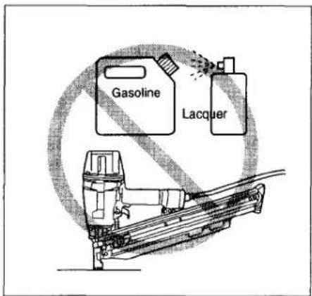
• Sparks sometimes fly when the tool is used. Do not use the tool near volatile, flammable materials such as gasoline, thinner, paint, gas, adhesives, etc.; they will ignite and explode, causing serious injury.
• The area should be sufficiently illuminated to assure safe operations.
The area should be clear and litter-free. Be especially careful to maintain good footing and balance.

- Only those involved in the work should be in the vicinity. Children especially must be kept away at all times.

- There may be local regulations concerning noise which must be complied with by keeping noise levels within prescribed limits. In certain cases, shutters should be used to contain noise.

- Do not play with the contact element: it prevents accidental discharge, so it must be kept on and not removed. Securing the trigger in the ON position is also very dangerous. Never attempt to fasten the trigger.
Do not operate a tool if any portion of the tool operating controls is inoperable, disconnected, altered, or not working properly.

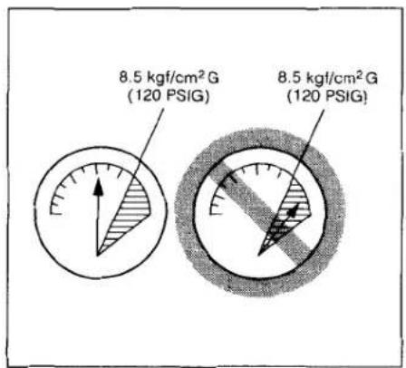
- Operate the tool within the specified air pressure of 4.5 — 8.5 kgf/cm²G (65 — 120 PSIG) for safety and longer tool life. Do not exceed the recommended max. operating pressure of 8.5 kgf/cm²G (120 PSIG). The tool should not be connected to a source whose pressure potentially exceeds 14.0 kgf/cm²G (200 PSIG).
- Never use the tool with other than compressed air. If bottled gas (carbon dioxide, oxygen, nitrogen, hydrogen, air, etc.) or combustible gas (hydrogen, propane, acetylene, etc.) is used as a power source for this tool, the tool will explode and cause serious injury.

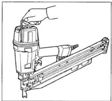
• Always check the tool for its overall condition and loose screws before operation. Tighten as required.
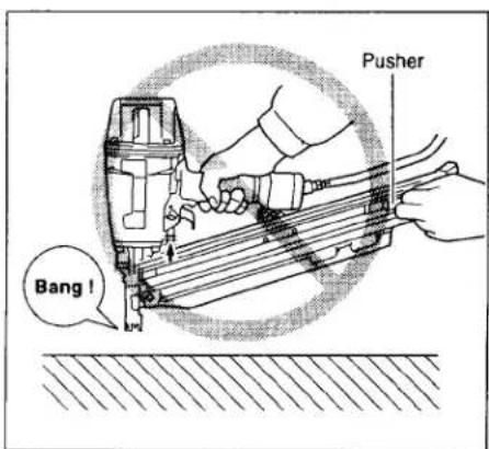
- Make sure all safety systems are in working order before operation. The tool must not operate if only the trigger is pulled or if only the contact arm is pressed against the wood. It must work only when both actions are performed. Test for possible faulty operation with nails unloaded and the pusher in fully pulled position.

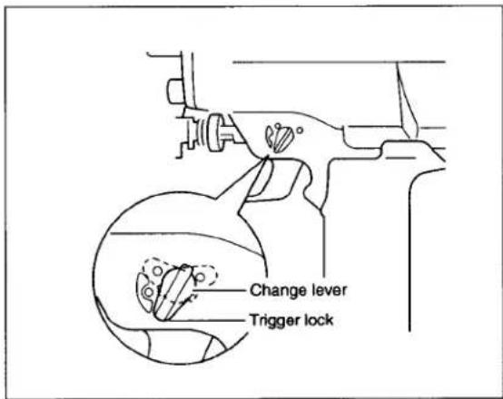
- Make sure that the trigger is locked when the change lever is set to the LOCK position.

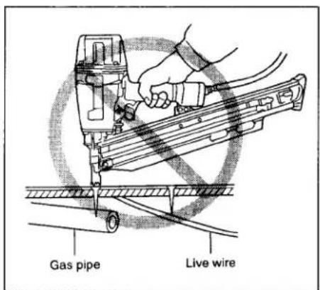
- Check walls, ceilings, floors, roofing and the like carefully to avoid possible electrical shock, gas leakage, explosions, etc. caused by striking live wires, conduits or gas pipes.
- Use only nails specified in this manual. The use of any other nails may cause malfunction of the tool.
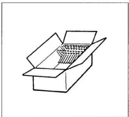
- Do not permit those uninstructed to use the tool.
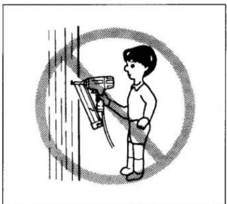
- Make sure no one is nearby before nailing. Never attempt to nail from both the inside and outside at the same time. Nails may rip through and/or fly off, presenting a grave danger.

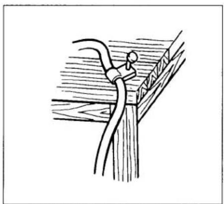
- Watch your footing and maintain your balance with the tool. Make sure there is no one below when working in high locations, and secure the air hose to prevent danger if there is sudden jerking or catching.
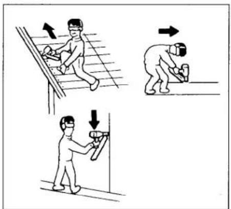
- On rooftops and other high locations, nail as you move forward. It is easy to lose your footing if you nail while inching backward. When nailing against perpendicular surface, nail from the top to the bottom. You can perform nailing operations with less fatigue by doing so.
- A nail will be bent or the tool can become jammed if you mistakenly nail on top of another nail or strike a knot in the wood. The nail may be thrown and hit someone, or the tool itself can react dangerously. Place the nails with care.

- Do not leave the loaded tool or the air compressor under pressure for a long time out in the sun. Be sure that dust, sand, chips and foreign matter will not enter the tool in the place where you leave it setting.

- Do not point the ejection port at anyone in the vicinity. Keep hands and feet away from the ejection port area.
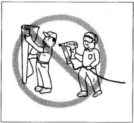
- When the air hose is connected, do not carry the tool with your finger on the trigger or hand it to someone in this condition. Accidental firing can be extremely dangerous.
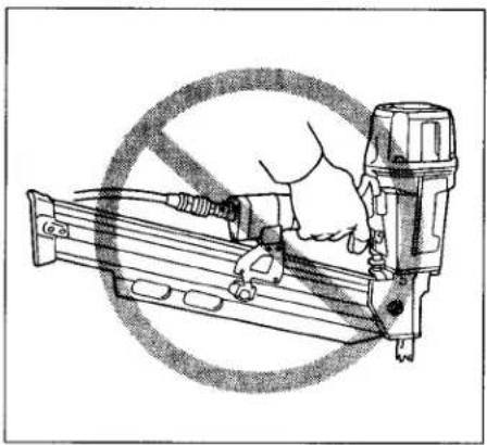
- Handle the tool carefully as there is high pressure inside the tool that can be dangerous if a crack is caused by rough handling (dropping or striking). Do not attempt to carve or engrave on the tool.

- Stop nailing operations immediately if you notice something wrong or out of the ordinary with the tool.
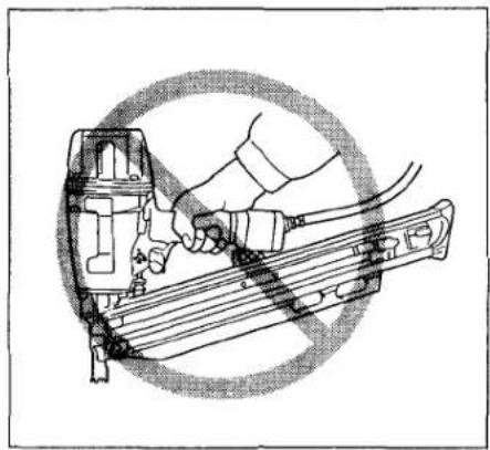
• Always disconnect the air hose and remove all of the nails:
- When unattended.
- Before performing any maintenance or repair.
- Before cleaning a jam.
- Before moving the tool to a new location.
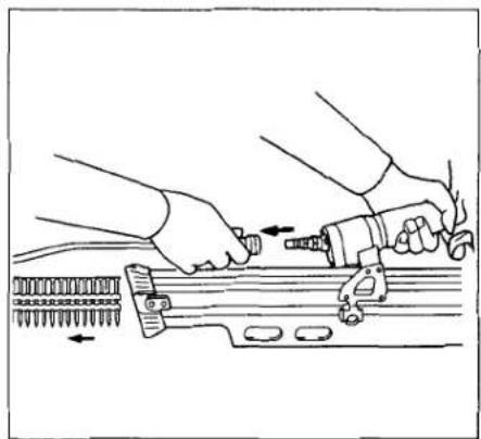
- Perform cleaning and maintenance right after finishing the job. Keep the tool in tip-top condition. Lubricate moving parts to prevent rusting and minimize friction related wear. Wipe off all dust from the parts.

- When not operating the tool, always lock the trigger by turning the change lever to the LOCK position.

- Do not operate this tool if it does not contain a legible WARNING LABEL.

- Do not modify tool without authorization from Makita.
- Ask Makita's Factory or Authorized service center for periodical inspection of the tool.
• To maintain product SAFETY and RELIABILITY, maintenance and repairs should be performed by Makita Authorized or Factory Service Centers, always using Makita replacement parts.

SAVE THESE INSTRUCTIONS.
TOOL INSTALLATION INSTRUCTIONS AND USE Selecting compressor
The air compressor must comply with the requirements of ANSI B19.3 - 1981.
Select a compressor that has ample pressure and air output to assure cost-efficient operation. The graph shows the relation between nailing frequency, applicable pressure and compressor air output. Thus, for example, if nailing takes place at a rate of approximately 40 times per minute at a compression of 6 kgf/cm²G (85 PSIG), a compressor with an air output over 3 ft³/minute is required. Pressure regulators must be used to limit air pressure to the rated pressure of the tool where air supply pressure exceeds the tool's rated pressure. Failure to do so may result in serious injury to tool operator or persons in the vicinity.

Selecting air hose
Use an air hose as large and as short as possible to assure continuous, efficient nailing operation. With an air pressure of 5 kgf/cm²G (70 PSIG), an air hose with an internal diameter of over 8.5 mm (5/16") and a length of less than 20 m (6.6 ft.) is recommended when the interval between each nailing is 0.5 seconds. Air supply hoses shall have a minimum working pressure rating of 10.7 kgf/cm²G (150 PSIG) or 150 percent of the maximum pressure produced in the system whichever is higher.

CAUTION:
Low air output of the compressor, or a long or smaller diameter air hose in relation to the nailing frequency may cause a decrease in the driving capability of the tool.
Lubrication
To insure maximum performance, install an air set (oiler, regulator, air filter) as close as possible to the tool. Adjust the oiler so that one drop of oil will be provided for every 30 nails.

When an air set is not used, oil the tool with pneumatic tool oil by placing 2 (two) or 3 (three) drops into the air fitting. This should be done before and after use. For proper lubrication, the tool must be fired a couple of times after pneumatic tool oil is introduced.

Nose adapter
CAUTION:
Always lock the trigger and disconnect the hose before installing or removing the nose adapter.
When nailing workpieces with easily-marred surfaces, use the nose adapter. It is stored in the holder on the reverse side of the magazine.

Attach the nose adapter to the contact arm (see right). When not in use, store the nose adapter in the holder on the reverse side of the magazine to keep it from being lost.

Loading nailer
CAUTION:
Always lock the trigger and disconnect the hose before loading the nailer.
Select nails suitable for your work. Insert strip of nails into the magazine

Pull the pusher lever to the rear to engage the pusher to the last nail.

Unloading nailer
CAUTION:
Always disconnect the air hose before unloading the nailer.
Pull the pusher lever to the rear. Return the pusher lever back while keeping the pusher depressed to disengage it from the strip of nails.

Depress the nail stopper and remove the strip of nails from the magazine.

Adjusting depth of nailing
CAUTION:
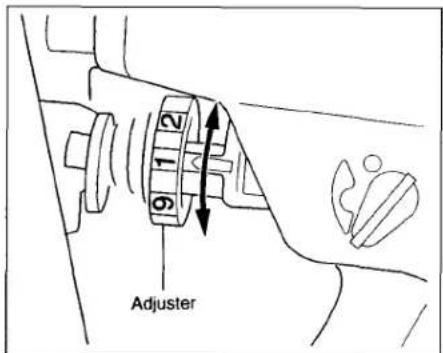
Always lock the trigger and disconnect the hose before adjusting the depth of nailing.
To adjust the depth of nailing, turn the adjuster so that the arrow above the adjuster will point to the number indicated on the adjuster. The depth of nailing is the deepest when the arrow points to the number 1. It will become shallower as the arrow points to higher number. The depth can be changed in approx. 1.0 mm (1/32") increments per graduation. If nails cannot be driven deep enough even when the arrow points to the number 1, increase the air pressure. If nails are driven too deep even when the arrow points to the number 9, decrease the air pressure. Generally speaking, the tool service life will be longer when the tool is used with lower air pressure and the adjuster set to a lower number.
Connecting air hose
Lock the trigger. Slip the air socket of the air hose onto the air fitting on the nailer. Be sure that the air socket locks firmly into position when installed onto the air fitting. A hose coupling must be installed on or near the tool in such a way that the pressure reservoir will discharge at the time the air supply coupling is disconnected.

Operation
CAUTION:
Make sure all safety systems are in working order before operation.
1) To drive a nail, you may place the contact element against the workpiece and pull the trigger, or 2) Pull the trigger first and then place the contact element against the workpiece.
No. 1 method is for intermittent nailing, when you wish to drive a nail carefully and very accurately.
No. 2 method is for continuous nailing.


For No. 1 method, set the change lever to the "Intermittent Nailing" position.
For No. 2 method, set the change lever to the "Continuous Nailing" position. After using the change lever to change the nailing method, always make sure that the change lever is properly set to the position for the desired nailing method.

Anti dry fire mechanism
This tool is equipped with an anti dry fire mechanism. When there are a few nails remaining in the magazine, the contact arm will be locked in the undepressed position to prevent the tool from being activated. Load more nails to resume operation.
Jammed nailer
CAUTION:
Always lock the trigger, disconnect the hose and remove the nails from the magazine before cleaning a jam.
When the nailer becomes jammed, do as follows:
Insert a small rod or the like into the ejection port and tap it with a hammer to retract the driver. Use pliers to bend the jammed nail so that the nail head comes out of the slot in the driver guide. Then remove the jammed nail.


Nails
Handle nail strips and their box carefully. If the nail strips have been handled roughly, they may be out of shape or their connector breaks, causing poor nail feed.

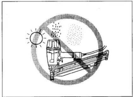
Avoid storing nails in a very humid or hot place or place exposed to direct sunlight.

MAINTENANCE
CAUTION:
Always disconnect the hose before attempting to perform inspection or maintenance.
Maintenance of nailer
Always check the tool for its overall condition and loose screws before operation. Tighten as required.
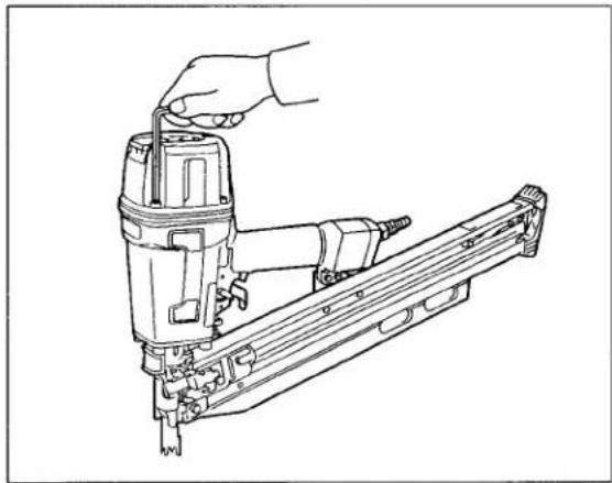
With tool disconnected, make daily inspection to assure free movement of the contact element and trigger. Do not use tool if the contact element or trigger sticks or binds.

Make sure that the trigger is locked when the change lever is set to the LOCK position.
When the tool is not to be used for an extended period of time, lubricate the tool using pneumatic tool oil and store the tool in a safe place. Avoid exposure to direct sunlight and/or a humid or hot environment.

Maintenance of compressor, air set and air hose
After operation, always drain the compressor tank and the air filter. If moisture is allowed to enter the tool, it may result in poor performance and possible tool failure.


Check regularly to see if there is sufficient pneumatic oil in the oiler of the air set. Failure to maintain sufficient lubrication will cause O-rings to wear quickly.

Keep the air hose away from heat (over 60°C, over 140°F), away from chemicals (thinner, strong acids or alkalis). Also, route the hose away from obstacles which it may become dangerously caught on during operation. Hoses must also be directed away from sharp edges and areas which may lead to damage or abrasion to the hose.

To maintain product SAFETY and RELIABILITY, maintenance and repairs should be performed by Makita Authorized or Factory Service Centers, always using Makita replacement parts.
(MEMO)
MAKITA LIMITED ONE YEAR WARRANTY
Warranty Policy
Every Makita tool is thoroughly inspected and tested before leaving the factory. It is warranted to be free of defects from workmanship and materials for the period of ONE YEAR from the date of original purchase. Should any trouble develop during this one-year period, return the COMPLETE tool, freight prepaid, to one of Makita's Factory or Authorized Service Centers. If inspection shows the trouble is caused by defective workmanship or material, Makita will repair (or at our option, replace) without charge.
This Warranty does not apply where:
• repairs have been made or attempted by others:
- repairs are required because of normal wear and tear:
- The tool has been abused, misused or improperly maintained;
- alterations have been made to the tool.
IN NO EVENT SHALL MAKITA BE LIABLE FOR ANY INDIRECT, INCIDENTAL OR CONSEQUENTIAL DAMAGES FROM THE SALE OR USE OF THE PRODUCT. THIS DISCLAIMER APPLIES BOTH DURING AND AFTER THE TERM OF THIS WARRANTY.
MAKITA DISCLAIMS LIABILITY FOR ANY IMPLIED WARRANTIES, INCLUDING IMPLIED WARRANTIES OF "MERCHANTABILITY" AND "FITNESS FOR A SPECIFIC PURPOSE," AFTER THE ONE-YEAR TERM OF THIS WARRANTY.
This Warranty gives you specific legal rights, and you may also have other rights which vary from state to state. Some states do not allow the exclusion or limitation of incidental or consequential damages, so the above limitation or exclusion may not apply to you. Some states do not allow limitation on how long an implied warranty lasts, so the above limitation may not apply to you.
- PNEUMATIC FRAMING NAILER
- IMPORTANT SAFETY INSTRUCTIONS
- READ ALL INSTRUCTIONS
- WARNING
- TOOL INSTALLATION INSTRUCTIONS AND USE SELECTING COMPRESSOR
- SELECTING AIR HOSE
- CAUTION
- LUBRICATION
- NOSE ADAPTER
- LOADING NAILER
- UNLOADING NAILER
- ADJUSTING DEPTH OF NAILING
- CONNECTING AIR HOSE
- OPERATION
- ANTI DRY FIRE MECHANISM
- JAMMED NAILER
- NAILS
- MAINTENANCE
- MAINTENANCE OF NAILER
- MAINTENANCE OF COMPRESSOR, AIR SET AND AIR HOSE
- MAKITA LIMITED ONE YEAR WARRANTY
Brand : MAKITA
Model : AN922
Category : Pneumatic nailer