
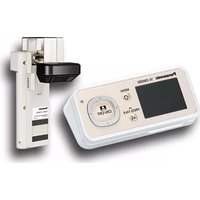
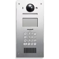
VL-GC003A - Intercom PANASONIC - Free user manual and instructions
Find the device manual for free VL-GC003A PANASONIC in PDF.


| Product Type | Wired Door Intercom |
| Model | VL-GC003A |
| Brand | Panasonic |
| Dimensions (approx.) | 150 x 100 x 30 mm |
| Weight (approx.) | 200 g |
| Power Supply | 12V DC (via adapter) |
| Communication | Two-way audio, hands-free |
| Door Release | Electric strike control |
| Night Vision | Not applicable (audio-only) |
| Weatherproof Rating | IP44 (suitable for outdoor use) |
| Operating Temperature | -10°C to +50°C |
| Installation | Surface mount, wired |
| Materials | ABS plastic, metal faceplate |
| Maintenance | Wipe with soft dry cloth; avoid solvents |
| Safety | Low voltage, CE certified |
| Compatibility | Panasonic VL series indoor monitors |
| Wiring | 2-wire connection (audio + control) |
| Spare Parts | Available from Panasonic authorized dealers |
| Repairability | Modular design; replaceable components |
| Manual | Downloadable from notice-facile.com |
Frequently Asked Questions - VL-GC003A PANASONIC
User questions about VL-GC003A PANASONIC
0 question about this device. Answer the ones you know or ask your own.
Ask a new question about this device
Download the instructions for your Intercom in PDF format for free! Find your manual VL-GC003A - PANASONIC and take your electronic device back in hand. On this page are published all the documents necessary for the use of your device. VL-GC003A by PANASONIC.
USER MANUAL VL-GC003A PANASONIC
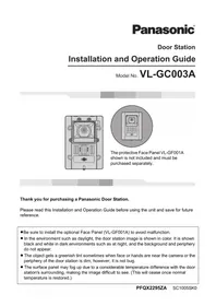
Installation and Operation Guide
Model No. VL-GC003A


The protective Face Panel VL-GF001A shown is not included and must be purchased separately.
Thank you for purchasing a Panasonic Door Station.
Please read this Installation and Operation Guide before using the unit and save for future reference.
- Be sure to install the optional Face Panel (VL-GF001A) to avoid malfunction.
- In the environment such as daylight, the door station image is shown in color. It is shown black and white in dark environments such as at night, and the background and periphery do not appear.
- The object gets a greenish tint sometimes when face or hands are near the camera or the periphery of the door station is dim, however, it is not bug.
- The surface panel may fog up due to a considerable temperature difference with the door station's surrounding, making the image difficult to see. (This will cease once normal temperature is restored.)
Important Information
Important safety instructions 3
Additional safety information 4
For best performance....4
Installation Introductions
Included items 5
Optional item information....5
Location of controls 6
Before installation. 7
Installing the door station....10
Help
Cleaning....13
General Information
Technical data about this product 14
FCC and Other Information 15


The lightning flash with arrow head within a triangle is intended to tell the user that parts inside the product are a risk of electric shock to persons.

The exclamation point within a triangle is intended to tell the user that important operating and servicing instructions are in the papers with the appliance.
Important safety instructions
1) Read these instructions. All the safety and operating instructions should be read before the appliance is operated. 2) Keep these instructions. The safety and operating instructions should be retained for future reference. 3) Heed all warnings. All warnings on the appliance and in the operating instructions should be adhered to. 4) Follow all instructions. All operating and use instructions should be followed. 5) Do not use this apparatus near water. For example, near a bathtub, wash bowl, kitchen sink, or laundry tub, in a wet basement, or near a swimming pool, and the like. 6) Clean only with dry cloth. Do not use liquid cleaners or aerosol cleaners. Use a dry cloth for cleaning. 7) Do not block any ventilation openings. Install in accordance with the manufacturer's instructions. Slots and Openings in the cabinet are provided for ventilation and to ensure reliable operation of the product and to protect it from overheating. The openings should never be blocked by placing the product on a bed, sofa, rug, or other similar surface. 8) Do not install near any heat sources such as radiators, heat registers, stoves, or other apparatus (including amplifiers) that produce heat. This product should not be placed in a built-in installation such as a bookcase or rack unless proper ventilation is provided or the manufacturer's instructions have been adhered to. 9) Only use attachments / accessories specified by the manufacturer. 10) Refer all servicing to qualified service personnel. Servicing is required when the apparatus has been damaged in any way, such as power-supply cord or plug is damaged, liquid has been spilled or objects have fallen into the apparatus, the apparatus has been exposed to rain or moisture, does not operate normally, or has been dropped.
SAVE THESE INSTRUCTIONS
Additional safety information
- Use only the power source marked on the unit. If you are not sure of the type of power supplied to your home, consult your dealer or local power company.
- Use only the specified AC adaptor.
- Do not tamper with the plug.
- Make sure the plug is securely inserted.
- Do not touch the plug with wet hands.
- Do not place objects on the power cord. Install the unit where no one can step or trip on the cord.
- To reduce the risk of electric shock, do not disassemble this unit. Take the unit to an authorized service center when service is required. Opening or removing covers may expose you to dangerous voltages or other risks. Incorrect reassembly can cause electric shock when the unit is subsequently used.
- Unplug the monitor station from power outlets and refer servicing to an authorized service center when the following conditions occur: A. If smoke rises, or an unaccustomed noise or smell is discharged from the unit. B. If metal objects have been dropped inside the monitor station.
- Do not put your ear(s) near the speaker, as loud sounds emitted from the speaker may cause hearing impairment.
- Only a qualified technician is allowed to connect a power cable to the unit. Contact an authorized service center.
- Do not make any wiring connections when the power supply is turned on.
- Never install wiring during a lightning storm.
- When existing chime wires are used, it is possible that they contain AC voltage. Electric shock or unit damage could result. Contact an authorized service center.
- Be sure to install the unit as specified to endure the mass.
- If the wiring is outdoors, use a protection tube or a surge protector.
- If the wiring is underground, do not make any connections underground.
- WARNING – Unplug the monitor station from power outlets if it emits smoke, an abnormal smell or makes unusual noise. These conditions can cause fire or electric shock. Confirm that smoke has stopped and contact an authorized service center.
For best performance
- If a power failure occurs, the unit will not function.
Included items
①

②

③

| No. Item Quantity Notes | ||
| 1Door station 1 ---- | ||
| 2Wood screws 4 For the door station. | (3.8 mm x 20 mm, 1/8 " x 3/4 ") | |
| 3Inch screws 4 For the door station. | (No. 6-32 UNC x 25 mm / 1") |
Optional item information
Available optional items
- Face panel (VL-GF001A-N, VL-GF001A-S, VL-GF001A-B)
Location of controls
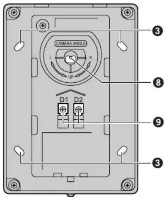
Front view Rear view
①Camera
- When a visitor presses the Call Button, the camera will turn on and an image of the visitor will be shown on the display of the monitor station.
②Microphone
③Screw hole (for fastening the door station to the wall or switch box)
④Speaker
⑤Call Button
●The Call Button is lit with a blue LED light while the power is on. ●A visitor can press this button to call the monitor station.
⑥Screw (to fasten the optional face panel in place)
⑦Water drain hole
● This hole allows rain water to drain. Do not cover it.
⑧Camera angle control lever
●The camera angle can be adjusted when installing the door station (page 7).
⑨ Terminal connector
Before installation
- To avoid malfunction or communication disturbances, do not install the door station in the following locations:
- Places where vibration or any other kind of impact occurs.
- Places where echoing is frequent.
- Places where a high concentration of dust, hydrogen sulfide, phosphorus, ammonia, sulfur, carbon, acid, or noxious fumes occur.
- Within 2 m (6'7") of a TV, microwave, personal computer, air conditioner or any other electrical device.
Standard installation position of the door station and camera range
Rear view


- The angle can also be adjusted to the left or upper left.
Upper/lower range
- Side view of the camera facing the front at 0°.

- Side view of the camera installed lower than the standard position and facing upward at 15°.

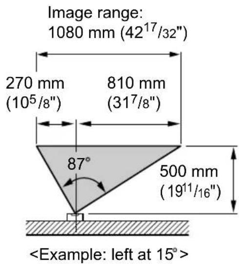
Left/right range
- Top view of the camera facing the front at 0°.

- Top view of the camera facing the left or right at 15°.
Note:
- The measurements and angles are for reference purposes and may vary depending on the environment.
- If a strong light is shining on the door station, the visitor's face may not be distinguishable. Do not place the door station in the following locations: – Where most of the background is the sky.
- Where the background is a white wall reflecting direct sunlight.
- Where direct sunlight will shine on the door station.
- Where echoing occurs, causing the unit to beep frequently. ● Make sure the back of the door station is not subject to water exposure.
Important:
- When the camera angle is set facing the upper left or upper right, the image may be slightly curved.
Wire type and distance
● Wire (between the monitor station and the door station): Type: General cable CAT-3 24 AWG Distance: Maximum 100 m (about 328 feet)
Switch box
- Switch box (to install the door station easily): Type: Gang box with conduit knockout Size: 3" x 2" (Depth: 1 1/2" over)
- 3 switch boxes are needed for installation.
Installing the door station
Important:
- An optional face panel must be purchased beforehand (page 5).
- On the bottom surface of the door station, there is a hole to allow water to drain. Do not cover it up when installing.
1 Connect the wire to the terminal connector.
- See page 9 for the wire type and distance.
- You can change the camera angle using the camera angle control lever. See page 7 for details.

2 Attach and fix the door station.
●Before drilling, see page 7 for installation location.

Note:
- Using the switch box (page 9) is easier to install.

3 Install the optional face panel as shown.
- Be sure to install the optional face panel (VL-GF001A) to avoid malfunction.
- Loosen the screw attached to the bottom of the door station.
- Set the hooks (①) on the face panel into the slots (②) and cover.
- Press and hold (③), while fasten by tightening the screw to fasten.

Cleaning
Use a soft, dry cloth when cleaning. For excessive dirt, wipe the unit with a slightly damp cloth.

Important:
- Do not use anything containing alcohol, polish powder, powder soap, benzine, thinner, wax, petroleum, or boiling water. Also do not spray with insecticide, glass cleaner, or hair spray. This could cause a change in color or quality.
Technical data about this product
Power supply *1: Standby: Approximately 5 V DC (2 mA)
At operation: Approximately 20 V DC (180 mA)
Dimensions: Approximate height 165 mm x width 115 mm x depth 51 mm
(6 1/2" x 4 1/2" x 2")
Mass (Weight): Approximately 225 g (0.5 lb.)
Operating environment: -10 °C to 50 °C (14 °F - 122 °F),
Up to 90% RH (Relative Humidity) non condensing
Installation method: Flush mount
External material: ABS (V-0)
Image pickup device: 1/4" CCD (0.25 megapixel)
Minimum subject
illumination: 1 lux within 500 mm (19
3/4") from the door station
*1 Supplied from the monitor station.
Note:
- Design and specifications are subject to change without notice.
- The pictures and illustrations in these instructions may vary slightly from the actual product.
FCC and Other Information
This device complies with Part 15 of the FCC Rules. Operation is subject to the following two conditions:
(1) This device may not cause harmful interference. (2) This device must accept any interference received, including interference that may cause undesired operation.
CAUTION:
Any changes or modifications not expressly approved by the party responsible for compliance could void the user's authority to operate this device.
NOTE:
This equipment has been tested and found to comply with the limits for a Class B digital device, pursuant to Part 15 of the FCC Rules. These limits are designed to provide reasonable protection against harmful interference in a residential installation. This equipment generates, uses, and can radiate radio frequency energy and, if not installed and used in accordance with the instructions, may cause harmful interference to radio communications. However, there is no guarantee that interference will not occur in a particular installation. If this equipment does cause harmful interference to radio or television reception, which can be determined by turning the monitor station off and on, the user is encouraged to try to correct the interference by one or more of the following measures:
– Reorient or relocate the receiving antenna. – Increase the separation between the equipment and receiver. - Connect the equipment into an outlet on a circuit different from that to which the receiver is connected. - Consult the dealer or an experienced radio/TV technician for help.
For your future reference
Date of purchase
Serial number (found on the rear of the unit)
Dealer's name and address
Dealer's telephone number
Attach your sales receipt here.
[ ]
L --- --- --- --- --- --- --- --- ---
Panasonic Consumer Electronics Company,
Division of Panasonic Corporation of North America
One Panasonic Way, Secaucus, New Jersey 07094, U.S.A.
Panasonic Puerto Rico, Inc.
San Gabriel Industrial Park, Ave. 65 de Infantería, Km. 9.5, Carolina, Puerto Rico 00985, U.S.A.
Copyright:
- This material is copyrighted by Panasonic Communications Co., Ltd., and may be reproduced for internal use only. All other reproduction, in whole or in part, is prohibited without the written consent of Panasonic Communications Co., Ltd.
- INSTALLATION AND OPERATION GUIDE
- THANK YOU FOR PURCHASING A PANASONIC DOOR STATION
- IMPORTANT INFORMATION
- INSTALLATION INTRODUCTIONS
- HELP
- GENERAL INFORMATION
- IMPORTANT SAFETY INSTRUCTIONS
- SAVE THESE INSTRUCTIONS
- ADDITIONAL SAFETY INFORMATION
- FOR BEST PERFORMANCE
- INCLUDED ITEMS
- OPTIONAL ITEM INFORMATION
- AVAILABLE OPTIONAL ITEMS
- LOCATION OF CONTROLS
- ①CAMERA
- ②MICROPHONE
- ④SPEAKER
- ⑤CALL BUTTON
- ⑦WATER DRAIN HOLE
- ⑧CAMERA ANGLE CONTROL LEVER
- ⑨ TERMINAL CONNECTOR
- BEFORE INSTALLATION
- STANDARD INSTALLATION POSITION OF THE DOOR STATION AND CAMERA RANGE
- UPPER/LOWER RANGE
- LEFT/RIGHT RANGE
- NOTE
- IMPORTANT
- WIRE TYPE AND DISTANCE
- SWITCH BOX
- INSTALLING THE DOOR STATION
- ATTACH AND FIX THE DOOR STATION
- INSTALL THE OPTIONAL FACE PANEL AS SHOWN
- CLEANING
- TECHNICAL DATA ABOUT THIS PRODUCT
- FCC AND OTHER INFORMATION
- CAUTION
- FOR YOUR FUTURE REFERENCE
- ATTACH YOUR SALES RECEIPT HERE
- COPYRIGHT
Brand : PANASONIC
Model : VL-GC003A
Category : Intercom