
VL-GM301A - Intercom PANASONIC - Free user manual and instructions
Find the device manual for free VL-GM301A PANASONIC in PDF.


| Product Type | Intercom Monitor Station |
| Model Number | VL-GM301A |
| Brand | Panasonic |
| Display | 3.5-inch color LCD |
| Power Supply | 24 V DC (from included AC adaptor) |
| Current Consumption | Standby: approx. 44 mA; Operation: approx. 450 mA |
| Video Output Level | 1 Vp-p, 75 Ω (NTSC color signal) |
| Dimensions (H x W x D) | 145 mm x 165 mm x 44 mm (5.75 in x 6.5 in x 1.75 in) |
| Weight | Approx. 600 g (1.32 lb) |
| Operating Environment | 0 °C to 40 °C, up to 90% RH (non-condensing) |
| Installation Method | Surface mount or flush mount (optional flush mount unit required) |
| External Material | Flame retardant ABS resin (panel: acrylic resin) |
| Compatible PBX Models | Panasonic KX-TA308, TA624, TA824, TA1232, TAW848, TD308, TD816, TD1232, TDA50, TDA100, TDA200 |
| Number of Cameras Supported | Up to 2 door stations (camera 1 and camera 2) |
| Talk Modes | Push-to-talk (PUSH) and Press-to-talk (HOLD) |
| Door Opener Support | Yes, up to 2 door openers |
| Group Function | Supports group A and B for calling and camera assignment |
| Ringer Tones | Selectable per camera (e.g., Bell1, Bell2) |
| Alarm Output | Adjustable from approx. 2 to 30 seconds |
| Monitoring Duration | Up to 1 minute per monitoring session |
| Conversation Time Limit | Approx. 1 min 30 sec (PUSH mode) / approx. 1 min (HOLD mode) |
| Cleaning Instructions | Use a soft dry cloth; avoid alcohol, benzene, thinner, wax, etc. |
| Accessories Included | Monitor station, wood screws, AC adaptor, power cord, power cable, BNC cable |
Frequently Asked Questions - VL-GM301A PANASONIC
User questions about VL-GM301A PANASONIC
0 question about this device. Answer the ones you know or ask your own.
Ask a new question about this device
Download the instructions for your Intercom in PDF format for free! Find your manual VL-GM301A - PANASONIC and take your electronic device back in hand. On this page are published all the documents necessary for the use of your device. VL-GM301A by PANASONIC.
USER MANUAL VL-GM301A PANASONIC
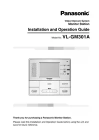
Installation and Operation Guide
Model No. VL-GM301A

Thank you for purchasing a Panasonic Monitor Station.
Please read this Installation and Operation Guide before using the unit and save for future reference.
Important Information
Important safety instructions .... 3
Additional safety information 4
For best performance .... 5
FCC and Other Information 6
Introduction and Installation
Included items....7
Optional item information 8
Compatible PBXs 8
Location of controls 9
Before installation 10
Precautions when connecting 11
Installing the monitor station 15
Using the unit
Connecting to a PBX 22
Before using the unit.... 23
On-screen Displays 23
Brightness setting / Talk volume setting 24
Answering a door call using the monitor station 25
Monitoring the outside 27
When connecting expansion units 28
Using by groups 30
Opening a door (Door Opener) 31
Menu setup
Monitor station/sub monitor station screen configuration 32
Display the menu screen and then make the settings 34
Setting the receive volume 36
Setting the ringer volume 37
Selecting the ringer 38
Selecting the PBX 40
Setting monitor station or sub monitor station into groups 41
Selecting a camera 42
Setting the talking method 44
Setting the alarm output time 45
Restoring settings to defaults 46
Help
Troubleshooting 47
Cleaning 48
General Information
Technical data about this product 49

CAUTION
RISK OF ELECTRIC SHOCK
DO NOT OPEN


The lightning flash with arrowhead symbol within an equilateral triangle is intended to alert the user to the presence of uninsulated dangerous voltage within the product's enclosure that may be of sufficient magnitude to constitute a risk of electric shock to persons.

The exclamation point within an equilateral triangle is intended to alert the user to the presence of important operating and maintenance (servicing) instructions in the literature accompanying the appliance.
Important safety instructions
1) Read these instructions. All the safety and operating instructions should be read before the appliance is operated. 2) Keep these instructions. The safety and operating instructions should be retained for future reference. 3) Heed all warnings. All warnings on the appliance and in the operating instructions should be adhered to. 4) Follow all instructions. All operating and use instructions should be followed. 5) Do not use this apparatus near water. For example, near a bathtub, wash bowl, kitchen sink, or laundry tub, in a wet basement, or near a swimming pool, and the like. 6) Clean only with dry cloth. Do not use liquid cleaners or aerosol cleaners. Use a dry cloth for cleaning. 7) Do not block any ventilation openings. Install in accordance with the manufacturer's instructions. Slots and openings in the cabinet are provided for ventilation and to ensure reliable operation of the product and to protect it from overheating. The openings should never be blocked by placing the product on a bed, sofa, rug, or other similar surface. 8) Do not install near any heat sources such as radiators, heat registers, stoves, or other apparatus (including amplifiers) that produce heat. This product should not be placed in a built-in installation such as a bookcase or rack unless proper ventilation is provided or the manufacturer's instructions have been adhered to.
9) Do not defeat the safety purpose of the polarized or grounding-type plug. A polarized plug has two blades with one wider than the other. A grounding type plug has two blades and a third grounding prong. The wide blade or the third prong are provided for your safety. If the provided plug does not fit into your outlet, consult an electrician for replacement of the obsolete outlet. 10) Protect the power cord from being walked on or pinched particularly at plugs, convenience receptacles, and the point where they exit from the apparatus. 11) Only use attachments/accessories specified by the manufacturer. 12) Unplug this apparatus during lightning storms or when unused for long periods of time. This will prevent damage to the product due to lightning and power-line surges. 13) Refer all servicing to qualified service personnel. Servicing is required when the apparatus has been damaged in any way, such as power-supply cord or plug is damaged, liquid has been spilled or objects have fallen into the apparatus, the apparatus has been exposed to rain or moisture, does not operate normally, or has been dropped.
Additional safety information
- Use only the power source marked on the unit. If you are not sure of the type of power supplied to your home, consult your dealer or local power company.
- Use only the specified AC adaptor.
- Do not tamper with the plug.
- Make sure the plug is securely inserted.
- Do not touch the plug with wet hands.
- Do not place objects on the power cord. Install the unit where no one can step or trip on the cord.
- To reduce the risk of electric shock, do not disassemble this unit. Take the unit to an authorized service center when service is required. Opening or removing covers may expose you to dangerous voltages or other risks. Incorrect reassembly can cause electric shock when the unit is subsequently used.
- Unplug this unit from power outlets and refer servicing to an authorized service center when the following conditions occur:
A. If smoke rises, or an unaccustomed noise or smell is discharged from the unit.
B. If metal objects have been dropped inside the monitor station.
- Do not put your ear(s) near the speaker, as loud sounds emitted from the speaker may cause hearing impairment.
- Only a qualified technician is allowed to connect a power cable to the unit. Contact an authorized service center.
- Do not make any wiring connections when the power supply is turned on.
- Never install wiring during a lightning storm.
- Do not connect a power cable other than the specified voltage.
- Do not connect the power cable to any terminal other than the one specified.
- When existing chime wires are used, it is possible that they contain AC voltage. Electric shock or unit damage could result. Contact an authorized service center.
- Never touch the inside of the monitor station. High voltage is present.
- Make certain when mounting the unit to any wall surface that the method used will hold the weight of the unit properly.
- If the wiring is outdoors, use a protection tube or a surge protector.
- If the wiring is underground, do not make any connections underground.
- WARNING – To Reduce The Risk Of Fire Or Electric Shock, Do Not Expose This Apparatus To Rain Or Moisture.
- WARNING – Unplug this unit from power outlets if it emits smoke, an abnormal smell or makes unusual noise. These conditions can cause fire or electric shock. Confirm that smoke has stopped and contact an authorized service center.
Note:
- This product has a fluorescent lamp that contains a small amount of mercury. It also contains lead in some components. Disposal of these materials may be regulated in your community due to environmental considerations. For disposal or recycling information please contact your local authorities, or the Electronics Industries Alliance: http://www.eiae.org
For best performance
- If a power failure occurs, the unit will not function.
- Do not place any object within 20 cm (8 inches) of the monitor station. This may cause communication errors or malfunction.

FCC and Other Information
This device complies with Part 15 of the FCC Rules. Operation is subject to the following two conditions:
(1) This device may not cause harmful interference. (2) This device must accept any interference received, including interference that may cause undesired operation.
CAUTION:
Any changes or modifications not expressly approved by the party responsible for compliance could void the user's authority to operate this equipment.
NOTE:
This equipment has been tested and found to comply with the limits for a Class B digital device, pursuant to Part 15 of the FCC Rules. These limits are designed to provide reasonable protection against harmful interference in a residential installation. This equipment generates, uses, and can radiate radio frequency energy and, if not installed and used in accordance with the instructions, may cause harmful interference to radio communications.
However, there is no guarantee that interference will not occur in a particular installation. If this equipment does cause harmful interference to radio or television reception, which can be determined by turning the equipment off and on, the user is encouraged to try to correct the interference by one or more of the following measures:
- Reorient or relocate the receiving antenna.
- Increase the separation between the equipment and receiver.
- Connect the equipment into an outlet on a circuit different from that to which the receiver is connected.
- Consult the dealer or an experienced radio/TV technician for help.
Included items
①
②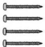
③
④
⑤
⑥
⑦
| No. | Item Quantity Notes | ||
| 1 | Monitor station | 1 ---- | |
| 2 | Wood screws | 4 | For the monitor station. 4 mm × 35 mm (3/16" × 13/8") |
| 3 | AC adaptor | 1 | Enclosed in the AC adaptor case. |
| 4 | Wood screws 2 | For the AC adaptor case. 4 mm × 16 mm (3/16" × 5/8") | |
| 5 | Power cord | 1 ---- | |
| 6 | Power cable | 1 | ---- |
| 7 | BNC cable | 1 | ---- |
Monitor Station:
The Monitor Station is a central management device that allows operation of the Door Station, Door Opener, PBX, etc. and controls the entire system.
This system requires one Monitor Station to operate.
Optional item information
Available optional items
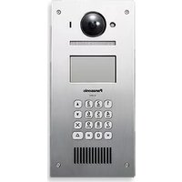
- Door station (VL-GC001A, VL-GC002A)
- Sub Monitor station (VL-GM001A)
- Flush mount unit (VL-GW001A)
Compatible PBXs
This unit is compatible with the following Panasonic PBXs*1:
- KX-TA308
- KX-TA624
- KX-TA824
- KX-TA1232
- KX-TAW848 (Ver2.0 or later)
- KX-TD308
- KX-TD816
- KX-TD1232
- KX-TDA50 (Ver2.0 or later)
- KX-TDA100 (Ver2.01 or later)
- KX-TDA200 (Ver2.01 or later)
*1 As of March, 2005. Consult your dealer for a current list of compatible PBXs.
Location of controls
Front view
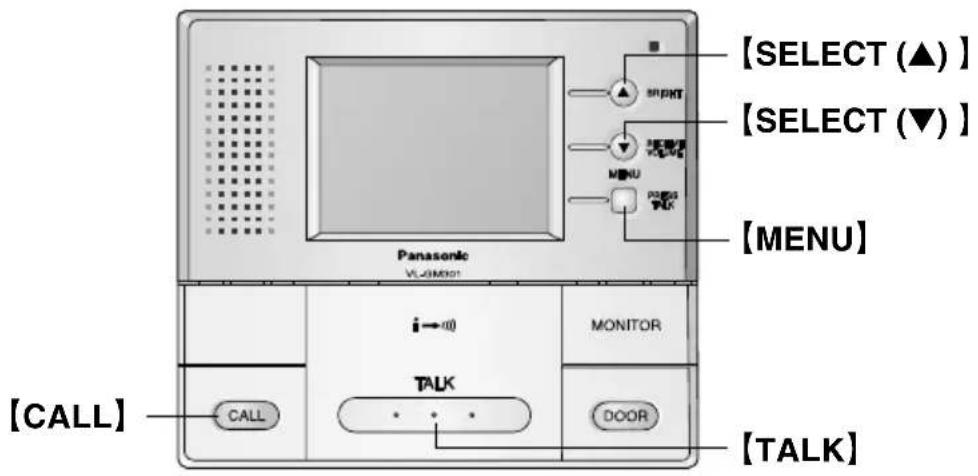
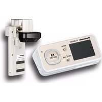
① Display (3.5-inch color LCD screen) ② Microphone
- Speak into the microphone when talking to a visitor.
③ SELECT (▲) button / BRIGHT button ④ SELECT (▼) button / RECEIVE VOLUME button ⑤ MENU button / PRESS TALK button ⑥ MONITOR button
- Allows you to monitor the sound and camera image from the door station. (Page 27)
⑦ DOOR button
- Allows you to open the door. (Page 31)
⑧ TALK button
- To answer a door call and/or speak to the visitor. (Page 25)
⑨ CALL button
- To call another monitor unit. (Page 28)
⑩ Speaker
⑪ Video output connector
- This terminal is used for connecting the monitor to a standard TV for viewing images. (Sound cannot be output.)
* Ventilation holes are located at the bottom. (Do not cover these.)
Before installation
To avoid malfunction or communication disturbance, do not install the monitor station in the following locations:
- Places where vibration or any other kind of impact occurs.
- Places where echoing is frequent.
- Places where a high concentration of dust, hydrogen sulfide, phosphorus, ammonia, sulfur, carbon, acid, or noxious fumes occur.
- Within 2 m (6'7") of a TV, microwave, personal computer, air conditioner or any other electrical device.
The monitor station and AC adaptor are for indoor use only.
Do not use it outdoors, otherwise it may malfunction.
- Use the flush mount unit (sold separately) when installing the monitor station into a wall.
- Refer to the Installation and Operation Guide that is included with the flush mount unit for details on installing the flush mount unit.
Standard installation position of the monitor station
Place the monitor station in a location so that your eyes are the same height as the center of the display.
Note:
- In areas surrounded by high electrical field, disturbance may occur in the monitor station's image or sound.
- Be sure to install the monitor station more than 5 m (16'5") away from the door station.
- Please check that there is a partition of a wall etc. between a monitor station and sub monitor station and attach them.
- Do not place any objects within 20 cm (8 inches) of the monitor station. This may cause communication errors or malfunction.
- Do not install the monitor station inside a wall, without using the flush mount unit.
Precautions when connecting
The following points should be observed at all times.
Be sure to observe the following, otherwise operating problems may occur or the quality of the images and sound may be adversely affected.
- Use the specified connection cables.
- Do not connect a door station in relay.
![graph LR A["<Door station>"] -->|Incorrect| B["<Door station>"] B --> C["<Monitor station>"]](/content/2026/05/1074749/images/500c3ca8171d39b74784ec0979a859d5a93adc956f670e2f0e644a7de14700ec.jpg)
- If using an existing cable, disconnect the monitor station from the 120 V AC power supply and check the cable length and the loop resistance.
![graph TD A["Door station"] --> B["Sub Monitor station"] B --> C["General cable CAT-3 24AWG"] C --> D["Up to 100 m (328 feet)"] C --> E["Loop resistance: 18.4 [Ω"] or less] F["Sub Monitor station"] --> G["General cable CAT-3 24AWG"] G --> H["Up to 100 m (328 feet)"] G --> I["Loop resistance: 18.4 [Ω"…](/content/2026/05/1074749/images/9f7eb9d9146776c1c6686a06882757c2df9edc6c9c13b53cd5ef49862f4b5e40.jpg)
- Connect one end and measure at the other end using a circuit tester.

- If branch wires are connected and they adversely affect images and sound or prevent operation, remove the branch wires from their source.
![graph LR A["Door station"] --> B["Monitor station"] B --> C["Sub Monitor station"] A --> D["Branch wires (Incorrect)"] B --> E["Branch wires (Incorrect)"]](/content/2026/05/1074749/images/b91da5951a576cc56671fc84f10faeb314f2008f1b6051159d21bcdb4ad1c49e.jpg)
- When you experience a problem with the audio or video on a sub monitor station connected to a monitor station, please terminate unused pairs of wires to prevent noise from being introduced into the monitor station. This can be accomplished by doubling the wire pairs or using a resistor on each unused wire pair end to create a closed loop.
![graph LR A["<Monitor station"] --> B["<Sub Monitor station"] B --> C["Unused wires (Incorrect)"] B --> D["Unused wires (Incorrect)"] C --> E["Connection cable"] D --> F["Connection cable"] E --> G["Connect the excess wire"] F --> H["Excess wire"] G --> I["120 Ω"] H --> J["120 Ω"]](/content/2026/05/1074749/images/0a6a6d285700153af76cdcaa049d9a567dc75583e20049094ed7210c0b1925a7.jpg)
NOTE:
- Compatibility can vary depending on installation environment and wiring conditions, so please make a selection which corresponds with your situation.
- Do not connect sub monitor station using distributed wiring. - Make sure to run cable by daisy chain wiring method.
![graph TD A["Monitor station"] -->|Incorrect| B["Sub Monitor station"] B --> C["Sub Monitor station"]](/content/2026/05/1074749/images/e127bfb842468cb45d5cee800bb0dc13456d8be604c76ac93ad620f0c36818fb.jpg)
- Do not connect other sub monitor station in relay along the same route. - Make sure NOT to run the cable in pipes containing other cables. All cable/wire must be segregated by individual pipes.
![graph TD A["Monitor station"] --> B["Same route (Incorrect)"] B --> C["Sub Monitor station"] B --> D["Sub Monitor station"]](/content/2026/05/1074749/images/1fc7b6f3a6c1b56a2be81f4e14d2af92e5852d7f71c659aa86dfa28526ed323b.jpg)
Wiring schematic diagram![graph TD A["Door station1 VL-GC002A or VL-GC001A"] --> B["D1 D2"] B --> C["Door station2 VL-GC001A or VL-GC002A"] C --> D["D1 D2"] D --> E["Video output conector"] E --> F["TV / Monitor"] F --> G["TV / Monitor"] G --> H["AC adaptor"] H --> I["PBX (Example: KX-TDA50)"] I --> J["Chime"] I --> K["Chime…](/content/2026/05/1074749/images/ea2f4f429d1c63292dc62d1b8cce6776a5aab1d370edbef8901bfe468869f246.jpg)
NOTE:
- This door opener and chime wiring schematic diagram is only an example.
Refer to the wiring instructions provided with your door opener, chime, and PBX for details.
- Refer to the technical data on page 49 when connecting to a door opener and chime.
- All connections are non-polar, except the V0+ and V0- terminals.
- After connecting the BNC cable with a BNC connector, slide the protective cover over the connector to protect it.
Power cable/wire type and distance
- Power cable (between the monitor station and the AC adaptor):
Type: Ø 1.2 Fire alarm cable 16 AWG
Distance: Maximum 30 m (about 98 feet)
- Wire (between the monitor station and the door station):
Type: General cable CAT-3 24 AWG
Distance: Maximum 100 m (about 328 feet)
Loop resistance: 18.4 Ω or lower
- Wire (between the monitor station and the last sub monitor station):
Type: General cable CAT-3 24 AWG
Distance: Maximum 100 m (about 328 feet)
Loop resistance: 18.4 Ω or lower
- Wire (between the monitor station and PBX):
Type: General cable CAT-3 24 AWG
Distance: Maximum 100 m (about 328 feet)
Installing the monitor station
1 Remove the monitor station from the box, and then remove the padding material from between the front case and the bottom case.
- The front case and the bottom case are not joined together, so be careful not to drop them when taking them out of the box.

2 Remove the terminal cover.

3 Install the bottom case to a wall using the wood screws (4 mm x 35 mm, 3/16" x 1-3/8").
- Before drilling, see page 10 for installation location.


4 Attach the power cable to the terminal. See page 21 for details on how to attach the power cable.
- If you want to use your own power cable, see page 14 for the type and distance.

5 Attach the wires that connect to the door station to the terminal. See page 21 for details on how to attach the wires.
- See page 14 for the wire type and distance. - See the wiring schematic diagram on page 14.

6 Remove the sheet covering the connector. Next, after installing the terminal cover in the bottom case, attach the connector by tightening the connector screw. Next, align the lower portion of the bottom case with the lower portion of the front case and press on the panel area just above the screen until the tabs lock in place.


- Check that there are no scraps from the board or other debris in the connector before installing it.
■ Remove the front case from the bottom case
① While pushing the tabs at the top of the front case, pull the top of the front case forward to disengage the front tabs one by one, and then pull the top of front case forward to remove it.


② Remove the connector screw, and then remove the connector.


Do not pull the wire when removing the connector.
7 Take out the AC adaptor and the DC terminal from the case.
- Push the arrow mark on the front case, then release from the rear case. •Take out the cardboard and wood screws. The wood screws are necessary when attaching the AC adaptor and the DC terminal to a wall (page 20).
![graph TD A["Arrow mark"] --> B["Pinning System"] B --> C["DC terminal with cable"] C --> D["AC adaptor"]](/content/2026/05/1074749/images/e302f097547d81218d96d2c4f90cc4fe3557c9bc3b8e94d8df6302f71186f73f.jpg)
8 Connect the power cable to the DC terminal, the power cord to the AC adaptor, then connect the power cord to the AC outlet (100 V – 240 V, 50 Hz / 60 Hz).
- Be sure to connect the power cable to the 2 holes on the left side of the DC terminal.
- For details on how to attach the power cable, see page 21.

9 Attach the DC cord to the clamp on the rear of the DC terminal.
- This will help to avoid the DC cord to disconnect from the DC terminal.

To attach the AC adaptor and the DC terminal to a wall
By placing the AC adaptor and the DC terminal in the case and mounting the case to the wall, you can protect the AC adaptor and the DC terminal from tampering and exposure.
Note:
- Disconnect the DC cord from the clamp on the rear of the DC terminal beforehand. See step 9 on page 19 for details. • Take out the cardboard and wood screws from the AC case beforehand.
1 Attach the rear part of the case to a wall using the wood screws (4 mm x 16 mm, 3/16" x 5/8").

2 Pack the AC adaptor and DC terminal as shown.
① Pack the AC adaptor in the rear case. - Be sure to run the power cord through the power cord hole. ② Pack the DC cord in the rear case. - Be sure to bundle the DC cord so that it will not touch the bottom of the case. ③ Pack the DC terminal in the rear case. - Be sure to run the wires through the wire hole, then under the wire rib.

3 Attach the front of the case.

Note:
- To open the case again, push the bottom of the front case, then release from the rear case.

To attach the power cable
Monitor station
DC terminal
- While pressing on the button hard with a pointed object such as a screwdriver, insert the power cable into the terminal connector.
- To disconnect the power cable, press on the button hard while pulling out.
- To attach an optional power cable, cut off about 12 mm (1/2") of the cable cover (①), then push in firmly until the end of the cable is securely inserted into the power connection terminal (②).
①
② Power cable cross section Correct Incorrect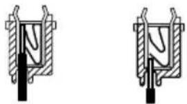
To attach the wires

- Strip off the wire cover so that about 9 mm (3/8") of the wire is exposed.
- While pressing on the button with a pointed object such as a screwdriver, insert the wire into the terminal connector.
- To disconnect a wire, press on the button while pulling out.
Connecting to a PBX
Connecting to a PBX allows you to answer door calls from any telephone. See page 14 for wiring information.
Please use only a Panasonic PBX. See page 8 for the PBX model list that is compatible and other optional hardware.
Important:
- At first, set "PBX SELECT" to "ON" in the menu settings. (Page 40)

- If you answer a call from the door station with a PBX extension, the camera image from the door station will be displayed at the monitor station. If the monitor station user tries to answer the call, a beep will sound. The display will turn off when the conversation has ended or when the conversation has continued for more than 3 minutes.
- If you answer a call from the door station with the monitor station, the call will continue to ring at the PBX for about 15 to 30 seconds. If the PBX user answers the call while the call is still ringing, the door station user, the monitor station user, and the PBX user can speak together.
Before using the unit
All the safety and Installation and Operation Guide should be read before the appliance is operated. All operating and use instructions should be followed.
On-screen Displays
The following character displays and icon displays appear on the screen of the monitor station/sub monitor station.

■ When no images are being displayed
● The calling/talking status and the call operations for the indoor unit are shown as icons.


If an indoor unit receives a call, the characters flash.
The characters light steadily while talking between indoor units is in progress.
■ When images are being taken
● The talking status is shown using characters and icons. (Top right of screen.)

These light steadily when carrying out a hands-free conversation.
-))) shows the direction of talking. - The conversation method indicated may also change as a result of ambient noise. - If you change to a press-to-talk conversation, the icon will change to "PT".
● The camera in use is shown using characters. (Top right of screen.)
CAM1 CAM2
When watching what is happening outside the door, the display lights steadily. When there is a call from a door station, the display flashes.
- When talking with the door station via PBX: PBX1 PBX2
- If a call operation overlaps in timing, this is shown using icons.
(Bottom right of screen.)

Lights steadily when there is a call from another door station.
Lights steadily when there is a call to or from an indoor unit.

Note:
- Indoor unit refers to the monitor station and sub monitor station.
Brightness setting / Talk volume setting
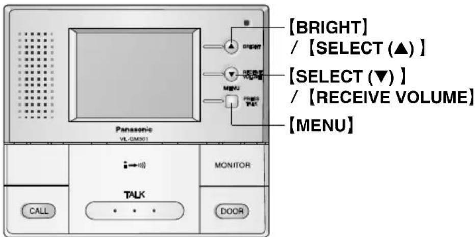
■ Brightness setting
(Default setting is "0".)
You can set the brightness for images that are being displayed from a door station (when talking to a visitor or monitoring the scene outside the door).
1 While images are appearing on the screen. 2 Press [BRIGHT (▲)] . 3 Press 【SELECT (▲ / ▼)】 to select the brightness.
The brightness can be set in 5 steps (“-2” to “+2”).
- The screen brightness becomes darker when the setting changes in the [-] direction, and brighter when the setting changes in the [+] direction.
4 When the setting is complete, press 【MENU】.
■ Receive volume setting (Default setting is "MID".)
You can set the volume while talking with someone at a door station or monitor station and sub monitor station.
1 While talking to someone at a door station. 2 Press【RECEIVE VOLUME (▼)】. 3 Press 【SELECT (▲ / ▼)】 to select the receive volume.
The receive volume can be set in 3 steps ("LOW" to "HIGH").
- The receive volume becomes lower when the setting moves towards "LOW", and higher when the setting moves towards "HIGH".
4 When the setting is complete, press 【MENU】.
- The receive volume setting can also be set using the menu screen. (Page 36)
Note:
- If you do not carry out any operations for about 5 seconds, the brightness setting and receive volume setting will be completed. When this happens, the setting will be maintained until the current conversation or image display is finished, and then it will return to the previous setting.
Answering a door call using the monitor station
There are 2 ways to answer a door call using the monitor station. Select the desired mode by changing the “COMMUNICATION” setting in the menu settings. (Page 44)
Important:
- When speaking with a caller, speak in turns. If you and the caller speak at the same time, you will not hear each other.
![Panasonic VL-GM301 [BRIGHT] BRIGHT MENU PRESS TALK [TALK] [PRESS TALK] MONITOR CALL DOOR](/content/2026/05/1074749/images/b69065b42b5d26ec6dc63926e5419126503d1cdf3c85e8c42f3c35ce89decb23.jpg)
Available answer modes
■ 【PUSH】 mode (Push to talk mode)
1 When a call is received from the door station, press 【TALK】. 2 Speak to the visitor. 3 To end the conversation, press 【TALK】. - The display will turn off.
Note:
- If the door station is installed in a noisy environment, [PUSH] mode may not function properly.
■ 【HOLD】 mode (Press to talk mode)
1 When a call is received from the door station, press and hold [TALK] to speak to the caller. - A beep will sound and the "PT" will light. 2 To listen to the visitor, release [TALK]. 3 To speak again, press and hold [TALK]. 4 To end the conversation, tap [TALK].
- Make sure you speak to the caller only while pressing [TALK] and release [TALK] when you have stopped speaking so that the caller can speak to you.
Note:
- Make sure you are within about 50 cm (20 inches) of the monitor station.
- While the display is on, you can press [BRIGHT] to select the desired brightness.
- If you do not answer a door call within 30 seconds, the display will turn off. If you press [TALK], the display will turn on again, and you can talk to the visitor.
- The conversation will be automatically disconnected in about 1 minute and 30 seconds (about 1 minute in [HOLD] mode). To resume the conversation, press [TALK].
- At night or when there is not enough lighting in the doorway, the display will be shown in black and white.
- Please press [TALK] when you want to change to [HOLD] mode in [PUSH] mode. "PT" will be displayed in LCD and it becomes [HOLD] mode. It returns to the setting of [PUSH] mode after end of talk.
Monitoring the outside (The procedure is the same for a sub monitor station.)
You can monitor the sound and camera image from the door station for up to 1 minute at a time.
![Panasonic VL-GM301 [BRIGHT] BRIGHT MENU PUBG PLC i←○ MONITOR [TALK] CALL [MONITOR] DOOR [TALK]](/content/2026/05/1074749/images/f8e536ff360126e602974c34d6cef334f9d7972a34eb39a631b705b4a73b5cad.jpg)
1 Press [MONITOR].
- The outside image will be shown on the display, and the outside sound will be heard. The inside sound will not be heard at the door station.
- If necessary, press [BRIGHT] to select the desired brightness. (Page 24)
■ If [MONITOR] on another monitor station and sub monitor station is pressed while you are viewing the scene outside the door ...
- The images will disappear, and the images will appear and sound will be heard at the other monitor station and sub monitor station. (Last button pressed has priority)
■To switch camera images on the monitor screen ...
The cameras switch each time 【MONITOR】 is pressed, and the images from the currently-selected camera number will appear on the screen.
![graph TD A["Camera 1 Camera 2"] --> B["Unconnected cameras are skipped"] C["No images"] --> A](/content/2026/05/1074749/images/6c7a8a4dc4a58dbcbfb440fca254ef96b42d76a37f021ec4d316242877d1680a.jpg)
2 To end monitoring, press 【MONITOR】.
- Even if you do not press 【MONITOR】, monitoring will automatically end in about 1 minute.
Note:
- While you are monitoring, calls from the door station will not be heard. • To talk to the visitor while monitoring, press 【TALK】.
When connecting expansion units
- While one monitor station and sub monitor station is being used, other monitor station and sub monitor station cannot be used.
- Monitor station and sub monitor station can be divided into groups and be called by group. (Pages 30, 41)
■ When talking between monitor station and sub monitor station (Press-to-talk cannot be used)
1 Press [CALL]. 2 Press one of the buttons to the right of the screen in accordance with the screen display. After the calling tone sounds, make the call. 3 Wait for an answer, and then talk. 4 When the conversation is finished: Press [TALK].
A short BEEP will tone. Press [TALK] and then talk. - The conversation will end even if 【TALK】 on the sub monitor station is pressed.
- If there is no answer within 1 minutes after you call, the call will be canceled.
If the following happens:
- When you call another unit, the message "OTHER INTERCOM IS USING IT" is displayed and a series of short beeps are heard. •A call comes from a door station while you are talking.
The other unit is being used. Wait a while and then call again.
The other unit is being used. Wait a while and then call again.
A ringer tone will be heard, so you can press [TALK] to end your conversation, and then press [TALK] again to talk with the person at the door station.
■ To transmit a conversation with someone at a door station to another room
1 While talking with someone at the door station. 2 Press [CALL]. - When you press the Indoor 【CALL】, the conversation with the person at the door station will be disconnected. 3 Press one of the buttons to the right of the screen in accordance with the screen display. After the calling tone sounds, make the call. 4 Wait for an answer, and then talk. 5 When the conversation is finished: Press [TALK].
■ Screen display and call buttons when the Indoor 【CALL】 is pressed

A short BEEP will tone. Press 【TALK】 and then talk. •The conversation will end even if 【TALK】 on the sub monitor station is pressed.
6 Press [TALK] and then talk to the person at the door station. 7 When the conversation is finished: Press [TALK].
Using by groups

■ Settings before use
● Monitor station and sub monitor station settings (Default settings are all “Group A”.)
Make the settings separately for each monitor station and sub monitor station using the indoor group settings in the menu. (Page 41)
- Group A and group B cannot both be used at the same time.
● Camera settings (Default settings are all "ON".)
Make the settings separately for each monitor station and sub monitor station by selecting the cameras in the menu. (Pages 42, 43)
■ When calling the monitor station and sub monitor station
(The procedure is the same for a sub monitor station.)
After pressing [CALL] ...
Press one of the buttons to the right of the screen in accordance with the screen display.
(After the calling tone sounds, make the call.)

- Calling tone
Same group: Two beeps (approximately 2 seconds) Other group: Arpeggio (approximately 3 seconds)
- If you call both groups together, the tones for both groups will sound.
■ Calling from a door station
When the Ringer button at a door station is pressed ...
- If the call is from door station 1
- The call will be transferred to the monitor station and sub monitor station that have camera 1 set to "ON" and talking will be possible.
- If the call is from door station 2
- The call will be transferred to the monitor station and sub monitor station that have camera 2 set to "ON" and talking will be possible.
Opening a door (door opener)
You can open the door using the monitor station and sub monitor station (a separate door opener is required).

1 While the display is on, press and hold 【DOOR】.
- Up to 2 door openers may be connected. (Page 14) When the monitor station receives a call from door station 1, pressing 【DOOR】 with the door station 1 image displayed activates the opener of door station 1. Likewise, if the call is from door station 2, pressing 【DOOR】 activates the opener of door station 2.
Note:
• See page 14 for wiring information.
Monitor station/Sub Monitor station screen configuration
(The displays shown for each screen are the default displays.)
![【MENU】 PENNSATE PLK MOUNTER CALL + - + - [+] + - + - [+] + - + - [+]](/content/2026/05/1074749/images/4a6de0f5c18f250faf7ee323cb3cd947f58f0e8df89ccef432dc24d8eba1b003.jpg)
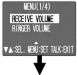
When 【MENU】 is pressed, the MENU (1/4) screen is displayed.
After this, follow the instructions appearing on the screen to carry out the various operations and settings.
- Refer to the reference pages for each screen for details.
MENU (1/4) screen (Pages 36 – 37)
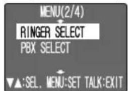
MENU (2/4) screen (Pages 38 – 40)
MENU (3/4) screen (Pages 41 – 44)

MENU (4/4) screen (Pages 45 – 46)

RECEIVE VOLUME (Page 36)
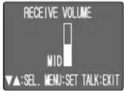
- The sub monitor station does not have a "RINGER SELECT" and "PBX SELECT" setting.
GROUP SETUP (Page 41)

CONTACT CLOSURE (Page 45)

■Sub Monitor Station menu screen
- The sub monitor station does not have a "RINGER SELECT" and "PBX SELECT" setting.


![graph TD A["RINGER VOLUME (Page 37)"] --> B["RINGER SELECT (Pages 38, 39)"] B --> C["CAMERA SELECT (Pages 42, 43)"] B --> D["PBX SELECT (Pages 40)"] C --> E["CAMERA SELECT (Pages 46)"] C --> F["COMMUNICATION (Page 44)"] E --> G["DOSE IT RETURN TO INITIAL SETTING? YES NO"] E --> H["SELECT ON OFF"] E…](/content/2026/05/1074749/images/19766be52e18241596c4b8cf34c8f3dbc456913f2b1b0d2259c924ff3618beeb.jpg)
Display the menu screen and then make the settings.

3 ■ Moving the cursor
Each time you press 【SELECT (▼)】, the cursor moves down. Each time you press 【SELECT (▲)】, the cursor moves up.
●When the cursor is at the lowest row or the highest row, the menu screen will change when you press 【SELECT (▼/▲)】 again.
![graph TD A["MENU(1/4)<br>RECEIVE VOLUME<br>RINGER VOLUME<br>▼▲:SEL. MENU:SET TALK:EXIT"] -->|press["SELECT (▼)"].| B["MENU(2/4)<br>RINGER SELECT<br>PBX SELECT<br>▼▲:SEL. MENU:SET TALK:EXIT"] C["MENU(2/4)<br>RINGER SELECT<br>PBX SELECT<br>▼▲:SEL. MENU:SET TALK:EXIT"] -->|press["SELECT (▲)"].| D["MENU…](/content/2026/05/1074749/images/525373c9d8805c27cc1cef2bbda4b051c8a44ebbdcf27cb67ee931c4730c1a16.jpg)
4 Move the cursor to the desired item and then press 【MENU】.
5 ■ Make the setting
● RECEIVE VOLUME : page 36 ● RINGER VOLUME : page 37 ● RINGER SELECT : pages 38, 39 ● PBX SELECT : page 40 ● GROUP SETUP : page 41
● CAMERA SELECT : pages 42, 43 ● COMMUNICATION : page 44 ● CONTACT CLOSURE : page 45 ● INITIALIZATION : page 46

Once the setting is complete, press 【MENU】. (The display will return to the menu screen.)
- For some screens, move the cursor to "BACK" and then press 【MENU】 to return to the menu screen.
• To make another setting, repeat steps 3 to 6.

Cursor Press【SELECT (▼)】 to move the cursor to "MENU EXIT".

Press 【MENU】.
- You can cancel (end) a menu setting by pressing [TALK] while making the menu setting.
Note:
- If you do not carry out any operation for approximately 5 minutes while a menu screen/setting screen is displayed, the screen will disappear automatically and the setting will end.
- Some settings will return to the previous settings.
- If a call comes from a door station or from the monitor station and sub monitor station while you are making a menu setting, the menu setting will automatically end.
Setting the receive volume (Default setting is "MID".)
This sets the receive volume for the door station and the monitor station or sub monitor station.

Press [MENU].
(The "MENU (1/4)" screen will be displayed.)
![2 RECEIVE VOLUME MID ▼▲:SEL. MENU:SET TALK:EXIT Check that the cursor is positioned at "RECEIVE VOLUME", and then press [MENU]. (The "RECEIVE VOLUME" screen will be displayed.)](/content/2026/05/1074749/images/1c2d8e9e3ce50f331f7fec589574895846ad76f1a7cff4d80f4f361d0bb88a44.jpg)
3 Press【SELECT (▲/▼)】to adjust the receive volume.
- The setting can be made in 3 steps from "LOW" to "HIGH".
![MENU (1/4) RECEIVE VOLUME RINGER VOLUME ▼▲:SEL. MENU:SET TALK:EXIT Once the receive volume setting has been made, press [MENU]. (The display will return to the "MENU (1/4)" screen.)](/content/2026/05/1074749/images/1d100a6874213b8e0ca383e9558e18f663074dd80f21e4bffb72ccfc81e4a9b0.jpg)
5 ■ To continue making further settings ...
Move the cursor to the desired item, and press 【MENU】. (Refer to step 5 on page 35.)
■To complete the settings ...

Press 【SELECT (▼)】 to return to the "MENU (4/4)" screen, and then move the cursor to "MENU EXIT" and press 【MENU】.
Setting the ringer volume (Default setting is "HIGH".)
This sets the ringer volume for the door station and the monitor station or sub
monitor station.

Cursor
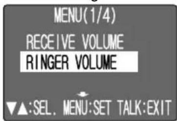
Press [MENU].
(The "MENU (1/4)" screen will be displayed.)
2

Press 【SELECT (▼)】 to move the cursor to "RINGER VOLUME".
3
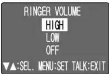
Press [MENU].
( The "RINGER VOLUME" screen will be displayed.)
4 Press [SELECT (▲/▼)] to adjust the ringer volume.
- The setting can be made in 3 steps from "OFF" to "HIGH".
5
Once the ringer volume setting has been made, press 【MENU】.
( The display will return to the "MENU (1/4)" screen.)
6 ■ To continue making further settings ...
Move the cursor to the desired item, and press 【MENU】.
(Refer to step 5 on page 35.)
■To complete the settings ...

Press 【SELECT (▼)】 to return to the “MENU (4/4)” screen, and then move the cursor to “MENU EXIT” and press 【MENU】.
Selecting the ringer
(Default settings are "CAMERA1: BELL1" and "CAMERA2: BELL2".)
This selects the ringer tone for CAMERA1 and CAMERA2.
![[SELECT (▲)] [SELECT (▼)] [MENU] Panasonic V1-05001 MONITOR CALL TALK DOOR](/content/2026/05/1074749/images/b5f9b15f48d76ef09538af1248b721725b83bd76019f1bf43e87782aa8e28c96.jpg)
1
Cursor
Press [MENU].
(The "MENU (1/4)" screen will be displayed.)
2
Press [SELECT (▼)] to move the cursor to "RINGER SELECT".
3
Press [MENU].
(The "RINGER SELECT" screen will be displayed.)
4
Press [SELECT (▲/▼)] to move the cursor to the camera for the ringer tone you would like to select.
5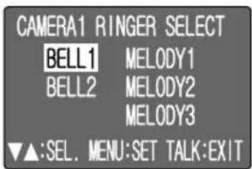
Press [MENU].
(The "RINGER SELECT" screen for the
corresponding
camera will be displayed.)
6. Press [SELECT (▲/▼)] to move the cursor to the tone you would like to select.
7
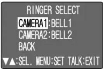
Press [MENU].
•The selected ringer will sound.
(The display will return to the "RINGER SELECT" screen.)
8 To select ringer tone, repeat steps 4 to 7.
9

Once you have selected the ringer tone, press 【SELECT (▼)】 to move the cursor to "BACK".
10

Press [MENU].
(The "MENU (2/4)" screen will be displayed.)
11■ To continue making further settings ...
Move the cursor to the desired item, and press [MENU].
(Refer to step 5 on page 35.)
■To complete the settings ...

Press 【SELECT (▼)】 to return to the "MENU (4/4)" screen, and then move the cursor to "MENU EXIT" and press 【MENU】.
Selecting the PBX (Default setting is "ON".)
This selects the PBX for door calls from any telephone.

Cursor
Press [MENU].
(The "MENU (1/4)" screen will be displayed.)
2

Press [SELECT (▼)] to move the cursor to "PBX SELECT".
3

Press [MENU].
(The "PBX SELECT" screen will be displayed.)
4
Press [SELECT (▲/▼)] to move the cursor to "ON" or "OFF".
- ON: PBX is used. OFF: PBX is not used.
5

Once the PBX setting has been made, press [MENU].
(The display will return to the "MENU (2/4)" screen.)
(This completes the setting.)
6
■ To continue making further settings ...
Move the cursor to the desired item, and press 【MENU】. (Refer to step 5 on page 35.)
■ To complete the settings ...
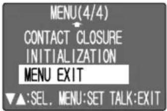
Press 【SELECT (▼)】 to return to the “MENU (4/4)” screen, and then move the cursor to “MENU EXIT” and press 【MENU】.
Setting monitor station or sub monitor station into groups (Default setting is "Group A".)
Use this when you would like to separate monitor station or sub monitor station into
groups for use.
Cursor
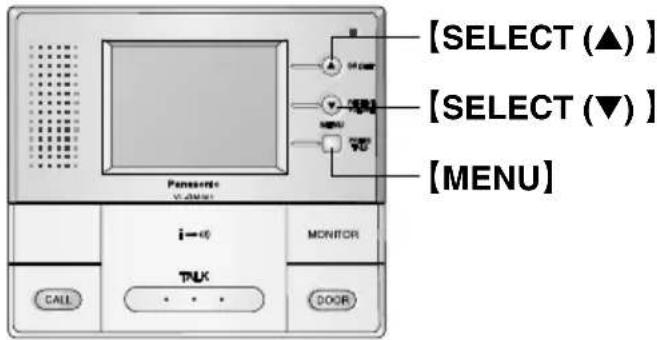
Press 【MENU】.
(The "MENU (1/4)" screen will be displayed.)
2

Press 【SELECT (▼)】 to display the “MENU (3/4)” screen, and then move the cursor to “GROUP SETUP”.
3

Press 【MENU】.
(The "GROUP SETUP" screen will be displayed.)
4
to move the cursor to the group you would like to select.
5

Once the group setting has been made, press 【MENU】. (The display will return to the “MENU (3/4)” screen.)
6
■ To continue making further settings ... Move the cursor to the desired item, and press 【MENU】. (Refer to step 5 on page 35.)
■To complete the settings ...

Press 【SELECT (▼)】 to return to the “MENU (4/4)” screen, and then move the cursor to “MENU EXIT” and press 【MENU】.
Selecting a camera (Default setting is for all cameras to be "ON".)
This selects the camera (CAMERA1 or CAMERA2) to be used for each group.
![[SELECT (▲)] [SELECT (▼)] [MENU] Panasonic V1-0301 MONITOR TALK CALL DOOR](/content/2026/05/1074749/images/fdac876b50cce8e155a9315ca86fac7b4c289e12044df7bce159e07e3ef7ea85.jpg)
1

Cursor
Press [MENU].
(The "MENU (1/4)" screen will be displayed.)
2

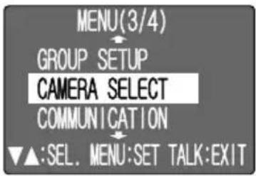
Press [SELECT (▼)] to display the "MENU (3/4)" screen, and then move the cursor to "CAMERA SELECT".
3

Press [MENU].
(The "CAMERA SELECT" screen will be displayed.)
4. Press [SELECT (▲/▼)] to move the cursor to the group you would like to select.
5
Press [MENU].
(The "CAMERA SELECT" screen for the corresponding camera will be displayed.)
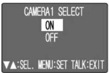
6. Press [SELECT (▲/▼)] to move the cursor to "ON" or "OFF".
- ON: Camera is used. • OFF: Camera is not used.
7

Press [MENU].
(The "CAMERA SELECT" screen will be displayed.)
(This completes the setting.)
8 To select another camera, repeat steps 4 to 7.
9

Once you have selected the camera, press
【SELECT (▼)】 to move the cursor to "BACK".
10
Press [MENU].
(The "MENU (3/4)" screen will be displayed.)
11 ■ To continue making further settings ...
Move the cursor to the desired item, and press [MENU].
(Refer to step 5 on page 35.)
■To complete the settings ...
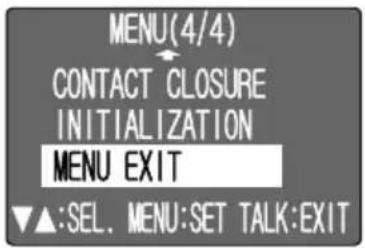
Press 【SELECT (▼)】 to return to the "MENU (4/4)" screen, and then move the cursor to "MENU EXIT" and press 【MENU】.
Setting the talking method (Default setting is "PUSH-TO-TALK".) This sets the communication method for the monitor station or sub monitor station.
![[SELECT (▲)] [SELECT (▼)] [MENU] Panasonic V1.0001 i←0 MONITOR TALK CALL DOOR](/content/2026/05/1074749/images/844328e589c6891201e896b94cbe399f65b861d1e77c7960f0f541cf33ba928c.jpg)
1

Cursor
Press [MENU]. (The "MENU (1/4)" screen will be displayed.)
2

Press 【SELECT (▼)】 to display the "MENU (3/4)" screen, and then move the cursor to "COMMUNICATION".
3

Press 【MENU】. (The "COMMUNICATION" screen will be displayed.)
4
Press 【SELECT (▲/▼)】 to move the cursor to the communication method you would like to select.
5

Once the communication method setting has been made, press 【MENU】. (The display will return to the "MENU (3/4)" screen.)
6
■ To continue making further settings ... Move the cursor to the desired item, and press 【MENU】. (Refer to step 5 on page 35.)
■ To complete the settings ...

Press 【SELECT (▼)】 to return to the "MENU (4/4)" screen, and then move the cursor to "MENU EXIT" and press 【MENU】.
Setting the alarm output time (Default setting is "10SEC.")
This sets the length of time that a signal is output from the alarm output terminal.
(Page 14: K1, K2)

Cursor
Press [MENU].
(The "MENU (1/4)" screen will be displayed.)
2
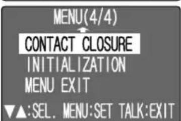
Press [SELECT (▼)] to display the "MENU (4/4)" screen, and then move the cursor to "CONTACT CLOSURE".
3

Press [MENU].
(The "CONTACT CLOSURE" screen will be displayed.)
4
Press [SELECT (▲/▼)] to set the output time.
- The setting can be from approx. 2 seconds to approx. 30 seconds.
5

Once the alarm output time setting has been made, press 【MENU】.
(The display will return to the "MENU (4/4)" screen.)
6
■ To continue making further settings ...
Move the cursor to the desired item, and press 【MENU】.
(Refer to step 5 on page 35.)
■ To complete the settings ...

Press 【SELECT (▼)】 to return to the "MENU (4/4)" screen, and then move the cursor to "MENU EXIT" and press 【MENU】.
Restoring settings to defaults
This returns all menu settings to their default settings.
![[SELECT (▲) ] [SELECT (▼) ] [MENU] Panasonic V1-0301 i→i1 MONITOR TALK CALL DOOR](/content/2026/05/1074749/images/b1cdb71000c945b439a120347e176870660150c92e3e2b9f84ecb2cb3a7b9d67.jpg)
1

Cursor
Press [MENU].
(The "MENU (1/4)" screen will be displayed.)
2

Press 【SELECT (▼)】 to display the "MENU (4/4)" screen, and then move the cursor to "INITIALIZATION".
3

Press 【MENU】.
(The "INITIALIZATION" screen will be displayed.)
4
Press 【SELECT (▼)】 to move the cursor to "YES" or "NO".
5
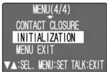
Press [MENU].
(The display will return to the "MENU (4/4)" screen.)
- If set to "YES"
– All settings will be returned to their default settings.
- If set to "NO"
– The settings will remain unchanged.
6
■ To continue making further settings ...
Move the cursor to the desired item, and press 【MENU】.
(Refer to step 5 on page 35.)
■To complete the settings ...

Press 【SELECT (▼)】 to return to the "MENU (4/4)" screen, and then move the cursor to "MENU EXIT" and press 【MENU】.
Troubleshooting
| Problem | Cause and solution |
| The display is not clear or is blurry. | ·The surface of the door station is dirty. Clean it with a soft dry cloth. ·The surface of the door station is wet with dew. Wait for the condensation to evaporate. ·Change the brightness of the display by pressing [BRIGHT]. |
| The display is white, or black or white lines are shown on the display. | ·Strong light such as sunlight is shining into the camera of the door station. Though this may cause the display image to become difficult to see, it is not a malfunction. |
| The color of the display is different from the actual color. | ·Certain types of lighting (dusk, incandescent lighting, etc.) may be shining into the camera. We recommend lighting the area of the door station with white, fluorescent light. |
| The display will not display anything or no voices can be heard. | ·The power cord is not connected. Check the connections. ·Contact our service personnel. |
| The monitor station and sub monitor station does not ring. | ·Is “RINGER VOLUME” set to “OFF” in the menu settings? ·The power cord is not connected. Check the connections. ·Contact our service personnel. |
| I cannot talk to the visitor or the ringer tone rings regularly. | ·Press and hold [BRIGHT] for about 10 seconds until a beep sounds to initialize the system. Wait for another 10 seconds and try again. ·Contact our service personnel. |
| Sound cuts in/out or fades. | ·The surroundings of the monitor station or the door station are noisy. If you are using [PUSH] mode, your conversation may be interrupted. Try [HOLD] mode. |
| Your voice cannot be heard by the outside visitor. | ·Is the unit in [HOLD] mode? (Page 26) Is “PT” displayed in the LCD screen? |
| The outside visitor complains the door station does not beep when the call button is pressed. | ·Due to the PBX system, the beep may not sound if “PBX SELECT” is “ON”. |
| The display turns off during a conversation (Sound continues). | ·You talked for more than about 3 minutes in [HOLD] mode. The maximum display time is approximately 3 minutes. |
Cleaning
Clean the unit with a soft, dry cloth when cleaning. For excessive dirt, wipe the unit with a slightly damp cloth.

Important information:
- Do not use anything containing alcohol, polish powder, powder soap, benzine, thinner, wax, petroleum, or boiling water. Also do not spray with insecticide, glass cleaner, or hair spray. This could cause a change in color or quality.
Technical data about this product
Monitor station
Power supply: 24 V DC
Current consumption: Standby: Approximately 44 mA
At operation: Approximately 450 mA
Video Output Level: 1 Vp-p, 75 Ω (NTSC color signal)
Dimensions: Approximately height 145 mm x width 165 mm x depth 44 mm (5 3/4" x 6 1/2" x 1 3/4")
Mass (Weight): Approximately 600 g (1.32 lb.)
Operating environment: 0 °C to 40 °C (32 °F to 104 °F), Up to 90 % RH
(Relative Humidity) non condensing
Installation method: Exposure mount
Flush mount (Optional Flush mount unit is required.)
External material: Flame retardant ABS resin (panel: acrylic resin)
Note:
- To connect to a door opener and chime, make sure the door opener and chime is:
– Normal open (Low active)
– Less than 30 V AC (1 A), 24 V DC (1 A)
- About the chime:
When a door station call is answered, the Normal open output turns OFF. If it is not answered, the Normal open output turns ON for the time (2 - 30 seconds) set in the menu. (For details, please see the operating instructions of the connected device.)
AC adaptor (Part number: PFAP1014)
Power supply: 100 V – 240 V AC, 50 Hz / 60 Hz
Output voltage: 24 V DC
Output current: 2 A
Dimensions: Approximately height 120 mm x width 60 mm x depth 35 mm
(4 3/4" x 2 3/8" x 1 3/8")
Mass (Weight): Approximately 310 g (0.68 lb.)
Operating environment: 0 °C to 40 °C (32 °F to 104 °F), Up to 90 % RH
(Relative Humidity) non condensing
Note:
- Design and specifications are subject to change without notice.
- The pictures and illustrations in these instructions may vary slightly from the actual product.
For your future reference
Date of purchase
Serial number (found on the rear of the unit)
Dealer's name and address
Dealer's telephone number
Attach your sales receipt here.
Panasonic Consumer Electronics Company,
Division of Panasonic Corporation of North America
One Panasonic Way, Secaucus, New Jersey 07094, U.S.A.
Panasonic Puerto Rico, Inc.
San Gabriel Industrial Park, Ave. 65 de Infantería, Km. 9.5, Carolina, Puerto Rico 00985, U.S.A.
Copyright:
This material is copyrighted by Panasonic Communications Co., Ltd., and may be reproduced for internal use only. All other reproduction, in whole or in part, is prohibited without the written consent of Panasonic Communications Co., Ltd.
© 2005 Panasonic Communications Co., Ltd. All Rights Reserved.
- INSTALLATION AND OPERATION GUIDE
- IMPORTANT INFORMATION
- INTRODUCTION AND INSTALLATION
- USING THE UNIT
- MENU SETUP
- HELP
- GENERAL INFORMATION
- CAUTION
- IMPORTANT SAFETY INSTRUCTIONS
- ADDITIONAL SAFETY INFORMATION
- NOTE
- FOR BEST PERFORMANCE
- FCC AND OTHER INFORMATION
- INCLUDED ITEMS
- MONITOR STATION
- OPTIONAL ITEM INFORMATION
- AVAILABLE OPTIONAL ITEMS
- COMPATIBLE PBXS
- LOCATION OF CONTROLS
- BEFORE INSTALLATION
- STANDARD INSTALLATION POSITION OF THE MONITOR STATION
- PRECAUTIONS WHEN CONNECTING
- POWER CABLE/WIRE TYPE AND DISTANCE
- INSTALLING THE MONITOR STATION
- REMOVE THE FRONT CASE FROM THE BOTTOM CASE
- TO ATTACH THE AC ADAPTOR AND THE DC TERMINAL TO A WALL
- TO ATTACH THE POWER CABLE
- TO ATTACH THE WIRES
- CONNECTING TO A PBX
- IMPORTANT
- BEFORE USING THE UNIT
- ON-SCREEN DISPLAYS
- BRIGHTNESS SETTING / TALK VOLUME SETTING
- BRIGHTNESS SETTING
- ANSWERING A DOOR CALL USING THE MONITOR STATION
- AVAILABLE ANSWER MODES
- 【PUSH】 MODE (PUSH TO TALK MODE)
- 【HOLD】 MODE (PRESS TO TALK MODE)
- MONITORING THE OUTSIDE (THE PROCEDURE IS THE SAME FOR A SUB MONITOR STATION.)
- PRESS [MONITOR]
- TO END MONITORING, PRESS 【MONITOR】
- WHEN CONNECTING EXPANSION UNITS
- IF THE FOLLOWING HAPPENS
- USING BY GROUPS
- SETTINGS BEFORE USE
- ● MONITOR STATION AND SUB MONITOR STATION SETTINGS (DEFAULT SETTINGS ARE ALL “GROUP A”.)
- ● CAMERA SETTINGS (DEFAULT SETTINGS ARE ALL "ON".)
- WHEN CALLING THE MONITOR STATION AND SUB MONITOR STATION
- CALLING TONE
- CALLING FROM A DOOR STATION
- OPENING A DOOR (DOOR OPENER)
- MONITOR STATION/SUB MONITOR STATION SCREEN CONFIGURATION
- SUB MONITOR STATION MENU SCREEN
- DISPLAY THE MENU SCREEN AND THEN MAKE THE SETTINGS
- MOVING THE CURSOR
- MAKE THE SETTING
- SETTING THE RECEIVE VOLUME (DEFAULT SETTING IS "MID".)
- SETTING THE RINGER VOLUME (DEFAULT SETTING IS "HIGH".)
- SELECTING THE RINGER
- SELECTING THE PBX (DEFAULT SETTING IS "ON".)
- SETTING MONITOR STATION OR SUB MONITOR STATION INTO GROUPS (DEFAULT SETTING IS "GROUP A".)
- SELECTING A CAMERA (DEFAULT SETTING IS FOR ALL CAMERAS TO BE "ON".)
- SETTING THE ALARM OUTPUT TIME (DEFAULT SETTING IS "10SEC.")
- RESTORING SETTINGS TO DEFAULTS
- CLEANING
- TECHNICAL DATA ABOUT THIS PRODUCT
- AC ADAPTOR (PART NUMBER: PFAP1014)
- FOR YOUR FUTURE REFERENCE
- ATTACH YOUR SALES RECEIPT HERE
- PANASONIC PUERTO RICO, INC
- COPYRIGHT
Brand : PANASONIC
Model : VL-GM301A
Category : Intercom