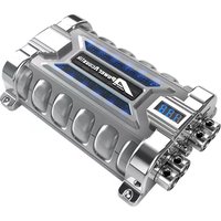
PCX-10F - Electric capacitor Power Acoustik - Free user manual and instructions
Find the device manual for free PCX-10F Power Acoustik in PDF.


| Brand | Power Acoustik |
| Model | PCX-10F |
| Type | Passive 10-inch Subwoofer |
| Impedance | Single 4 Ohm (SVC) |
| Sensitivity | 87 dB (2.83V/1m) |
| RMS Power Handling | 250 Watts |
| Peak Power Handling | 500 Watts |
| Frequency Response | 25 Hz - 500 Hz |
| Mounting Depth | 5.5 inches (139.7 mm) |
| Mounting Hole Diameter | 9.2 inches (233.68 mm) |
| Overall Diameter | 10.5 inches (266.7 mm) |
| Weight | 8.5 lbs (3.86 kg) |
| Magnet Size | 30 oz (850 g) |
| Cone Material | Injected Polypropylene |
| Surround Material | Butyl Rubber |
| Voice Coil Diameter | 2-inch (50.8 mm) |
| Terminal Type | Push-Button Spring-Loaded |
| Recommended Enclosure Type | Sealed or Ported (0.8-1.5 cu.ft.) |
| Recommended Amplifier Power | 200-300 Watts RMS |
| Warranty | 1 Year Limited Manufacturer |
Frequently Asked Questions - PCX-10F Power Acoustik
User questions about PCX-10F Power Acoustik
0 question about this device. Answer the ones you know or ask your own.
Ask a new question about this device
Download the instructions for your Electric capacitor in PDF format for free! Find your manual PCX-10F - Power Acoustik and take your electronic device back in hand. On this page are published all the documents necessary for the use of your device. PCX-10F by Power Acoustik.
USER MANUAL PCX-10F Power Acoustik
Surge Voltage.... 20 DCV
E. S. R. (Equivalent Series Resistance)..... 0.0015 ohm @ 120Hz / 25°C
Capacitance Tolerance....± 10 %
MODEL NO.: PCX-20F
20 Farad Hybrid Super Capacitor with 3-Digit Blue Voltage Meter
Capacitance.... 20,000.000 micro farad (20 Farad)
Working Voltage.... 16 DCV
Surge Voltage.... 20 DCV
E. S. R. (Equivalent Series Resistance)..... 0.0015 ohm @ 120Hz / 25°C
Capacitance Tolerance....± 10 %
MODEL NO.: PCX-30F
30 Farad Hybrid Super Capacitor with 3-Digit Blue Voltage Meter
Capacitance.... 30,000.000 micro farad (30 Farad)
Working Voltage.... 16 DCV
Surge Voltage.... 20 DCV
E. S. R. (Equivalent Series Resistance)..... 0.0015 ohm @ 120Hz / 25°C
Capacitance Tolerance....± 10 %
DETAILED FEATURES:
a) 3 digit super bright blue voltage meter measures 0.1V DVC range.
b) Blue LED lighting window illuminates, and goes to sleep status when the amplifier is switched off and there's no voltage variation within 3 minutes.
c) Reverse polarity connection warning buzzer. If the capacitor is connected incorrectly by reversing the positive and negative wires during the installation process, the buzzer on the PCB will ring till you correct polarity connection.
d) Over voltage limit and low battery voltage limit warning. When the system voltage goes ABOVE 17 DCV or BELOW 10 DCV, the buzzer will issue warning sound.

INSTALLATION AND MOUNTING:
Securely mount the capacitor using supplied hardware. Be careful when choosing mounting location to avoid moving parts and possible exposure to moisture.

CHARGING THE CAPACITOR AND WIRING:
The capacitor must be charged before connecting the Power and Ground cables to the capacitor. Failure to charge the capacitor will result in a large spark generated from the rapid inflow of current.
CHARGING
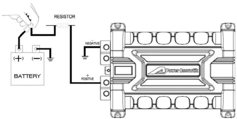
- To charge the capacitor:
Make capacitor positive terminal connections with amplifier and tighten the bolt. Do not over-tighten the bolt!
Caution: Stripped terminals are not covered under the capacitor's warranty.
- Connect the ground cables of the battery, amplifier, and capacitor separately to chassis.
- Place the supplied charging resistor between the positive terminal of the capacitor and the battery's positive terminal. After 5\~60 seconds, the capacitor will be fully charged.
Caution: The resistor will become hot!
- Immediately after the charging process, take away the charging bulb from the connecting wire, and connect the positive cable to the positive terminal on the capacitor.
CAPACITOR WIRING DIAGRAM:

flowchart
graph TD
    A["Amplifier (-)"] -->|REMOTE| B["Power Distribution Block"]
    C["Amplifier (+)"] -->|REMOTE| B
    B --> D["Head Unit"]
    D --> E["POWER Distribution Block"]
    E --> F["Power Reusitin"]
    G["FUSE BLOCK"] --> H["BATTERY"]
    I["NEGATIVE"] --> J["Power Distribution Block"]
    K["POSITIVE"] --> L["Battery"]
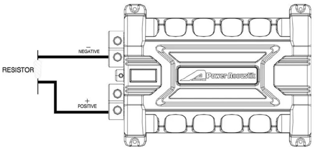
DISCHARGING THE CAPACITOR:
Never remove the capacitor without discharging the stored power – it can give a dangerous electrical shock!
To disconnect the capacitor, follow these instructions:
- Disconnect the cables from the capacitor in the following order:
a) positive (+) cable
b) ground (-) cable - Holding the resistor provided, touch the leads to the positive (+) and ground (-) terminals of the capacitor. After 1\~5 minutes, the capacitor will be discharged (The
charging resistor will become hot ! ) Then you can safely remove and handle it.
DISCHARGING
WARNING!!
THIS POWER CAPACITOR MAY EXPLODE AND CAUSE SERIOUS INJURY IF ABUSED OR CONNECTED IMPROPERLY. PLEASE REFER TO THE INSTRUCTIONS CONTAINED IN THIS MANUAL FOR CORRECT OUNTING, CHARGING/DISCHARGING AND WIRING CONNECTION FOR THIS CAPAPCITOR PRIOR TO INSTALLATION.


Brand : Power Acoustik
Model : PCX-10F
Category : Electric capacitor