M1000 - Blender OMEGA - Free user manual and instructions
Find the device manual for free M1000 OMEGA in PDF.


| Product Type | Blender |
| Brand | Omega |
| Model | M1000 |
| Motor Power | 1000 W |
| Voltage | 120 V / 60 Hz |
| Capacity | 1.5 L |
| Jar Material | Tritan copolyester (BPA-free) |
| Blade Material | Stainless steel |
| Speed Settings | Variable speed with pulse function |
| Dimensions (H x W x D) | 40 cm x 20 cm x 20 cm |
| Weight | 5 kg |
| Main Functions | Blending, pureeing, crushing ice, making smoothies |
| Cleaning & Maintenance | Removable parts are dishwasher safe; wipe motor base with damp cloth |
| Safety Features | Overload protection, non-slip feet, safety lock lid |
| Spare Parts & Repairability | Replacement jar, lid, blade assembly available; user-replaceable parts |
| Warranty | 15-year warranty on motor |
Frequently Asked Questions - M1000 OMEGA
User questions about M1000 OMEGA
0 question about this device. Answer the ones you know or ask your own.
Ask a new question about this device
Download the instructions for your Blender in PDF format for free! Find your manual M1000 - OMEGA and take your electronic device back in hand. On this page are published all the documents necessary for the use of your device. M1000 by OMEGA.
USER MANUAL M1000 OMEGA
Eat well, drink well and live well with Omega www.omegajuicers.com
Drink Mixers
M1000/M3000 SERIES
Product Contents

natural_image
Two black Omega brand water purifiers with metal handles and control knobs, shown from different angles (no text or symbols visible on the devices themselves)Omega®
CONTENTS
Important Safeguards ____ 2
Specifications 3
Parts and Features 4
Operating & Cleaning Procedures 5-8
Wall Mounting 9-10
M1000/M1220 Exploded View 11
M1000/M1220 Parts List 12
M3000/M3220 Exploded View 13
M3000/M3220 Parts List 14
IMPORTANT SAFEGUARDS
We have provided many important safety messages in this manual and on your appliance. Always read and obey all safety messages.
WARNING – When using electrical appliances, basic safety precautions should be followed to reduce the risk of personal injury, including the following:
- Read all instructions before using mixer.
- Plug into a grounded 3 prong outlet.
- Do not remove ground plug.
- Do not use an adapter.
- Do not use an extension cord.
- Disconnect power before cleaning or servicing, and before installing or removing agitator.
-
Do not spray or submerge mixer.
• Always use metal container when mixing. -
Do not put spoon or other utensils in metal container when mixing.
- Do not allow agitator to hit container sides when mixing.
- Inspect mixer and agitator daily.
- Replace agitators every 90 days.
- Do not operate any appliance with a damaged cord or plug, or after the appliance malfunctions or is damaged in any manner.
SAVE THESE INSTRUCTIONS
SPECIFICATIONS
M1000
Rated voltage: AC 120V 50/60HZ
Rated power: 162W
Cord length: 5 foot
Gross weight: 16.53 lb
Box size: 9.06"x9.06"x22.05"
M1220
Rated voltage: AC 220V 50/60HZ
Rated power: 162W
Cord length: 5 foot
Gross weight: 16.53 lb
Box size: 9.06"x9.06"x22.05"
M3000
Rated voltage: AC 120V 50/60HZ
Rated power: 485W
Cord length: 5 foot
Gross weight: 36.6 lb
Box size: 13.5"x11.2"x23.8"
M3220
Rated voltage: AC 220V 50/60HZ
Rated power: 485W
Cord length: 5 foot
Gross weight: 36.6 lb
Box size: 13.5"x11.2"x23.8"
PARTS AND FEATURES
The parts and features of your mixer are shown on this page.
Become familiar with all the parts and features before using the mixer.
M3000/ M3220
M1000/ M1220
TOP VIEW OF CONTROLS TOP VIEW OF CONTROLS

Operating procedure
Connection to main power supply.
- The electrical safety of this drink mixing machine can only be achieved if the machine is properly connected to an appropriate grounded receptacle that is in compliance with current national safety standards. Therefore, the manufacturer cannot be held responsible for damage and/or injury caused by failure to connect the unit to an appropriate power source.
- For a safe and correct installation, connect the unit to a dedicated outlet.
- Do not alter the cord or plug in any way.
- The entire length of the power supply cord must not, in any way, be compressed (bent or bunched together) nor may extension cords be used.
WARNING: THIS UNIT MUST BE PROPERLY ELECTRICALLY GROUNDED TO AVOID POSSIBLE FATAL ELECTRICAL SHOCK OR SERIOUS INJURY TO THE OPERATOR. THE POWER CORD IS PROVIDED WITH A THREE PRONG GROUNDED PLUG. IF A THREE-HOLE GROUNDED ELECTRICAL OUTLET IS NOT AVAILABLE, USE AN APPROVED METHOD TO GROUND THE UNIT. DO NOT USE EXTENSION CORDS WITH THIS UNIT. DO NOT "GANG" TOGETHER WITH OTHER ELECTRICAL DEVICES ON THE SAME OUTLET.

natural_image
Diagram showing four types of electrical plugs connected in a row: straight, two socket, one plug with internal circuit, and one plug with terminal (no text or symbols)FIGURE A FIGURE B
OPERATING AND CLEANING PROCEDURE
Mixing a drink
- Plug the drink mixer into a grounded outlet.
- Place the ingredients into the container supplied. The basic milkshake recipe is:
3 No. 24 scoops of ice cream.
4 ounces of very cold milk.
1-1/2 ounces of syrup.
M1000
- Select the required speed using the 2-speed selector switch.
- Position the container in the container guide and move the container upwards to activate the mixer. Set the container down onto the upper level of the container rest.
- When the drink is completely mixed, lift the container up off the container rest and pull down from the container guide. The mixer will now turn off. The container can now be removed or left in the lower container guide position.
- Please note that the mixer will not operate without the container being in the upper position on the container rest.
M3000
- Select the desired speed using the 3-speed selector switch. Switch the toggle switch to the ON position.
- Position the container in the container guide and move the container upwards to activate the mixer. Set the container down onto the upper part of the container rest. If the pulse operation is required, use the toggle switch to perform this function.
- When the drink is completely mixed, lift the container up off the container rest and pull down from the container guide. The unit will now turn off. The container can now be removed or left in the lower container guide position.
- Please note that the mixer will not operate without the container being in the upper position on the container rest.
OPERATING AND CLEANING PROCEDURE
NOTE: Inspect agitator(s) daily and replace every 90 days.
WARNING
Cut Hazard

Always use the metal container when mixing.
Do not put spoon or other utensils in metal container when mixing.
Failure to follow these instructions can result in cuts.
Using the container rest
- To turn the unit off, rest the container on the lower or standby container rest position.
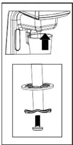
Replacing the agitator
The drink mixer ships with a solid agitator installed on each shaft.
- Unplug the mixer.
- If the shaft is to be removed, normally a quick turn counter clockwise will loosen the shaft. If not, remove the top cover and use a flat head screwdriver inserted into the top of the motor shaft to prevent the motor from turning.
- To remove the agitator, loosen the bolt by turning it counter clockwise with a 5/16" wrench.
- To install the new agitator, turn the bolt into the shaft and tighten.
To prevent damage to the agitator, do not use pliers to grip the agitator blades while tightening or loosening.
natural_image
Technical line drawing of a kitchen appliance with a bucket and handle, shown from top and side views (no text or symbols)OPERATING AND CLEANING PROCEDURE
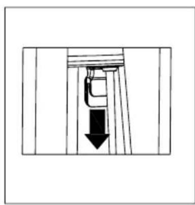
Removing/installing the container guide pin & housing plug
- Unplug the drink mixer.
- Hold the container guide by the indents on each side and pull straight down.
- Press the retainer clip and slide the guide pin out of the guide.
- Reverse the above steps to reinstall making note of the correct orientation.
natural_image
Simple line drawing of a mechanical component with a downward arrow indicating force or direction (no text or symbols)

natural_image
Technical line drawing of a mechanical assembly with internal components and an upward arrow (no text or symbols)Care and cleaning
- Place a drop of detergent and 1 cup of water into the container.
- Position the container into the container guide and mix on low speed for 5 seconds.
- Empty and refill with clean water and repeat for 5 seconds to rinse.
- Remove the container guide and wash with hot soapy water, then rinse.
- Clean the housing with a damp soapy cloth.
NOTE: Do not spray or submerge the mixer. Resulting water damage will not be covered under warranty.
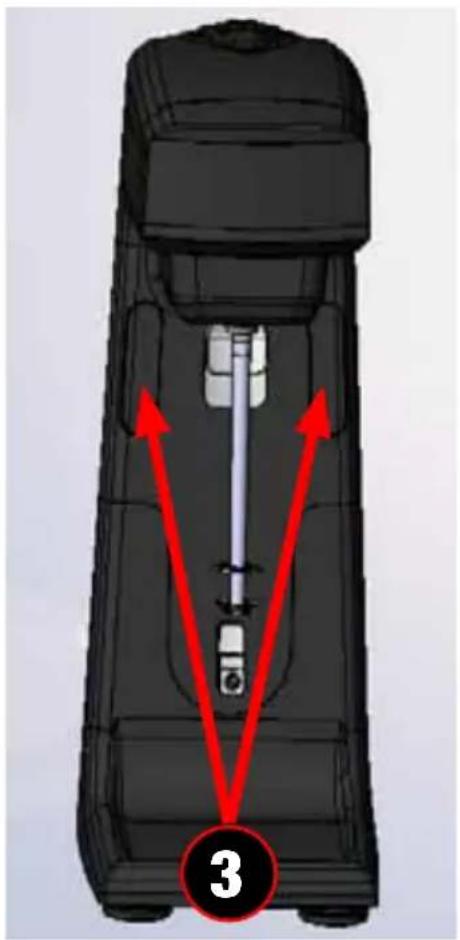
WALL MOUNTING
Step:
- Remove M4X12 screws on back of the machine.
- Separate main housing and base.
- Remove two black magnet covers.
- Fixed the main housing on the wall by using the four screws and wall anchors supplied.
- Assemble two black magnet covers.

natural_image
Back view of a black mobile phone casing with internal compartments and a red arrow pointing to the bottom portion, labeled '1' (no text or symbols on the device itself)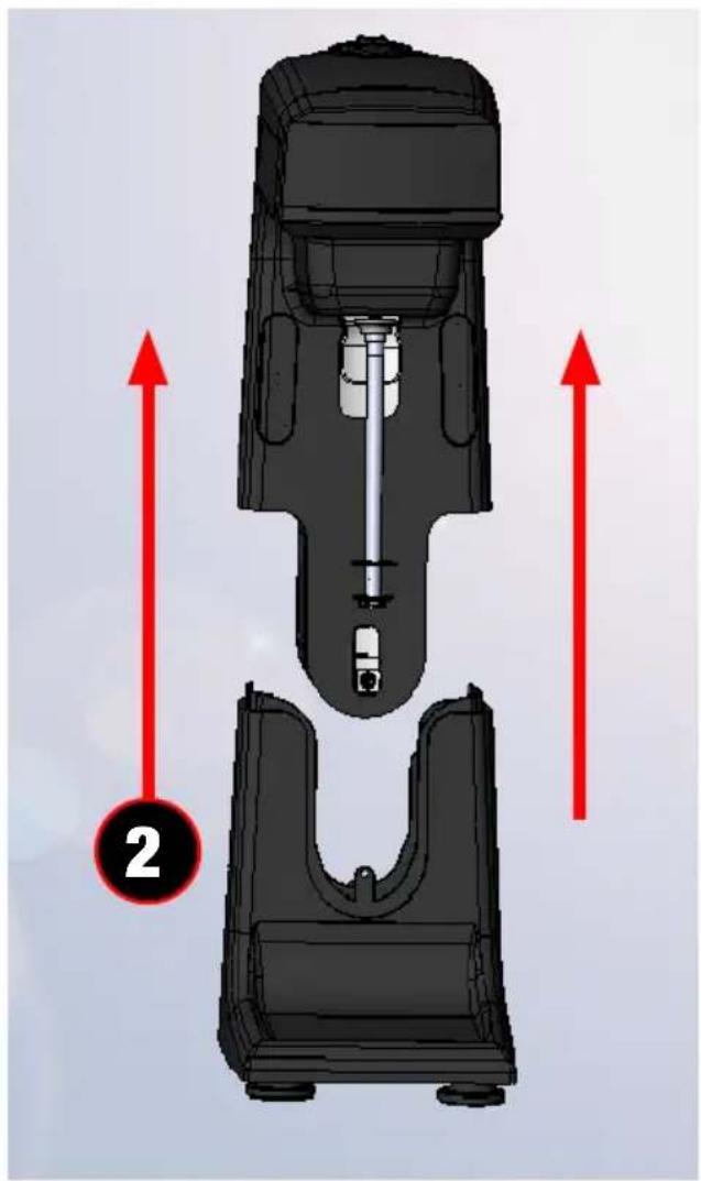
natural_image
Mechanical component diagram showing internal structure with red arrows indicating upward motion (no text or symbols)WALL MOUNTING

natural_image
Cross-sectional diagram of a mechanical device with internal components and a red directional arrow (no text or symbols)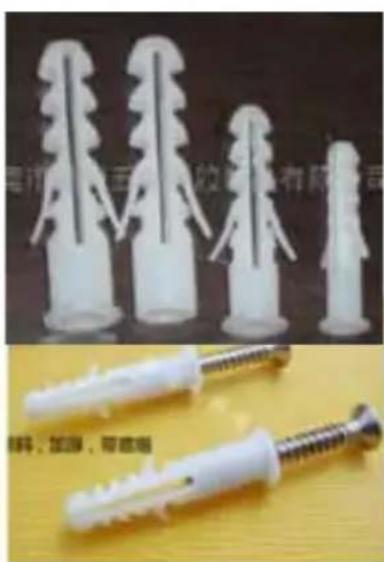
natural_image
Two types of plastic screw packages displayed: one with white plastic caps and another with metallic screws (no text or symbols visible)M1000/M1220 EXPLODED VIEW
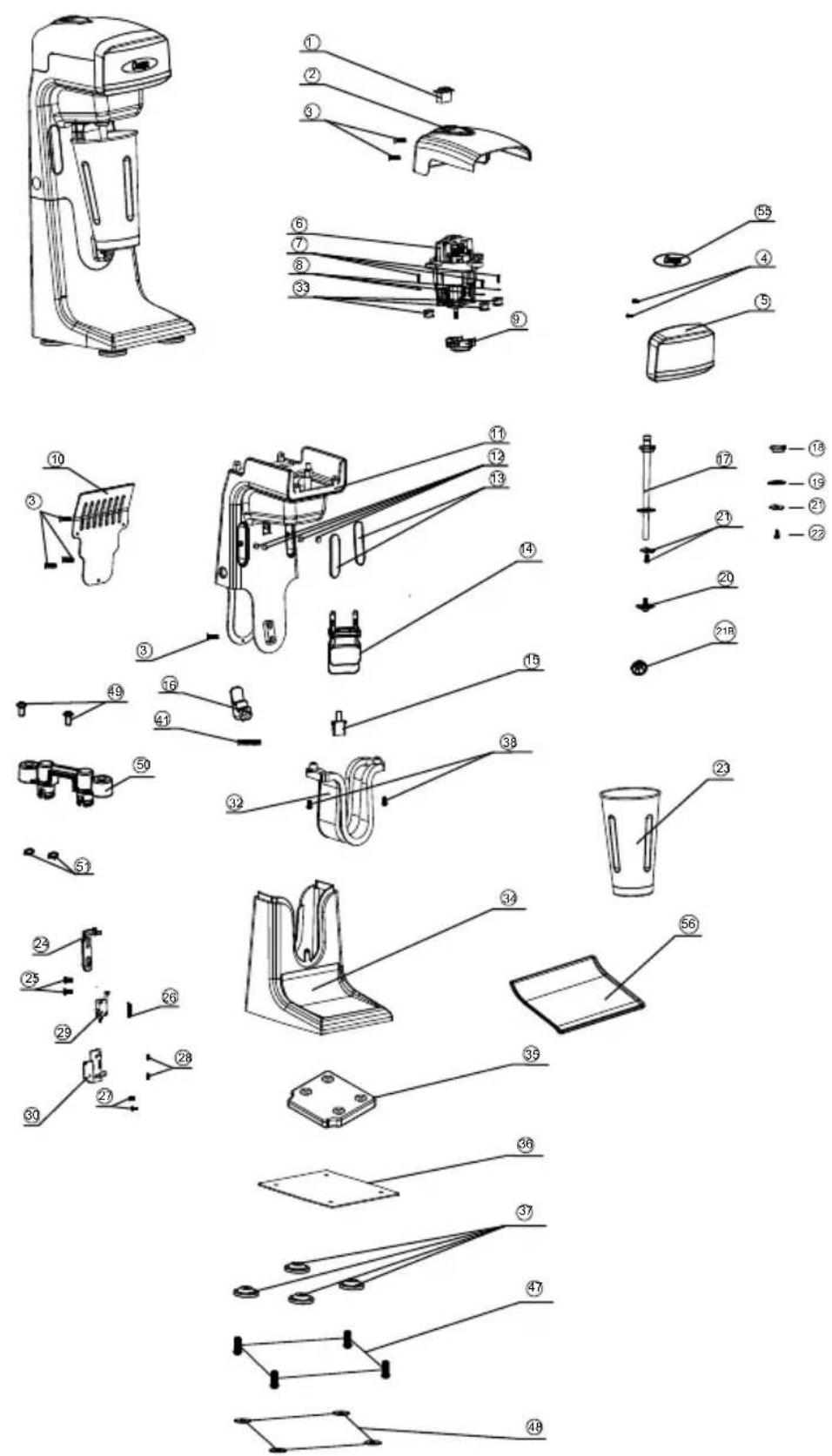
| No. | Part # | Description Qty | |
| 1 | PM1-SWITCH Power Switch 1 | ||
| 2 | PM1-2B Top Cover Black 1 | ||
| 3 | PM1-3 Screw#1 6 | ||
| 4 | PM1-4 Screw#2 2 | ||
| 5 | PM1-5C Front Cover Chrome 1 | ||
| 6 | PM1-MOTOR-120 Motor 1/2HP 120V 1 | ||
| PM1-MOTOR-240 Motor 1/2HP 240V 50/60HZ | 1 | ||
| 7 | PM1-3 Screw#1 3 | ||
| 8 | PM1-8 Spring Washer | 1 | |
| 9 | PM1-9 Lower motor pad | 1 | |
| 10 | PM1-10B | Back Panel black | 1 |
| 11 | PM1-11B | Upper housing Black | 1 |
| 12 | PM1-12 | Magnet | 4 |
| 13 | PM1-13B | Magnet cover black | 2 |
| 14 | PM1-14 | Upper cup holder | 1 |
| 15 | PM1-15 | Microswitch activator | 1 |
| 16 | PM1-16 | Lower cup holder | 1 |
| 17 | PM1-SHAFT | Stir Shaft with parts 18,19,22 | 1 |
| 20 | PM1-20 | Agitator standard with locking bolt 1 | |
| 21 | PM1-21 | Agitator hinged | 1 |
| 21B | PM1-21B | Agitator high power | 1 |
| 22 | PM1-22 | Screw#3 1 | |
| 23 | PM1-CUP | Cup | 1 |
| PM1-CUP-O | Cup with lazer engraved Omega | 1 | |
| 24 | PM1-24 | Switch ejector | 1 |
| 25 | PM1-25 | Screw#4 4 | |
| 26 | PM1-26 | Spring | 1 |
| 27 | PM1-27 | Screw#5 2 | |
| 28 | PM1-28 | Screw#6 2 | |
| 29 | PM1-29 | Microswitch | 1 |
| 30 | PM1-30 | Microswitch bracket | 1 |
| 32 | PM1-32 | Inside cover | 1 |
| 33 | PM1-33 | Upper motor supports | 3 |
| 34 | PM1-34B | Lower housing | 1 |
| 35 | PM1-35 | Base support | 1 |
| 36 | PM1-36 | Bottom cover | 1 |
| 37 | PM1-37 | Feet | 4 |
| 38 | PM1-38 | Screw#7 2 | |
| 41 | PM1-41 | Screw#8 1 | |
| 47 | PM1-47 | Screw#9 4 | |
| 48 | PM1-48 | Washer | 4 |
| 49 | PM1-25 | Screw#4 5 | |
| 50 | PM1-50 | Upper cup holder retainer | 1 |
| 51 | PM1-51 | Retainer spring | 2 |
| 56 | PM1-56 | Drip tray | 1 |
One (1) year Parts and Labor
M3000/M3220 EXPLODED VIEW

| No. Part # Description Qty | |||
| 1 PM3 | -SWITCHT Toggle switch 3 | ||
| 2 PM3 | -2 Screw#10 2 | ||
| 3 PM3 | -3 Screw#11 1 | ||
| 4 PM3 | -4C Top cover 1 | ||
| 5 PM3 | -SWITCHR Rocker switch 3 | ||
| 6 PM3 | -6 Upper motor support 1 | ||
| 7 PM3 | -MOTOR-120 Motor 1/2HP 120V 3 | ||
| PM3-MOTOR-240 Motor 1/2HP 240V 50/60HZ 3 | |||
| 8 PM3 | -8 Spring Washer 4 | ||
| 9 PM1 | -9 Lower motor support 3 | ||
| 16 | PM1-16 | Lower cup holder | 3 |
| 17 | PM1-SHAFT | Stir Shaft with parts 18,19,22 | 3 |
| 20 | PM1-20 | Agitator standard with locking bolt | 3 |
| 21 | PM1-21 | Agitator hinged | 3 |
| 21B | PM1-21B | Agitator high power | 3 |
| 22 | PM1-22 | Screw#3 | 3 |
| 23 | PM1-CUP | Cup s/steel | 3 |
| 0 PM1 | -CUP-O Cup s/steel with lazer engraved Omega 3 | ||
| 25 | PM1-25 | Screw#4 | 4 |
| 26 | PM1-26 | Spring | 1 |
| 27 | PM1-27 | Screw#5 | 2 |
| 28 | PM1-28 | Screw#6 | 3 |
| 29 | PM1-29 | Microswitch | 3 |
| 30 | PM1-30 | Microswitch bracket | 1 |
| 37 | PM3-37 | Washer | 4 |
| 38 | PM3-38C | Front cover | 1 |
| 40 | PM3-40B | Housing complete | 1 |
| 41 | PM1-41 | Screw#8 | 3 |
| 42 | PM3-42 | Foot rear | 2 |
| 43 | PM3-43 | Front suction cup | 2 |
| 44 | PM3-44 | Foot Front 2 | |
| 45 | PM3-45 | Screw#12 1 | |
| 46 | PM3-46 | Drip tray | 1 |
| 47 | PM3-3 Screw#11 4 | ||
| 49 | PM1-25 | Screw#4 | 5 |
| 50 | PM1-50 | Upper cup holder retainer | 1 |
| 51 | PM1-51 | Retainer Spring | 1 |
| 52 | PM3-52 | Power cord cover | 1 |
| 53 | PM3-53B | Back cover | 1 |
| 54 | PM1-22 | Screw#3 | 3 |
| 57 | PM1-25 | Screw#4 | 9 |
| 58 | PM3-58 | Upper cup holder | 3 |
| 59 | PM3-59 | Microswitch activator | 3 |
| 60 | PM1-24 | Switch ejector 3 | |
One (1) year Parts and Labor
Omega
Omega PrOducts, Inc.
6291 Lyster Lane
Harrlsburg, Pa 17111-4523 u.s.a.
PHOne: 1.800.633.3401
Fax: 717.561.1298


- Drink Mixers
- M1000/M3000 SERIES
- Omega®
- CONTENTS
- IMPORTANT SAFEGUARDS
- SAVE THESE INSTRUCTIONS
- SPECIFICATIONS
- M1000
- M1220
- M3000
- M3220
- PARTS AND FEATURES
- Operating procedure
- OPERATING AND CLEANING PROCEDURE
- Mixing a drink
- WARNING
- Cut Hazard
- Using the container rest
- Replacing the agitator
- Removing/installing the container guide pin & housing plug
- Care and cleaning
- WALL MOUNTING
- Step:
- M1000/M1220 EXPLODED VIEW
- M3000/M3220 EXPLODED VIEW
- Omega
Brand : OMEGA
Model : M1000
Category : Blender