
84131 - Barbecue HAMILTON BEACH - Free user manual and instructions
Find the device manual for free 84131 HAMILTON BEACH in PDF.


| Product Type | Outdoor Gas Grill |
| Model | 84131 |
| Brand | Hamilton Beach |
| Fuel Type | LP (Liquefied Petroleum Gas) |
| Number of Main Burners | 3 |
| Total BTU Output | 33,000 Btu/h (11,000 Btu/h per burner) |
| Ignition | Electronic with match lighting backup |
| Temperature Gauge | Built-in |
| Cooking Grate Material | Cast iron |
| Heat Diffusers | Stainless steel flame tamers |
| Warming Rack | Yes |
| Side Shelves | Yes (left and right) |
| Cart | With casters and feet |
| LP Tank Requirement | 12" diameter x 18" tall, 20 lb max capacity, with QCC1 type I connection and OPD |
| Regulator | Provided, preset for 11" water column |
| Clearance from Combustibles | At least 36" (91 cm) sides and back |
| Intended Use | Outdoor only |
| Warranty (Burners) | 5 years |
| Warranty (Other Parts) | 1 year |
| Country of Certification | USA and Canada |
| Assembly Required | Yes |
| Included Grease Cup | Yes |
| Match Holder | Yes, hanging under side shelf |
Frequently Asked Questions - 84131 HAMILTON BEACH
User questions about 84131 HAMILTON BEACH
0 question about this device. Answer the ones you know or ask your own.
Ask a new question about this device
Download the instructions for your Barbecue in PDF format for free! Find your manual 84131 - HAMILTON BEACH and take your electronic device back in hand. On this page are published all the documents necessary for the use of your device. 84131 by HAMILTON BEACH.
USER MANUAL 84131 HAMILTON BEACH
STOP! TO PREVENT DAMAGING YOUR GRILL, READ THIS MANUAL FIRST FOR IMPORTANT UNPACKING AND ASSEMBLY INSTRUCTIONS!

Hamilton Beach®

natural_image
Hamilton Beach electric grill with three control knobs and a black body (no visible text or symbols on the device itself)
Type OG01 Gas Grill
Assembly and Operation Manual
Consumer Affairs: 1-800-851-8900
FOR OUTDOOR USE ONLY
Hamilton Beach Brands, Inc.
Glen Allen, Virginia 23060
TABLE OF CONTENTS
BEFORE YOU BEGIN
Message to Our Users .... 3
Safety Symbols 3
Installation/Safety Precautions 4
Propane and Gas Warning 4
Grill Parts List 5
Grill Parts Diagram 7
ASSEMBLY
Before the Assembly 8
Assembly Steps 11
POST-ASSEMBLY
Gas Connection 19
Leak Testing 23
Final Installation Checklist 24
Grill Lighting Instruction 24
Operating Instruction 26
Safety Tips 28
Care and Maintenance 28
Troubleshooting 30
Food Safety 31
Grill Storage 31
!DANGER
- If you smell gas:
- Shut off gas to the grill.
- Extinguish any open flames immediately.
- Open the grill lid.
- If the odor persists, keep away from the grill and call your gas supplier or your fire department immediately.
WARNING
- Do not store or use gasoline or other flammable items in the vicinity of this grill or any other appliance.
- Any LP cylinder that is not connected for use should not be stored in the vicinity of this grill or any other appliance.
BEFORE YOU BEGIN
MESSAGE TO OUR USERS
Thank you for your purchase of our Gas Grill. We sincerely wish you will enjoy using our fine products.
- Please read this user's manual in its entirety before using the grill.
- Please contact Consumer Affairs if you have any questions.
- Please read this user's manual carefully. Failure to follow the provided instruction can result in serious bodily injury and/or property damage.
- Some parts of this grill may have sharp edges. Please wear suitable protective gloves.
IMPORTANT: This grill is intended for outdoor use only and is not intended to be installed in or on recreational vehicles or boats.
NOTE TO INSTALLER: Leave this user's manual with the customer after delivery and/or installation.
NOTE TO CONSUMER: Leave this user's manual in a convenient place for future reference.
SAFETY SYMBOLS

The symbols listed here are being used throughout this manual. Please pay special attention to them. The meaning of each of the symbols is listed here:
!DANGER
This symbol indicates an imminently hazardous situation which will result in death or serious bodily injury if not followed properly.
WARNING
This symbol indicates serious bodily injury may result if the instructions are not followed.
CAUTION
This symbol indicates a hazardous situation which may result in minor or moderate bodily injury if the instructions are not properly followed.
BEFORE YOU BEGIN
WARNING
CALIFORNIA PROPOSITION 65
- Combustion by-products produced when using this product contain chemicals known to the State of California to cause cancer, birth defects, and other reproductive harm.
- This product contains chemicals, including lead and lead compounds, known to the State of California to cause cancer, birth defects, or other reproductive harm. Wash your hands after handling this product.
INSTALLATION/SAFETY PRECAUTIONS
WARNING
READ THIS SECTION FIRST BEFORE INSTALLING THE GRILL
- This grill is designed to use LP gas only. The regulator supplied by Hamilton Beach must be used.
- The installation of this appliance must conform with local codes or, in the absence of local codes, with either the National Fuel Gas Code, ANSI Z223.1/NFPA 54, or CAN/CSA B149.1, Natural Gas and Propane Installation Code, or CAN/CSA B149.2, Propane Storage and Handling Code.
- The LP gas supply tank is to be constructed and marked in accordance with the specifications for LP gas tanks of the U.S. Department of Transportation (DOT) or the National Standard of Canada, CAN/CSA-B339, Tanks, Spheres, and Tubes for the Transportation of Dangerous Goods.
- If an external electrical source is utilized, the outdoor cooking gas appliance, when installed, must be electrically grounded in accordance with local codes or, in the absence of local codes, with the National Electrical Code, ANSI/NFPA 70, or the Canadian Electrical Code, CSA C22.1. Keep the power cord of the motor away from the hot surfaces of the grill while in use. Remove and store the motor in a dry place when not in use.
- This grill is safety-certified for use in the United States and Canada only. Never modify to use in other places. Modification may cause serious bodily injury or property damage. Hamilton Beach is not responsible for any modifications, and all warranties will be void.
Total gas consumption (per hour) of OG01 grill with all burners on HI:
3 Main burners x 11,000 Btu/hr each: Total 33,000 Btu/h
BEFORE YOU BEGIN
GRILL PARTS LIST
| KEY | DESCRIPTION | QUANTITY | PART NUMBER |
| 1 | Lid | 1 | 990130100 |
| 2 | Temperature Gauge | 1 | 990127300 |
| 3 | Bezel, Temperature Gauge | 1 | 990127400 |
| 4 | Logo Plate | 1 | 990130500 |
| 5 | Lid Handle | 1 | 990127500 |
| 6 | Rotate Rod, Lid | 2 | 990127600 |
| 7 | Bezel, Rotate Rod | 2 | 990127700 |
| 8 | Firebox | 1 | 990129900 |
| 9 | Left-Side Shelf | 1 | 990127800 |
| 10 | Warming Rack | 1 | 990127900 |
| 11 | Cooking Grate | 2 | 990128000 |
| 12 | Heat Diffuser (Flame Tamer) | 3 | 990128100 |
| 13 | Main Burner | 3 | 990128200 |
| 14 | Manifold, Main Burner | 1 | 990128300 |
| 15 | Gas Valve, Main Burner | 3 | 990128400 |
| 16 | Regulator | 1 | 990129700 |
| 17 | Control Panel | 1 | 990130200 |
| 18 | Control Knob | 3 | 990128500 |
| 19 | Rear Panel | 1 | 990139500 |
| 20 | Right-Side Shelf | 1 | 990128700 |
| 21 | Grease Cup Clip | 1 | 990135000 |
| 22 | Grease Cup | 1 | 990135100 |
| 23 | Cart Frame | 1 | 990130400 |
| 24 | Tank Hold Chain | 1 | 990128800 |
| 25 | Left Panel | 1 | 990130300 |
| 26 | Match Holder Bracket (Nylon Knot) | 1 | 990137000 |
BEFORE YOU BEGIN
GRILL PARTS LIST
| KEY | DESCRIPTION | QUANTITY | PART NUMBER |
| 27 | Match Holder | 1 | 990137100 |
| 28 | Tank Baffle | 1 | 990139600 |
| 29 | Right Panel | 1 | 990135600 |
| 30 | Front Panel | 1 | 990130000 |
| 31 | Bottom Shelf | 1 | 990129800 |
| 32 | Standard Caster | 2 | 990128900 |
| 33 | Foot | 2 | 990129000 |
BEFORE YOU BEGIN
GRILL PARTS DIAGRAMGRILL PARTS DIAGRAI

ASSEMBLY
BEFORE THE ASSEMBLY
READ AND FOLLOW THE INSTRUCTIONS BELOW TO CORRECTLY UNPACK GRILL PARTS FROM SHIPPING BOX.
STEP 1:
- Open shipping box by slicing down its edges with a box cutter. Take out all the parts out of protective styrofoam as shown in Fig. A. Remove all parts from plastic bags.

Fig. A
ASSEMBLY
BEFORE THE ASSEMBLY
STEP 2:
- Open grill lid, and take out the small boxes packed within the grill head. Remove all packing materials and remove all parts from boxes as shown in Fig. B below.

Fig. B
ASSEMBLY
BEFORE THE ASSEMBLY
PLEASE READ AND FOLLOW THESE INSTRUCTIONS CAREFULLY STEP BY STEP
Tools Required:
-
2 Phillips screwdriver (not provided)
- The following hardware is provided in the blister pack:
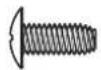

M4 x 10 Screws (16)
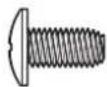

M5 x 10 Screws (5)

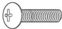
M6 x 26 Screws (2)
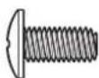

M6 x 13 Screws (20)

Flat M6 Washer (6)

M6 Compression Washer (4)
natural_image
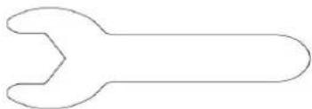
Simple line drawing of a wrench (no text or symbols)Wrench (1)

M4 Nut (4)

Match Holder Bracket (Nylon Knot) (1)

natural_image
Simple line drawing of a horizontal bar with two circular ends (no text or symbols)Match Holder (1)
ASSEMBLY
ASSEMBLY STEPS
STEP 1: Bottom Shelf
- Turn bottom shelf upside down. Attach the two (2) standard casters to right side of bottom shelf with eight (8) M6 x 13 screws as shown in Fig. 1.
- Screw one foot into the bottom shelf by hand, using the positioning gage to determine the proper depth as shown in Fig. 1. Once the foot is screwed in to the proper depth, hold it in place while tightening the nut to the bottom shelf with the provided wrench, as also shown in Fig. 1. This will secure the foot in place.
- Repeat Step 2 with the other foot.

Fig. 1
ASSEMBLY
ASSEMBLY STEPS
STEP 2: Cart
- Turn bottom shelf right side up as shown in Fig. 2.
- Attach front panel with the correct direction marked "UP" to front of bottom shelf with three (3) M5 x 10 screws as shown in Fig. 2.
- Attach left panel (marked "L") to front panel with three (3) M4 x 10 screws as shown in Fig. 2. Attach left panel to bottom shelf with one (1) M5 x 10 screw as shown in Fig. 2.
- Attach right panel (marked "R") to front panel with three (3) M4 x 10 screws. Attach right panel to bottom shelf with one (1) M5 x 10 screw as shown in Fig. 2.

natural_image
Technical line drawing of a mechanical assembly with labeled components (no text or symbols present)Fig. 2
ASSEMBLY
ASSEMBLY STEPS
STEP 3: Cart Frame
- To attach cart frame, align cart frame with side panels as shown in Fig. 3.
- Attach cart frame to left panel and right panel with six (6) M4 x 10 screws (3 on each side) as shown in Fig. 3.
- Attach cart frame to bottom shelf with two (2) M6 x 13 screws (1 on each side) as shown in Fig. 3.
- Position the ends of the tank baffle so that the holes in the ends of the baffle are aligned with the holes in the side panels, then attach the tank baffle to the left and right panel with four (4) M4 x 10 screws (2 on each side) from the outside to the inside, and four (4) M4 nuts on the inside (2 on each side), all as shown in Fig. 3.

natural_image
Technical line drawing of a mechanical device with internal components and mounting base (no text or symbols)Fig. 3
ASSEMBLY
ASSEMBLY STEPS
STEP 4: Grill Head to Cart
- Remove the tie wraps securing regulator hose to underside of grill head.
- Carefully lower the grill head onto the cart. Make sure the regulator hose is hanging outside the cart. Attach head to cart with two (2) M6 x 13 screws and two (2) M6 flat washer in the front; two (2) M6 x 26 screws in the back as shown in Fig. 4.
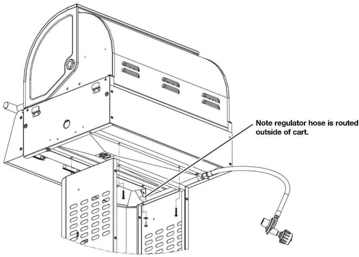
Fig. 4
ASSEMBLY
ASSEMBLY STEPS
STEP 5: Side Shelves
Attach the right shelf to firebox as follows:
- Locate side shelf onto support brackets located on side of the fire box as shown in Fig. 5a and remove the cooking grids from the firebox.
- From the outside of the firebox, attach the right shelf (marked "R") with two (2) M6 x 13 screws and two (2) M6 flat washers as shown in Fig. 5b.
- From the inside of the firebox, attach the right shelf with two (2) M6 x 13 screws and two (2) M6 compression washers as shown in Fig. 5c.
- Repeat above Steps 1–3 for the left shelf (marked "L").

Fig. 5a
ASSEMBLY
ASSEMBLY STEPS
STEP 5: Side Shelves

natural_image
Technical line drawing of a mechanical device with mounting brackets and internal components, labeled Fig. 5b (no text or symbols on the diagram itself)
natural_image
Technical line drawing of a mechanical device with internal components and an inset view labeled Fig. 5c (no text or symbols on the diagram itself)ASSEMBLY
ASSEMBLY STEPS
STEP 6: Nylon Knot
- Insert the nylon knot to the hole on the right side panel; then put the match holder in it and capture it as shown in Fig. 6.

Fig. 6
STEP 7: Grease Cup
- Place grease cup into grease cup clip and hang grease cup clip from bottom of firebox and as shown in Fig. 7.

Fig. 7
ASSEMBLY
ASSEMBLY STEPS
STEP 8: Cooking Grates
- Place heat diffusers over burners by inserting tabs into slots in front and back of the firebox as shown in Fig. 8b and Fig. 8c.
- Place cooking grates onto grate rests as shown in Fig. 8a.
- Insert warming rack at the top of the firebox as shown as shown in Fig. 8a.

POST-ASSEMBLY
GAS CONNECTION
ONLY USE THE REGULATOR AND HOSE ASSEMBLY PROVIDED WITH THIS GRILL. REPLACEMENT PRESSURE REGULATORS AND HOSE ASSEMBLIES MUST BE THOSE SUPPLIED BY THE MANUFACTURER.
This is an LP (Liquefied Petroleum Gas) configured grill. Do not attempt to use a natural gas supply unless the grill has been reconfigured for natural gas use.
The installation of this appliance must conform with local codes or, in the absence of local codes, with either the National Fuel Gas Code, ANSI Z223.1/NFPA 54, or CAN/CSA B149.1, Natural Gas and Propane Installation Code, or CAN/CSA B149.2, Propane Storage and Handling Code.
LP TANK REQUIREMENTS – THE LP TANK USED WITH YOUR GRILL MUST MEET THE FOLLOWING:
- Measurement: 12" (30.5-cm) diameter x 18" (45.7-cm) tall.
- Maximum capacity: 20 lbs. (9 kg).
- Constructed and marked in accordance with the specification for LP gas cylinders of the U.S. Department of Transportation (DOT) or the National Standard of Canada, CAN/CSA-B339, Cylinders, Spheres, and Tubes for the Transportation of Dangerous Goods. See LP tank collar for marking.
- Tank must be oriented to provide proper vapor withdrawal, as shown in Fig. 9.
- Includes a collar to protect the tank valve.
- Has no dents or rust. A dented or rusty LP tank may be hazardous and should be checked by your supplier.
- Provides a shut-off valve terminating in an LP gas tank valve outlet specified, as applicable, for connection type QCC1 in the standard for compressed gas tank valve outlet and inlet connection ANSI/CGA V-1.
- Other tanks may be acceptable for use with your grill provided they are compatible with the tank retention means in Fig. 9.
LP TANK VALVE USED MUST MEET THE FOLLOWING:
- Have type I outlet compatible with regulator provided.
- Have safety relief valve.
- UL-listed Overfill Protection Device (OPD). This OPD safety feature is identified by a unique triangular hand wheel. Only use tanks equipped with this type of valve (as the figure shown on the next page).
POST-ASSEMBLY
GAS CONNECTION
FOR YOUR SAFETY:
Ensure that the black plastic grommets of the regulator provided are in place and that the hose does not come into contact with the heat shield or the grill head.
Set the LP tank into the hole in the bottom shelf. Make sure the threaded connection at the top points toward the rear of the grill as shown in Fig. 9. Secure the tank in place with the tank hold chain as shown in Fig. 9.

natural_image
Technical line drawing of a mechanical device with a cylindrical housing and mounting base (no text or symbols)Fig. 9
POST-ASSEMBLY
GAS CONNECTION
CONNECT THE REGULATOR TO THE LP TANK - VERY IMPORTANT:
- THE REGULATOR SHALL NOT BE IN A LOCATION THAT WILL ATTAIN A TEMPERATURE ABOVE 140 °F (60°C).
- THE REGULATOR SHALL INCORPORATE A PRESSURE RELIEF VALVE OR OVERPRESSURE DEVICE.
-
THE INLET OF THE PRESSURE REGULATOR SHALL BE FITTED TO CONNECT THE TYPE I CONNECTION OF THE TANK VALVE PER ANSI Z21.81/CSA 6.25.
-
Make sure tank valve is in its full OFF position (turn clockwise to stop).
- Check tank valve to ensure it has proper external male threads (type I connection per ANSI Z21.81/CSA 6.25).
- Make sure all burner knobs are in their OFF position.
- Remove the protective cap from LP tank valve. Always use cap and strap supplied with valve.
- Inspect valve connection port and regulator assembly. Look for any damage or debris. Remove any debris. Inspect hose for damage. Never attempt to use damaged or plugged equipment. Contact your local LP gas dealer for repair.
- When connecting regulator assembly to the valve, hand-tighten nut clockwise to a positive stop as shown in Fig. 10. Do not use a wrench to tighten. Use of a wrench may damage the quick-coupling nut and result in a hazardous condition.

Fig. 10
- Open tank valve fully (counterclockwise). Use a soapy water solution to check all connections for leaks before attempting to light grill. If a leak is found, turn tank valve OFF and do not use grill until a local LP gas dealer can make repairs.
POST-ASSEMBLY
GAS CONNECTION
WARNING
- Never insert any foreign objects into the valve outlet. It may damage the valve and cause a leak. Leaking gas may result in fire, explosion, heavy body injury, or even death.
- Do not connect this grill to the self-contained LP gas system of a motor home or camper trailer.
- Do not use this grill until leak-tested.
- STOP and call the fire department if any leaks are detected.
- If you cannot stop a gas leak, close the LP tank valve IMMEDIATELY and call the LP gas supplier or the fire department.
!DANGER
Failure to follow these instructions exactly could start a fire causing death or serious injury.
- NEVER store a spare LP tank under or near grill or in an enclosed area.
- NEVER fill the tank beyond 80% full. An overfilled spare LP tank is dangerous because surplus gas may leak from the safety relief valve. The safety relief valve on an LP tank could activate to release gas and cause a fire.
- Place dust cap on cylinder valve outlet whenever the cylinder is not in use. Only install the type of dust cap on the cylinder valve outlet that is provided with the cylinder valve. Other types of caps or plugs may result in leakage of propane.
- If any gas leaks are found on the spare LP tank, IMMEDIATELY step away from the grill and call the fire department.
VERY IMPORTANT:
TO DISCONNECT LP GAS TANK:
- Turn all the knobs OFF.
- Turn the tank valve off fully (turn clockwise to stop).
- Detach the regulator assembly from tank valve by turning the quick-coupling nut counterclockwise.
- Install the protective cap back onto the LP tank valve.
LEAK TESTING
GENERAL
- Although all gas connections on the grill are leak-tested at the factory prior to shipment, a complete gas tightness check must be performed at the installation site due to possible mishandling in shipment or excessive pressure unknowingly being applied to the unit. Periodically check the whole system for leaks or immediately check if the smell of gas is detected.
BEFORE TESTING
- Make sure that all packing material is removed from the grill, including the burner tie-down straps.
- Do not smoke while leak-testing.
- Never leak-test with an open flame.
- Make a soapy solution with one part liquid detergent (or soap) and one part water. Prepare a spray bottle, brush, or rag to apply the solution to the connections. For the initial leak test, make sure the LP cylinder is full.
- Grill must be leak-tested outdoors in a well-ventilated area, away from ignition sources such as gas-fired or electrical appliances and flammable materials.
- Keep grill away from open flames and/or sparks while testing.
TO TEST
- Make sure all control knobs are in the OFF position.
- Make sure the regulator is connected tightly to the LP tank.
- Completely open LP tank valve by turning counterclockwise. If you hear a "POP" sound, turn gas off IMMEDIATELY because it indicates a heavy leak at the connection. Call your gas dealer or fire department.
- Check every connection from the LP tank up to and including the connection to the manifold pipe assembly (the pipe that goes to the burner) by brushing or spraying the soapy solution on the connections.
- If soap bubbles appear, there is a leak. Turn off LP tank valve IMMEDIATELY and retighten connections. Open LP tank valve again and recheck.
- If leaks cannot be stopped, DO NOT ATTEMPT TO REPAIR. Call Consumer Affairs for help.
- Always close the LP tank valve after leak-testing by turning clockwise. Only those parts recommended by the manufacturer should be used on the grill. Substitution will void the warranty. Do not use the grill until all connections have been checked and do not leak.
POST-ASSEMBLY
FINAL INSTALLATION CHECKLIST
- At least 36" (91-cm) clearance must be maintained from combustible constructions to the sides and back of the grill.
- There is no combustible construction material over the grill.
- All internal packaging is removed.
- Burners are sitting properly on orifices. The orifice of the valve must be located in the center of the burner section after removal and cleaning. Otherwise, it may cause serious bodily injury and property damage. Swing the burner slightly after replacing to check whether it has been installed properly.
- Knobs turn freely.
- The regulator and hose connected to the grill are provided by the manufacturer (preset for 11" [28-cm] water column).
- Unit tested and free of leaks.
- User informed of gas supply shut-off valve location.
GRILL LIGHTING INSTRUCTION
VERY IMPORTANT: ALWAYS INSPECT THE HOSE PRIOR TO EACH USE.
BEFORE LIGHTING:
- Inspect the gas supply hose before turning the gas ON. If there is evidence of cuts, wear, or abrasion, it must be replaced before use. The replacement hose assembly must be that specified by the manufacturer.
TO LIGHT MAIN BURNERS OF THE GRILL:
Read instructions before lighting.
- Open the lid and make sure all knobs are in the "OFF" position.
-
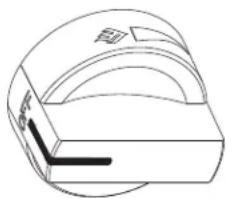
Push and turn the knob slowly counterclockwise to the ignite position (⚡) as shown in Fig. 11. Keep pushing until the burner lights and then release. Repeat for additional burners.
-
If burner does not light, immediately turn the control knob to the "OFF" position and repeat Step 2.
-
If burner does not light after Step 3, TURN OFF GAS SUPPLY and WAIT 15 MINUTES for the gas to disperse; then repeat Steps 1 and 2 or light with external flame.
natural_image
Technical line drawing of a mechanical component with no visible text or symbolsFig. 11
Shutdown instructions:
- Turn all control knobs to the "OFF" position.
- Turn gas supply off at the tank.
POST-ASSEMBLY
GRILL LIGHTING INSTRUCTION
IMPORTANT:
Lid must be open when lighting burners. TURN OFF GAS supply when not in use.
For Consumer Affairs, call: 1-800-851-8900.
TO LIGHT THE MAIN BURNERS BY MATCH:
If the burner will not light after several attempts, the burner can be match-lit.
Tools: Match holder (hanging under right-side shelf)
Usage:
- Read instructions before lighting.
- Open the lid and remove the cooking grids during lighting.
-
Turn a control knob to the ignite position (↓) as shown in Fig. 12.
-
Remove match holder from knot on side of base. Place a lighted match between the coils on the end of the match holder and hold next to the burner to ignite as shown in Fig. 12. If ignition does not occur in 5 seconds, turn the burner control knob OFF and contact Consumer Affairs.
-
For lighting the others burners, please repeat Steps 3 and 4.

natural_image
Technical line drawing of a portable grill with solar panel array and close-up insets showing internal components (no text or symbols)POST-ASSEMBLY
- Clean the grill often. A grease fire that may damage the grill may occur if the grill has not been cleaned frequently. See “Cleaning” in “Care and Maintenance” section for instructions.
- NEVER leave the grill unattended while using.
- Do not use water to extinguish the grease fire, because it may cause body injury. Turn knobs to OFF and LP tank off in case grease fire occurs.
- Grease fires cannot be put out by closing the lid. Turn knobs and LP tank to OFF IMMEDIATELY if any grease fire occurs.
WARNING
For your safety:
- Keep grill area clear and free from any flammable material.
- NEVER let children operate the grill or play near the grill.
- This grill is for OUTDOOR USE ONLY. NEVER use in a enclosed area such as a carport, porch, covered patio, garage, or under a surface that can catch fire.
- Do not block the ventilation holes in the four sides of the grill cart, since it may affect the combustion performance of the burner due to insufficient air.
- Use the grill at least 36" (91 cm) away from any wall or surface and 120" (305 cm) away from objects that may spark and ignite gas (i.e., live electrical appliances or pilot lights of water heaters).
- Do not use this grill on or under wood balconies.
- This grill is designed to use only LP gas. DO NOT use lava rock, briquettes, or charcoal in it.
- NEVER light the burner with the lid closed. Nonignited gas accumulated inside a closed grill may cause explosions.
- Check the burner flames periodically.
- Turn off the gas supply when the grill is not in use.
- Always turn off the LP tank completely and detach from the grill before moving.
POST-ASSEMBLY
The grill burners encompass the entire cooking area and are side-ported to minimize blockage from falling grease and debris. Above the burners are stainless-steel heat diffusers. The igniter knobs are located on the valve panel. Follow the lighting instructions printed on the control panel.
USING THE GRILL:
Grilling requires high heat for searing and proper browning. Most foods are cooked at the HI heat setting for the entire cooking time. However, when grilling large pieces of meat or poultry, it may be necessary to turn the heat to a lower setting after the initial browning. This cooks the food through without burning the outside. Foods cooked for a long time or basted with a sugary marinade may need a lower heat setting near the end of the cooking time.
- Make sure the grill has been leak-tested and is properly located.
- Remove any packing material.
- Light the grill burners using the instructions in this manual.
- Turn the control knob to HI and preheat the grill for 15 minutes, or to desired temperature.
- The grill lid is to be closed during the preheat period.
- Place food on the grill and cook to the desired doneness. Adjust heat setting, if necessary. The control knob may be set to any position between HI and LO.
- The grill is designed to grill efficiently without the use of lava rocks or briquettes of any kind. Heat is radiated by the stainless-steel flame tamers under the cast iron cooking grids.
- The hot grill sears the food, sealing in the juices. The longer the preheat, the faster the meat browns.
POST-ASSEMBLY
SAFETY TIPS
SAFETY TIPS:
- Always check for leaks after every LP tank change.
- Always check for leaks before each use.
- Use long barbeque tools to avoid burns.
- Check all gas supply fittings for leaks before each use. It is handy to keep a spray bottle of soapy water near the shut-off valve of the gas supply line. Spray all of the fittings. Bubbles indicate leaks.
- Disconnected LP tanks must have threaded valve plugs tightly installed and must not be stored in a building, garage, or any other enclosed areas.
- Turn off all control knobs and LP tank valve when the grill is not in use.
- If the appliance is stored indoors, the LP tank must be disconnected and removed from the grill.
- LP tanks must be stored outdoors in a well-ventilated area. Disconnected LP tanks in storage or being transported must have a safety cap.
- Never leave an LP tank in a recreational vehicle or boat which may become overheated by the sun.
- Do not store LP tank in or near an area where children play.
- For any other problems, see "Troubleshooting" or contact Consumer Affairs.
CARE AND MAINTENANCE
MAINTENANCE:
- Keep the grill area clear and free from combustible materials, gasoline, and other flammable vapors and liquids.
-
Keep the holes in the three sides of the cart clear and free from debris, ensuring the flow of combustion and ventilation air is unobstructed.
-
Visually check burner flames as following:
-
Remove cooking grids and flame tamers.
- Light burners.
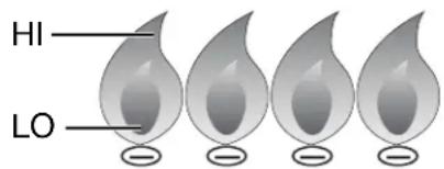
- Turn knobs from HI to LO and check the flame status. The flame in the LO position should be smaller than in the HI position, as figure shown below.
- Always check flame before each use. See “Troubleshooting” if any abnormal status is found.
- Visit our website, www.hamiltonbeach.com, or call Consumer Affairs at 1-800-851-8900 for replacement parts.
POST-ASSEMBLY
CARE AND MAINTENANCE
CLEANING
COOKING AREA CLEANING
The easiest way to clean the grill is to clean it immediately after turning off the flame when cooking is completed. Wear a barbeque mitt to protect your hand from the heat and steam. Dip a brass bristle barbeque brush in tap water and scrub the hot grill. Dip the brush frequently in the water. Steam, created as water contacts the hot grill, assists the cleaning process by softening any food particles. The food particles will fall and burn. Never immerse a hot part in water.
GRILL BURNER CLEANING
- Be sure the tank valve and the knobs are in the OFF position. Make sure the grill is cool.
- Clean the exterior of the burner with a wire brush. Clear stubborn scale with a metal scraper. Clear any clogged ports with a straightened paper clip. Never use a wooden toothpick since it may break off and clog the port.
- Please note that if insects or other obstructions are blocking the flow of gas through the burner, you will need to call Consumer Affairs.
VERY IMPORTANT: The orifice of the valve must be located in the center of the burner section after removal and cleaning. Otherwise, it may cause serious bodily injury and property damage. Swing the burner slightly after replacing to check whether it has been installed properly.
GREASE TRAY CLEANING
The grease tray should be emptied, wiped down periodically, and washed in a mild detergent and warm water solution. A small amount of sand may be placed in the bottom of the grease tray to absorb the grease.
SPIDER AND INSECT WARNING
Spiders and insects can nest in the burners after storing. These nests can cause fires inside the tube or beneath the grill. This is a very dangerous condition. Always clean the burners before use.
WHEN TO LOOK FOR SPIDERS
Inspect the burners at least once a year or immediately if any of the following conditions occur:
- Yellow flame with burning smell.
- Temperature will not rise.
- Heats unevenly.
- Burners make popping noises.
POST-ASSEMBLY
TROUBLESHOOTING
BEFORE CALLING FOR SERVICE:
Please check the following problems/solutions before contacting Consumer Affairs.
| PROBLEM | POSSIBLE CAUSE | SOLUTION |
| Burner will not light after turning and pushing the knobs. | Propane tank is empty. | Refill or replace propane tank. |
| Igniter deposited with cooking residues. | Use clean swab and alcohol to clean. | |
| Igniter damaged. | Replace. | |
| Igniter wires are loose or fall off. | Reconnect or replace with new igniter assembly with wires. | |
| Orifice blocked. | Check the orifice for blockage. | |
| Wire is shorting. | Replace with new igniter assembly with wires. | |
| Burner cannot light by match. | No gas | Open the LP tank valve or replace LP tank valve. |
| Gas flow is not smooth. | Clear burner tubes. | |
| Incorrect assembly between burner and valve | Reassemble. | |
| Yellow or orange flame with gas odor | Incomplete combustion | Call Consumer Affairs at 1-800-851-8900. |
| Low heat with knob in HI position | Gas hose bent or kinked. | Smooth out the hose. |
| Burner or orifice blocked. | Clear blockage. | |
| Low gas pressure | Call the gas dealer. | |
| Grill not preheated | Preheat the grill for 15 minutes. | |
| Flare-up | Excessive meat fat | Cut off fat before grilling. |
| Temperature too high | Adjust. | |
| Grease deposit | Clean. | |
| Flameout | High winds | Find a less windy place. |
| Flame lifting | Gas pressure too high | Call the gas dealer. |
| Flashback | Burner port blocked. | Clean burner port. |
| Grease fire | Grease accumulated in food. | Turn off knobs and LP tank valve.Leave lid open and let fire burn out.Clean the grill after cooling. |
POST-ASSEMBLY
FOOD SAFETY
- Always follow the following tips to enjoy safe and healthy outdoor grilling.
- Always use hot, soapy water to wash hands, surfaces, and utensils after processing raw meat.
- Always separate raw meat from cooked foods to avoid cross-contamination.
- Always use clean utensils to handle food.
- Always cook meat thoroughly to kill germs. Use a thermometer to inspect the inner temperature of the meat, if necessary.
- Place cooked foods and leftovers promptly into the refrigerator when done eating.
VERY IMPORTANT: DO NOT LEAVE THE GRILL UNATTENDED WHILE COOKING.
GRILL STORAGE
- Clean the grill. Turn the gas off at the supply cylinder.
- Store the grill in a well-ventilated, dry, outdoor area. Keep out of the reach of children when LP tank is connected to the grill.
- Store the grill indoors ONLY after the LP tank is turned off and removed. The LP tank must be stored outdoors out of the reach of children. NEVER store the tank in a building, garage, or any other enclosed area.
LIMITED WARRANTY
This warranty applies to products purchased in the U.S. and Canada. This is the only express warranty for this product and is in lieu of any other warranty or condition.
This product is warranted to be free from defects in material and workmanship for a period of five (5) years for the burners and one (1) year for all other parts from the date of original purchase. During this period, your exclusive remedy is repair or replacement of the part found to be defective, at our option; however, you are responsible for all costs associated with processing a warranty claim made more than thirty (30) days after the purchase date, including shipping and handling, for returning a part to us and our returning a part under this warranty to you. The original warranty period is not extended or renewed by the repair or replacement of any part.
This warranty does not cover igniter batteries, wear from normal use (such as paint loss, discoloration, or rust of the product or its parts), use not in conformity with the printed directions, or damage to the product resulting from accident, alteration, abuse, or misuse. This warranty extends only to the original consumer purchaser. Keep the original sales receipt, as proof of purchase is required to make a warranty claim. This warranty is void if the product is used for other than single-family household use, such as commercial or rental uses.
We exclude all claims for special, incidental, and consequential damages caused by breach of express or implied warranty. All liability is limited to the amount of the purchase price. Every implied warranty, including any statutory warranty or condition of merchantability or fitness for a particular purpose, is disclaimed except to the extent prohibited by law, in which case such warranty or condition is limited to the duration of this written warranty. This warranty gives you specific legal rights. You may have other legal rights that vary depending on where you live. Some states or provinces do not allow limitations on implied warranties or special, incidental, or consequential damages, so the foregoing limitations may not apply to you.
To make a warranty claim, do not return this appliance to the store. Please call 1.800.851.8900 in the U.S. or 1.800.267.2826 in Canada or visit hamiltonbeach.com in the U.S. or hamiltonbeach.ca in Canada. For faster service, locate the model, type, and series numbers on your appliance.
natural_image
Hamilton Beach electric grill with three control knobs and a black body (no visible text or symbols on the device itself)
Parrilla a Gas Tipo OG01
Hamilton Beach Brands, Inc. Glen Allen, Virginia 23060
TABLA DE CONTENIDOS
ANTES DE COMENZAR
MONTAJE
ANTES DEL MONTAJE
LEA Y SIGA LAS SIGUIENTES INSTRUCCIONES PARA DESEMPACAR CORRECTAMENTE LAS PIEZAS DE LA PARRILLA DE LA CAJA DE ENVÍO.
PASO 1:
natural_image
Simple line drawing of a wrench (no text or symbols)Llave (1)

M4 Nuez (4)
natural_image
Simple line drawing of a horizontal bar with two circular ends (no text or symbols)Portacerillos (1)
MONTAJE
PASOS DEL MONTAJE
PASO 1: Estante Inferior
natural_image
Technical line drawing of a mechanical assembly with wheels, mounting holes, and internal components (no text or symbols)Fig. 2
MONTAJE
PASOS DEL MONTAJE
PASO 3: Armazón del Carrito
natural_image
Technical line drawing of a mechanical device with internal components and mounting base (no text or symbols)Fig. 3
MONTAJE
PASOS DEL MONTAJE
natural_image
Technical line drawing of a mechanical device with mounting holes and internal components, labeled Fig. 5b (no text or symbols on the diagram itself)
natural_image
Technical line drawing of a mechanical device with an inset close-up showing internal components (no text or symbols)MONTAJE
PASOS DEL MONTAJE
PASO 6: Nudo de Nylon
Fig. 7
MONTAJE
PASOS DEL MONTAJE
natural_image
Technical line drawing of a mechanical device with a cylindrical housing and mounting base (no text or symbols)Fig. 9
DESPUÉS DEL MONTAJE
CONEXIÓN DE GAS
PARA SU SEGURIDAD:
natural_image
Technical line drawing of a mechanical component with no visible text or symbolsFig. 11
natural_image
Technical line drawing of a portable grill with solar panel array and close-up insets showing internal components (no text or symbols)DESPUÉS DEL MONTAJE

- STOP! TO PREVENT DAMAGING YOUR GRILL, READ THIS MANUAL FIRST FOR IMPORTANT UNPACKING AND ASSEMBLY INSTRUCTIONS!
- Hamilton Beach®
- Type OG01 Gas Grill
- TABLE OF CONTENTS
- BEFORE YOU BEGIN
- ASSEMBLY
- POST-ASSEMBLY
- !DANGER
- WARNING
- MESSAGE TO OUR USERS
- SAFETY SYMBOLS
- CAUTION
- CALIFORNIA PROPOSITION 65
- INSTALLATION/SAFETY PRECAUTIONS
- READ THIS SECTION FIRST BEFORE INSTALLING THE GRILL
- BEFORE THE ASSEMBLY
- READ AND FOLLOW THE INSTRUCTIONS BELOW TO CORRECTLY UNPACK GRILL PARTS FROM SHIPPING BOX.
- STEP 1:
- STEP 2:
- PLEASE READ AND FOLLOW THESE INSTRUCTIONS CAREFULLY STEP BY STEP
- Tools Required:
- Phillips screwdriver (not provided)
- ASSEMBLY STEPS
- STEP 1: Bottom Shelf
- STEP 2: Cart
- STEP 3: Cart Frame
- STEP 4: Grill Head to Cart
- STEP 5: Side Shelves
- STEP 6: Nylon Knot
- STEP 7: Grease Cup
- STEP 8: Cooking Grates
- GAS CONNECTION
- ONLY USE THE REGULATOR AND HOSE ASSEMBLY PROVIDED WITH THIS GRILL. REPLACEMENT PRESSURE REGULATORS AND HOSE ASSEMBLIES MUST BE THOSE SUPPLIED BY THE MANUFACTURER.
- LP TANK REQUIREMENTS – THE LP TANK USED WITH YOUR GRILL MUST MEET THE FOLLOWING:
- LP TANK VALVE USED MUST MEET THE FOLLOWING:
- FOR YOUR SAFETY:
- CONNECT THE REGULATOR TO THE LP TANK - VERY IMPORTANT:
- Failure to follow these instructions exactly could start a fire causing death or serious injury.
- VERY IMPORTANT:
- TO DISCONNECT LP GAS TANK:
- LEAK TESTING
- GENERAL
- BEFORE TESTING
- TO TEST
- FINAL INSTALLATION CHECKLIST
- GRILL LIGHTING INSTRUCTION
- VERY IMPORTANT: ALWAYS INSPECT THE HOSE PRIOR TO EACH USE.
- BEFORE LIGHTING:
- TO LIGHT MAIN BURNERS OF THE GRILL:
- Read instructions before lighting.
- Shutdown instructions:
- IMPORTANT:
- TO LIGHT THE MAIN BURNERS BY MATCH:
- USING THE GRILL:
- SAFETY TIPS
- SAFETY TIPS:
- CARE AND MAINTENANCE
- MAINTENANCE:
- CLEANING
- COOKING AREA CLEANING
- GRILL BURNER CLEANING
- GREASE TRAY CLEANING
- SPIDER AND INSECT WARNING
- WHEN TO LOOK FOR SPIDERS
- TROUBLESHOOTING
- BEFORE CALLING FOR SERVICE:
- FOOD SAFETY
- GRILL STORAGE
- LIMITED WARRANTY
- Parrilla a Gas Tipo OG01
- TABLA DE CONTENIDOS
- ANTES DE COMENZAR
- MONTAJE
- ANTES DEL MONTAJE
- LEA Y SIGA LAS SIGUIENTES INSTRUCCIONES PARA DESEMPACAR CORRECTAMENTE LAS PIEZAS DE LA PARRILLA DE LA CAJA DE ENVÍO.
- PASO 1:
- PASOS DEL MONTAJE
- PASO 1: Estante Inferior
- PASO 3: Armazón del Carrito
- PASO 6: Nudo de Nylon
- DESPUÉS DEL MONTAJE
- CONEXIÓN DE GAS
- PARA SU SEGURIDAD:
Brand : HAMILTON BEACH
Model : 84131
Category : Barbecue