R-091DYGN - Air-conditioner Tatung - Free user manual and instructions
Find the device manual for free R-091DYGN Tatung in PDF.

User questions about R-091DYGN Tatung
0 question about this device. Answer the ones you know or ask your own.
Ask a new question about this device
Download the instructions for your Air-conditioner in PDF format for free! Find your manual R-091DYGN - Tatung and take your electronic device back in hand. On this page are published all the documents necessary for the use of your device. R-091DYGN by Tatung.
USER MANUAL R-091DYGN Tatung
natural_image
Front view of a white Siemens air conditioner unit with control panel (no visible text or symbols)OWNER'S MANUAL
Split Air Conditioner

Content
Read Before Operation
Safety 1
Name of Parts 6
Screen Operation Guide
Buttons on remote controller 7
Introduction for icons on display screen 7
Introduction for buttons on remote controller....8
Function introduction for combination buttons.... 12
Operation guide....13
Replacement of batteries in remote controller.... 13
Emergency operation 14
Maintenance
Clean and maintenance....14
Troubleshooting
Malfunction analysis 17
Installation Notice
Installation dimension diagram....21
Tools for installation....22
Selection of installation location 22
Requirements for electric connection 23
Installation
Installation of indoor unit....24
Installation of outdoor unit 29
Vacuum pumping....32
Leakage detection 32
Check after installation 33
Test and operation
Test operation....33
Attachment
Configuration of connection pipe 34
Pipe expanding method....36

WARNING
Operation and Maintenance
•Children shall not play with the appliance.
- Cleaning and user maintenance shall not be made by children without supervision.
- Do not connect air conditioner to multi-purpose socket. Otherwise, it may cause fire hazard.
- Do disconnect power supply when cleaning air conditioner. Otherwise, it may cause electric shock.
- If the supply cord is damaged, it must be replaced by the manufacturer, its service agent or similarly qualified persons in order to avoid a hazard.
- Do not wash the air conditioner with water to avoid electric shock.
- Do not spray water on indoor unit. It may cause electric shock or malfunction.
•After removing the filter, do not touch fins to avoid injury.
- Do not use fire or hair dryer to dry the filter to avoid deformation or fire hazard.

WARNING
- Do not repair air conditioner by yourself. It may cause electric shock or damage. Please contact dealer when you need to repair air conditioner.
- Do not extend fingers or objects into air inlet or air outlet. It may cause personal injury or damage.
- Do not block air outlet or air inlet. It may cause malfunction.
- Do not spill water on the remote controller, otherwise the remote controller may be broken.
- When below phenomenon occurs, please turn off air conditioner and disconnect power immediately, and then contact the dealer or qualified professionals for service.
• Power cord is overheating or damaged. - There's abnormal sound during operation.
• Circuit break trips off frequently.
• Air conditioner gives off burning smell. - Indoor unit is leaking.
- If the air conditioner operates under abnormal conditions, it may cause malfunction, electric shock or fire hazard.
- When turning on or turning off the unit by emergency operation switch, please press this switch with an insulating object other than metal.
- Do not step on top panel of outdoor unit, or put heavy objects. It may cause damage or personal injury.

WARNING
Attachment
• Installation must be performed by qualified professionals. Otherwise, it may cause personal injury or damage.
- Must follow the electric safety regulations when installing the unit.
- According to the local safety regulations, use qualified power supply circuit and circuit break.
- Do install the circuit break. If not, it may cause malfunction.
- An all-pole disconnection switch having a contact separation of at least 3mm in all poles should be connected in fixed wiring.
- Including a circuit break with suitable capacity, please note the following able: Air switch should be included with magnet buckle and heating buckle function, it can protect the circuit-short and overload.
• Air Conditioner should be properly grounded. Incorrect grounding may cause electric shock.
- Don't use unqualified power cord.
- Make sure the power supply matches with the requirement of air conditioner. Unstable power supply or incorrect wiring or malfunction. Please install proper power supply cables before using the air conditioner.
- Properly connect the live wire, neutral wire and grounding wire of power socket.
- Be sure to cut off the power supply before proceeding any work related to electricity and safety.

WARNING
- Do not put through the power before finishing installation.
- The temperature of refrigerant circuit will be high, please keep the interconnection cable away from the copper tube.
- The appliance shall be installed in accordance with national wiring regulations.
• Installation must be performed in accordance with the requirement of NEC and CEC by authorized personnel only. - The yellow-green wire in air conditioner is grounding wire, which can't be used for other purposes.
- The grounding resistance should comply with national electric safety regulations.
- The appliance must be positioned so that the plug is accessible.
- All wires of indoor unit and outdoor unit should be connected by a professional.
- If the length of power connection wire is insufficient, please contact the supplier for a new one. Avoid extending the wire by yourself.

WARNING
- For air conditioners with plug, the plug should be reachable after finishing installation.
- For air conditioners without plug, a circuit break must be installed in the line.
- If you need to relocate the air conditioner to another place, only the qualified person can perform the work. Otherwise, it may cause personal injury or damage.
- Select a location which is out of reach for children and far away from animals or plants. If it is unavoidable, please add fence for safety purpose.
- The indoor unit should be installed close to the wall.
Working temperature range
| Indoor side DB/WB(°C) | Outdoor side DB/WB(°C) | |
| Maximum cooling | 26.7/19.4 | 46.1/23.9 |
| Maximum heating | 26.7/- | 23.9/18.3 |
| Indoor side DB/WB(°F) | Outdoor side DB/WB(°F) | |
| Maximum cooling | 80.06/66.92 | 114.98/75.02 |
| Maximum heating | 80.06/- | 75.02/64.94 |
NOTICE:
- The operating temperature range (outdoor temperature) is -18 °C\~46.1 °C (-0.4°F\~114.9°F).
Name of Parts
FT-091DYGN
R-091DYGN
NOTICE:
Actual product may be different from above graphics, please refer to actual products.
Buttons on remote controller
1 ON/OFF button
2 MODE button
3 +/- button
4 FAN button
5 ➕ button
6 CLOCK button
7 TIMER ON/TIMER OFF button
8 X-FAN button
Note: X-FAN is the same with BLOW
9 TEMP button
10 TURBO button
11 LIGHT button
12 SLEEP button
Introduction for icons on display screen
Introduction for buttons on remote controller
Note:
- After plugging in the power, the air conditioner will give out a sound. Operation indicator "⏻" is ON (red indicator). After that, you can operate the air conditioner by using remote controller.
1 ON/OFF button
Press this button can turn on or turn off the air conditioner. After turning on the air conditioner, operation indicator "() on indoor unit's display is ON (green indicator. The colour is different for different models), and indoor unit will give out a sound.
2 MODE button
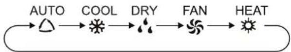
Press this button to select your required operation mode.
flowchart
graph LR
    A["AUTO"] --> B["COOL"]
    B --> C["DRY"]
    C --> D["FAN"]
    D --> E["HEAT"]
- When selecting auto mode, air conditioner will start auto operation according to indoor ambient temperature. Set temperature can't be adjusted and will not be displayed as well. Press "FAN" button can adjust fan speed. Press "→" button can adjust fan blowing angle.
- After selecting cool mode, air conditioner will operate under cool mode. Cool indicator "✿" on indoor unit is ON. Press "+" or "-" button to adjust set temperature. Press "FAN" button to adjust fan speed. Press "*" button to adjust fan blowing angle.
- When selecting dry mode, the air conditioner operates at low speed under dry mode. Dry indicator " 🔊" on indoor unit is ON. Under dry mode, fan speed can't be adjusted. Press " ➡" button to adjust fan blowing angle.
- When selecting fan mode, the air conditioner will only blow fan, no cooling and no heating. All indicators are OFF. Press "FAN" button to adjust fan speed. Press "→" button to adjust fan blowing angle.
- When selecting heating mode, the air conditioner operates under heat mode. Heat indicator "☀️" on indoor unit is ON. Press "+" or "-" button to adjust set temperature. Press "FAN" button to adjust fan speed. Press "⚡" button to adjust fan blowing angle. (Cooling only unit won't receive heating mode signal. If setting heat mode with remote controller, press ON/OFF button can't start up the unit).
Note:
- To prevent cold air, after starting up heating mode, the unit will delay 1\~5 minutes to blow air (actual delay time is depend on indoor ambient temperature).
- Set temperature range from remote controller: 16\~30°C (60.8\~86°F); Fan speed: auto, low speed, medium speed, high speed.
Introduction for buttons on remote controller
3 +/- button
- Press "+" or "-" button once increase or decrease set temperature 1°C (1.8°F). Holding "+" or "-" button, 2s later, set temperature on remote controller will change quickly. On releasing button after setting is finished, temperature indicator on indoor unit will change accordingly. (Temperature can't be adjusted under auto mode)
- When setting TIMER ON, TIMER OFF or CLOCK, press "+" or "-" button to adjust time. (Refer to CLOCK, TIMER ON, TIMER OFF buttons) When setting TIMER ON, TIMER OFF or CLOCK, press "+" or "-" button to adjust time. (Refer to CLOCK, TIMER ON, TIMER OFF buttons)
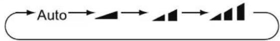
4 FAN button
Pressing this button can set fan speed circularly as: auto (AUTO), low(▲), medium(▲), high(▲).
flowchart
graph LR
    A["Auto"] --> B["△"]
    B --> C["△"]
    C --> D["△"]
Note:
- Under AUTO speed, the IDU fan motor will adjust the fan speed (high, medium or low speed) according to ambient temperature.
- Fan speed under dry mode is low speed.
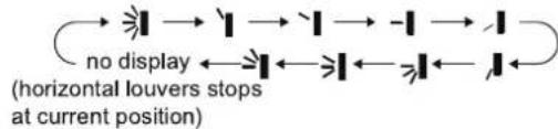
5 button
Press this button can select up&down swing angle. Fan blow angle can be selected circularly as below:
flowchart
graph TD
    A["->"] --> B["1"] --> C["1"] --> D["-"] --> E["1"]
    F["->"] --> G["1"] <--] --> H["1"] <--] <--] <--] <--] <--] <--] <--] <--] <--] <--] <--] <--] <--] <--] <--] <--] <--] <--] <--] <--] <--] <--] <--] <--] <--] <--] <--] <--] <--] <--] <--] <--] <--] <--] <--] <--] <--] <--] <--] <--] <--] <--] <--] <--] <--] <--] <--] <--] <--] <--] <--> (horizontal louvers stops at current position)
- When selecting "☐", air conditioner is blowing fan automatically. Horizontal louver will automatically swing up & down at maximum angle.
- When selecting "1、2、3、4、5、6",air conditioner is blowing fan at fixed position. Horizontal louver will stop at the fixed position.
- When selecting "≥1, ≥2, ≥3", air conditioner is blowing fan at fixed angle. Horizontal louver will send air at the fixed angle.
- Hold "→" button above 2s to set your required swing angle. When reaching your required angle, release the button.
Note:
- "">1,">1,">1" may not be available. When air conditioner receives this signal, the air conditioner will blow fan automatically.
Introduction for buttons on remote controller
6 CLOCK button
Press this button to set clock time. "☐" icon on remote controller will blink. Press "+" or "-" button within 5s to set clock time. Each pressing of "+" or "-" button, clock time will increase or decrease 1 minute. If hold "+" or "-" button, 2s later, time will change quickly. Release this button when reaching your required time. Press "CLOCK" button to confirm the time. "☐" icon stops blinking.
Note:
- Clock time adopts 24-hour mode.
- The interval between two operation can't exceeds 5s. Otherwise, remote controller will quit setting status. Operation for TIMER ON/TIMER OFF is the same.
7 TIMER ON / TIMER OFF button
- TIMER ON button
"TIMER ON" button can set the time for timer on. After pressing this button, "💡" icon disappears and the word "ON" on remote controller blinks. Press "+" or "-" button to adjust TIMER ON setting. After each pressing "+" or "-" button, TIMER ON setting will increase or decrease 1min. Hold "+" or "-" button, 2s later, the time will change quickly until reaching your required time.
Press "TIMER ON" to confirm it. The word "ON" will stop blinking. "💡" icon resumes displaying. Cancel TIMER ON: Under the condition that TIMER ON is started up, press "TIMER ON" button to cancel it.
- TIMER OFF button
"TIMER OFF" button can set the time for timer off. After pressing this button, "💡" icon disappears and the word "OFF" on remote controller blinks. Press "+" or "-" button to adjust TIMER OFF setting. After each pressing "+" or "-" button, TIMER OFF setting will increase or decrease 1min. Hold "+" or "-" button, 2s later, the time will change quickly until reaching your required time.
Press "TIMER OFF" word "OFF" will stop blinking. "💡" icon resumes displaying. Cancel TIMER OFF. Under the condition that TIMER OFF is started up, press "TIMER OFF" button to cancel it.
Note:
- Under on and off status, you can set TIMER OFF or TIMER ON simultaneously.
- Before setting TIMER ON or TIMER OFF, please adjust the clock time.
- After starting up TIMER ON or TIMER OFF, set the constant circulating valid. After that, air conditioner will be turned on or turned off according to setting time. ON/OFF button has no effect on setting. If you don't need this function, please use remote controller to cancel it.
Introduction for buttons on remote controller
8 X-FAN button
Press this button under cool and dry mode to start up x-fan function, and " ✉ " icon on remote controller will be displayed. Press this button again to cancel x-fan function, and " ✉ " icon will disappear.
Note:
- When x-fan function is on, if the air conditioner is turned off, indoor fan will still operate at low speed for a while to blow the residual water inside the air duct.
- During x-fan operation, press X-FAN button to turn off x-fan function. Indoor fan will stop operation immediately.
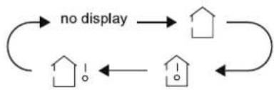
9 TEMP button
By pressing this button, you can see indoor set temperature, indoor ambient temperature or outdoor ambient temperature on indoor unit's display. The setting on remote controller is selected circularly as below:
flowchart
graph TD
    A["House icon"] --> B["House icon"]
    B --> C["House icon"]
    C --> A
    A -->|no display| B
    B -->|no display| C
- When selecting "☐" or no display with remote controller, temperature indicator on indoor unit displays set temperature.
- When selecting " ", with remote controller, temperature indicator on indoor unit displays indoor ambient temperature.
- When selecting "☐" with remote controller, temperature indicator on indoor unit displays outdoor ambient temperature.
Note:
- Outdoor temperature display is not available for some models. At that time, indoor unit receives "☐" signal, while it displays indoor set temperature.
- It's defaulted to display set temperature when turning on the unit. There is no display in the remote controller.
- Only for the models whose indoor unit has dual-8 display.
- When selecting displaying of indoor or outdoor ambient temperature, indoor temperature indicator displays corresponding temperature and automatically turn to display set temperature after three or five seconds.
10 TURBO button
Under COOL or HEAT mode, press this button to turn to quick COOL or quick HEAT mode. "©" icon is displayed on remote controller. Press this button again to exit turbo function and "©" icon will disappear.
Introduction for buttons on remote controller
11 SLEEP button
Under COOL, HEAT or DRY mode, press this button to start up sleep function. " 🔊" icon is displayed on remote controller. Press this button again to cancel sleep function and " 🔊" icon will disappear.
12 LIGHT button
Press this button to turn off display light on indoor unit. "💡" icon on remote controller disappears. Press this button again to turn on display light. "💡" icon is displayed.
Function introduction for combination buttons
Child lock function
Press "+" and "-" simultaneously to turn on or turn off child lock function. When child lock function is on, "☐" icon is displayed on remote controller. If you operate the remote controller, the "☐" icon will blink three times without sending signal to the unit.
Temperature display switchover function
Under OFF status, press "-" and "MODE" buttons simultaneously to switch temperature display between °C and °F.
Operation Guide
- Plug in power cord, press "ON/OFF" button on remote controller to turn on the air conditioner.
- Press "MODE" button to select your required mode: AUTO, COOL, DRY, FAN, HEAT.
- Press "+" or "-" button to set your required temperature. (Temperature can't be adjusted under auto mode).
- Press "FAN" button to set your required fan speed: auto, low, medium and high speed.
- Press "→" button to select fan blowing angle.
Replacement of batteries in remote controller
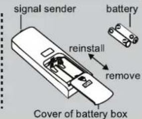
- Press the back side of remote controller marked with "■", as shown in the fig, and then push out the cover of battery box along the arrow direction.
- Replace two 7# (AAA 1.5V) dry batteries, and make sure the position of "+" polar and "-" polar are correct.
- Reinstall the cover of battery box.
NOTICE
- During operation, point the remote control signal sender at the receiving window on indoor unit.
- The distance between signal sender and receiving window should be no more than 8m (26.24 ft), and there should be no obstacles between them.
- Signal may be interfered easily in the room where there is fluorescent lamp or wireless telephone; remote controller should be close to indoor unit during operation.
- Replace new batteries of the same model when replacement is required.
- When you don't use remote controller for a long time, please take out the batteries.
- If the display on remote controller is fuzzy or there's no display, please replace batteries.
Emergency Operation
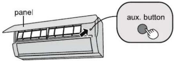
If remote controller is lost or damaged, please use auxiliary button to turn on or turn off the air conditioner. The operation in details are as below: As shown in the fig. Open panel, press aux. button to turn on or turn off the air conditioner. When the air conditioner is turned on, it will operate under auto mode.
Clean and Maintenance

WARNING
■ Turn off the air conditioner and disconnect the power before cleaning the air conditioner to avoid electric shock.
■ Do not wash the air conditioner with water to avoid electric shock.
■ Do not use volatile liquid to clean the air conditioner.
Clean surface of indoor unit
When the surface of indoor unit is dirty, it is recommended to use a soft dry cloth or wet cloth to wipe it.
NOTICE:
- Do not remove the panel when cleaning it.
Clean and Maintenance
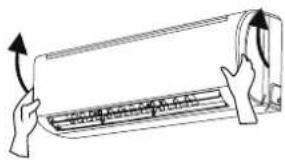
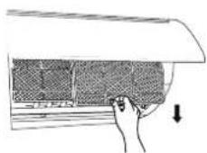
Clean filter
Open panel
Pull out the panel to a certain angle as shown in the fig.
natural_image
Illustration of hands holding a scroll with an arrow indicating upward motion (no text or symbols)3
Clean filter
- Use dust catcher or water to clean the filter.
- When the filter is very dirty, use the water (below 45°C) to clean it, and then put it in a shady and cool place to dry.
2
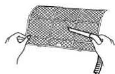
Remove filter
Remove the filter as indicated in the fig.
natural_image
Hand placing a component into a fan or panel, with a downward arrow indicating motion (no text or symbols present)4
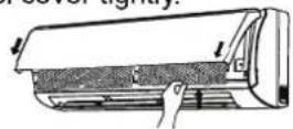
Install filter
Install the filter and then close the panel cover tightly.

WARNING
■ The filter should be cleaned every three months. If there is much dust in the operation environment, clean frequency can be increased.
■ After removing the filter, do not touch fins to avoid injury.
■ Do not use fire or hair dryer to dry the filter to avoid deformation or fire hazard.
Clean and Maintenance
NOTICE: Checking before use-season
- Check whether air inlets and air outlets are blocked.
- Check whether circuit break, plug and socket are in good condition.
- Check whether filter is clean.
- Check whether mounting bracket for outdoor unit is damaged or corroded. If yes, please contact dealer.
- Check whether drainage pipe is damaged.
NOTICE: Checking after use-season
- Disconnect power supply.
- Clean filter and indoor unit's panel.
- Check whether mounting bracket for outdoor unit is damaged or corroded. If yes, please contact dealer.
Notice for recovery
- Many packing materials are recyclable materials.
Please dispose them in appropriate recycling unit. - If you want to dispose the air conditioner, please contact local dealer or consultant service center for the correct disposal method.
Troubleshooting
General phenomenon analysis
Please check below items before asking for maintenance. If the malfunction still can't be eliminated, please contact local dealer or qualified professionals.
| Problem | Check items | Solution |
| Indoor unit can't receive remote controller's signal or remote controller has no action. | Whether it's interfered severely (such as static electricity,stable voltage)? | Pull out the plug. Reinsert the plug after about 3min, and then turn on the unit again. |
| Whether remote controller is within the signal receiving range? | Signal receiving range is 8m (26.24ft). | |
| Whether there are obstacles? | Remove obstacles. | |
| Whether remote controller is pointing at the receiving window? | Select proper angle and point the remote controller at the receiving window on indoor unit. | |
| Is sensitivity of remote controller low; fuzzy display and no display? | Check the batteries. If the power of batteries is too low, please replace them. | |
| No display when operating remote controller? | Check whether remote controller appears to be damaged. If yes, replace it. | |
| Fluorescent lamp in room? | Take the remote controller close to indoor unit.Turn off the fluorescent lamp and then try it again. |
| No air emitted from indoor unit | Air inlet or air outlet of indoor unit is blocked? | Eliminate obstacles. |
| Under heating mode, indoor temperature is reached to set temperature? | After reaching to set temperature, indoor unit will stop blowing out air. | |
| Heating mode is turned on just now? | In order to prevent blowing out cold air, indoor unit will be started after delaying for several minutes, which is a normal phenomenon. |
Troubleshooting
| Problem | Check items | Solution |
| Air conditioner can't operate | Power failure? | Wait until power recovery. |
| Is plug loose? | Reinsert the plug. | |
| Circuit break trips off or fuse is burnt out? | Ask professional to replace circuit break or fuse. | |
| Wiring has malfunction? | Ask professional to replace it. | |
| Unit has restarted immediately after stopping operation? | Wait for 3min, and then turn on the unit again. | |
| Whether the function setting for remote controller is correct? | Reset the function. | |
| Mist is emitted from indoor unit's air outlet | Indoor temperature and humidity is high? | Because indoor air is cooled rapidly. After a while, indoor temperature and humidity will be decrease and mist will disappear. |
| Set temperature can't be adjusted | Unit is operating under auto mode? | Temperature can't be adjusted under auto mode. Please switch the operation mode if you need to adjust temperature. |
| Your required temperature exceeds the set temperature range? | Set temperature range: 16°C~30°C (60.8~86°F). | |
| Cooling (heating) effect is not good. | Voltage is too low? | Wait until the voltage resumes normal. |
| Filter is dirty? | Clean the filter. | |
| Set temperature is in proper range? | Adjust temperature to proper range. | |
| Door and window are open? | Close door and window. |
Troubleshooting
| Problem | Check items | Solution |
| Odors are emitted | Whether there's odors source, such as furniture and cigarette, etc. | Eliminate the odors source.Clean the filter. |
| Air conditioner operates abnormally | Whether there's interference, such as thunder, wireless devices, etc. | Disconnect power, put back power, and then turn on the unit again. |
| Outdoor unit has vapor | Heating mode is turned on? | During defrosting under heating mode, it may generate vapor, which is a normal phenomenon. |
| "Water flowing" noise | Air conditioner is turned on or turned off just now? | The noise is the sound of refrigerant flowing inside the unit, which is a normal phenomenon. |
| Cracking noise | Air conditioner is turned on or turned off just now? | This is the sound of friction caused by expansion and/or contraction of panel or other parts due to the change of temperature. |
Troubleshooting
Error Code
- When air conditioner status is abnormal, temperature indicator on indoor unit will blink to display corresponding error code. Please refer to below list for identification of error code.
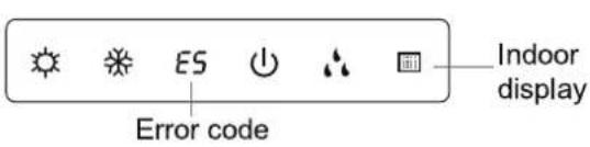
Above indicator diagram is only for reference. Please refer to actual product for the actual indicator and position.
| Error code | Troubleshooting |
| Heating indicator ON 10s OFF 0.5s | Means defrosting status. It's the normal phenomenon. |
| E5 | It can be eliminated after restarting the unit. If not, please contact qualified professionals for service. |
| H6 | It can be eliminated after restarting the unit. If not, please contact qualified professionals for service. |
| C5 | Please contact qualified professionals for service. |
| F1 | Please contact qualified professionals for service. |
| F2 | Please contact qualified professionals for service. |
| E6 | It can be eliminated after restarting the unit. If not, please contact qualified professionals for service. |
Note: If there're other error codes, please contact qualified professionals for service.

WARNING
■ When below phenomenon occurs, please turn off air conditioner and disconnect power immediately, and then contact the dealer or qualified professionals for service.
- Power cord is overheating or damaged.
- There's abnormal sound during operation.
- Circuit break trips off frequently.
• Air conditioner gives off burning smell.
- Indoor unit is leaking.
■ Do not repair or refit the air conditioner by yourself.
■ If the air conditioner operates under abnormal conditions, it may cause malfunction, electric shock or fire hazard.
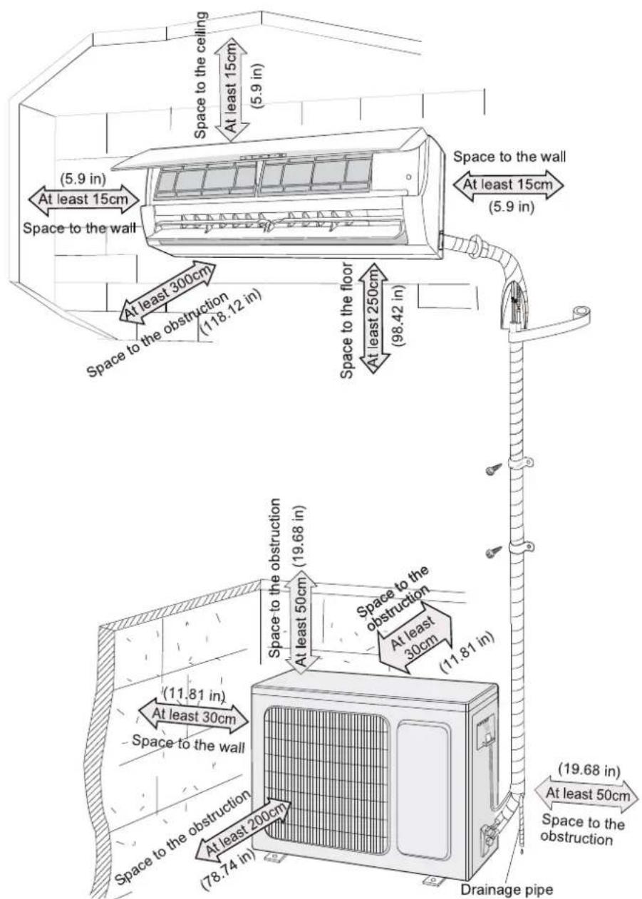
Installation dimension diagram
Tools for Installation
| 1 Level meter | 2 Screw driver | 3 Impact drill | |
| 4 Drill head | 5 Pipe expander | 6 Torque wrench | |
| 7 Open-end wrench | 8 Pipe cutter | 9 Leakage detector | |
| 10 Vacuum pump | 11 Pressure meter | 12 Universal meter | |
| 13 Inner hexagon spanner | 14 Measuring tape | ||
Note:
- Please contact the local agent for installation.
- Don't use unqualified power cord.
Selection of installation location
Basic requirement
Installing the unit in the following places may cause malfunction. If it is unavoidable, please consult the local dealer:
- The place with strong heat sources, vapors, flammable or explosive gas, or volatile objects spread in the air.
- The place with high-frequency devices (such as welding machine, medical equipment).
- The place near coast area.
- The place with oil or fumes in the air.
- The place with sulfureted gas.
- Other places with special circumstances.
- Do not use the unit in the immediate surroundings of a laundry a bath a shower or a swimming pool.
Indoor unit
- There should be no obstruction near air inlet and air outlet.
- Select a location where the condensation water can be dispersed easily and won't affect other people.
- Select a location which is convenient to connect the outdoor unit and near the power socket.
- Select a location which is out of reach for children.
- The location should be able to withstand the weight of indoor unit and won't increase noise and vibration.
- The appliance must be installed 8.2 ft above floor.
- Don't install the indoor unit right above the electric appliance.
- Please try your best to keep way from fluorescent lamp.
Outdoor unit
- Select a location where the noise and outflow air emitted by the outdoor unit will not affect neighborhood.
- The location should be well ventilated and dry, in which the outdoor unit won't be exposed directly to sunlight or strong wind.
- The location should be able to withstand the weight of outdoor unit.
- Make sure that the installation follows the requirement of installation dimension diagram.
- Select a location which is out of reach for children and far away from animals or plants. If it is unavoidable, please add the fence for safety purpose.
Requirements for Electric Connection
Safety Precaution
- Must follow the electric safety regulations when installing the unit.
- According to the local safety regulations, use qualified power supply circuit and circuit break.
- Make sure the power supply matches with the requirement of air conditioner. Unstable power supply or incorrect wiring or malfunction. Please install proper power supply cables before using the air conditioner.
- Properly connect the live wire, neutral wire and grounding wire of power socket.
- Be sure to cut off the power supply before proceeding any work related to electricity and safety.
- Do not put through the power before finishing installation.
- If the supply cord is damaged, it must be replaced by the manufacturer, its service agent or similarly qualified persons in order to avoid a hazard.
- The temperature of refrigerant circuit will be high, please keep the interconnection cable away from the copper tube.
- The appliance shall be installed in accordance with national wiring regulations.
- Installation must be performed in accordance with the requirement of NEC and CEC by authorized personnel only.
Grounding requirement
- The air conditioner is the first class electric appliance. It must be properly grounding with specialized grounding device by a professional. Please make sure it is always grounded effectively, otherwise it may cause electric shock.
- The yellow-green wire in air conditioner is grounding wire, which can't be used for other purposes.
- The grounding resistance should comply with national electric safety regulations.
- The appliance must be positioned so that the plug is accessible.
- An all-pole disconnection switch having a contact separation of at least 3mm in all poles should be connected in fixed wiring.
- Including an circuit break with suitable capacity, please note the following table. Circuit break should be included magnet buckle and heating buckle function, it can protect the circuit-short and overload. (Caution: please do not use the fuse only for protect the circuit)
| Air-conditioner | Air switch capacity |
| 09K | 35A |
| 12K | 35A |
Installation of Indoor Unit
Step One: Choosing installation location
Recommend the installation location to the client and then confirm it with the client.
Step Two: Install wall-mounting frame
- Hang the wall-mounting frame on the wall; adjust it in horizontal position with the level meter and then point out the screw fixing holes on the wall.
- Drill the screw fixing holes on the wall with impact drill (the specification of drill head should be the same as the plastic expansion particle) and then fill the plastic expansion particles in the holes.
- Fix the wall-mounting frame on the wall with tapping screws (ST4.2X25TA) and then check if the frame is firmly installed by pulling the frame. If the plastic expansion particle is loose, please drill another fixing hole nearby.
Step Three: Open piping hole
- Choose the position of piping hole according to the direction of outlet pipe. The position of piping hole should be a little lower than the wall-mounted frame, shown as below.
- Open a piping hole with the diameter of 55mm(2.16 in) or 70mm(2.75 in) on the selected outlet pipe position. In order to drain smoothly, slant the piping hole on the wall slightly downward to the outdoor side with the gradient of 510^ .
Installation of Indoor Unit
Note:
- Pay attention to dust prevention and take relevant safety measures when opening the hole.
- The plastic expansion particles are not provided and should be bought locally.
Step Four: Outlet pipe
- The pipe can be led out in the direction of right, rear right, left or rear left.

- When select leading out the pipe from left or right, please cut off the corresponding hole on the bottom case.
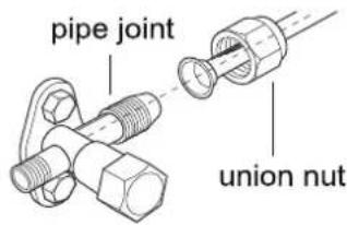
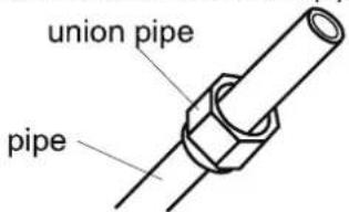
Step Five: Connect the pipe of indoor unit
-
Aim the pipe joint at the corresponding bellmouth.
-
Pretightening the union nut with hand.
-
Adjust the torque force by referring to the following sheet. Place the open-end wrench on the pipe joint and place the torque wrench on the union nut. Tighten the union nut with torque wrench.
Installation of Indoor Unit
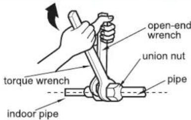
| Hex nut diameter | Tightening torque (N·m) |
| 6(1/4") | 15~20 |
| 9.52(3/8") | 30~40 |
| 12(1/2") | 45~55 |
| 16(5/8") | 60~65 |
| 19(3/4") | 70~75 |
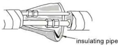
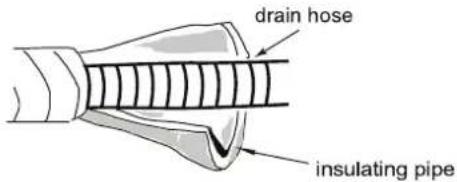
- Wrap the indoor pipe and joint of connection pipe with insulating pipe, and then wrap it with tape.
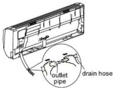
Step Six: Install drain hose
-
Connect the drain hose to the outlet pipe of indoor unit.
-
Bind the joint with tape.
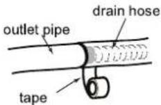
Note:
- Add insulating pipe in the indoor drain hose in order to prevent condensation.
● The plastic expansion particles are not provided.
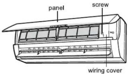
Step Seven: Connect wire of indoor unit
- Open the panel, remove the screw on the wiring cover and then take down the cover.
Installation of Indoor Unit
- Make the power connection cord go through the cable-cross hole at the back of indoor unit and then pull it out from the front side.
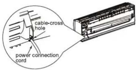
- Remove the wire clip; connect the power connection cord to the wiring terminal according to the color; tighten the screws and then fix the power connection cord with wire clip.
If there is no wired controller in the product you bought, you should put the wire fixed by the wire clip inside of the electric box first before connecting the power connection cord.
-
Put wiring cover back and then tighten the screw.
-
Close the panel.
Note:
- All wires of indoor unit and outdoor unit should be connected by a professional.
- If the length of power connection cord is insufficient, please contact the supplier for a new one. Avoid extending the cord by yourself.
- For the air conditioner with plug, the plug should be reachable after finishing installation.
- For the air conditioner without plug, an circuit break must be installed in the line. The air switch should be all-pole parting and the contact parting distance should be more than 3mm (0.11 inch).
Installation of Indoor Unit
Step Eight: Bind up pipe
- Bind up the connection pipe, power cord and drain hose with the band.
- Reserve a certain length of drain hose and power cord for installation when binding them. When binding to a certain degree, separate the indoor power and then separate the drain hose.
joepps!qpxfs!dpse
- Bind them evenly.
- The liquid pipe and gas pipe should be bound separately at the end.
Note:
- The power cord and control wire can't be crossed or winding.
- The drain hose should be bound at the bottom.
Step Nine: Hang the indoor unit
- Put the bound pipes in the wall pipe and then make them pass through the wall hole.
- Hang the indoor unit on the wall-mounting frame.
- Stuff the gap between pipes and wall hole with sealing gum.
- Fix the wall pipe.
- Check if the indoor unit is installed firmly and closed to the wall.

Note:
- Do not bend the drain hose too excessively in order to prevent blocking.
Installation of Outdoor Unit
Step One: Fix the support of outdoor unit (select it according to the actual installation situation)
-
Select installation location according to the house structure.
-
Fix the support of outdoor unit on the selected location with expansion screws.
Note:
• Take sufficient protective measures when installing the outdoor unit.
- Make sure the support can withstand at least four times of the unit weight.
- The outdoor unit should be installed at least 3cm above the floor in order to install drain joint.
- For the unit with cooling capacity of 2300W \~5000W, 6 expansion screws are needed; for the unit with cooling capacity of 6000W \~8000W, 8 expansion screws are needed; for the unit with cooling capacity of 10000W \~16000W, 10 expansion screws are needed.
natural_image
Line drawing of a rectangular air conditioner unit mounted on a base, showing grille and vent slots (no text or symbols)at least 3cm(1.18 in) above the floor
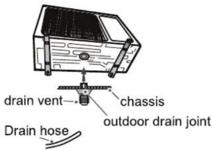
Step Two: Install drain joint (Only for cooling and heating unit)
- Connect the outdoor drain joint into the hole on the chassis, as shown in the picture below.
- Connect the drain hose into the drain vent.
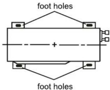
Step Three: Fix outdoor unit
- Place the outdoor unit on the support.
- Fix the foot holes of outdoor unit with bolts.
Installation of Outdoor Unit
Step Four: Connect indoor and outdoor pipes
- Remove the screw on the right handle of outdoor unit and then remove the handle.
- Remove the screw cap of valve and aim the pipe joint at the bellmouth of pipe.
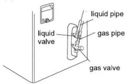
- Pretightening the union nut with hand.
- Tighten the union nut with torque wrench by referring to the sheet below.
| Hex nut diameter | Tightening torque (N·m) |
| Φ6(1/4") | 15~20 |
| Φ9.52(3/8") | 30~40 |
| Φ12(1/2") | 45~55 |
| Φ16(5/8") | 60~65 |
| Φ19(3/4") | 70~75 |
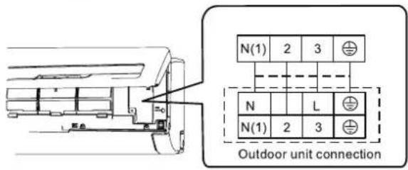
Step Five: Connect Outdoor electric wire
- Remove the wire clip; connect the power connection cord and power cord to the wiring terminal according to the color; fix them with screws.
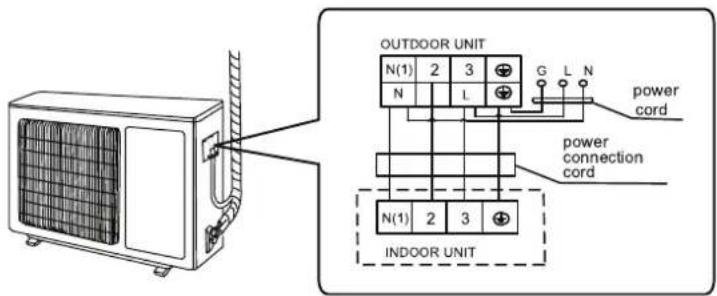
Installation of Outdoor Unit
- Fix the power connection cord and power cord with wire clip.
Note:
- After tighten the screw, pull the power cord and power connection cord slightly to check if they are firm.
- Never cut the power connection cord to prolong or shorten the distance.
Step Six: Neaten the pipes
- The pipes should be placed along the wall, bent reasonably and hidden possibly. Min. semidiameter of bending the pipe is 10cm.
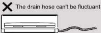
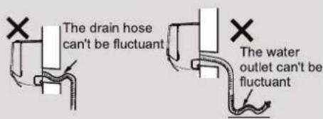
- If the outdoor unit is higher than the wall hole, you must set a U-shaped curve in the pipe before pipe goes into the room, in order to prevent rain from getting into the room.
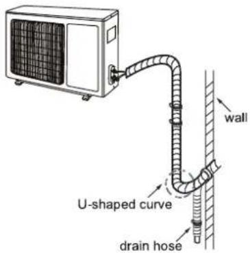
Note:
- The through-wall height of drain hose shouldn't be higher than the outlet pipe hole of indoor unit.
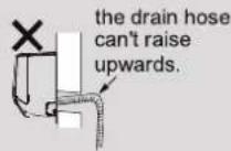
- The water outlet can't be placed in water in order to drain smoothly.
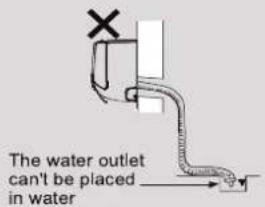
- Slant the drain hose slightly downwards. The drain hose can't be curved, raised and fluctuant, etc.
Vacuum Pumping
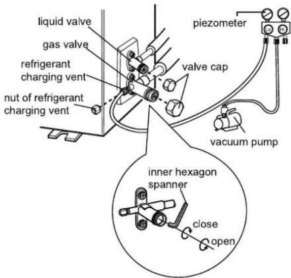
Use vacuum pump
- Remove the valve caps on the liquid valve and gas valve and the nut of refrigerant charging vent.
- Connect the charging hose of piezometer to the refrigerant charging vent of gas valve and then connect the other charging hose to the vacuum pump.
- Open the piezometer completely and operate for 10-15min to check if the pressure of piezometer remains in -0.1MPa.
- Close the vacuum pump and maintain this status for 1-2min to check if the pressure of piezometer remains in -0.1MPa. If the pressure of
- Remove the piezometer, open the valve core of liquid valve and gas valve completely with inner hexagon spanner.
- Tighten the screw caps of valves and refrigerant charging vent.
- Reinstall the handle.
Leakage Detection
- With leakage detector: Check if there is leakage with leakage detector.
- With soap water: If leakage detector is not available, please use soap water for leakage detection. Apply soap water at the suspected position and keep the soap water for more than 3min. If there are air bubbles coming out of this position, there's a leakage.
Check after Installation
- Check according to the following requirement after finishing installation.
| Items to be checked | Possible malfunction |
| Has the unit been installed firmly? | The unit may drop, shake or emit noise. |
| Have you done the refrigerant leakage test? | It may cause insufficient cooling (heating) capacity. |
| Is heat insulation of pipeline sufficient? | It may cause condensation and water dripping. |
| Is water drained well? | It may cause condensation and water dripping. |
| Is the voltage of power supply according to the voltage marked on the nameplate? | It may cause malfunction or damaging the parts. |
| Is electric wiring and pipeline installed correctly? | It may cause malfunction or damaging the parts. |
| Is the unit grounded securely? | It may cause electric leakage. |
| Does the power cord follow the specification? | It may cause malfunction or damaging the parts. |
| Is there any obstruction in the air inlet and outlet? | It may cause insufficient cooling (heating) capacity. |
| The dust and sundries caused during installation are removed? | It may cause malfunction or damaging the parts. |
| The gas valve and liquid valve of connection pipe are open completely? | It may cause insufficient cooling (heating) capacity. |
Test Operation
-
Preparation of test operation
-
The client approves the air conditioner.
-
Specify the important notes for air conditioner to the client.
-
Method of test operation
-
Put through the power, press ON/OFF button on the remote controller to start operation.
- Press MODE button to select AUTO, COOL, DRY, FAN and HEAT to check whether the operation is normal or not.
- If the ambient temperature is lower than 16^(60.8^) , the air conditioner can't start cooling.
Configuration of Connection Pipe
- Standard length of connection pipe
- 5m(16.4ft), 7.5m(24.6ft), 8m(26.24ft).
-
Min. length of connection pipe is 3m(9.84ft).
-
Max. length of connection pipe and max. high difference.
| Cooling capacity | Max length of connection pipe | Max height difference |
| 5000Btu/h (1465W) | 15(49.21ft) | 5(16.4ft) |
| 7000Btu/h (2051W) | 15(49.21ft) | 5(16.4ft) |
| 9000Btu/h (2637W) | 15(49.21ft) | 5(16.4ft) |
| 12000Btu/h (3516W) | 20(65.61ft) | 10(32.8ft) |
| 18000Btu/h (5274W) | 25(82.02ft) | 10(32.8ft) |
| Cooling capacity | Max length of connection pipe | Max height difference |
| 24000Btu/h (7032W) | 25(82.02ft) | 10(32.8ft) |
| 28000Btu/h (8204W) | 30(98.42ft) | 10(32.8ft) |
| 36000Btu/h (10548W) | 30(98.42ft) | 20(65.61ft) |
| 42000Btu/h (12306W) | 30(98.42ft) | 20(65.61ft) |
| 48000Btu/h (14064W) | 30(98.42ft) | 20(65.61ft) |
-
The additional refrigerant oil and refrigerant charging required after prolonging connection pipe
-
After the length of connection pipe is prolonged for 10m(32.8ft) at the basis of standard length, you should add 5ml of refrigerant oil for each additional 5m of connection pipe.
- The calculation method of additional refrigerant charging amount (on the basis of liquid pipe):
Additional refrigerant charging amount = prolonged length of liquid pipe × additional refrigerant charging amount per meter
- When the length of connection pipe is above 5m(16.4ft, add refrigerant according to the prolonged length of liquid pipe. The additional refrigerant charging amount per meter is different according to the diameter of liquid pipe. See the following sheet.
Configuration of Connection Pipe
Additional refrigerant charging amount for R22, R407C, R410A and R134a
| Diameter of connection pipe | Outdoor unit throttle | ||
| Liquid pipe(mm) | Gas pipe(mm) | Cooling only(g/m) | Cooling and heating(g/m) |
| 6(1/4") | 9.52(3/8") or 12(1/2") | 15 | 20 |
| 6(1/4") or 9.52(3/8") | 16(5/8") or 19(3/4") | 15 | 50 |
| 12(1/2") | 19(3/4") or 22.2(1in) | 30 | 120 |
| 16(5/8") | 25.4(9/8") or 31.8(5/4) | 60 | 120 |
| 19(3/4") | - | 250 | 250 |
| 22.2(1in) | - | 350 | 350 |
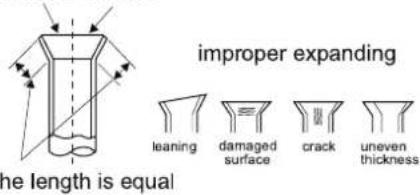
Pipe Expanding Method
Note:
Improper pipe expanding is the main cause of refrigerant leakage. Please expand the pipe according to the following steps:
A: Cut the pipe
- Confirm the pipe length according to the distance of indoor unit and outdoor unit.
- Cut the required pipe with pipe cutter.
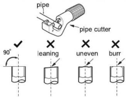
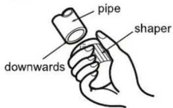
B: Remove the burrs
- Remove the burrs with shaper and prevent the burrs from getting into the pipe.
C: Put on suitable insulating pipe
D: Put on the union nut
- Remove the union nut on the indoor connection pipe and outdoor valve; install the union nut on the pipe.
E: Expand the port
- Expand the port with expander.
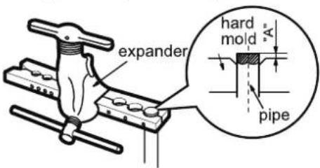
Note:
- "A" is different according to the diameter, please refer to the sheet below:
| Outer diameter (mm) | A(mm) | A(in) | ||
| Max | Min | Max | Min | |
| Φ6-6.35(1/4") | 1.3 | 0.7 | 0.05 | 0.02 |
| Φ9.52(3/8") | 1.6 | 1.0 | 0.06 | 0.04 |
| Φ12-12.7(1/2") | 1.8 | 1.0 | 0.07 | 0.04 |
| Φ15.8-16(5/8") | 2.4 | 2.2 | 0.09 | 0.08 |
F: Inspection
- Check the quality of expanding port. If there is any blemish, expand the port again according to the steps above.
smooth surface

TATUNG
TATUNG Co. of America, Inc.
2850 El Presidio Street, Long Beach CA 90810, U.S.A
TEL:(310)637-2105 FAX:(310)632-3588