UC-6007 - Security Camera Jablotron - Free user manual and instructions
Find the device manual for free UC-6007 Jablotron in PDF.


| Product Type | Security Camera |
| Brand | Joblotron |
| Model | UC-6007 |
| Dimensions | 7.2 x 6.5 x 4.8 cm |
| Weight | 250 g |
| Power Supply | DC 5V/1A via Micro USB |
| Image Sensor | 1/2.7" CMOS |
| Resolution | 1920 x 1080 Full HD |
| Night Vision | Up to 10m with IR LEDs |
| Field of View | 130° diagonal |
| Connectivity | Wi-Fi 2.4GHz IEEE 802.11b/g/n |
| Storage | MicroSD up to 128GB; Cloud (subscription) |
| Motion Detection | Yes, configurable zones and sensitivity |
| Two-Way Audio | Yes, built-in microphone and speaker |
| Weatherproof Rating | IP65 (outdoor use) |
| Operating Temperature | -10°C to 50°C |
| Mounting Type | Wall or ceiling mount included |
| App Support | Joblotron Home (iOS/Android) |
| Warranty | 1 year |
Frequently Asked Questions - UC-6007 Jablotron
User questions about UC-6007 Jablotron
0 question about this device. Answer the ones you know or ask your own.
Ask a new question about this device
Download the instructions for your Security Camera in PDF format for free! Find your manual UC-6007 - Jablotron and take your electronic device back in hand. On this page are published all the documents necessary for the use of your device. UC-6007 by Jablotron.
USER MANUAL UC-6007 Jablotron
The UC-6007/6014 receiver
The UC-6007 is a 7-channel receiver of signals from TP wireless thermostats or from JA-60 wireless detectors (JA-60N, JA-60SP, JA-60SR, JA-60G etc.) and RC-4x remote controls. The receiver has 7 outputs, which can be used to control various devices. LEDs on the receiver's front cover indicate the status of each output channel.
The UC-6014 is 14 channel version. Due to maximal current limits load the pulse switching of the outputs is used. Therefore the UC-6014 should be used only with thermostatic regulators. It should not be used to control any relay semiconductor switch etc.
When used with wireless thermostats, the UC-6007/6014 can efficiently control multi-zone heating and cooling systems. Additionally, a power relay is used as a pump control (the relay is on if any output is triggered).
Installation
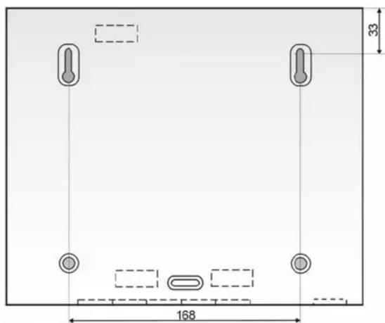
Attach the unit to the desired location with three screws. Route all the cables to the unit before you tighten the case.
Fix the cables firmly inside the box by a sliding strap.
Note: Only a qualified technician can provide installation and servicing. The user is not allowed to open the cover and/or make any modifications.
Terminal description:
AC, AC – power input 24 V AC
L_A, N_A,
PE_A – power supply input for the circulatory pump (use an external fuse for its protection)
L_B, N_B,
PE_B – terminals for the circulatory pump connection (the L-B terminal is triggered if any of the 1-7(14) outputs are switched on)
1-7 - transistor outputs (switchable to ground)
COM – common positive output terminals (24V DC)
The receiver is protected against shorts on the output. If the output is overloaded (the current is greater than 0.4A), then the output is automatically disconnected. A fault is indicated by rapid red flashing of the corresponding LED indicator. The output is under constant monitoring and when the output current decreases below 0.4A the output will be switched on again.
If it is necessary to have more channels, then it is possible to connect another unit via a 2-wire cable. The S/M (slave/master) jumper determines the main receiver. If only one receiver is used, then the jumper must remain in the master position.
Enrollment of transmitters
For each channel of the receiver, a transmitter (thermostat or wireless detector) can be enrolled in the following way:
- Repeatedly press button < or > (left, right arrow) to select the desired channel (the current channel will be indicated by its LED flashing)
- Insert batteries into the transmitter (thermostat or detector). When powered up, the transmitter generates an enrollment signal and its code is stored in the selected receiver channel's memory
- Enrollment of the transmitter is confirmed by the constant lighting of the green LED
Only one transmitter can be enrolled to each channel. A transmitter can be enrolled to multiple channels or other receivers without any restrictions. If you try to enroll a new transmitter to an occupied channel, the new transmitter will be stored and the former one will be deleted.
Deleting a transmitter
To delete an existing transmitter:
- Using buttons < and > select the desired channel (the current channel will be indicated by its LED flashing)
- Press the RES button, the corresponding LED will turn off and the transmitter is deleted.

Indicators 1-7 (1-14)
Indicators on the front housing of the receiver indicate the status of the output channels
| 1 | 2 | 3 | 4 | 5 | 6 | 7 |
| CHANNEL |
| LEDs 1 to 7(14) Meaning | |
| Off Channel is not used (no transmitter is enrolled) | |
| Steady Green Channel has a transmitter enrolled, relay is off | |
| Steady Red Relay is on (activated by the enrolled transmitter) | |
| Flashing Green | Communication with the enrolled transmitter is down (Low battery in transmitter, radio interference etc.) |
| Flashing Red Enrollment mode (to enroll a transmitter) | |
| Flashing Red (rapidly) | Output is overloaded or short-circuited. |
Control channel MODE
The receiver has a special control channel MODE to which a control panel type JA-6x (PgX output) or RC-4x remote controls can be enrolled. This channel can be used for remotely controlling the mode in which the outputs will work.
If no transmitter is enrolled to the MODE channel, then outputs 1-7(14) react in a normal way to signals from their corresponding thermostats.
If the control panel is enrolled and the PgX output is activated (indicator MODE lit red) outputs 1-7(14) react in a normal way to signals from their corresponding thermostats.
If the PgX output is deactivated (indicator MODE lit green), then outputs 1-7(14) ignore signals from thermostats. They only react to anti-frost signals from a thermostat supporting this feature (e.g. TP-31).
Indicator MODE
| Off Channel is | not used - no transmitter is enrolled (receiver reacts to standard signals from thermostats) |
| Steady Green | Transmitter is enrolled – channel MODE is deactivated, outputs 1-7(14) only react to the anti-frost signals from thermostats |
| Steady Red | Transmitter is enrolled – channel MODE is activated, outputs 1-7(14) react to standard signals from thermostats |
| Flashing Green | Communication with the enrolled transmitter is down (Low battery in transmitter, radio interference etc.) |
Use and Maintenance
All enrolled transmitters (thermostats and detectors) transmit regular check signals. If the receiver does not receive the signal of an enrolled transmitter for a certain period, it will indicate that communication with this item is down (flashing green LED) and the corresponding output will turn off.
One reason for the lost connection can be low batteries in the transmitter. The average lifetime of a transmitter's batteries is about 1 year. Each transmitter checks its battery conditions and signals in advance if the batteries are reaching a critically low state (see the transmitter manual for details).
Another reason for possible connection failure can be radio signal interference in the operational band of the receiver. In such a case the receiver will usually indicate loss of communication with a multiple number of transmitters. In this situation, check if there is any non-approved or faulty radio-communicating device within the range of the receiver.
Outputs which have not been activated for 7 days will switch on for 5 minutes to protect connected devices, especially pumps which can be damaged if they are not used for a long time.
Warning: the manufacturer is not responsible for any damage caused by improper installation or any non-suitable use of this product.
Specification
Power supply: 230 V AC, 50Hz, protection class II
Consumption: 0.02 A stand-by; 0.2 A max.
Max. relay output load: 10 A / 230V
Voltage of outputs 1-7(14) and COM: 24V DC
Max. load of outputs 1-7(14): max. 0.4 A per single output and 1.7A
total for all outputs
Radio frequency:
Working range with JA-60 100 m (open area)
Working range with RC 30 m (open area)
Dimensions: 258 x 214 x 77
Radio characteristics: ETSI EN 300220
EMC: EN 50130-4, EN 55022
Safety: EN 60950
Working temperature: -10 to +40 °C
Can be operated according to ERC REC 70-03
CE
Jablotron Ltd. hereby declares that the UC-6007/6014 is in compliance with the essential requirements and other relevant provisions of Directive 1999/5/EC. The original of the conformity assessment can be found on website www.jablotron.com -Technical support section.

Note: Although this product does not contain any harmful materials we suggest you return the product to the dealer or directly to the producer after use.

natural_image
Simple geometric diagram with a horizontal rectangle and dimension label (258), no text or symbols present.
Dimensions

JABLOTRON
Pod Skalkou 33
466 01 Jablonec nad Nisou
Czech Republic
Tel.: +420 483 559 999
fax: +420 483 559 993
Brand : Jablotron
Model : UC-6007
Category : Security Camera