
661.624530 - Air conditioner KENMORE - Free user manual and instructions
Find the device manual for free 661.624530 KENMORE in PDF.

| Product Type | Convertible Evaporative Air Cooler (Down/Front Outlet) |
| Brand | Kenmore |
| Model Number | 661.624530 |
| Cabinet Dimensions (H x W x D) | 33 3/4 in x 33 3/4 in x 37 1/2 in |
| Air Output Opening (H x W) | 19 3/4 in x 19 3/4 in |
| Operating Weight (with water) | 235 lbs |
| Air Output Rating | 5200 CFM |
| Outlet Configuration | Convertible between down discharge and side discharge |
| Cooling Method | Evaporative cooling using water-saturated pads |
| Water Supply | Float valve with automatic water level control, optional bleed-off kit |
| Reservoirs | Two removable water trays connected by crossover tube |
| Pads | Replacement pad part #32-6294 (Sears) |
| Blower Motor | Includes belt-driven blower, adjustable motor pulley for CFM tuning |
| Pad Motors | Two motors rotate pads through water |
| Speed Control | 5-position wall switch (Sears #32-6251): Off, Low Vent, High Vent, Low Cool, High Cool |
| Electrical Requirements | 115V, 60Hz, typical circuit; must comply with local codes |
| Warranty | 1 year full; 5 years limited on cabinet and blower housing |
| Installation | Roof or pad mount; duct required; roof stand kit #32-6257 recommended |
| Lubrication | Annual oiling of blower shaft bearings and pad motor end bearings with SAE 20 non-detergent oil |
| Pulley Adjustment | Motor pulley pitch adjustable to match duct resistance, checked with ammeter |
| Belt Tension | Adjustable by moving motor bracket; 1/2 inch deflection at center |
| Minimum Window/Vent Opening | 12 sq ft total for proper airflow |
| Drain | Two overflow pipes with drain fittings; do not drain on roof |
| Safety | Must disconnect power before service; do not install in storm; use mesh guard on outlet |
Frequently Asked Questions - 661.624530 KENMORE
User questions about 661.624530 KENMORE
0 question about this device. Answer the ones you know or ask your own.
Ask a new question about this device
Download the instructions for your Air conditioner in PDF format for free! Find your manual 661.624530 - KENMORE and take your electronic device back in hand. On this page are published all the documents necessary for the use of your device. 661.624530 by KENMORE.
USER MANUAL 661.624530 KENMORE
THIS INSTRUCTION MANUAL

natural_image
Illustration of a server rack unit with multiple drive bays and ventilation grilles (no text or labels visible)Kenmore
CONVERTIBLE
DOWN/FRONT OUTLET
EVAPORATIVE AIR COOLER
- Installation
Operation - Repair Parts
CONTENTS INSTALLATION
| Tools and Supplies You Need | 3 |
| Safety Rules | 3 |
| Data | 3 |
| Locating Your Cooler | 4 |
| Converting to Side Outlet | 5 |
| Mounting Cooler | 6 |
| Electrical Connections | 7 |
| Final Assembly and Adjustment | 8 |
| Startup Check List | 9 |
COOLER USE
| Cooling Your Home | 10 |
| Cooler Care | |
| Spring, Summer and Fall Care | 11 |
| Taking Off and Putting On Grills | 11 |
| Taking Off Pad | 12 |
| Cleaning | 12 |
| Putting on Pad | 13 |
| Oiling | 13 |
| Blower Belt Adjustment | 13 |
| REPAIR PARTS | 14 |
NEED ADVICE? MISSING PARTS? - CALL MANUFACTURER FIRST:
Just dial this toll free number 1-800-643-2742 to get facts fast:
Call Monday through Friday 8:00 A.M. to 5:00 P.M. - Central Time
Our experienced Hotline Service Representative can:
• Answer installation questions.
- Provide prompt shipment of missing parts.
YOUR SATISFACTION IS OUR NUMBER ONE PRIORITY
Reminder: The person you will be talking to is Not a SEARS store employee and cannot handle exchanges, arrange service calls etc.. This must be handled through your Sears Store or Catalog Order Department. This toll-free number is for technical assistance only.
FULL ONE YEAR WARRANTY ON SEARS EVAPORATIVE COOLER
One year from the date of purchase when this Kenmore Roto-Belt evaporative air cooler is installed and maintained according to our instructions, Sears will repair defects in material or workmanship free of charge
FIVE YEAR LIMITED WARRANTY
All Sears Kenmore Roto-Belt cooler cabinets and blower housings are warranted against rusting out and becoming inoperative after one year and through five (5) years from the date of purchase. Sears Roto-Belt cooler water reservoirs and louvers are warranted also against leaking and deterioration due to water corrosion for the same period of time. You pay for labor
WARRANTY SERVICE IS AVAILABLE BY SIMPLY CONTACTING THE NEAREST SEARS SERVICE CENTER THROUGHOUT THE UNITED STATES
This warranty gives you specific legal rights, and you may also have other rights which vary from state to state
SEARS, ROEBUCK AND CO., DEPT. 698/731A, SEARS TOWER, CHICAGO, IL. 60684
Note: Replacement of filter pads is normal maintenance and is not covered in the warranty
SEARS INSTALLATION POLICY
All installation labor arranged by Sears shall be performed in a nea' workmanship manner in accordance with generally accepted trade practices. Further, all installations shall comply with all local laws, codes, regulations and ordinances. The customer shall also be protected, during installation, by insurance relating to property damage. Workmen's Compensation and Public Liability.
SEARS INSTALLATION WARRANTY
In addition to any warranty extended to you on the Sears merchandise involved, which warranty becomes effective the date the merchandise is installed, should the workmanship of any Sears arranged installation prove faulty within one year, Sears will, upon notice from you, cause such faults to be corrected at no atti-tional cost to you
TOOLS AND SUPPLIES YOU WILL NEED
• Pliers
- Screwdrivers
- Adjustable Wrenches
- Tubing Cutter
- 5/32 Hex Key Wrench
- Electric Drill
- Drill Bits
- Hammer
• Duct Caulking
• 10 Sheet Metal Screws
• Wiring Supplies, as Required by Local Electrical Code
- Level
RULES FOR YOUR SAFETY
- WARNING
TO AVOID FIRE, SHOCK, AND SERIOUS PERSONAL INJURY FOLLOW THESE INSTRUCTIONS
- The installation must conform to local codes and utility standards. Use the National Electric Code if a local code does not exist.
- Disconnect the electric power EVERY TIME you work on your cooler. When your hands are inside the cooler you risk injury if the cooler is accidentally turned on from inside the home.
- If you mount the cooler on your home roof remember these safety tips:
• Duct, As Required (a local sheetmetal shop can supply ducting)
• Equipment Suitable for Installing Duct Through House Wall or Roof
- Water Connection. Use Kit # 62527, #62528 or #62522 Saddle Valve. See page 8 (Connect Water line) for further information explaining the different water hook ups.
- Roof Stand Kit (if cooler is roof mounted)
Cooler 661.623920 use 32-6256 kit
Cooler 661.624420 use 32-6256 kit
Cooler 661.624530 use 32-6257 kit
• Cooler 661.624630 use 32-6258 kit
• Cooler 661.624670 use 32-6258 kit
• 32-6251 (5 position) Wall Switch for Either New or Existing Pump Type Cooler Wiring.
- Never install or service a cooler during a storm or high wind conditions. You could be injured or lose or damage parts.
- Never wear shoes with slick soles when you work on a roof. You may slip when you least expect it.
- Never drain water onto a roof. Water residue may cause you to slip or may stain your roof. Use a drain hose to run the drain water to a rain gutter or to a drain.
- To avoid injury never use the cooler without connecting it to a house duct system or without a sturdy mesh guard over the outlet.
DATA
| Model No. | Cabinet Dimensions (Inches) | Air Output Opening (Inches) | Operating Lbs. Weight (with water) | |||
| Height | Width | Depth | Height | Width | ||
| 661 623920 | 2934 | 2934 | 3518 | 1734 | 1734 | 195 |
| 661 624420 | 2934 | 2934 | 3518 | 1734 | 1734 | 190 |
| 661 624530 | 3334 | 3334 | 3712 | 1934 | 1934 | 235 |
| 661 624630 | 3634 | 3614 | 42^13/16 | 1934 | 1934 | 285 |
| 661 624670 | 3634 | 3614 | 42^13/16 | 1934 | 1934 | 289 |
OUTPUT RATINGS
(Cubic Feet Per minute)
| Model No. | Industry Rating |
| 661 623920 | 4500cfm |
| 661 624420 | 4000cfm |
| 661 624530 | 5200cfm |
| 661 624630 | 6600cfm |
| 661 624670 | 7200cfm |
SEARS EVAPORATIVE PAD USAGE
| Model No. | Sears Pad Number |
| 661 623920 | 32-6293 |
| 661 624420 | 32-6293 |
| 661 624520 | 32-6294 |
| 661 624620 | 32-6295 |
| 661 624670 | 32-6295 |

LOCATING YOUR COOLER
Your cooler has been shipped ready for installation in a down discharge position. It can easily be changed to side discharge. The cooler must be securely fastened to a frame or pad mount. A roof kit is available from Sears.
A duct must be attached to the cooler outlet. The duct must be the same size as the cooler outlet. Sudden duct size changes will decrease the output of your cooler.
The cooler installation must comply with local codes. If you are not fully qualified to install a cooler, get professional help.
Figure 1 shows locations for your cooler. Be sure the intake louvers are clear of obstructions and are accessible for removal. Do not locate the cooler near vent pipes, chimneys, or exhaust where odors or fumes may be drawn into the house. The two drain holes on the cooler bottom must be clear to allow overflow or drain access.

WIRING BOX (FIGURE 2)
The wiring box is inside the cooler cabinet. The electrical supply must be connected to the cooler power leads inside the box after the cooler in installed. The wiring box is factory installed for coolers used in the down air outlet position.
IF YOU INSTALL THE COOLER IN THE SIDE AIR DISCHARGE POSITION THE WIRING BOX MUST BE MOVED. SEE PAGE 5.
SHUT OFF POWER AT THE ELECTRICAL SERVICE BOX BEFORE STARTING WIRING.
YOU MAY WANT TO CONVERT YOUR COOLER TO SIDE DISCHARGE (Figure 3)
CONVERTING COOLER TO SIDE AIR DISCHARGE (FIG.4)
① Remove both louvers and set them where they will not fall. See pg. 11, "Taking Off Louver"
② Remove four grille clips on side opposite motor.
③ Remove a reservoir by pushing the water crossover tube from the grommet and lifting out the reservoir.
④ Remove the second reservoir as above.
⑤ Remove the screw that holds the wiring box.
⑥ Remove 18 inch diameter and 78 inch diameter knockouts.
⑦ Remove two plastic plugs.
⑧ Loosen screw holding pad motor receptacle bracket, slide bracket up and detach from cabinet flange. Repeat on other side.
- Turn cooler to side outlet position. (Figure 5)
REASSEMBLY AS SIDE OUTLET COOLER (Fig 5)
① Move wiring box to new location.
② Secure wiring box with screw removed at disassembly.
③ Install four louver clips removed at disassembly.
④ Install two receptacle brackets removed at disassembly.
⑤ Install two plastic plugs removed at disassembly
- Assembly reservoirs, crossover tube and louvers after the cooler is installed in location. Use soap or detergent to lubricate crossover tube before inserting into grommet. DO NOT USE OIL.
ROUTE WIRES INSIDE OF PANEL
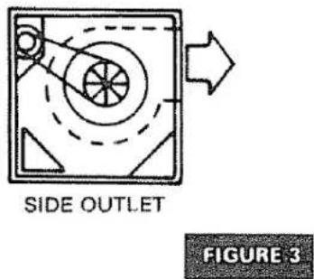

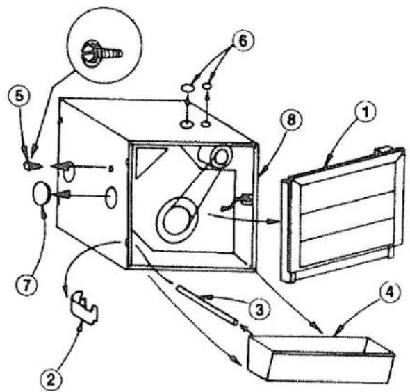
FIGURE 4
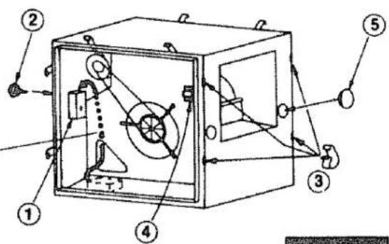
FIGURE 5
LIFTING COOLER
CAUTION: DO NOT LIFT ON THE LOUVERS. REMOVE THE LOUVERS BEFORE LIFTING. DO NOT LIFT ON THE CENTER OF THE CABINET FLANGES
Lift at cabinet corners
The cooler may be lifted by putting a bar or strap through the panel hole and lifting by means of the bar or strap (Fig 6)

natural_image
Simple line drawing of a box with internal components and arrows, no text or symbols presentFIGURE 6
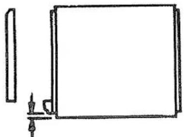
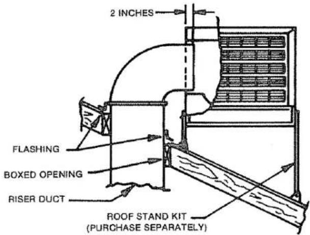
MOUNTING COOLER (Fig. 7)
- Prepare duct to fit model used. See outlet size specifications on page 3.
- Cut opening in roof or wall to fit duct opening on cooler and box in opening.
- Install duct and secure to boxed-in opening frame. Allow the two inches to fit into cooler outlet. Allow duct length for cooler bottom to be 4 inches above roof at closet point.
- Install flashing on roof or wall to prevent water entry.
- Measure cooler and lay out mount location.
NOTE: THE BOTTOM EDGE NEAREST THE AIR OUTLET MUST FACE UP THE ROOF.
- Mount cooler on stand or pad. Cooler must be level front to back and left to right. Sears roof stand kits are available.
- Be sure to securely fasten four corners of cooler to stand or pad.
- Caulk duct to the cooler. Caulk the flashing.
natural_image
Simple line drawing of a rectangular frame with a vertical bar and a small protrusion at the bottom (no text or symbols)^2/_4 MAXIMUM HEIGHT FOR STAND SIDE EDGE TO ALLOW RESERVOIR CLEARANCE

ABOUT 1 THICK
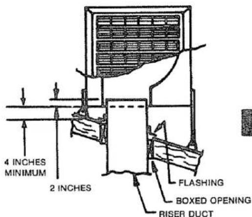
FIGURE 7
ELECTRICAL CONNECTIONS
The wiring must comply with local codes. If you are not familiar with the codes or wiring practices, get professional help.
NEW INSTALLATIONS OR COOLER CHANGEOUT INSTALLATIONS
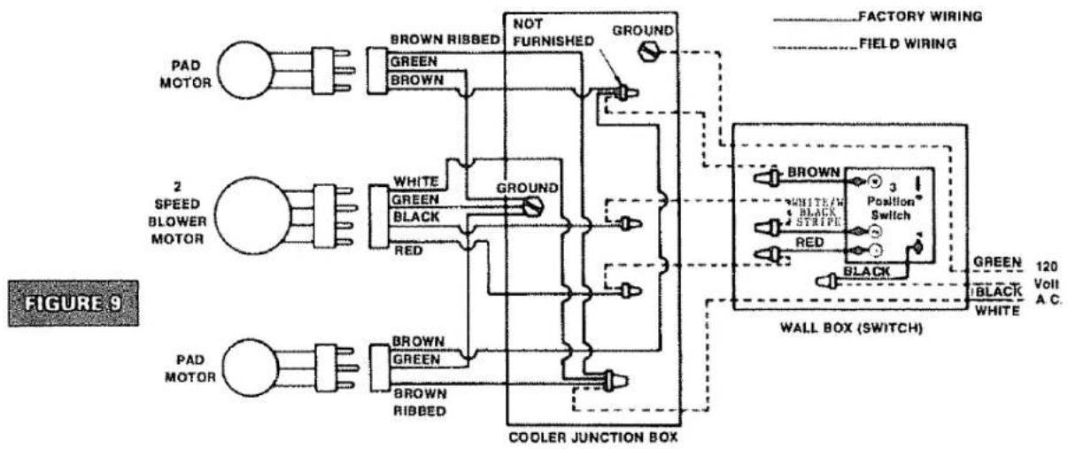
Use Sears 32 6251 Switch which is suitable for either new installations or existing installations. When installing a cooler or existing installation; five wires must go to the cooler including grounding connector. There are two cool positions and two vent positions. Figure 9 shows how to wire the 32.6251 switch.
Use only a Sears 32-6251 wall mounted switch. This new cooler does not require prewetting the pads before starting cooling and does not have a pump. Existing switches with "pump only" position are not usable.
CAUTION: SHUT OFF THE ELECTRIC POWER AT THE FUSE BOX BEFORE BEGINNING THE WIRING.
WARNING: TO REDUCE THE RISK OF FIRE OR ELECTRIC SHOCK, DO NOT USE THIS FAN WITH ANY SOLID-STATE SPEED CONTROL DEVICE
FLOAT VALVE INSTALLATION INSTRUCTIONS
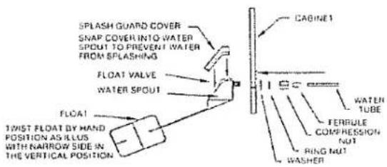
It is of the Utmost Importance that the Float Valve Splash Guard and Splash Guard Cover be installed exactly as described in the illustration below
1) The Float Valve-Must be installed with the narrow side of the float in the vertical position. If not installed this way the float will hang up and cause the reservoir drain pipes to overflow
2) The water Spout and Water Spout Cover are provided to prevent water from spurting and splashing outside of the reservoirs. Snap in the Splash Guard Cover as illustrated below
FINAL ASSEMBLY AND ADJUSTMENT
PUT FLOAT VALVE IN COOLER
Put the float valve through the spout hole and cabinet hole Tighten the ring nut. Be sure the float moves straight up and down. TURN THE FLOAT UNTIL A NARROW SIDE IS UP. Snap the Splash Guard Cover into the Water Spout as shown. The Water Spout and Splash Guard Cover are provided to prevent water from "spurting" and splashing outside the Water Reservoir.
CONNECT WATER LINE
For outdoor Hook Up, use #62527 Copper Hook Up Kit or #62528 Plastic Hook Up Kit. Both kits contain all necessary fittings to connect water to cooler. For indoor kit use copper tubing and #62522 self piercing saddle valve.
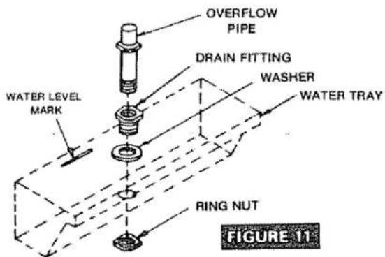
PUT IN OVERFLOW PIPE (Fig. 11)
- Push the drain fitting through the washer and water tray hole. Tighten the ring nut. Screw the overflow pipe into the drain fitting. Repeat for the second tray.
NOTE: INSTALL DRAIN FITTING INVERTED IF COOLER IS MOUNTED ON A PAD. CUT OFF THE OVERFLOW PIPE TOP FLUSH WITH THE HEXAGONAL RING.
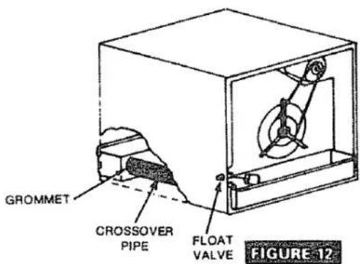
- Put in the float valve side tray first. The crossover tube and grommet MUST be on the float valve side. (Fig 12).
- Push the crossover tube into the grommet. Use soap or detergent as a lubricant. DO NOT USE OIL.
- Put the second water tray in place. Push the crossover tube into the grommet.
ADJUST WATER LEVEL
- Turn on the water. Check the water level when the valve shuts off. If the water level is above the tray water level mark bend the float rod down. If the level is too low, bend the rod up.
NOTE: CHECK THE CROSSOVER PIPE GROMMETS AND ALL CONNECTIONS FOR LEAKS.
PUT LOUVERS ON COOLER
See page 11

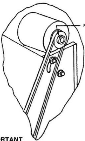
MOTOR PULLEY ADJUSTMENT (Figure 13)
NOTE: ALL DUCT CONNECTED COOLERS MUST BE ADJUSTED
Long or small air ducts have excessive air resistance which decreases air output and motor amperage. You may compensate for this by adjusting the motor pulley. Use-a clamp type ammeter to check the motor amperage.
- Check amperage at the white lead in the wiring box.
- If the amperage is less than the motor nameplate amperage, loosen the pulley pitch adjustment screw, turn the pulley 12 turn clockwise, tighten the screw and recheck the amperes. Repeat as necessary to bring the amperage to the nameplate rating.
- If the amperage is too high, turn the pulley counter - clockwise as required.
- Adjust the belt tension as required. (See page 13).
natural_image
Technical line drawing of a mechanical device with labeled component 'P' and 'RTANT' (no readable text or symbols beyond label)PITCH ADJUSTMENT
SCREW
FIGURE 13
IMPORTANT
NOTE: When checking amperage with the ammeter; all louvers must be in place in the cooler; otherwise incorrect setting of the drive pulley will occur
STARTUP INSPECTION
Before starting the cooler, make sure all installations and adjustments are correct. Be sure that:
• Cooler is level and duct is sealed
• Cabinet is securely fastened to the mount.
• Cooler is grounded. Electrical connections are secure.
- Blower wheel does not rub against housing
• Water supply is turned on
• Water line is connected securely and fittings and crossover tube grommets do not leak
- Float is adjusted for proper water level.
- Pulley alignment is OK Belt tension is OK (See page 13)
- Pads are correctly installed (See page 13)
- Blower and both pad motors are plugged into receptacles.
- All louver clips are snapped tight
STARTUP CHECK LIST
To check out the installation follow this startup procedure. Set the control to each position and check operation per the following chart. Be sure to open windows or vents.
OPERATION WITH SEARS SWITCH 32-6251
(Five Position)
| Switch | Blower Motor | Pad Motors |
| Off | Off | Off |
| Low Vent | Low | Off |
| High Vent | High | Off |
| Low Cool | Low | On |
| High Cool | High | On |
Your cooler evaporates water to cool air. Evaporative air cooling is the same natural cooling that happens when a breeze springs up after a summer shower. You feel cool because the rain water evaporates and carries away heat.
Your new cooler has a motor (1) driven blower (2) which draws outside air through pads (3) which are turned by drive motors (4). The pads turn through water in trays (5) filled by the water float valve (6) and water crossover pipe (7). Air passes through the pads, is cooled by water evaporation, and is sent into your home. (Figure 14)
You may also run the cooler in "Vent" when you want fresh air and no cooling.
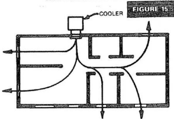
Relative humidity affects the cooling capacity of any cooler. See chart to determine the maximum amount of cooling possible at your outside temperature and outside humidity (Figure 15)
COOLING YOUR HOME
Your cooler and window or vents are the two parts of your air cooling system. Outside air is filtered and cooled, goes through your home, and carries away heat and household odors. You control the air cooling flow to your rooms by opening doors, windows, or vents. (Figure 16)
You must have window, door, or vent openings to let air out when the cooler runs. The total opening areas you need are shown below:
| MODEL | TOTAL OPENING AREA |
| 661.623920 | 11 Square feet minimum |
| 661.624420 | 10 Square feet minimum |
| 661.624530 | 12 Square feet minimum |
| 661.624630 | 14 Square feet minimum |
| 661.624670 | 16 Square feet minimum |

FIGURE 14
LOWEST POSSIBLE OUTPUT TEMPERATURE:
TYPICAL AIR FLOW
FIGURE 16
CAUTION: ALWAYS UNPLUG YOUR COOLER BEFORE YOU WORK ON IT YOU COULD BE HURT IF THE COOLER IS TURNED ON WHEN YOUR HANDS ARE INSIDE THE COOLER
SPRING CARE: Clean your cooler (See page 12)
Oil your cooler. (See page 13)
Put a new pad in if the old pad is plugged with dirt or water hardness. (See pages 12 and 13).
Check belt tightness (See page 13)
SUMMER CARE: Drain and clean the cooler every two months if your water is hard or the air is dusty
You may prolong pad life in many hard water areas if you drain the water tray every two to three weeks. (See page 12, Preventing mineral build-up).
FALL CARE: Drain the cooler and water line to prevent freezing damage. (See page 12)
Clean the cooler. (See page 12).
Cover the cooler
Sears has covers to fit your cooler.
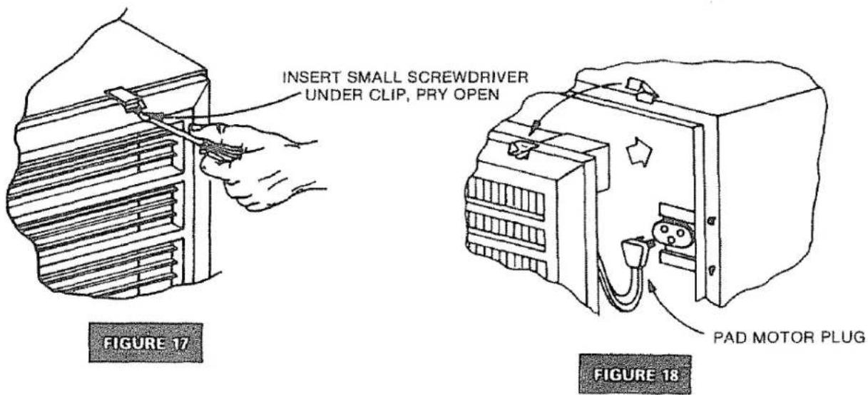
TAKING OFF LOUVER (FIGURE 17)
1 Unsnap the six louver clips Use a small screwdriver
2 Tilt out the louver at the top Unplug the pad motor plug.
3 Take off the louver Set it where it will not fall
PUTTING ON LOUVER (Figure 18)
1 Put the louver bottom into water tray
2 Plug in the pad motor
3 Close the louver Snap the six clips onto the louver
TAKING OFF PAD (Fig. 19)
- Lift up the small roller ends to unsnap the two center rollers. Pull out the two small rollers.
- Pull out and turn the top roller bearing arm to line up the slot.
- Lift edge of pad from under the guide and pull out the top roll end.
- Take out the pad and bottom roller which will slide out of the bottom slots.
CLEANING YOUR COOLER (FIG. 20) HELPS PREVENT MINERAL BUILD-UP
WARNING: NEVER WASH YOUR COOLER INTERIOR WITH A GARDEN HOSE. WATER MAY HARM THE MOTORS OR GET INTO YOUR HOUSE.
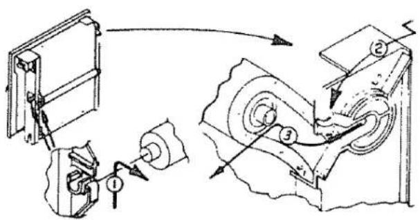
FIGURE 19
- DISCONNECT THE ELECTRIC POWER AT THE FUSE BOX.
- Remove the Louvers. (See page 11)
- Connect a garden hose to a water tray drain fitting. Unscrew and remove the overflow pipe to drain the tray
- Automatic cycling. BLEED—OFF KIT available (Sears 32-62562)
NEVER DRAIN WATER ONTO A ROOF. WATER RESIDUE MAY CAUSE YOU TO SLIP OR MAY STAIN YOUR ROOF. USE A DRAIN HOSE TO RUN WATER TO A RAIN GUTTER OR TO A DRAIN.
- Drain the other tray
- Take off the pads if they are dirty or clogged
- Use a sponge and mild detergent to wash the dirt or scale from the trays and grilles. DO NOT GET WATER ON THE PAD MOTORS.
- If the pads are clogged with hard water deposits and dirt, replace the pads. See page 13
- Put the overflow pipes and grilles in place (See page 11)
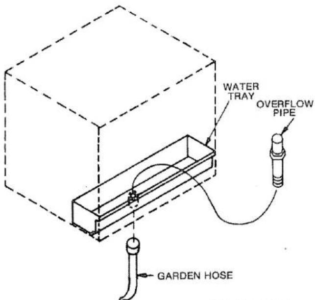
FIGURE 20
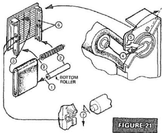
PUTTING ON NEW PAD (Fig. 21)
THE PADS NEED NO PREWETTING
① Put the lower roller in pad.
② Fit the lower roller into the bottom slots in the frame.
③ Push the top roller through the pad Fit the roll end over the pad motor shaft drive block.
④ Push the top roller end into the bearing
⑤ Turn the bearing arm to hold the roller.
⑥ TUCK THE PAD EDGES UNDER THE 2 GUIDES ON EACH SIDE.
⑦ Put the two small center rollers in place. Snap the ends into the holders. (See lubrication instructions below)
OILING (Fig.22)
Use SAE 20 Non-detergent motor oil once per year.
1 Fill the two blower shaft bearing cups Ⓐ
2 Put two or three drops in the two oil fill tubes on the blower motor. (Motors without oil fill tubes have lifetime lubrication).
3 Put two or three drops in the end bearing on each pad motor ©
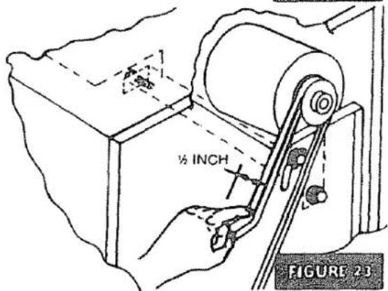
BLOWER BELT ADJUSTMENT (Fig. 23)
CAUTION: DO NOT ADJUST BELT TENSION BY CHANGING THE DIAMETER OF THE MOTOR PULLEY. ADJUST BELT TENSION ONLY BY MOVING THE MOTOR BRACKET.
- If you can easily move the belt over 1 inch. it needs adjustment.
2 To adjust belt tension, loosen the three motor mount bolts. - Push the motor to tighten the belt until belt moves about 12 inch with finger force.
- Tighten the three motor mount bolts
SEARS REPLACEMENT PADS
| MODEL NUMBER | SEARS PAD NUMBER |
| 661.623920 | 42-6293 |
| 661.624420 | 42-6293 |
| 661.624530 | 42-6294 |
| 661.624630 | 42-6295 |
| 661.624670 | 42-6295 |

KENMORE CONVERTIBLE DOWN/FRONT OUTLET EVAPORATIVE AIR COOLER. MODEL NOS. 661.623920, 661.624420, 661.624530, 661.624630, 661.624670
KENMORE CONVERTIBLE DOWN/FRONT OUTLET EVAPORATIVE AIR COOLER MODEL NOS. 661.623920, 661.624420 661-624530 ,661.624630, 661.624670
NOTICE: Order by PART NUMBER, not by Key Number Refer to the back cover of this manual for parts ordering information
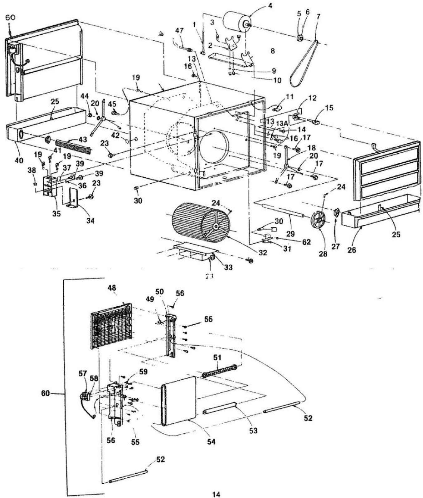
| KEY NO | PART NUMBERS FOR MODEL NUMBERS | DESCRIPTION | ||||
| 661.623920 | 661.624420 | 661.624530 | 661.624630 | 661.624670 | ||
| 1 | 30439 | 30439 | 30439 | 30439 | 30439 | Motor Plug |
| 2 | 50255 | 50255 | 50255 | 50255 | 50255 | Motor Tail Mount |
| 3 | STD523107 | STD523107 | STD523107 | STD523107 | STD523107 | Machine Screw 5/16 - 18 X 3/4 |
| 4 | 32-61074 | 32-61073 | 32-61074 | 32-61075 | 581191 | Motor |
| 5 | 30315 | 30315 | 30315 | 30315 | 583054 | Pulley - includes Key 6 |
| 6 | STD503102 | STD503102 | STD503102 | STD503102 | STD503102 | Set Screw 5/16 - 18 X .25 Hex Socket, Cup Point |
| 7 | STD304550 | STD304580 | STD304640 | 30557 | 30557 | V-Belt |
| 8 | 30305-00 | 30305-00 | 30304-00 | 30304-00 | 30304-00 | Motor Mount |
| 9 | STD551131 | STD551131 | STD551131 | STD551131 | STD551131 | Lock Washer 5/16 Helical Spring |
| 10 | STD541031 | STD541031 | STD541031 | STD541031 | STD541031 | Hex Nut 5/16 -18 |
| 11 | 30105 | 30105 | 30105 | 30105 | 30105 | Clip |
| 12 | 30311-00 | 30311-00 | 30311-00 | 30311-00 | 30311-00 | Receptacle Mound |
| 13 | STD551231 | STD551231 | STD551231 | STD551231 | STD551231 | Lock Washer - 5/16 internal tooth |
| 13A | 50294 | 50294 | 50294 | 50294 | 50294 | Lock Washer |
| 14 | STD610803 | STD610803 | STD610803 | STD610803 | STD610803 | Screw # 8 - 18 X 3/8 Phillips, Type AB |
| 15 | 30432 | 30432 | 30432 | 30432 | 30432 | Pad Motor Connector |
| 16 | 30551 | 30551 | 30551 | 30551 | 30551 | Machine Screw 5/16 - 18 x 3/8 |
| 17 | 08133 | 08133 | 08133 | 08133 | 08133 | Screw 1/4 -14 x 3/8,Type B |
| 18 | V30289 | V30289 | V30288 | V30288 | V30288 | Bearing Mount |
| 19 | 14864 | 14864 | 14864 | 14864 | 14864 | Bushing |
| 20 | 501241 | 501241 | 501241 | 501241 | 501241 | Thrust Washer |
| 23 | 30686 | 30686 | 30686 | 30686 | 30686 | Screw #8 -18 x 1/2, Type B |
| 24 | STD503105 | STD503105 | STD603105 | STD503105 | STD503105 | Set Screw 5/16 - 18 Socket |
| 25 | 31086 | 31086 | 31086 | 31086 | 31086 | Overflow Drain |
| 26 | 32019-10 | 32019-10 | 32025-10 | 32031-10 | 32031-10 | Reservoir |
| 27 | 31984 | 31984 | 31984 | 31984 | 31984 | Grommet |
| 28 | 50462 | 30314 | 30314 | 30314 | 30314 | Pulley-includes Key 24 |
| 29 | 30238-02 | 30238-02 | 30238-01 | 30238-01 | 30238-01 | Shaft |
| 30 | 30482 | 30482 | 30482 | 30482 | 30482 | Float and Valve |
| STD575026 | STD575026 | STD575026 | STD575026 | STD575026 | Ferrule | |
| STD575025 | STD575025 | STD575025 | STD575025 | STD575025 | Compression Nut | |
| 31 | 30418-01 | 30418-01 | 30418-01 | 30418-01 | 30418-01 | Water Shield |
| 32 | 30322 | 30322 | 30323 | 30323 | 30323 | Blower Wheel |
| 33 | 30177 | 30177 | 30148 | 30148 | 30167 | Baffle |
| 34 | 30205 | 30205 | 30205 | 30205 | 30205 | Junction Box Cover |
| 35 | 30202 | 30202 | 30202 | 30202 | 30202 | Junction Box |
| 36 | 27835 | 27835 | 27835 | 27835 | 27835 | Cupped Washer |
| 37 | 14982 | 14982 | 14982 | 14982 | 14982 | Lock Washer #8 Star |
| 38 | 29816 | 29816 | 29816 | 29816 | 29816 | Bushing |
| 39 | 30585 | 30585 | 30585 | 30585 | 30585 | Screw #8 - 32 x 7/16, Type T, Green |
| 40 | 32019-20 | 32019-20 | 32025-20 | 32031-20 | 32031-20 | Reservoir |
| 41 | 30552 | 30552 | 30552 | 30552 | 30552 | Bushing |
| 42 | 29996 | 29996 | 29996 | 29996 | 29996 | Plug |
| 43 | 31985-03 | 31985-03 | 31985-02 | 31985-02 | 31985-02 | Tube |
WHEN ORDERING REPAIR PARTS ALWAYS GIVE THE FOLLOWING INFORMATION:
- PART NUMBER 3. MODEL NUMBER
- PART DESCRIPTION 4. NAME OF ITEM
If the parts you need are not stocked locally, your order will be electronically transmitted to a Sears Repair Parts Disbritution Center for handling.
The Model Number of your cooler will be found on the back side of your cooler
KENMORE CONVERTIBLE DOWN/FRONT OUTLET EVAPORATIVE AIR COOLER MODEL NOS. 661.623920, 661.624420 661-624530 ,661.624630, 661.624670
| Key No. | PART NUMBERS FOR MODEL NUMBERS | DESCRIPTION | ||||
| 661.623920 | 661.624420 | 661.624530 | 661.624630 | 661.624670 | ||
| 44 | 501243 | 501243 | 501243 | 501243 | 501243 | Collar |
| 45 | 30433 | 30433 | 30433 | 30432 | 30432 | Pad Motor Connector |
| 47 | 30878 | 30878 | 30440 | 30441 | 30441 | Motor Connector |
| 48 | 30214-01 | 30214-01 | 30254-01 | 29738-01 | 29738-01 | Louver |
| 49 | 31047 | 31047 | 31047 | 31047 | 31047 | Bearing |
| 50 | 30206-01 | 30206-01 | 30250-01 | 29817-01 | 29817-01 | Side Support |
| 51 | 30224-01 | 30224-01 | 30242-01 | 29861-01 | 29861-01 | Top Roller |
| 52 | 30211 | 30211 | 30235 | 30119 | 30119 | Roller → |
| 53 | 30212 | 30212 | 30237 | 30127 | 30127 | Bottom Roller |
| 54 | 32-6293 | 32-6293 | 32-6294 | 32-6295 | 32-6295 | Evaporator Pad |
| 55 | 30465 | 30465 | 30465 | 30465 | 30465 | Screw #10 16 x % |
| 56 | 30233-01 | 30233-01 | 30256-01 | 29815-01 | 29815-01 | Motor Side Support |
| 57 | V30336 | V30336 | V30336 | V30336 | 00061 | Pad Motor |
| 58 | 29862 | 29862 | 29862 | 29862 | 29862 | Roller Drive |
| 59 | STD601103 | STD601103 | STD601103 | STD601103 | STD601103 | Screw #10 32 x % |
| · | 30780-6 | 30780-6 | 30780-6 | 30780-6 | 30780-6 | Owners Manual F642-1688 Rev. 6/92 |
| 60 | 30338 | 30338 | 30337 | 30332 | 30332 | Louver Assembly-includes Keys 48-59 |
| 61 | 24971-1 | 24971-1 | 24971-1 | 24971-1 | 24971-1 | Bushing-Bottom Roller |
| 62 | 523122 | 523122 | 523122 | 523122 | 523122 | Splash Guard Cover |
| · | 32-6256 | 32-6256 | 32-6257 | 32-6258 | 32-6258 | Roof Stand Kit - Optional |
| · | 32-62562 | 32-62562 | 32-62562** | 32-62562** | 32-62562** | Bleed-Off System - Optional |
| · | 32-6251 | 32-6251 | 32-6251 | 32-6251 | 32-6251 | 5-Position Switch - Optional |
| · | 32-6202 | 32-6202 | 32-6203 | 32-6204 | 32-6204 | PROTECTIVE COOLER COVER |
* Unillustrated Item
** Included
Model Numbers
661.623920
661.624630
661.624420
661.624670
661.624530
The Model Number of your Evaporative Air Cooler will be found on the cooler cabinet label.
HOW TO ORDER REPAIR PARTS
All parts listed herein may be ordered from any SEARS ROEBUCK AND CO. SERVICE CENTER.
WHEN ORDERING REPAIR PARTS ALWAYS GIVE THE FOLLOWING INFORMATION:
- PART NUMBER: (SEE REPAIR PARTS)
- PART DESCRIPTION: (SEE REPAIR PARTS)
- MODEL NUMBER
- NAME OF ITEM (EVAPORATIVE COOLER)
If the parts you need are not stocked locally, your order will be electronically transmitted to a Sears Repair Parts Distribution Center for handling.
SEARS, ROEBUCK AND CO., CHICAGO, IL 60684 U.S.A.
- Kenmore
- CONVERTIBLE
- DOWN/FRONT OUTLET
- EVAPORATIVE AIR COOLER
- CONTENTS INSTALLATION
- COOLER USE
- NEED ADVICE? MISSING PARTS? - CALL MANUFACTURER FIRST:
- Call Monday through Friday 8:00 A.M. to 5:00 P.M. - Central Time
- YOUR SATISFACTION IS OUR NUMBER ONE PRIORITY
- FULL ONE YEAR WARRANTY ON SEARS EVAPORATIVE COOLER
- FIVE YEAR LIMITED WARRANTY
- SEARS INSTALLATION POLICY
- SEARS INSTALLATION WARRANTY
- TOOLS AND SUPPLIES YOU WILL NEED
- RULES FOR YOUR SAFETY
- LOCATING YOUR COOLER
- WIRING BOX (FIGURE 2)
- YOU MAY WANT TO CONVERT YOUR COOLER TO SIDE DISCHARGE (Figure 3)
- CONVERTING COOLER TO SIDE AIR DISCHARGE (FIG.4)
- REASSEMBLY AS SIDE OUTLET COOLER (Fig 5)
- LIFTING COOLER
- MOUNTING COOLER (Fig. 7)
- ELECTRICAL CONNECTIONS
- NEW INSTALLATIONS OR COOLER CHANGEOUT INSTALLATIONS
- FLOAT VALVE INSTALLATION INSTRUCTIONS
- FINAL ASSEMBLY AND ADJUSTMENT
- PUT FLOAT VALVE IN COOLER
- CONNECT WATER LINE
- PUT IN OVERFLOW PIPE (Fig. 11)
- ADJUST WATER LEVEL
- MOTOR PULLEY ADJUSTMENT (Figure 13)
- NOTE: ALL DUCT CONNECTED COOLERS MUST BE ADJUSTED
- IMPORTANT
- STARTUP INSPECTION
- STARTUP CHECK LIST
- OPERATION WITH SEARS SWITCH 32-6251
- COOLING YOUR HOME
- TAKING OFF LOUVER (FIGURE 17)
- PUTTING ON LOUVER (Figure 18)
- TAKING OFF PAD (Fig. 19)
- CLEANING YOUR COOLER (FIG. 20) HELPS PREVENT MINERAL BUILD-UP
- PUTTING ON NEW PAD (Fig. 21)
- THE PADS NEED NO PREWETTING
- OILING (Fig.22)
- BLOWER BELT ADJUSTMENT (Fig. 23)
- KENMORE CONVERTIBLE DOWN/FRONT OUTLET EVAPORATIVE AIR COOLER MODEL NOS. 661.623920, 661.624420 661-624530 ,661.624630, 661.624670
- WHEN ORDERING REPAIR PARTS ALWAYS GIVE THE FOLLOWING INFORMATION:
- Model Numbers
- HOW TO ORDER REPAIR PARTS
Brand : KENMORE
Model : 661.624530
Category : Air conditioner