Nova freshbrew FZ - Coffee maker ETNA - Free user manual and instructions
Find the device manual for free Nova freshbrew FZ ETNA in PDF.

| Product Type | Drip Coffee Maker |
| Brand | ETNA |
| Model | Nova freshbrew FZ |
| Dimensions (approx.) | 30 × 20 × 35 cm |
| Weight (approx.) | 2 kg |
| Power Supply | 220-240 V ~ 50/60 Hz |
| Power Consumption | 1000 W |
| Water Tank Capacity | 1.5 L |
| Number of Cups | Up to 12 cups |
| Brewing Method | Drip brewing |
| Filter Type | Paper filter (size #4) or permanent filter |
| Programmable Timer | Yes |
| Auto Shut-Off | Yes, after 2 hours |
| Keep Warm Function | Yes, automatic keep warm for up to 2 hours |
| Pause & Serve | Yes, remove carafe to pause brewing |
| Water Level Indicator | Yes, transparent tank with markings |
| On/Off Switch | Yes, with indicator light |
| Carafe Type | Glass carafe with handle and lid |
| Cord Length (approx.) | 0.8 m |
| Cleaning and Descaling | Regular descaling with vinegar or citric acid recommended |
| Safety Features | Overheat protection, auto shut-off when carafe removed |
| Spare Parts Available | Carafe, filter basket, water tank (contact ETNA customer service) |
| Reparability | Repairs by qualified technician; user can replace filter and carafe |
Frequently Asked Questions - Nova freshbrew FZ ETNA
User questions about Nova freshbrew FZ ETNA
0 question about this device. Answer the ones you know or ask your own.
Ask a new question about this device
Download the instructions for your Coffee maker in PDF format for free! Find your manual Nova freshbrew FZ - ETNA and take your electronic device back in hand. On this page are published all the documents necessary for the use of your device. Nova freshbrew FZ by ETNA.
USER MANUAL Nova freshbrew FZ ETNA
InstructionforuseNovafreshbrewFZ
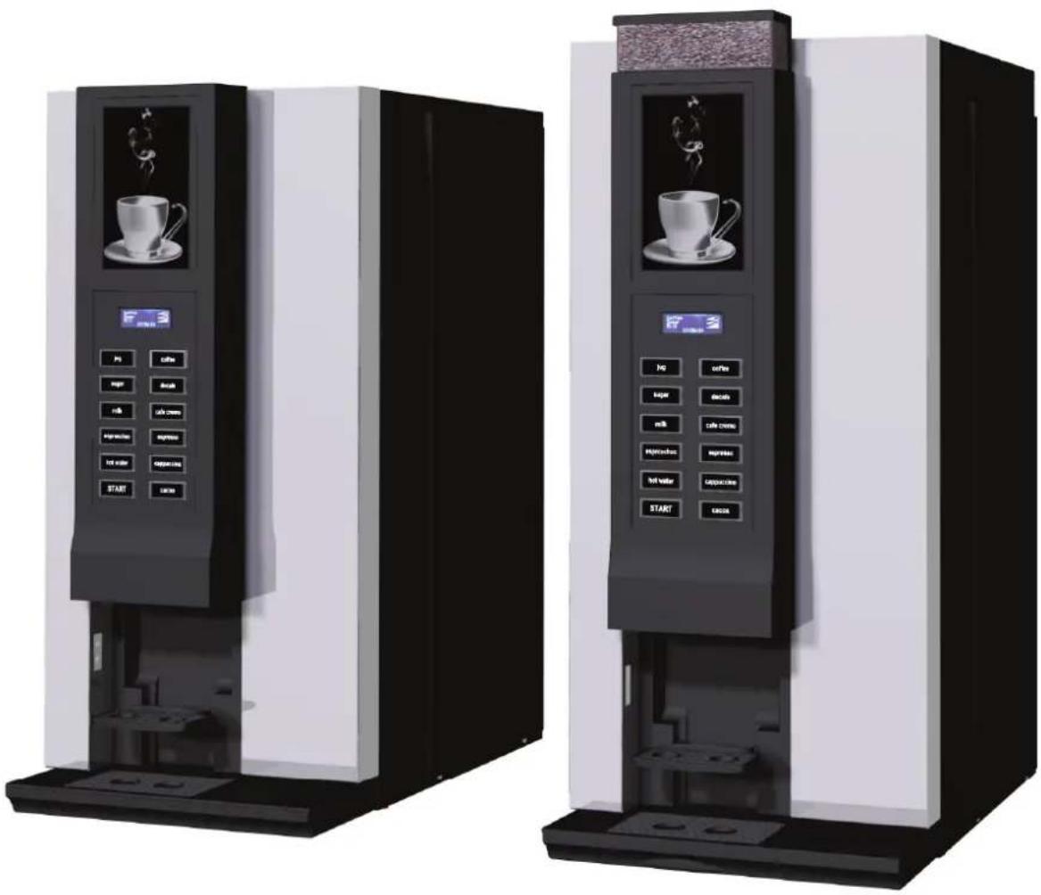
natural_image
Two identical black-and-white industrial coffee vending machines with control buttons and display screens (no visible text or symbols)CE
Instruction for use Nova freshbrew FZ
Manufacturer: ETNA Coffee Technologies b.v.
P.O. Box 146
7000 AC Doetinchem
The Netherlands
Distributor:
© ETNA Coffee Technologies b.v.
Articlecode: 000868640001
Status: Publish
Revision: 2
CONTENTS
1INTRODUCTION....5
1.1Thisusermanual....5
1.2Pictogramsandsafetysymbolsonthemachine....5
1.3Pictogramsandsafetysymbolsinthemanual....5
1.4Conventionsanddefinitions....6
1.5Serviceandtechnicalsupport....6
1.6Machineidentificationonoutsideofthemachine....7
1.7Machineidentificationinsidethemachine....8
1.8Usedmachinesandtheenvironment....8
1.9 Generalsafetyinstructionsandrestrictions....8
1.9.1 Operating and cleaning instructions 9
1.9.2 Icons and instructions 9
1.9.3 Users 9
1.9.4 Technical specifications....9
1.9.5 Modifications 9
1.9.6 Intended use 9
1.10Availabledocumentation....10
2DESCRIPTIONOFTHEMACHINE....11
2.1 Generaldescription.... 1 1
2.2Maincomponents....11
2.2.1 Front view 11
2.2.2 Interior view....12
2.3Containerlay-out....13
2.4Principleofoperation....16
2.5SwitchingONandOFF....16
2.6Servicekey....16
2.7Operatingthemachine....17
2.7.1 Strength selector (if applicable)....17
2.7.2 Selecting jug function 17
2.7.3 Sleep mode....17
3 USE....18
3.1 Safetyinstructions-use....18
3.2Fillingcontainers....19
3.2.1 Filling the container in the machine....19
3.2.2 Filling the ingredient containers outside the machine 19
3.3Digitalphotoframe....20
4MAINTENANCEANDCLEANING. 21
4.1 Safetyinstructions-maintenanceandcleaning....2 1
4.2 Perishable ingredients. 21
4.3Servicepanel....22
4.4 Maintenance....2 2
4.5Dailymaintenance....22
4.5.1 Checking the ingredient containers 23
4.5.2 Empty waste bucket 23
4.5.3 Cleaning drip tray 23
4.5.4 Rinsing mixers 24
4.5.5 Rinse brewer group 24
4.5.6 Cleaning valves 24
4.5.7 Clean the exterior 25
4.6 Weekly maintenance.... 25
4.6.1 Cleaning mixer components....26
4.6.2 Clean the brewer group (weekly) 28
4.6.3 Cleaning the espresso mixer 29
4.7Monthlymaintenance.... 30
4.7.1 Cleaning the brewing group monthly 30
4.8 Maintenance overview.... 31
5RESOLVINGPROBLEMS. 32
5.1LCDdisplayontheselectionpanel.... 3 2
5.1.1 Fault messages 32
5.1.2 Selection panel in programming mode 33
5.1.3 User menu (Operator) 33
5.1.4 Diagram of user menu 34
6TECHNICALSPECIFICATIONS.... 35
6.1 Electricalsystem.... 35
6.2Watersystem.... 35
6.3Soundlevel.... 35
6.4 Ambient conditions.... 3 6
6.5Dimensionsandweight.... 3 6
1INTRODUCTION
1.1 Thisusermanual
Congratulations on the purchase of yourNova freshbrew FZ. This machine has been developed and produced using state-of-the-art technology. This, combined with the ISO 9001 certification that applies to all our products, means you can rest assured that you are the owner of a high quality product.
This manual is intended for authorised and trained users and contains all the information required to operate the machine safely and to carry out regular maintenance and cleaning tasks. Read the relevant user manual carefully before using your machine.

Ensure that the user manual is kept with the machine to ensure that all procedures are carried out correctly.

Figure 1-1
1.2 Pictogramsandsafetysymbolsonthemachine
The following pictograms are used on the Nova freshbrew FZ:
- Electrical hazard
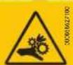
• Risk of fingers being trapped

Figure 1-2
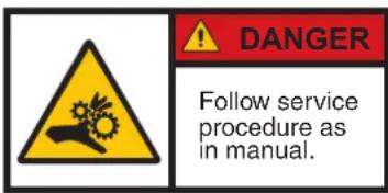
Figure 1-3
1.3 Pictogramsandsafetysymbolsinthemanual
These pictograms are used in the manual:

General warning. Damage to the machine or personal injury can occur.
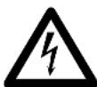
Electrical hazard
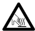
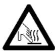
Burning hazard

Remarks, suggestions and advice
1.4 Conventions and definitions
Throughout the document, reference is made to the "left", "right", "front" and "rear" of the machine. Where a component or specific part of the machine is referred to, this is described from the user's viewpoint facing the selection panel.
1.5Serviceandtechnicalsupport
Please contact your dealer for further information on settings, maintenance and/or repair activities that are not dealt with in this manual. Your dealer will be pleased to assist you.
If you contact your dealer, always have the following information at hand:
- model number
- serial number
- software versions
1.6Machineidentificationonoutsideofthemachine
- Model number
- Voltage
- Frequency
- Power rating
- Serial number
- Water pressure
- M.C.C.
The identification plate is on the rear of the machine.
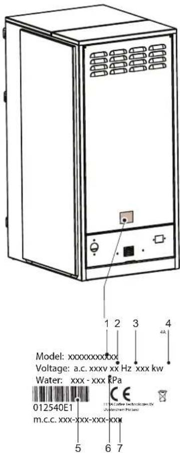
Figure 1-4
1.7 Machineidentificationinsidethemachine
- Model number
- Voltage
- Frequency
- Power rating
- Serial number
- Water pressure
- M.C.C.
The identification plate is on the inside of the left-hand frame plate.
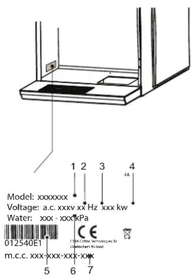
Figure 1-5
1.8 Used machines and the environment

Ask your local authority for information on ways to recycle materials safely and in an environmentally friendly manner.
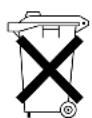
Ask your local authority for information on ways to dispose of materials safely and in an environmentally friendly manner.
1.9 Generalsafetyinstructionsandrestrictions
The manufacturer does not accept liability for any damage caused by any failure to (strictly) observe the safety instructions or by carelessness during use and cleaning of the machine and any associated accessories.
Depending on the specific operating conditions or accessories used, additional safety instructions may apply. Please contact your dealer immediately if you encounter any hazards when using the machine.

The user of the machine is fully responsible at all times for observing locally applicable safety regulations and guidelines.
1.9.1 Operating and cleaning instructions
- All those using and/or cleaning the machine must be familiar with and follow the operating and cleaning instructions closely. The owner must ensure that personnel are informed of the operating and cleaning instructions contained in this manual and that they comply with these regulations and instructions.
- Never change the order in which activities are carried out.
• Always keep these instructions in the vicinity of the machine.
1.9.2Iconsandinstructions
The icons, symbols and instructions attached to the machine form part of the safety instructions. Therefore, they must not be covered or removed. They must be kept within reach and be clearly legible throughout the entire service life of the machine.
- If icons, symbols or instructions are illegible, ring your supplier straightaway to rectify this.
1.9.3Users
The daily, weekly and monthly maintenance and cleaning activities may only be carried out by users who have received training from the installer or owner of the machine. These individuals will be familiar with the potential risks of opening the machine.
1.9.4 Technical specifications
- The technical specifications may not be modified.
1.9.5 Modifications
- Modifications may not be made to the machine (or parts of the machine).
1.9.6 Intendeduse
The intended use ^1 of the machine is designed exclusively for dispensing beverages as indicated on the selection panel. Use of the machine for any other purpose falls outside the terms of conditions of use. The manufacturer does not accept responsibility for any damage or injury that may result from improper use.
The machine meets current standards and directives.
- The machine may only be used in perfect technical condition for the purposes indicated above.
1.10 Available documentation
The following documentation is available for this machine:
- User manual
- Technical manual
- Parts book
2DESCRIPTIONOFTHEMACHINE
2.1 Generaldescription
This machine prepares and dispenses various hot drinks.
The drinks are dispensed in the cups intended for this purpose and that are placed on the machine cup stand. The cups must be placed on the cup stand manually.
The display on the machine indicates that:
- a drink can be selected
• a drink is being prepared - a fault has occurred.
• the machine is performing a function.
2.2 Maincomponents
2.2.1 Frontview
- Window (optional: photo frame)
- Display
- Selection panel
- Cup sensor
- Cup stand (two-sided)
- Drip tray
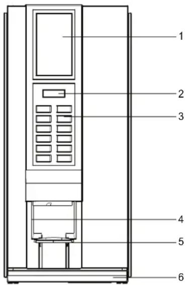
Figure 2-1
- Bean container
- Light panel (optional: photo frame)
- Display
- Selection panel
- Cup sensor
- Cup stand (dual)
- Drip tray
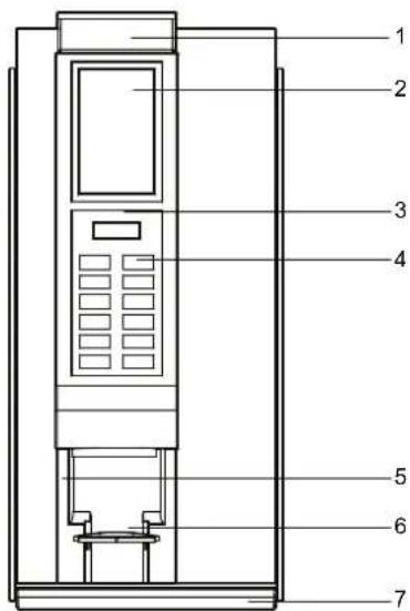
Figure 2-2
2.2.2 Interiorview
- Ingredient containers
- Dispensing spout
- Mixer parts
- Dispenser holder
- Waste container
- Espresso mixer (optional)
- Zuma brewer (brewer group)
- Service switch
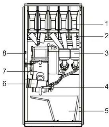
Figure 2-3
- Ingredient containers
- Dispensing spout
- Mixer parts
- Dispenser holder
- Waste container
- Espresso mixer (optional)
- Zuma brewer (brewer group)
- Service switch
- Bean grinder
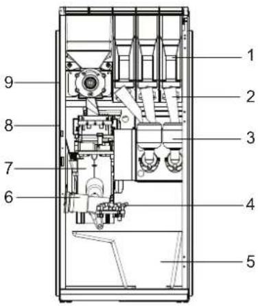
Figure 2-4
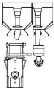
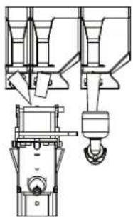
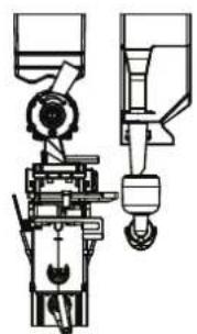
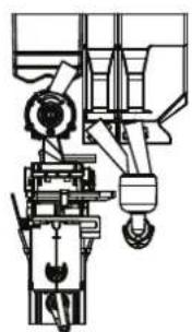
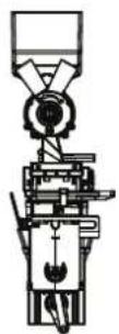
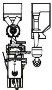
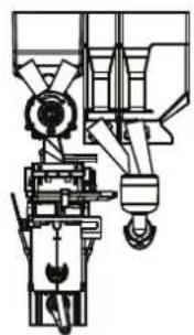
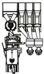
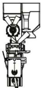
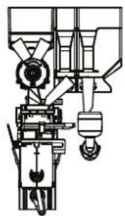
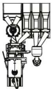
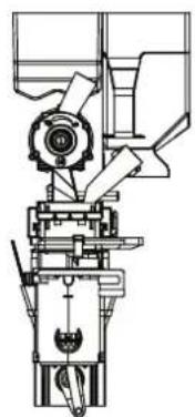
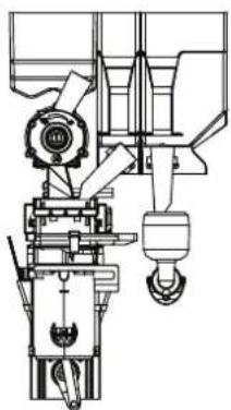
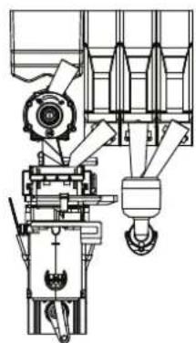
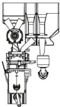
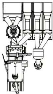
2.3Containerlay-out
The various types are fitted with the following containers.
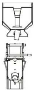
FZ100 FZ111 FZ121 FZ132
natural_image
Technical line drawing of a mechanical device with no visible text or symbols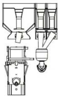
natural_image
Technical line drawing of a mechanical device with no visible text or symbols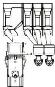
natural_image
Technical line drawing of a mechanical assembly with multiple components and mounting holes (no text or labels)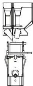
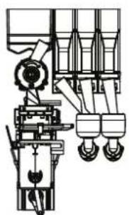
FZ200 FZ211 FZ221 FZ232
natural_image
Technical line drawing of a mechanical device with no visible text or symbols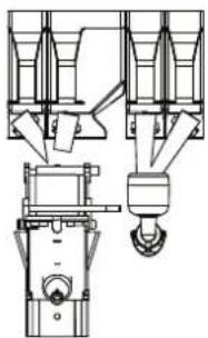
natural_image
Technical line drawing of a mechanical assembly with no visible text or symbols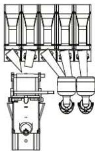
natural_image
Technical line drawing of a mechanical assembly with three vertical supports and two hanging weights (no text or symbols)Figure 2-5
| MachineFreshbrewcontainer | Instantcontainer |
| Nova FZ100 1x 6 L | |
| Nova FZ200 1x 1.8 l | |
| 1x 3.9 l |
| MachineFreshbrewcontainer | Instantcontainer | |
| Nova FZ111 | 1x 6 L | 1x 3.9 l |
| Nova FZ211 1x 1.8 l | 1x 3.9 l | 1x 3.9 l |
| Nova FZ121 | 1x 6 L | 2x 1.8 l |
| Nova FZ221 1x 1.8 l | 1x 3.9 l | 2x 1.8 l |
| Nova FZ132 | 1x 3.9 l | 3x 1.8 l |
| Nova FZ232 | 2x 1.8 l | 3x 1.8 l |
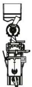
BZ 100
natural_image
Technical line drawing of a mechanical assembly with no visible text or symbolsBZ 111
natural_image
Technical line drawing of a mechanical assembly with no visible text or symbolsBZ 121
natural_image
Technical line drawing of a mechanical lifting device with no visible text or symbolsBZ 132
BZ 200
natural_image
Technical line drawing of a mechanical device with no visible text or symbolsBZ 211
natural_image
Technical line drawing of a mechanical assembly with no visible text or symbolsBZ 221
natural_image
Technical line drawing of a mechanical lifting device with no visible text or symbolsBZ 232
natural_image
Technical line drawing of a mechanical assembly (no text or symbols visible)BZ 300 BZ 311
natural_image
Technical line drawing of a mechanical assembly with no visible text or symbolsFigure 2-6
natural_image
Technical line drawing of a mechanical assembly with no visible text or symbolsBZ 321
| MachineFreshbrew Container | wcon- | |
| Nova BZ100 1x 2.9 l | ||
| Nova BZ111 | 1x 2.9 l | 1x 4.8 l |
| Nova BZ121 | 1x 2.9 l | 1x 2.3 l 1x 4.8 l |
| Nova BZ132 | 1x 2.9 l | 3x 2.3 l |
| Nova BZ200 2x 1.4 l | ||
| Nova BZ221 | 2x 1.4 l | 1x 2.3 l 1x 4.8 l |
| Nova BZ232 | 2x 1.4 l | 3x 2.3 l |
| Nova BZ300 | 2x 1.4 l | 1x 4.8 l |
| Nova BZ311 | 2x 1.4 l | 1x 2.3 l 1x 4.8 l |
| Nova BZ321 | 2x 1.4 l | 3x 2.3 l |
natural_image
Technical line drawing of a mechanical assembly (no text or symbols visible)BT 200
natural_image
Technical line drawing of a mechanical assembly with gears and levers (no text or symbols)BT 211 BT 221
natural_image
Technical line drawing of a mechanical assembly with no visible text or symbols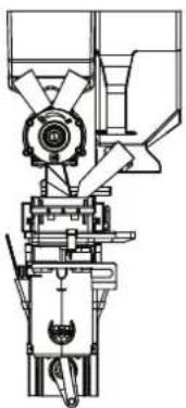
natural_image
Technical line drawing of a mechanical device with no visible text or symbolsBT 300
natural_image
Technical line drawing of a mechanical device with gears and pump (no text or symbols)BT 311
natural_image
Technical line drawing of a mechanical device with no visible text or symbolsBT 321
Figure 2-7
| MachineBeancontainer | Teacontainer | Instantcoffee | container |
| Nova BT200 | 1x 2.9 l | 1x 4.8 l | |
| Nova BT211 | 1x 2.9 l | 1x 2.3 l | 1x 4.8 l |
| Nova BT221 | 1x 2.9 l | 1x 2.3 l | 2x 2.3 l |
| Nova BT300 | 2x 1.4 l | 1x 4.8 l | |
| Nova BT311 | 2x 1.4 l | 1x 2.3 l | 1x 4.8 l |
| Nova BT321 | 2x 1.4 l | 1x 2.3 l | 2x 2.3 l |
2.4Principleofoperation
After a selection is made, the drink is prepared and dispensed.
• The water is supplied via the boiler (heated).
- Instant products are dosed from the containers into the mixer and/or the ground coffee is dosed into the brewing group.
- The water and the ingredients are mixed in the mixer or compressed by the brewing group.
- The drink is dispensed through the dispensing pipe into the cup placed on the cup stand.
- The cup stand has two sides; hot water on the left, drinks on the right.
- The start button can be used when a drink has been selected and a cup has been placed.
2.5SwitchingONandOFF
The machine is not fitted with a manually operated on/off switch. The key-operated switch with which the door is opened contains the on/off switch.
- When the door is opened, the machine switches itself off.
- When the door is closed, the machine switches itself back on.
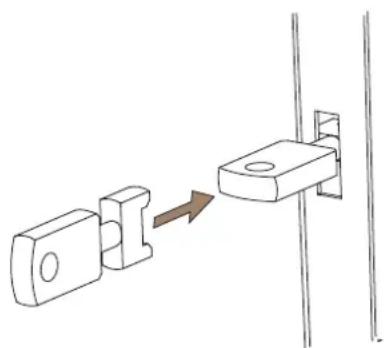
2.6Servicekey
Once the service key has been inserted and turned a quarter turn, the machine is operational for repair and test purposes.

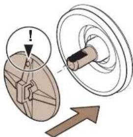
The machine contains rotating and moving parts. Ensure that your fingers do not become trapped when work is carried out.
natural_image
Diagram showing a mechanical component being inserted into a bracket, with an arrow indicating the process (no text or symbols present)Figure 2-8
2.7 Operatingthemachine
The standard version of the machine has no payment mechanism. The machine can also be optionally fitted with a payment mechanism (for installation instructions, see the instructions for use supplied with the payment mechanism).
2.7.1 Strengthselector(ifapplicable)
Select the drink by pressing the button.
The strength can be changed by pressing the selected drink again.
This is also an option when adding items such as sugar and milk, if the machine allows for this.
2.7.2 Selectingjugfunction

If the jug function is switched on the cup sensor is switched off.
The jug function allows you to select more than one cup at once. This button operates with all available drinks. The procedure for selecting more than one cup is described below.
- Push the cup stand up and put a jug under the dispensing nozzle.
- Use the jug function button and press the desired selection button several times.
- Now operate the MILK and/or SUGAR buttons to obtain the required combination.
- Press the START selection button for the required drink. The jug is filled. Ensure that the jug is large enough for the number of cups selected.
If you want to reduce the number of cups while the machine is dispensing, press the Jug function button several times until the required number is displayed. The machine will then stop after the cup that is currently being dispensed.
If the machine is equipped with a coin mechanism and a key switch for the jug function, you can activate the free drink dispensing mode by placing the key in the slot (the switch) and turning it to the right.
2.7.3 Sleepmode
The characteristics of sleep mode are:
- Buttons are not illuminated.
- Display is not illuminated.
• Light panel or photo frame (optional) are on. - Start button lights up red.
Press a button to bring the machine out of sleep mode.
3USE
3.1 Safetyinstructions-use
- Inspect the machine before use and check for any damage and defects.
Please contact your supplier if there is any damage to the machine. - Please keep all packaging out of reach of children.
- Put the machine in a horizontal position.
- Put the machine in a location where it can be supervised by trained staff.
- The machine may not be used by persons (including children) with limited physical, mental or emotional capacity, or with insufficient knowledge and experience to operate the machine without supervision or instructions until they have been approved by somebody, who is responsible for their safety.
- Children must be supervised to ensure they do not play with the machine.
- Protect the machine from water and/or moisture.
- Do not clean the machine using a high pressure water jet.
- Keep the buttons free from dirt and grease, clean them regularly.
- Only use the machine when the top valves are closed and all plates have been fitted.
- Never use sharp objects to operate the buttons.
- Only use the cups and jugs that are available at the counter.
- Ensure that the wall socket (with earth connection) and the water connection point remain accessible during use. In case of emergency, the mains plug can then be removed quickly and the water supply can be shut off immediately.
- If the machine is not being used for extended periods of time: remove the holders, disinfect the pipes, clean the machine by hand, clean and disinfect the mixing components thoroughly, empty the boiler, disconnect the water supply and mains electricity supply. No water should be left standing in the machine or any of its parts.
- If you wish to subsequently use the machine following a lengthy period of disuse, you need to thoroughly clean the mixing components and the preparation group (if present). Replace the mixing components, complete the cleaning program at least three times and fill all the holders before you start to use the machine.
The drinks that are supplied by this machine are very hot and can cause injuries.
Remove the plug from the wall socket in the event of any danger. Do not pull the plug from the wall socket using the cable.

Disregarding the above instructions can jeopardise the safe use of the machine.
3.2 Fillingcontainers
The containers contain the ingredients for preparing the drinks. There are 2 ways of filling these containers:
- by opening the top lid and filling the container in the machine;
• by filling the container outside of the machine.
3.2.1 Fillingthecontainerinthemachine
- Open the door of the machine.
- Open the lid on the container that needs refilling. Refill the container with the correct ingredients.
- Close the upper lid.
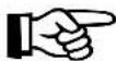
- If the container was completely empty, the supply will need refilling.
- Hold the container above the waste bucket. Turn the spindle of the container until the ingredient runs out of it.
3.2.2 Filling the ingredient containers outside the machine
The containers hold the ingredients required to prepare drinks.

Ensure that no fingers are trapped when filling the containers.
Make sure that the right ingredient is put in the correct container.

See the label on the inside of the door for an overview of the maintenance functions.
- Open the door of the machine.
- Open the upper lid.
- If necessary, remove the filling plate.
- Lift the containers being filled out of the holder and pull them towards you.
- Fill the container with the required ingredient.
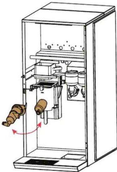
- Replace the container in the machine in its original position. Ensure that the coupling of the container latches onto the gear.
- Repeat this procedure for the other ingredients containers.
- If present, fit the filling plate.
- Close the cover.
- Place a 1.5 l cup under the dispensing spout.
- Insert the service key and turn it a quarter turn (if applicable).
- Press button 0 on the service panel; clean valves. The valves will be rinsed with water. Repeat if necessary (if applicable).
- Turn the service key a quarter turn and remove (if applicable).
- Close the door of the machine.
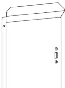
3.3Digitalphotoframe

See the supplied manuals for correct use of the remote control and Digital Photo Frame.
When the door is opened, the USB connection is displayed on the door plate on the inside of the door.
Operating the photoframe

The photo display is operated with the remote control.
The photos can be stored on a memory card (SD, MS, MMC, XD). The photos must be RGB JPG files.
1 Select Photo from the main menu and press Enter or OK.
The photo browser is displayed.
2 Select the directory containing the photos that are to be displayed.
3 Press ENTER or OK.
4 The photos are displayed automatically.
Changingphotos
1 Select Edit from the main menu and press Enter or OK.
2 The Edit menu is displayed.
Select from: Copy, Delete or Edit
3 You can navigate through the menu using the arrow keys.
The selection is confirmed by pressing Enter or OK.
natural_image
Line drawing of an open electrical cabinet with a door and two terminals (no text or symbols)Figure 3-1
4MAINTENANCEANDCLEANING
Accurate maintenance and in particular careful cleaning are basic conditions for good product quality and smooth operation.
This device is designed so that the owner or license holder is able to clean and maintain it thoroughly in a relatively short time.
First read paragraph 4.1 before performing any maintenance work on the device. The maintenance work described may only be carried out by trained and authorised users.
4.1 Safety instructions-maintenance and cleaning
• See also par. 3.1.
- Carry out the procedures taking into account the hygiene regulations.
- Repairs may only be carried out on the machine by trained service engineers.
- Maintenance work on the electrical system may only be carried out by trained service engineers with a background in electrical engineering.
Warning with respect to burns: parts within the machine can be very hot.
- After cleaning or maintenance activities, the machine must not be used until all the removed parts have been correctly reinstalled.
Then inspect and check the inside of the machine:
- The dispenser holder must be aimed at the middle of the cup.
• The ingredient containers must be correctly placed. - The mixer components must be in the correct position.
- The waste container must be in the correct position. (if applicable)
- The brewer group must be in the correct position. (if applicable)
4.2 Perishable ingredients

The ingredients have been supplied with a use by date. The following therefore needs to be taken into account:
- Comply with the use by date printed on the product packaging.
- Do not use ingredients, which are approaching the use by date.
- Replace any ingredients whose use by date has passed.
- Do not use opened ingredients for longer than the use by date indicated.
- Replace any opened ingredients whose use by date has passed.
- Only use the cleaning agents referred to in the cleaning schedule and follow the instructions on the packaging.
4.3Servicepanel
The service panel will become visible when the door is opened. The following maintenance activities can be carried out via the service panel (if present):
| ButtonFunction | |
| 1 Cleaning the Brewer daily/monthly | |
| 2 Rinse mixer 1 | |
| 3 Rinse mixer 2 | |
| 4 | |
| 5 Open / close brewer group | |
| 6 | Free / paid for dispensing on or off |
| 7 | |
| 8 Drink counters | |
| 9 | |
| 0 | Clean valves + rinse brewer group |
| # | Enter programme or cancel the active rinsing |
Figure 4-1
4.4 Maintenance
The quality of the drinks is only guaranteed if the machine is properly maintained on a regular basis. A number of essential components in the machine are highly sensitive to dirt. Use of this machine requires both daily and weekly maintenance.
4.5Dailymaintenance
Carry out the following operations on a daily basis:
- Check the contents of the ingredient containers and refill them if necessary.
- Clean and empty the waste bucket underneath the brewing group.
• Clean and empty the drip tray. - Rinse the mixers and valves (at least 2x a day).
- Clean the outside of the machine, including the selection panel.
- Rinse the brewer group.
When cleaning the machine, pay attention to the following:
- Clean the machine and its parts with a damp, clean cloth or paper towel.
• Always put the cleaned parts back into the machine without delay. - If necessary, clean the machine more often than indicated. If it is used frequently, this will certainly be required.
4.5.1 Checkingtheingredientcontainers
- Open the door.
- Check whether the ingredient containers still contain sufficient ingredients.
- If necessary, prime the containers as described in (see chapter 3.2).
- Close the door.
4.5.2 Emptywastebucket
- Open the door.
- Remove the waste container from the machine and empty it.
- Clean the waste bucket with water.
- Put the waste bucket back again.
- Insert the service key and turn it a quarter turn.
- Press button 9 on the service panel to reset the waste counter to 0.
- Turn the service key a quarter turn and remove it.
- Close the door of the machine.

Use plastic bags in the waste bucket for hygiene reasons.
4.5.3 Cleaningdriptray

The drip tray must not be washed in a dishwasher.
- Take the drip tray out of the machine carefully.
- Empty the drip tray and clean it using water.
- Put the drip tray back in the machine.
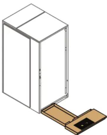
natural_image
Isometric line drawing of a cabinet with an open door and wooden base (no text or symbols)Figure 4-2
4.5.4 Rinsingmixers
Drinks dispensed by this machine are very hot and may cause burns.
- Open the door and insert the service key.
- Place a cup or jug (min. 0.5 l) under the dispensing spout.
- To rinse only the mixers, press button 2, 3 or 4.
-
To rinse the brewer group and/or mixer(s) several times in succession:
-
Press the jug button (selection panel) to set the number of rinses;
- Press buttons 2, 3, or 4 to rinse the relevant mixer(s);
-
the mixer(s) is/are now rinsed the set number of times.
-
Remove the cup or jug.
-
Turn the service key a quarter turn and remove it.
- Close the door of the machine.

N.B.: Ensure that the jug or cup is big enough to collect the rinsing water.
4.5.5 Rinsebrewergroup
Drinks dispensed by this machine are very hot and may cause burns.
- Open the door and insert the service key.
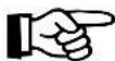
- Place a cup or jug measuring a min. 1.5 l under the dispenser holder.
- Press button 1 on the service panel; rinse brewer group.
- Select "Daily", press Start.
- The brewer group is now cleaned.
- Remove the cup or jug.
- Turn the service key a quarter turn and remove it.
- Close the door of the machine.
4.5.6 Cleaning valves
Drinks dispensed by this machine are very hot and may cause burns.
- Open the door and insert the service key.
- Place a cup of at least 1.5 L under the dispensing holder.
- Press button 0 on the service panel; clean valves.
- All valves are cleaned.
- Remove the cup.
- Turn the service key a quarter turn and remove it.
- Close the door of the machine.
- Empty the cup.
4.5.7 Cleanthe exterior
Clean the outside of the machine with a damp, clean cloth or paper towel. Pay special attention to:
- The selection panel
• The area around the drink dispenser unit.
• The bottom of the door.
4.6 Weekly maintenance
Carry out the following operations on a weekly basis:
• Clean the mixer components (take apart)
- Clean the brewer group, using the stipulated cleaning agent
- Clean the espresso mixer (take apart), if available.
4.6.1 Cleaningmixercomponents
Clean the following components during weekly maintenance:
- Extractors
- Mixing bowls
- Hoses
- Extraction lid

Wash your hands before continuing with this procedure.
- Open the door.
- Remove the closed ingredient containers from the machine. Store in a dry, clean place.
- Detach the hoses from the mixing chambers.
- Detach the hoses from the dispensing pipes.
- Remove the dispensing pipes from the dispensing holder.
- Release the mixing chamber by pulling the green catch below it forwards.
- Take the mixing compartment out of the machine by carefully pulling the bottom of the compartment towards you.
- Take the suction filter cover out of the machine.
- Use the tool to remove the mixer blade from the shaft of the motor. Move the tool forwards carefully until it clicks. Then remove the mixer blade manually.
- Clean all parts in hot water and dry them carefully.
- Clean the area directly surrounding the mixer in the machine with a damp, clean cloth.
flowchart
graph TD
    A["Water Pump"] --> B["Reinjection"]
    B --> C["Reinjection of funnel"]
    C --> D["Reinjection of toilet"]
    D --> E["Reinjection of outlet"]
    E --> F["Reinjection of toilet"]
    F --> G["Reinjection of outlet"]
    G --> H["Reinjection of inlet"]
    H --> I["Reinjection of outlet"]
Figure 4-3
- Put the mixer blade back in place. Ensure that the marker on the mixer blade is aligned with the flat part on the motor shaft.
- Put the other cleaned parts back into the machine and connect the hoses.
The mixing compartment must latch securely in place to prevent leaks. Ensure that the green catch snaps back into place.
- Insert the service key and turn it a quarter turn.
- Place a 1.5 l cup under the dispenser holder.
- Press button 0 on the service panel; clean valves.
- Check that nothing leaks.
18.Remove the cup or jug. - Turn the service key a quarter turn and remove it.
- Close the door of the machine.

natural_image
Diagram showing a mechanical component with an arrow indicating direction, no text or symbols presentFigure 4-4
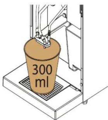
Figure 4-5
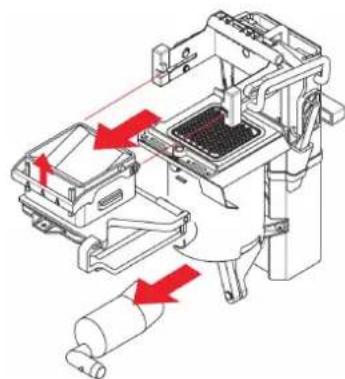
4.6.2 Cleanthebrewergroup(weekly)
- Open the door.
- Insert the service key.
- Place a cup or jug (min. 0.5 l) under the dispensing spout.
- Press button 1 on the service panel on the inside of the machine.
- Add the cleaning agent into the brewer compartment.
- The display now indicates daily cleaning/monthly cleaning, select daily cleaning and press the START button on the front of the machine.
- Daily cleaning is now activated. Cleaning takes approximately 4 minutes.
- Press button 5 on the service panel on the inside of the machine to open the brewer.
- Remove the brewer compartment and the outlet.

The brewer group must not be washed in a dishwasher.
-
Clean the brewer compartment and the outlet with hot water. Align the arrows on the brewer compartment before re-fitting it.
-
Fit the brewer compartment and the outlet.
- Press button 5 on the service panel on the inside of the machine to close the brewer.
- Remove the cup or jug.
- Turn the service key a quarter turn and remove it.
- Close the door of the machine.
natural_image
Technical diagram of a mechanical device with red arrows indicating motion or force directions (no text or symbols present)Figure 4-6
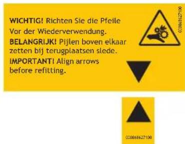
Figure 4-7
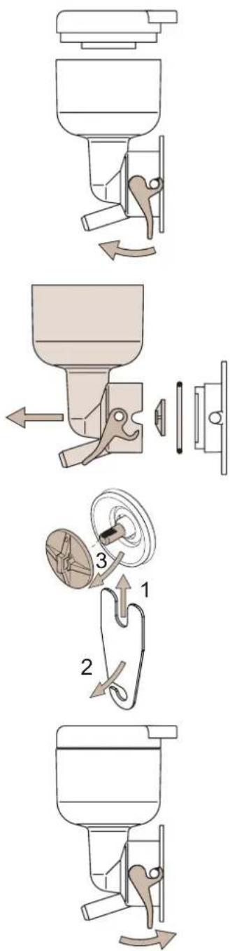
4.6.3Cleaningtheespressomixer
- Open the door.
- Remove the dispensing holder from the espresso mixer.
- Disconnect the espresso mixer from the brewing group outlet.
- Detach the mixer chamber from the holder by rotating it towards you.
- Clean the parts in hot water and dry them carefully.
- Fit the cleaned parts and connect the hose.
- Take the mixing compartment out of the machine by carefully pulling the bottom of the compartment towards you.
- Take the suction filter cover out of the machine.
- Use the tool to remove the mixer blade from the shaft of the motor. Move the tool forwards carefully until it clicks. Then remove the mixer blade manually.
- Clean all parts in hot water and dry them carefully.
-
Clean the area directly surrounding the mixer in the machine with a damp, clean cloth.
-
Put the mixer blade back in place. Ensure that the marker on the mixer blade is aligned with the flat part on the motor shaft.
- Put the other cleaned parts back into the machine and connect the hoses.
The mixing compartment must latch securely in place to prevent leaks. Ensure that the green catch snaps back into place.
- Insert the service key and turn it a quarter turn.
- Place a 1.5 l cup under the dispenser holder.
- Press button 0 on the service panel; clean valves.
- Check that nothing leaks.
- Remove the cup or jug.
- Turn the service key a quarter turn and remove it.
- Close the door of the machine.
natural_image
Technical line drawing of a mechanical device with internal components and directional arrows (no text or symbols)Figure 4-8 Removing the espresso mixer
natural_image
Diagram showing a mechanical component with an arrow indicating direction, no text or symbols presentFigure 4-9
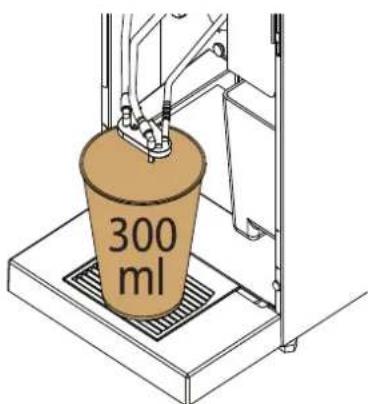
Figure 4-10
4.7Monthlymaintenance
The following activities should be carried out monthly:
• Clean the mixer parts, (see paragraph 4.6.1)
• Clean the brewer group manually
- Clean the brewer group, using the stipulated cleaning agent
• Clean the espresso mixer, (see paragraph 4.6.2)
4.7.1 Cleaningthebrewinggroupmonthly

Only use the cleaning agent recommended by the ETNA (see appendix). Other cleaning agents may affect the construction of the brewer group.
- Open the door and insert the service key.
- Insert a cup or 1.5 l jug under the machine outlet.
- Press button 1 on the service panel on the inside of the machine.
- Add the cleaning agent into the brewer compartment.
- The display now indicates daily cleaning/monthly cleaning, select monthly cleaning and press the START button on the front of the machine.
- Monthly cleaning is started and will take about 7 minutes.
- Press button 5 on the service panel on the inside of the machine to open the brewer.
- Disconnect the water supply to the brewer, remove the brewer compartment.
- Remove the brewer from the machine.
- Put the complete brewer back into the machine and re-fit the brewer compartment.
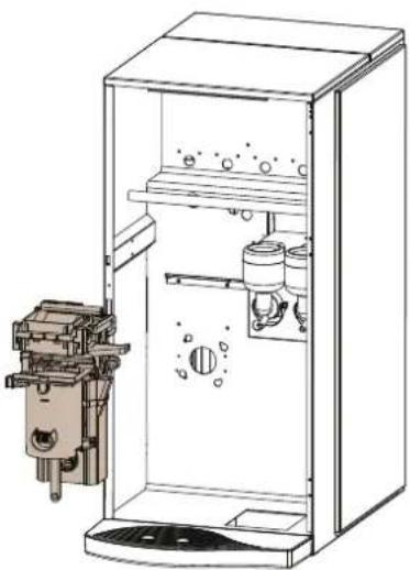
natural_image
Technical line drawing of a mechanical device inside a transparent enclosure, showing internal components and mounting base (no text or symbols)
Align the arrows on the brewer compartment before refitting it.
- Press button 5 on the service panel on the inside of the machine to close the brewer.
- Remove the cup or jug.
- Turn the service key a quarter turn and remove it.
- Close the door of the machine.
IMPORTANT! Align arrows before refitting.

4.8 Maintenance overview
The labels with an overview of the maintenance to be carried out have been stuck to the inside of the door.
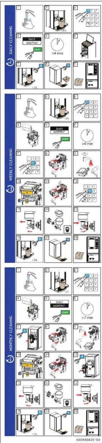
Figure 4-11
5RESOLVINGPROBLEMS
5.1LCDdisplayontheselectionpanel
If faults occur in the machine, the LCD display on the selection panel will display a fault message.
5.1.1 Faultmessages
Despite taking all precautionary measures, faults may occur in the machine. In this case, a fault message is displayed. The table below (if applicable) shows a number of faults that could occur, their cause and their remedy.
| FaultmessageCauseRemedy | ||
| Fill container x | Container x is empty | Fill the container and reset the fault message, see Filling containers |
| Empty waste bucket | The waste bucket is full | Empty waste bucket and clean it, see Emptying waste bucket |
| Rinse brewing group | Rinse the brewing group, see Cleaning the brewing group automatically | |
| Cleaning the brewing group | Cleaning the brewing group manually, see Cleaning the brewing group | |
| Empty drip tray | The drip tray is full | Empty drip tray, see Cleaning drip tray |
| Exact change | Not enough change in money changer | Pay with exact change |
| Drink switched off | Selected drink not available | Contact your supplier |
| Replace lime scale filter | Filter has exceeded its service life | Replace the filter |
| Boiler is heating up | Boiler temperature is too low | Wait until the boiler has heated up |
| No water | Water level too low | Check the machine's water supply |
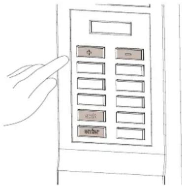
5.1.2 Selectionpanelinprogrammingmode
When the programming mode is used, the selection panel has the following functions:
-
- or -, these keys are used to navigate the menu, or to increase or decrease values.
- START, this key confirms the value that is set.
-
(on the service panel), this key is used to navigate back through the menu.
5.1.3Usermenu(Operator)
Press # on the service panel and enter the PIN code.
The standard PIN code for the user menu is 4321.
| MenusubjectDescription | |
| Beverage counters | - reading the counter settings per drink- resetting the counter settings |
| Time & date | - changing time- changing date- changing day- switching on/off on display- setting time adjustment |
| Temperature | - change the temperature (set water by default 95°C,) - setting the sensor |
| Payment system | -read in user menu |
| Pin code | - read in user menu |
| Machine info. | - read out the machine type, display, time, date, language, water filter, etc. |
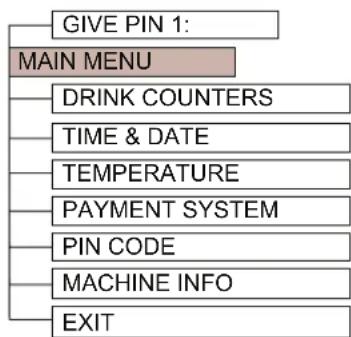
flowchart
graph TD
    A["GIVE PIN 1:"] --> B["MAIN MENU"]
    B --> C["DRINK COUNTERS"]
    C --> D["TIME & DATE"]
    D --> E["TEMPERATURE"]
    E --> F["PAYMENT SYSTEM"]
    F --> G["PIN CODE"]
    G --> H["MACHINE INFO"]
    H --> I["EXIT"]
Figure 5-1
5.1.4 Diagramofusermenu
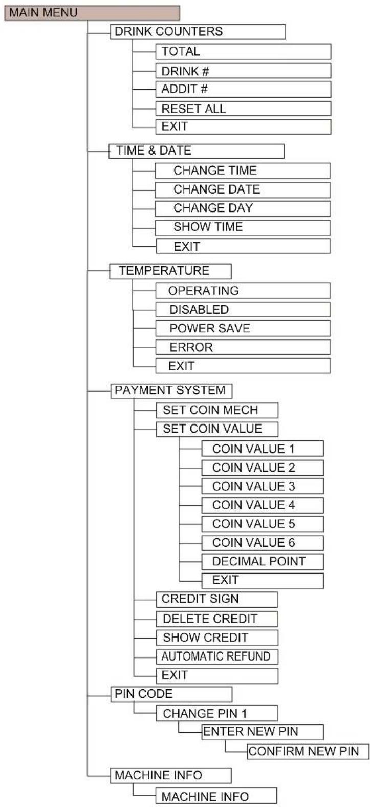
flowchart
graph TD
    A["MAIN MENU"] --> B["DRINK COUNTERS"]
    B --> B1["TOTAL"]
    B --> B2["DRINK #"]
    B --> B3["ADDIT #"]
    B --> B4["RESET ALL"]
    B --> B5["EXIT"]
    A --> C["TIME & DATE"]
    C --> C1["CHANGE TIME"]
    C --> C2["CHANGE DATE"]
    C --> C3["CHANGE DAY"]
    C --> C4["SHOW TIME"]
    C --> C5["EXIT"]
    A --> D["TEMPERATURE"]
    D --> D1["OPERATING"]
    D --> D2["DISABLED"]
    D --> D3["POWER SAVE"]
    D --> D4["ERROR"]
    D --> D5["EXIT"]
    A --> E["PAYMENT SYSTEM"]
    E --> E1["SET COIN MECH"]
    E --> E2["SET COIN VALUE"]
    E2 --> E2a["COIN VALUE 1"]
    E2 --> E2b["COIN VALUE 2"]
    E2 --> E2c["COIN VALUE 3"]
    E2 --> E2d["COIN VALUE 4"]
    E2 --> E2e["COIN VALUE 5"]
    E2 --> E2f["COIN VALUE 6"]
    E2 --> E2g["DECIMAL POINT"]
    E2 --> E2h["EXIT"]
    E --> F["CREDIT SIGN"]
    F --> F1["DELETE CREDIT"]
    F --> F2["SHOW CREDIT"]
    F --> F3["AUTOMATIC REFUND"]
    F --> F4["EXIT"]
    A --> G["PIN CODE"]
    G --> G1["CHANGE PIN 1"]
    G1 --> G1a["ENTER NEW PIN"]
    G1 --> G1b["CONFIRM NEW PIN"]
    A --> H["MACHINE INFO"]
    H --> H1["MACHINE INFO"]
Figure 5-2
6TECHNICALSPECIFICATIONS
6.1 Electricalsystem

Refer to the machine type plate for the correct configuration of your machine, see Chapter 1: Machine identification.
| DescriptionValue | |
| Main voltage 230 V | |
| Frequency 50 Hz | |
| Capacity 2.31 kW | |
| Fuse 13 A |
6.2 Watersystem
| DescriptionValue | |
| Water connection | G 3/4" - outer ring |
| Minimum water pressure | 1.5 bar (150 kPa) |
| Maximum permitted water pressure | 8 bar (800 kPa) ^1 |
- It the pressure is higher, a pressure reducer must be installed.
6.3 Soundlevel
| DescriptionValue | |
| In operation max. 70 dB(A) |
Measurements according to DIN 45635, with normal use.
6.4 Ambient conditions
| DescriptionValue | |
| Ambient temperature | 5 - 40 °C |

Never place the machine in a room in which the temperature may drop below 0^ C. This is to keep the water in the machine from freezing.
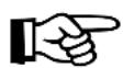
6.5Dimensionsandweight
Nova:
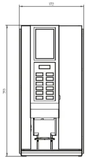
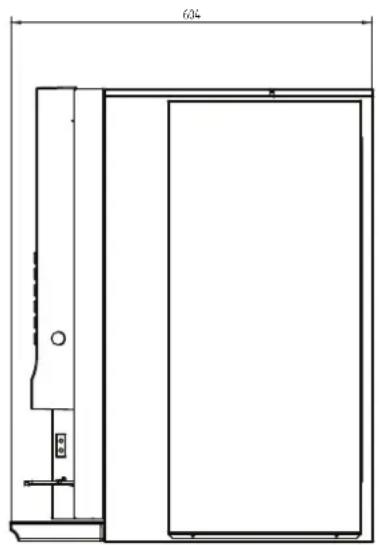
natural_image
Technical line drawing of a door frame with height dimension labeled 604 (no text or symbols beyond measurement)
Figure 6-1
| DescriptionValue | |
| Height 759 mm | |
| Width 372 mm | |
| Depth 604 mm | |
| Weight when empty 38 kg | |
| Weight when full 42.5 kg |