
VWP-2110 - Video Conferencing System Black Box - Free user manual and instructions
Find the device manual for free VWP-2110 Black Box in PDF.


| Product Type | Radian Video Wall Processor |
| Model Number | VWP-2110 |
| Processor | Intel Core i7 4770S, 3.1 GHz |
| Memory | 16 GB DDR3 RAM |
| Storage | 2 x Western Digital RED 750 GB HDD (RAID 1) |
| Optical Drive | DVD/RW Combo Drive |
| Network | Dual 10/100/1000BASE-T Ethernet |
| Expansion Slots | 11 x PCIe x8 slots (switched fabric backplane) |
| Maximum Video Outputs | Up to 64 (with up to 16 Video Graphics Cards) |
| Power Supply | 800 W |
| Dimensions (H x W x D) | 6.8 x 19 x 19.7 in (17.5 x 48.2 x 50 cm) |
| Weight | 41.8–55 lb (19–25 kg) |
| Operating Temperature | 32 to 95°F (0 to 35°C) |
| Compliance | FCC, CE, RoHS, UL, CCC |
| Control Software | VWS-2001 Video Wall Control Software (pre-installed) |
| Included Accessories | USB keyboard, USB mouse, 2 power cables, Windows OS CD, DVI-VGA adapter, ribbon cables |
| Filter Maintenance | Clean every 3 months (vacuum or shake); screw removal required |
Frequently Asked Questions - VWP-2110 Black Box
User questions about VWP-2110 Black Box
0 question about this device. Answer the ones you know or ask your own.
Ask a new question about this device
Download the instructions for your Video Conferencing System in PDF format for free! Find your manual VWP-2110 - Black Box and take your electronic device back in hand. On this page are published all the documents necessary for the use of your device. VWP-2110 by Black Box.
USER MANUAL VWP-2110 Black Box
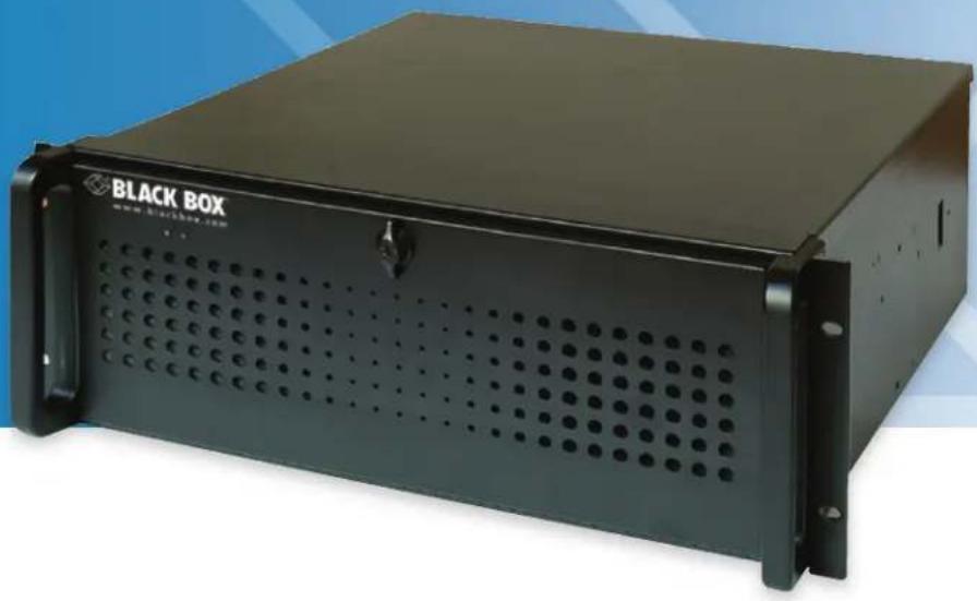
Radian Video Wall Processor
User Manual
natural_image
Black Box server unit with perforated ventilation slots and mounting bracket (no visible text or symbols on body)Trademarks Used in this Manual
Black Box and the Double Diamond logo are registered trademarks of BB Technologies, Inc.
ASUS is a registered trademark of Asustek Computer Inc.
Intel is a trademark of Intel Corporation or its subsidiaries in the U.S. and/or other countries.
Microsoft and Windows are either registered trademarks or trademarks of Microsoft Corporation in the United States and/or other countries.
PCI Express is a US registered trademark and/or service mark of PCI-SIG.
StreamPix is a registered trademark of Comcast Corporation.
Any other trademarks mentioned in this manual are acknowledged to be the property of the trademark owners.
We're here to help! If you have any questions about your application or our products, contact Black Box Tech Support at 877-877-2269 or go to blackbox.com and click on "Talk to Black Box."
You'll be live with one of our technical experts in less than 60 seconds.
Federal Communications Commission and Industry Canada Radio Frequency Interference Statements
This equipment generates, uses, and can radiate radio-frequency energy, and if not installed and used properly, that is, in strict accordance with the manufacturer's instructions, may cause interference to radio communication. It has been tested and found to comply with the limits for a Class A computing device in accordance with the specifications in Subpart B of Part 15 of FCC rules, which are designed to provide reasonable protection against such interference when the equipment is operated in a commercial environment. Operation of this equipment in a residential area is likely to cause interference, in which case the user at his own expense will be required to take whatever measures may be necessary to correct the interference.
Changes or modifications not expressly approved by the party responsible for compliance could void the user's authority to operate the equipment.
This digital apparatus does not exceed the Class A limits for radio noise emission from digital apparatus set out in the Radio Interference Regulation of Industry Canada.
Black Box Network Services shall not be liable for damages of any kind, including, but not limited to, punitive, consequential or cost of cover damages, resulting from any errors in the product information or specifications set forth in this document and Black Box Network Services may revise this document at any time without notice.
To prevent damage to your Radian Video Wall Processor product or injury to personnel operating the equipment, please read the following safety precautions prior to operation. These instructions should be made available to all who will use and operate Radian Video Wall Processor products.
Power Supply
All Radian Video Wall Processor products require a power supply. This power supply must be disconnected when equipment is being upgraded or relocated.
Cables
Do not expose cables to any liquids; doing so may cause a short circuit, which could damage the equipment. Do not place heavy objects on top of any cables, because this can cause damage and possibly lead to exposed live wires.
Ventilation
All computer equipment should be located in a well ventilated area. Keep all ventilation holes on the computer casing clear of any obstruction at all times. Failure to do so will result in the system overheating and damaging your equipment.
Working Environment
Locate the equipment in an environment free from dust, moisture, and extreme changes in temperature and place it on a stable and solid work surface. Do not place liquids (hot/cold drinks etc) near the equipment because spillage could cause serious damage.
Gas/Flammable Liquids
Never use electronic equipment in the presence of gas or any flammable liquid, doing so could result in an explosion or serious fire.
Smoke/Unusual Smells
If you notice smoke or unusual smells being emitted from your computer, turn it off and unplug the system from the power supply. The system should then be passed to a qualified technician for inspection. Continued operation could result in personal injury and damage to property.
Maintenance
Only competent technicians should perform maintenance on the Radian Video Wall Processor. Return any Radian Video Wall Processor plug-in cards that are physically damaged to Black Box Corporation.
Disposal
At the end of life, dispose of all Radian Video Wall Processor products according to local laws and regulations.
Rackmount Safety Instructions
Temperature
If you plan to install Radian Video Wall Processor systems in a closed or multi-unit rack assembly, make sure the amount of air flow required for safe operation of the equipment is not compromised. Maintain the operating ambient temperature of the rack environment below 35 degrees centigrade under all conditions. Appropriate cooling arrangements should be built into the cabinet to ensure that this specification is maintained.
Mechanical Loading
Mount the equipment in the rack so that uneven mechanical loading does not cause a hazard.
Circuit Overloading
Consider the connection of the equipment to the power supply circuit and the effect that overloading of the supply might have on any overcurrent protection or supply wiring. Be sure to consider appropriate equipment nameplate ratings.
Reliable Earthing
Maintain reliable earthing of all rack-mounted equipment. Pay attention to supply connections other than direct connections to the branch circuit (for example, when you are using power strips).
Replaceable Batteries
WARNING:
Risk of explosion if battery is replaced by an incorrect type.
Dispose of used batteries according to the local laws/regulations and manufacturer's instructions.
User Manual
This full user manual/installation guide can be downloaded from the Black Box Web site.
To download from the Web site:
- Go to www.blackbox.com
- Enter the part number in the search box.
- Click on the product in the "Product Results" page.
- Click on the "Support" tab on the product page, and select the document you wish to download.
If you have any trouble accessing the Black Box site to download the manual, you can contact our Technical Support at 877-877-2269 or info@blackbox.com.
Table of Contents
1. Specifications.... 10
1.1 Radian Video Wall Processor Chassis, VWP-2040, VWP-2090, VWP-2110.... 10
1.2 Video Graphics Card (VGC-DP-4): 4-Port DisplayPort Graphics Card....12
1.3 Video Graphics Card (VGC-DP-4-D): 4-Port DisplayPort Graphics Card with DVI Adapters 13
1.4 Video Graphics Card (VGC-DP-4-H): 4-Port DisplayPort Graphics Card with HDMI Adapters....14
1.5 Video Capture Card (VCC-SD-HD-A-2): (1) HD Channel plus AM2 + Cable, Full Height 15
1.6 Video Capture Card (VCC-SD-HD-3): (2) HD Channels plus (1) SD Channel, Full Height 16
1.7 Video Capture Card (VCC-SDI-SD-HD-3): (1) HD Channel plus (1) SD Channel, Full Height.... 17
1.8 Video Capture Card (VCC-HD-4): (4) Channel DVI/RGB/HD 18
1.9 Video Capture Card (VCC-DP-2): (2) Channel DisplayPort 4K....19
1.10 Video Capture Card (VCC-HD-4-H): (4) Channel HD Capture Card with (2) HDMI Splitter Cables 20
1.11 Vdieo Capture Card (VCC-HD-4-D): (4) Channel HD Capture Card with (2) DVI Splitter Cables....21
1.12 Video Capture Card (VCC-SDI-4): (4) Channel 3G-SDI 22
1.13 Video Capture Card (VCC-STREAM): Dedicated Decoding Card 23
2. Overview 24
2.1 introduction....24
2.2 Features....24
2.3 Available Components....25
2.4 What's Included 26
2.4.1 VWP-2040 26
2.4.2 VWP-2090 26
2.4.3 VWP-2110 26
2.4.4 Radian Video Wall Processor Cards 27
2.5 Hardware Description....27
2.5.1 VWP-2040....27
2.5.2 VWP-2090 30
2.5.3 VWP-2110 32
2.5.4 Radian Video Graphics and Capture Cards 33
2.5.5 Cables and Adapters 34
3. Onboard Graphics Adapter 35
3.1 Video Graphics Card BIOS (VWP-2090 or VWP-2110) 35
3.2 Using the Onboard Graphics Adapter for the VWP-2040 36
3.2.1 Onboard Graphics Adapter used as Control Screen (VWP-2040)....36
3.2.2 Onboard Graphics Adapter Disabled (VWP-2040) 36
3.3 Using the Onboard Graphics Adapter for the VWP-2090 or VWP-2110 37
3.3.1 Onboard Graphics Adapter used as Control Screen (VWP-2090 or VWP-2110)....37
3.3.2 Onboard Graphics Adapter Disabled (VWP-2090 or VWP-2110) 38
4. Hardware Installation....39
4.1 VWP-2040....39
4.2 VWP-2090 Backplane Layout....39
4.3 Connecting the VWX-2090 Expansion Chassis to the VWP-2090 Radian Video Wall Processor Chassis 41
4.4 VWP-2110 Backplane Layout....42
4.5 Connecting the VWX-2100 Expansion Chassis to the VWP-2110 Radian Video Wall Processor Chassis....45
5. Software Overview....47
5.1 VWS-2001 47
5.2 Video Capture Card Software 48
- Filter Maintenance (VWP-2090 or VWP-2110) 50
Appendix A. Installing the Video Graphics Card (VGC-DP-4, VGC-HD-4-D, or VGC-HD-4-H) 51
A.1 Introduction....51
A.2 Features....51
A.3 Installing the Video Graphics Card 52
A.3.1 Installing the Display Drivers....52
A.3.2 Installing Additional Video Graphics Cards ....53
A.4 Video Graphics Card Video BIOS....53
A.5 Card Ordering....54
A.6 Multi-Screen Configuration 56
A.7 Defining Custom Modes 59
A.8 Screen Order 59
Appendix B. Installing the Video Capture Cards 60
B.1 Video Capture Card (VCC-SD-HD-A-2)....61
B.1.1 Introduction 61
B.1.2 Hardware Overview 61
B.1.3 What's Included....62
B.1.4 Installing the Capture Card....62
B.1.5 How to Connect Input Sources....63
B.1.6 Installing Multiple Cards....65
B.1.7 Firmware Upgrades....66
B.1.8 Software Installation 66
B.2 Video Capture Card (VCC-SD-HD-3)....66
B.2.1 Introduction....66
B.2.2 Hardware Overview 67
B.2.3 What's Included 67
B.2.4 Installing the Capture Card 67
B.2.5 How to Connect Input Sources 68
B.2.6 Installing Multiple Cards....70
B.2.7 Firmware Upgrades 71
B.1.8 Software Installation....71
B.3 Video Capture Card (VCC-SDI-SD-HD-3) 72
B.3.1 Introduction....72
B.3.2 Hardware Overview 72
B.3.3 What's Included 73
B.3.4 Installing the Capture Card 73
B.3.5 How to Connect Input Sources 74
B.3.6 Installing Multiple Cards....77
B.3.7 Firmware Upgrades 77
B.3.8 Software Installation 78
B.4 Video Capture Card (VCC-HD-4)....79
B.4.1 Introduction....79
B.4.2 Hardware Overview 79
B.4.3 What's Included 80
B.4.4 Installing the Capture Card 80
B.4.5 How to Connect Input Sources 81
B.4.6 Installing Multiple Cards....82
B.4.7 Firmware Upgrades 83
B.5 Video Capture Card (VCC-DP-2) 83
B.5.1 Introduction....83
B.5.2 Hardware Overview 84
B.5.3 What's Included 84
B.5.4 Installing the Capture Card 84
B.5.5 How to Connect Input Sources 85
B.5.6 Installing Multiple Cards....86
B.5.7 Firmware Upgrades 87
B.6 Video Capture Card (VCC-HD-4-H or VCC-HD-4-D) 88
B.6.1 Introduction......88
B.6.2 Hardware Overview 88
B.6.3 What's Included 89
B.6.4 Installing the Capture Card 89
B.6.5 How to Connect Input Sources....90
B.6.6 Installing Multiple Cards....91
B.6.7 Firmware Upgrades 92
B.7 Video Capture Card (VCC-SDI-4) 92
B.7.1 Introduction 92
B.7.2 Hardware Overview....92
B.7.3 What's Included....93
B.7.4 Installing the Capture Card....93
B.7.5 How to Connect Input Sources....94
B.7.6 Installing Multiple Cards 95
B.7.7 Firmware Upgrades....96
B.8 VCC-STREAM....96
B.8.1 Introduction....96
B.8.2 Hardware Overview 96
B.8.3 Installing VCC-STREAM Cards....97
B.8.4 IP Addressing 99
B.8.5 Software Overview....100
B.8.6 Troubleshooting 101
Appendix C: Installing the Expansion Chassis....102
Appendix D: Radian Video Wall Processor Software Capabilities....103
1. Specifications
1.1 Radian Video Wall Processor Chassis, VWP-2040, VWP-2090, VWP-2110
| Motherboard | |
| Type VWP-2040: ASUS Z97-WS-LGA 1150 Intel® ATX;VWP-2090, VWP-2110: SBC4, Portwell ROBOB112 Q87 | |
| Processor VWP-2040: Intel Core i5 Haswell processor;VWP-2090, VWP-2110: Intel Core i7 477os | |
| Clock Speed 3.1 GHz | |
| Memory 16 GB RAM | |
| Ethernet VWP-2040: | Dual 10/100/1000BASE-T PCI Express x1 interface based Gb Ethernet;Dual RJ-45 connectors with (2) LED indicators;VWP-2090, VWP-2110:Dual 10/100/1000BASE-T |
| On-board Graphics VWP-2040: | DisplayPort or HDMI connection;WVP-2090, WVP-2110: DVI connection for control screen |
| RS-232 For control | |
| Disk Storage | |
| HDD (2) Western Digital RED 750 GB | |
| Optical Drive DVD/RW combo drive | |
| Connectivity | |
| USB VWP-2040: No; | VWP-2090, VWP-2110:(2) USB 3.0 on back panel;(6) USB 2.0 connectors, (2) front, (2) back, (2) internal*NOTE: Internal ports are used for security dongles. |
| Operating System | |
| Windows Ultimate 64 bit | |
| Backplane/Expansion | |
| Backplane | VWP-2090, VWP-2110: 3rd generation PCIe switched fabric;VWP-2090:(1) x8 slot, 8-Gbps uplink and downlink,(8) x4 slots, 4 Gbps uplink and downlink;VWP-2110: (11) x8 slots, 8-Gbps uplink and downlink |
| Expansion VWP-2040: | (4) PCIe 3.0/2.0 connectors;(16) dual x16 or x16/x8/x8 or (8) quad,Factory configured for (4) x8 slots |
| Power | |
| Type | |
| Consumption | VWP-2040: 600 watts;VWP-2090: 600 watts;VWP-2110: 800 watts |
| Environment | |
| Operating Temperature 32 to 95°F (0 to 35°C) | |
| Storage Temperature -4 to +158°F (-20 to +70°C) | |
| Relative Humidity 5 to 90%, noncondensing | |
| Noise 48.6 dB (A) up to 67.9 dB (A) | |
| Physical | |
| Indicators (1) PWR LED (red) | |
| Number of Card Slots VWP-2040: (4);VWP-2090: (9);VWP-2110: (11) | |
| Dimensions 6.8"H x 19"W x 19.7"D (17.5 x 48.2 x 50 cm), Including handles | |
| Weight Product: 41.8–55 lb. (19–25 kg);Shipping: 66–72.6 lb. (30–33 kg) | |
| Compliance VWP-2040: CE, RoHS;VWP-2090, VWP-2110: FCC, CE, RoHS, UL, CCC | |
1.2 Video Graphics Card (VGC-DP-4): (4) port DisplayPort graphics card
| Physical | |
| Board Format 16-lane PCI Express | |
| Connectors (4) DisplayPort | |
| Dimensions 4.3" x 6.9" (11 x 17.7 cm), including heat sink | |
| Performance | |
| Maximum Output Resolution | (4) 2560 x 1600 @ 60 Hz (max. 359 Mpixels or (2) 3840 x 2160 @ 30 Hz |
| Maximum Cards per System (16) (64 display channels) | |
| Graphic Card Memory 512 MB total | |
| Power | |
| Current (maximum) | 3.3 V @ 0.25 A (1.8 A when powering four channels);12 V @ 1.2 A |
| Thermal Dissipation 15 W, maximum | |
| Environmental | |
| Operating Temperature 32 to | 96° F (0 to 35°C) |
| Storage Temperature -4 to +1 | 58° F (-20 to +70°C) |
| Relative Humidity 5 to 90%, | noncondensing |
| MTBF Over 180,000 hours | |
1.3 Video Graphics Card (VGC-HD-4-D): (4) port DisplayPort graphics card with DVI adapters
| Physical | |
| Board Format 16-lane PCI Express | |
| Connectors (4) DisplayPort on card, (4) DisplayPort to DVI on included adapters | |
| Dimensions 4.3" x 6.9" (11 x 17.7 cm), including heat sink | |
| Performance | |
| Maximum Output Resolution | (4) 2560 x 1600 @ 60 Hz (max. 359 Mpixels or (2) 3840 x 2160 @ 30 Hz |
| Maximum Cards per System (16) (64 display channels) | |
| Graphic Card Memory 512 MB total | |
| Power | |
| Current (maximum) | 3.3 V @ 0.25 A (1.8 A when powering four channels);12 V @ 1.2 A |
| Thermal Dissipation 15 W, maximum | |
| Environmental | |
| Operating Temperature 32 to | 96° F (0 to 35°C) |
| Storage Temperature -4 to +1 | 58° F (-20 to +70°C) |
| Relative Humidity 5 to 90%, noncondensing | |
| MTBF Over 180,000 hours | |
1.4 Video Graphics Card (VGC-HD-4-H): (4) port DisplayPort graphics card with HDMI adapters
| Physical | |
| Board Format 16-lane PCI Express | |
| Connectors (4) DisplayPort on card, (4) DisplayPort to HDMI on included adapters | |
| Dimensions 4.3" x 6.9" (11 x 17.7 cm), including heat sink | |
| Performance | |
| Maximum Output Resolution | (4) 2560 x 1600 @ 60 Hz (max. 359 Mpixels or (2) 3840 x 2160 @ 30 Hz |
| Maximum Cards per System (16) (64 display channels) | |
| Graphic Card Memory 512 MB total | |
| Power | |
| Current (maximum) | 3.3 V @ 0.25 A (1.8 A when powering four channels);12 V @ 1.2 A |
| Thermal Dissipation 15 W, maximum | |
| Environmental | |
| Operating Temperature 32 to | 96° F (0 to 35°C) |
| Storage Temperature -4 to +1 | 58° F (-20 to +70°C) |
| Relative Humidity 5 to 90%, | noncondensing |
| MTBF Over 180,000 hours | |
1.5 Video Capture Card (VCC-SD-HD-A-2): (1) HD channel + (1) SD channel + AM2 + cable, full height
| Physical | |
| Connectors Main board: DVI-I, RCA female;Audio board: HD15 male, used to connect audio breakout cable (included):Stereo line in: (2) RCA;Stereo balanced in:(2) XLR;Stereo line out: (2) RCAFor connection to main board: 16-way header | |
| Performance | |
| HDMI Capture | Supports HDMI 1.3 to 225 MHz (including deep color modes);Audio streaming source: HDMI audio;TMDS equalizer supports up to 20 m cables |
| DVI Capture • Supports DVI | 1.0 RGB 24-bit capture to 165 MHz;TMDS equalizer supports up to 20 m cables |
| VGA/YPbPr Capture Sampling | Triple ADCs up to 170 Msps,Full 4:4:4, 8 bits per color;Formats: 5-wire, 4-wire, or sync-on-green signal |
| Composite Video Capture Sampling: CCIR601, automatically detects PAL, NTSC, SECAM formats | |
| Audio Capture | Stereo Line-In/Stereo balanced inputs with programmable gain ( ± 12 dB);16-bit sampling at 44.1/48/96 kHz;Analog stereo line-out for direct passthrough of selected input at up to 64 kHz sampling, sourced from analog input or HDMI channel;Analog stereo line-out for direct passthrough of selected input at up to 64 kHz sampling, sourced from analog input or HDMI channel |
| Video Capture Memory | 256 MB high-bandwidth frame buffer supports triple buffering of HD and SD video;Local storage of complex scatter-gather tables for DMA engine (eliminates read overhead) |
| Video Processing | Polyphase FIR scaling engine (7x5) for hardward downscaling and and upscaling;Color space conversion allows captured data to be transferred in any format:RGB: 16-bit (5:5:5, 5:6:5), 24-bit (8:8:8), or 32-bit (8:8:8 alpha,YUV: 16-bit (4:2:2)Mono: 8-bit |
| DMA Engine | Direct DMA to physical or virtual memory buffers with full scatter-gather support;DMA bandwidth: Up to 800 Mbps;16 independent DMA streams: Any mix of HD and SD sources, color space, cropping, and scaling parameters |
| Operating System Support Windows XP, Windows Server 2003/2008/2012, Windows Vista, Windows 7/8, and Linux support | |
| Environmental | |
| Operating Temperature 32 to 96° F (0 to 35° C) | |
| Storage Temperature | -4 to +158° F (-20 to +70° C) |
| Relative Humidity | 5 to 90%, noncondensing |
1.6 Video Capture Card (VCC-SD-HD-3): (2) HD channels + (1) SD channel, full height
| Physical | |
| Connectors Main board: (2) | DVI-I, (1) RCA female |
| Performance | |
| HDMI Capture | Supports HDMI 1.3 to 225 MHz (including deep color modes);Audio streaming source: HDMI audio;TMDS equalizer supports up to 20 m cables |
| DVI Capture • Supports DVI | 1.0 RGB 24-bit capture to 165 MHz;TMDS equalizer supports up to 20 m cables |
| VGA/YPbPr Capture Sampling | Triple ADCs up to 170 Msps,Full 4:4:4, 8 bits per color;Formats: 5-wire, 4-wire, or sync-on-green signal |
| Composite Video Capture Sampling: CCIR601, automatically detects PAL, NTSC, SECAM formats | |
| Audio Capture | Stereo Line-In/Stereo balanced inputs with programmable gain ( ± 12 dB);16-bit sampling at 44.1/48/96 kHz;Analog stereo line-out for direct passthrough of selected input at up to 64 kHz sampling, sourced from analog input or HDMI channel;Analog stereo line-out for direct passthrough of selected input at up to 64 kHz sampling, sourced from analog input or HDMI channel |
| Video Capture Memory | 256 MB high-bandwidth frame buffer supports triple buffering of HD and SD video;Local storage of complex scatter-gather tables for DMA engine (eliminates read overhead) |
| Video Processing | Polyphase FIR scaling engine (7x5) for hardward downscaling and and upscaling;Color space conversion allows captured data to be transferred in any format:RGB: 16-bit (5:5:5, 5:6:5), 24-bit (8:8:8), or 32-bit (8:8:8 alpha),YUV: 16-bit (4:2:2)Mono: 8-bit |
| DMA Engine | Direct DMA to physical or virtual memory buffers with full scatter-gather support;DMA bandwidth: Up to 800 Mbps;16 independent DMA streams: Any mix of HD and SD sources, color space, cropping, and scaling parameters |
| Operating System Support Windows® XP, Windows Server 2003/2008/2012, Windows Vista, Windows 7/8, and Linux support | |
| Power | |
| Current (maximum) 1 A @ | 12 V;1 A @ 3.3 V |
| Thermal Dissipation 15.5 W | |
| Environmental | |
| Operating Temperature 32 to 96° F (0 to 35° C) | |
| Storage Temperature | -4 to +158° F (-20 to +70° C) |
| Relative Humidity | 5 to 90%, noncondensing |
1.7 Video Capture Card (VCC-SDI-SD-HD-3): (1) HD channels + (1) HD-SDI channel + (1) SD channel, full height
| Physical | |
| Board Format | Main board: (4) PCI-Express half-length, full-height card, 4.3" x 6.7" (11 x 17 cm) |
| Connectors (1) DVI-I, (1) RCA, (2) BNC | |
| Indicators (1) input LED (green);(1) Loopthrough output LED (blue) | |
| Performance | |
| HDMI Capture | Supports HDMI 1.3 to 225 MHz (including deep color modes);Audio streaming source: HDMI audio;TMDS equalizer supports up to 20 m cables |
| DVI Capture • Supports DVI | 1.0 RGB 24-bit capture to 165 MHz;TMDS equalizer supports up to 20 m cables |
| VGA/YPbPr Capture Sampling | Triple ADCs up to 170 Msps,Full 4:4:4, 8 bits per color;Formats: 5-wire, 4-wire, or sync-on-green signal |
| Composite Video Capture Sampling: CCIR601, automatically detects PAL, NTSC, SECAM formats | |
| SDI Capture | SD-SDI: 480i/576i; HD-SDI: Up to 1080i; 3G-SDI: Up to 1080p;;Digital cinema modes: 2 K;Audio streaming source: SDI audio |
| Analog Audio Capture | Balanced and unbalanced analog audio capture (through optional audio module) |
| Video Capture Memory | 256 MB high-bandwidth frame buffer supports triple buffering of HD and SD video;Local storage of complex scatter-gather tables for DMA engine (eliminates read overhead) |
| Video Processing | Polyphase FIR scaling engine (7x5) for hardward downscaling and and upscaling;Color space conversion allows captured data to be transferred in any format:RGB: 16-bit (5:5:5, 5:6:5), 24-bit (8:8:8), or 32-bit (8:8:8 alpha),YUV: 16-bit (4:2:2)Mono: 8-bit |
| DMA Engine | Direct DMA to physical or virtual memory buffers with full scatter-gather support;DMA bandwidth: Up to 800 Mbps;16 independent DMA streams: Any mix of HD and SD sources, color space, cropping, and scaling parameters |
| Operating System Support | Windows® XP, Windows Server 2003/2008/2012, Windows Vista, Windows 7/8, and Linux support (not audio) |
| Power | |
| Current (maximum) 0.5 A @ 12 V;0.9 A @ 3.3 V | |
| Thermal Dissipation | 15.5 W (typical) |
| Environmental | |
| Operating Temperature | 32 to 96° F (0 to 35° C) |
| Storage Temperature | -4 to +158° F (-20 to +70° C) |
| Relative Humidity | 5 to 90%, noncondensing |
1.8 Video Capture Card (VCC-HD-4): (4) channel DVI/RGB/HD capture card
| Physical | |
| Board Format Full-size, 8-lane | PCIe 3.0 interface;PCI Express card: 4.3" x 12.3" (11.1 x 31.2 cm) |
| Connectors (2) MDS59 high-density video connectors | |
| Performance | |
| Maximum Data Rate 800 Mbps badwidth per capture processor, 3.2 Gbps for the card | |
| Video Sampling 24 bits per pixel/8:8:8 format | |
| Video Capture Memory 256 MB high-bandwidth frame buffer supports triple buffered | |
| Analog RGB Mode Support | 640 x 480, 800 x 600, 1024 x 768, 1280 x 1024, 1600 x 1200, 1920 x 1080, 1920 x 1200, and custom modes |
| DVI Single Link Mode Support | 640 x 480, 800 x 600, 1024 x 768, 1280 x 1024, 1600 x 1200, 1920 x 1080, 1920 x 1200, and custom modes |
| HD Modes | 1080i, 1080p, 720p, 576p, 480p, and 480i using a Component DVI connector;For HDCP support, contact Black Box Technical Support at 877-877-2269 or info@blackbox.com |
| Input Mode Detection | Automatically detects input modes in hardware, enabling tracking of mode changes in the source signal. DirectShow streams are maintained at a fixed resolution across mode changes. |
| Pixel Transfer Formats | RGB: 5:5:5, 5:6:5, or 8:8:8 (24-bit/32-bit) pixels;YUV: 4:2:2;Mono: 8-bit |
| Update Rate | User-defined, captured frame rate will match the source as long as the maximum data rate (800 Mbps) is not exceeded. |
| Video Format Options | Analog RGB plus HSync and VSync (5-wire);Analog RGB with Composite Sync (4-wire);Analog RGB with Sync on Green/YPbPr (3-wire);DVI single link: HDMI 1.3 |
| Operating System Support | Windows® XP, Windows Server 2003/2008/2012, Windows Vista, Windows 7/8, and Linux support (not audio) |
| Power | |
| Current (maximum) | 1.9 A @ 12 V;1.5 A @ 3.3 V |
| Thermal Dissipation | 31 W (typical) |
| Environmental | |
| Operating Temperature | 32 to 96° F (0 to 35° C) |
| Storage Temperature | -4 to +158° F (-20 to +70° C) |
| Relative Humidity | 5 to 90%, noncondensing |
1.9 Video Capture Card (VCC-DP-2): (2) channel DisplayPort 4K capture card
| Physical | |
| Board Format PCIe x 8 plug-in card | |
| Connectors Locking dual DisplayPort 1.2 | |
| Performance | |
| Maximum Capture Resolution | 616 Mpps capture bandwidth per channel;Captures up to 4096 x 2160p @ 60 Hz per input |
| Frame Buffer 768 MB | |
| Input Mode Detection Decodes Main Stream Attribute (MSA) data to determine video geometry | |
| Pixel Transfer Formats | RGB: 5:5, 5:6:5 (16-bit) or 8:8:8 (24-bit);YUV: 4:2:2 (16-bit);Mono: 8-bit |
| Pixel Capture Format RGB with 18, 24 bits per pixel | |
| Update Rate | User-defined. Captured frame rate will match the source providing max. data rate (6.4 Gbps) is not exceeded.Multi-buffered to eliminate tearing artefacts |
| Operating System Support Windows XP, Windows Server 2003/2008/2012, Windows Vista, Windows 7/8, and Linux support (not audio) | |
| Power | |
| Current (maximum) 12 V @ 1.0 A | |
| Thermal Dissipation 12 W | |
| Environmental | |
| Operating Temperature 32 to 96°F (0 to 35°C) | |
| Storage Temperature -4 to +158°F (-20 to +70°C) | |
| Relative Humidity | 5 to 90%, noncondensing |
1.10 Video Capture Card (VCC-HD-4-H): (4) channel HD capture card with (2) HDMI splitter cables
| Physical | |
| Board Format 8-lane PCIe interface;PCI Express card: 4.3" x 6.9" (11.0 x 17.7 cm), including heat sink | |
| Connectors (2) DSM59 high-density video connectors plus (2) HDMI adapters | |
| Performance | |
| Update Rate Channels 1 and 3: 297 Mpps;Channels 2 and 4: 165 Mpps | |
| Maximum Capture Resolution | Channels 1 and 3: (2) 3840 x 2160p @ 30 Hz;Channels 2 and 4: (2) 1920 x 1080p @ 60 Hz |
| Frame Buffer 768 MB | |
| Pixel Transfer Formats | RGB: 5:5:5, 5:6:5, or 8:8:8 (24-bit/32-bit);YUV: 4:2:2;Mono: 8-bit |
| Video Modes HDMI 1.4, HDMI 1.3, DVI | |
| Operating System Support Windows XP, Windows Server 2003/2008/2012, Windows Vista, Windows 7/8/8.1, and Linux support (not audio) | |
| Power | |
| Current (maximum) 3.3 V @ 0.45 A;12 V @ 0.85 A | |
| Thermal Dissipation 18 W, maximum | |
| Environmental | |
| Operating Temperature 32 to 96°F (0 to 35°C) | |
| Storage Temperature -4 to +1 58°F (-20 to +70°C) | |
| Relative Humidity | 5 to 90%, noncondensing |
1.11 Video Capture Card (VCC-HD-4-D): (4) channel HD capture card with (2) DVI splitter cables
| Physical | |
| Board Format 8-lane PCIe interface;PCI Express card: 4.3" x 6.9" (11.0 x 17.7 cm), including heat sink | |
| Connectors (2) DSM59 high-density video connectors plus (2) DVI adapters | |
| Performance | |
| Update Rate Channels 1 and 3: 297 Mpps;Channels 2 and 4: 165 Mpps | |
| Maximum Capture Resolution | Channels 1 and 3: (2) 3840 x 2160p @ 30 Hz;Channels 2 and 4: (2) 1920 x 1080p @ 60 Hz |
| Frame Buffer 768 MB | |
| Pixel Transfer Formats | RGB: 5:5:5, 5:6:5, or 8:8:8 (24-bit/32-bit);YUV: 4:2:2;Mono: 8-bit |
| Video Modes HDMI 1.4, HDMI 1.3, DVI | |
| Operating System Support Windows XP, Windows Server 2003/2008/2012, Windows Vista, Windows 7/8/8.1, and Linux support (not audio) | |
| Power | |
| Current (maximum) 3.3 V @ 0.45 A;12 V @ 0.85 A | |
| Thermal Dissipation 18 W, maximum | |
| Environmental | |
| Operating Temperature 32 to 96°F (0 to 35°C) | |
| Storage Temperature | -4 to +158°F (-20 to +70°C) |
| Relative Humidity | 5 to 90%, noncondensing |
1.12 Video Capture Card (VCC-SDI-4): (4) channel 3G-SDI capture card
| Physical | |
| Board Format 8-lane PCIe interface | |
| Connectors (4) BNC | |
| Dimensions 4.3" x 6.9" (11 x 17.7 cm) | |
| Performance | |
| Maximum Capture Resolution | 2.97 Gbps bandwidth per channel; (4) x 1920 x 1080p @ 60 Hz |
| Frame Buffer 768 MB | |
| Input Mode Detection Supports SMTPE-352 payload identifiers | |
| Sample Formats RGB: 4:4:4 (+A); YUV: 4:2:2 (+A), 4:4:4 (+A) | |
| SMPTE Standards ST-259, 272, 291, 292, 293, 296, 299, 352, 424, 425, 2048 | |
| Update Rate | User-defined. Captured frame rate will match the source as long as the maximum data rate (2,9 Gbps per channel) is not exceeded. Multi-buffered to eliminate tearing artefacts. |
| Video Modes 480i, 576i, 720p, 1080i, 1080p, 1080psF, 2048 x 1080p, 2048 x 1080psF | |
| Supported Frame Rates 23.98, 24, 25, 29.97, 30, 50, 59.94, and 60 Hz | |
| Operating System Support Windows XP, Windows Server 2003/2008/2012, Windows Vista, Windows 7/8/8.1, and Linux support (not audio) | |
| Power | |
| Current (maximum) 3.3 V @ | 0.45 A; 12 V @ 0.85 A |
| Thermal Dissipation | 18 W, maximum |
| Environmental | |
| Operating Temperature 32 to | 96°F (0 to 35°C) |
| Storage Temperature | -4 to +158°F (-20 to +70°C) |
| Relative Humidity | 5 to 90%, noncondensing |
1.13 Video Capture Card (VCC-STREAM), Dedicated Decoding Card
| Physical | |
| Board Format PCIe x4 gen.2 | plug-in card, half-length, full-height |
| Connectors (2) RJ-45, (1) DisplayPort output connector (reserved for future use) | |
| Performance | |
| Ethernet (2) 1000BASE-T Ethernet ports, DHCP or Static IP support, IPv4 and IPv6 | |
| Streaming Protocols HTTP, RTSP, MPEG2-TS support,Multicast and Unicast support | |
| Codec Support H.264 (Mpeg4 Part 10 AVC), VC-1 (WMV), and MPEG2 PArt 2 and MJPEG | |
| Decode Density Up to (3) 4096 x 2160p at 30 fps or(6) 1920 x 1080p @ 60 fps/12 @ 30 fps,50 + D1 @ 30 fps | |
| De-Interlacing Supported | |
| Stream Authentication Basic and Digest Stream Authentication | |
| Video Capture Memory 4 GB | |
| H.264 Profiles Constrained Baseline Profile (CBP),Main Profile (MP),High Profile (HP) | |
| H.264v Levels Level 3, 3.1, 4, | 4.1, 5, 5.1, 5.2 |
| Color Format | NV12 4:2:0 |
| DMA Engine | Direct DMA to physical or virtual memory buffers with full scatter-gather support DMA band-width up to 1.3 Gbps |
| Scaling | Hardware downscaling prior to DMA transfer. One to one (1:1) transfer for upscale after DMA |
| Carousel | IP Window carousel supported including the hardware based pre-buffering of IP decodes for smoother playback |
| Operating System Support | Windows® 7, 64-bit/Server 2012 |
| Power | |
| Current (maximum) | 3.3 V @ 1.9 A;12 V @ 1.9 A |
| Thermal Dissipation | 14 W, average |
| Environmental | |
| Operating Temperature | 32 to 96° F (0 to 35°C) |
| Storage Temperature | -4 to +158° F (-20 to +70°C) |
| Relative Humidity | 5 to 90%, noncondensing |
2. Overview
2.1 Introduction
The VWP-2040 wall controller is a high quality, flexible solution for smaller, more compact video wall and multi-screen display applications. The controller is optimized for operation Radian Video Wall Processor PCI express graphics and video capture cards.
The VWP-2090 incorporates the PCI Express switched fabric backplane and provides one 8-lane slot and eight 4-lane slots that provide high-speed bidirectional bandwidth. This allows UHD video to be captured and then displayed on the video wall with very low latency.
You can expand the VWP-2090 capacity using additional backplanes within the VWX-2090 expansion chassis.
The VWP-2110 incorporates the PCI Express switched fabric backplane and provides eleven 8-lane PCI slots that sixteen physical connectors each. Each slot provides up to 8-Gbps bidirectional bandwidth.
You can expand the VWP-2110 capacity using additional backplanes within the VWX-2110 expansion chassis.
2.2 Features
- Expandable with multiple chassis configuration.
• Supports up to 64 video outputs.
• Supports hundreds of video inputs.
• Available in 4, 9, and 11-slot frames. - Expandable with additional frames.
- Freely position any source anywhere on the video wall.
- Easy to use—drag, drop, resize, and scale.
- True 4K60 input and output support via DisplayPort.
- Wide range of input cards for any video format: Component, composite, SDI, HDMI, VGA, DP, DVI, IP (H.264).
- Mix live capture, IP streams, and local media in one application.
- Outputs include DisplayPort, DVI, and HDMI.
• Real-time, multi-user wall control. - Provides the ability to run software applications on the wall control processor.
2.3 Available Components
Table 2-1. Radian Video Wall Processor components.
Radian Video Wall Processor Components
| Chassis | ||
| Product Code Number of Slots Signal Format | ||
| VWP-2040 4-slot chassis Depends on cards installed | ||
| VWP-2090 9-slot chassis Depends on cards installed | ||
| VWP-2110 11-slot chassis Depends on cards installed | ||
| Video Capture Cards | ||
| Product Code Inputs Signal Format | ||
| VCC-SD-HD-A-2 | (1) HD channel + (1) SD channel + AM2 + cable, full height | HD, SD |
| VCC-SD-HD-3 | (2) HD channels + (1) SD channel, full height | HD, SD |
| VCC-SDI-SD-HD-3 | (1) HD channel + (1) HD-SDI channel + (1) SD channel, full height | HD, HD-SDI, SD |
| VCC-HD-4 | (4) channel DVI/RGB/HD capture card | DVI, RGB, HD |
| VCC-DP-2 | (2) channels DisplayPort 4K card | DisplayPort 4K |
| VCC-HD-4-H | (4) channels HD capture card with HDMI splitter cables | HD, HDMI |
| VCC-HD-4-D | (4) channels HD capture card with DVI splitter cables | HD, DVI |
| VCC-SDI-4 | (4) channels 3G-SDI capture card | 3G-SDI |
| VCC-STREAM | ||
| Video Graphics Cards | ||
| Product Code Outputs | Signal Format | |
| VGC-DP-4 | 4-port DisplayPort graphics card | DisplayPort |
| VGC-HD-4-D | 4-port DisplayPort graphics card with DVI adapters | DisplayPort, DVI |
| VGC-HD-4-H | 4-port DisplayPort graphics card with HDMI adapters | DisplayPort, HDMI |
| Radian Video Wall Processor Expansion Cards | ||
| Product Code Number of Slots Signal Format | ||
| VWX-2090 | 9-slot, 600 W expansion chassis; connects to processor chassis | Depends on cards installed |
| VWX-2110 | 11-slot, 800 W expansion chassis; connects to processor chassis | Depends on cards installed |
| Video Wall Control Software | ||
| Product Code Description | ||
| VWS-2001 | Wall Control Software (VWS-2001) | |
| VWS-2002 Wall Control Software (VWS-2002) | ||
| VWS-2003 Wall Control Software upgrade (VWS-2003) | ||
2.4 What's Included
Your package should contain the following items. If anything is missing or damaged, contact Black Box Technical Support at 877-877-2269 or info@blackbox.com.
2.4.1 VWP-2040
- VWP-2040 Chassis
- USB keyboard
- USB mouse
• (2) power cables
• (1) Packet containing the Windows OS CD, (1) DVI to VGA adapter, and ribbon cables for peripheral attachment from the SBC (Single Board Computer)
2.4.2 VWP-2090
• VWP-2090 Chassis
- USB keyboard
- USB mouse
• (2) power cables
• (1) Packet containing the Windows OS CD, (1) DVI to VGA adapter, and ribbon cables for peripheral attachment from the SBC (Single Board Computer)
2.4.3 VWP-2110
• VWP-2110 Chassis
- USB keyboard
- USB mouse
• (2) power cables
• (1) Packet containing the Windows OS CD, (1) DVI to VGA adapter, and ribbon cables for peripheral attachment from the SBC (Single Board Computer)
The full user manual/installation guide can be downloaded from the Black Box Web site.
To download from the Web site:
-
Go to www.blackbox.com
-
Enter the part number (VWP-2040, VWP-2090, or VWP-2110) in the search box.
-
Click on the product in the "Product Results" page.
-
Click on the "Support" tab on the product page, and select the document you wish to download.
If you have any trouble accessing the Black Box site to download the manual, you can contact our Technical Support at 877-877-2269 or info@blackbox.com.
2.4.4 Radian Video Wall Processor Cards
If your Radian Video Wall Processor Chassis does not arrive from the factory fully populated with cards, refer to the Appendixes for drawings and installation instructions for each available card option that can work with the Chassis.
2.5 Hardware Description
2.5.1 VWP-2040
• Industrial PC with 4 PCIe slots
- Core i5 Haswell® CPU 3.4GHz PICMG1.3
• ASUS Z87-WS Haswell Generation motherboard
- 4 x PCIe 3.0/2.0 (Dual x16 0r x16/x8/x8 or quad x8*
- Integrated Graphics
*All slots configured as x8
- Compatible with Radian Video Wall Controller Software (VWS-2001)

Figure 2-1. Front panel of the VWP-2040.
Table 2-2. Front-panel components.
| Number in Figure 2-1 Component | |
| 1 Power | |
| 2 PSU Alarm | Reset |
| 3 Power LED | |
| 4 HDD LED | |
| 5 Reset Button | |
| 6 USB Ports | |
| 7 DVD +RW | |
| 8 Removable | Hard Drives |
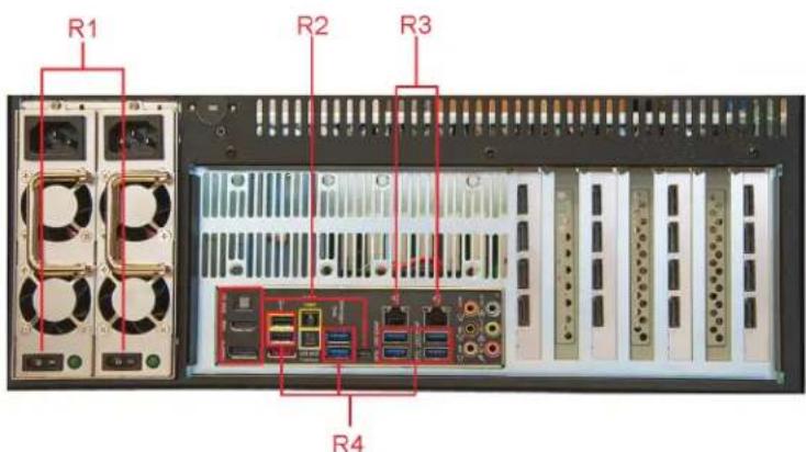
Figure 2-2. Back panel of the VWP-2040.
Table 2-3. Back panel components.
| Number in Figure 2-2 Component | |
| R1 Power Switches | |
| R2 Outputs: Mini-DisplayPort/HDMI/DisplayPort | |
| R3 Ethernet Ports | |
| R4 USB Ports | |

Figure 2-3. VWP-2040 motherboard layout.
Table 2-4. Motherboard components.
| Number in Figure 2-3 Component |
| M1 4 x DIMM, 2800(O.C) 1600 Up to 32GB |
| M2 4 x SATA3 6Gb/s ports |
| M3 6 x SATA3 6GB/s ports |
| M4 PCIe Slot 1, x16 (Gen3 x16/8 link) |
| M5 PCIe Slot 2 x16 (Gen3 x8/0 link) |
| M6 PCIe Slot 3 x16 (Gen3 x16/8 link) |
| M7 PCIe Slot 4 x16 (Gen3 x8/0 link)s |

Figure 2-4. Backplane layout of the VWP-2040.
Table 2-5. VWP-2040 backplane layout.
| Number in Figure 2-4 Rear Panel Connections | |
| 1 PS\2 Keyboard/Mouse Combo Port | |
| 2 USB 3.0 Ports | |
| 3 Optical S/PDIF Out Ports | |
| 4 Intel | ® LAN (RJ-45)port |
| 5 USB 2.0 Ports | |
| 6 External SATA Ports | |
| 7 Mini-Display Port | |
| 8 Display Port | |
| 9 HDMI Port | |
| 10 BIOS Flashback button | |
| 11 USB 2.0 Ports | |
| 12 Audio I/O Ports | |
2.5.2 VWP-2090
The VWP-2090 system incorporates the PCI Express9-G3 switched fabric backplane, providing 9 high bandwidth PCIe slots for use with any Radian Video Wall Processor video capture or graphics card. It also has SBC4, a single board computer featuring an Intel® Core i7 processor with up to 16 GB of DDR3 memory and on-board graphics.
The backplane has a single x8 lane slot (8 Gbps) and eight x4 lane slots (4 Gbps), each providing high-speed bidirectional bandwidth. This enables UHD Capture and then display UHD video on the video wall with very low latency.
Each system comes complete with high quality, server-grade hard drives with RAID 1, preinstalled with Windows 7 ^® Ultimate edition (64-bit). Enhanced system cooling is achieved via three variable speed fans, and each system offers on-board SATA and USB ports.
Because it uses PCIe switched fabrics, you can expand the VWP-2090 system using additional backplanes within VWX-2090 chassis connected via the optional expansion kit.
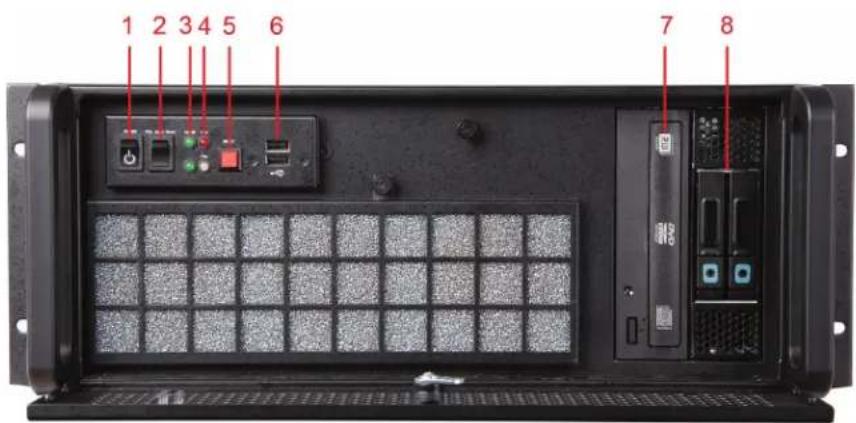
Figure 2-5. Front panel of the VWP-2090.
Table 2-6. Front-panel components.
| Number in Figure 2-5 Component | |
| 1 Power | |
| 2 PSU Alarm | Reset |
| 3 Power LED | |
| 4 HDD LED | |
| 5 Reset Button | |
| 6 USB Ports | |
| 7 DVD +RW | |
| 8 Removable | Hard Drives |

Figure 2-6. Back panel of the VWP-2090.
Table 2-7. Back-panel components.
| Number in Figure 2-6 Component | |
| R1 Power Switches | |
| R2 USB Ports | |
| R3 Ethernet Ports | |
| R4 DVI-I Output | |
2.5.3 VWP-2110
The VWP-2110 is an industrial PC incorporating an 11-slot PCIe backplane. The switched fabric technology provides 11 x 8 lane PCIe slots that have x 16 physical connectors, and each slot can provide up to 8 Gbps bidirectional bandwidth.
Each system includes a single board computer that features an Intel Core i7 processor, up to 16 GB of DDR3 memory, and on-board graphics.
You can connect multiple backplanes via the optional expansion kit.

Figure 2-7. Front panel of the VWP-2110.
Table 2-8. Front-panel components.
| Number in Figure 2-7 Component | |
| 1 Power | |
| 2 PSU Alarm | Reset |
| 3 Power LED | |
| 4 HDD LED | |
| 5 Reset Button | |
| 6 USB Ports | |
| 7 DVD +RW | |
| 8 Removable | Hard Drives |

Figure 2-8. Back panel of the VWP-2110.
Table 2-9. Back-panel components.
| Number in Figure 2-8 Component | |
| R1 Power Switches | |
| R2 USB Ports | |
| R3 Ethernet Ports | |
| R4 DVI-I Output | |
2.5.4 Video Graphics and Video Capture Cards
Your Radian Video Wall Processor is shipped from the factory with all Video Graphics and Video Capture Cards and software installed. If you want to add or change a card, refer to the card installation information in the Appendixes.
2.5.5 Cables and Adapters

Figure 2-9. Cables and adapters.
Table 2-10. Cables and adapters
| Number in Figure 2-9 Component |
| C1 DVI-VGA adapter |
| C2 DVI-Component Adapter |
| C3 DVI-HDMI Adapter |
| C4 DVI splitter cable |
| C5 Composite S-Video input cable |
| C6 Power cables |
3. Onboard Graphics Adapter
Each VWP-2040, VWP-2090, or VWP-2110 shipped by Black Box is custom built. If cards are not pre-installed, then you will need to install the software. For information on software installation, consult the softwaremanual on blackbox.com.
If you ordered Video Wall Control Software (VWS-2001), this will be installed before the VWP ships.
3.1 Video Graphics Card BIOS (VWP-2090 or VWP-2110)
The Intel x86 based architecture limits the amount of legacy I/O space available in a system to 64 KB. Hardware that requires I/O access can be mapped into this 64 KB area. A Video Graphics Card (VGC-DP-4, VGC-HD-4-D, or VGC-HD-4-H) requests 256 Bytes of legacy I/O. Any PCIe bridge will align this to a 4 KB boundary, so the I/O space allocated to each Video Graphics Card is actually 4 KB.
64 KB divided by 4 kB gives an absolute maximum of 16 Video Graphics Cards. Other system devices also require legacy I/O. Often, the Network Devices will request some I/O space, and so might the USB devices and on-board graphics. I/O space might only be available for only 8 Video Graphics Cards when installing them in a complex server class motherboard.
There are a number of different BIOS types in operation as the computer boots. The “System BIOS” is resident on the motherboard and is responsible for starting up all the hardware and mapping the resources (like the I/O) so that they are available to the CPU. The “Video BIOS” is resident on the graphics cards. It boots the CPU and informs the System BIOS which resources will be required for the CPU to operate correctly.
The System BIOS requires an I/O enabled Video Graphics Card if it is used as the boot device, i.e. it provides the graphics output that displays the BIOS boot messages. The Windows driver for the Video Graphics Card was designed so that it does not require I/O. We can use two types of Video BIOS for the Video Graphics Card, one that requests I/O (and that can be used as a boot device) and one that does not. This allows us to increase the number of Video Graphics Cards that can be used in a system.
To find out more about how to choose the correct BIOS for your requirements and how to update the BIOS for the Video Graphics Card, see Section 3.2.
3.2 Using the Onboard Graphics Adapter for the VWP-2040
3.2.1 Onboard Graphics Adapter used as Control Screen (VWP-2040)
The VWP is shipped with the BIOS configured to boot from the onboard graphics device. This output can then be used as the control screen for a typical wall configuration.
To set the system to boot on the onboard graphics device ("Internal Graphics Processing Unit" - IGPU), enter setup from the boot screen by pressing as prompted.
In the BIOS setup utility select:
Advanced Mode>System Agent Configuration>Graphics Configuration>Primary Display [IGPU]
![ASUS UEFI BIOS Utility - Advanced Mode 01/16/2015 14:36 English MyFavorite(F3) Qfan Control(F6) EZ Tuning Wizard(F11) Quick Note(F9) Hot Keys My Favorites Main Ai Tweaker Advanced Monitor Boot Tool Exit Advanced\System Agent Configuration\Graphics Configuration Graphics Configuration IGFK VBIOS Version 2180 IGPU Frequency 700 MHz Primary Display CPU Graphics CPU Graphics Memory Auto Render Standby PCIE CPU Graphics Multi-Monitor Disabled [Auto]: The primary display will be set to PCI-E when a PCI-E graphic card is detected. [CPU Graphics]: Force the primary display to be from the CPU graphics. [PCI-E]: Force the primary display to be from the PCI-E graphic cards. Hardware Monitor CPU Frequency Temperature 3200 MHz 44°C BCLK Vccr 100.0 MHz 0.944 V Ratio 32x Memory Frequency Voltage 1600 MHz 1.520 V Capacity 8192 MB Voltage +12V -5V 12.096 V 5.080 V +3.3V 3.328 V Last Modified ExMode(F7)→ Version 2.16.1240. Copyright (C) 2014 American Megatrends, Inc.](/content/2026/05/1069312/images/fa7ccad476310142ac3c868e14ddf9ba554ec1d942bf87ed09052d88cd52aea8.jpg)
Figure 3-1. VWP-2040 control screen.
3.2.2 Onboard Graphics Adapter Disabled (VWP-2040)
If you do not require a control screen, then you should disable the integrated graphics as described below.
-
Connect a monitor to the onboard graphics device output and enter setup from the boot screen by pressing
as prompted. -
In the BIOS setup utility select:
Advanced Mode>System Agent Configuration>Graphics Configuration>Primary Display [PCIE]
- If the onboard graphics is disabled, a PCIe graphics device should be installed in slot 1 on the motherboard. Slot 1 is located nearest to the CPU.
3.3 Onboard Graphics Adapter for the VWP-2090 or VWP-2110
3.3.1 Onboard Graphics Adaptor used as Control Screen (VWP-2090 or VWP-2110)
The VWP-2090 or VWO-2110 is shipped with the BIOS configured to boot from the onboard graphics device. This output can then be used as the control screen for a typical wall configuration.
To set the system to boot on the onboard graphics device ("nitiate Graphic Adapter" - IGD), enter setup from the boot screen by pressing
In the BIOS setup utility select:
Advanced>Graphic Configuration>Graphics Configuration>Primary Display Selection>Initiate Graphic Adapter - [IGD]

Figure 3-2. VWP-2090 or VWP-2110 Control screen.
3.3.2 Onboard Graphics Adaptor Disabled (VWP-2090 or VWP-2110)
If you do not require a control screen, then you should disable the integrated graphics as described below.
Connect a monitor to the onboard graphics device output and enter setup from the boot screen by pressing
In the BIOS setup utility select:
Advanced>Graphic Configuration>Graphics Configuration>Primary Display Selection [PEG/PCI]
Once the Primary Display selection PEG/PCI has been made, the "Above 4GB MMIO BIOS assignment" should be disabled.
Navigate to:
Advanced>Graphic Configuration>PEG Port Configuration> Above 4GB MMIO BIOS assignment - Disabled
By opting to disable the on board graphics adapter, this reduces the maximum number of screens available from 64 to 32.
![Phoenix SecureCore Technology Setup Advanced Graphic Configuration ► DMI Settings ► Intel(R) UT for Directed I/O (VT-d) ► Graphics Configuration ► PEG Port Configuration Cpu Audio Device (D0:D3:F0) CHAP Device (D0:D7:F0) Thermal Device (D0:D4:F0) CRID support Above 4GB HDMI BIOS assignment [Enabled] [Disabled] [Disabled] [Disabled] [Enabled] Disabled Enabled Enable/Disable above 4GB Memory MappedIO BIOS assignment F1 Help F1 Select Item +/- Change Values F3 Setup Defaults Foc Exit ** Select Menu Enter Select ▶ Sub-Menu F18 Save and Exit](/content/2026/05/1069312/images/22fab5aed22933f77005ba64f8cd50d6b28087627c61a46690d4d1d4f8faa24b.jpg)
Figure 3-3. Disable onboard graphics adapter screen (VWP-2090 or VWP-21110).
The system will then boot from an output from the graphics card identified last by the PCI Bus.
4. Hardware Installation
4.1 V WP-2040
Your VWP-2040 arrives with all necessary cards installed. If you want to add more cards, refer to the Appendixes in this manual for installation instructions.
4.2 VWP-2090 Backplane Layout
Your VWP-2090 may have cards that require installation because cards may have been shipped separately.
To ensure your cards are installed correctly, consult the appendixes in this manual for detailed instructions.
VWP-2090 Backplane Layout
The VWP-2090 is fitted with the G3 backplane. The backplane consists of:
- One PICMG1.3 slot
- One x8 lane PCIe slot
• Eight x4 lane PCIe slots

Figure 4-1. VWP-2090 backplane layout.
Table 4-1. VWP-2090 PCIe port width.
| Slot Port Width | |
| PICMG X8 | |
| Slot 1 X8 | |
| Slot 2 X4 | |
| Slot 3 X4 | |
| Slot 4 X4 | |
| Slot 5 X4 | |
| Slot 6 X4 | |
| Slot 7 X4 | |
| Slot 8 X4 | |
| Slot 9 X4 |
Table 4-2. VWP-2090 backplane components.
4.3 Connecting the VWX-2090 Expansion Chassis to the VWP-2090 Radian Video Wall Processor Chassis
You can connect a VWX-2090 expansion chassis to the VWP-2090 to increase the number of PCIe slots available.

Figure 4-2. Connect the expansion chassis.
Connect the chassis to the expansion chassis via the appropriate cable.
The cards are factory installed into a system as a pair. When connecting expansion chassis ensure that the pair labelled Link1 are connected using an approved cable, the pair labelled Link2 are connected together, and so on. If this is not possible, connect the expansion chassis to the host machine and re-install the driver to reset the pairings.

natural_image
Electronic components including a green PCI board, a black cable with connector, and an inset photo of a RAM card with LED lighting (no text or symbols on main components)Figure 4-3. Pre-installed cards and appropriate cable to link them together.
When connecting a VWX-2090 expansion chassis to a VWP-2090 machine, the appropriate card is pre-installed in the VWX-2090 x8 slot. The appropriate card in the VWX-2090 is pre-installed in the PICMG1.3 SBC slot.
VWP-2090 and VWX-2090 LED indicators.
The VWP-2090 and VWX-2090 have an LED for each PCIe slot and the PICMG1.3 SBC slot.
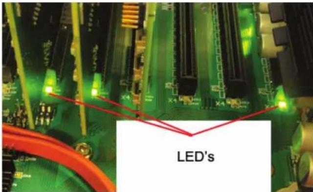
Figure 4-4. LEDs on the VWP-2090 and VWX-2090.
Table 4-3. LEDs on the VWP-2090 and VWX-2090.
| LED Description |
| LED1 ON = +5V Standby Voltage present |
| LED2 ON = +5V supply present |
| LED3 ON = +12V supply present |
| LED4 ON = +3.3V supply present |
| LED5 ON = PICMG link speed = G3, FLASH-FAST = G2, FLASH-SLOW = G1 |
| LED7 ON = PCIe Slot 1 link speed = G3, FLASH-FAST = G2, FLASH-SLOW = G1 |
| LED9 ON = PCIe Slot 2 link speed = G3, FLASH-FAST = G2, FLASH-SLOW = G1 |
| LED10 ON = PCIe Slot 3 link speed = G3, FLASH-FAST = G2, FLASH-SLOW = G1 |
| LED11 ON = PCIe Slot 4 link speed = G3, FLASH-FAST = G2, FLASH-SLOW = G1 |
| LED12 ON = PCIe Slot 5 link speed = G3, FLASH-FAST = G2, FLASH-SLOW = G1 |
| LED13 ON = PCIe Slot 6 link speed = G3, FLASH-FAST = G2, FLASH-SLOW = G1 |
| LED14 ON = PCIe Slot 7 link speed = G3, FLASH-FAST = G2, FLASH-SLOW = G1 |
| LED15 ON = PCIe Slot 8 link speed = G3, FLASH-FAST = G2, FLASH-SLOW = G1 |
| LED16 Not Used |
NOTE: No LEDs flashing indicates that lane width has not been established. The LEDs will not flash on slots where no cards are installed.
4.4 VWP-2110 Backplane Layout
Your VWP-2110 may have cards that require installation because cards may have been shipped separately.
To ensure your cards are installed correctly, consult the appendixes in this manual for detailed instructions.
VWP-2110 Backplane Layout
The VWP-2110 is fitted with the G3 backplane. The backplane consists of:
- One PICMG1.3 slot
• Eleven x8 lane PCIe slot

Figure 4-5. VWP-2110 Backplane Layout.
Table 4-4. VWP-2110 PCIe port width.
| Slot Port Width | |
| PICMG X8 | |
| Slot 1 X8 | |
| Slot 2 X8 | |
| Slot 3 X8 | |
| Slot 4 X8 | |
| Slot 5 X8 | |
| Slot 6 X8 | |
| Slot 7 X8 | |
| Slot 8 X8 | |
| Slot 9 X8 | |
| Slot 10 X8 | |
| Slot 11 X8 | |
Table 4-5. VWP-2110 backplane components.
4.5 Connecting the VWX-2110 Expansion Chassis to the VWP-2110 Radian Video Wall Processor Chassis
You can connect a VWX-2110 expansion chassis to the VWP-2110 to increase the number of PCIe slots available.
The following diagram illustrates how this can be achieved.

flowchart
graph TD
    A["Main Chassis"] --> B["Chassis Block 1"]
    A --> C["Chassis Block 2"]
    A --> D["Chassis Block 3"]
    A --> E["Chassis Block 4"]
    A --> F["Expansion Chassis"]
    B --> G["Final Chip"]
    C --> G
    D --> G
    E --> G
    F --> G
Figure 4-6. Expansion chassis setup.
The Radian Video Wall Processor technology allows multiple backplanes to be arranged in a star configuration, providing the ability to create very large systems consisting of several chassis, each with 11 available slots for video capture inputs and/or graphics outputs, connected via the optional expansion kit.
Connect the chassis to the expansion chassis via the appropriate cable.
The cards are factory installed into a system as a pair. When connecting expansion chassis ensure that the pair labelled Link1 are connected using an approved cable, the pair labelled Link2 are connected together, and so on. If this is not possible, connect the expansion chassis to the host machine and re-install the driver to reset the pairings.

natural_image
Three electronic circuit boards with connectors and a black cable, shown from different angles (no text or symbols visible)Figure 4-7. Pre-installed cards and appropriate cable to link them together.
When connecting a VWX-2110 expansion chassis to a VWP-2110 machine, the appropriate card is pre-installed in the VWX-2090 x8 slot. The appropriate card in the VWX-2090 is pre-installed in the PICMG1.3 SBC slot.
If your Radian Video Wall Processor Chassis does not arrive from the factory fully populated with cards, refer to the Appendixes for diagrams and installation instructions for each available card option that can work with the Chassis.
V WP-2110 LEDs
The VWP-2110 and VWX-2110 have an LED for each PCIe slot and the PICMG1.3 SBC slot.

Figure 4-8. VWP-2110 and VWX-2110 LEDs.
Table 4-6. VWP-2110 and VWX-2110 LEDs.
| LED Description |
| D1 ON = +12V supply present |
| D2 ON = +3.3V supply present |
| D3 ON = +5V supply present |
| D4 ON = +5V Standby supply present |
| D5 ON = PICMG link speed = G3, FLASH-FAST = G2, FLASH-SLOW = G1 |
| D6 ON = PCIe Slot 1 link speed = G3, FLASH-FAST = G2, FLASH-SLOW = G1 |
| D7 ON = PCIe Slot 2 link speed = G3, FLASH-FAST = G2, FLASH-SLOW = G1 |
| D8 ON = PCIe Slot 3 link speed = G3, FLASH-FAST = G2, FLASH-SLOW = G1 |
| D9 ON = PCIe Slot 4 link speed = G3, FLASH-FAST = G2, FLASH-SLOW = G1 |
| D10 ON = PCIe Slot 5 link speed = G3, FLASH-FAST = G2, FLASH-SLOW = G1 |
| D11 ON = PCIe Slot 6 link speed = G3, FLASH-FAST = G2, FLASH-SLOW = G1 |
| D12 ON = PCIe Slot 7 link speed = G3, FLASH-FAST = G2, FLASH-SLOW = G1 |
| D13 ON = PCIe Slot 8 link speed = G3, FLASH-FAST = G2, FLASH-SLOW = G1 |
| D14 ON = PCIe Slot 9 link speed = G3, FLASH-FAST = G2, FLASH-SLOW = G1 |
| D15 ON = PCIe Slot 10 link speed = G3, FLASH-FAST = G2, FLASH-SLOW = G1 |
| D16 ON = PCIe Slot 11 link speed = G3, FLASH-FAST = G2, FLASH-SLOW = G1 |
| D17 ON= PLX Fatal Error |
| D24 ON = PSU FAULT |
5. Software Overview
Each Radian Video Wall Processor is custom built. If cards are not pre-installed, then you will need to install software/drivers. For information on software installation, consult the relevant user manual on blackbox.com.
If you ordered VWS-2001 Video Wall Controller Software, it will be installed prior to shipment.
5.1 V W S -2001
VWS-2001 is a software application used to control Radian Video Wall Processor, IP-Camera and third-party application windows on Radian Video Wall Processor machines. It provides a graphical representation of the video wall and a toolbar through which you can manipulate all available sources and applications. Wall Control can be used to interactively open, move, size, and position any window on either the local machine or a remote network client machine.
Wall Control features include:
Video Wall Controller and IP Camera Window Control
Control Video Wall Controller and IP Camera* windows on the video wall including the window properties and settings; position, size, aspect ratio. Customize window on screen display caption, control data transfer, and scaling.
* Requires IP camera support.
Application Control
A built in application server that provides support for controlling third party applications such as Microsoft® Internet Explorer, DGCPlay, MS Paint, and Notepad.
Intuitive User Interface
A standardized set of property sheets that provide a user-friendly interface for each type of window.
On Screen Display (OSD)
Highly flexible and highly configurable OSD for over laying text and bitmaps* over Video Wall Controller and IP Camera windows offering the ability to add text descriptions and logos*. OSD also supports input for displaying specific variables such as frame rate, etc.
* This feature may not be available on some types of windows.
Remote Control
You can operate Wall Control remotely on any PC/laptop via a local network connection.
Layout and Offline Support
You can use layout files to save and recall specific window configurations, including window size and positions on the video wall. You can save and restore all configurable window properties using layout files. You can also edit previously exported configuration files offline using the Wall Control offline function. This enables you to edit files from a mobile device (for example, a laptop), then import the files into Wall Control.
Command-Line Interface
Wall Control has a powerful Command-Line Interface to automate almost any operation including opening layout files, changing input settings, and moving and maximizing individual windows. The Command-Line Interface can also be started from batch files enabling automation at specific times.
Audio Support
Both digital and analog audio are supported for Video Wall Controller windows, depending on the Video Capture Card installed in the system. Audio support allows the configuration of embedded digital and analog audio capture inputs.
Carousel
When configured, the Carousel function automatically cycles through lists of different Video and IP camera inputs at set time intervals.
Video Wall Screen Order
The Screen Order function is used to configure the order in which screens appear on the desktop. This allows the screen order to be changed without physically swapping any of the output cables between graphics cards.
RS-232 and TELNET Support for Crestron/AMX Controllers
Control the video wall remotely from a Crestron®/AMX® controllers with access to the full, local Command-Line Interface. This includes support for RS-232 (via serial cable) and TELNET (via local network).
Multi-Language Support
VWS-2001 software is available in the following languages: English (USA and UK), French, Spanish, German, Polish, Simplified Chinese, Russian, and Japanese.
All Wall Control functions are covered in detail in the online help.
5.2 Video Capture Card Software
All Video Capture Cards include a powerful software application that you can use to configure the format of the input sources and display the data.
Video Streaming
DirectShow ^® drivers for WDM Streaming driver support the following applications, to encode, record, and stream video over networks or the Internet:
- Microsoft Media Encoder
• VLC - VirtualDub
- Any other DirectShow encoding software
For streaming applications, you can use Video Capture Cards with Windows Media Encoder to compress and stream captured video. To replay the video, use Windows Media Player.
Any application compatible with Windows DirectShow technology can use the Video Capture Cards' built-in WDM support.
Video Capture Cards Software Capabilities
- Timestamp support for streaming synchronization.
- Synchronization of multiple inputs across multiple cards.
- Synchronize systems using network clock synchronization.
- Use for edge blending and other applications.
Flexible and configurable EDID Management:
- Allows programming of custom EDID parameters for capture cards.
- Low Input to Output Capture Latency.
- DMA to third party graphics vendors back and front buffers via Direct3D.
- Compatibility with AMD DirectGMA.
- Compatibility with Nvidia GPUDirect.
-
User Mode filter for source selection.
-
Enables cropping support in DirectShow on all inputs.
- Supports Start and Stop trigger interface on all Video Capture Card inputs.
Unified Video Capture Cards Driver
- Multiple cards per system, 16 streams per input.
• Frame sync and time stamping. - DirectShow interface.
- The RGBEasy API for advanced audio and video control.
- Fully integrated for use with Video Wall Controller software for video wall applications.
Multistream
The MultiStream feature is available on all Video Capture Cards and enables multiple independently formatted video streams to be set up in parallel.
Each stream can be formatted completely independently, and individual selection of resolution, color space, and cropping region can be set for each stream. This maximizes bandwidth use of the capture card PCIe interface, and also simplifies development tasks for application developers who do not need to implement video stream reformatting separately.
6. Filter Maintenance (VWP-2090 or VWP-2110)
If your Radian Video Wall Processor Chassis does not arrive from the factory fully populated with cards, refer to the Appendixes for installation instructions for each available card option that can work with the Chassis.
The system filter is an integral part of the wall controller—maintain it correctly. If you don't maintain the filter, the system might overheat and fail. In normal operating conditions, you should remove and clean the filter every 3 months. This 3-month period is a guide only; you can increase it to every 6 months or decrease it to one month depending on the levels of dust in the environment the system is operating in.
We recommend checking the condition of the filter at regular intervals.
The filter can be removed and cleaned while the system is operating; you do not have to shut down your system.
NOTE: Failure to maintain the system filter could result in damage to your system and invalidate the warranty.
Remove the Filter
Open the front panel door and locate the filter housing screw, remove the screw, and lift the filter housing away from the front panel.
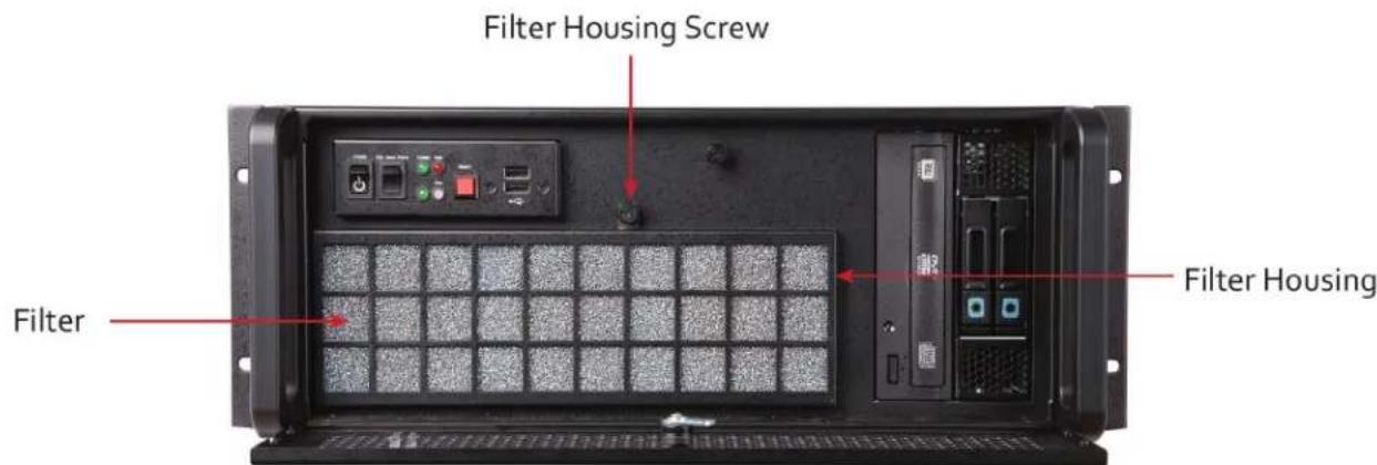
Figure 6-1. Filter location on the VWP-2090 or VWP-2110.
Remove the filter from the housing and shake it to remove any dust particles, far away from the system to so it doesn't absorb the dust. You can use a vacuum cleaner to clean the filter.
NOTE: Do not immerse the filter in water or any other cleaning liquid.
For advice on replacement filters, contact Black Box Technical Support at 877-877-2269 or info@blackbox.com.
Appendix A. Installing the Video Graphics Card (VGC-DP-4, VGC-HD-4-D, or VGC-HD-4-H)
Table A-1. Video Graphics Cards
| Video Graphics Cards | ||
| Product Code Outputs Signal Format | ||
| VG C-D P-4 4-port DisplayPort graphics card DisplayPort | ||
| VGC-HD-4-D | 4-port DisplayPort graphics card with DVI adapters | DisplayPort, DVI |
| VGC-HD-4-H | 4-port DisplayPort graphics card with HDMI adapters | DisplayPort, HDMI |
A.1 Introduction
The Video Graphics Card is based upon a single, powerful graphics processor that is complemented by faster memory and higher pixel transfer bandwidth over its 16-lane second generation PCIexpress interface. Up to sixteen Video Graphics Cards can be supported by the Radian Video Wall Processor display driver, providing flexible system configurations for up to 64 screens.
- DisplayPort connectors can link to full-size, locking cables capable of driving next generation displays.
• DVI support using DVI adapters (powered via graphics card). - Up to 128 feet (40 meters) cable support using extender modules (powered by a graphics card).

natural_image
Close-up of a green PCI card with multiple Ethernet ports and a solar panel on top (no visible text or symbols)Figure A-1. Video Graphics Card illustrated.
A.2 Features
The Video Graphics Card supports the display of digital video capture windows. It is ideal for high-end video/data walls, signage, or display wall applications.
- Gen 2, x16 lane PCIexpress graphics card.
• Digital outputs up to 4 x 2560 x 1600 x 32 bits/pixel @ 60 Hz.
- Low power.
• High Performance 2D and 3D graphics.
• High performance DMA image load (up to 2 GB/s).
- Support for Windows Server 2008, and Windows 7 (Server 2008 or Windows 7 64-bit (required for greater than 8 screens support).
- RGB, SD, and HD video window support by adding the Video Capture Cards.
- Up to 16 cards per system for a maximum of 64 displays. To use three or more Video Graphics Cards, you must use a system based on the VWP-2090 or VWP-2110.
This section explains how to install Video Graphics Cards and spread the Windows desktop across all the screens. If you plan to use the Video Graphics Cards with other Video Wall Controller products, follow this section to get the Windows desktop working correctly first.
System Requirements
- A Pentium® PCIExpress bus computer with sufficient free PCIe slots.
- At least 1 GByte of RAM.
- Windows Server 2008, Windows 7 (Server 2008 or Windows 7 64-bit required for greater than 8 screen support).
Unpacking
Your package should contain the following items:
• The Video Graphics PCIe plug-in card.
• (1) DVD containing the software image.
A.3 Installing the Video Graphics Card
We recommend that you install all Video Graphics Cards and all Video Capture Cards in the system before installing the drivers. Otherwise, you may need to reinstall the drivers as the card's PCI bus numbers change.
NOTE: All plug-in cards are static-sensitive and packed in antistatic materials. Keep the card in its packaging until you are ready to install.
We recommend that you do not discard the packing box until you are completely satisfied with the Video Graphics Card, and it is fully installed and working correctly. We also recommend that you note the serial number of the card in a prominent place before you plug the card into the computer. This should hasten any query if you need to contact Black Box Technical Support. The serial number is displayed on the card and the box label.
- Power down the PC (including peripherals), switch power off, and disconnect all the cables connected to the computer, noting the positions for accurate reconnection. Remove the PC cover.
- Locate a vacant PCIe (x4 or above) slot for the Video Graphics Card on the motherboard and remove the backing plate (retain all screws). If in doubt, consult your motherboard documentation to correctly identify a PCIe (PCIexpress) slot. If you force the card into a 32- or 64-bit PCI or PCI-X slot, it will be irreparably damaged when the system is powered up and the warranty will be void.
- Remove the card from its packaging and secure it firmly into the empty PCIe slot. Be careful when securing the card into the slot because some motherboards may have components that impede the siting of the card.
- Screw the card bracket to the back panel of the PC and replace the cover.
- Connect screens to all the outputs from the card. If there are other graphics devices in the system, connect screens to them (even if you don't intend to use all the outputs in your final configuration).
- Switch all the screens on then switch the machine on. You should see the boot messages on one of the screens. The screen on which the system will boot depends on how the system is configured and the motherboard BIOS. You cannot control which of the Video Graphics Card outputs the system will boot on.
A.3.1 Installing the Display Drivers
- Once the Video Graphics Card has been installed and the boot messages are appearing on the correct monitor, you can start Windows.
- Boot the system into Safe Mode then Log on as a user with administrative access rights.
- The Found New Hardware Wizard will announce that new hardware has been found.
NOTE: Do not use the Found New Hardware Wizard to install the Video Graphics Card drivers.
- Install the display drivers from the Software Installation Suite DVD supplied with the Video Graphics Card.
- If your final configuration has less than four screens, select the number of screens required; otherwise, select four screens.
- Restart the machine.
- When Windows starts up, the desktop should spread over all the screens connected to the Video Graphics Card.
A.3.2 Installing Additional Video Graphics Cards
As the number of required screens increase, the likelihood of reaching a system limitation or encountering a problem increases. The system limitations are the amount of address space available and the capacity of the power supply.
Consult Black Box Technical Support at 877-877-2269 or info@blackbox.com if you have any problems installing multiple cards.
The amount of current a power supply can deliver on each voltage rail is limited. There may also be a limit on the total power.
Each Video Graphics Card requires 0.25 A at +3.3 V and 1.2 A at +12 V.
You can calculate the amount of current and the amount of power required for the Video Graphics Cards. For example, the requirements for a 24-screen system of Video Graphics Cards is calculated as follows:
Current:
- Six Video Graphics Cards (each with four connectors) running on current equaling +3.3 V each card requires 6 x 0.25 A = 1.5A.
- Six Video Graphics Cards (each with four connectors) running on current equaling +12 V each card requires 6 x 1.2A = 7.2A.
Power
$$ (3. 3 \mathrm{V} \times 1. 5 \mathrm{A}) + (1 2 \mathrm{V} \times 7. 2 \mathrm{A}) = 9 1. 3 5 \mathrm{W} $$
These are the requirements for the Video Graphics Card; you must take into account the requirements of all the other devices in the system.
A.4 Video Graphics Card Video BIOS
The Intel x86 based architecture limits the amount of legacy I/O space available in a system to 64 KB. You can map hardware that requires I/O access into this 64 KB area. A Video Graphics Card requests 256 Bytes of legacy I/O. Any PCIe bridge will align this to a 4 KB boundary, so the I/O space allocated to each Video Graphics Card is actually 4 KB.
64 KB ÷ 4 KB gives an absolute maximum of 16 Video Graphics Cards. Other system devices also require legacy I/O. Often the Network Devices will request some I/O space, and so might the USB devices and on-board graphics. It is not unusual for there to be I/O space available for only 8 Video Graphics Cards when installing them in a complex server-class motherboard.
There are a number of different BIOS types in operation as the computer boots. The “System BIOS” is resident on the motherboard and is responsible for starting up all the hardware and mapping in the resources (like the I/O) so that they are available to the CPU. The Video BIOS is resident on the graphics cards. It boots the GPU and informs the System BIOS which resources will be required for the CPU to operate correctly.
The System BIOS requires an I/O-enabled Video Graphics Card if it is used as the boot device; i.e. it provides the graphics output that displays the BIOS boot messages. The Windows driver for the Video Graphics Card does not require I/O. We can use two types of Video BIOS for the Video Graphics Card, one that requests I/O (and that can be used as a boot device) and one that does not. This allows us to increase the number of Video Graphics Cards that can be used in a system.
To find out more about how to choose the correct BIOS for your requirements and how to update the BIOS for the Video Graphics Card, see Chapter 3.
A.5 Card Ordering
To connect up to 64 screens to Video Graphics Cards, configure the links as shown in the diagram below.

Figure A-2. Card numbering on the link header.
The links control the order in which the display driver uses the Video Graphics Cards. Knowing the order that the Video Graphics Cards use will help when connecting the screens and the outputs from video switches.
NOTE: If you have not configured your system to boot on an on-board VGA graphics device or another plug-in VGA card, the system will boot on the master head of one of the Video Graphics Cards, but it is not possible to control which output will be used—this depends on the motherboard BIOS.
- Insert the Video Graphics Cards into the PCIe slots.
- Connect the screens to the cards. The first card should be connected to the first group of four screens; the second should be connected to the second group of four screens and so on.
- Switch the screens on then switch the machine on.
- Log on as a user with administrative access rights.
- The Found New Hardware Wizard will announce that new hardware has been found. This will happen once for each slave Video Graphics Card you have added to the system. Do not use the Found New Hardware Wizard to install the Video Graphics Card drivers.
- The Windows desktop should appear on the four screens attached to the first card as it did after the display driver was installed for the first Video Graphics Card.
- You need to install the display driver again. This time you should specify the number of screens you wish to use.
- Restart the machine.
The Windows desktop will now spread across the number of screens you specified.
DisplayPort Outputs
The Video Graphics Card has four DisplayPort connectors that allow full-size, locking cables capable of driving next generations displays. When used in conjunction with the extender modules (powered via the Video Graphics Card), cable lengths of up to 96 feet (30 meters) can be achieved.
The Video Graphics Card outputs are numbered as follows:

Figure A-3. Video Graphics Card outputs.
A.6 Multi-Screen Configuration
To change the display settings for the Video Graphics Cards, use the Display Properties dialog in the Control Panel.
Display: 2. (Default Monitor) on Video Graphics Card (example only; this is a dropdown menu box)
Resolution: 5120 x 4096 (example only; this is a dropdown menu box)
Multiple displays: Extend desktop to this display. (example only; this is a dropdown menu box)
Make this my main display. (example only; this is a checkbox)
Figure A-4. Display Properties example screen parameters.
If you have more than one graphics device in your machine, the Display Settings allow you to control which graphics devices are used and what their position on the desktop is. There should be a single monitor icon representing all of the Video Graphics Cards and a monitor icon for each additional graphics device in the system (there is a limit to the number of monitor icons that are displayed).
To change other properties of the Video Graphics Card display, select the Video Graphics Card monitor icon, click on the Advanced settings and go to the TWIN tab.

Figure A-5. Monitor Configuration screen.
Resolution per Screen:

Figure A-6. Resolution per screen slider bar.
NOTE: Changing the resolution may alter the color palette settings, so check that it is correct before clicking OK or Apply.
Color Palette:
Select the number of colors you want to use.
Refresh Rate:
Use the drop-down arrow to select a refresh rate for the desktop. Only the refresh rates available at the selected resolution and color depth are displayed. The maximum settings are restricted to the capabilities of the screens connected to the system.
Source of Mode:

Figure A-7. Source of Mode screen.
When the TWIN tab is selected, the display driver reads the EDID information from each monitor and reads the Registry to find detailed display timing information.
The Source of Mode group box shows which mode sources are available for the selected resolution and color depth.
The Source of Mode has 4 options.
- Default: Monitor timing information from the display driver's internal tables.
- Custom: Monitor timing information from the Registry (See Defining Custom Modes for details).
• Monitor (Master): Monitor attached to output 1 of the Master Video Graphics Card is used for all outputs.
• Monitor (Each): The monitor timing information from each monitor is used for the output connected to that monitor.
No. Screens
Change the number of screens the display driver uses. You should always install the driver (using install.exe) for the maximum number of screens you want to use.
Screen Arrangement:
Use the drop-down menu to select the type of screen arrangement you require. The illustration in the Monitor Configuration box will reflect your choice.
Force DVI Output:
If set, Force DVI Output limits the display modes available to those displayable via Single-Link DVI (165MHz).
If clear, this allows display modes greater than 165 MHz, for example 2560 x 1600 @ 60 Hz.
Prune Modes:
Enabling this check box limits the resolutions displayed in the resolution box to those that are supported by all of the screens attached to the Video Graphics Card's active outputs. This information is read from the monitor EDIDs when the TWIN tab is opened. If the state of this check box is changed, then the resolution control is updated.
When you click on OK or Apply, the following dialog is displayed.
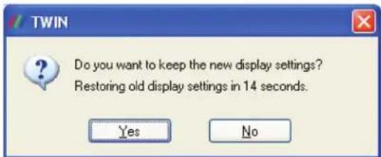
Figure A-8. TWIN dialog box.
This dialog gives you the option to accept the changes or restore the previous display settings. The display will return to the previous settings after 15 seconds if you do not select Yes or No.
CAUTION: Always close all video window applications (including Wall Control applications connected locally or remotely to the system) before performing any operation that modifies the settings of any attached display. Failure to do so could result in the machine locking up and requiring a reboot.
A.7 Defining Custom Modes
To define custom modes, use the Custom Mode Utilities tool on the Radian Video Wall Processor thumb drive. You can also download the latest version from the Black Box website: www.blackbox.com
The Custom Modes tool is a utility for defining custom modes that can be generated by the Video Graphics Card. The custom modes tool must be used on a system where the active display driver supports custom modes. To generate a custom mode, you must enter the following values into the utility application dialog box:
- X Resolution—The active display width in pixels.
- Y Resolution—The active display height in lines.
- Horizontal Front Porch—The horizontal front porch in pixels.
- Horizontal Sync Width—The H-Sync width in pixels.
- Horizontal Back Porch—The horizontal back porch in pixels.
• Vertical Front Porch - The vertical front porch in lines. - Vertical Sync Width—The v-sync width in lines.
- Vertical Back Porch—The vertical back porch in lines.
- Horizontal Sync Polarity—0 = negative, 1 = positive.
- Vertical Sync Polarity—0 = negative, 1 = positive.
- Refresh—The refresh rate displayed in the Display Properties dialog. Also used for calculating the dot-clock if no value is provided.
- Dot Clock (optional)—The pixel dot-clock in KHz. This is calculated from the Refresh rate if not provided.
NOTE: If a new mode is created or an existing one is amended, you must close the Display Properties dialog and re-open it to ensure the new values are refreshed in the display driver.
A.8 Screen Order
Connecting Screens
The first card to be initialized generates the picture for the top left monitor in the wall of screens, plus the three adjacent screens. The second card drives the next four screens and so on. This sounds simple, but can be confusing when trying to determine how to assign monitor video cables to the Video Graphics Card outputs.
Changing the Order of the Screens
To change the order in which the screens appear, use the Wall Control application.
Select Screen Order from the Wall Control Configure menu and in the displayed dialog, click on the screens sequentially to establish the order you want.
NOTE: The new screen order will not be applied until the Wall Control server is re-booted.
Appendix B. Installing the Video Capture Cards
The available Video Capture Cards and their connectors are listed in Table B-1. Sections B.1 through B.9 provide installation instructions for each Video Capture Card.
Table B-1. Video Capture Cards
| Product Code Connectors Supported Inputs | ||
| VCC-SD-HD-A-2 (1) | DVI-I, (1) RCA (female) on main board, (1) HD15 (male) on audio board | HDMI, DVI, VGA/YPbPr |
| VCC-SD-HD-3 (2) DVI-I, (1) RCA (female) HDMI, DVI, VGA/YPbPr, | Composite Video, Audio Capture | |
| VCC-SDI-SD-HD-3 (1) | DVI-I, DVI, HDMI, Component, and RGB (VGA) inputs using adapters, (1) RCA (female), (1) BNC | HDMI, DVI, VGA/YPbPr |
| VCC-HD-4 (2) DMS59 high-density video connectors Analog RGB, DVI single-link mode, | HD mode | |
| VCC-DP-2 | (2) Locking DisplayPort 1.2 connectors | DisplayPort 1.2 |
| VCC-HD-4-H | (2) DSM59 connections plus adapters | (4) HDMI, (2) HDMI splitter cables |
| VCC-HD-4-D | (2) DSM59 connectors plus adapters | (4) HDMI, (2) DVI splitter cables |
| VCC-SDI-4 | (4) BNC | (4) SDI |
| VCC-STREAM | (2) RJ-45 Ethernet ports, (1) DisplayPort output connector | (2) Ethernet (LAN1, LAN2) |
B.1 Video Capture Card (VCC-SD-HD-A-2): (1) HD channel
+ (1) SD channel + AM2 + cable, full height

natural_image
Green PCI expansion card with various ports and connectors (no visible text or labels)Figure B- 1. Video Capture Card (VCC-SD-HD-A-2) illustrated.
B.1.1 Introduction
The Video Capture Card (VCC-SD-HD-A-2) has two independent video capture channels—one supporting HD capture and a second simultaneously decoding Standard Definition composite video. The VCC-SD-HD-A-2 also adds analog and HDMI audio capture, which can be perfectly synchronized with either video capture channel.
Features include:
- A single card solution for distance learning, lecture capture, and web casting.
- Viewing analog or DVI sources from a wide range of PCs, MACs, Industrial/Medical equipment, cameras and other video equipment.
- Videoconferencing.
- DirectShow drivers for WDM Streaming driver supports the following applications to encode, record, and stream video over networks or the Internet:
- Windows Media Encoder®
- VLC
- StreamPix
- VirtualDub
- Adobe Flash Encoder
- AMCap
- Any other DirectShow encoding software
B.1.2 Hardware Overview
Dual Channel Video
• Channel 1: Digital or Analog HD Video
• Channel 2: Composite Video
Flexible Audio Capture
• Balanced (XLR) and Unbalanced (RCA) from optional module
• HDMI audio through HD Video Channel
Video Capture Card Driver
- Multiple cards per system, 16 streams per channel
• Frame sync and time stamping - Direct Show interface
- RGBEasy API
B.1.3 What's Included
Your packing box should contain the following items:
• (1) Base Video Capture Card
• (1) Audio Module Card
• (1) Full height bracket fitted to base card
• (1) audio breakout cable
• (1) DVI/VGA adapter
• (1) DVI/Component adapter
• (1) DVI/HDMI adapter
- DVD with software
All plug-in cards are static-sensitive and are packed in anti-static material. Keep the card in its packaging until you are ready to install.
We recommend that you do not discard the packing box until you are completely satisfied with the Video Capture Card and it is fully installed and working correctly. We also recommend that you note the serial number of the card in a prominent place before the card is plugged into the computer. This should hasten any query if you need to contact Black Box Technical Support. The serial number is displayed on the card itself and the box label.
B.1.4 Installing the Video Capture Card (VCC-SD-HD-A-2)
You are likely to need a flat blade and/or a cross-head screwdriver to install the card; it would be useful to have these on hand before you begin.
- Power down the PC (including peripherals), switch off the main power, and disconnect all the cables connected to the computer, noting the positions for accurate reconnection.
- Remove the PC cover.
- For the VCC-SD-HD-A-2 video capture card, locate a vacant PCI Express slot (x4 or higher) on the motherboard and remove the blanking plate (retain all screws).
CAUTION: If you are in doubt, consult your motherboard documentation to correctly identify a PCI Express slot. If the card is forced into a 32 or 64 bit PCI or PCI-X slot it, will be irreparably damaged when the system is powered up, and the warranty will be void. - Reconnect all cables to the PC, then connect a DVI cable (not supplied).
- A standard definition signal can be connected to the RCA connector on the VCC-SD-HD-A-2.
- An Audio feed can be connected to the Audio Module via the Audio Breakout Cable.
- Power up the PC and install the software.
B.1.5 How to Connect Input Sources
The VCC-SD-HD-A-2 card has one DVI-I and one RCA (female) connector, and one RGB (male) connector on the Audio Module: The DVI-I connector supports DVI, HDMI, Component and RGB (VGA) inputs using the supplied adapters where required. A DVI input is connected directly into the DVI-I connector which accepts DVI-D (digital) or DVI-A (analog) inputs.

Figure B-2. DVI input.
An HDMI input is connected to the DVI-I connector using the supplied DVI-HDMI Adapter.

A Component input is connected to the DVI-I connector using the supplied DVI-Component Adapter.

flowchart
graph LR
    A["DVI-I Connector"] --> B["DVI-Component Adapter"]
    B --> C["Component Input"]
    style A fill:#f9f,stroke:#333
    style B fill:#ccf,stroke:#333
    style C fill:#dfd,stroke:#333
Figure B-4. Component input.
An RGB (VGA) input is connected to the DVI-I connector using the supplied DVI-VGA Adapter:

flowchart
graph LR
    A["DVI-I Connector"] --> B["DVI-VGA Adaptor"]
    B --> C["RGB (VGA) Input"]
Figure B-5. RGB (VGA) input.
A standard definition signal can be connected to the RCA connector on the VCC-SD-HD-A-2.
RCA Connector (Female)

Figure B-6. Standard definition input.
- An Audio feed can be connected to the Audio Module via the Audio Breakout Cable.

Figure B-7. Audio feed input.
Table 8-2. Audio feed input signals.
| Connector Signal |
| 1 Balanced (XLR) input left |
| 2 Balanced (XLR) Input Right |
| 3 Unbalanced Input Left |
| 4 Unbalanced Input Right |
| 5 Audio Out Left |
| 6 Audio Out Right |
B.1.6 Installing Multiple Cards
You can install multiple cards in a system, providing a large number of capture channels. Combinations of Video Capture Cards in the same machine are supported by the driver.
To control the order in which the driver uses the cards, we recommend when installing multiple cards, you configure the J5 links on the Video Capture Card. The example below shows the jumper link settings for up to 32 cards in a single system. When two cards share the same link settings, their order is determined by the PCIe bus.

Figure B- 8. Card ordering.
DirectShow
If you change the link ordering after installation, you must run dplinks.exe. This program will update the existing input names used by the windows DirectShow interface.
To run the dplinks program, click on Start/Run and type dplinks, and then press Enter.
The program will run, but no notifications are displayed.
B.1.7 Firmware Upgrades
The VCC-SD-HD-A-2 cards allow you to upgrade firmware on site rather than returning the card to Black Box. Whenever a firmware upgrade is performed, the J11 Link MUST BE FITTED on the Video Capture Card. To perform the upgrade, follow the step-by-step instructions provided by the upgrade application.
If something goes wrong during the upgrade process (e.g., system power outage), you can revert to the factory settings by powering down the system, temporarily removing the J11 link, then powering up the system with the link removed. Once the system reboots, replace the J11 link link (while the system is powered up) and restart the firmware upgrade process.
NOTE: The latest driver installation program includes an automatic firmware update, if required. Before installing the application and driver, make sure that J11 link is fitted.
B.1.8 Software Installation
The Video Capture Card software (driver and application) is installed by inserting the CD that was shipped with your card into a disk drive on your PC. The installation process should start automatically.
If the CD fails to autorun, browse the CD drive, locate, then double-click on the install.exe file; for example, d:/install.exe and click on Install Software... and follow the installation wizard instructions as prompted.
B.2 Video Capture Card (VCC-SD-HD-3)
(2) HD channels + (1) SD channel, full height

natural_image
Green printed circuit board with multiple ports and connectors (no visible text or symbols)Figure B-9. Video Capture Card (VCC-SD-HD-3) illustrated.
B.2.1 Introduction
The VCC-SD-HD-3 has three independent video capture channels—two supporting HD capture and decoding Standard Definition composite video. All channels can be captured simultaneously. The VCC-SD-HD-3 also adds HDMI audio capture, which can be perfectly synchronized with either HD video capture channel. Analog audio is available using the optional Audio Module (AM2).
Features include:
- A single card solution for distance learning, lecture capture and web casting.
- Viewing analog or DVI sources from a wide range of PCs, MACs, Industrial/Medical equipment, cameras, and other video equipment.
-
Videoconferencing.
-
DirectShow drivers for WDM streaming support the following applications to encode, record, and stream video over networks or the Internet:
- Windows Media Encoder
- VLC
- StreamPix
- VirtualDub
- Adobe Flash Encoder
- AMCap
- Any other DirectShow encoding software
B.2.2 Hardware Overview
- Dual Channel Video:
- Channel 1: Digital or Analog HD Video
- Channel 2: Composite Video
- Flexible Audio Capture:
- Balanced (XLR) and Unbalanced (RCA) from optional audio module
- HDMI audio through HD Video Channel
• Radian Video Wall Processor Driver
- Multiple cards per system, 16 streams per channel
• Frame sync and time stamping
- Direct Show interface
- RGBEasy API
B.2.3 What's Included
NOTE: All plug-in cards are static sensitive and are packed in anti-static material. Keep the card in its packaging until you are ready to install.
We recommend that you do not discard the packing box until you are completely satisfied with the VCC-SD-HD-3 capture card and it is fully installed and working correctly. We also recommend that you note the serial number of the card in a prominent place before plugging the card into the computer. This should hasten any query if you need to contact Black Box Technical Support. The serial number is displayed on the card itself and the box label.
B.2.4 Installing the Capture Card
You are likely to need a flat blade and /or a cross head screwdriver for the installation of the VCC-SD-HD-3 card; it would be useful to have these to hand before you begin.
- Power down the PC (including peripherals), switch off power, and disconnect all the cables connected to the computer, noting the positions for accurate reconnection.
- Remove the PC cover.
- Locate a vacant PCI Express slot (x4 or higher) on the motherboard and remove the blanking plate (retain all screws).
NOTE: If you are in doubt, consult your motherboard documentation to correctly identify a PCI Express slot. If the card is forced into a 32 or 64 bit PCI or PCI-X slot, it will be irreparably damaged when the system is powered up and the warranty will be void.
- Reconnect all cables to the PC, then connect a DVI cable (not supplied) distributing the DVI source signal to the connector on the VCC-SD-HD-3 capture card
- You can connect a standard definition signal to the RCA connector on the VCC-SD-HD-3.
- You can connect an audio feed to the audio module via the audio breakout cable.
- Power up the PC and begin installing the software.
B.2.5 How to Connect Input Sources
The VCC-SD-HD-3 card has two DVI-I and one RCA (female) connectors, The DVI-I connectors support DVI, HDMI, Component, and RGB (VGA) inputs using the adapters where required.
A DVI input connects directly into the DVI-I connector that accepts DVI-D (digital) or DVI-A (analog) inputs.

Figure B-10. DVI input.
An HDMI input is connected to the DVI-I connector using the supplied DVI-HDMI Adapter.

A Component input is connected to the DVI-I connector using the supplied DVI-Component Adapter.

Figure B-12. Component input.
An RGB (VGA) input is connected to the DVI-I connector using the supplied DVI-VGA Adapter:

flowchart
graph LR
    A["DVI-I Connector"] --> B["DVI-VGA Adaptor"]
    B --> C["RGB (VGA) Input"]
Figure B-13. RGB (VGA) input.
A standard definition signal can be connected to the RCA connector on the VCC-SD-HD-A-2.


Figure B-14. Standard definition input.
- An Audio feed can be connected to the Audio Module via the Audio Breakout Cable.

Figure B-15. Audio feed input.
Table 8-3. Audio feed input signals.
| Connector Signal |
| 1 Balanced (XLR) input left |
| 2 Balanced (XLR) Input Right |
| 3 Unbalanced Input Left |
| 4 Unbalanced Input Right |
| 5 Audio Out Left |
| 6 Audio Out Right |
B.2.6 Installing Multiple Cards
You can install multiple cards in a system, providing a large number of capture channels. Combinations of Radian Video Wall Controller capture cards in the same machine are supported by the Vision driver.
To control the order in which the driver uses the cards, we recommend when installing multiple cards that you configure the J6 links on the VCC-SD-HD-3. The example below shows the jumper link settings for up to 32 cards in a single system. When two cards share the same link settings, their order is determined by the PCIe bus.

Figure B-16. Card ordering.
DirectShow
If you change the link ordering after installation, you must run dplinks.exe. This program will update the existing input names used by the windows DirectShow interface.
To run the dplinks program, click on Start/Run and type dplinks, and then press Enter.
The program will run, but no notifications are displayed.
B.2.7 Firmware Upgrades
The VCC-SD-HD-3 cards allow you to upgrade firmware on site rather than returning the card to Black Box. Whenever a firmware upgrade is performed, the J8 Link MUST BE FITTED on the VCC-SD-HD-3.
To perform the upgrade, follow the step-by-step instructions provided by the upgrade application.
If something goes wrong during the upgrade process (e.g., system power outage), you can revert to the factory settings by powering down the system, temporarily removing the J8 link, then powering up the system with the link removed. Once the system has rebooted, replace the J8 link link (while the system is powered up) and restart the firmware upgrade process.
NOTE: The latest driver installation program includes an automatic firmware update, if required. Before installing the application and driver, make sure that the J11 link is fitted.
B.2.8 Software Installation
The Video Capture Card software (driver and application) is installed by inserting the CD drive that was shipped with your card into a disk drive on your computer. The installation process should start automatically.
If the CD fails to autorun, browse the CD, locate, then double click on install.exe file; e.g., d:/install.exe and click on Install Software... and follow the installation wizard instructions as prompted.
B.3 Video Capture Card (VCC-SDI-SD-HD-3): (1) HD channels + (1) HD-SDI channel + (1) SD channel, full height

natural_image
Green printed circuit board with various electronic components and connectors (no visible text or symbols)Figure B-17. Video Capture Card (VCC-SD-SDI-HD-3) illustrated.
B.3.1 Introduction
The VCC-SDI-SD-HD-3 has three independent video capture channels—one supporting HD capture, a second decoding Standard Definition composite video and the third, an HD-SDI capture supporting SD-SDI, HD-SDI, and 3G-SDI—all channels can be captured simultaneously. The VCC-SDI-SD-HD-3 also adds HDMI audio capture that can be perfectly synchronized with either video capture channel. Analog audio is available by using the optional Audio Module (AM2).
Features
- A single card solution for distance learning, lecture capture and web casting.
- Viewing sources from a wide range of PCs, MACs, Industrial/Medical equipment, cameras, and other video equipment.
- Videoconferencing.
- Multi-display presentation software.
- Broadcasting.
- Digital Signage.
- DirectShow drivers for WDM Streaming driver supports the following applications to encode, record and stream video over networks or the Internet:
- Windows Media Encoder
- VLC
- StreamPix
- VirtualDub
- Adobe Flash Encoder
- AMCap
- Any other DirectShow encoding software
B.3.2 Hardware Overview
- Triple Channel Video:
- Channel 1: Digital or Analog HD Video
- Channel 2: Single SD/Composite Video
-
Channel 3: SDI
-
Flexible Audio Capture
• HDMI audio through HD Video Channel - Analog Audio through optional Audio Module AM2
• Video Capture Card Driver - Multiple cards per system
• Frame sync and time stamping - Direct Show interface
- RGBEasy API
B.3.3 What's Included
• Video Capture Card
NOTE: All plug-in cards are static sensitive and are packed in anti-static material. Keep the card in its packaging until you are ready to install.
We recommend that you do not discard the packing box until you are completely satisfied with the VCC-SDI-SD-HD-3 capture card and it is fully installed and working correctly. We also recommend that you note the serial number of the card in a prominent place before the card is plugged into the computer. This should hasten any query if you need to contact Black Box Technical Support. The serial number is displayed on the card itself and the box label.
B.3.4 Installing the Capture Card
You are likely to need a flat blade and/or a cross head screwdriver for the installation of the VCC-SDI-SD-HD-3 card; it would be useful to have these to hand before you begin.
- Power down the PC (including peripherals), switch off the main power, and disconnect all the cables connected to the computer, noting the positions for accurate reconnection.
- Remove the PC cover.
- Locate a vacant PCI Express slot (x4 or higher) on the motherboard and remove the blanking plate (retain all screws).
If you are in doubt, consult your motherboard documentation to correctly identify a PCI Express slot. If the card is forced into a 32 or 64 bit PCI or PCI-X slot it will be irreparably damaged when the system is powered up and the warranty will be void. - Reconnect all cables to the PC then connect a DVI cable (not supplied) distributing the DVI source signal to the connector on the VCC-SDI-SD-HD-3 capture card.
- A standard definition signal can be connected to the RCA connector on the VCC-SDI-SD-HD-3.
- An SDI signal can be connected to the BNC connector.
- Power up the PC and begin installing the software.
B.3.5 How to Connect Input Sources
The VCC-SDI-SD-HD-3 card has one DVI-I, one RCA (female) connector, and one BNC (Green LED) connector.
The DVI-I connector supports DVI, HDMI, Component and RGB (VGA) inputs using adapters where required.
A DVI input is connected directly into the DVI-I connector, which accepts DVI-D (digital) or DVI-A (analog) inputs.
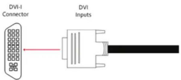
Figure B-18. DVI-I input.
An HDMI input is connected to the DVI-I connector using a DVI-HDMI Adapter.
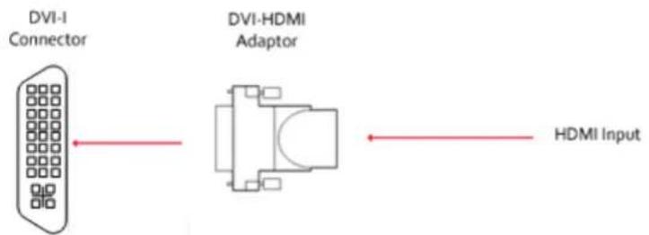
A Component input is connected to the DVI-I connector using the supplied DVI-Component Adapter.

Figure B-20. Component input.
An RGB (VGA) input is connected to the DVI-I connector using the supplied DVI-VGA Adapter:

flowchart
graph LR
    A["DVI-I Connector"] --> B["DVI-VGA Adaptor"]
    B --> C["RGB (VGA) Input"]
Figure B-21. RGB (VGA) input.
A standard definition signal can be connected to the RCA connector on the VCC-SDI-SD-HD-3.
RCA Connector (Female)

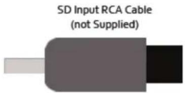
Figure B-22. Standard definition input.
SDI input is connected to the VCC-SDI-SD-HD-3 using the BNC connector (cable not supplied).

Figure B-23. VCC-SDI-SD-HD-3 bracket.
Cable Length
The VCC-SDI-SD-HD-3 supports cable lengths of up to 480 feet (150 meters). for 3G-SDI. This figure is based on using low-loss coax cable (Belden 1694A).
Using the Optional Audio Module (AM2)
Audio is connected to the AM2 using the Audio Break Out cable provided with the AM2.
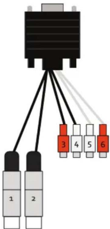
Figure B-24. Audio feed input.
Table B-X. Audio feed input signals.
| Connector Signal | |
| 1 Balanced (XLR) input left | |
| 2 Balanced (XLR) Input Right | |
| 3 Unbalanced | Input Left |
| 4 Unbalanced | Input Right |
| 5 Audio Out Left | |
| 6 Audio Out Right | |
B.3.6 Installing Multiple Cards
Multiple cards can be installed in a system, providing a large number of capture channels. Combinations of Radian Video Wall Processor capture cards in the same machine are supported by the Radian Video Wall Processor driver.
To control the order in which the driver uses the cards, we recommend when installing multiple cards that you configure the J6 links on the VCC-SDI-SD-HD-3. The example below shows the jumper link settings for up to 32 cards in a single system. When two cards share the same link settings, their order is determined by the PCIe bus.

Figure B-25. Card ordering.
DirectShow
If you change the link ordering after installation, you must run dplinks.exe. This program will update the existing input names used by the windows DirectShow interface.
To run the dplinks program, click on Start/Run and type dplinks, and then press Enter.
The program will run, but no notifications are displayed.
B.3.7 Firmware Upgrades
The VCC-SDI-SD-HD-3 cards allow firmware upgrade to be completed on site rather than returning the card to Black Box. Whenever a firmware upgrade is performed, the J8 Link MUST BE FITTED on the VCC-SDI-SD-HD-3. To perform the upgrade, follow the step-by-step instructions provided by the upgrade application.
If something goes wrong during the upgrade process (e.g., system power outage), you can revert to the factory settings by powering down the system, temporarily removing the J8 link, then powering up the system with the link removed. Once the system reboots, replace the J8 link link (while the system is powered up), and restart the firmware upgrade process.
NOTE: The latest driver installation program includes an automatic firmware update, if required. Before installing the application and driver, ensure that the J8 link is fitted.
B.3.8 Software Installation
The Video Capture Card software (driver and application) is installed by inserting the CD that was shipped with your card into a CD drive on your PC. The installation process should start automatically.
If the CD fails to autorun, browse the CD, locate, then double-click on install.exe file; e.g., d:/install.exe and click on Install Software... and follow the installation wizard instructions as prompted.
Application Overview
The application displays the connected source in a window; it has the following features:
- Scales the data to fit in the window.
- Ability to set up sources accurately (settings automatically saved).
- Save a single frame to a file in one of the following formats: BMP, JPEG, GIF, TIFF, PNG.
- Print a single frame.
- Maintain the aspect ratio of the displayed captured data.
- Cropping.
- Display text over the data (on-screen display).
- Command-line interface.
- Help file documenting all features.
NOTE: The supplied drivers and software require that you use Windows XP, Windows Vista, Windows Server 2003, Windows Server 2008, or Windows 7 (x86 and x64 operating systems) or Linux (audio not supported)
- Cd drive
Using the card with other Video Wall Controller products
The VCC-SDI-SD-HD-3 captures data and stores it in an on-board video buffer. This data is then copied using DMA to the host system for display, storage, or streaming.
When a Video Wall Controller graphics card is used, VCC-SDI-SD-HD-3 transfers the data directly to the graphics card, increasing performance. The VCC-SDI-SD-HD-3 sends the relevant portions of each captured image to each display channel and instructs each channel to use its graphics engine to render the data. This fully uses the hardware and dramatically increases performance.
When a Direct3D compatible graphics card is used, the data can be transferred directly to the graphics card in a similar manner as the Radian Video Wall Processor graphics card, with the same benefit of non-tearing captures.
When the data is displayed on a non Radian Video Wall Processor graphics card, the VCC-SDI-SD-HD-3 sends the data to system memory or directly to the graphics card, depending on the software used for display.
B.4 Video Capture Card (VCC-HD-4): (4) channel DVI/RGB/HD capture card
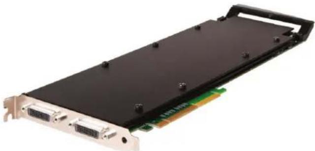
natural_image
Electronic hardware card with black top, gold connectors, and green circuit board (no visible text or symbols)Figure B-26. Video Capture Card (VCC-HD-4) illustrated.
B.4.1 Introduction
The VCC-HD-4 has four on-board video capture channels: two HDMI 1.4 channels offer 3840 x 2160 @ 30 frames per second (fps) and two HDMI 1.3 channels offer 1920 x 1080 @ 60 fps, all operating independently of each other. This enables four separate video sources to be captured and controlled simultaneously. The VCC-HD-4 card also has embedded audio support across all four channels.
Features
• LiveStream Technology: Low latency video and audio capture minimizes the delay prior to post processing.
- MultiStream: Open and independently control multiple instances of the same capture from a single input source.
- Powerful hardware scaler: Adjust the incoming video size to your requirements.
- Text and bitmap overlay: Overlay text and images onto the capture buffer.
• Automatic video signal detection: Accurate signal detection for all signal sources.
B.4.2 Hardware Overview
Quad Channel Video Capture
- Audio Capture
- Embedded audio support across all four channels.
• HDMI / DVI / RGB / YPbPr Video Capture
• Maximum resolution up to 4096 x 2048, at 165 MHz Pixel Clock (Digital modes) or 170 Msps in analog modes. - HDMI audio capture with streaming from each DVI Channel.
- 800 MB/s bandwidth per capture processor, 3.2 GB/s for the card.
Audio Features
HDMI Audio capture and streaming from each DVI Channel supports audio capture to the PCI Express bus at popular sample rates from 44.1 to 96 ksamples/s at 16 bits/sample. The card supports playback and mixing of HDMI embedded audio.
B.4.3 What's Included
Your packing box should contain the following items:
VCC-HD-4 - Quad HDMI video capture card
NOTE: All plug-in cards are static sensitive and are packed in anti-static material. Please keep the card in its packaging until you are ready to install.
We recommend that you do not discard the packing box until you are completely satisfied with the capture card and it is fully installed and working correctly. We also recommend that you note the serial number of the card in a prominent place before the card is plugged into the computer. This should hasten any query if you need to contact Black Box Technical Support. The serial number is displayed on the card itself and the box label.
B.4.4 Installing the Capture Card
You are likely to need a flat blade and /or a cross head screwdriver for the installation of the VCC-HD-4 card; it would be useful to have these to hand before you begin.
- Power down the PC (including peripherals), switch off the main power, and disconnect all the cables connected to the computer, noting the positions for accurate reconnection.
- Remove the PC cover.
- Locate a vacant PCI Express slot (x4 or higher) on the motherboard and remove the blanking plate (retain all screws).
NOTE: If you are in doubt, consult your motherboard documentation to correctly identify a PCI Express slot. If the card is forced into a 32 or 64 bit PCI or PCI-X slot, it will be irreparably damaged when the system is powered up and the warranty will be void.
-
Reconnect all cables to the PC, then connect input cables, distributing the video source signal to a connectors on the VCC-HD-4 capture card.
-
Power up the PC and begin installing the software.
The VCC-HD-4 card has two DSM59 connectors, the connectors support DVI or HDMI, using the supplied splitter cables where required.

natural_image
Close-up of a DVI-DNA connector with four connected VGA connectors (no text or symbols visible)Figure B-27. VCC-HD-4 with splitter cables.
Be careful when connecting the splitter cables to the VCC-HD-4 card. Do not force the cable into the connector. Forcing the cable into the connector could cause damage not covered by the warranty.
B.4.6 How to Connect Input Sources
A DVI input connects directly into the DVI-I connector that accepts DVI-D (digital) or DVI-A (analog) inputs.

Figure B-28. DVI input.
An HDMI input is connected to the DVI-I connector using the supplied DVI-HDMI Adapter.

A Component input is connected to the DVI-I connector using the supplied DVI-Component Adapter.

flowchart
graph LR
    A["DVI-I Connector"] --> B["DVI-Component Adapter"]
    B --> C["Component Input"]
    style A fill:#f9f,stroke:#333
    style B fill:#ccf,stroke:#333
    style C fill:#dfd,stroke:#333
Figure B-30. Component input.
An RGB (VGA) input is connected to the DVI-I connector using the supplied DVI-VGA Adapter:

flowchart
graph LR
    A["DVI-I Connector"] --> B["DVI-VGA Adaptor"]
    B --> C["RGB (VGA) Input"]
B-31. RGB (VGA) input.
B.4.6 Installing Multiple Cards
Multiple cards can be installed in a system, providing a large number of capture channels. Combinations of Radian Video Wall Processor capture cards in the same machine are supported by the Radian Video Wall Processor driver.
To control the order in which the driver uses the cards, we recommend when installing multiple cards that you configure the J5 links on the VCC-HD-4. The example below shows the jumper link settings for up to 32 cards in a single system. When two cards share the same link settings, their order is determined by the PCIe bus.

Figure B-32. Card ordering.
DirectShow
If you change the link ordering after installation you must run dplinks.exe. This program will update the existing input names used by the windows DirectShow interface.
To run the dplinks program, click on Start/Run and type dplinks, and then press Enter.
The program will run, but no notifications are displayed.
B.4.7 Firmware Upgrades
The VCC-HD-4 cards allow you to upgrade firmware on site rather than returning the card to Black Box. Whenever a firmware upgrade is performed, the SW2 on the DIP switch must be set ON. The DIP Switch can be located on the back of the VCC-HD-4 To perform the upgrade, follow the step-by-step instructions provided by the upgrade application. The VCC-HD-4 is shipped with the SW2 switch set at on, no action is necessary.
If something goes wrong during the upgrade process (e.g. System power outage), you can revert to the factory settings by powering down the system, temporarily setting SW2 to the OFF position, then powering up the system. Once the system reboots, set the SW2 back to the ON position (while the system is still powered up) and restart the firmware upgrade process.
NOTE: The latest driver installation program includes an automatic firmware update, if required. Before installing the application and driver, make sure that SW2 is set to on.
B.5 Video Capture Card (VCC-DP-2): (2) channel DisplayPort 4K capture card
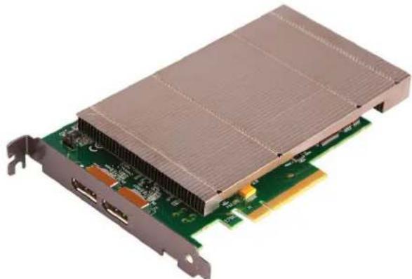
natural_image
Close-up of a green PCI expansion card with heat sink and ports (no text or symbols visible)Figure B-33. VCC-DP-2.
B.5.1 Introduction
The professional AV market has begun to adopt 4K UHD technologies, with integrators and system builders demanding higher performance and greater resolutions in the video that they are working with. The VCC-DP-2 offers video professionals the ability to simultaneously capture multiple 4K, Ultra High Definition, video feeds each at 60 frames per second. Developed as part of the Radian Video Wall Processor capture cards, the VCC-DP-2 offers unmatched capture performance and reliability.
- Two independent Display Port 1.2 Capture channels.
- Eight lane PCIe Gen.3 interface, Net 6.4 GB/s total capture bandwidth.
• Frame buffer memory of 768 MB. - Up to 8k x 8k capture resolution available at lower frame rates*.
* 8K x 8K at lower frame rates supported based on preliminary testing. Further testing to be scheduled when 8K sources are available.
Features
- LiveStream Technology: Low latency video and audio capture minimizes the delay prior to post processing.
- MultiStream: Open and independently control multiple instances of the same capture from a single input source.
- Powerful hardware scaler: Adjust the incoming video size to your requirements.
- Text and bitmap overlay: Overlay text and images onto the capture buffer.
• Automatic video signal detection: Accurate signal detection for all signal sources.
* 8K x 8K at lower frame rates supported based on preliminary testing. Further testing to be scheduled when 8k sources are available.
B.5.2 Hardware Overview
Dual Channel Video Capture:
• Channel 1: DisplayPort 1.2 (RBR/HBR/HBR2)
• Channel 2: DisplayPort 1.2 (RBR/HBR/HBR2)
Audio Capture:
• DisplayPort Embedded audio (16-24 bit, 32 kHz-48 kHz)
- Radian Video Wall Processor Performance Driver
- Multiple cards per system, 16 streams per card
• Frame sync and time stamping
• Automatic signal detection
- Direct Show interface
B.5.3 What's Included
Your packing box should contain the following items:
• VCC-DP-2 - Dual DisplayPort 1.2 capture card
NOTE: All plug-in cards are static sensitive and are packed in anti-static material. Please keep the card in its packaging until you are ready to install.
We recommend that you do not discard the packing box until you are completely satisfied with the VCC-DP-2 capture card and it is fully installed and working correctly. We also recommend that you note the serial number of the card in a prominent place before the card is plugged into the computer. This should hasten any query should you need to contact Black Box Technical Support. The serial number is displayed on the card itself and the box label.
B.5.4 Installing the Capture Card
You are likely to need a flat blade and /or a cross head screwdriver to install the VCC-DP-2 card; it would be useful to have these to hand before you begin.
- Power down the PC (including peripherals), switch off at the mains and disconnect all the cables connected to the computer, noting the positions for accurate re-connection.
- Remove the PC cover.
- Locate a vacant PCI Express slot (x4 or higher) on the motherboard and remove the blanking plate (retain all screws).
NOTE: If you are in doubt, consult your motherboard documentation to correctly identify a PCI Express slot. If the card is forced into a 32 or 64 bit PCI or PCI-X slot, it will be irreparably damaged when the system is powered up and the warranty will be void.
- Reconnect all cables to the PC then connect a DisplayPort cables, distributing the video source signal to DisplayPort connectors on the VCC-DP-2.
B.5.5 How to Connect Input Sources
The VCC-DP-2 card has two locking DisplayPort 1.2 connectors.

Figure B-34. Connectors.
When removing the DisplayPort cables from the VCC-DP-2, press release button on the connector to allow the cable to release freely.

natural_image
Diagram showing two connected USB cable connectors with red arrows indicating input/output connections (no text or symbols)Figure B-35. Removing cables.
Cable Settings
When using the VCC-DP-2, a cable settings function becomes available in the Input Settings of the software application. DisplayPort sources often train the cable link at the maximum available bit rate, even if it is not needed for the required display resolution. Some longer cables may be unable to train reliably at these higher bit rates. The Cable Settings drop-down menu allows the user to select a lower maximum bit rate to ensure a stable link.

Figure B-36. Cable Settings screen.
B.5.6 Installing Multiple Cards
You can install multiple cards in a system, providing a large number capture channels. Combinations of Radian Video Wall Processor capture cards in the same machine are supported by the Radian Video Wall Processor driver.
To control the order in which the driver uses the cards, we recommend when installing multiple cards that you configure the J5 links on the VCC-DP-2. The example below shows the jumper link settings for up to 32 cards in a single system. When two cards share the same link settings, their order is determined by the PCIe bus.

Figure B-37. Card ordering.
DirectShow
If you change the link ordering after installation, you must run dplinks.exe. This program will update the existing input names used by the windows DirectShow interface.
To run the dplinks program, click on Start/Run and type dplinks, and then press Enter.
The program will run, but no notifications are displayed.
8.5.7 Firmware Upgrades
The VCC-DP-2 cards allow firmware upgrade to be completed on site rather than returning the card to Black Box. Whenever a firmware upgrade is performed, the SW2 on the DIP switch must be set ON. The DIP Switch can be located on the back of the VCC-DP-2. To perform the upgrade, follow the step-by-step instructions provided by the upgrade application. The VCC-DP-2 is shipped with the SW2 switch set at on, so no action is necessary.
If something goes wrong during the upgrade process (e.g. System power outage), you can revert to the factory settings by powering down the system, temporarily setting SW2 to the OFF position, then powering up the system. Once the system reboots, set the SW2 back to the ON position (while the system is still powered up) and restart the firmware upgrade process.
NOTE: The latest driver installation program includes an automatic firmware update, if required. Before installing the application and driver, make sure that SW2 is set to on.
B.6 Video Capture Card (VCC-HD-4-H or VCC-HD-4-D)

natural_image
Close-up of a green computer card with multiple ports and connectors (no visible text or symbols)Figure B- 38. VCC-HD-4-H or VCC-SD-HD-4-D
B.6.1 Introduction
The VCC-HD-4 has four on board video capture channels; two channels of HDMI 1.4 offering 3840 x 2160 @ 30 frames per second (fps) and two HDMI 1.3 channels offering 1920 x 1080 @ 60 fps, all operating independently of each other. This enables four separate video sources to be captured and controlled simultaneously. The VCC-HD-4 card also has embedded audio support across all four channels.
Key Features
• LiveStream Technology: Low latency video and audio capture minimizes the delay prior to post processing.
- MultiStream: Open and independently control multiple instances of the same capture from a single input source.
- Powerful hardware scaler: Adjust the incoming video size to your requirements.
- Text and bitmap overlay: Overlay text and images onto the capture buffer.
• Automatic video signal detection: Accurate signal detection for all signal sources.
B.6.2 Hardware Overview
Table B-5. Quad Channel Video Capture
| Channel | TDMS Signaling | HDCP | Max. Resolution | Pixel Clock MHz |
| 1 | HDMI 1.4a | HDCP 1.4 | 4096 x 2160 | 297 |
| 2 | HDMI 1.4a | HDCP 1.4 | 2096 x 2096 | 165 |
| 3 | HDMI 1.4a | HDCP 1.4 | 4096 x 2160 | 297 |
| 4 | HDMI 1.4a | HDCP 1.4 | 2096 x 2096 | 165 |
Audio Capture
Embedded audio support across all four channels.
Radian Video Wall Processor Performance Driver
- Multiple cards per system, 16 streams per card.
• Frame sync and time stamping.
• Automatic signal detection. - Direct Show interface.
- RGBEasy API.
Models
VCC-HD-4-H - Capture card with 2 x HDMI splitter cables.
VCC-HD-4-D - Capture card with 2 x DVI splitter cables.
B.6.3 What's Included
Your packing box should contain the following items:
VCC-HD-4 - Quad HDMI video capture card and depending on which model ordered, either:
• (2) HDMI splitter cables, or
• (2) DVI splitter cables
NOTE: All plug-in cards are static sensitive and are packed in anti-static material. Keep the card in its packaging until you are ready to install.
We recommend that you do not discard the packing box until you are completely satisfied with the capture card and it is fully installed and working correctly. We also recommend that you make a note of the serial number of the card in a prominent place before the card is plugged into the computer. This should hasten any query should you need to contact our Technical Support Department. The serial number is displayed on the card itself and the box label.
B.6.4 Installing the Capture Card
You are likely to need a flat blade and /or a cross head screwdriver for the installation of the VCC-HD-4-H or VCC-HD-4D card; it would be useful to have these to hand before you begin.
-
Power down the PC (including peripherals), switch off the main power, and disconnect all the cables connected to the computer, noting the positions for accurate reconnection.
-
Remove the PC cover.
-
Locate a vacant PCI Express slot (x4 or higher) on the motherboard and remove the blanking plate (retain all screws).
NOTE: If you are in doubt, consult your motherboard documentation to correctly identify a PCI Express slot. If the card is forced into a 32 or 64 bit PCI or PCI-X slot, it will be irreparably damaged when the system is powered up and the warranty will be void.
-
Reconnect all cables to the PC, then connect input cables, distributing the video source signal to a connectors on the VCC-HD-4 capture card
-
Power up the PC and begin installing the software.
B.6.5 How to Connect Input Sources
The VCC-HD-4 card has two DSM59 connectors. The connectors support DVI or HDMI using the supplied splitter cables where required.

Figure B-39. Connecting input sources.
Be careful when connecting the splitter cables to the VCC-HD-4 card. Do not force the cable into the connector. Forcing the cable into the connector could cause damage not covered by the warranty.
B.6.6 Installing Multiple Cards
Multiple cards can be installed in a system providing a large number capture channels. Combinations of Radian Video Wall Processor capture cards in the same machine are supported by the Radian Video Wall Processor driver.
To control the order in which the driver uses the cards, we recommend when installing multiple cards that you configure the J5 links on the VCC-HD-4-H or VCC-HD-4-D. The example below shows the jumper link settings for up to 32 cards in a single system. When two cards share the same link settings, their order is determined by the PCIe bus.
Installing Multiple Cards

Figure B-40. Card ordering.
DirectShow
If you change the link ordering after installation, you must run dplinks.exe. This program will update the existing input names used by the windows DirectShow interface.
To run the dplinks program, click on Start/Run and type dplinks, and then press Enter.
The program will run, but no notifications are displayed.
B.6.7 Firmware Upgrades
The VCC-HD-4-H and VCC-HD-4-D cards allow firmware upgrade to be completed on site rather than returning the card to Black Box. Whenever a firmware upgrade is performed, the SW2 on the DIP switch must be set ON. The DIP Switch can be located on the back of the VCC-HD-4-H or VCC-HD-4-D. To perform the upgrade, follow the step-by-step instructions provided by the upgrade application. The VCC-HD-4-H or VCC-HD-4-D is shipped with the SW2 switch set at on, so no action is necessary.
If something goes wrong during the upgrade process (e.g. System power outage), you can revert to the factory settings by powering down the system, temporarily setting SW2 to the OFF position, then powering up the system. Once the system reboots, set the SW2 back to the ON position (while the system is still powered up) and restart the firmware upgrade process.
NOTE: The latest driver installation program includes an automatic firmware update, if required. Before installing the application and driver, ensure that SW2 is set to on.
B.7 Video Capture Card (VCC-SDI-4): (4) channel 3G-SDI capture card

natural_image
Close-up of a green PCI expansion card with multiple connectors and cooling fins (no text or symbols visible)Figure B-41. VCC-SDI-4 card.
B.7.1 Introduction
Developed for capturing multiple High Definition SDI video signals, the VCC-SDI-4 is the perfect solution to AV professionals looking to capture from multiple sources. Ideal for use in broadcast markets or with any SDI capable applications the VCC-SDI-4 provides four 3G-SDI inputs, each capable of capturing 1920 x 1080p @ 60 frames per second. Each capture channel is hardware time-stamped, allowing for larger surfaces to be captured and stitched together. Developed as part of the Radian Video Wall Processor selection of capture cards, the VCC-SDI-4 offers unmatched capture performance and reliability.
Key Features
• LiveStream Technology: Low latency video and audio capture minimizes the delay prior to post processing.
- MultiStream: Open and independently control multiple instances of the same capture from a single input source.
- Powerful hardware scaler: Adjust the incoming video size to your requirements.
- Text and bitmap overlay: Overlay text and images onto the capture buffer.
• Automatic video signal detection: Accurate signal detection for all signal sources
B.7.2 Hardware Overview
• Four Channel 3G-SDI Video Capture Card.
- Four independent 3G SDI capture channels.
• Four channels of 1920 x 1080p 60fps capture.
• Eight lane PCIe Gen.3 interface.
• Frame buffer memory—768 MB.
- Single PCIe endpoint, allowing for more cards & captures to be placed within a single system.
• Video Capture Card Driver.
- Multiple cards per system, 16 streams per card.
• Frame sync and time stamping.
• Automatic signal detection.
- Direct Show interface.
- RGBEasy API.
B.7.3 What's Included
Your packing box should contain the following items:
• VCC-SDI-4 - Four channel 3G-SDI video capture card
NOTE: All plug-in cards are static sensitive and are packed in anti-static material. Keep the card in its packaging until you are ready to install.
We recommend that you do not discard the packing box until you are completely satisfied with the VCC-SDI-4 capture card and it is fully installed and working correctly. We also recommend that you note the serial number of the card in a prominent place before the card is plugged into the computer. This should hasten any query if you need to contact Black Box Technical Support. The serial number is displayed on the card itself and the box label.
B.7.4 Installing the Capture Card
You are likely to need a flat blade and /or a cross head screwdriver for the installation of the VCC-SDI-4 card; it would be useful to have these to hand before you begin.
- Power down the PC (including peripherals), switch off the power and disconnect all the cables connected to the computer, noting the positions for accurate re-connection.
- Remove the PC cover.
- Locate a vacant PCI Express slot (x4 or higher) on the motherboard and remove the blanking plate (retain all screws).
NOTE: If you are in doubt, consult your motherboard documentation to correctly identify a PCI Express slot. If the card is forced into a 32 or 64 bit PCI or PCI-X slot, it will be irreparably damaged when the system is powered up and the warranty will be void.
-
Reconnect all cables to the PC.
-
Power up the PC and begin installing the software.
B.7.5 How to Connect Input Sources
The VCC-SDI-4 card has four BNC type connectors for four separate, simultaneous inputs. The connectors have green LEDs. Connect the cables to distribute the video source signal to BNC input connectors on the VCC-SDI-4 capture card.
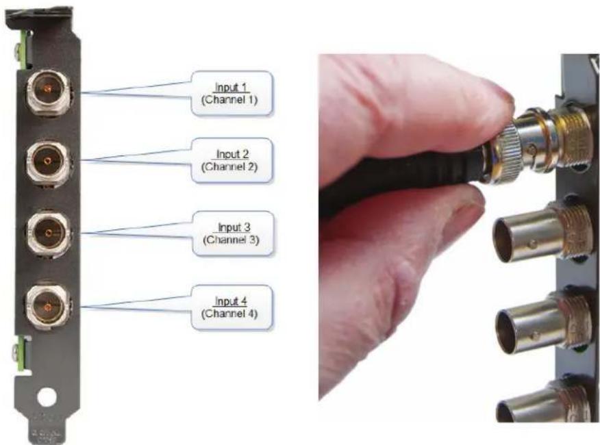
Figure B-42. Connecting input sources.
When connecting BNC cables, make sure connectors are fully twisted and locked in place. Failure to lock the connector can cause the BNC cable to separate from the card and the connection to be lost.
Cable Lengths
The VCC-SDI-4 supports cable lengths of up to 480 feet (150 meters) for 3G-SDI. This figure is based on using low-loss coax cables (Belden 1694A). Avoid tight loops or kinks in the cables.
B.7.6 Installing Multiple Cards

Figure B-43. Card ordering.
Multiple cards can be installed in a system, providing a large number capture channels. Combinations of Radian Video Wall Processor capture cards in the same machine are supported by the Radian Video Wall Processor driver.
To control the order in which the driver uses the cards, we recommend when installing multiple cards that you configure the J5 links on the VCC-SDI-4. The example below shows the jumper link settings for up to 32 cards in a single system. When two cards share the same link settings, their order is determined by the PCIe bus.
DirectShow
If you change the link ordering after installation, you must run dplinks.exe. This program will update the existing input names used by the windows DirectShow interface.
To run the dplinks program, click on Start/Run and type dplinks, and then press Enter.
The program will run, but no notifications are displayed.
B.7.6 Firmware Upgrades
The VCC-SDI-4 cards allow firmware upgrades to be completed on site rather than returning the card to Black Box. Whenever a firmware upgrade is performed, the SW2 on the DIP switch must be set ON. The DIP Switch can be located on the back of the VCC-SDI-4. To perform the upgrade, follow the step-by-step instructions provided by the upgrade application. The VCC-SDI-4 is shipped with the SW2 switch set at on, therefore no action should ne necessary.
If something goes wrong during the upgrade process (e.g., system power outage) you can revert to the factory settings by powering down the system, temporarily setting SW2 to the OFF position then powering up the system. Once the system reboots, set the SW2 back to the ON position (while the system is still powered up) and restart the firmware upgrade process.
NOTE: The latest driver installation program includes an automatic firmware update, if required. Before installing the application and driver, make sure that SW2 is set to on.
B.8 Video Capture Card (VCC-STREAM), Dedicated Decoding Card

natural_image
Close-up of a network card interface with Ethernet ports and a green circuit board (no visible text or labels)Figure B-44. VCC-STREAM card.
B.8.1 Introduction
Professional AV solutions require video to be received from many different sources and locations. The ability to receive and display video directly from online resources such as CCTV networks and remote desktop applications and combining them with local inputs has become an everyday part of a fully functional video wall display. The VCC-STREAM PCIe plug in card is a powerful addition to systems that require a hardware-based decoding solution.
The VCC-STREAM includes a dedicated processor capable of decoding several IP streams simultaneously via the on-board Ethernet ports. Fully PCIe compatible, multiple VCC-STREAM cards can be used in a single system to provide project scalability giving users more processing and more simultaneous decodes.
NOTE: All plug-in cards are static-sensitive and are packed in anti-static material. Keep the card in its packaging until you are ready to install.
We recommend that you do not discard the packing box until you are completely satisfied with the VCC-STREAM capture card and it is fully installed and working correctly. We also recommend that you note the serial number of the card in a prominent place before the card is plugged into the computer. This should hasten any query if you need to contact Black Box Technical Support. The serial number is displayed on the card itself and the box label.
B.8.2 Hardware Overview
The VCC-STREAM is a half-length PCI-Express plug-in card with two Gigabit Ethernet input nodes supporting real time decode of multiple IP streams. Using the VCC-STREAM decoding technology provides seamless integration of IP video to a Video Wall Controller.
Each VCC-STREAM card can capture a bandwidth equivalent to twelve 1920 x 1080 @ 30Hz streams on to any wall controller that uses Radian Video Wall Processor graphics cards. The number of streams the VCC-STREAM provides depends on a number of factors, such as the decoder profile used.
Each card uses a single PCIe slot, is passively cooled, and can easily be added to a system already using Video Wall Controller technology without changing existing configuration or front-end software. This transparent software model enables the number of supported IP streams to be scaled up quickly according to the user requirements. VCC-STREAM also automatically balances the total decoding workload across all VCC-STREAM cards in the system, allowing thermal power consumption to be distributed more efficiently.
Stream was designed to work alongside the Radian Video Wall Controller range of capture cards, supporting a mixture of local and remote capture feeds on the same display. IP Streams are displayed on the video wall in the same way as captured video sources. Stream functionality is compatible with many existing Video Wall Controller window features.
B.8.3 Installing VCC-STREAM Cards
You are likely to need a flat blade and/or a cross head screwdriver for the installation of the VCG-STREAM card; it would be useful to have these to hand before you begin.
- Power down the PC (including peripherals), switch off at the mains and disconnect all the cables connected to the computer, noting the positions for accurate re-connection.
- Remove the PC cover.
- Locate a vacant PCI Express slot (x4 or higher) on the motherboard and remove the blanking plate (retain all screws).
NOTE: If you are in doubt, consult your motherboard documentation to correctly identify a PCI Express slot. If the card is forced into a 32 or 64 bit PCI or PCI-X slot, it will be irreparably damaged when the system is powered up and the warranty will be void.
- Reconnect all cables to the PC, then connect network cables (not supplied) to the Ethernet port on the VCG-STREAM capture card.
- Power up the PC and commence the software installation.
- Multiple VCC-STREAM cards can be installed into a system to provide more processing and more simultaneous decodes.
NOTE: The VCC-STREAM card is only compatible with systems containing Vided Graphics Cards (VGC-DP-4, VGC-HD-4-D, VGC-HD-4-H) graphics cards.
The VCC-STREAM card has two Ethernet ports and one currently dormant output DisplayPort connector (reserved for future use).

natural_image
Close-up of a metallic electronic device with two ports and connectors (no visible text or symbols)Figure B-45. Connecting input sources.
Connect a network cable into one or both of the Ethernet ports. Be careful when connecting a network cable. Make sure the cable connector is pushed firmly into the Ethernet port until you hear a definite click. Failure to connect the network cable properly could cause the network connection to be lost.
Link LEDs
On the rear of the VCC-STREAM are a series of LEDs labelled PEX_LANE_GOOD.
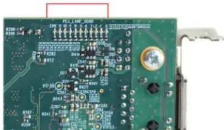
natural_image
Close-up of a green printed circuit board with visible traces, pads, and connectors (no readable text or symbols)Figure B-46. LEDs on VCC-STREAM card.
The green LEDs are labelled 0-5 and 8-11 these map to LEDs D4 to D13.
Table B-6. LEDs.
| LED Link Lane LED Status Normal Operation | |||||
| 0 | PCI Host Link lane 0 | On=Gen 2 | Flashing=Gen 1 | Off=Link not trained | On - Gen 2 |
| 1 | PCI Host Link lane 1 | On=Gen 2 | Flashing=Gen 1 | Off=Link not trained | On - Gen 2 |
| 2 | PCI Host Link lane 2 | On=Gen 2 | Flashing=Gen 1 | Off=Link not trained | On - Gen 2 |
| 3 | PCI Host Link lane 3 | On=Gen 2 | Flashing=Gen 1 | Off=Link not trained | On - Gen 2 |
| 4 | LAN 1 Link lane 0 | — | — | — | Flashing - Gen 1 |
| 5 | LAN 2 Link lane 0 | — | — | — | Flashing - Gen 1 |
| 8 | ATOM Link lane 0 | — | — | — | On - Gen 2 |
| 9 | ATOM Link lane 1 | — | — | — | On - Gen 2 |
| 10 | ATOM Link lane 2 | — | — | — | On - Gen 2 |
| 11 | ATOM Link lane 3 | — | — | — | On - Gen 2 |
B.8.4 IP Addressing
Out of the box, the VCC-STREAM card is configured to accept Dynamic IP addressing. Depending on the topology of your network, you may need to change this to a Static IP address.
To reconfigure the IP addressing, open the Device manager by selecting System and Security in the system Control Panel. From the System menu, select Device manager.
In the Device Manager, sound, video, and game controllers and the VCC-STREAM card(s) is(are) displayed.
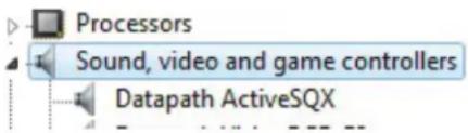
Figure B-47. Sound, video and game controllers option.
Right-click on the VCC-STREAM, then select properties from the displayed menu. Click on the Configuration tab and the Configuration dialog is displayed.
To configure a static IP address, select "Use the following IP address." The IP address box will be populated automatically with an IP address allocated by the network. You can either keep this IP address as your static address or create one of your own.

Figure B-48. IP address screen.
LAN1 and LAN2 operate independently. They both require configuring as a Static IP address. Repeat this process for LAN2 by clicking on the LAN2 tab.
B.8.5 Software Overview
The VCC-STREAM requires little configuration to be up and running; the your software should detect the card and allow you to add IP camera windows to your display wall. The card opens a gateway to the network enabling the user to add, configure and modify IP cameras using the VWS-2001, VWS-2002, or VWS-2003 software.
The application displays the connected source in a window on your desktop; it has the following features:
- Scales the data to fit in the window.
- Ability to set up sources accurately (settings automatically saved).
- Command line interface.
Alternatively, use the SQXEasy SDK.
NOTE: The supplied drivers and software require that you use:
• Windows® 7 64 bit / Server 2012
- CD drive
Software Installation
The VWS-2001, VWS-2002, or VWS-2003 software (driver and application) is installed by inserting the CD that was shipped with your card into a CD drive on your PC. The installation process should start automatically.
If the CD fails to autorun, browse the CD, locate, then double-click on install.exe file; e.g., d:/install.exe and click on Install Software... and follow the installation wizard instructions as prompted.
Firmware Upgrades
The VCC-STREAM cards allow firmware upgrades to be completed on-site rather than returning the card to Black Box. Whenever a firmware upgrade is performed, the JP8 Link MUST BE FITTED on the VCC-STREAM card.
To perform the upgrade, follow the step-by-step instructions provided by the upgrade application.
If something goes wrong during the upgrade process (e.g. System power outage), you can revert to the factory settings by powering down the system, temporarily removing the JP8 link, then powering up the system with the link removed.
Once the system has rebooted, replace the JP8 link (while the system is powered up) and restart the firmware upgrade process.
NOTE: The latest driver installation program includes an automatic firmware update, if required. Before installing the application and driver, ensure that J8 link is fitted.
B.8.6 Troubleshooting
Using the card with other products:
Black Box Stream technology is compatible with industry standards for video compression and streaming. The VCC-STREAM card can be used in Radian Video Wall Processor systems alongside the Radian Video Wall Processor range of capture cards. Combined with the card, it provides a full decode and encode capability in a single system.
The VCC-STREAM is totally integrated within the VWS-2002 software enabling IP streams to be configured and displayed anywhere on the display wall with display window functionality such as Carousel that allows you to create a display list of IP streams that can cycle through and display for a specific duration.
Appendix C. Installing the Expansion Chassis
Available models include:
- Expansion Chassis (VWX-2090), 600 W RPSU, works with VWP-2090.
- Expansion Chassis (VWX-2110), 800 W RPSU, works with VWP-2110.
See Chapter 3 for more information.
Appendix D. Radian Video Wall Processor Software Capabilities
- Timestamp support for streaming synchronization.
- Synchronize multiple inputs across multiple cards.
- Synchronize systems using network clock synchronization.
- Use for edge blending and other applications.
- Flexible and configurable EDID Management allows programming of custom EDID parameters for capture cards.
- Low Input to Output Capture Latency.
- DMA to third party graphics vendors back and front buffers via Direct3D.
- Compatibility with AMD DirectGMA.
- Compatibility with Nvidia GPUDirect.
- User Mode filter for source selection.
- Enables cropping support in DirectShow on all inputs.
- Supports start-and-stop trigger interface on all Radian Video Wall Processor Card inputs.
- Radian Video Wall Processor Driver.
- Multiple cards per system, 16 streams per input.
• Frame sync and time stamping. - DirectShow interface.
- RGBEasy API for advanced audio and video control.
- Fully integrated for use with Radian Video Wall Processor software for video wall applications.
- Multistream: Enables multiple independently formatted video streams to be setup in parallel. Each stream can be formatted completely independently, and you can select resolution, color space, and cropping region individually for each stream. This maximizes bandwidth use of the capture card PCIe interface, and also simplifies development tasks for application developers who do not need to implement video stream reformatting separately.
The application displays the connected source in a window; it has the following features: - Scales the data to fit in the window.
- Ability to set up sources accurately (settings automatically saved).
- Save a single frame to a file in one of the following formats: BMP, JPEG, GIF, TIFF, PNG.
- Print a single frame.
- Maintain the aspect ratio of the displayed captured data.
- Cropping.
- Display text over the data (on-screen display).
- Command-line interface.
- HDCP supported.
- Help file documenting all features.
Radian Video Wall Processor Application Overview
NOTE: The supplied drivers and software require that you use:
- Windows XP, Windows Vista, Windows Server 2003, Windows Server 2008, Windows 7 (x86 and x64 Operating Systems), Windows 8, or Linux (audio not supported)
- CD drive
Using the card with other Radian Video Wall Processor products
The Video Capture Cards captures data and stores it in an on-board video buffer. This data is then copied using DMA to the host system for display, storage or streaming.
When a Radian Video Wall Processor graphics card is used, the Video Capture Card transfers the data directly to the graphics card, increasing performance. The Video Capture Card sends the relevant portions of each captured image to each display channel and instructs each channel to use its graphics engine to render the data. This fully uses the hardware and dramatically increases performance.
When a Direct3D compatible graphics card is used the data can be transferred direct to the graphics card in a similar manner to the graphics card with the same benefit of non-tearing captures.
When the data is displayed on a non Radian Video Wall Processor graphics card, the Video Capture Card sends the data to system memory or direct to the graphics card, depending on the software used for display.
Black Box Tech Support: FREE! Live. 24/7.
Tech support the way it should be.

natural_image
Close-up portrait of a smiling man holding a small object, against a blue background (no text or symbols visible)Great tech support is just 60 seconds away at 877-877-2269 or blackbox.com.

BLACK BOX®
About Black Box
Black Box provides an extensive range of networking and infrastructure products. You'll find everything from cabinets and racks and power and surge protection products to media converters and Ethernet switches all supported by free, live 24/7 Tech support available in 60 seconds or less.
© Copyright 2016. Black Box Corporation. All rights reserved. Black Box ^® and the Double Diamond logo are registered trademarks of BB Technologies, Inc. Any third-party trademarks appearing in this manual are acknowledged to be the property of their respective owners.
VWP-2040_user_rev1
- Radian Video Wall Processor
- User Manual
- Trademarks Used in this Manual
- Federal Communications Commission and Industry Canada Radio Frequency Interference Statements
- Power Supply
- Cables
- Ventilation
- Working Environment
- Gas/Flammable Liquids
- Smoke/Unusual Smells
- Maintenance
- Disposal
- Rackmount Safety Instructions
- Temperature
- Mechanical Loading
- Circuit Overloading
- Reliable Earthing
- Replaceable Batteries
- Table of Contents
- Specifications.... 10
- Overview 24
- Onboard Graphics Adapter 35
- Hardware Installation....39
- Software Overview....47
- Specifications
- Radian Video Wall Processor Chassis, VWP-2040, VWP-2090, VWP-2110
- Video Capture Card (VCC-SDI-SD-HD-3): (1) HD channels + (1) HD-SDI channel + (1) SD channel, full height
- Overview
- Introduction
- Features
- Available Components
- What's Included
- VWP-2040
- VWP-2090
- VWP-2110
- Radian Video Wall Processor Cards
- Hardware Description
- VWP-2040
- VWP-2090
- VWP-2110
- Video Graphics and Video Capture Cards
- Cables and Adapters
- Onboard Graphics Adapter
- Video Graphics Card BIOS (VWP-2090 or VWP-2110)
- Using the Onboard Graphics Adapter for the VWP-2040
- Onboard Graphics Adapter used as Control Screen (VWP-2040)
- Onboard Graphics Adapter Disabled (VWP-2040)
- Onboard Graphics Adapter for the VWP-2090 or VWP-2110
- Onboard Graphics Adaptor used as Control Screen (VWP-2090 or VWP-2110)
- Onboard Graphics Adaptor Disabled (VWP-2090 or VWP-2110)
- Hardware Installation
- V WP-2040
- VWP-2090 Backplane Layout
- VWP-2090 Backplane Layout
- Connecting the VWX-2090 Expansion Chassis to the VWP-2090 Radian Video Wall Processor Chassis
- VWP-2110 Backplane Layout
- VWP-2110 Backplane Layout
- Connecting the VWX-2110 Expansion Chassis to the VWP-2110 Radian Video Wall Processor Chassis
- Software Overview
- V W S -2001
- Video Wall Controller and IP Camera Window Control
- Application Control
- Intuitive User Interface
- On Screen Display (OSD)
- Remote Control
- Layout and Offline Support
- Command-Line Interface
- Audio Support
- Carousel
- Video Wall Screen Order
- RS-232 and TELNET Support for Crestron/AMX Controllers
- Multi-Language Support
- Video Capture Card Software
- Video Streaming
- Video Capture Cards Software Capabilities
- Unified Video Capture Cards Driver
- Multistream
- Filter Maintenance (VWP-2090 or VWP-2110)
- Remove the Filter
- Appendix A. Installing the Video Graphics Card (VGC-DP-4, VGC-HD-4-D, or VGC-HD-4-H)
- A.1 Introduction
- A.2 Features
- System Requirements
- Unpacking
- A.3 Installing the Video Graphics Card
- A.3.1 Installing the Display Drivers
- A.3.2 Installing Additional Video Graphics Cards
- Power
- A.4 Video Graphics Card Video BIOS
- A.5 Card Ordering
- DisplayPort Outputs
- A.6 Multi-Screen Configuration
- No. Screens
- Screen Arrangement:
- Force DVI Output:
- Prune Modes:
- A.7 Defining Custom Modes
- A.8 Screen Order
- Connecting Screens
- Changing the Order of the Screens
- Appendix B. Installing the Video Capture Cards
- B.1 Video Capture Card (VCC-SD-HD-A-2): (1) HD channel
- B.1.1 Introduction
- B.1.2 Hardware Overview
- Video Capture Card Driver
- B.1.3 What's Included
- B.1.4 Installing the Video Capture Card (VCC-SD-HD-A-2)
- B.1.5 How to Connect Input Sources
- B.1.6 Installing Multiple Cards
- DirectShow
- B.1.7 Firmware Upgrades
- B.1.8 Software Installation
- B.2 Video Capture Card (VCC-SD-HD-3)
- B.2.1 Introduction
- B.2.2 Hardware Overview
- B.2.3 What's Included
- B.2.4 Installing the Capture Card
- B.2.5 How to Connect Input Sources
- B.2.6 Installing Multiple Cards
- B.2.7 Firmware Upgrades
- B.2.8 Software Installation
- B.3.1 Introduction
- Features
- B.3.2 Hardware Overview
- B.3.3 What's Included
- B.3.4 Installing the Capture Card
- B.3.5 How to Connect Input Sources
- Cable Length
- B.3.6 Installing Multiple Cards
- B.3.7 Firmware Upgrades
- B.3.8 Software Installation
- Using the card with other Video Wall Controller products
- B.4 Video Capture Card (VCC-HD-4): (4) channel DVI/RGB/HD capture card
- B.4.1 Introduction
- B.4.2 Hardware Overview
- Quad Channel Video Capture
- Audio Features
- B.4.3 What's Included
- B.4.4 Installing the Capture Card
- B.4.6 How to Connect Input Sources
- B.4.6 Installing Multiple Cards
- B.4.7 Firmware Upgrades
- B.5 Video Capture Card (VCC-DP-2): (2) channel DisplayPort 4K capture card
- B.5.1 Introduction
- B.5.2 Hardware Overview
- B.5.3 What's Included
- B.5.4 Installing the Capture Card
- B.5.5 How to Connect Input Sources
- Cable Settings
- B.5.6 Installing Multiple Cards
- Firmware Upgrades
- B.6 Video Capture Card (VCC-HD-4-H or VCC-HD-4-D)
- B.6.1 Introduction
- Key Features
- B.6.2 Hardware Overview
- Audio Capture
- Radian Video Wall Processor Performance Driver
- Models
- B.6.3 What's Included
- B.6.4 Installing the Capture Card
- B.6.5 How to Connect Input Sources
- B.6.6 Installing Multiple Cards
- B.6.7 Firmware Upgrades
- B.7 Video Capture Card (VCC-SDI-4): (4) channel 3G-SDI capture card
- B.7.1 Introduction
- B.7.2 Hardware Overview
- B.7.3 What's Included
- B.7.4 Installing the Capture Card
- B.7.5 How to Connect Input Sources
- Cable Lengths
- B.7.6 Installing Multiple Cards
- B.7.6 Firmware Upgrades
- B.8 Video Capture Card (VCC-STREAM), Dedicated Decoding Card
- B.8.1 Introduction
- B.8.2 Hardware Overview
- B.8.3 Installing VCC-STREAM Cards
- Link LEDs
- B.8.4 IP Addressing
- B.8.5 Software Overview
- Software Installation
- Firmware Upgrades
- B.8.6 Troubleshooting
- Appendix C. Installing the Expansion Chassis
- Appendix D. Radian Video Wall Processor Software Capabilities
- Radian Video Wall Processor Application Overview
- Black Box Tech Support: FREE! Live. 24/7.
- BLACK BOX®
- About Black Box
Brand : Black Box
Model : VWP-2110
Category : Video Conferencing System