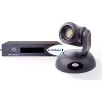
RoboSHOT 30 OneLINK HDBT - Video Conferencing System Vaddio - Free user manual and instructions
Find the device manual for free RoboSHOT 30 OneLINK HDBT Vaddio in PDF.


| Product Type | High-Performance PTZ Camera for Video Conferencing |
| Model Number | RoboSHOT 30 HDBT (999-9963-000, 999-9963-001, 999-9963-009) |
| Image Sensor | 1/2.8-Type Exmor R back-lit CMOS, 2.38 MP total |
| Optical Zoom | 30X |
| Horizontal Field of View | 65° (wide) to 2.3° (tele) |
| Video Output Resolution | 1080p/60, 1080i/60, 720p/60, and lower (selectable) |
| IP Streaming | H.264 via RTSP, up to 1080p/30 |
| Pan Range | ±160° |
| Tilt Range | +90° to -30° |
| Pan/Tilt Speed | 0.35°/sec to 120°/sec |
| Control Interfaces | IR Remote, Web UI, Telnet, RS-232 (VISCA-like) |
| Power Supply | 12 VDC, 3.0 A (included) or PoE+ (IEEE 802.3at) |
| Dimensions (H x W x D) | 6.9 x 7.1 x 6.8 in (176 x 179 x 172 mm) |
| Weight | 4.85 lb (2.2 kg) |
| Mounting | Thin Profile Wall Mount included; ceiling mount compatible with inverted settings |
| Special Features | Tri-Synchronous Motion, Auto Focus, Backlight Compensation, Wide Dynamic Range |
| Operating Temperature | 32°F to 104°F (0°C to 40°C) |
| Storage Humidity | 20% to 80% RH (non-condensing) |
| Included Accessories | IR Remote Commander, power supply, wall mount, Quick-Start Guide |
| Warranty | 2 years limited (parts and labor) |
Frequently Asked Questions - RoboSHOT 30 OneLINK HDBT Vaddio
User questions about RoboSHOT 30 OneLINK HDBT Vaddio
0 question about this device. Answer the ones you know or ask your own.
Ask a new question about this device
Download the instructions for your Video Conferencing System in PDF format for free! Find your manual RoboSHOT 30 OneLINK HDBT - Vaddio and take your electronic device back in hand. On this page are published all the documents necessary for the use of your device. RoboSHOT 30 OneLINK HDBT by Vaddio.
USER MANUAL RoboSHOT 30 OneLINK HDBT Vaddio
natural_image
Two white and black VR headset models with camera lenses, displayed against a blue background (no text or symbols visible)Integrator's Complete Guide to
RoboSHOT 12 HDBT and
RoboSHOT 30 HDBT
High-Performance PTZ Cameras
Document 411-0003-30 Rev. C
February 2017
Contents
Overview 1.
What's in this Guide.1....
Camera Features.1....
Unpacking the Camera 2....
A Quick Look at the Camera 5.
Front of the Camera 5....
Back of the Camera.6....
Switch Settings.6
Video Resolution 6.
Camera Settings.7....
Installation 8.
Before You Install the Camera.... 8
Don't Void Your Warranty! 8
Cabling Notes 9
Installing the Wall Mount.... 10
About Ceiling-Mounted Cameras.... 10
Basic Connection Diagram.... 11
Options for Power and Other Connections.... 11
Installing the Camera.... 12
Powering Up the Camera.... 13
Vaddio IR Remote Commander.... 14
IR Remote Cheat Sheet 14
IR Remote Details 15
Storing a Preset Using the IR Remote Commander.... 15
Clearing a Preset Using the IR Remote Commander.... 15
Getting the Camera's IP Address.... 15
Web Interface 16
Compatible Web Browsers 16
User Access 17
Administrative Access.... 18
Web Interface Cheat Sheet.... 19
Web Tasks for All Users: Controlling the Camera 20
Switching the Camera Off or On 21
Moving the Camera 21
Zooming In or Out 21
Changing the Focus 22
Moving the Camera to a Preset Position 23
Selecting the Appropriate Color Settings 24
Storing a Camera Preset 25
Changing the Speed of Camera Movements 26
Setting Pan Direction 27
Setting Tilt Direction 27
Web Tasks for Administrators: Setting a Custom Home Position 28....
Web Tasks for Administrators: Managing Access and Passwords 29....
Web Tasks for Administrators: Adding Room Information to the Web Interface.29...
Web Tasks for Administrators: Configuring Network Settings 30
Specifying Time Zone and NTP Server 31.
Web Tasks for Administrators: Configuring Streaming Settings.32....
Enabling or Disabling Streaming 32
Editing IP Streaming Settings 33
Advanced IP Streaming Settings 34
Web Tasks for Administrators: Setting Camera Behaviors and Adjustments.... 35
Setting Up Custom Color and Lighting Settings 36
Renaming a Custom CCU Scene 36
Setting Pan, Tilt, and Zoom Speeds 36
Web Tasks for Administrators: Rebooting, Updating, and Resetting 37
Rebooting the Camera 37
Saving (Exporting) or Restoring (Importing) a Configuration 37
Starting a Firmware Update 38
Restoring Factory Settings 38
Reading the Camera's Back Panel Switches 39
Setting the LED Color Scheme 39
Web Tasks for Administrators: Contacting Vaddio Technical Support 40
Web Tasks for Administrators: Viewing Diagnostic Logs 41
Telnet Serial Command API 42
camera home 43
camera pan 43
camera tilt 44
camera zoom 44
camera focus 45
camera preset 46
camera ccu get 47
camera ccu set 48
camera ccu scene 49
camera standby 49
streaming settings get 50
network settings get 50
network ping....51
system reboot 51
system factory-reset 52
sleep 52
history 53
version .53
help 54
exit 54
RS-232 Serial Communication 55
RS-232 Command List 56
Command Setting Values 63....
Exposure Compensation 63
Shutter Speed Values 64
Iris Position Values 65
Iris Gain Values 66
Iris Gain Limit Values 66
RS-232 Inquiry Command List 67
Specifications 71
Troubleshooting and Care 72
Operation, Storage, and Care 73
Compliance Statements and Declarations of Conformity 74
FCC Part 15 Compliance 74
ICES-003 Compliance 74
European Compliance 75
Warranty Information 76
Index 77
Overview
This guide covers the RoboSHOT™ 12 and 30 HDBT PTZ cameras;
■ RoboSHOT 12 HDBT (silver), North America – 999-9960-000
■ RoboSHOT 12 HDBT (silver), Europe and UK - 999-9960-001
■ RoboSHOT 12 HDBT (silver), Australia and New Zealand – 9999960-009
■ RoboSHOT 30 HDBT (black), North America – 999-9963-000
■ RoboSHOT 30 HDBT (black), Europe and UK – 999-9963-001
■ RoboSHOT 30 HDBT (black), Australia and New Zealand – 999-9963-009
■ RoboSHOT 30 HDBT (white), North America – 999-9963-000W
■ RoboSHOT 30 HDBT (white), Europe and UK - 999-9963-001W
■ RoboSHOT 30 HDBT (white), Australia and New Zealand – 999-9963-009W

natural_image
Three camera modules in black, white, and green, displayed side by side (no visible text or symbols)What's in this Guide
This guide covers:
■ Unpacking and installation
■ The camera's physical features
■ Controlling the camera using the IR remote or web interface
■ Controlling the camera using Telnet or RS-232 commands
■ Specifications
■ Troubleshooting and maintenance
■ Warranty and compliance/conformity information
For your convenience, this information is also available in smaller, limited-purpose manuals:
■ Installation Guide for RoboSHOT HDBT High-Performance PTZ Cameras (unpacking, physical features, switch settings, installation, initial power-up)
■ Configuration and Administration Guide for RoboSHOT HDBT High-Performance PTZ Cameras (physical features, controlling the camera, troubleshooting, and specifications)
Download manuals, dimensional drawings, and other information from www.vaddio.com/support.
Camera Features
■ RoboSHOT 12 HDBT: Exmor® 1/2.8 type, high-speed, low-noise image sensor; 12X optical zoom; 73° horizontal field of view in wide mode – perfect for small to medium rooms
■ RoboSHOT 30 HDBT: Exmor R™ back-lit 1/2.8 type, high-speed, low-noise image sensor; 30X optical zoom; 65° horizontal field of view for medium to large venues – houses of worship, lecture theaters, IMAG systems
■ 2.38 megapixels total, full HD (native 1080p/60)
■ Improved color mapping for true, vivid color
■ IP H.264 streaming – view real-time video from the camera using any standards-based media viewer
■ Tri-Synchronous Motion™ simultaneous 3-axis pan/tilt/zoom movement between presets
- Smooth, silent direct-drive motors – ultra-accurate positioning, from 120° per second down to 0.35° per second
■ Designed for use with the Vaddio OneLINK™ HDMI extension module for HDBaseT Cameras
■ Web interface for remote administration and operation, integration-ready Telnet or RS-232 control, presenter-friendly IR remote control
Unpacking the Camera
Make sure you received all the items you expected. Here are the packing lists for the RoboSHOT HDBT cameras.


Caution
Always support the camera's base when picking it up. Lifting the camera by its head of arm will damage it.
RoboSHOT 12 HDBT, North America - 999-9960-000
■ RoboSHOT 12 HDBT Camera (998-9960-000)
■ Thin Profile Wall Mount with Mounting Hardware (535-2000-240)
■ Vaddio IR Remote Commander (998-2100-000)
■ 12 VDC, 3.0 Amp Switching Power Supply
■ AC Cord Set for North America
■ Quick-Start Guide (342-1219)

natural_image
Product photo of a remote control device with attached cables and a remote control (no visible text or symbols)RoboSHOT 12 HDBT, Europe and UK - 999-9960-001
■ RoboSHOT 12 HDBT Camera (998-9960-000)
■ Thin Profile Wall Mount with Mounting Hardware (535-2000-240)
■ Vaddio IR Remote Commander (998-2100-000)
■ 12 VDC, 3.0 Amp Switching Power Supply
■ Euro Power Cord
■ UK Power Cord
■ Quick-Start Guide (342-1219)

natural_image
Product photo of a video camera with attached cable, power strip, and remote control (no visible text or symbols)RoboSHOT 12 HDBT, Australia and New Zealand - 999-9960-009
■ RoboSHOT 12 HDBT Camera (998-9960-000)
■ Thin Profile Wall Mount with Mounting Hardware (535-2000-240)
■ Vaddio IR Remote Commander (998-2100-000)
■ 12 VDC, 3.0 Amp Switching Power Supply
■ Power Cord for Australia and New Zealand
■ Quick-Start Guide (342-1219)

natural_image
Product photo of a video camera with attached remote control and earphones (no visible text or symbols)RoboSHOT 30 HDBT, North America, black - 999-9963-000
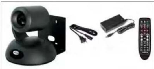
RoboSHOT 30 HDBT, North America, white - 999-9963-000W
■ RoboSHOT 30 HDBT Camera (998-9963-000 or 998-9963-000W)
■ Thin Profile Wall Mount with Mounting Hardware, black or white depending on camera color (535-2000-240 or 535-2000-240W)
■ Vaddio IR Remote Commander (998-2100-000)
■ 12 VDC, 3.0 Amp Switching Power Supply
■ AC Cord Set for North America
■ Quick-Start Guide (342-1219)
natural_image
Product photo of a black remote control device with attached cables and a remote control (no visible text or symbols)OR

natural_image
Product photo of a white remote control unit with attached cables and a remote control (no visible text or symbols)RoboSHOT 30 HDBT, Europe and UK, black - 999-9963-001
RoboSHOT 30 HDBT, Europe and UK, white - 999-9963-001W
■ RoboSHOT 30 HDBT Camera
- Thin Profile Wall Mount with Mounting Hardware, black or white depending on camera color (535-2000-240 or 535-2000-240W)
■ Vaddio IR Remote Commander (998-2100-000)
■ 12 VDC, 3.0 Amp Switching Power Supply
■ Euro Power Cord
■ UK Power Cord
■ Quick-Start Guide (342-1219)

natural_image
Product photo of a black remote control device with attached cables and a remote control (no visible text or symbols)OR

natural_image
Product photo of a white remote control unit with attached cables and a remote control (no visible text or symbols)RoboSHOT 30 HDBT, Australia and New Zealand, black - 999-9963-009
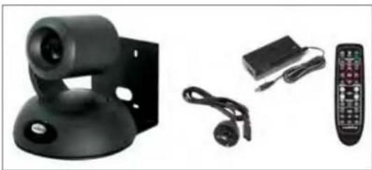
RoboSHOT 30 HDBT, Australia and New Zealand, white - 999-9963-009W
■ RoboSHOT 30 HDBT Camera
■ Thin Profile Wall Mount with Mounting Hardware, black or white depending on camera color (535-2000-240 or 535-2000-240W)
■ Vaddio IR Remote Commander (998-2100-000)
■ 12 VDC, 3.0 Amp Switching Power Supply
■ Power Cord for Australia and New Zealand
■ Quick-Start Guide (342-1219)
natural_image
Product photo of a black remote control device with attached cables and a remote control (no visible text or symbols)OR

natural_image
Product photo of a white remote control device with earphones, cables, and a remote control unit (no visible text or symbols)Download manuals, dimensional drawings, and other information from www.vaddio.com/support.
A Quick Look at the Camera
The RoboSHOT 12 and 30 models are similar. The RoboSHOT 12 is the camera on the left in the photo.
Front of the Camera

natural_image
Two black and silver cameras with lens modules, displayed on a stand (no visible text or symbols)■ Camera and Zoom Lens: The 12 and 30 models use different optical components.
- RoboSHOT 12 HDBT: 12X optical zoom lens (12X in Super-Wide mode and 10X in normal mode), Exmor 1/2.8-type, high-speed, low noise image sensor
- RoboSHOT 30 HDBT: 30X optical zoom lens, Exmor-R 1/2.8 type, backlit, high-speed, low-noise, image sensor
■ IR Sensors: Sensors in the front of the camera base receive signals from the remote. Make sure there's nothing directly in front of the camera base, and point the remote at the camera.
■ Status indicator: The multicolored LED indicates the camera's current state.
- Blue: Normal operation (blinks off momentarily when the camera receives a command from the remote)
- Purple: In standby mode or booting
- Yellow: Firmware update in progress
- Flashing purple: Error
- Red: On-air tally
Caution
Do not remove power or reset the camera while the indicator is yellow, showing a firmware upa progress. Interrupting a firmware update can make the camera unusable.
Back of the Camera
Rear panel connections are identical for both models.

From left to right:
■ Power connector: If not using a OneLINK HDMI extension module, use the 12 VDC, 3.0 A power supply shipped with the camera.
■ OneLINK HDBaseT/Network RJ-45 connector: If not using a OneLINK HDMI extension module, connect to the network.
■ HDMI connector: HDMI video output; connect to a display if not using a OneLINK HDMI extension module.
■ Video Resolution Select switch: Select the video output resolution.
■ Camera Settings DIP switches: Settings for IR remote frequency, baud rate and image flip.
Switch Settings
RoboSHOT cameras use a rotary switch to set the video resolution and a set of DIP switches that determine certain camera functions. A label on the bottom of the camera provides a quick reference for setting the switches.
Note
Set the switches appropriately before mounting the camera.
Video Resolution
Set the desired output resolution for the camera with the rotary switch. Switch positions 9 through D are not used.
| Switch position | Resolution |
| 0 720p/59.94 | |
| 1 1080i/59.94 | |
| 2 1080p/59.94 | |
| 3 720p/60 | |
| 4 1080i/60 | |
| 5 1080p/60 | |
| 6 720p/50 | |
| 7 1080i/50 | |
| 8 1080p/50 | |
| 9 – D Not used | |
| E 1080p/30 | |
| F 1080p/25 |
Camera Settings
Use the DIP switches to set camera behaviors.
Note
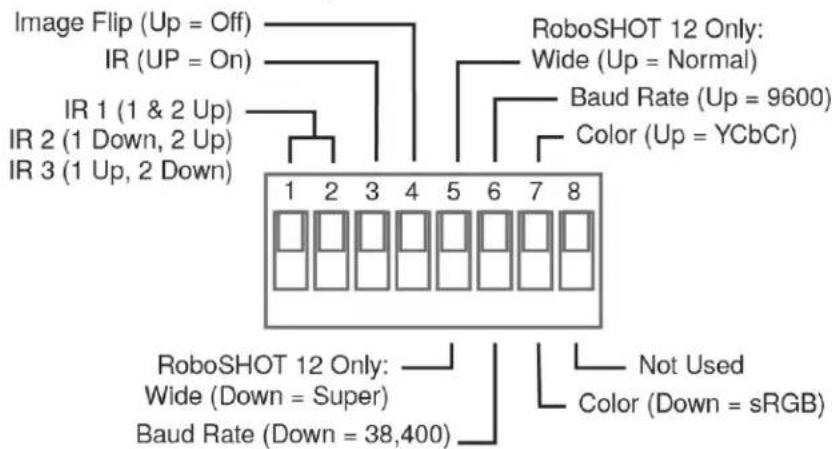
When the camera is right side up, switches are in their default positions when they are up.
IR Frequency Selection: The IR Remote Commander can control up to three cameras in the same room independently, if they are configured with different IR frequencies. Use switches 1 and 2 to select the frequency to identify the camera as camera 1, 2, or 3; then use the Camera Select buttons at the top of the remote to select the camera you want to control.
IR: Leave switch 3 in the default UP position if the IR remote will be used.
Image Flip: If mounting the camera upside-down, set switch 4 to the DOWN position: IMAGE FLIP ON.
Super Wide Mode (RoboSHOT 12 HDBT only): To use Super-wide mode, set switch 5 to the DOWN position. This gives 12X zoom with a 73° horizontal angle of view. Normal mode provides 10X zoom with a 67.2° horizontal field of view (HFOV).
Baud Rate: Set the baud rate for RS-232 communication using switch 6. Most applications use 9600 bps (switch 6 UP), which is recommended when using long cable runs. Use the 38,400 bps setting (switch 6 DOWN) for short control lines only.
Leave Switch 7 in the default UP position unless sRGB color output is needed.
Switch 8 is not currently used.
Pro Tip
Double-check switch settings before you mount the camera.
Installation
This section covers
■ Siting the camera
■ Installing the mount
■ Connecting the camera
■ Installing the camera
Before You Install the Camera
- Choose a camera mounting location that will optimize camera performance. Consider camera viewing angles, lighting conditions, line-of-sight obstructions, and in-wall obstructions where the camera is to be mounted.
■ If the IR Remote Commander will be used, ensure that nothing blocks the IR lens in the camera's base.
■ Ensure that the camera body can move freely and point away from the ceiling and lights.
■ Follow the installation instructions included with the camera mount.
Don't Void Your Warranty!
Caution
This product is for indoor use. Do not install it outdoors or in a humid environment without the protective enclosure. Do not allow it to come into contact with any liquid.
Use only the power supply included with this product. Using a different one will void the warran could create unsafe operating conditions or damage the product.
Do not install or operate this product if it has been dropped, damaged, or exposed to liquids. It is things happen, return it to Vaddio for safety and functional testing.
DomeVIEW enclosures are available to allow outdoor installation of RoboSHOT cameras. Learn more at www.vaddio.com/products.
Cabling Notes
Use Cat-5e or better cable and standard RJ-45 connectors (568B termination). We recommend using high-quality connectors and a high-quality crimping tool.
Caution
Check Cat-5 cables for continuity before using them. Using the wrong pin-out may damage the c system and void the warranty.
Note
Use standard RJ-45 connectors and a good crimping tool. Do not use pass-through RJ-45 connectors. Poorly crimped connectors can damage the connectors on the product, cause intermittent connections, and degrade signal quality. Test cable pin-outs and continuity before connecting them.

Intact - Contact fingers will make reliable contact with the cable connector
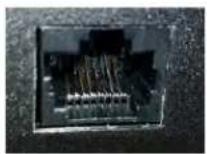
Damaged - Some contact fingers are bent and will NOT make reliable contact with the cable connector

Pro Tip
To prevent tragic mishaps, label both ends of every cable.
Installing the Wall Mount
All RoboSHOT cameras include a Thin Profile Wall Mount. Other mounting options are available as well. Contact us if you don't have the camera mount you need.
You can install the camera wall mount to a 2-gang wall box or directly to the drywall.
■ If you mount it to drywall, use the wall anchors provided with the wall mount.
■ If you mount it to a wall box, use the cover plate screws supplied with the wall box.

About Ceiling-Mounted Cameras
If you use an inverted mount, set the camera's Image Flip DIP switch ON for inverted operation. See Camera Settings for more information.
Basic Connection Diagram
The Quick-Start Guide for RoboSHOT HDBT Cameras provides additional information.

flowchart
graph LR
    A["Video Camera"] --> B["Server"]
    B --> C["Laptop"]
    D["Network"] <--> B
    E["Data Bus"] --> F["Video Panel"]
    F --> G["Computer"]
    style A fill:#f9f,stroke:#333
    style B fill:#ccf,stroke:#333
    style C fill:#cfc,stroke:#333
    style D fill:#fcc,stroke:#333
    style E fill:#cff,stroke:#333
    style F fill:#ffc,stroke:#333
    style G fill:#cfc,stroke:#333
Note
The OneLINK™ HDMI extension module is not required; the camera can be connected directly to network.
Options for Power and Other Connections
Connect the camera to a OneLINK HDMI camera extension module – a single Cat-5e (or better) cable provides power to the camera, along with HDBaseT network and video connectivity. Network, HDMI output, and RS-232 control are connected at the OneLINK module. Do not use the camera's 12 VDC power supply in this configuration.
Use the provided 12 VDC power supply – use the camera's OneLINK port to connect to the network, and connect the HDMI video output to a display.
Use a PoE+ power injector – Connect to the network through a PoE+ power injector, and connect the HDMI video output to a display. Do not use the camera's 12 VDC power supply in this configuration.
Installing the Camera
Caution
Before you start, be sure you can identify all cables correctly. Connecting a cable to the wrong result in equipment damage.
Caution
Check Cat-5 cables for continuity before using them. Using the wrong pin-out may damage the c system and void the warranty.
-
Route the cables to the camera location.
-
Route the cables through the mount, and install the mount on the wall or attach it to the wall box. Leave the screws loose enough to adjust the position of the mount.
-
Level the mount and tighten the mounting screws.
-
Check the level again.
-
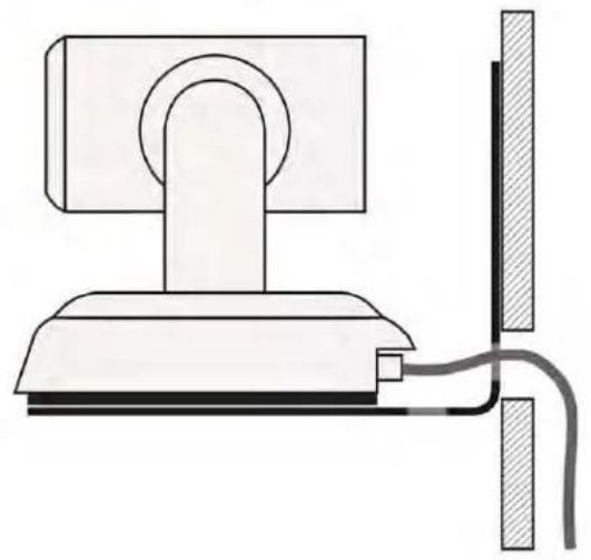
Connect the cables to the camera.
Caution
If using local power rather than connecting to a OneLINK extension module or using PoE+, u. power supply shipped with the camera. Using a different power supply may create an unsafe condition or damage the camera, and will void the warranty.
- Ensure that the video resolution switch and the DIP switches are set appropriately. See Switch Settings.
- Place the camera on the mount.
- Attach the camera to the mount using the 14 "-20 x .375 mounting screw supplied with the camera.
natural_image
Simple line drawing of a computer monitor with a cable and connector (no text or symbols)
natural_image
Simple line drawing of a computer monitor connected to a wall-mounted cable (no text or symbols)Image for illustration only; not to scale. Camera and mount details may differ.
Powering Up the Camera
Connect camera power.
The camera will wake up and initialize. This will take a few seconds. When the camera is initialized and ready, its front indicator is blue. At this point, it is ready to accept control information.
Note
Wait until the camera finishes initializing before trying to control it using the IR remote or other input.
Vaddio IR Remote Commander
The IR remote provides basic camera control for end users.
IR Remote Cheat Sheet
| What do you need to do? | Button(s) |
| Power on or standby Power (green button at top right) | |
| Select the camera to control (if the remote controls more than one) | Camera Select buttons 1 through 3 (second row on the remote) |
| Discover the camera's IP address | Data Screen button (top left) – press and hold for 3 seconds. |
| Move the camera Arrow buttons | and Home button (dark red) |
| Move the camera to a preset position | Position Preset buttons 1 through 6 (bottom two rows)You can access additional presets from the web interface. |
| Focus the camera Auto Focus | button (near arrow buttons)Manual Focus buttons Near and Far (below Zoom Speed buttons) |
| Control zoom speed | Zoom Speed buttons - Slow T and W, Fast T and W for telephoto and wide-angle modes (light gray) |
| Adjust for excess light behind the camera's subject | Back Light button (top center) |
IR Remote Details
The Vaddio remote provides the following functions:
Power - Switch the selected camera on or off.
Power indicator – Shows power on, IR transmission, and battery level.
Back Light – Use or turn off Back Light Compensation.
Data Screen – Display the camera's IP address and MAC address. Press this again to dismiss the display.
Camera Select – In multi-camera installations, selects the camera to be contr See Camera Settings for information on configuring the camera as camera 1, 2, or 3.
Pan/Tilt (arrow button) controls and Home button - Control the camera position.
Rev. Pan and Std. Pan- Control how the camera responds to the arrow by Helpful for ceiling-mounted cameras and for presenters who are controlling the camera.
Pan/Tilt Reset - Not used.
Auto Focus - Switch the camera to Auto-Focus mode.
Zoom Speed - Select Slow or Fast movements for telephoto and wide-angle
■ T (slow and fast) – Telephoto
■ W (slow and fast) – Wide-angle
Manual Focus - Switch the camera to Manual Focus mode.
Near (-) adjustment – Moves the focus nearer when in manual focus mode.
Far (+) adjustment – Moves the focus farther when in manual focus mode.
Position Presets 1 through 6 - Move the camera to a predefined position.
Preset - Save the camera's current position as one of the numbered presets.
Reset - Clear the saved position presets.
The web interface offers greater control over camera movements to presets (such as setting the speed for Tri-Synchronous Motion), and provides additional presets.
Storing a Preset Using the IR Remote Commander
Position the camera. Then hold down the Preset button and press one of the numbered preset buttons.
Clearing a Preset Using the IR Remote Commander
Press and hold the Reset button while pressing the preset number you want to clear.
Getting the Camera's IP Address
-
Press the Data Screen button on the remote. The room display presents the camera's IP address and MAC address.
-
Press the Data Screen button again to dismiss the information.
You can access the camera's web interface by entering the camera's IP address in the address bar of your browser.

Web Interface
The camera provides a web interface to allow control via an Ethernet network connection, using a browser. The web interface gives the user more control over the camera than the IR remote offers.
The web interface allows user-level camera control and password-protected administrative access to tasks such as setting passwords, changing the IP address, viewing diagnostics, and installing firmware updates.
- Administrative access – The default password is password. The admin has access to all pages of the web interface.
- User access – The default password is password. Only the camera control page is available with user-level access.
If the LAN has a DHCP server, the camera will get its IP address, gateway and routing information automatically and you will be able to browse to it. In the absence of a DHCP server, the camera's default IP address is 169.254.1.1 and its subnet mask is 255.255.255.0.
You can configure the camera's static IP address either through the network or from a computer connected directly to its Ethernet port. You may need a crossover cable.
Note
If the camera is used with a OneLINK device, the two devices have separate IP addresses and its own web interface.
Compatible Web Browsers
We have tested this product with these web browsers:
Chrome®
■ Microsoft® Internet Explorer®
■ Safari®
■ Firefox®
We test using the browser version available from the vendor at that time. Older versions of these browsers are likely to work, and other browsers may also work.
User Access
If the admin sets up automatic guest access, no login is needed – the system starts at the Camera Control page, rather than the login page. The administrative login dialog is accessible from the Camera Control page, to allow access to administrative tasks.

Administrative Access
If you are on the Camera Control screen and no other screens are available, you're logged in at the user level, or guest access is enabled and you're not logged on at all. Use the Admin button to open the login screen.
When you log in as Admin, all the admin menu buttons appear on the left side of the screen. In addition to Camera Controls, you also have access to:
- Camera Settings – Additional control over camera behavior related to camera movement and color management.
■ Streaming - Set up IP (H.264) streaming.
■ Room Labels – Add helpful information the web interface screens, such as conference room name and the in-house number for AV assistance.
■ Networking – Ethernet configuration.
■ Security – Set passwords and manage guest access.
■ Diagnostics – Access to logs for troubleshooting.
■ System – Reboot, restore defaults, view switch settings, and run updates.
■ Help – Tech support contact information.
Web Interface Cheat Sheet
Where to find the camera controls you need right now.
| What do you need? Go to this screen | |
| Camera operation■ Move or zoom the camera■ Set the speed for pan, tilt, or zoom motions■ Focus the camera (Focus button reveals the focus control)■ Move to a camera preset■ Put the camera into or bring it out of standby mode | Camera Controls |
| Camera behavior■ Set motors for inverted operation (Settings button reveals the control)■ Set or clear camera presets■ Select the appropriate lighting adjustments (CCU Scenes section) | Camera Controls |
| Camera behavior■ Define custom lighting adjustments (CCU scenes)■ Specify whether to use automated adjustments (auto-iris, auto balance, backlight compensation) | Camera Settings white |
| Camera adjustments■ Color settings (Iris, iris gain, red gain, blue gain, detail, chroma, gamma)■ Store and label custom color settings as CCU scenes■ Specify global speed settings for camera movements that do Tri-Synchronous Motion | Camera Settings not use |
| Access management■ Guest access■ Account passwords | Security |
| IP streaming settings■ Quality■ Resolution■ Frame rate■ Streaming URL and path | Streaming |
| IP settings■ Hostname■ DHCP or static addressing■ Static: IP address, subnet mask, gateway | Networking |
| Information about the camera's current hardware switch settings | System |
| Time zone and NTP server (source for system time/date) Networking | |
| Diagnostic logs Diagnostics | |
| Information about the camera location Room Labels | |
| Helpdesk phone number for end users Room Labels | |
| Vaddio Technical Support contact information Help | |
Web Tasks for All Users: Controlling the Camera
CAMERA CONTROLS PAGE
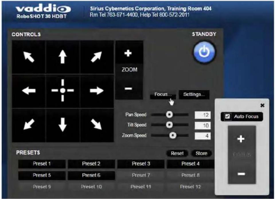
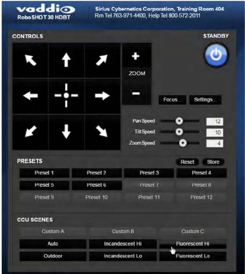
The Camera Controls page provides most of the same controls as the IR Remote Commander, along with some that are not available from the remote:
■ Pan, tilt, zoom, or return to "home" position
■ Put the camera in standby or bring it back to the ready state
■ Set speeds for camera movements
■ Focus manually or set auto-focus
■ Set or move to camera presets
■ Select one of the stored lighting adjustments
■ Set the way the camera responds to the arrow buttons on the remote
Since the web interface is specific to the camera you are working with, it does not offer camera selection.
Note
Administrators can also customize the camera's home position from this page.

Switching the Camera Off or On
Use the Standby button to switch between low-power (standby) and ready states.
On entering standby mode, the camera moves to its standby position.


Moving the Camera
Use the arrow buttons for camera pan and tilt. The center button moves the camera to the home position.
Zooming In or Out
Use the Zoom + button to zoom in and the Zoom - button to zoom out.

Changing the Focus
Open the Focus control to select Auto-focus, or set manual focus with the + (near) and - (far) buttons. I know you get this, but I'm going to say it anyway: The + and - buttons don't work when the Auto Focus box is checked.
Moving the Camera to a Preset Position
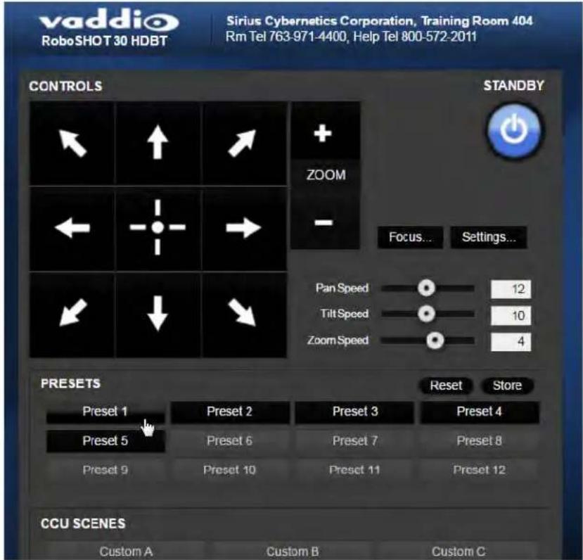
Use the numbered Preset buttons to move the camera to any of its programmed positions. If you select a preset that has not yet been programmed, nothing happens.
Selecting the Appropriate Color Settings
Adjust the camera for the lighting in use by selecting the CCU scene that best fits your environment. The technical folks at Vaddio (Scott, to be specific) have already set up presets for common lighting scenarios – Incandescent Hi, Incandescent Lo, Fluorescent Hi, Fluorescent Lo and Outdoor. The Auto setting allows the camera to determine the appropriate adjustments.
The first three settings in this area of the web interface (initially labeled Custom A through Custom C) can be set and renamed from the Camera Settings page, accessible to admin users.
Storing a Camera Preset
- Set up the camera shot, then use the Store button to open the Store Preset box.
- Click one of the numbered preset buttons.
- Check Save with Tri-Sync to allow the pan, tilt, and zoom motors to move simultaneously.
- If necessary, use the speed slider to set Tri-Sync speed. For tight shots, slower is better.
- To save the current color settings along with the camera position, check Save with current color settings.
- Save the preset.
Note:
The Tri-Synchronous Motion algorithm works best for on-air shots requiring significant movement in than one axis. It is not useful when moving the camera less than 10^ or when the camera is You may need to experiment with the Tri-Sync setting.

Changing the Speed of Camera Movements
Use the speed sliders to adjust the speed of movements that you control with the buttons for pan, tilt and zoom. For tight shots, slower is usually better.

Setting Pan Direction
By default, the arrow buttons move the camera in the direction that viewers at the far end would see. If you face the camera and use the left arrow button, the camera pans to your right.
To switch the camera pan direction to the near end point of view, use the Settings button to open the pan and tilt direction box. Then set Pan Direction to Inverted.
Setting Tilt Direction
Tilt direction can also be normal or inverted. Set it according to what will be the most intuitive for the people most likely to be controlling the camera.

Web Tasks for Administrators: Setting a Custom Home Position
CAMERA SETTINGS PAGE
If you are logged in as admin, you can set a custom Home preset in place of the camera's default home position (0° pan and 0° tilt). The Home preset is not available in the Store Preset box if you are not logged as admin.
Set up the shot and store the custom Home position as you would for any other preset. Like other presets, the custom Home preset can include color, speed, and Tri-Synchronous Motion settings.

Web Tasks for Administrators: Managing Access and Passwords
SECURITY PAGE
Things you can do on this page:
- Allow people to access the Camera Control screen without logging on (Allow Guest Access)
■ Set whether inactive sessions log off automatically or not (Automatically Expire Idle Sessions)
■ Change the password for the admin account
■ Change the password for the user account
Note
For best security, Vaddio strongly recommends changing the user and admin passwords from the default. Using the default passwords leaves the product vulnerable to tampering.

Web Tasks for Administrators: Adding Room Information to the Web Interface
ROOM LABELS PAGE
To display your company name, conference room name and phone number, and the number for meeting hosts to call for in-house A/V support, enter this information on the Room Labels page.
![vaddio RoboSHOT 30 HDBT Sirius Cybernetics Corporation, Training Room 404 Rm Tel 763-971-4400, Help Tel 800-572-2011 Camera Controls Camera Settings Streaming ROOM LABELS Company Name Sirius Cybernetics Corporation Room Name Training Room 404 Room Phone Number 763-971-4400 Help Phone Number [800-572-2011]](/content/2026/05/1069306/images/c4d2afc52dc0b18ec200500eb8230ebaa7208edce46e9027af87139984ffe566.jpg)
Web Tasks for Administrators: Configuring Network Settings
NETWORKING PAGE
Things you can do on this page:
■ Specify time zone and NTP server
- Assign the camera's hostname
■ Specify DHCP or static IP address
■ Set up other networking information
DHCP is the default setting, but the camera will use the default address of 169.254.1.1 if no DHCP server is available.
You will only be able to enter the IP address, subnet mask, and gateway if you set IP Address to Static.
Caution
Do not change DHCP/Static addressing, IP address, subnet mask, or gateway unless you are very with the characteristics and configuration of the network where you install the camera. Errors in r configuration can make the camera and its IP stream inaccessible from the network.

Specifying Time Zone and NTP Server
- To make the time zone and NTP server editable, enable Automatic NTP Updating.
- Select the desired time zone from the list.
- If desired, specify the NTP server to use. Otherwise, use the default.
You may need to refresh the system time display.

Web Tasks for Administrators: Configuring Streaming Settings
STREAMING PAGE
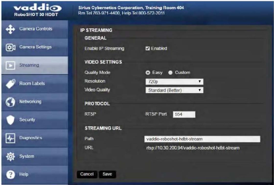
Things you can do on this page:
■ Enable or disable IP streaming
■ Set the resolution, video quality, and frame rate for IP streaming
■ Specify the IP streaming port and path/URL
The camera uses the RTSP protocol for H.264 streaming. Resolutions range from 1080p down to CIF; frame rates are 30/25/15 for 1080p and 60/30/25/15 for all other resolutions.
Enabling or Disabling Streaming
IP streaming is enabled by default. Use the Enable IP Streaming checkbox to change this. Save the change before you leave this page of the web interface.
Editing IP Streaming Settings
Note
The web interface presents all the possible streaming resolutions values, but the IP stream cannot higher than the value set with the video resolution switch on the back of the camera. (See Video Resolution for information on setting the switch.) If the selected value is out of range, the camera will adjust the streaming resolution.
If you are not sure about these settings, start with the defaults.
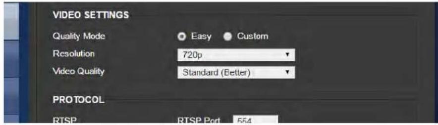
- Select the video Quality Mode: Easy or Custom. Easy automatically sets the recommended frame rate; Custom provides additional control.
- Select the desired IP streaming resolution.
- Easy quality mode only: Select Video Quality.
- Custom quality mode only: Select the desired IP streaming frame rate.
- Custom quality mode only: Select Constant or Variable bit rate.
- Custom quality mode, Variable bit rate only: Set the Quality (Quantization) slider.
- Save your changes.


Advanced IP Streaming Settings
RTSP port: Vaddio strongly recommends using the default RTSP port number unless you need to change it.
Streaming URL: If necessary, edit the path to change the portion of the streaming URL that appears after the IP address.
Save your changes.
Web Tasks for Administrators: Setting Camera Behaviors and Adjustments
CAMERA SETTINGS PAGE
Things you can do on this page:
■ Set up and name custom color and lighting settings.
■ Set the pan, tilt, and zoom speeds that will be used for movements other than recalling presets saved with Tri-Synchronous Motion.

Setting Up Custom Color and Lighting Settings
You can customize the camera's color and lighting settings as a one-time adjustment, or save the adjustments as one of the three custom CCU scenes.
-
Click any of the CCU scene buttons to load one of the CCU scenes into the camera, then fine-tune it as needed using the Color Settings controls.
-
To allow the camera to compensate automatically for the light level, check the Auto Iris box. Leave it unchecked to adjust iris and gain manually.
-
Auto Iris adjustments – these adjust contrast between the brightest and darkest areas of the image.
■ If there is bright light behind the main subject of the shot, check the box for Back Light
Compensation.
■ To increase contrast between the brightest and darkest areas, check the box for Wide Dynamic Range.
Note
Because Backlight Compensation reduces the contrast between extremes and Wide Dynamic Range increases it, they cannot be used together.
-
To allow the camera to adjust the white balance automatically, check the Auto White Balance box. Leave it unchecked to adjust red gain and blue gain manually.
-
Detail - adjust the slider as required for the right image sharpness.
Note
If the video looks grainy or “noisy,” try a lower Detail setting. As in conversation, too much
- Chroma - adjust the slider as needed for the right level of color intensity.
- Gamma - adjust the slider as needed for the desired range between bright areas and shadows.
- When the scene looks the way you want it to, click Store CCU Scene.
- In the Store CCU Scene dialog box, select which custom scene to store (Custom A, B, or C) and optionally give it a descriptive name. You can rename it later if necessary.
- Name and save your custom scene.
If you make a change that you don't like, start over by selecting and then deselecting Auto White Balance.
Renaming a Custom CCU Scene
In the Custom CCU Scene Labels section, edit the text for the desired CCU scene label.
Setting Pan, Tilt, and Zoom Speeds
In the Global Preset Non-Tri-Sync Speeds section, set the speeds for movements to presets that do not use Tri-Synchronous Motion.
Web Tasks for Administrators: Rebooting, Updating, and Resetting
SYSTEM PAGE
Things you can do on this page:
■ Reboot the camera
■ Back up or restore the camera configuration
■ Run a firmware update
■ Set the camera back to its original factory settings
- Read (but not change) the current settings of the switches on the back of the camera
■ Set the camera's soft DIP switch to specify the LED color scheme

Rebooting the Camera
This can help if the camera stops responding as you expect. In the System Utilities section, click Reboot.
Saving (Exporting) or Restoring (Importing) a Configuration
If you need to configure several cameras the same way, you can configure the first one, export its configuration (Export Data button), and then import the configuration to the other cameras (Import Data button in each camera's web interface). The export downloads to your computer as a .dat file. The filename is the camera's hostname.
Certain information is not included in the configuration, such as hostname and passwords.
Note
The camera cannot import a .dat file that was exported from a camera using a different version
Starting a Firmware Update
If you prefer more detail than this procedure, please refer to the Release Notes for step-by-step instructions with screen shots.
- Locate and download the firmware and its release notes.
- Select Choose File, then browse to the firmware that you downloaded and select it. The filename ends with .p7m.
- Click Begin Firmware Update.
- READ the information in the Confirm dialog box and be sure you understand it. It may seem boring, but it could save you some time and aggravation.
- When you are ready to start the update, click Continue. A progress message box opens and the indicator light on the front of the camera turns yellow to show the firmware update is in progress. If the update process presents warnings or error messages, read them carefully.
The process may take a few minutes.
Caution
Ensure that the camera stays powered on and connected to the network during the update. Inter update could make the camera unusable.
The camera reboots when the update is complete.
Restoring Factory Settings
Sometimes it's easiest to just start over. To restore the original factory settings...click Restore Factory Settings. This will overwrite anything you have customized, such as custom CCU scenes and presets.
Reading the Camera's Back Panel Switches
Open the DIP Switches tab to see the camera's current switch settings.
Note:
Sorry, you have to physically move the switches on the back of the camera if you need to ch hardware settings.
Setting the LED Color Scheme
DIP SWITCHES TAB
Use the camera's soft DIP switch to set the LED color scheme (Pro A/V or UCC). At this time, they are functionally identical on this camera.

Web Tasks for Administrators: Contacting Vaddio Technical Support
HELP PAGE
If you can't resolve an issue using your troubleshooting skills (or the Troubleshooting table in this manual), we are here to help.
You'll find information for contacting Vaddio Technical Support on the Help page.

Web Tasks for Administrators: Viewing Diagnostic Logs
DIAGNOSTICS PAGE
If you encounter a problem that you can't solve, your Vaddio technical support representative may ask you to download and email the log file available from the Diagnostics page.
![vaddio RoboSHOT 30 HDBT Sirius Cybernetics Corporation, Training Room 404 Rm Tel 763-971-4400, Help Tel 800-572-2011 Catalog Camera Controls Camera Settings Streaming Room Labels Networking Security Diagnostics System Help Logout DIAGNOSTICS Jan 18 17:36 01 vaddio-roboshot-hdbt-D8-80-39-A4-F7-98 [ 0.000014] sched_clock_64 bits at 333MHz, resolution jns, wraps every Jan 18 17:36 01 vaddio-roboshot-hdbt-D8-80-39-A4-F7-98 [ 0.000286] ps7-ttc #0 at d8804000, irq=43 Jan 18 17:36 01 vaddio-roboshot-hdbt-D8-80-39-A4-F7-98 [ 0.000690] Calibrating delay loop_ 1332.01 BogoMIPS (lpj=6660096) Jan 18 17:36 01 vaddio-roboshot-hdbt-D8-80-39-A4-F7-98 [ 0.090233] pid_max: default: 32768 minimum: 301 Jan 18 17:36 01 vaddio-roboshot-hdbt-D8-80-39-A4-F7-98 [ 0.090431] Mount-cache hash table entries: 1024 (order: 0. 4096 bytes) Jan 18 17:36 01 vaddio-roboshot-hdbt-D8-80-39-A4-F7-98 [ 0.090448] Mountpoint-cache hash table entries: 1024 (order: 0. 4096 by) Jan 18 17:36 01 vaddio-roboshot-hdbt-D8-80-39-A4-F7-98 [ 0.091222] CPU: Testing write buffer coherency: ok Jan 18 17:36 01 vaddio-roboshot-hdbt-D8-80-39-A4-F7-98 [ 0.091533] missing device node for CPU 0 Jan 18 17:36 01 vaddio-roboshot-hdbt-D8-80-39-A4-F7-98 [ 0.091561] missing device node for CPU 1 Jan 18 17:36 01 vaddio-roboshot-hdbt-D8-80-39-A4-F7-98 [ 0.091576] CPU: thread -1, cpu 0, socket 0, mpidr 8000000 Jan 18 17:36 01 vaddio-roboshot-hdbt-D8-80-39-A4-F7-98 [ 0.091623] Setting up static identity map for 0x345a28 - 0x345a5c Jan 18 17:36 01 vaddio-roboshot-hdbt-D8-80-39-A4-F7-98 [ 0.091856] L310 cache controller enabled Jan 18 17:36 01 vaddio-roboshot-hdbt-D8-80-39-A4-F7-98 [ 0.091874] I2xO: 8 ways, CACHE_ID 0x41000c8, AUX_CTRL 0x72760 Jan 18 17:36 01 vaddio-roboshot-hdbt-D8-80-39-A4-F7-98 [ 0.150222] Brought up 1 CPUs Jan 18 17:36 01 vaddio-roboshot-hdbt-D8-80-39-A4-F7-98 [ 0.150232] SMP: Total of 1 processors activated Jan 18 17:36 01 vaddio-roboshot-hdbt-D8-80-39-A4-F7-98 [ 0.150241] CPU: All CPU(s) started in SVC mode. Jan 18 17:36 01 vaddio-roboshot-hdbt-D8-80-39-A4-F7-98 [ 0.150780] devtmpfs: initialized Jan 18 17:36 01 vaddio-roboshot-hdbt-D8-80-39-A4-F7-98 [ 0.152785] VFP support v0.3 implementor 41 architecture 3 part 30 varia Jan 18 17:36 01 vaddio-roboshot-hdbt-D8-80-39-A4-F7-98 [ 0.153755] regulator-dummy: no parameters Jan 18 17:36 01 vaddio-roboshot-hdbt-D8-80-39-A4-F7-98 [ 0.154358] NET Registered protocol family 16 Jan 18 17:36 01 vaddio-roboshot-hdbt-D8-80-39-A4-F7-98 [ 0.155366] DMA: preallocated 256 KiB pool for atomic coherent allocation Jan 18 17:36 01 vaddio-roboshot-hdbt-D8-80-39-A4-F7-98 [ 0.165103] syscon f800000, ps7-slicr. regmap [mem 0xf900000-0xf/800 Jan 18 17:36 01 vaddio-roboshot-hdbt-D8-80-39-A4-F7-98 [ 0.173546] hw-breakpoint: found 5 (+1 reserved) breakpoint and 1 watch Jan 18 17:36 01 vaddio-roboshot-hdbt-D8-80-39-A4-F7-98 [ 0.173561] hw-breakpoint: maximum watchpoint size is 4 bytes. Jan 18 17:36 01 vaddio-roboshot-hdbt-D8-80-39-A4-F7-98 [ 0.173683] zynq-ocm f80c, ooo, ps7-oomc: ZYNQ OCM pool: 256 KiB @ Jan 18 17:36 01 vaddio-roboshot-hdbt-D8-80-39-A4-F7-98 [ 0.183665] bio: create slab at O Jan 18 17:36 01 vaddio-roboshot-hdbt-D8-80-39-A4-F7-98 [ 0.187765] Switched to clocksource arm_global_timer Jan 18 17:36 01 vaddio-roboshot-hdbt-D8-80-39-A4-F7-98 [ 0.190982] NET Registered protocol family 2 Jan 18 17:36 01 vaddio-roboshot-hdbt-D8-80-39-A4-F7-98 [ 0.191543] TCP established hash table entries: 4Q96 (order: 2, 163B4 by) Jan 18 17:36 01 vaddio-roboshot-hdbt-D8-80-39-A4-F7-98 [ 0.191599] TCP bind hash table entries: 4Q96 (order: 3, 327B8 bytes) Jan 18 17:36 01 vaddio-roboshot-hdbt-D8-80-39-A4-F7-98 [ 0.191677] TCP: Hash tables configured (established FOPs bind FOPs) Jan 18 17:36 01 vaddio-roboshot-hdbt-D8-80-39-A4-F7-98 [ 0.191724] TCP: reno registered Download Refresh Clear Restore](/content/2026/05/1069306/images/02922c4dad2ee87af981f534109a5361423dee69f31520386605fa50c615b3f3.jpg)
Telnet Serial Command API
The Vaddio serial command protocol is a high-level, text-based command line interface supported via Telnet session on the camera. The API is accessed by a telnet client on the Ethernet port; the default Telnet port is 23. Telnet sessions require the administrator account login.
The command application protocol interface is intended to allow external device such as AMX or Crestron to control the camera. The protocol is based upon ASCII format following the VT100 terminal emulation standard and uses an intuitive text command nomenclature for ease of use.
General format usage follows a get/set structure. Usage examples for each type are:
Set Example
COMMAND: > camera pan right
RESPONSE: > OK
Get Example
COMMAND: > camera ccu get iris
RESPONSE: > iris 11
Syntax Error Example
COMMAND: > camera right pan
RESPONSE: > ERROR

Using a question mark as a command parameter will bring up a list of available commands for the menu you are in.
Things to know about control via Telnet session:
■ Command lines are terminated with a carriage return.
■ All ASCII characters (including carriage returns) are echoed to the terminal program and appended with the VT100 string ESC[J (hex 1B 5B 4A), which most terminal programs automatically strip.
■ CTRL-5 Clears the current serial buffer on the device.
Typographical conventions:
■ {x | y | z} - Choose x, y, or z.
-
■ < x - y > - Valid range of values is from x through y.
■ [optional] – Parameter is not required.
camera home
Moves the camera to its home position.
| Synopsis camera home | |
| Example | >camera homeOK> |
camera pan
Moves the camera horizontally.
| Synopsis camera pan { left [] | right [] | stop } | ||
| Options | left | Moves the camera left. |
| right | Moves the camera right. | |
| speed <1 - 24> Optional: | Specifies the pan speed as an integer (1 to 24). Default speed is 12. | |
| stop | Stops the camera's horizontal movement. | |
| Examples | >camera pan leftOK>Pans the camera left at the default speed.>camera pan right 20OK>Pans the camera right using a speed of 20.>camera pan stopOK>Stops the camera's horizontal motion. | |
camera tilt
Moves the camera vertically.
| Synopsis camera tilt{ up [] | down [] | stop } | ||
| Options | up | Moves the camera up. |
| down | Moves the camera down. | |
| speed <1 - 20> Optional: | Specifies the tilt speed as an integer (1 to 20). Default speed is 10. | |
| stop | Stops the camera's vertical movement. | |
| Examples | >camera tilt upOK>Tilts the camera up at the default speed.>camera tilt down 20OK>Tilts the camera down using a speed of 20.>camera tilt stopOK>Stops the camera's vertical motion, | |
camera zoom
Moves the camera in toward the subject or out away from the subject.
| Synopsis camera zoom { in [] | out [] | stop } | ||
| Options | in | Moves the camera in. |
| out | Moves the camera out. | |
| speed [1 - 7] Optional: Sp | Specifies the zoom speed as an integer (1 to 7). Default speed is 3. | |
| stop | Stops the camera's zoom movement. | |
| Examples | >camera zoom inOK>Zooms the camera in at the default speed.>camera zoom out 7OK>Zooms the camera out using a speed of 7.>camera zoom stopOK>Stops the camera's zoom motion. | |
camera focus
Changes the camera focus.
| Synopsis camera focus {near [] | far [] stop | mode {get | auto | manual}} | ||
| Options | near | Brings the focus nearer to the camera. Can only be used when camera is in manual mode. |
| far | Moves the focus farther from the camera. Can only be used when camera is in manual mode. | |
| speed <1 - 8> Optional: integer | (1 to 8) specifies the focus speed. | |
| mode {get | auto | manual} | Returns the current focus mode, or specifies automatic or manual focus. | |
| stop | Stops the camera's focus movement. | |
| Examples | camera focus nearOK>Brings the focus near at the default speed.camera focus far 7OK>Moves the focus farther from the camera at a speed of 7.camera focus mode getauto_focus: onOK>Returns the current focus mode. | |
camera preset
Moves the camera to the specified preset, or stores the current camera position and optionally CCU information, either with or without specifying that Tri-Synchronous Motion is to be used when moving to this position.
Note
This command corresponds to the CAM_Memory commands in the RS-232 command set.
| Synopsis camera | preset { recall | store} <1 - 16> [tri-sync <1 - 24>] [save-ccu] | |
| Options recall | <1 - 16> Moves the camera to the specified preset, using Tri-Synchronous Motion if this was saved with the preset. If CCU information was saved with the preset, the camera switches to the CCU setting associated with the preset. | |
| store <1 - 16> Stores the current camera position as the specified preset. | ||
| tri-sync <1 - 24> Optional: Specifies that the camera uses Tri-Synchronous Motion to move to this position, using the specified speed. | ||
| save-ccu | Optional: Saves the current CCU settings as part of the preset. If not specified, the last color settings are used when recalled. | |
| Examples | >camera preset recall 3OK>Moves the camera to preset 3.>camera preset store 1OK>Saves the camera's current position as preset 1.>camera preset store 4 tri-sync 15OK>Stores the camera's current position as preset 4. The camera will use Tri-Synchronous Motion at speed 15 when it is recalled to this preset.>camera preset store 2 tri-sync 10 save-ccuOK>Stores the camera's current position as preset 2. The camera apply the current CCU settings and use Tri-Synchronous Motion at speed 15 when it is recalled to this preset. | |
camera ccu get
Returns or sets CCU (lighting) information.
| Synopsis camera | ccu get | |
Options | auto_white_balance | Returns the current state of the auto white balance setting (on or off). |
| red_gain | Returns the red gain value as an integer (0 to 255). | |
| blue_gain | Returns the blue gain value as an integer (0 to 255). | |
| backlight_compensation | Returns the current state of the backlight compensation setting (on or off). | |
| iris | Returns the iris value as an integer (0 to 11). | |
| auto_iris | Returns the current auto-iris state (on or off). | |
| gain | Returns the gain value as an integer (0 to 11). | |
| detail | Returns the detail value as an integer (0 to 15). | |
| chroma | Returns the chroma value as an integer (0 to 14). | |
| wide_dynamic_range | Returns the current state for Wide Dynamic Range (on or off). | |
| all | Returns all current CCU settings. | |
| Examples | >camera ccu get irisiris 6OK>Returns the current iris value.>camera ccu get red_gainred_gain 201OK>Returns the current red gain value.>camera ccu get allauto_iris onauto_white_balance onbacklight_compensation offblue_gain 193chroma 2detail 8gain 3iris 11red_gain 201wide_dynamic_range offOK>Returns all current CCU settings. | |
camera ccu set
Sets the specified CCU (lighting) information.
| Synopsis camera | ccu set | |
Options auto_white | te_balance {on| off} | Sets the current state of the auto white balance setting (on or off). Auto white balance overrides red gain and blue gain manual settings. |
| red_gain <0 - 255> Sets | the red gain value as an integer (0 to 255). Can only be used when auto white balance is off. | |
| blue_gain <0 - 255> Sets | is the blue gain value as an integer (0 to 255). Can only be used when auto white balance is off. | |
| backlight_compensation {on | off} | Sets the current state of the backlight compensation setting (on or off). Can only be used when wide dynamic range mode is off. | |
| iris <0 - 11> Sets the iris value as an integer (0 to 11). Can only be used when auto-iris is off. | ||
| auto_iris {on | off} Sets | the auto-iris state (on or off). Auto-iris disables manual iris and gain when it is on. | |
| gain <0 - 11> Sets gain | value as an integer (0 to 11). Can only be used when auto-iris is off. | |
| detail <0 - 15> Sets the | detail value as an integer (0 to 15). | |
| chroma <0 - 14> Sets the | chroma value as an integer (0 to 14). | |
| wide_dynamic_range {on| off} | Sets Wide Dynamic Range mode on or off. Can only be used when backlight compensation is off. | |
| Examples | >camera ccu set auto_iris offOK>Turns off auto-iris mode, returning the camera to manual iris control.>camera ccu set red_gain 10OK>Sets the red gain value to 10. | |
camera ccu scene
Stores the current CCU scene or recalls the specified ccu scene.
| Synopsis camera | ccu scene {recall {factory <1 - 6> | custom <1 - 3>} | store custom <1 - 3>} | |
| Options recall | factory <1 - 6>recall custom <1 - 3> | Recalls the camera to the specified scene (factory 1 - 6 or custom 1 - 3). |
| store custom <1-3> | Saves the current scene as the specified custom scene. | |
| Examples | >camera ccu scene recall factory 2OK>Sets the camera to use factory CCU scene 2.>camera ccu scene store custom 1OK>Saves the current CCU scene as custom CCU scene 1. | |
camera standby
Set or change camera standby status.
| Synopsis camera standby {off | on | toggle} | ||
| Parameters | off | Brings the camera out of standby (sleep) mode. |
| on Stops video and puts the | camera in standby mode. | |
| toggle Changes the camera | 's standby state - if it was not in standby mode, it enters standby; if it was in standby mode, it "wakes up." | |
| get | Returns the camera's current standby state (on or off). | |
| Examples | camera standby offBrings the camera out of standby mode. | |
| camera standby onPuts the camera in standby mode. | ||
streaming settings get
Retrieves IP streaming settings. These are configured in the web interface.
| Synopsis streaming settings get | ||
| Parameters | IP Custom_Frame_Rate | Frame rate selected in Custom quality mode. |
| IP Custom_Resolution | Resolution selected in Custom quality mode. | |
| IP Enabled | True if IP streaming is enabled, False if it is not | |
| IP Port | The RTSP port number used for IP streaming. Default is 554. | |
| IP Preset_Quality | Video quality selected in Easy video quality mode. | |
| IP Preset_Resolution | Resolution selected in Easy video quality mode. | |
| IP Protocol | The IP streaming protocol in use. | |
| IP URL | The URL where the stream is available. | |
| IP Video_Mode | Video quality mode selected (preset or custom) | |
| Example | >streaming settings getIP Custom_Frame_Rate 30IP Custom_Resolution 1080pIP Enabled trueIP Port 554IP Preset_Quality Standard (Better)IP Preset_Resolution 720pIP Protocol RTSPIP URL vaddio-roboshot-hdbt-streamIP Video_Mode presetReturns the current streaming settings. | |
network settings get
Returns the current network settings for MAC address, IP address, subnet mask, and gateway.
| Synopsis | network settings get |
| Example | > network settings getName eth0:WANMAC Address 00:1E:C0:F6:CA:7BIP Address 192.168.1.67Netmask 255.255.255.0VLAN DisabledGateway 192.168.1.254OK> |
network ping
Sends an ICMP ECHO_REQUEST to the specified IP address or hostname.
| Synopsis network | ping [count] [size] | |
| Options | The number of ECHO_REQUEST packets to send. Default is five packets. | |
| The size of each ECHO_REQUEST packet. Default is 56 bytes. | ||
| The IP address where the ECHO_REQUEST packets will be sent. | ||
| Examples | >network ping 192.168.1.66PING 192.168.1.66 (192.168.1.66): 56 data bytes64 bytes from 192.168.1.66: seq=0 ttl=64 time=0.476 ms64 bytes from 192.168.1.66: seq=1 ttl=64 time=0.416 ms64 bytes from 192.168.1.66: seq=2 ttl=64 time=0.410 ms64 bytes from 192.168.1.66: seq=3 ttl=64 time=0.410 ms64 bytes from 192.168.1.66: seq=4 ttl=64 time=3.112 ms--- 192.168.1.66 ping statistics ---5 packets transmitted, 5 packets received, 0% packet lossround-trip min/avg/max = 0.410/0.964/3.112 ms>Sends five ECHO_REQUEST packets of 56 bytes each to the host at 192.168.1.66. | |
| >network ping count 10 size 100 192.168.1.1Sends 10 ECHO_REQUEST packets of 100 bytes each to the host at 192 The command returns data in the same form as above. | ||
system reboot
Reboots the system either immediately or after the specified delay. Note that a reboot is required when resetting the system to factory defaults (system factory-reset).
| Synopsis system reboot [] | ||
| Options | The number of seconds to delay the reboot. | |
| Examples | >system rebootOK>The system is going down for reboot NOW! roboshot-hdbt-D8-80-39-62-A7-C5Reboots the system immediately.>system reboot 30Reboots the system in 30 seconds. The response is in the same form; the system message appears at the end of the delay. | |
system factory-reset
Gets or sets the factory reset status. When the factory reset status is on, the system resets to factory defaults on reboot.
| Synopsis system factory-reset {get | on | off} | ||
| Options | get | Returns the camera's current factory reset status. |
| on | Enables factory reset on reboot. | |
| off | Disables factory reset on reboot. | |
| Examples | >system factory-reset getfactory-reset (software): offfactory-reset (hardware): offOK>Returns the factory reset status.This evaluates the most recent system factory-reset on or off comma one has been received, then reads the rear panel DIP switches and return status on if they are all in the down position.>system factory-reset onfactory-reset (software): onfactory-reset (hardware): offOK>Enables factory reset upon reboot.NoteThis command does not initiate a factory reset. The factory reset next reboot. | |
sleep
Pauses for the specified number of milliseconds before evaluating and executing the next command.
| Synopsis sleep | ||
| Options | The number of milliseconds | (1 to 10000) to pause. |
| Example | >sleep 7000OK>Pause for 7 seconds (7000 milliseconds) before returning. | |
history
Returns the most recently issued commands from the current Telnet session. Since many of the programs read user input a line at a time, the command history is used to keep track of these lines and recall historic information.
| Synopsis history | ||
| OptionsInteger value specifying themaximum number of commands to return. | ||
| Examples | historyDisplays the current command buffer.history 5Sets the history command buffer to remember the last 5 unique entries. | |
| Additional information You | can navigate the command history using the up and down arrow keys.This command supports the expansion functionality from which previous commands can be recalled from within a single session. History expansion is performed immediately after a complete line is read.Examples of history expansion:* !! Substitute the last command line.* !4 Substitute the 4th command line (absolute as per 'history' command)* !-3 Substitute the command line entered 3 lines before (relative) | |
 | ||
version
Returns the current firmware version.
| Synopsis version | |
| Example | >versionCommit: d033ddb2378357a871011eb820706dcaa64ec0e2HDLink: TX4.6.1x0.03PSoC Version: 1.1Pan Motor Version: 0.2.4772Sensor Version: 06.00System Version: RoboSHOT HDBT 1.0.0Tilt Motor Version: 0.2.4772OKReturns current firmware version information. |
help
Displays an overview of the CLI syntax.
| Synopsis help | |
| Example | help |
 |  |
exit
Ends the command session and then does one of these two things:
■ Telnet: Closes the socket.
■ RS-232 serial: Automatically starts a new session.
| Synopsis exit | |
| Example | exit |
RS-232 Serial Communication
The RS-232 serial port (color-coded blue) near the center of the camera's back panel provides another means of controlling the camera.
| Specification Value | |
| Communication Speed 9600 bps (default) | |
| Number of start bits 1 | |
| Number of stop bits 1 | |
| Number of data bits 8 | |
| Parity None | |
| Flow control None |
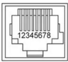
Connector pin-out:
Caution
Check Cat-5 cables for continuity before using them. Using the wrong pin-out may damage the c system and void the warranty.
The Vaddio RoboSHOT Control Protocol is similar to the VISCA command set in order to be compatible with several popular control devices. Not all VISCA commands are supported and there are Vaddio-specific commands in the following command and inquiry lists.
RS-232 Command List
Most of these commands are common to all RoboSHOT series cameras. Some have different value ranges depending on the camera.
| Command Set Command | Command Command | Packet Comments | |
| AddressSet Broadcast | 88 30 01 FF | Sets address for all daisy- | chained cameras |
| IF_Clear Broadcast | 8 01 00 01 FF | I/F Clear | |
| CommandCancel 8x | 2p FF p= Socket No.(1-2) | ||
| CAM_Power | On | 8x 01 04 00 02 FF | Power on |
| Off | 8x 01 04 00 03 FF | Power off | |
| CAM_Zoom | Stop | 8x 01 04 07 00 FF | |
| Tele(std) | 8x 01 04 07 02 FF | ||
| Wide(std) | 8x 01 04 07 03 FF | ||
| Tele(variable) | 8x 01 04 07 2p FF | p= speed 0:low to 7:high | |
| Wide(variable) | 8x 01 04 07 3p FF | p= speed 0:low to 7:high | |
| Direct | 8x 01 04 47 0p 0q 0r 0s | FF pqr=Zoom Position (0h-4000h) | |
| CAM_Focus | Stop | 8x 01 04 08 00 FF | |
| Far (std) 8x 01 | 04 08 02 FF | ||
| Near (std) | 8x 01 04 08 03 FF | ||
| Far (variable) | 8x 01 04 08 2p FF | p= speed 0:low to 7:high | |
| Near (variable) | 8x 01 04 08 3p FF | p= speed 0:low to 7:high | |
| Direct | 8x 01 04 48 0p 0q 0r 0s | FF pqr=Focus Position (1000h - F000h) | |
| Auto Focus | 8x 01 04 38 02 FF | ||
| Manual Focus | 8x 01 04 38 03 FF | ||
| Auto/Manual | 8x 01 04 08 10 FF | ||
| One Push Trigger | 8x 01 04 18 01 FF | One push AF Trigger | |
| Near Limit 8x 01 04 28 0p 0q 0r 0s FF | pqrs=Near focus Limit*** | ||
| CAM_AFSensitivity | Normal | 8x 01 04 58 02 FF | AF Sensitivity High / Low |
| Low | 8x 01 04 58 03 FF | ||
| CAM_AFMode | Normal AF | 8x 01 04 57 00 FF | AF movement mode |
| Internal AF | 8x 01 04 57 01 FF | ||
| Zoom Trigger AF | 8x 01 04 57 02 FF | ||
| Activate/Internal Time | 8x 01 04 27 0p 0q 0r 0s | FF pqr=movement time, rs=Interval | |
| Command Set Command Command and Packet Comments | |||
| CAM_IRCorrection Standard 8x 01 04 11 00 FF Focus IR compensation data switching | |||
| IR light 8x 01 04 11 01 FF | |||
| CAM_ZoomFocus Direct 8x 01 04 47 0p 0q 0r 0s RoboSHOT 12 and RoboSHOT 20 UHD: (0h - 4000h) RoboSHOT 30: (0h - 7AC0h) tuvw=Focus Position (1000h - F000h) | |||
| CAM_WB Auto | 8x 01 04 35 00 FF Normal Auto | ||
| Indoor | 8x 01 04 35 01 FF Indoor mode | ||
| Outdoor | 8x 01 04 35 02 FF Outdoor mode | ||
| One Push WB | 8x 01 04 35 03 FF One Push WB mode | ||
| ATW | 8x 01 04 35 04 FF Auto Tracing White Balance | ||
| Manual | 8x 01 04 35 05 FF Manual Control mode | ||
| One Push Trigger | 8x 01 04 10 05 FF One Push WB Trigger | ||
| Outdoor Auto 8x 01 04 35 06 FF Outdoor auto | |||
| Sodium Lamp Auto | 8x 01 04 35 07 FF Auto including sodium lamp source | ||
| Sodium Lamp | 8x 01 04 35 08 FF Sodium lamp source fixed mode | ||
| Sodium Lamp Outdoor Auto | 8x 01 04 35 09 FF Outdoor auto including sodium lamp source | ||
| CAM_RGain | Reset | 8x 01 04 03 00 FF Manual control of red gain | |
| Up | 8x 01 04 03 02 FF | ||
| Down 8x 01 04 03 03 FF | |||
| Direct | 8x 01 04 43 00 00 0p 0q FF pq=Red gain (00h - FFh) | ||
| CAM_BGain | Reset | 8x 01 04 04 00 FF Manual control of blue gain | |
| Up | 8x 01 04 04 02 FF | ||
| Down 8x 01 04 04 03 FF | |||
| Direct | 8x 01 04 44 00 00 0p 0q FF pq=Blue gain (00h - FFh) | ||
| CAM_AE | Full Auto | 8x 01 04 39 00 FF Auto Exposure mode | |
| Manual | 8x 01 04 39 03 FF Manual Control mode | ||
| Shutter Priority | 8x 01 04 39 0A FF Shutter Priority Auto Exposure mode | ||
| Iris Priority | 8x 01 04 39 0B FF Iris Priority Auto Exposure Mode | ||
| Bright | 8x 01 04 39 0D FF Bright Mode (modified AE mode) | ||
| Command Set | Command Command | Packet Comments | |
| CAM_ExpComp On 8x 01 04 3E 02 | FF Exposure Compensation On | ||
| Off 8x 01 04 3E 03 FF Exposure Compensation Off | |||
| Reset 8x 01 04 0E 00 FF | |||
| Up 8x 01 04 0E 02 FF | |||
| Down 8x 01 04 0E 03 FF | |||
| Direct 8x 01 04 4E 00 00 0p 0q FF pq=ExpComp Position(0h-0Eh) | |||
| CAM_Shutter Reset 8x 01 04 0A 00 | FF Shutter Setting | ||
| Up 8x 01 04 0A 02 FF | |||
| Down 8x 01 04 0A 03FF | |||
| Direct 8x 01 04 4A 00 00 0p 0q FF pq=Shutter Position (00h - 15h)SeeShutter Speed Settings for setting values. | |||
| CAM_Iris | Reset 8x 01 04 0B 00 FF Iris Setting | ||
| Up 8x 01 04 0B 02 FF | |||
| Down 8x 01 04 0B 03 FF | |||
| Direct 8x 01 04 4B 00 00 0p 0q FF pq=Iris PositionRoboSHOT 12: (0h, 07h-11h)RoboSHOT 30 and RoboSHOT 20 UHD: (0h, 05h-11h) | |||
| CAM_Gain | Reset 8x 01 04 0C 00 FF Iris Gain Settingpq=Gain Position (01h - 0Fh) | ||
| Up 8x 01 04 0C 02 FF | |||
| Down 8x 01 04 0C 03 FF | |||
| Direct 8x 01 04 4C 00 00 0p 0q FF | |||
| +Gain Limit | 8x 01 04 2C 0p FF | ||
| CAM_BackLight | On | 8x 01 04 33 02 FF | Backlight Compensation On/Off |
| Off 8x 01 04 33 03 FF | |||
| CAM_Tally | On | 8x 01 7E 01 0A 00 02 FF | |
| Off 8x 01 7E 01 0A 00 03 FF | |||
| Command Set Command Command Packet Comments | |||
| CAM_WD On 8x 01 | 04 3D 02 FF WD On | ||
| Off 8x 01 04 3D 03 FF WD Off | |||
| VE On 8x 01 04 3D 06 FF VE On | |||
| Set Parameter | 8x 01 04 2D 00 0q 0r 0s00 00 00 00 FF | q=Display brightness (0 Dark - 6 Bright)r=Brightness compensation(0: Very dark, 1: Dark, 2: std, 3: bright)s=Compensation level (0: Low, 1: Mid, 2: High) | |
| CAM_Aperture Reset | 8x 01 04 02 00 FF Aperture Setting | ||
| Up 8x 01 04 02 01 FF | |||
| Down | 8x 01 04 02 02 FF | ||
| Direct 8x 01 04 42 00 00 0p 0q FF pq=Aperture Position (0h-0fh) | |||
| CAM_HR | On 8x 01 04 52 02 FF High R | Resolution Mode On/Off | |
| Off 8x 01 04 52 03 FF | |||
| CAM_NR | -- | 8x 01 04 53 0p FF | p= Noise Reduction level(0:Off, 1-5) |
| CAM_Gamma | -- | 8x 01 04 5B 0p FF | p= Gamma setting (0:std, 1:Straight) |
| CAM_LR_Reverse | On | 8x 01 04 61 02 FF | LR Reverse On/Off (mirror) |
| Off 8x 01 04 61 03 FF | |||
| CAM_Freeze | On | 8x 01 04 62 02 FF | Freeze On/Off |
| Off 8x 01 04 62 03 FF | |||
| CAM_PictureEffect | Off | 8x 01 04 63 00 FF | Picture Effect Setting |
| Neg.Art | 8x 01 04 63 02 FF | ||
| Black & White | 8x 01 04 63 04 FF | ||
| CAM_PictureFlip | On | 8x 01 04 66 02 FF | Image-Flip On/Off |
| Off 8x 01 04 66 03 FF | |||
| CAM_ICR | On | 8x 01 04 01 02 FF | ICR Mode On/Off - adds an IR cut filter to the image for low light images |
| Off 8x 01 04 01 03 FF | |||
| CAM_IDWrite | 8x 01 04 22 0p 0q 0r 0s FF | pqrs=Camera ID (0h-ffffh) | |
| Cam_Display | On | 8x 01 04 15 02 FF | Display On/Off |
| Off 8x 01 04 15 03 FF | |||
| On/Off 8x 01 04 15 10 FF | |||
| Command Set | Command Command | Packet Comments | |
| Cam_Mute On 8x 01 | 04 75 02 FF | Mute On/Off | |
| Off 8x 01 04 7 | 5 03 FF | ||
| On/Off 8x 01 04 75 10 FF | |||
| CAM_ColorEnhance | Parameter Set 8x 01 04 20 mm 00 pp qq rr ss tt uu FF | mm: Threshold levelpp: Y fixed color for high-intensityqq: Cr fixed color for high-intensityrr: Cb fixed color for high-intensityss: Y fixed color for low-intensitytt: Cr fixed color for low-intensityuu: Cb fixed color for low-intensityEach parameter setting 00h to 7Fh | |
| On 8x 01 04 50 02 FF Color Enhancement On/Off | |||
| Off 8x 01 04 50 03 FF | |||
| CAM_ChromaSuppress | 8x 01 04 5F pp FF pp: Chroma Suppress level00: Off01h to 03h: On (3 levels; larger number = larger effect) | ||
| CAM_ColorGain | Direct | 8x 01 04 49 00 00 00 0p FF | p: Color Gain Setting 0h to 4h |
| CAM_ColorHue | Direct | 8x 01 04 4F 00 00 00 0p FF | p: Color Hue Setting 0h (-14 degrees) to Eh (+14 degrees) |
| CAM_GammaOffset | Direct | 8x 01 04 1E 00 00 00 0u FF | s: Polarity offset (0 is plus, 1 is minus)tu:RoboSHOT 12 - Offset s=0 (00h to 10h)RoboSHOT 30 - Offset s=1 (00h to 40h) |
| Pan-TiltDrive Up 8x | 01 06 01 vv ww | 03 01 FF vv= Pan speed | (01h-18h)ww=Tilt speed (01h-14h) |
| Down 8x 01 06 | 01 vv ww 03 02 FF | ||
| Left 8x 01 06 | 01 vv ww 01 03 FF | ||
| Right 8x 01 06 | 01 vv ww 02 03 FF | ||
| UpLeft 8x 01 06 | 01 vv ww 01 01 FF | ||
| UpRight 8x 01 | 06 01 vv ww 02 01 FF | ||
| DownLeft | 8x 01 06 01 vv ww 01 02 FF | ||
| DownRight | 8x 01 06 01 vv ww 02 02 FF | ||
| Stop | 8x 01 06 01 vv ww 03 03 FF | ||
| Absolute Position | 8x 01 06 02 vv ww 0Y 0Y0Y0Y0Y0Y = Pan position(90E2h-6BD8h)0Z0Z0Z0Z = Tilt position(EB99h-3D59h) | ||
| 0Y0Z 0Z 0Z 0Z FF | |||
| Home | 8x 01 06 04 FF | Returns the camera to its default position | |
| Pan-Tilt-ZoomDrive | Up | 8x 01 06 0A vv ww rr 03 01 03 FF | vv= Pan speed (01h-18h)ww=Tilt speed (01h-14h)rr=Zoom speed (00h-07h) |
| Down 8x 01 06 | 0A vv ww rr 03 02 03 FF | ||
| Left 8x 01 06 | 0A vv ww rr 01 03 03 FF | ||
| Right 8x 01 06 | 0A vv ww rr 02 03 03 FF | ||
| In | 8x 01 06 0A vv ww rr 03 01 FF | 03 | |
| Out 8x 01 06 | 0A vv ww rr 03 0302 FF | ||
| Stop 8x 01 06 | 0A vv ww rr 03 0303 FF | ||
| Absolute Position | 8x 01 06 0B vv ww 0Y0Y 0Y0Z 0Z 0Z 0Z 0R 0R 0R FF | 0Y0Y0Y0Y = Pan position(90E2h-6BD8h)0Z0Z0Z0Z = Tilt position(EB99h-3D59h)0R0R0R0R = Zoom positionRoboSHOT 12: 0000h-4000hRoboSHOT 30 and RoboSHOT20 UHD: 0000h-7AC0h | |
| Home 8x 01 06 | 0C FF Returns the camera | era to the defaultposition and zoom | |
| CAM_PTZ_PresetSpeed | 8x 01 7e 01 0b pp qq rr | FF pp:pan speed (01h-18h),qq:tilt speed (01h-14h),rr:zoom speed (0h-07h)Applies only if Tri-SynchronousMotion is not used. | |
Command Setting Values
Valid settings for these commands:
■ CAM_ExpComp
■ CAM_Shutter
■ CAM Iris
■ CAM_Gain
Exposure Compensation
Command: CAM_ExpComp
| Value Iris | Gain | |
| 0x0E +7 +10.5 | dB | |
| 0x0D +6 +9 dB | ||
| 0x0C +5 +7.5 | dB | |
| 0x0B +4 +6 dB | ||
| 0x0A +3 +4.5 | dB | |
| 0x09 +2 +3 dB | ||
| 0x08 +1 +1.5 | dB | |
| 0x07 0 0 dB | ||
| 0x06 -1 -1.5 dB | ||
| 0x05 -2 -3 dB | ||
| 0x04 -3 -4.5 dB | ||
| 0x03 -4 -6 dB | ||
| 0x02 -5 -7.5 dB | ||
| 0x01 -6 -9 dB | ||
| 0x00 -7 -10.5 | dB |
Shutter Speed Values
Command: CAM_Shutter
| Value 60/59.94/30/29.97 50/25 | ||||
| 0x15 | 1/10 | 000 | 1/10000 | |
| 0x14 | 1/60 | 00 | 1/6000 | |
| 0x13 | 1/40 | 00 | 1/3500 | |
| 0x12 | 1/30 | 00 | 1/2500 | |
| 0x11 | 1/20 | 00 | 1/1750 | |
| 0x10 | 1/15 | 00 | 1/1250 | |
| 0x0F | 1/10 | 00 | 1/1000 | |
| 0x0E | 1/725 | 1/600 | ||
| 0x0D | 1/500 | 1/425 | ||
| 0x0C | 1/350 | 1/300 | ||
| 0x0B | 1/250 | 1/215 | ||
| 0x0A | 1/180 | 1/150 | ||
| 0x09 | 1/125 | 1/120 | ||
| 0x08 | 1/100 | 1/100 | ||
| 0x07 | 1/90 | 1/75 | ||
| 0x06 | 1/60 | 1/50 | ||
| 0x05 | 1/30 | 1/25 | ||
| 0x04 | 1/15 | 1/12 | ||
| 0x03 | 1/8 | 1/6 | ||
| 0x02 | 1/4 | 1/3 | ||
| 0x01 | 1/2 | 1/2 | ||
| 0x00 | 1/1 | 1/1 | ||
Iris Position Values
Command: CAM_Iris
| Value | RoboSHOT 20 UHD |
| 0x11 | F1.8 |
| 0x10 | F2 |
| 0x0F | F2.4 |
| 0x0E | F2.8 |
| 0x0D | F3.4 |
| 0x0C | F4 |
| 0x0B | F4.8 |
| 0x0A | F5.6 |
| 0x09 | F6.8 |
| 0x08 | F8 |
| 0x07 | F9.6 |
| 0x06 | F11 |
| 0x05 | F14 |
| 0x00 | CLOSE |
Iris Gain Values
Command: CAM_Gain
| Value Gain | |
| 0x10 45 dB | |
| 0x0F 42 dB | |
| 0x0E 39 dB | |
| 0x0D 36 dB | |
| 0x0C 33 dB | |
| 0x0B 30 dB | |
| 0x0A 27 dB | |
| 0x09 24 dB | |
| 0x08 21 dB | |
| 0x07 18 dB | |
| 0x06 15 dB | |
| 0x05 12 dB | |
| 0x04 9 dB | |
| 0x03 6 dB | |
| 0x02 3 dB | |
| 0x01 0 dB | |
Note
Values 0D to 10 can be set only when the high-sensitivity mode is ON. By default, it is off up/reboot.
Iris Gain Limit Values
Command: CAM_Gain
| Value | High Sensitivity Off High Sensitivity On | |
| 0x0C | 33 dB 45 dB | |
| 0x0B | 30 dB 42 dB | |
| 0x0A | 27 dB 39 dB | |
| 0x09 | 24 dB 36 dB | |
| 0x08 | 21 dB 33 dB | |
| 0x07 | 18 dB 30 dB | |
| 0x06 | 15 dB 27 dB | |
| 0x05 | 12 dB 24 dB | |
| 0x04 | 9 dB | 21 dB |
RS-232 Inquiry Command List
| Inquiry Command | Command Response | Packet Comments | |
| CAM_PowerInq 8x 09 04 00 FF y0 50 | 02 FF On | ||
| y0 50 03 FF Off (Standby) | |||
| CAM_ZoomPosInq 8x 09 04 47 FF y0 | 50 0p 0q 0r 0s FF pqs: Zoom Position | ||
| CAM_FocusModelInq | 8x 09 04 38 FF | y0 50 02 FF Auto Focus | |
| y0 50 03 FF Manual Focus | |||
| CAM_FocusPosInq | 8x 09 04 48 FF | y0 50 0p 0q 0r 0s FF | pqrs: Focus Position |
| CAM_FocusNearLimitInq | 8x 09 04 28 FF | y0 50 0p 0q 0r 0s FF | pqrs: Focus Near Limit Position |
| CAM_AFSensitivityInq | 8x 09 04 58 FF | y0 50 02 FF AF Sensitivity Normal | |
| y0 50 03 FF AF Sensitivity Low | |||
| CAM_AFModeInq | 8x 09 04 57 FF | y0 50 00 FF Normal AF | |
| y0 50 01 FF Interval AF | |||
| y0 50 02 FF Zoom Trigger AF | |||
| CAM_AFTimeSettingInq | 8x 09 04 27 FF | y0 50 0p 0q 0r 0s FF | pq: Movement Time, rs: Interval |
| CAM_IRCorrectionInq | 8x 09 04 11 FF | y0 50 00 FF Standard | |
| y0 50 01 FF IR Light | |||
| CAM_WBModelInq | 8x 09 04 35 FF | y0 50 00 FF Auto | |
| y0 50 01 FF Indoor | |||
| y0 50 02 FF Outdoor | |||
| y0 50 03 FF One Push WB | |||
| y0 50 04 FF ATW | |||
| y0 50 05 FF Manual | |||
| y0 50 06 FF Outdoor Auto | |||
| y0 50 07 FF Sodium Lamp Auto | |||
| y0 50 08 FF Sodium Lamp | |||
| y0 50 09 FF Sodium Lamp Outdoor Auto | |||
| CAM_RGainInq | 8x 09 04 43 FF | y0 50 00 00 0p 0q FF | pq: R Gain |
| CAM_BGainInq | 8x 09 04 44 FF | y0 50 00 00 0p 0q FF | pq: B Gain |
| CAM_AEModelInq | 8x 09 04 39 FF | y0 50 00 FF Full Auto | |
| y0 50 03 FF Manual | |||
| y0 50 0A FF | Shutter Priority | ||
| y0 50 0B FF | Iris Priority | ||
| y0 50 0D FF | Bright | ||
| CAM_ShutterPoslnq | 8x 09 04 4A FF | y0 50 00 00 0p 0q FF | pq: Shutter Position |
| CAM_IrisPoslnq 8x | 09 04 4B FF y0 | 50 00 00 0p 0q FF pq: | Iris Position |
| CAM_GainPoslnq 8x | 09 04 4C FF y0 | 50 00 00 0p 0q FF pq: | Gain Position |
| CAM_GainLimitlnq 8x | 09 04 2C FF y0 | 50 0q FF p: Gain Limit | |
| CAM_ExpCompModelnq | 8x 09 04 3E FF | y0 50 02 FF On | |
| y0 50 03 FF Off | |||
| CAM_ExpCompPoslnq | 8x 09 04 4E FF | y0 50 00 00 0p 0q FF | pq: ExpComp Position |
| CAM_BackLightModelnq | 8x 09 04 33 FF | y0 50 02 FF On | |
| y0 50 03 FF Off | |||
| CAM_Tallylnq | 8x 09 7E 01 0A | FF y0 50 02 FF On | |
| y0 50 03 FF Off | |||
| CAM_SpotAEModelnq | 8x 09 04 59 FF | y0 50 02 FF On | |
| y0 50 03 FF Off | |||
| CAM_SpotAEPoslnq | 8x 09 04 29 FF | y0 50 0p 0q 0r 0s FF | pq: X Position, rs: Y Position |
| CAM_WDModelnq 8x | 09 04 3D FF y0 | 50 02 FF On | |
| y0 50 03 FF Off | |||
| y0 50 06 FF VE On | |||
| CAM_WDParameterlnq | 8x 09 04 2D FF | y0 50 00 0q 0r 0s 0t 00 FF | q: Display brightness level (0: Dark to 6: Bright)r: Brightness compensation selection (0: Very dark,1: Dark, 2: Standard, 3: Bright)s: Compensation level (00h: Low: Mid, 02h: High)tu: Always 0 |
| CAM_Aperturelnq | 8x 09 04 42 FF | y0 50 00 00 0p 0q FF | pq: Aperture Gain |
| CAM_HRModelnq | 8x 09 04 52 FF | y0 50 02 FF On | |
| y0 50 03 FF Off | |||
| CAM_NRInq | 8x 09 04 53 FF | y0 50 0p FF Noise | Reduction p: 00h to 05h |
| CAM_Gammalnq | 8x 09 04 5B FF | y0 50 0p FF Gamma | p: 00h , 01h |
| CAM_LR_ReverseModelnq | 8x 09 04 61 FF | y0 50 02 FF On (mirror) | |
| y0 50 03 FF Off | |||
| CAM_FreezeModelnq | 8x 09 04 62 FF | y0 50 02 FF On | |
| y0 50 03 FF Off | |||
| CAM_PictureEffectModelnq | 8x 09 04 63 FF | y0 50 00 FF Off | |
| y0 50 02 FF Neg. Art | |||
| y0 50 04 FF Black & White | |||
| CAM_PictureFlipModelnq | 8x 09 04 66 FF | y0 50 02 FF On | |
| y0 50 03 FF Off | |||
| CAM_ICRModelnq 8x | 09 04 01 FF y0 | 50 02 FF On | |
| y0 50 03 FF Off | |||
| CAM_MemoryInq 8x | 09 04 3F FF y0 | 50 pp FF pp: Memory | number recalled last |
| CAM_MemoryStatusInq | 8x 09 04 3F 0p | FF y0 50 0p 0q 0r 0s | FF p: Memory numberq: mode (00-std, 10-std /w ccu, 01-trisync,11-trisyc /w ccu)rs: speed (0x1-0x18) 1 - 24 |
| CAM_MemSaveInq | 8x 09 04 23 0X FF | y0 50 0p 0q 0r 0s FF | X: 00h to 07h (Address)pqrs: 0000h to FFFFh (Data) |
| CAM_DisplayModelnq | 8x 09 04 15 FF(8x 09 06 06 FF) | y0 50 02 FF On | |
| y0 50 03 FF Off | |||
| CAM_MuteModelnq | 8x 09 04 75 FF | y0 50 02 FF On | |
| y0 50 03 FF Off | |||
| CAM_IDInq | 8x 09 04 22 FF | y0 50 0p 0q 0r 0s FF | pqrs: Camera ID |
| CAM_VersionInq | 8x 09 00 02 FF | y0 50 00 10mn pq 0E 0E 02 FF | mnpq: Model Code |
| Vaddio_ModelInq | 8x 09 08 0e FF | y0 50 05 00 00 00 00 | FF RoboSHOT 12 |
| y0 50 05 01 00 00 00 | FF RoboSHOT 30 | ||
| y0 50 05 02 00 00 00 | FF RoboSHOT 12 USB | ||
| y0 50 05 04 00 00 00 | FF RoboSHOT 12 HDMI | ||
| y0 50 05 05 00 00 00 | FF RoboSHOT 30 HDMI | ||
| y0 50 05 06 00 00 00 | FF RoboSHOT 12 HD-SDI | ||
| y0 50 05 07 00 00 00 | FF RoboSHOT 30 HD-SDI | ||
| y0 50 06 01 00 00 00 | FF RoboSHOT 20 UHD | ||
| CAM_RegisterValueInq | 8x 09 04 24 mmFF | y0 50 0p 0p FF | mm: Register No. (=00h to 7Fh)pp: Register Value (=00h to FFh) |
| CAM_ColorEnhancelnq | 8x 09 04 20 FF | y0 50 mm 00 pp qq ruu FF | mn:ttThreshold levelpp: Y fixed color for high-intensityqq: Cr fixed color for high-intensityrr: Cb fixed color for high-intensityss: Y fixed color for low-intensitytt: Cr fixed color for low-intensityuu: Cb fixed color for low-intensity |
| 8x 09 04 50 FF | y0 50 02 FF On | ||
| y0 50 03 FF Off | |||
| CAM_ChromaSuppressInq | 8x 09 04 5F FF | y0 50 pp FF pp: Chroma Suppress setting level | |
| CAM_ColorGainInq | 8x 09 04 49 FF y0 | 50 00 00 00 0p FF p: Color Gain Setting 0h to 4h | |
| CAM_ColorHuelnq | 8x 09 04 4F FF y0 | 50 00 00 00 0p FF p: Color Hue Setting 0h (-14 degrees) to Eh (+14 degrees) | |
| CAM_TemplInq | 8x 09 04 68 FF Y0 50 | 00 00 0p 0q FF | pq: Lens Temperature |
| CAM_GammaOffsetInq | 8x 09 04 1E FF | y0 50 00 00 00 0s FF | t Polarity offset (0 is plus, 1 is minus)tu: Offset s=0 (00h to 40h)Offset s=1 (00h to 10h) |
| Pan-tiltPosInq | 8x 09 06 12 FF | y0 50 0w 0w 0w 0w 0z 0z 0z 0z FF | www= Pan positionzzzz=Tilt Position |
Specifications
Camera and image
| Image device | RoboSHOT 12 HDBT: 1/2.8-Type Exmo CMOS sensorRoboSHOT 30 HDBT: 1/2.8-Type Exmor RTM backlit CMOS sensor | ||
| Pixels | 2.14 million (effective), 2.38 million (total) | ||
| Pan and tilt | Pan ± 160°, tilt +90° -30°; pan and tilt speed 0.35°/sec to 120°/sec | ||
| Lens and horizontal | FGVboSHOT 12 HDBTNormal (default): 10X optical zoom, 67.3° (wide) to 7.6° (tele), f=3.8mm to 38.0mm, F1.8 to F3.4Super Wide: 12X optical zoom, 73.0° (wide) to 6.6° (tele), f=3.91mm to 47.0mm, F3.4RoboSHOT 30 HDBT30X optical zoom, 65° (wide) to 2.3° (tele), F1.6 to F4.7 | ||
| Min. working distance | RoboSHOT 12 HDBT: 10mm (wide), 0.8m (tele)RoboSHOT 30 HDBT: 10mm (wide), 1.2m (tele) | ||
| Min. illumination | Recommended: 100+ lux | Gain | Auto / Manual (28 steps) |
| Backlight compensation | On/off | Aperture/detail | 16 steps |
| Focusing system | Auto Focus / Manual Focus Mode / One Push Trigger Mode / Infinity Mode / Near Limit Mode | ||
| White balance | Auto, ATW, Indoor, Outdoor, One-push, Manual | ||
| Sync system | Internal | S/N ratio | More than 50 dB |
| Noise reduction | On/Off, 6 Steps | Power | 12 VDC, 3.0 A or PoE+ |
| Remote management | IR Remote Commander, web interface, Telnet and RS-232 command APIs | ||
Physical and Environmental
| Height | 6.9 in. (176 mm) | Weight | 4.85 lbs.(2.2 kg) |
| Width | 7.1 in. (179 mm) | Operating/storage temperature | 0°C to +40°C (32°F to 104°F) |
| Depth | 6.8 in. (172 mm) | Operating/storage humidity | 20% to 80% RH, non-condensing |
Specifications are subject to change without notice.
Troubleshooting and Care
When the camera doesn't behave as you expect, check the color of the indicator light on the front before you do anything else.
■ Blue: Normal operation (blinks off momentarily when the camera receives a command from the remote)
■ Purple: In standby mode or booting
■ Yellow: Firmware update in progress
■ Flashing purple: Error
■ Red: On-air tally
Stuff happens – we get it. Use this table to determine whether it's time to call Vaddio Technical Support.
| What is it doing? Possible causes Check and correct | ||
Nothing.The light on the front is off. | If a OneLINK extension module is used: The camera not connected to the OneLINK module. | Plug the OneLINK module into the camera.Plug the OneLINK module's power supply into a wall outlet. |
| If a OneLINK extension module is used: The OneLINK power supply is not connected. | Test by connecting the camera directly K the 12VDC power pack that was shipped with it.CautionDo not connect the camera to the 48 VDC OneLINK power pack. This will damage the camera and void its warranty.If the camera works when it is connected to its 12 VDC power supply, but not when connected to the the OneLINK module, the OneLINK is bad.Contact your reseller or Vaddio Technical Support. | |
| If a OneLINK extension module is used: The OneLINK module is not working properly. | ||
| Insufficient power using a PoE+ power injector – PoE does injector. | ||
| At least one of the cables is bad. | ||
| The camera or its power sur Iqptact your reseller or Vaddio is bad. | ||
| The wall outlet is not active. Use a different outlet.(Check by finding out if it powers something else, such as a laptop or phone charger.) | ||
| The camera never finishes initializing and the light is put in an initial power source. | Insufficient power using a PoE+ power injector instead. Inverter. | |
| The camera is not responding the remote and the light is yellow. | At firmware update is in progress. | Wait a few minutes, and try again when the light turns blue. |
| The camera does not respond the remote, but the web interface is available | The remote is not using the same IR channel as the camera. | Push the Camera Select 1 button on the remote. Try the other Camera Select buttons if necessary. |
| IR is switched off (DIP switch 3 down) | Turn IR on (DIP switch 3 up) - see Camera Settings for more information. | |
| The batteries in the remote dead. | Not new batteries in the remote. | |
| The camera responds to the remote but the web interface not available. | The camera is not using the address you browsed to. | Press the Data Screen button on the remote to see camera information. |
| The web interface has stopped responding. | Reboot the camera. | |
| The camera's web UI is available but the camera does not respond to commands via RS-232 connection. | The RS-232 cable is not connected, or is bad. | Connect a known good cable. |
| The camera's RS-232 setting don't match the settings on controlling device. | Check the settings at both ends to be there they match. The camera's current settings can be viewed on the System page in the web UI.Correct the settings where it's more convenient to do so. | |
| The camera loses all its sett when power is cycled. | Ads the DIP switches are in ON (down) position. | Set the DIP switches to their proper positions. Default is all OFF (up). See Switch Settings for more information. |
| No H.264 video stream. Streaming is not enabled. Enable streaming: Streaming page in the web interface. | ||
Operation, Storage, and Care
For smears or smudges on the product, wipe with a clean, soft cloth. Use a lens cleaner on the lens. Do not use any abrasive chemicals.
Keep this device away from food and liquids.
Do not operate or store the device under any of the following conditions:
■ Temperatures above 40^ C ( 104^ F) or below 0^ C ( 32^ F)
■ High humidity, condensing or wet environments
■ Inclement weather
■ Severe vibration
■ Between converging tectonic plates
■ Dry environments with an excess of static discharge
Do not attempt to take this product apart. There are no user-serviceable components inside.
Compliance Statements and Declarations of Conformity
Compliance testing was performed to the following regulations:
FCC Part 15 (15.107, 15.109), Subpart B Class A
ICES-003, Issue 54: 2012 Class A
EMC Directive 2004/108/EC Class A
EN 55022: December 2010 Class A
EN 55024: November 2010 Class A
KN22 2008 (CISPR 22: 2006) Class A
KN24 2008 (CISPR 24: 1997 + A1: 2000 + A2: 2002) Class A
IEC 60950-1:2005 (2nd Edition); Am 1: 2009 + Am 2: 2013 Safety
EN 60950-1: 2006 + A11: 2009 + A1: 2010 + A12: 2011 + A2: 2013 Safety
FCC Part 15 Compliance
This equipment has been tested and found to comply with the limits for a Class A digital device, pursuant to Part 15, Subpart B, of the FCC Rules. These limits are designed to provide reasonable protection against harmful interference when the equipment is operated in a commercial environment. This equipment generates, uses, and can radiate radio frequency energy and, if not installed and used in accordance with the instruction manual, may cause harmful interference to radio communications. Operation of this equipment in a residential area is likely to cause harmful interference in which case the user will be required to correct the interference at his/her own expense.
Operation is subject to the following two conditions: (1) This device may not cause interference, and (2) This device must accept any interference including interference may cause undesired operation of the device.

Changes or modifications not expressly approved by Vaddio can affect emission compliance and could void the user's authority to operate this equipment.
ICES-003 Compliance
This digital apparatus does not exceed the Class A limits for radio noise emissions from digital apparatus set out in the Radio Interference Regulations of the Canadian Department of Communications.
This product has been evaluated for electromagnetic compatibility under the EMC Directive for Emissions and Immunity and meets the requirements for a Class A digital device. In a domestic environment this product may cause radio interference in which case the user may be required to take adequate measures.
Standard(s) To Which Conformity Is Declared:

EMC Directive 2004/108/EC
EN 55022: December 2010 Conducted and Radiated Emissions
EN 55024: November 2010 Immunity
EN 61000-4-2: 1995 + Amendments A1: 1998 + A2: 2001 Electrostatic Discharge
EN 61000-4-3: 2006 + A1: 2008 Radiated Immunity
EN 61000-4-4: 2004 + Corrigendum 2006 Electrical Fast Transients
EN 61000-4-5: 2006 Surge Immunity
EN 61000-4-6: 2009 Conducted Immunity
EN 61000-4-8: 2010 Power Frequency Magnetic Field
EN 61000-4-11: 2004
Voltage Dips, Interrupts and
Fluctuations
KN22 2008 (CISPR 22: 2006) Conducted and Radiated Emissions
KN24 2008 (CISPR 24: 1997 + A1: 2000 + A2: 2002) IT Immunity Characteristics
EN 61000-4-2 Electrostatic Discharge
EN 61000-4-3 Radiated Immunity
EN 61000-4-4 Electrical Fast Transients
EN 61000-4-5 Surge Immunity
EN 61000-4-6 Conducted Immunity
EN 61000-4-8 Power Frequency Magnetic Field
EN 61000-4-11
Voltage Dips, Interrupts and
Fluctuations
IEC 60950-1: 2005 (2nd Edition); Am 1: 2009 + Am 2: 2013
Safety
EN 60950-1: 2006 + A11: 2009 + A1: 2010 + A12: 2011 + A2:
Safety
2013
Warranty Information
See Vaddio Warranty, Service and Return Policies posted on support.vaddio.com for complete details.
Hardware* warranty: Two (2) year limited warranty on all parts and labor for Vaddio manufactured products. Vaddio warrants its manufactured products against defects in materials and workmanship for a period of two years from the day of purchase, to the original purchaser, if Vaddio receives notice of such defects during the warranty. Vaddio, at its option, will repair or replace products that prove to be defective. Vaddio manufactures its hardware products from parts and components that are new or equivalent to new in accordance with industry standard practices.
Exclusions: The above warranty shall not apply to defects resulting from improper or inadequate maintenance by the customer, customers applied software or interfacing, unauthorized modifications or misuse, mishandling, operation outside the normal environmental specifications for the product, use of the incorrect power supply, modified power supply or improper site operation and maintenance. OEM and special order products manufactured by other companies are excluded and are covered by the manufacturer's warranty.
Vaddio Customer Service: Vaddio will test, repair, or replace the product or products without charge if the unit is under warranty. If the product is out of warranty, Vaddio will test then repair the product or products. The cost of parts and labor charge will be estimated by a technician and confirmed by the customer prior to repair. All components must be returned for testing as a complete unit. Vaddio will not accept responsibility for shipment after it has left the premises.
Vaddio Technical Support: Vaddio technicians will determine and discuss with the customer the criteria for repair costs and/or replacement. Vaddio Technical Support can be contacted by email at support@vaddio.com or by phone at one of the phone numbers listed on support.vaddio.com.
Return Material Authorization (RMA) number: Before returning a product for repair or replacement request an RMA from Vaddio's technical support. Provide the technician with a return phone number, e-mail address, shipping address, product serial numbers and original purchase order number. Describe the reason for repairs or returns as well as the date of purchase. See the General RMA Terms and Procedures section for more information. RMAs are valid for 30 days and will be issued to Vaddio dealers only. End users must return products through Vaddio dealers. Include the assigned RMA number in all correspondence with Vaddio. Write the assigned RMA number clearly on the shipping label of the box when returning the product. All products returned for credit are subject to a restocking charge without exception. Special order product are not returnable.
Voided warranty: The warranty does not apply if the original serial number has been removed or if the product has been disassembled or damaged through misuse, accident, modifications, use of incorrect power supply, use of a modified power supply or unauthorized repair.
Shipping and handling: Vaddio will not pay for inbound shipping transportation or insurance charges or accept any responsibility for laws and ordinances from inbound transit. Vaddio will pay for outbound shipping, transportation, and insurance charges for all items under warranty but will not assume responsibility for loss and/or damage by the outbound freight carrier. If the return shipment appears damaged, retain the original boxes and packing material for inspection by the carrier. Contact your carrier immediately.
Products not under warranty: Payment arrangements are required before outbound shipment for all out of warranty products.
Index
A
admin login 16-17, 29
changing 29
default 16
anatomy of the camera 5
API 42, 54
syntax help 54
auto focus 22, 45
auto iris 36, 47-48
auto white balance 36, 47-48
automatic NTP updating 31
B
backing up a configuration 37
backlight compensation 36, 47-48
baud rate setting 7
behavior on power-up 13, 28
blue gain 36, 47-48
browser compatibility 16
C
cable connectors 9
Camera Control page (web) 20
camera ID setting (DIP switch) 7
camera mount, installing 10
camera power 11
camera select 14-15See also camera ID setting (DIP switch)
Camera Settings page (web) 35
camera specifications 71
camera standby position 21
CCU scenes 24, 28, 36, 49
custom 24, 36, 49
recalling 49
CCU settings 46-48
ceiling-mounted cameras 10
cheat sheet 14, 19
Vaddio IR Remote Commander 14
web interface 19
chroma setting 36, 47-48
cleaning 73
color settings 24, 36, 47-48
color space setting 7
colors of the status light 5, 72
command history 53
compatibility, browsers 16
configuration, saving or restoring 37
connection example 11
connector identification 6
connector pin-out, RS-232 55
custom CCU scenes 36
custom home position, setting 28
D
damage, preventing 8-9, 55
default IP address 16
default settings, restoring 38, 52
detail setting 36, 47-48
DHCP 30
diagnostic logs 41
Diagnostics page (web) 41
DIP switch settings 7, 39
reading from web interface 39
directional controls 14-15, 21
F
factory defaults, restoring 38, 52
fault isolation 72
firmware update 37-38
firmware version 37, 53
focus 14-15, 22, 45
G
gain 36, 47
blue 36
red 36
getting help 40
guest access 17, 29
allowing 29
H
Help page (web) 40
home position 21, 28, 43
custom 28
hostname 30
|
image flip setting (DIP switch) 7
importing a configuration 37
inactive sessions (web interface) 29
indicator light 72
information, conference room 29
installation, typical 11
inverted installation 10
IP address 14-16, 30
default 16, 30
IP streaming 32-34, 50
enabling or disabling 32
resolutions and frame rates 32 settings 33-34, 50
IR on/off (DIP switch) 7
IR remote 14-15
iris settings 36, 47-48
L
labels, room 29
lighting settings 24, 36, 47-49
locations of connectors 6
log files 41
login 16-17
admin 16-17
user 16
low-power state 21, 49
M
manual focus 14-15, 22, 45
mounting cameras 8, 10, 12
N
network configuration 16, 30, 50
default 16, 30
Networking page (web) 30
NTP server 31
O
OneLINK 11, 72
OneLINK system 11
operating environment 73
P
packing lists 2
page 20, 29-30, 32, 35, 37, 40-41
Camera Control 20
Camera Settings 35
Diagnostics 41
Help 40
Networking 30
Room Labels 29
Security 29
Streaming 32
System 37
pan 27, 43
direction 27
pan/tilt/zoom 14-15, 36
pan/tilt/zoom controls 21
passwords 29
performance specifications 71
physical and environmental specifications 71
pin-out, RS-232 connector 55
ping command 51
PoE+ power 11
power-up settings 28
power on/power off 13-15
power options 11
presets 14-15, 23, 25, 46
clearing 15
moving to 23, 46
setting 15, 25, 46
product returns and repairs 76
Q
quick reference 14, 19
Vaddio IR Remote Commander 14
web interface 19
R
ready state 21, 49
rebooting the camera 37, 51
red gain 36, 47-48
remote control 14-15
resolution 6, 32
IP streaming 32
switch setting 6
restoring a configuration 37
restoring default settings 38, 52
RJ-45 connectors 9
room information 29
Room Labels page (web) 29
RS-232 commands 56, 67
RS-232 serial connection 55
S
saving a configuration 37
scenes, CCU 24, 36
naming 36
storing 36
Scott 24
Security page (web) 29
session time-out 29
settings, default, restoring 38, 52
shelf-mounted cameras 12
shelf, camera mount 10
soft DIP switches 39
solving problems 72
specifications 71
speed 26, 35-36, 43-45
focus 45
pan/tilt/zoom 26, 36, 43-44
standby state 21, 49
start-up behavior, setting 28
static IP address 30
status light, meanings of colors 5, 72
storage environment 73
storing a configuration 37
Streaming page (web) 32
streaming settings 32, 50
super-wide mode setting (DIP switch) 7
supported web browsers 16
switch settings 7, 10, 37
baud rate (DIP switch) 7
camera ID (DIP switch) 7
color space (DIP switch) 7
image flip (DIP switch) 7, 10
IR 7
reading from web interface 37
super wide mode (DIP switch) 7
switch, video resolution 6
System page (web) 37
system time 31
T
technical specifications 71
technical support 40
Telnet command help 54
Telnet session 42, 53-54
ending 54
history 53
temperature, operating and storage 73
tilt 27, 44
direction 27
time zone 31
typical installation 12
U
update 38
user login 16, 29
changing 29
default 16
V
Vaddio IR Remote Commander 14-15
version, firmware 53
video resolution setting 6
W
wall-mounted cameras 12
wall mount 10
warranty 8, 76
web browsers supported 16
web interface 20, 29-30, 32, 35, 37, 40-41
Camera Control page 20
Camera Settings page 35
Diagnostics page 41
Help page 40
Networking page 30
Room Labels page 29
Security page 29
Streaming page 32
System page 37
wide dynamic range setting 36, 47-48
Z
zoom 21, 44
zoom speed 14-15, 26, 44
Vaddio is a brand of Milestone AV Technologies · www.vaddio.com · Phone 800.572.2011 /
+1.763.971.4400 · Fax +1.763.971.4464 · Email info@vaddio.com
Visit us at support.vaddio.com for firmware updates, specifications, drawings, manuals, technical support information, and more. Vaddio, RoboSHOT, and OneLINK are trademarks or registered trademarks of Milestone AV Technologies. HDBaseT™ and the HDBaseT Alliance logo are trademarks of the HDBaseT Alliance. Exmor® is a trademark of Sony Corporation. All other brand names or marks are used for identification purposes and are trademarks of their respective owners. In British Columbia, Milestone AV Technologies ULC carries on business as MAVT Milestone AV Technologies ULC.
©2017 Milestone AV Technologies
vaddio
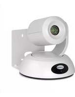
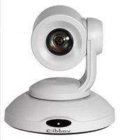
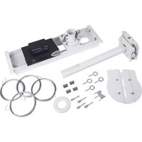
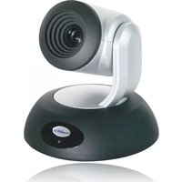
- RoboSHOT 12 HDBT and
- RoboSHOT 30 HDBT
- Contents
- Overview
- What's in this Guide
- Camera Features
- Unpacking the Camera
- Caution
- RoboSHOT 12 HDBT, North America - 999-9960-000
- RoboSHOT 12 HDBT, Europe and UK - 999-9960-001
- RoboSHOT 12 HDBT, Australia and New Zealand - 999-9960-009
- RoboSHOT 30 HDBT, North America, black - 999-9963-000
- RoboSHOT 30 HDBT, North America, white - 999-9963-000W
- A Quick Look at the Camera
- Front of the Camera
- Back of the Camera
- Switch Settings
- Video Resolution
- Camera Settings
- Installation
- Before You Install the Camera
- Don't Void Your Warranty!
- Cabling Notes
- Note
- Pro Tip
- Installing the Wall Mount
- About Ceiling-Mounted Cameras
- Basic Connection Diagram
- Options for Power and Other Connections
- Installing the Camera
- Powering Up the Camera
- Vaddio IR Remote Commander
- IR Remote Details
- Storing a Preset Using the IR Remote Commander
- Clearing a Preset Using the IR Remote Commander
- Getting the Camera's IP Address
- Web Interface
- Compatible Web Browsers
- User Access
- Administrative Access
- Web Interface Cheat Sheet
- Web Tasks for All Users: Controlling the Camera
- CAMERA CONTROLS PAGE
- Switching the Camera Off or On
- Moving the Camera
- Zooming In or Out
- Changing the Focus
- Moving the Camera to a Preset Position
- Selecting the Appropriate Color Settings
- Storing a Camera Preset
- Note:
- Changing the Speed of Camera Movements
- Setting Pan Direction
- Setting Tilt Direction
- Web Tasks for Administrators: Setting a Custom Home Position
- CAMERA SETTINGS PAGE
- Web Tasks for Administrators: Managing Access and Passwords
- SECURITY PAGE
- Web Tasks for Administrators: Adding Room Information to the Web Interface
- ROOM LABELS PAGE
- Web Tasks for Administrators: Configuring Network Settings
- NETWORKING PAGE
- Specifying Time Zone and NTP Server
- Web Tasks for Administrators: Configuring Streaming Settings
- STREAMING PAGE
- Enabling or Disabling Streaming
- Editing IP Streaming Settings
- Advanced IP Streaming Settings
- Web Tasks for Administrators: Setting Camera Behaviors and Adjustments
- Setting Up Custom Color and Lighting Settings
- Renaming a Custom CCU Scene
- Setting Pan, Tilt, and Zoom Speeds
- Web Tasks for Administrators: Rebooting, Updating, and Resetting
- SYSTEM PAGE
- Rebooting the Camera
- Saving (Exporting) or Restoring (Importing) a Configuration
- Starting a Firmware Update
- Restoring Factory Settings
- Reading the Camera's Back Panel Switches
- Setting the LED Color Scheme
- DIP SWITCHES TAB
- Web Tasks for Administrators: Contacting Vaddio Technical Support
- Web Tasks for Administrators: Viewing Diagnostic Logs
- DIAGNOSTICS PAGE
- Telnet Serial Command API
- camera home
- camera pan
- camera tilt
- camera zoom
- camera focus
- camera preset
- camera ccu get
- camera ccu set
- camera ccu scene
- camera standby
- streaming settings get
- network settings get
- network ping
- system reboot
- system factory-reset
- sleep
- history
- version
- help
- exit
- RS-232 Serial Communication
- RS-232 Command List
- Command Setting Values
- Exposure Compensation
- Shutter Speed Values
- Iris Position Values
- Iris Gain Values
- Iris Gain Limit Values
- Specifications
- Troubleshooting and Care
- Operation, Storage, and Care
- Compliance Statements and Declarations of Conformity
- FCC Part 15 Compliance
- ICES-003 Compliance
- Warranty Information
- Index
- A
- B
- C
- D
- F
- G
- H
- |
- L
- M
- N
- O
- P
- Q
- R
- S
- T
- U
- V
- W
- Z
Brand : Vaddio
Model : RoboSHOT 30 OneLINK HDBT
Category : Video Conferencing System