
iP-12 - Loudspeaker MACKIE - Free user manual and instructions
Find the device manual for free iP-12 MACKIE in PDF.

| Product Type | Two-way, full-range loudspeaker |
| Frequency Range (-10 dB) | 45 Hz – 20 kHz |
| Horizontal Coverage Angle | 90° |
| Vertical Coverage Angle | 50° |
| Nominal Impedance | 4 ohms |
| Power Handling (Continuous) | 250 W |
| Power Handling (Program) | 500 W |
| Maximum SPL | 128 dB |
| Crossover Frequency | 2.2 kHz |
| Low-Frequency Driver | 12" (310 mm) vented ceramic woofer |
| High-Frequency Driver | 1.4" (35 mm) titanium dome compression driver |
| Input/Output Connectors | 2 × Neutrik NL4MP, 2-point screw terminal strip |
| Enclosure Material | 15 mm poplar with textured black paint |
| Dimensions (H × W × D) | 23.0" × 14.2" × 14.9" (585 × 360 × 377 mm) |
| Weight | 34.2 lb (15.5 kg) |
| Rigging Points | 8 × M10 fly points (top, rear, sides) |
| Horn Orientation | Rotatable 90° × 50° (vertical/horizontal) |
| Protection Circuit | HF driver protection (auto-reset) |
| Recommended Amplifier Power | 500 W into 4 ohms |
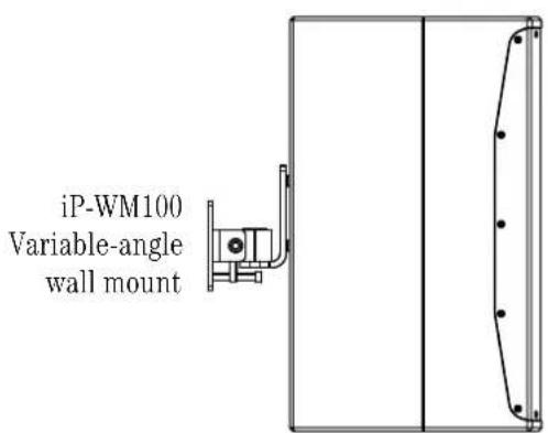
| Optional Accessories | iP-CM100 ceiling mount, iP-WM100 wall mount, PA-A2 eyebolt kit, SP260 processor |
| Cleaning | Dry cloth or damp cloth with mild soap; avoid moisture in openings |
| Safety | Do not expose to rain or moisture; see manual for full safety instructions |
Frequently Asked Questions - iP-12 MACKIE
User questions about iP-12 MACKIE
0 question about this device. Answer the ones you know or ask your own.
Ask a new question about this device
Download the instructions for your Loudspeaker in PDF format for free! Find your manual iP-12 - MACKIE and take your electronic device back in hand. On this page are published all the documents necessary for the use of your device. iP-12 by MACKIE.
USER MANUAL iP-12 MACKIE
natural_image
Four black rectangular electronic devices with circular connectors, arranged side by side (no visible text or symbols)Important Safety Instructions
- Read these instructions.
- Keep these instructions.
- Heed all warnings.
- Follow all instructions.
- Do not use this apparatus near water.
- Clean only with a dry cloth.
- Do not block any ventilation openings. Install in accordance with the manufacturer's instructions.
- Do not install near any heat sources such as radiators, heat registers, stoves, or other apparatus (including amplifiers) that produce heat.
-
Only use attachments/accessories specified by the manufacturer.
-
Use only with a cart, stand, tripod, bracket, or table specified by the manufacturer, or sold with the apparatus. When a cart is used, use caution when moving the cart/apparatus combination to avoid injury from tip-over.
-
Refer all servicing to qualified service personnel. Servicing is required when the apparatus has been damaged in any way, such as power-supply cord or plug is damaged, liquid has been spilled or objects have fallen into the apparatus, the apparatus has been exposed to rain or moisture, does not operate normally, or has been dropped.
- Exposure to extremely high noise levels may cause permanent hearing loss. Individuals vary considerably in susceptibility to noise-induced hearing loss, but nearly everyone will lose some hearing if exposed to sufficiently intense noise for a period of time. The U.S. Government's Occupational Safety and Health Administration (OSHA) has specified the permissible noise level exposures shown in the following chart.
According to OSHA, any exposure in excess of these permissible limits could result in some hearing loss. To ensure against potentially dangerous exposure to high sound pressure levels, it is recommended that all persons exposed to equipment capable of producing high sound pressure levels use hearing protectors while the equipment is in operation. Ear plugs or protectors in the ear canals or over the ears must be worn when operating the equipment in order to prevent permanent hearing loss if exposure is in excess of the limits set forth here:
| Duration, per day in hours | Sound Level dBA, Slow Response | Typical Example |
| 8 | 90 | Duo in small club |
| 6 | 92 | |
| 4 | 95 | Subway Train |
| 3 | 97 | |
| 2 | 100 | Very loud classical music |
| 1.5 | 102 | |
| 1 | 105 | Troy screaming at Karl about deadlines |
| 0.5 | 110 | |
| 0.25 or less | 115 | Loudest parts at a rock concert |
WARNING — To reduce the risk of fire or electric shock, do not expose this apparatus to rain or moisture.
Correct Disposal of this product: This symbol indicates that this product should not be disposed of with your household waste, according to the WEEE Directive (2012/19/EU) and your national law. This product should be handed over to an authorized collection site for recycling waste electrical and electronic equipment (EEE). Improper handling of this type of waste could have a possible negative impact on the environment and human health due to potentially hazardous substances that are generally associated with EEE. At the same time, your cooperation in the correct disposal of this product will contribute to the effective usage of natural resources. For more information about where you can drop off your waste equipment for recycling, please contact your local city office, waste authority, or your household waste disposal service.
Please write the serial number for your loudspeaker(s) here for future reference:
Loudspeaker 1
Loudspeaker 2
Loudspeaker 3
Loudspeaker 4
Purchased at: Date of Purchase:
Don't forget to visit our website at www.720trees.com for more information about this and other products.
Part No. SW1081 Rev. A 12/14
©2014 LOUD Technologies Inc. All Rights Reserved.
Contents
IMPORTANT SAFETY INSTRUCTIONS ...... 2
CONTENTS....3
INTRODUCTION 3
FEATURES 3
HOW TO USE THIS MANUAL......4
GETTING STARTED......4
THINGS TO REMEMBER 4
HOOKUP DIAGRAMS...... 5
PLACEMENT....7
ROOM ACOUSTICS....7
RIGGING 8
PROTECTION 10
AMPLIFIER POWER 10
RECOMMENDED POWER RATINGS .... 10
PREVENTING LOUDSPEAKER DAMAGE 10
APPENDIX A: SERVICE INFORMATION......11
APPENDIX B: CONNECTIONS 12
APPENDIX C: SPECIFICATIONS AND DIMENSIONS ... 13
LIMITED WARRANTY....15
Introduction
iP Series Install Performance Loudspeakers are designed exclusively for a wide range of installed sound reinforcement applications. Behind each iP loudspeaker's clean, professional look are high-output, custom-designed woofers and premium 1.4" titanium diaphragm compression drivers delivering rich, articulate full-bandwidth response. Ample rigging points support vertical and horizontal rigging and a choice of Neutrik® or terminal connections provides install flexibility. Optional ceiling and wall mounts are available for aesthetically demanding venues. Plus, the companion iP-18S 18" subwoofer is perfect for additional low-frequency response and output in larger applications. Add the SP260 speaker processor with iP presets for quick setup and flawless sonic performance.


Like us
Follow us
Watch our dang videos
Features
iP Full-Range Models:
- Low-profile installation loudspeaker.
-
High-output ceramic woofer with voice coil for maximum output.
-
iP-10 - 10" woofer / 2" voice coil
- iP-12 - 12" woofer / 2.5" voice coil
- iP-15 – 15" woofer / 2.5" voice coil
- 1.4" titanium compression driver provides smooth, consistent high-frequency response.
- 8 × M10 rigging points and rotatable 90^ × 50^ horn for vertical/horizontal rigging (PA-A2 accessory).
-
Optional ceiling and wall mount accessories meet the needs of the most aesthetically demanding venues (iP-CM100 & iP-WM100 accessories).
-
Rotatable center logo allows for clean presentation in all configurations.
- Convenient terminal strip connectivity saves time and cost.
- Dual Neutrik ^ parallel connectors.
- Lightweight, compact and durable 15mm poplar cabinet construction.
- Companion iP-18S 18" subwoofer extends low-frequency response and increases output in larger applications.
- Optional SP260 2 × 6 speaker processor delivers iP presets to get your system quickly dialed in.
iP-18S Subwoofer:
- 18" high-output installation subwoofer.
- 18" high-output ceramic woofer with 3" voice coil for maximum output.
- Convenient terminal strip connectivity saves time and cost.
- Dual Neutrik® parallel connectors.
- Lightweight, compact and durable 15mm poplar cabinet construction.
- Optional SP260 2 × 6 speaker processor delivers iP presets to get your system quickly dialed in.
How to Use This Manual
After this introduction, a getting started guide will help you get things set up fast. The hook-up diagrams show some typical setups.

This icon marks information that is critically important or unique to the loudspeaker. For your own good, read and remember them.

This icon leads you to in-depth explanations of features and practical tips. They usually have some valuable nuggets of information.
Appendix A is a section on troubleshooting and repair. Appendix B is a section on connectors.
Appendix C shows the technical specifications.
Getting Started
The following steps will help you set up your loudspeakers quickly.
- Make all initial connections with the power switches OFF on all equipment. Make sure the master volume, level, or gain controls are all the way down.
- Connect the line-level outputs from your mixing console (or other signal source) to the inputs of your power amplifier.
- Connect the "Speaker Output" from your power amplifier (or powered mixer) to the INPUT connector on the iP Series speaker (NL4 jack).
- If you are using the iP-18S subwoofer with one of the full-range loudspeakers, connect the NL4 THRU to the subwoofer's input.
- Turn on your mixing console (or other signal source).
- Turn on the amplifier. Turn up its volume or gain control(s) as recommended by the manufacturer.
- Start the signal source, whether it be speaking into a microphone or starting a CD player. Adjust the volume controls on the mixer (or other signal source) for normal operation.
Things to Remember:
- Never listen to loud music for prolonged periods. Please see the Safety Instructions on page 2 for information on hearing protection.
- When you shut down your equipment, turn off the amplifiers first to prevent thumps and other noises generated by any upstream equipment from coming out of the speakers. When powering up, turn on the amplifiers last.
- Save the shipping boxes and packing materials! You may need them someday. Besides, your cat will love playing in them and jumping out at you unexpectedly. Remember to pretend like you are surprised!
- Save your sales receipt in a safe place.
- Record the serial numbers in the spaces provided on page 2, along with where and when you bought them.
Hookup Diagrams
Two iP-12's with a Mixer and Power Amplifier

The left and right line-level outputs from a mixer feed the inputs of a power amplifier. The speaker outputs of the power amplifier feed the inputs of two iP-12 loudspeakers.
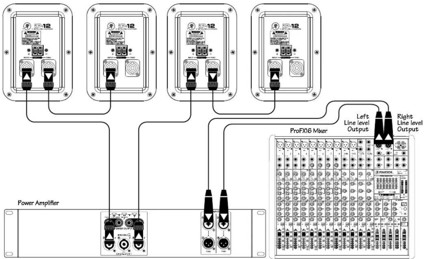
Four iP-12's with a Mixer and Power Amplifier, Daisy-Chaining
flowchart
graph TD
    A["Power Amplifier"] --> B["ProFX16 Mixer"]
    B --> C["Left Line level Output"]
    B --> D["Right Line level Output"]
    E["iP-12"] --> F["Power Amplifier"]
    G["iP-12"] --> H["ProFX16 Mixer"]
    I["iP-12"] --> J["Power Amplifier"]
    K["iP-12"] --> L["ProFX16 Mixer"]
    M["iP-12"] --> N["Power Amplifier"]
    O["iP-12"] --> P["ProFX16 Mixer"]
The left and right line-level outputs from a mixer feed the inputs of a power amplifier. The speaker outputs of the power amplifier feed the inputs of two iP-12 loudspeakers. Their respective THRU jacks feed the inputs of another pair of iP-12 loudspeakers.
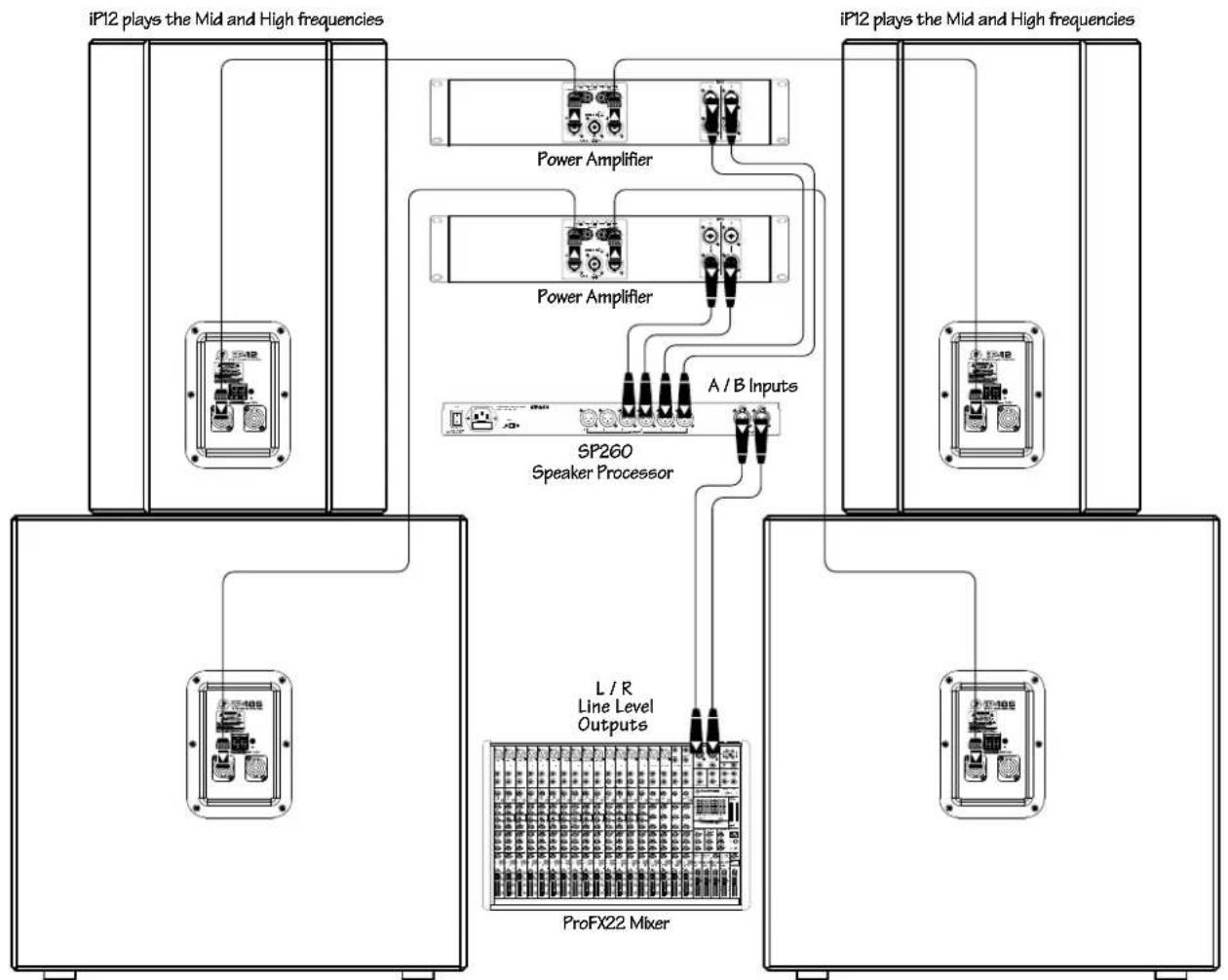
Two iP-12 Loudspeakers Daisy-Chained with Two iP-18S Subwoofers
flowchart
graph TD
    A["iP12 plays the Mid and High frequencies"] --> B["Power Amplifier"]
    A --> C["Power Amplifier"]
    A --> D["A / B Inputs"]
    B --> E["SP260 Speaker Processor"]
    C --> E
    D --> E
    E --> F["L / R Line Level Outputs"]
    E --> G["ProFX22 Mixer"]
    H["iP12 plays the Mid and High frequencies"] --> I["Power Amplifier"]
    H --> J["Power Amplifier"]
    H --> K["A / B Inputs"]
    H --> L["L / R Line Level Outputs"]
    H --> M["ProFX22 Mixer"]
iP18S plays the Low frequencies
iP18S plays the Low frequencies
iP loudspeakers may be used with iP-18S subwoofers to create an incredibly powerful system. Here, the left and right line-level outputs from a mixer feed the inputs of an SP260 speaker processor. The channel 1 and 2 outputs of the SP260 feed the inputs of a power amplifier. The speaker outputs of this power amplifier feed the inputs of the left and right iP-12 mains. The channel 3 and 4 outputs of the SP260 feed the inputs of a second power amplifier. The speaker outputs of this power amplifier feed the inputs of the left and right iP-18S subwoofers, whose internal low-pass filters allow the subwoofers to reproduce only the lowest frequencies.
Placement
iP loudspeakers are designed for permanent installation, hence the name! iP loudspeakers can be mounted on the ceiling or wall and may also be flown via its mounting points. See pages 8–9 on rigging. They may also sit on the floor or stage.
As with any loudspeakers, protect them from moisture. If you are setting them up outdoors, make sure they are under cover if you expect rain.
Room Acoustics
The iP Series loudspeakers are designed to sound as neutral as possible. However, room acoustics play a crucial role in the overall performance of a sound system. Here are some placement tips to get the best performance from the iP Series loudspeakers:
- Avoid placing loudspeakers in the corners of a room. This increases the low-frequency output and can cause the sound to be muddy and indistinct.
- Avoid placing loudspeakers against a wall. This, too, increases the low-frequency output, though not as much as corner placement. However, if you do need to reinforce the low frequencies, this is a good way to do it.
- Avoid placing the loudspeakers directly on a hollow stage floor. A hollow stage can resonate at certain frequencies, causing peaks and dips in the frequency response of the room. It is better to place the loudspeakers on a sturdy table or tripod stands.
- Position the loudspeakers so the high-frequency drivers are a foot or more above ear level for the audience. (Make allowances for a standing / dancing-in-the-aisles audience). High frequencies are highly directional and tend to be absorbed much easier than lower frequencies. By providing direct line-of-sight from the loudspeakers to the audience, you increase the overall brightness and intelligibility of the sound system.
- Highly reverberant rooms, like many gymnasiums and auditoriums, are a nightmare for sound system intelligibility. Multiple reflections off the hard walls, ceiling and floor play havoc with the sound. Depending on the situation, you may be able to take some steps to minimize the reflections, such as putting carpet on the floors, closing draperies to cover large glass windows, or hanging tapestries or other materials on the walls to absorb some of the sound.
However, in most cases, these remedies are not possible or practical. So what do you do? Making the sound system louder generally doesn't work because the reflections become louder, too. The best approach is to provide as much direct sound coverage to the audience as possible.. The farther away you are from the loudspeaker, the more prominent will be the reflected sound.
Use more speakers strategically placed so they are closer to the back of the audience. If the distance between the front and back speakers is more than 100 feet, you should be able to use a delay processor to time-align the sound. Since sound travels about one foot per millisecond, it takes 1/10 of a second to travel 100 feet.
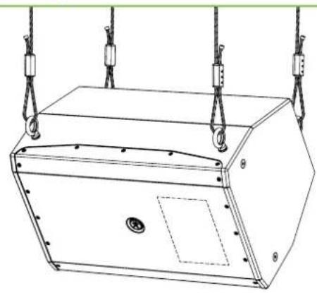
Rigging
iP Series loudspeakers may be individually flown using a PA-A2 Eyebolt Kit, part number 0028272 [M10 × 1.5 × 37 mm forged shoulder eyebolts].

WARNING: Installation should only be done by an experienced technician. Improper installation may result in damage to the equipment, injury or death. Make sure that the loudspeaker is installed in a stable and secure way in order to avoid any conditions that may be dangerous for persons or structures.
Rigging Design Practices
Rigging a loudspeaker requires determining:
- The rigging methods and hardware that meet static, shock, dynamic, and any other load requirements for supporting the loudspeaker from structure.
- The design factor and required WLL (Working Load Limit) for this support.
We strongly recommend the following rigging practices:
- Documentation: Thoroughly document the design with detailed drawings and parts lists.
- Analysis: Have a qualified professional, such as a licensed Professional Engineer, review and approve the design before its implementation.
- Installation: Have a qualified professional rigger do the installation and inspection.
- Safety: Use adequate safety precautions and backup systems.
Rigging Hardware and Accessories
Rigging our loudspeakers will invariably require hardware not supplied by us. Various types of load-rated hardware are available from a variety of third-party sources. There are a number of such companies specializing in manufacturing hardware for, designing, and installing rigging systems. Each one of these tasks is a discipline in its own right. Because of the hazardous nature of rigging work and the potential liability, engage companies that specialize in these disciplines to do the work required.
We do offer certain accessory rigging items and some of them may be used with a variety of products. While these accessories are intended to facilitate installation, the wide variety of possible installation conditions and array configurations do not permit us to determine their suitability or load rating for any particular application.
We are not in the business of providing complete rigging systems, either as designers, manufacturers, or installers. It is the responsibility of the installer to provide a properly engineered, load-certified rigging system for supporting the loudspeaker from structure.
Rigging Notes
The iP Series loudspeaker's integral mounting points are designed to support only the weight of their own loudspeaker with suitable, external hardware. This means that each iP Series loudspeaker must be supported independently of any other iP Series loudspeaker and any other loads. At least three rigging points must be used to hang an iP Series loudspeaker.
8 Fly Points [iP-10 / iP-12 / iP-15]
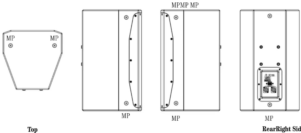
RearRight Side Left Side
Rigging Configurations
The iP Series have M10 inserts on the top, rear and both the left and right sides. This allows the iP to be flown vertically, in horizontal applications, it can be flown with the horn in the left or right orientation to suit your application.
Vertical:

Important Rigging Reminder:
To reiterate, we are not in the business of providing complete rigging systems, either as designers, manufacturers, or installers. It is the responsibility of the installer to provide a properly engineered, load-certified rigging system for supporting the loudspeaker from structure.
Horizontal Left:

natural_image
Technical line drawing of a mechanical enclosure with hanging weights and mounting holes (no text or symbols)Horizontal Right:
natural_image
Technical line drawing of a mechanical device with suspended weights and mounting holes (no text or symbols)Ceiling mounted:

Wall mounted:
Protection
A protection circuit is built into the iP-10, iP-12 and iP-15 to protect their high-frequency drivers from excessive power. When tripped, the protection circuit substantially reduces the power to the HF driver. After the driver cools to a safe operating temperature, the protection circuit resets and normal operation resumes. However, if the protection circuit senses excessive power, it will trip again. In this case, it is necessary to reduce the power to the loudspeaker by either turning down the gain controls on the power amplifier or turning down the master volume control on the mixer or other sound source.

CAUTION: The protection circuit is designed to protect the HF driver under reasonable and sensible conditions. Should you choose to ignore the warning signs (i.e., frequent clip LED indications on the mixer or power amplifier, excessive distortion), you can still damage the drivers in the iP Series loudspeakers by overdriving them past their recommended amplifier power-handling ratings, or past the point of amplifier clipping. Such damage is beyond the scope of the warranty.
Amplifier Power
The iP Series loudspeakers have three power-handling numbers: continuous, program and peak. So how much power do you really need to drive these loudspeakers? The answer to that question depends on what type of program material you are running through the system and how loud it needs to be.
Some audio signals have lots of momentary peaks whose amplitudes extend far above the average overall level of the program. Percussion instruments are a good example of this. Other types of signals, like highly compressed rock music, have a higher average signal level with fewer peaks. Speech reinforcement requires less power overall, but involves large moment-to-moment variations in level.
Assuming you want to use the full capability of the loudspeaker, and the program contains at least some momentary peaks, we recommend that you use an amplifier that is rated at twice the continuous power rating of the loudspeaker (into 8 ohms). For the iP-10 loudspeakers, this would be 200 watts × 2 = 400 watts per channel into 8 ohms. This ensures that the amplifier can reproduce peaks that are 6 dB higher than the continuous (rms) power-handling rating before clipping occurs.
Recommended Power Ratings
- iP-10: 400 watts into 8 ohms (200 watts rms × 2)
- iP-12: 500 watts into 4 ohms (300 watts rms × 2)
- iP-15: 600 watts into 8 ohms (300 watts rms × 2)
- iP-18S: 800 watts into 8 ohms (400 watts rms × 2)
Preventing Loudspeaker Damage
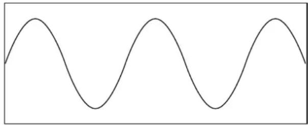
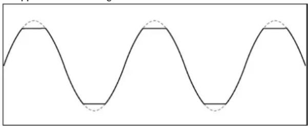
Speaking of clipping, this is likely the number one cause of damage to loudspeakers. Clipping occurs when the signal at the output of any device in the system (not just the amplifier) reaches its maximum level. The input signal to the device may continue to increase, but the output simply stops, and is characterized by a "flat-top" appearance to the waveform.
Normal Sine Wave Signal 😊
natural_image
Simple sine wave pattern with no text or symbolsClipped Sine Wave Signal 😊
natural_image
Pure sine wave pattern with no text, numbers, or symbolsClipping interrupts the motion of the transducer, creating distortion and excessive heat in the driver, which can damage it over time.
Some folks think that if they use a power amplifier whose power rating is below the maximum power-handling rating of the loudspeaker, then they can't possibly damage the loudspeaker. But if the amplifier is driven into clipping, even a lower power amplifier can damage the loudspeaker.
The bottom line is that to prevent damage to the loudspeakers, you must have a properly operating sound system. Proper operation of a sound system includes being aware of types of audio signals being reproduced, controlling the output levels accordingly, and operating all the devices in the system so that no clipping occurs within the signal chain.
Appendix A: Service Information
If you think your product has a problem, please check out the following troubleshooting tips and do your best to confirm the problem. Visit the Support section of our website (www.720trees.com) to get some ideas or contact our technical support heroes. You may find the answer to the problem without having to send your product away.
Troubleshooting
No Sound
- Are the level controls on the mixer or amplifier turned all the way down? Follow the procedures in “Getting Started” section on page 4 to verify that all of the volume controls in the system are properly adjusted.
- Is the signal source working (and making union scale)?
- Are all the connections good and sound? Make sure all of the connecting cables are in good repair and securely connected at both ends.
One side is way louder than the other!
- Are the level controls set the same for both channels on the mixer and amplifier?
- Check the pan control on the signal source. It may be turned too far to one side. If you're using a stereo signal source, it may be delivering an out-of-balance stereo signal.
- Try switching sides: Turn off the amp, swap the speaker cables at the amp and turn the amp back on. If the same side is still louder, the problem is with your speaker cabling or the loudspeakers. If the other side is louder now, the problem is with the mixer, the loudspeaker processor, the amp, or the line-level cabling.
Poor bass performance
- Check the polarity of the connections between the amplifier and the loudspeakers. You may have your positive and negative connections reversed at one end of one cable.
Bad Sound
- Is the input connector plugged completely into the jack? Make sure it is plugged all the way in.
- Is it loud and distorted? Reduce the signal level at the mixer.
- If possible, listen to the signal source with headphones plugged into the preamp stage. If it sounds bad there, it's not the loudspeaker.
- Too much bass or not enough bass? Move around the room and see if the bass response changes. It's possible your listening position coincides with a room mode where the low frequencies either become exaggerated or nulled. If so, try moving the loudspeakers to a different position, or moving your listening position.
Care and Maintenance
Your loudspeakers will provide many years of reliable service if you follow these simple guidelines:
- Avoid exposing the loudspeakers to moisture. If they are set up outdoors, be sure they are under cover if you expect rain.
- Avoid exposure to extreme cold (below freezing temperatures). If you must operate the loudspeakers in a cold environment, warm up the voice coils slowly by sending a low-level signal through them for about 15 minutes prior to high-power operation.
- Use a damp cloth with a mild soap solution to clean the cabinets. Avoid getting moisture into any of the openings of the cabinet, particularly where the drivers are located.
Repair
For warranty service, refer to the warranty information on page 15.
Non-warranty service for products is available at a factory-authorized service center. To locate your nearest service center, visit www.720trees.com, click "Support" and select "Locate a Service Center." Service for products living outside the United States can be obtained through local dealers or distributors.
If you do not have access to our website, you can call our Tech Support department at 1-800-898-3211, Monday-Friday during normal business hours, Pacific Time, to explain the problem. Tech Support will tell you where the nearest factory-authorized service center is located in your area.
Appendix B: Connections
The iP Series loudspeakers have NL4 input and thru connectors. The connectors are wired in parallel, so use only one of the input connectors.
NL4
These connectors are designed to handle the higher currents produced by amplifiers and have a locking feature to prevent accidental disconnections. Simply line up the tabs on the plug with the jack on the iP Series loudspeaker, push it in and rotate it clockwise 1/4 turn to lock it in place.
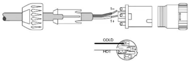
NL4 Connector
Pin 1 - = Cold (-)
Pin 1 + = Hot (+)
Pin 2 - = No Connection
Pin 2 + = No Connection
+/- TERMINAL CONNECTIONS
Use a pair of wire strippers to strip 3/4" of insulation from speaker wire. Bend the end of the exposed copper wire into a half-circle. Turn the screws counterclockwise and wrap the curved wire around the terminal with the open end towards the right (this allows for better connection when tightening). Once the wires are firmly attached then tighten the screws by turning them clockwise.

Appendix C: iP Series Specifications
iP-10
System
Type: Two-way, full-range loudspeaker
Frequency Range (-10 dB): 50 Hz - 20 kHz
Horizontal Coverage Angle: 90°
Vertical Coverage Angle: 50°
Nominal Impedance: 8 ohms
Power Handling: 200 watts continuous
400 watts program
124dB-SPL max output
Crossover Frequency: 3 kHz
Transducers
Low Frequency: 10" / 254 mm woofer, vented
High Frequency: 1.4" / 35 mm titanium
dome compression driver
Physical
Input / Output Connectors: 2× Neutrik NL4MP
2-point screw terminal strip
Enclosure: 15 mm poplar w/ lightly textured
black paint
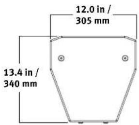
Dimensions
Height: 20.5 in / 520 mm
Width: 12.0 in / 310 mm
Depth: 13.4 in / 340 mm
Weight: 26 lb / 11.8 kg
iP-12
System
Type: Two-way, full-range loudspeaker
Frequency Range (-10 dB): 45 Hz - 20 kHz
Horizontal Coverage Angle: 90°
Vertical Coverage Angle: 50°
Nominal Impedance: 4 ohms
Power Handling: 250 watts continuous
500 watts program
128dB-SPL max output
Crossover Frequency:
2.2 kHz
Transducers
Low Frequency: 12" / 310 mm woofer, vented
High Frequency: 1.4" / 35 mm titanium
dome compression driver
Physical
Input / Output Connectors: 2× Neutrik NL4MP
2-point screw terminal strip
Enclosure: 15 mm poplar w/ lightly textured
black paint
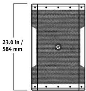
Dimensions
Height: 23.0 in / 585 mm
Width: 14.2 in / 360 mm
Depth: 14.9 in / 377 mm
Weight: 34.2 lb / 15.5 kg
iP-10 Dimensions

iP-12 Dimensions

iP-15
System
Type: Two-way, full-range loudspeaker
Frequency Range (-10 dB): 40 Hz - 20 kHz
Horizontal Coverage Angle: 90°
Vertical Coverage Angle: 50°
Nominal Impedance: 8 ohms
Power Handling: 300 watts continuous
600 watts program
126dB-SPL max output
Crossover Frequency: 2.5 kHz
Transducers
Low Frequency: 15" / 381 mm woofer, vented
High Frequency: 1.4" / 35 mm titanium dome compression driver
Physical
| Input / Output Connectors: | 2× Neutrik NL4MP2-point screw terminal strip |
| Enclosure: | 15 mm poplar w/ lightly texturedblack paint |
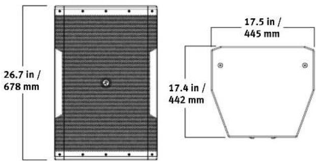
| Dimensions | |
| Height: | 26.7 in / 677 mm |
| Width: | 17.5 in / 445 mm |
| Depth: | 17.4 in / 441 mm |
| Weight: | 45.2 lb / 20.5 kg |
iP-18S
System
Type: Subwoofer
Frequency Range (-10 dB): 35 Hz - 150 Hz
Nominal Impedance: 8 ohms
Power Handling: 400 watts continuous
800 watts program
132dB SPL max output
Internal Low Pass Filter: 115 Hz
Transducers
Low Frequency: 18" / 457 mm woofer, vented
Physical
Input / Output Connectors: 2× Neutrik NL4MP 2-point screw terminal strip
Enclosure: 15 mm poplar w/ lightly textured black paint
Dimensions
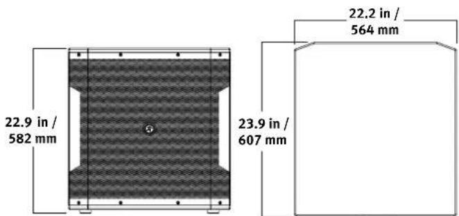
Height: 22.9 in / 581 mm
Width: 22.2 in / 565 mm
Depth: 23.9 in / 608 mm
Weight: 58.8 lb / 26.7 kg
iP-15 Dimensions
iP-18S Dimensions
LOUD Technologies Inc. is always striving to improve our products by incorporating new and improved materials, components, and manufacturing methods. Therefore, we reserve the right to change these specifications at any time without notice. The "Running Man" is a registered trademark of LOUD Technologies Inc. All other brand names mentioned are trademarks or registered trademarks of their respective holders, and are hereby acknowledged. ©2014 LOUD Technologies Inc. All Rights Reserved.
Please keep your sales receipt in a safe place.
This Limited Product Warranty (“Product Warranty”) is provided by LOUD Technologies Inc. (“LOUD”) and is applicable to products purchased in the United States or Canada through a LOUD-authorized reseller or dealer. The Product Warranty will not extend to anyone other than the original purchaser of the product (hereinafter, “Customer,” “you” or “your”).
For products purchased outside the U.S. or Canada, please visit www.720trees.com/warranty to find contact information for your local distributor, and information on any warranty coverage provided by the distributor in your local market.
LOUD warrants to Customer that the product will be free from defects in materials and workmanship under normal use during the Warranty Period. If the product fails to conform to the warranty then LOUD or its authorized service representative will at its option, either repair or replace any such nonconforming product, provided that Customer gives notice of the noncompliance within the Warranty Period to the Company at: www.720trees.com/support or by calling LOUD technical support at 1.800.898.3211 (toll-free in the U.S. and Canada) during normal business hours Pacific Time, excluding weekends or LOUD holidays. Please retain the original dated sales receipt as evidence of the date of purchase. You will need it to obtain any warranty service.
For full terms and conditions, as well as the specific duration of the Warranty for this product, please visit www.720trees.com/warranty.
The Product Warranty, together with your invoice or receipt, and the terms and conditions located at www.720trees.com/warranty constitutes the entire agreement, and supersedes any and all prior agreements between LOUD and Customer related to the subject matter hereof. No amendment, modification or waiver of any of the provisions of this Product Warranty will be valid unless set forth in a written instrument signed by the party to be bound thereby.
Need help with your loudspeaker?
- Visit www.720trees.com and click Support to find: FAQs, manuals, addendums, and other documents.
- Email us at: techmail@loudtechinc.com.
- Telephone 1-800-898-3211 to speak with one of our splendid technical support chaps (Monday through Friday, normal business hours, Pacific Time).

MACKIE.
16220 Wood-Red Road NE
Woodinville, WA 98072 • USA
Phone: 425.487.4333
Toll-free: 800.898.3211
Fax: 425.487.4337
www.720trees.com


- Important Safety Instructions
- Contents
- Introduction
- Features
- iP Full-Range Models:
- iP-18S Subwoofer:
- How to Use This Manual
- Getting Started
- Things to Remember:
- Hookup Diagrams
- Two iP-12 Loudspeakers Daisy-Chained with Two iP-18S Subwoofers
- Placement
- Room Acoustics
- Rigging
- Rigging Design Practices
- Rigging Hardware and Accessories
- Rigging Notes
- Rigging Configurations
- Important Rigging Reminder:
- Protection
- Amplifier Power
- Recommended Power Ratings
- Preventing Loudspeaker Damage
- Appendix A: Service Information
- Troubleshooting
- No Sound
- One side is way louder than the other!
- Poor bass performance
- Bad Sound
- Care and Maintenance
- Repair
- Appendix B: Connections
- NL4
- +/- TERMINAL CONNECTIONS
- Appendix C: iP Series Specifications
- iP-10
- System
- Transducers
- Physical
- iP-12
- iP-10 Dimensions
- iP-12 Dimensions
- iP-15
- iP-18S
- iP-15 Dimensions
- iP-18S Dimensions
- Please keep your sales receipt in a safe place.
- Need help with your loudspeaker?
- MACKIE.
Brand : MACKIE
Model : iP-12
Category : Loudspeaker