
AG700 - Angle Grinder RYOBI - Free user manual and instructions
Find the device manual for free AG700 RYOBI in PDF.


| Product Type | Angle Grinder |
| Model | AG700 |
| Brand | RYOBI |
| Disc Diameter | 4-1/2" (115 mm) |
| Spindle Thread | 5/8"-11 UNC |
| No-Load Speed | 11,000 RPM |
| Power Input | 6.5 A, 120 V, 60 Hz AC |
| Power Output | 700 W (approx.) |
| Dimensions (L x W x H) | 11.5 x 4.5 x 5.5 in (292 x 114 x 140 mm) |
| Weight | 5.1 lb (2.3 kg) |
| Main Functions | Grinding, cutting, sanding, wire brushing |
| Included Accessories | Side handle, wheel guard, flange nut, wrench |
| Maintenance | Clean air vents regularly; inspect and replace carbon brushes every 50-100 hours |
| Safety Features | Two-position side handle, wheel guard, spindle lock, double insulation |
| Spare Parts | Carbon brushes (part # 410275001), switch, armature |
| Repairability | User-replaceable brushes; professional repair recommended for other issues |
| Certifications | UL listed |
Frequently Asked Questions - AG700 RYOBI
User questions about AG700 RYOBI
0 question about this device. Answer the ones you know or ask your own.
Ask a new question about this device
Download the instructions for your Angle Grinder in PDF format for free! Find your manual AG700 - RYOBI and take your electronic device back in hand. On this page are published all the documents necessary for the use of your device. AG700 by RYOBI.
USER MANUAL AG700 RYOBI
7 in. MULTI-PURPOSE GRINDER DOUBLE INSULATED
AG700
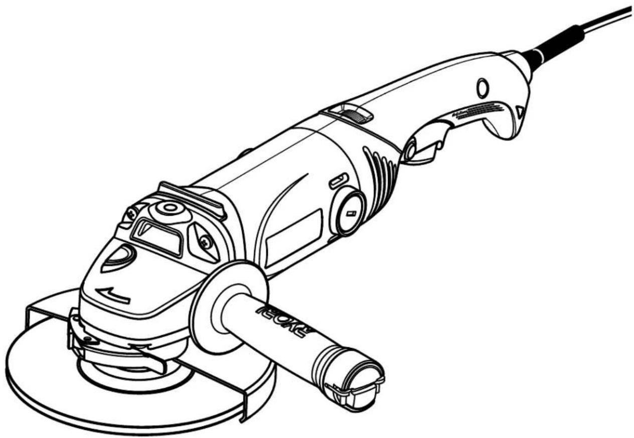
This product has been engineered and manufactured to our high standard for dependability, ease of operation, and operator safety. When properly cared for, it will give you years of rugged, trouble-free performance.

WARNING: To reduce the risk of injury, the user must read and understand the operator's manual before using this product.
Thank you for your purchase.
SAVE THIS MANUAL FOR FUTURE REFERENCE
TABLE OF CONTENTS
■ Introduction....2
■ Warranty .... 2
■ General Safety Rules....3-4
■ Specific Safety Rules....4-6
■ Symbols....7-8
■ Electrical....9
■ Features....10-11
■ Assembly 11-12
■ Operation....12-18
■ Maintenance....19-21
■ Parts Ordering / Service ....Back Page
INTRODUCTION
This product has many features for making its use more pleasant and enjoyable. Safety, performance, and dependability have been given top priority in the design of this product making it easy to maintain and operate.
WARRANTY
RYOBI® POWER TOOL - LIMITED TWO YEAR WARRANTY AND 30 DAY EXCHANGE POLICY
One World Technologies, Inc., warrants its RYOBI® power tools with the following conditions:
30-DAY EXCHANGE POLICY: During the first 30 days after date of purchase, you may either request service under this warranty or you may exchange any RYOBI® power tool which does not work properly due to defective workmanship or materials by returning the power tool to the dealer from which it was purchased. To receive a replacement power tool or requested warranty service, you must present proof of purchase and return all original equipment packaged with the original product. The replacement power tool will be covered by the limited warranty for the balance of the two year period from the date of the original purchase.
WHAT THIS WARRANTY COVERS: This warranty covers all defects in workmanship or materials in your RYOBI® power tool for a period of two years from the date of purchase. With the exception of batteries, power tool accessories are warranted for ninety (90) days. Batteries are warranted for two years.
HOW TO GET SERVICE: Just return the power tool, properly packaged and postage prepaid, to an Authorized Service Center. You can obtain the location of the Service Center nearest you by contacting a service representative at One World Technologies, Inc., P.O. Box 1207, Anderson, SC 29622-1207, by calling 1-800-525-2579 or by logging on to www.ryobitools.com. When you request warranty service, you must also present proof of purchase documentation, which includes the date of purchase (for example, a bill of sale). We will repair any faulty workmanship, and either repair or replace any defective part, at our option. We will do so without any charge to you. We will complete the work in a reasonable time, but, in any case, within ninety (90) days or less.
WHAT'S NOT COVERED: This warranty applies only to the original purchaser at retail and may not be transferred. This warranty only covers defects arising under normal usage and does not cover any malfunction, failure or defects resulting from misuse, abuse, neglect, alteration, modification or repairs by other than Authorized Service Centers. One World Technologies, Inc. makes no warranties, representations or promises as to the quality or performance of its power tools other than those specifically stated in this warranty.
ADDITIONAL LIMITATIONS: Any implied warranties granted under state law, including warranties of merchantability or fitness for a particular purpose, are limited to two years from the date of purchase. One World Technologies, Inc. is not responsible for direct, indirect, or incidental damages, so the above limitations and exclusions may not apply to you. This warranty gives you specific legal rights, and you may also have other rights which vary from state to state.
GENERAL SAFETY RULES

WARNING!
Read all instructions. Failure to follow all instructions listed below may result in electric shock, fire and/or serious injury. The term “power tool” in all of the warnings listed below refers to your mains-operated (corded) power tool or battery-operated (cordless) power tool.
SAVE THESE INSTRUCTIONS
WORK AREA SAFETY
- Keep work area clean and well lit. Cluttered or dark areas invite accidents.
■ Do not operate power tools in explosive atmospheres, such as in the presence of flammable liquids, gases or dust. Power tools create sparks which may ignite the dust or fumes. - Keep children and bystanders away while operating a power tool. Distractions can cause you to lose control.
ELECTRICAL SAFETY
■ Power tool plugs must match the outlet. Never modify the plug in any way. Do not use any adapter plugs with earthed (grounded) power tools. Unmodified plugs and matching outlets will reduce risk of electric shock.
■ Avoid body contact with earthed or grounded surfaces such as pipes, radiators, ranges and refrigerators. There is an increased risk of electric shock if your body is earthed or grounded.
■ Do not expose power tools to rain or wet conditions. Water entering a power tool will increase the risk of electric shock.
- Do not abuse the cord. Never use the cord for carrying, pulling or unplugging the power tool. Keep cord away from heat, oil, sharp edges or moving parts. Damaged or entangled cords increase the risk of electric shock.
■ When operating a power tool outdoors, use an extension cord suitable for outdoor use. Use of a cord suitable for outdoor use reduces the risk of electric shock.
PERSONAL SAFETY
■ Stay alert, watch what you are doing and use common sense when operating a power tool. Do not use a power tool while you are tired or under the influence of drugs, alcohol or medication. A moment of inattention while operating power tools may result in serious personal injury.
■ Use safety equipment. Always wear eye protection. Safety equipment such as dust mask, non-skid safety shoes, hard hat, or hearing protection used for appropriate conditions will reduce personal injuries.
■ Avoid accidental starting. Ensure the switch is in the off-position before plugging in. Carrying power tools
with your finger on the switch or plugging in power tools that have the switch on invites accidents.
■ Remove any adjusting key or wrench before turning the power tool on. A wrench or a key left attached to a rotating part of the power tool may result in personal injury.
- Do not overreach. Keep proper footing and balance at all times. This enables better control of the power tool in unexpected situations.
■ Dress properly. Do not wear loose clothing or jewelry. Keep your hair, clothing and gloves away from moving parts. Loose clothes, jewelry or long hair can be caught in moving parts.
If devices are provided for the connection of dust extraction and collection facilities, ensure these are connected and properly used. Use of these devices can reduce dust-related hazards.
■ Do not wear loose clothing or jewelry. Contain long hair. Loose clothes, jewelry, or long hair can be drawn into air vents.
■ Do not use on a ladder or unstable support. Stable footing on a solid surface enables better control of the power tool in unexpected situations.
POWER TOOL USE AND CARE
- Do not force the power tool. Use the correct power tool for your application. The correct power tool will do the job better and safer at the rate for which it was designed.
- Do not use the power tool if the switch does not turn it on and off. Any power tool that cannot be controlled with the switch is dangerous and must be repaired.
■ Disconnect the plug from the power source and/or the battery pack from the power tool before making any adjustments, changing accessories, or storing power tools. Such preventive safety measures reduce the risk of starting the power tool accidentally.
■ Store idle power tools out of the reach of children and do not allow persons unfamiliar with the power tool or these instructions to operate the power tool. Power tools are dangerous in the hands of untrained users. - Maintain power tools. Check for misalignment or binding of moving parts, breakage of parts and any other condition that may affect the power tool's operation. If damaged, have the power tool repaired before use. Many accidents are caused by poorly maintained power tools.
- Keep cutting tools sharp and clean. Properly maintained cutting tools with sharp cutting edges are less likely to bind and are easier to control.
■ Use the power tool, accessories and tool bits etc., in accordance with these instructions and in the manner intended for the particular type of power tool, taking into account the working conditions and the work to be performed. Use of the power tool for operations different from those intended could result in a hazardous situation.
GENERAL SAFETY RULES
SERVICE
■ Have your power tool serviced by a qualified repair person using only identical replacement parts. This will ensure that the safety of the power tool is maintained.

WARNING!
To reduce the risk of injury, user must read instruction manual.
■ When servicing a power tool, use only identical replacement parts. Follow instructions in the Maintenance section of this manual. Use of unauthorized parts or failure to follow Maintenance instructions may create a risk of shock or injury.
SPECIFIC SAFETY RULES
SAFETY WARNINGS COMMON FOR GRINDING, SANDING AND POLISHING OPERATIONS
This power tool is intended to function as a grinder, sander, or polisher. Read all safety warnings, instructions, illustrations and specifications provided with this power tool. Failure to follow all instructions listed below may result in electric shock, fire and/or serious injury.
■ Operations such as wire brushing or cutting-off are not recommended to be performed with this power tool. Operations for which the power tool was not designed may create a hazard and cause personal injury.
■ Do not use accessories which are not specifically designed and recommended by the tool manufacturer. Just because the accessory can be attached to your power tool, it does not assure safe operation.
■ The rated speed of the accessory must be at least equal to the maximum speed marked on the power tool. Accessories running faster than their RATED SPEED can break and fly apart.
■ The outside diameter and the thickness of your accessory must be within the capacity rating of your power tool. Incorrectly sized accessories cannot be adequately guarded or controlled.
■ The arbor size of wheels, flanges, backing pads or any other accessory must properly fit the spindle of the power tool. Accessories with arbor holes that do not match the mounting hardware of the power tool will run out of balance, vibrate excessively and may cause loss of control.
- Do not use a damaged accessory. Before each use inspect the accessory such as abrasive wheels for chips and cracks, backing pad for cracks, tear or excess wear, wire brush for loose or cracked wires. If power tool or accessory is dropped, inspect for damage or install an undamaged accessory. After inspecting and installing an accessory, position yourself and bystanders away from the plane of the rotating accessory and run the power tool at maximum no-load speed for one
minute. Damaged accessories will normally break apart during this test time.
■ Wear personal protective equipment. Depending on application, use face shield, safety goggles or safety glasses. As appropriate, wear dust mask, hearing protectors, gloves and workshop apron capable of stopping small abrasive or workpiece fragments. The eye protection must be capable of stopping flying debris generated by various operations. The dust mask or respirator must be capable of filtrating particles generated by your operation. Prolonged exposure to high intensity noise may cause hearing loss.
- Keep bystanders a safe distance away from work area. Anyone entering the work area must wear personal protective equipment. Fragments of workpiece or of a broken accessory may fly away and cause injury beyond immediate area of operation.
- Hold power tool by insulated gripping surfaces only, when performing an operation where the cutting accessory may contact hidden wiring or its own cord. Cutting accessory contacting a “live” wire may make exposed metal parts of the power tool “live” and shock the operator.
■ Position the cord clear of the spinning accessory. If you lose control, the cord may be cut or snagged and your hand or arm may be pulled into the spinning accessory.
■ Never lay the power tool down until the accessory has come to a complete stop. The spinning accessory may grab the surface and pull the power tool out of your control.
■ Do not run the power tool while carrying it at your side. Accidental contact with the spinning accessory could snag your clothing, pulling the accessory into your body.
- Regularly clean the power tool's air vents. The motor's fan will draw the dust inside the housing and excessive accumulation of powdered metal may cause electrical hazards.
■ Do not operate the power tool near flammable materials. Sparks could ignite these materials.
SPECIFIC SAFETY RULES
■ Do not use accessories that require liquid coolants. Using water or other liquid coolants may result in electrocution or shock.
KICKBACK AND RELATED WARNINGS
Kickback is a sudden reaction to a pinched or snagged rotating wheel, backing pad, brush or any other accessory. Pinching or snagging causes rapid stalling of the rotating accessory which in turn causes the uncontrolled power tool to be forced in the direction opposite of the accessory's rotation at the point of the binding.
For example, if an abrasive wheel is snagged or pinched by the workpiece, the edge of the wheel that is entering into the pinch point can dig into the surface of the material causing the wheel to climb out or kick out. The wheel may either jump toward or away from the operator, depending on direction of the wheel's movement at the point of pinching. Abrasive wheels may also break under these conditions.
Kickback is the result of power tool misuse and/or incorrect operating procedures or conditions and can be avoided by taking proper precautions as given below.
- Maintain a firm grip on the power tool and position your body and arm to allow you to resist kickback forces. Always use auxiliary handle, if provided, for maximum control over kickback or torque reaction during start-up. The operator can control torque reactions or kickback forces, if proper precautions are taken.
■ Never place your hand near the rotating accessory. Accessory may kickback over your hand. - Do not position your body in the area where power tool will move if kickback occurs. Kickback will propel the tool in direction opposite to the wheel's movement at the point of snagging.
■ Use special care when working corners, sharp edges etc. Avoid bouncing and snagging the accessory. Corners, sharp edges or bouncing have a tendency to snag the rotating accessory and cause loss of control or kickback.
■ Do not attach a saw chain woodcarving blade or toothed saw blade. Such blades create frequent kick-back and loss of control.
SAFETY WARNINGS SPECIFIC FOR GRINDING OPERATIONS
■ Use only wheel types that are recommended for your power tool and the specific guard designed for the selected wheel. Wheels for which the power tool was not designed cannot be adequately guarded and are unsafe.
■ The guard must be securely attached to the power tool and positioned for maximum safety, so the least amount of wheel is exposed towards the operator. The guard helps to protect operator from broken wheel fragments and accidental contact with wheel.
■ Wheels must be used only for recommended applications. For example: do not grind with the side of an abrasive cut-off wheel. Abrasive cut-off wheels are intended for peripheral grinding, side forces applied to these wheels may cause them to shatter.
■ Always use undamaged wheel flanges that are of correct size and shape for your selected wheel. Proper wheel flanges support the wheel thus reducing the possibility of wheel breakage. Flanges for cut-off wheels may be different from grinding wheel flanges.
■ Do not use worn down wheels from larger power tools. Wheel intended for larger power tool is not suitable for the higher speed of a smaller tool and may burst.
■ Always use proper guard with grinding wheel. A guard protects operator from broken wheel fragments.
■ Accessories must be rated for at least the speed recommended on the tool warning label. Wheels and other accessories running over rated speed can fly apart and cause injury.
SAFETY WARNINGS SPECIFIC FOR SANDING OPERATIONS
■ Do not use excessively oversized sanding disc paper. Follow manufacturers recommendations, when selecting sanding paper. Larger sanding paper extending beyond the sanding pad presents a laceration hazard and may cause snagging, tearing of the disc or kickback.
SAFETY WARNINGS SPECIFIC FOR POLISHING OPERATIONS
- Do not allow any loose portion of the polishing bonnet or its attachment strings to spin freely. Tuck away or trim any loose attachment strings. Loose and spinning attachment strings can entangle your fingers or snag on the workpiece.
ADDITIONAL SAFETY RULES
- Hold power tools by insulated gripping surfaces when performing an operation where the cutting tool may contact hidden wiring or its own cord. Contact with a “live” wire will make exposed metal parts of the tool “live” and shock the operator.
- Know your power tool. Read operator's manual carefully. Learn its applications and limitations, as well as the specific potential hazards related to this power tool. Following this rule will reduce the risk of electric shock, fire, or serious injury.
■ Always wear safety glasses. Everyday eyeglasses have only impact-resistant lenses; they are NOT safety glasses. Following this rule will reduce the risk of serious personal injury.
■ Protect your lungs. Wear a face or dust mask if the operation is dusty. Following this rule will reduce the risk of serious personal injury.
SPECIFIC SAFETY RULES
■ Protect your hearing. Wear hearing protection during extended periods of operation. Following this rule will reduce the risk of serious personal injury.
■ Inspect power tool cords periodically and, if damaged, have repaired at your nearest Authorized Service Center. Constantly stay aware of cord location. Following this rule will reduce the risk of electric shock or fire.
- Check damaged parts. Before further use of the power tool, a guard or other part that is damaged should be carefully checked to determine that it will operate properly and perform its intended function. Check for alignment of moving parts, binding of moving parts, breakage of parts, mounting, and any other conditions that may affect its operation. A guard or other part that is damaged should be properly repaired or replaced by an authorized service center. Following this rule will reduce the risk of shock, fire, or serious injury.
■ Make sure your extension cord is in good condition. When using an extension cord, be sure to use
one heavy enough to carry the current your product will draw. A wire gauge size (A.W.G.) of at least 14 is recommended for an extension cord 50 feet or less in length. A cord exceeding 100 feet is not recommended. If in doubt, use the next heavier gauge. The smaller the gauge number, the heavier the cord. An undersized cord will cause a drop in line voltage resulting in loss of power and overheating.
■ Inspect for and remove all nails from lumber before using this power tool. Following this rule will reduce the risk of serious personal injury.
■ If the power supply cord is damaged, it must be replaced only by the manufacturer or by an authorized service center to avoid risk.
■ Save these instructions. Refer to them frequently and use them to instruct others who may use this power tool. If you loan someone this power tool, loan them these instructions also.
SYMBOLS
| Some of the following symbols may be used on this product. Please study them and learn their meaning. Proper interpretation of these symbols will allow you to operate the product better and safer. | ||
| SYMBOL | NAME | DESIGNATION/EXPLANATION |
| V Volts Voltage | ||
| A Amperes Current | ||
| Hz Hertz Frequency (cycles per second) | ||
| W Watt Power | ||
| min Minutes Time | ||
| ~ | Alternating Current Type of current | |
| == | Direct Current Type or a characteristic of current | |
| n0 | No Load Speed Rotational speed, at no load | |
| ☐ | Class II Construction Double-insulated construction | |
| .../min | Per Minute | Revolutions, strokes, surface speed, orbits etc., per minute |
 | Wet Conditions Alert | Do not expose to rain or use in damp locations. |
 | Read The Operator's Manual | To reduce the risk of injury, user must read and understand operator's manual before using this product. |
 | Eye Protection | Always wear safety goggles or safety glasses with side shields and, as necessary, a full face shield when operating this product. |
 | Safety Alert | Precautions that involve your safety. |
 | No Hands Symbol | Failure to keep your hands away from the blade will result in serious personal injury. |
 | No Hands Symbol | Failure to keep your hands away from the blade will result in serious personal injury. |
 | No Hands Symbol | Failure to keep your hands away from the blade will result in serious personal injury. |
 | No Hands Symbol | Failure to keep your hands away from the blade will result in serious personal injury. |
 | Hot Surface | To reduce the risk of injury or damage, avoid contact with any hot surface. |
SYMBOLS
| The following signal words and meanings are intended to explain the levels of risk associated with this product. | ||
| SYMBOL | SIGNAL MEANING | |
 | DANGER: | Indicates an imminently hazardous situation, which, if not avoided, will result in death or serious injury. |
 | WARNING: | Indicates a potentially hazardous situation, which, if not avoided, could result in death or serious injury. |
 | CAUTION: | Indicates a potentially hazardous situation, which, if not avoided, may result in minor or moderate injury. |
| CAUTION: | (Without Safety Alert Symbol) Indicates a situation that may result in property damage. | |
SERVICE
Servicing requires extreme care and knowledge and should be performed only by a qualified service technician. For service we suggest you return the product to the nearest AUTHORIZED SERVICE CENTER for repair. When servicing, use only identical replacement parts.

WARNING:
To avoid serious personal injury, do not attempt to use this product until you read thoroughly and understand completely the operator's manual. If you do not understand the warnings and instructions in the operator's manual, do not use this product. Call Ryobi customer service for assistance.

WARNING:

The operation of any power tool can result in foreign objects being thrown into your eyes, which can result in severe eye damage. Before beginning power tool operation, always wear safety goggles or safety glasses with side shields and, when needed, a full face shield. We recommend Wide Vision Safety Mask for use over eyeglasses or standard safety glasses with side shields. Always use eye protection which is marked to comply with ANSI Z87.1.
SAVE THESE INSTRUCTIONS
ELECTRICAL
DOUBLE INSULATION
Double insulation is a concept in safety in electric power tools, which eliminates the need for the usual three-wire grounded power cord. All exposed metal parts are isolated from the internal metal motor components with protecting insulation. Double insulated tools do not need to be grounded.

WARNING:
The double insulated system is intended to protect the user from shock resulting from a break in the tool's internal insulation. Observe all normal safety precautions to avoid electrical shock.
NOTE: Servicing of a tool with double insulation requires extreme care and knowledge of the system and should be performed only by a qualified service technician. For service, we suggest you return the tool to your nearest authorized service center for repair. Always use original factory replacement parts when servicing.
ELECTRICAL CONNECTION
This tool has a precision-built electric motor. It should be connected to a power supply that is 120 volts, AC only (normal household current), 60 Hz. Do not operate this tool on direct current (DC). A substantial voltage drop will cause a loss of power and the motor will overheat. If the tool does not operate when plugged into an outlet, double-check the power supply.
EXTENSION CORDS
When using a power tool at a considerable distance from a power source, be sure to use an extension cord that has the capacity to handle the current the tool will draw. An undersized cord will cause a drop in line voltage, resulting in overheating and loss of power. Use the chart to determine the minimum wire size required in an extension cord. Only round jacketed cords listed by Underwriter's Laboratories (UL) should be used.
When working outdoors with a tool, use an extension cord that is designed for outside use. This type of cord is designated with "W-A" or "W" on the cord's jacket.
Before using any extension cord, inspect it for loose or exposed wires and cut or worn insulation.
**Ampere rating (on tool data plate)
0-2.0 2.1-3.4 3.5-5.0 5.1-7.0 7.1-12.0 12.1-16.0
| Cord Length | Wire Size (A.W.G.) | |||||
| 25' | 16 | 16 | 16 | 16 | 14 | 14 |
| 50' | 16 | 16 | 16 | 14 | 14 | 12 |
| 100' | 16 | 16 | 14 | 12 | 10 | — |
**Used on 12 gauge - 20 amp circuit.
NOTE: AWG = American Wire Gauge

WARNING:
Keep the extension cord clear of the working area. Position the cord so that it will not get caught on lumber, tools or other obstructions while you are working with a power tool. Failure to do so can result in serious personal injury.

WARNING:
Check extension cords before each use. If damaged replace immediately. Never use tool with a damaged cord since touching the damaged area could cause electrical shock resulting in serious injury.
FEATURES
PRODUCT SPECIFICATIONS
Wheel Size....7 in.
Arbor Size....5/8 in. x 11 UNC
No Load Speed 1,500-6,800 r/min. (RPM)
Input 120 V, AC only, 60 Hz, 10 Amps
Net Weight....8.2 lbs.
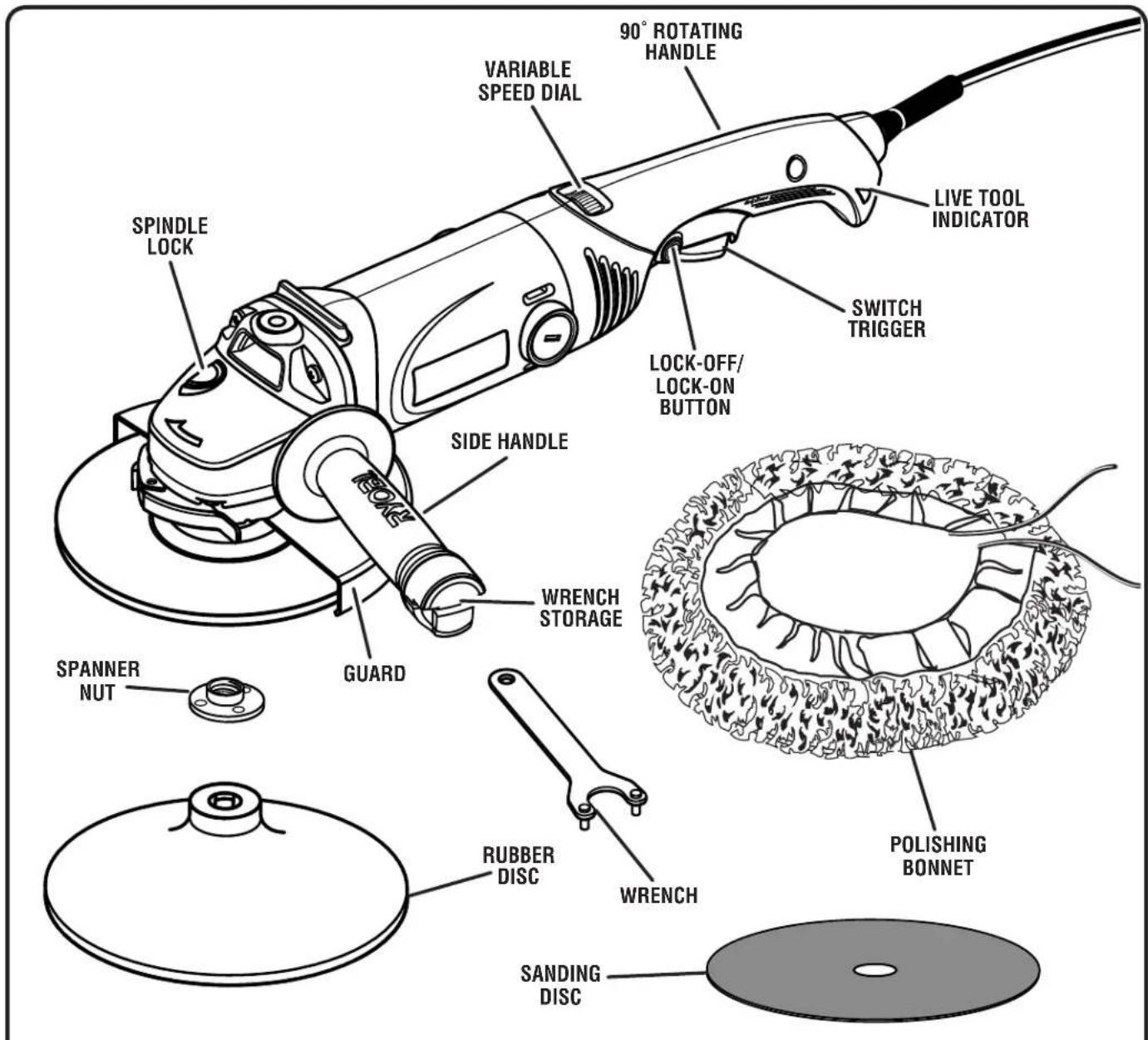
Fig. 1
FEATURES
KNOW YOUR MULTI-PURPOSE GRINDER
See Figure 1.
The safe use of this product requires an understanding of the information on the product and in this operator's manual as well as a knowledge of the project you are attempting. Before use of this product, familiarize yourself with all operating features and safety rules.
90° ROTATING HANDLE
The handle rotates 90° to the left or right for ease of use.
LIVE TOOL INDICATOR
The live tool indicator is located on the handle of the grinder and indicates that the tool is connected to a power supply.
LOCK-OFF/LOCK-ON BUTTON
The lock-off/lock-on button serves both to unlock the switch trigger and to allow the switch trigger to be locked on.
SIDE HANDLE
The side handle can be installed on the top, left, or right side of the tool, depending on operator preference, for stabilization and must be used during all operations. In addition to maintaining safe control during use, the side handle also provides convenient ease of operation for the operator.
SPINDLE LOCK
The spindle lock keeps the spindle from turning while installing and removing wheels and discs.
SWITCH TRIGGER
The tool has a conveniently located switch trigger.
TOOLLESS GUARD
A toolless protective guard deflects sparks and metal chips during grinder use.
VARIABLE SPEED DIAL
The variable speed dial enables the tool to operate faster or slower, depending on the selected speed.
WRENCH STORAGE
The wrench can be easily stored in the side handle when not in use.
ASSEMBLY
UNPACKING
This product requires assembly.
- Carefully remove the product and any accessories from the box. Make sure that all items listed in the packing list are included.
■ Inspect the product carefully to make sure no breakage or damage occurred during shipping.
■ Do not discard the packing material until you have carefully inspected and satisfactorily operated the product.
■ If any parts are damaged or missing, please call 1-800-525-2579 for assistance.
PACKING LIST
Multi-Purpose Grinder
Side Handle
Wrench
Rubber Disc
Sanding Disc
Spanner Nut
Polishing Bonnet
Tool Bag
Operator's Manual

WARNING:
If any parts are damaged or missing do not operate this product until the parts are replaced. Failure to heed this warning could result in serious personal injury.

WARNING:
Do not attempt to modify this product or create accessories not recommended for use with this product. Any such alteration or modification is misuse and could result in a hazardous condition leading to possible serious personal injury.

WARNING:
Do not connect to power supply until assembly is complete. Failure to comply could result in accidental starting and possible serious personal injury.
ASSEMBLY

WARNING:
The side handle must always be used to help prevent loss of control and possible serious injury.
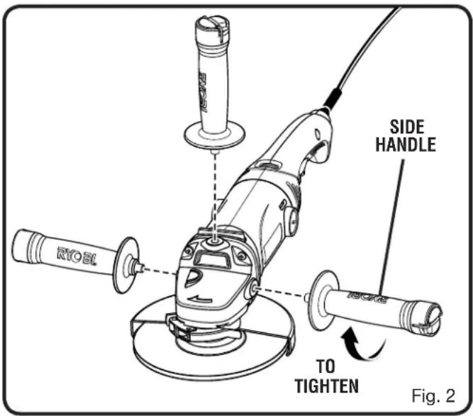
INSTALLING THE SIDE HANDLE
See Figure 2.
■ Unplug the tool.
- Insert the side handle into the desired operating position.
- Securely tighten by turning the side handle clockwise.
NOTE: The handle can be installed on the top, left, or right side of the tool, depending on operator preference.
OPERATION

WARNING:
Do not allow familiarity with this product to make you careless. Remember that a careless fraction of a second is sufficient to inflict serious injury.

WARNING:
Always wear safety goggles or safety glasses with side shields when operating power tools. Failure to do so could result in objects being thrown into your eyes resulting in possible serious injury.

WARNING:
Do not use any attachments or accessories not recommended by the manufacturer of this product. The use of attachments or accessories not recommended can result in serious personal injury.
APPLICATIONS
You may use this product for the purposes listed below:
■ Grinding metals
■ Sanding wood or metal surfaces
■ Polishing and buffing
SWITCH TRIGGER
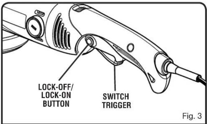
See Figure 3.
To turn the tool ON, depress the lock-off/lock-on button, then depress the switch trigger. To turn it OFF, release the switch trigger.
OPERATION
LOCK-OFF/LOCK-ON BUTTON
See Figure 3.
The lock-off/lock-on button prevents accidental starting of the grinder, and also allows the grinder to be locked-on, which is convenient for continuous grinding/sanding/polishing for extended periods of time.
To lock-on:
■ Push in and hold the lock-off/lock-on button, located on the side of the handle.
■ Depress the switch trigger.
■ Push in further on the lock-off/lock-on button.
■ Release the switch trigger.
■ Release the lock-on button and the tool will continue running.
■ To release the lock, depress and release the switch trigger.
If the lock-on feature is engaged during use and the tool becomes disconnected from the power supply, disengage the lock-on feature immediately.
CAUTION:
Never cover air vents. They must always be open for proper motor cooling.
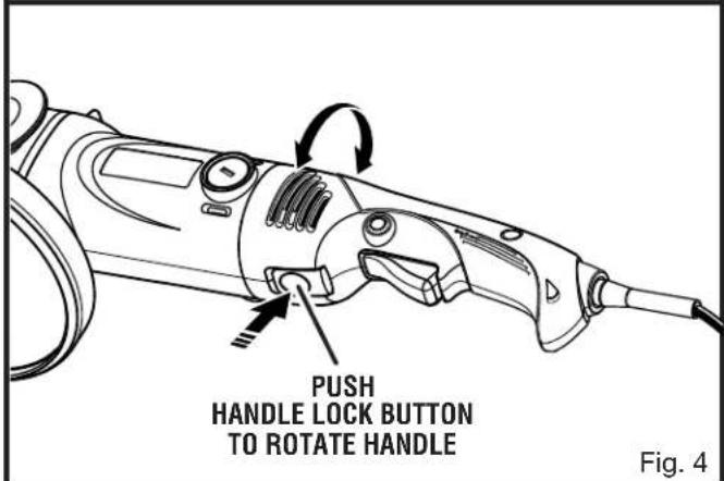
90° ROTATING HANDLE
See Figure 4.
The handle on the tool can rotate 90° to the left or right for ease of operation.
To adjust the handle:
■ Unplug the tool.
■ Press and hold handle lock button.
■ Rotate the handle to the desired position and release the handle lock button.

WARNING:
Make sure the handle lock button on the handle clicks and locks into place when changing handle positions. Failure to heed this warning could result in serious personal injury.
VARIABLE SPEED DIAL
See Figure 5.
The variable speed dial allows you to optimize the speed of the tool based on the desired application. Refer to the chart at right for proper speed selection.
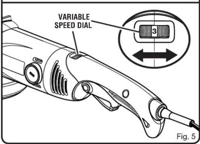
| APPLICATION SPEED SETTING | |
| Polishing | 1-2 |
| Sanding | 3-5 |
| Grinding | 6 |
OPERATION

WARNING:
Before performing any adjustment, make sure the tool is unplugged from the power supply and the switch is in the OFF position. Failure to heed this warning could result in serious personal injury.
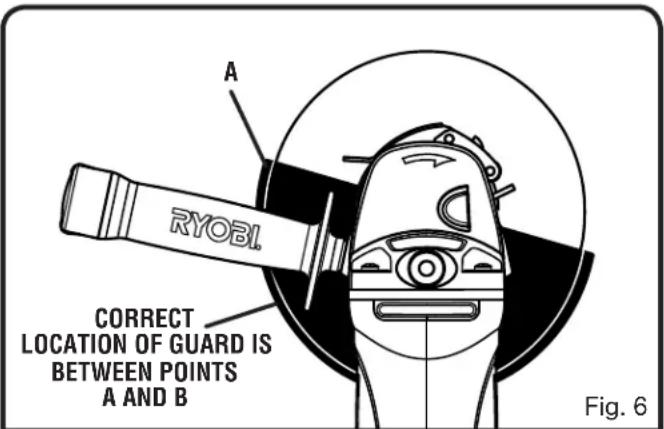
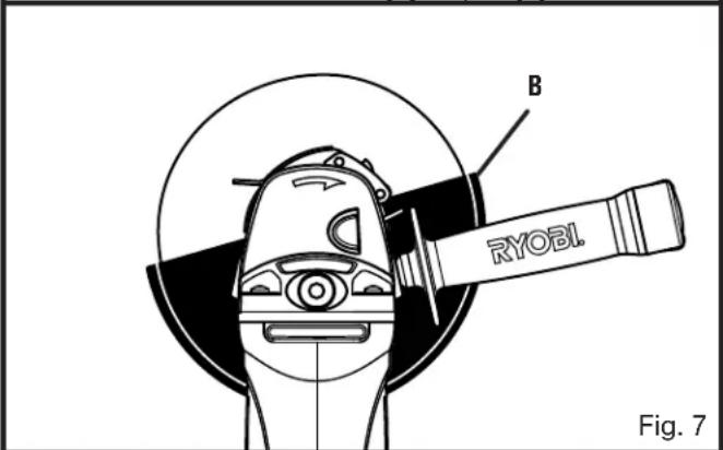
GUARD ADJUSTMENT
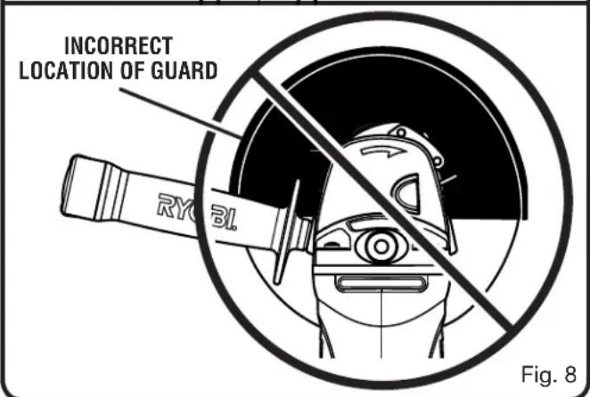
See Figure 6 - 8.
Never use the tool for grinding without the guard in place and properly adjusted.
■ Unplug the tool.
■ Using the wrench provided, remove clamp nut, grinding wheel, and disc flange, if necessary.
■ Unlock the guard clamp lever.
■ Rotate the guard to its correct position as shown in figures 6 and 7.
■ Lock the guard clamp lever.
■ Reassemble disc flange, grinding wheel, and clamp nut (if removed) and tighten securely.

WARNING:
Never place the guard so that it is on front of the grinder as shown in figure 8. This could result in serious injury because sparks and loose particles thrown from the grinding wheel would be directed toward the operator. Always place the guard in the correct location as shown in figures 6 and 7.

DANGER:
Never use your grinder with the guard removed. It has been designed for use only with the guard installed. Attempting to use grinder with guard removed will result in loose particles being thrown against the operator resulting in serious personal injury.
GRINDING
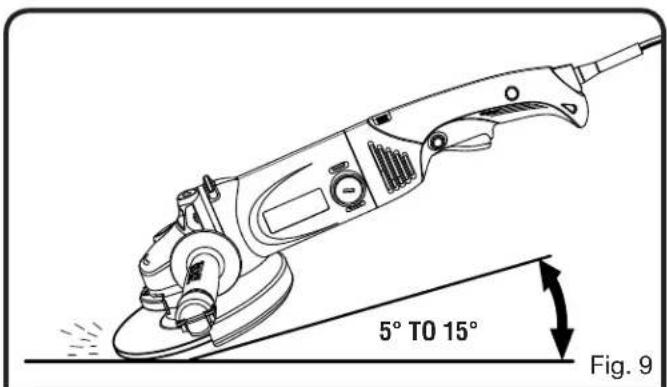
See Figure 9.
Always carefully select and use grinding wheels that are recommended for the material to be ground. Make sure that the minimum operating speed of any accessory wheel selected is 6,800 r/min. or more. The grinding wheel provided with the grinder is suitable for grinding welds, preparing surfaces to be welded, grinding structural steel, and grinding stainless steel.
To operate the grinder:
- Secure all work in a vise or clamp to a workbench.
■ Hold the grinder in front and away from you with both hands, keeping the grinding wheel clear of the workpiece.
■ Turn on the grinder and let the motor and grinding wheel build up to full speed.
■ Lower the grinder gradually until the grinding wheel contacts the workpiece.
- Keep the grinder tilted at an angle from 5 to 15 degrees.
OPERATION

WARNING:
To prevent loss of control and possible serious personal injury, always operate the grinder with both hands, keeping one hand on the side handle.
■ Move the grinder continuously at a steady, consistent pace.
CAUTION:
If the grinder is held in one spot too long, it will gouge and cut grooves in the workpiece. If the grinder is held at too sharp an angle, it will also gouge the workpiece because of concentration of pressure on a small area.
■ Use just enough pressure to keep the grinder from chattering or bouncing.
NOTE: Heavy pressure will decrease the grinder's speed and put a strain on the motor. Normally the weight of the tool alone is adequate for most grinding jobs. Use light pressure when grinding jagged edges or loose bolts where there is the potential for the grinder to snag on the metal edge.
■ Lift the grinder away from the workpiece before turning off.
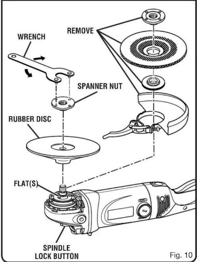
INSTALLING RUBBER DISC
See Figure 10.
The grinding wheel and guard must be removed and the rubber disc installed to use the tool for sanding or polishing.
To install the rubber disc:
■ Unplug the tool.
■ Depress and hold spindle lock button and rotate clamp nut with provided wrench until spindle locks.
NOTE: To prevent damage to the spindle or spindle lock, always allow motor to come to a complete stop before engaging spindle lock.
■ Loosen and remove clamp nut from spindle.
■ Remove grinding wheel, disc flange, and guard.
■ Install rubber disc. Make sure flats on the bottom of disc flange are engaged with flats on spindle.
■ Install spanner nut on spindle with the flange side of the nut facing the rubber disc. Finger tighten.
■ Depress and hold the spindle lock button and rotate the wheel clockwise until the spindle locks in position.
- Securely tighten the spanner nut with the wrench provided. Do not overtighten.
■ To reinstall the grinding wheel after sanding or polishing, see Replacing Grinding Wheel and Replacing Guard in the Maintenance section of this manual.
OPERATION
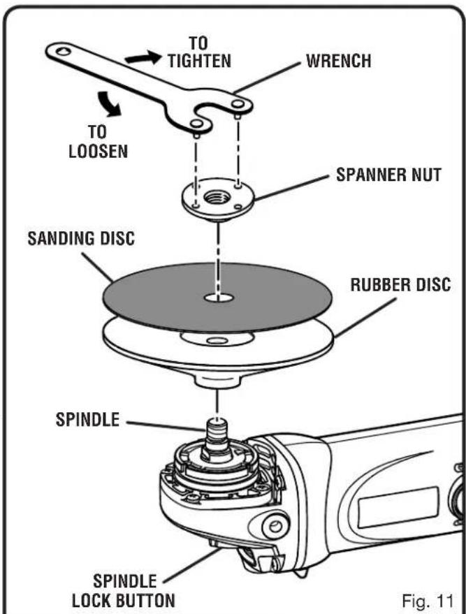
INSTALLING SANDING DISC
See Figure 11.
Before installing the sanding disc, the rubber disc must be installed on the tool. If the grinding wheel and guard are on the tool, they must be removed first. Follow the steps in Installing Rubber Disc before proceeding.
■ Unplug the tool.
■ Depress and hold spindle lock button and rotate spanner nut with provided wrench until spindle locks.
NOTE: To prevent damage to the spindle or spindle lock, always allow motor to come to a complete stop before engaging spindle lock.
■ Loosen and remove spanner nut from spindle.
■ Center and place the sanding disc over the rubber disc.
■ Install spanner nut on spindle. Finger tighten.
■ Depress and hold the spindle lock button and rotate the wheel clockwise until the spindle locks in position.
- Securely tighten the spanner nut with the wrench provided. Do not overtighten.

WARNING:
To prevent loss of control and possible serious personal injury, always operate the tool with both hands, keeping one hand on the side handle.
SANDING
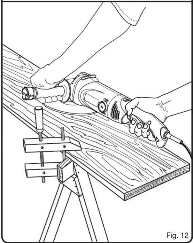
See Figure 12.
Clamp or otherwise secure the work to prevent it from moving under the tool. Secure small workpieces in a vise or use clamps to secure them to a workbench.

WARNING:
Unsecured work could be thrown towards the operator causing injury.
Hold the tool in front and away from you, keeping it clear of the workpiece. Start the tool by depressing the switch trigger and letting the motor build to its maximum speed. Gradually lower sander to the workpiece at a slight (5° to 8°) angle.
Do not attempt to hold the sanding disc flat on the workpiece. Always keep the tool in motion moving over the work, allowing it to operate freely without unnecessary pressure. The weight of the unit supplies adequate pressure, so let the sanding disc and sander do the work. Applying additional pressure only slows the motor, rapidly wears sanding discs, damages rubber disc, and greatly reduces sander speed.
Excessive pressure will overload the motor, causing possible damage from motor overheating, which can result in inferior work. Any finish or resin on wood may soften from the frictional heat.
OPERATION
Do not sand too long in one spot. This will cause uneven sanding and gouging of the work.
Upon completion of a sanding operation, lift tool away from work surface before turning off.

WARNING:
Sanding disc must come to a complete stop before setting tool down on workbench. Failure to do so can cause the tool to be thrown from workbench because of sanding disc rotation. This could result in damage to the tool or possible serious injury to the operator.
SANDING DISC SELECTION
Selecting the correct size grit and type sanding disc is an extremely important step in achieving a high quality sanded finish. Aluminum oxide, silicon carbide, and other synthetic abrasives are best for power sanding. Natural abrasives, such as flint and garnet are too soft for economical use in power sanding.
In general, coarse grit will remove the most material and finer grit will produce the best finish in all sanding operations.
The condition of the surface to be sanded will determine which grit will do the job. If the surface is rough, start with a coarse grit and sand until the surface is uniform.
Medium grit may then be used to remove scratches left by the coarser grit and finer grit used for finishing the surface.
Always use the proper grit sanding disc, and not extra pressure when sanding. Continue sanding with each grit until surface is uniform.
INSTALLING/REMOVING POLISHING BONNET
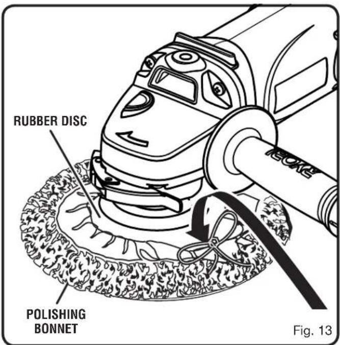
See Figure 13.
Before installing the polishing bonnet, the rubber disc must be installed on the tool. If the grinding wheel and guard are on the tool, they must be removed first. Follow the steps in Installing Rubber Disc before proceeding.
■ Unplug the tool.
■ Remove sanding disc, if necessary.
■ Securely retighten spanner nut with the wrench provided, if necessary.
■ Slip polishing bonnet over rubber disc.
■ Pull string ends tight and tie in a bow to secure bonnet.
■ Tuck string ends and bow underneath bonnet.

WARNING:
Failure to tuck string ends and bow underneath bonnet could result in string ends coming loose and hitting or grabbing foreign objects.
■ To remove, untie string and pull polishing bonnet edges over and off rubber disc.
■ To reinstall the grinding wheel after sanding or polishing, see Replacing Grinding Wheel and Replacing Guard in the Maintenance section of this manual.
OPERATION
POLISHING
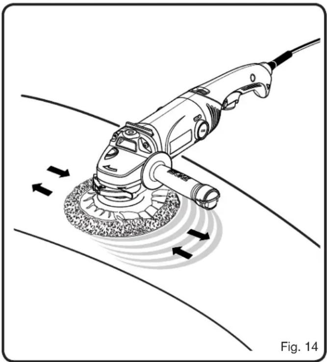
See Figure 14.

WARNING:
Keep a firm grip on the tool with both hands at all times. Failure to do so could result in loss of control leading to possible serious injury.
When polishing, hold the tool firmly, allowing it to operate freely without unnecessary pressure. The weight of the tool alone will provide adequate pressure for polishing at top efficiency. For best results, always operate at low speed when polishing.
Bonnets must be kept clean and free from grit, dirt, and other abrasive particles. When bonnets become dirty and clogged with polishing film, wash in lukewarm water with a mild detergent. Allow bonnets to dry thoroughly before reuse. Polish with a long sweeping motion, back and forth, advancing along the surface to be polished. Do not hold the tool in one spot or use a circular or spiral pattern. This will cause swirls in the finish.
Spread a light coat of polish or wax over a small area. Polish with the tool according to the manufacturer's instructions printed on the label of the polish or wax container.
NOTE: Some polishes should be buffed while damp while others must be allowed to dry; therefore, always check the manufacturer's label.
Tilt the tool so that the polishing bonnet is at a slight angle to the work surface. Always start polishing at the top or highest point and work down. This will prevent light dust or polish film from being thrown upon completed section. It also eliminates pulling the tool's power cord over sections already polished.
Surfaces that have an old film of wax or polish, or that have not been polished or waxed for an extended period of time, may require a second application. This is especially true on oxidized surfaces. Heavily oxidized surfaces should be cleaned with a commercial paste or liquid cleaner before polishing or waxing.

WARNING:
Check polishing bonnets before each use. Make sure they are clean and free from any loose particles or foreign objects that may be embedded in the bonnet. Failure to do so could cause these particles or objects to be thrown from the tool resulting in possible serious injury.
MAINTENANCE

WARNING:
When servicing, use only identical replacement parts. Use of any other parts may create a hazard or cause product damage.

WARNING:
Always wear safety goggles or safety glasses with side shields during power tool operation or when blowing dust. If operation is dusty, also wear a dust mask.
GENERAL MAINTENANCE
Avoid using solvents when cleaning plastic parts. Most plastics are susceptible to damage from various types of commercial solvents and may be damaged by their use. Use clean cloths to remove dirt, dust, oil, grease, etc.

WARNING:
Do not at any time let brake fluids, gasoline, petroleum-based products, penetrating oils, etc., come in contact with plastic parts. Chemicals can damage, weaken or destroy plastic which may result in serious personal injury.
Electric tools used on fiberglass material, wallboard, spackling compounds, or plaster are subject to accelerated wear and possible premature failure because the fiberglass chips and grindings are highly abrasive to bearings, brushes, commutators, etc. Consequently, we do not recommend using this tool for extended work on these types of materials. However, if you do work with any of these materials, it is extremely important to clean the tool using compressed air.
LUBRICATION
All of the bearings in this product are lubricated with a sufficient amount of high grade lubricant for the life of the unit under normal operating conditions. Therefore, no further lubrication is required.
POWER SUPPLY CORD REPLACEMENT
If replacement of the power supply cord is necessary, this has to be done by an authorized service center in order to avoid a safety hazard.

WARNING:
To prevent accidental starting that could cause possible serious personal injury, turn off and unplug the tool before performing any maintenance or adjustment.
REPLACING GRINDING WHEEL
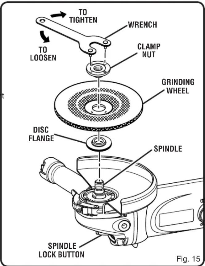
See Figure 15.

WARNING:
Thoroughly inspect a new grinding wheel before you install it on the grinder.
- Tap lightly around the wheel using a wooden hammer.
- Listen carefully to the resulting sounds. Places with fissures or cracks will result in a different sound.
Do not use a wheel containing fissures or cracks.
When you install a new grinding wheel, carry out a no load revolution test of approximately one minute with the grinding wheel facing a safe direction, i.e., away from people or objects.
■ Unplug the tool.
■ Depress the spindle lock button and rotate the clamp nut until the spindle locks.
NOTE: To prevent damage to the spindle or spindle lock, always allow motor to come to a complete stop before engaging spindle lock.
■ Loosen and remove the clamp nut from the spindle. Do not remove the disc flange.
MAINTENANCE
■ Make sure the flats on the bottom of the disc flange are engaged with the flats on the spindle.
■ Place the grinding wheel over the spindle.
■ Thread the clamp nut on the spindle with the flat side of the nut facing up.

WARNING:
Always install a grinding wheel with the depressed centre against the disc flange. Failure to do so will cause the grinding wheel to crack when tightening the clamp nut. This could result in serious personal injury because of loose particles breaking off and being thrown from the grinder. Do not overtighten.
■ Depress the spindle lock button and rotate the wheel clockwise until the spindle locks in position.
■ Tighten the clamp nut securely with the wrench provided. Do not overtighten.

DANGER:
Never attach a wood cutting or carving blade of any type to this grinder. It is only designed for grinding. Use for any other purpose is not recommended and creates a hazard, which will result in serious injury.

DANGER:
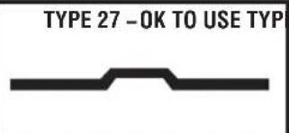
Use ONLY Type 27 depressed center wheels (such as the one provided with this product). NEVER attach a Type 1 straight or cut-off wheel to this angle grinder. This product is only designed for grinding and sanding. Use for any other purpose is not recommended and creates a hazard, which will result in serious injury.

REPLACING GUARD
See Figure 16.
■ Unplug the tool.
■ Depress spindle lock button and rotate nut with provided wrench until spindle locks.
NOTE: To prevent damage to the spindle or spindle lock, always allow motor to come to a complete stop before engaging spindle lock.
■ Using the wrench provided, loosen and remove nut, grinding wheel or rubber disc, and disc flange, if necessary, from spindle.
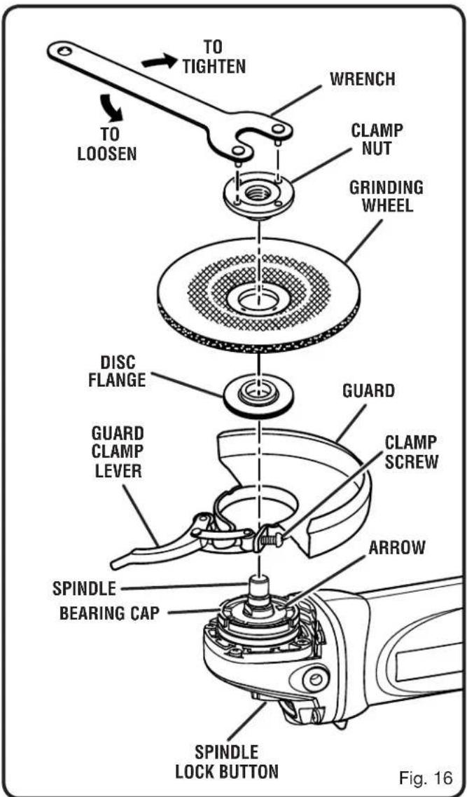
■ Unlock the guard clamp lever and remove old guard, if necessary.
■ Remove the guard.
■ Place the new guard on the shoulder of the bearing cap, aligning the arrow on the bearing cap with the notch on the guard.
NOTE: If the new guard will not fit, loosen the clamp screw until it will slide over the bearing cap. Be sure the tabs on the guard are seated in the groove in the bearing cap.
■ Rotate guard to the correct position as shown in figures 6 and 7 on page 14.
■ Lock the guard clamp lever.
■ Tighten clamp nut securely if needed.
MAINTENANCE
REPLACING BRUSHES
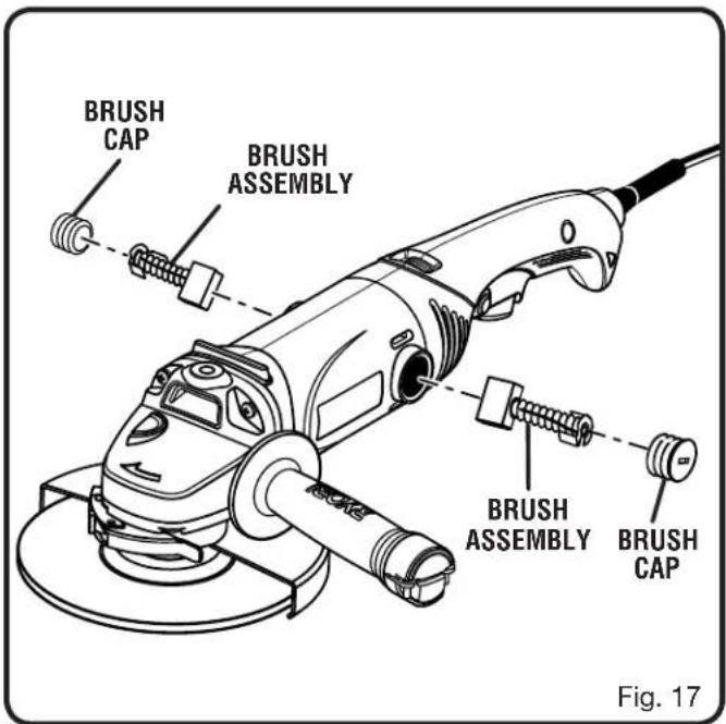
See Figure 17.
This product has externally accessible brush assemblies that should be periodically checked for wear.
■ Unplug the tool.
■ With a flat head screwdriver, remove the brush caps. The brush assembly is spring loaded and will pop out when you remove the brush cap.
■ Remove the brush assembly (brush and spring). Check for wear. Replace both brushes when either has less than 1/4 in. length of carbon remaining. Do not replace one side without replacing the other.
■ Reassemble using new brush assemblies. Make sure curvature of brush matches curvature of motor and that brush moves freely in brush tube.
■ Replace brush cap and tighten securely. Do not over-tighten.
OPERATOR'S MANUAL
7 in. MULTI-PURPOSE GRINDER DOUBLE INSULATED
AG700

WARNING:
Some dust created by power sanding, sawing, grinding, drilling, and other construction activities contains chemicals known to cause cancer, birth defects or other reproductive harm. Some examples of these chemicals are:
- lead from lead-based paints,
- crystalline silica from bricks and cement and other masonry products, and
• arsenic and chromium from chemically-treated lumber.
Your risk from these exposures varies, depending on how often you do this type of work. To reduce your exposure to these chemicals: work in a well ventilated area, and work with approved safety equipment, such as those dust masks that are specially designed to filter out microscopic particles.
• PARTS AND SERVICE
Prior to requesting service or purchasing replacement parts, please obtain your model and serial number from the product data plate.
- MODEL NUMBER
AG700
- SERIAL NUMBER
• HOW TO OBTAIN REPLACEMENT PARTS:
Replacement parts can be purchased online at www.ryobitools.com or by calling 1-800-525-2579. Replacement parts can also be obtained at one of our Authorized Service Centers.
• HOW TO LOCATE AN AUTHORIZED SERVICE CENTER:
Authorized Service Centers can be located online at www.ryobitools.com or by calling 1-800-525-2579.
• HOW TO OBTAIN CUSTOMER OR TECHNICAL SUPPORT:
To obtain Customer or Technical Support please contact us at 1-800-525-2579.
RYOBI® is a registered trademark of Ryobi Limited used under license.





- 7 IN. MULTI-PURPOSE GRINDER DOUBLE INSULATED
- TABLE OF CONTENTS
- INTRODUCTION
- WARRANTY
- RYOBI® POWER TOOL - LIMITED TWO YEAR WARRANTY AND 30 DAY EXCHANGE POLICY
- GENERAL SAFETY RULES
- WARNING
- SAVE THESE INSTRUCTIONS
- WORK AREA SAFETY
- ELECTRICAL SAFETY
- PERSONAL SAFETY
- POWER TOOL USE AND CARE
- SERVICE
- SPECIFIC SAFETY RULES
- SAFETY WARNINGS COMMON FOR GRINDING, SANDING AND POLISHING OPERATIONS
- KICKBACK AND RELATED WARNINGS
- SAFETY WARNINGS SPECIFIC FOR GRINDING OPERATIONS
- SAFETY WARNINGS SPECIFIC FOR SANDING OPERATIONS
- SAFETY WARNINGS SPECIFIC FOR POLISHING OPERATIONS
- ADDITIONAL SAFETY RULES
- SYMBOLS
- ELECTRICAL
- DOUBLE INSULATION
- ELECTRICAL CONNECTION
- EXTENSION CORDS
- FEATURES
- PRODUCT SPECIFICATIONS
- KNOW YOUR MULTI-PURPOSE GRINDER
- 90° ROTATING HANDLE
- LIVE TOOL INDICATOR
- LOCK-OFF/LOCK-ON BUTTON
- SIDE HANDLE
- SPINDLE LOCK
- SWITCH TRIGGER
- TOOLLESS GUARD
- VARIABLE SPEED DIAL
- WRENCH STORAGE
- ASSEMBLY
- UNPACKING
- PACKING LIST
- INSTALLING THE SIDE HANDLE
- SEE FIGURE 2
- OPERATION
- APPLICATIONS
- TO LOCK-ON
- CAUTION
- TO ADJUST THE HANDLE
- GUARD ADJUSTMENT
- DANGER
- GRINDING
- TO OPERATE THE GRINDER
- INSTALLING RUBBER DISC
- TO INSTALL THE RUBBER DISC
- INSTALLING SANDING DISC
- SANDING
- SANDING DISC SELECTION
- INSTALLING/REMOVING POLISHING BONNET
- POLISHING
- MAINTENANCE
- GENERAL MAINTENANCE
- LUBRICATION
- POWER SUPPLY CORD REPLACEMENT
- REPLACING GRINDING WHEEL
- REPLACING GUARD
- REPLACING BRUSHES
- OPERATOR'S MANUAL
- AG700
- PARTS AND SERVICE
- HOW TO OBTAIN REPLACEMENT PARTS
- HOW TO LOCATE AN AUTHORIZED SERVICE CENTER
- HOW TO OBTAIN CUSTOMER OR TECHNICAL SUPPORT
Brand : RYOBI
Model : AG700
Category : Angle Grinder