
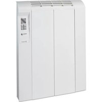
REIN-652I - Heating FAGOR - Free user manual and instructions
Find the device manual for free REIN-652I FAGOR in PDF.


| Product Type | Electric Convector Heater |
| Brand | Fagor |
| Model | REIN-652I |
| Power Source | 220-240 V, 50/60 Hz |
| Heating Power | 2000 W |
| Dimensions (W x H x D) | 65 x 45 x 12 cm |
| Weight | 6.5 kg |
| Control Type | Electronic thermostat with digital display |
| Heating Levels | 2 power settings + fan |
| Safety Features | Overheat protection, tip-over switch, child lock |
| Installation | Wall-mounted or free-standing |
| Cleaning | Wipe with damp cloth; do not use abrasive cleaners |
| Maintenance | Check power cord periodically; replace if damaged |
| Spare Parts Availability | Service center for original parts |
| Energy Class | A++ |
| Noise Level | < 40 dB |
| Fan Option | Cool fan without heating |
| Auto Shut-Off | 24-hour timer |
| Room Coverage | Up to 25 m² |
| Certification | CE, RoHS |
Frequently Asked Questions - REIN-652I FAGOR
User questions about REIN-652I FAGOR
0 question about this device. Answer the ones you know or ask your own.
Ask a new question about this device
Download the instructions for your Heating in PDF format for free! Find your manual REIN-652I - FAGOR and take your electronic device back in hand. On this page are published all the documents necessary for the use of your device. REIN-652I by FAGOR.
USER MANUAL REIN-652I FAGOR
- Important warnings 18
- Installation 18
- Use of the appliance 24
- Maintenance and cleaning of the appliance 29
- Troubleshooting 30
PORTUGUÊS
natural_image
Pure schematic diagram of a mechanical or architectural component with no text, numbers, or symbolsNOTA ECOLÓGICA
natural_image
Diagram of a server rack with ventilation slots and cable, showing directional arrows (no text or symbols)-interruptor ON / OFF
FAGOR

Cod: 970010020 Serie:050200030

09530100171411010034
(2)
natural_image
Top-down architectural floor plan showing room layout with furniture and lighting fixtures (no text or labels)
natural_image
Simple line drawing of a room with a black X mark and window, no text or symbols present
natural_image
Diagram of a elevator shaft with upward arrows indicating motion or force, mounted on a wall (no text or symbols)
IMPORTANTE
natural_image
Technical line drawing of a mechanical device with a pin and lever assembly (no text or symbols)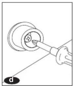
natural_image
Diagram of a hand holding a tool interacting with a circular component, labeled 'd' at the bottom (no text or symbols on the diagram itself)
natural_image
Pure technical line drawing of a mechanical component without any text, numbers, or symbols
natural_image
Diagram of a server rack with two hanging devices and connecting cables (no text or symbols)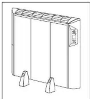
natural_image
Line drawing of a rectangular industrial device with three vertical supports and a labeled panel (no text or symbols on the device itself)natural_image
Technical line drawing of a rectangular electronic component with three vertical slots and mounting holes (no text or symbols)
natural_image
Diagram of three identical mechanical components with downward arrows indicating force or movement (no text or symbols)natural_image
Line drawing of a cabinet with a wall-mounted fan and a small electrical outlet (no text or symbols)
natural_image
Line drawing of a hand interacting with a wall-mounted air conditioner unit (no text or symbols)IMPORTANTE
natural_image
Diagram of a door with heat and airflow arrows indicating airflow direction (no text or symbols)
natural_image
Illustration of a smokestack emitting exhaust from a chimney with a crossed-out X symbol (no text or labels)IMPORTANTE
natural_image
Illustration of a hand cleaning a wall-mounted electrical outlet with an electrical plug (no text or symbols)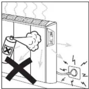

natural_image
Pure technical diagram of a mechanical component with two arrows indicating direction (no text or symbols)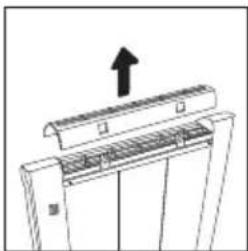
natural_image
Diagram of a mechanical assembly with an upward arrow indicating motion (no text or symbols present)
natural_image
Simple line drawing of a faucet spraying water onto a horizontal surface (no text or symbols)Es aconsejable
Fagor responds to lack of conformity that may occur within the first two years after the delivery, as set out in the Law 23/2003.
The solution of any problems that may appear within the first six months after the date of purchase will be free of charge for the user.
Fagor also offers a guarantee of up to two years for the parts and components of the appliance, only if they are replaced by Fagor's Offi cial Technical Support Service.
GUARANTEE EXCLUSIONS
The following are not covered by this Guarantee, and in such cases the total repair costs will therefore correspond to the user;
a) Breakdown caused by the consumer's negligence or misuse of the appliance
b) Breakdown caused by unforeseeable circumstances, force majeure (weather conditions or geological phenomena) and accidents.
c) Breakdown or damage deriving from incorrect or illegal installation, or installation with a power supply other than that indicated.
d) This appliance is for domestic use only. The guarantee does not cover its use in industrial or commercial establishments.
e) Any damages caused to the user as a result of the appliance's failure to function due to breakdown.
ANNULMENT OF THE GUARANTEE
This Guarantee shall be null and void if the appliance has been manipulated, modified or repaired by unauthorised persons or technical services other than the brand's official technical assistance services.
VERY IMPORTANT: TO BENEFIT FROM THIS GUARANTEE, IT IS ABSOLUTELY ESSENTIAL FOR THE USER TO PROVIDE PROOF OF DATE OF PURCHASE TO THE GUARANTOR'S AUTHORISED TECHNICAL SERVICE, BY SHOWING THEM THE OFFICIAL RECEIPT FOR THE APPLIANCE. IN THE CASE OF APPLIANCES SUPPLIED IN NEW CONSTRUCTIONS, SUFFICIENT PROOF OF THE DATE OF THE APPLIANCE'S AVAILABILITY FOR USE MUST BE PROVIDED.
This Guarantee shall only be valid in the European Union, and it shall only cover the appliance mentioned, supplied by Fagor Electrodomésticos, S.Coop. B° San Andrés n° 18, 20500 Mondragón-Guipúzcoa. For other countries, please consult your distributor.
ECO-HEATER
0
IMPORTANT WARNINGS
- This appliance is not designed for use by physically, sensorially or mentally handicapped people (including children), or people without experience or knowledge of the appliance, unless they are supervised or instructed in its use by a person responsible for their safety. Children must be supervised to ensure they do not play with the appliance.
- Read these instructions carefully and keep them for future reference.
- Do not install the appliance under an electrical socket.
- In bathrooms, the appliance must be installed in accordance with national law concerning electrical installations.
- Do not handle the appliance with wet hands.
- Never pull on the cable to remove the plug.
- If the connection cable should be damaged, it must be replaced by qualified personnel.
- Do not cover the appliance, or place it near fl ammable materials.
- Do not cover the air inlet or outlet when the appliance is operating.
- The eco-emitter's surfaces may become hot. Small children must be supervised when they are close to it.
- In case of malfunctioning, consult an Authorised Technical Service.

INSTALLATION
1 UNPACKING THE APPLIANCE
Unpack the appliance and remove the polystyrene protectors.
When handling the appliance to fix it to the wall, pick it up by its sides and not by the front grille, to prevent possible damage.
The characteristics label is on the rear of the Eco-heater. This label must not be removed under any circumstances, as it informs of the exact model of Eco-heater and its serial n°, and provides electrical data on the appliance.

natural_image
Pure schematic diagram of a mechanical or architectural component with no text, numbers, or symbolsECO-NOTE
This appliance has been designed and manufactured with total respect for the environment. Ensure the packaging of your appliance is correctly disposed of.

natural_image
Diagram of a device rear panel with cable and directional arrows indicating ports (no text or symbols)
[2]
Location of your home
In order to make the most of the Eco-heater's energy savings, you should take the location of your home into account. Aspects such as the climatic zone, the orientation of the home and the type of insulation are vital in determining the most suitable range of appliances.
Size of the home
Another factor to be taken into account is the total surface area of the home and how it is divided into the different rooms. To help you make this calculation, there is an online application at www.fagor.com, or you may consult your distributor.
After making this previous analysis, locate the Eco-heaters in each room of the house to obtain maximum heating comfort with minimum power consumption.
Location of the Eco-heater
Wall: Choose a wall where no furniture is to be placed. It is a good idea to place the Eco-heater centrally with respect to the wall, keeping it away from doors and windows. You should also avoid placing it next to objects such as furniture, curtains or other appliances.
Corners: Avoid placing the Ecoheater in a corner of the room.
Windows: The appliance may exceptionally be installed under a window. This solution is often used when there are no other walls free. However, you should not forget that heat may be lost through the window.

natural_image
Top-down floor plan of a room with furniture layout and ceiling lights (no text or symbols)
natural_image
Simple line drawing of a room corner with a black X mark and window, no text or symbols present
natural_image
Diagram of a cabinet with two upward arrows indicating movement or force, no text or symbols present
IMPORTANT
Do not install the Eco-heater under an electrical socket.
(3)
MOUNTING
3.1 Wall-mounting
When you have decided whereabouts in the room the eco-heater is to be installed, it should be fixed to the wall as follows:
a Position the Eco-heater in its
location, propping it up with books or the polystyrene protectors from the packaging. The minimum distances shown in the figure must be maintained. Take the following references:
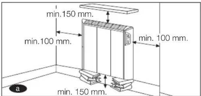
b Mark the hole positions: Take into account the distance from the fl oor (620 mm) and the distance between the fi xing parts, depending on the model.
Fixing parts: To fi x the appliance to the wall, use the two fi xing clips supplied. At the rear of the Ecoheater there are two grooves for these fi xing clips to be fitted into.

C Drill suitable holes: Insert the ∅6 mm rawl plugs supplied with the fi xing kit, position the fi xing clips and tighten the screws until the clips are sufficiently secured.
Level the clips in the elongated holes until they are at the same height, then firmly tighten the screws.

natural_image
Technical line drawing of a mechanical clamp or bracket assembly with directional arrows and a labeled component (no text or symbols present)
natural_image
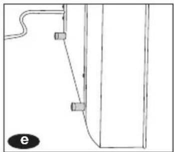
Diagram of a mechanical component with a tool inserted into a housing (no text or symbols)d/e Before fi xing the appliance to the wall, you should fi rst fi x in place two stops, which are contained in the fi xing kit. Turn the Eco-
Heater face down. On the lower rear part of the Eco-Heater there are two threaded holes for these stops to be screwed into using 2 screws ( 2.9 x 9.5). Position the stops as shown in the diagram and screw in the screws until the stops are correctly fixed to the appliance.
natural_image
Pure technical line drawing of a mechanical component or bracket (no text or symbols)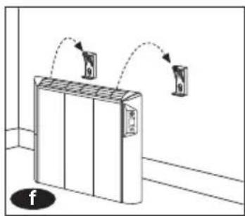
natural_image
Diagram of a server rack with two hanging devices and a base unit, no text or symbols presentf Hang the appliance from the top fi xing clips.
Check the appliance is securely fixed in place.
3.2 Floor attachment accessory INNOVATION
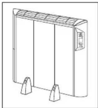
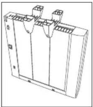
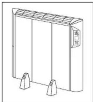
In cases where use of the wall support is not possible, support feet are available that are attached to both the device and the floor as follows:
natural_image
Line drawing of a rectangular industrial or storage unit with three vertical supports and a labeled door (no text or symbols on the main structure)a Install feet on underside of radiator, push them in fully.
natural_image
Technical line drawing of a rectangular electronic component with three vertical slots and mounting holes (no text or symbols)
natural_image
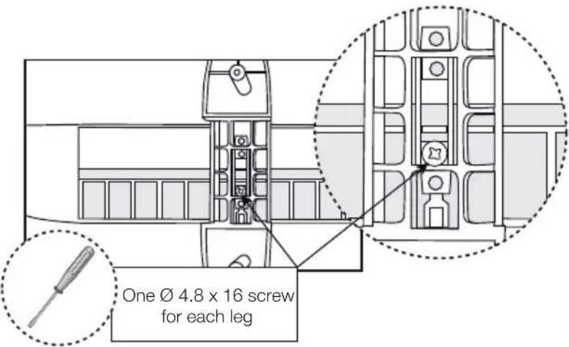
Diagram of two container-like structures with downward arrows indicating movement or force (no text or symbols)b The legs may be screwed in place. Before inserting the screws, align each leg with the vertical lines on the eco-heater, so that the holes in the leg (where the screws are to be inserted) coincide with the holes in the eco-heater. Tighten the screws until the legs are firmly fixed to the appliance.
NOTE: On 650W eco-heaters, only one leg may be screwed in to the central part of the eco-heater. It is therefore recommended to fit the legs in place without screwing them in.
C Position the radiator on the floor where appropriate, respecting minimum distances indicated in Figure 1.

d Once positioned, use a pencil or point to mark fixing points, and attach the device to the floor. Insert wall plugs and screws.
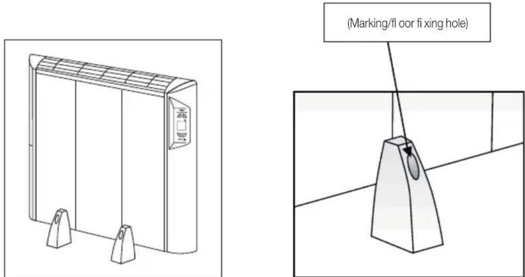
e Having attached the device, install plugs to cover holes in feet.
4 ELECTRICAL CONNECTION
A correct electrical connection must be made for the Eco-heater to function correctly. This is a simple process, but certain conditions must be taken into account.
Electrical installation in the home
The electrical installation must correspond to the voltage indicated on the appliance. It must be of the correct voltage and have a good earth connection. It must comply with all the applicable legislation and you must have the necessary power contracted with the electrical company to connect all the appliances installed.
| model | intensity |
| 636 W | 2,8 A |
| 954 W | 4,2 A |
| 1272 W | 5,5 A |
| 1590 W | 6,9 A |
Installing several appliances
The Eco-heaters may be simultaneously protected and connected by a common overload protector, but always make that the total current of the appliances does not exceed the maximum permitted.
Installing an appliance.
a The Eco-heater is supplied with a power cable and Schuko plug.
b Installing a socket: If a new socket needs to be installed, it is recommended that the centre of the socket is located approximately 100 mm to the right of the appliance, and 100 mm above the bottom of the appliance.
C Press the On/Off master switch for the electrical current: This is on the rear of the appliance.


natural_image
Line drawing of a cabinet with a wall-mounted power outlet and a small electrical outlet (no text or symbols)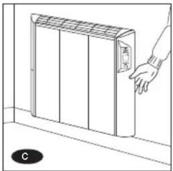
natural_image
Line drawing of a hand interacting with a wall-mounted air conditioner unit (no text or symbols)IMPORTANT
The power cable must not touch the hot parts of the radiator.
If the connection cable of the appliance should be damaged, in order to prevent hazard it must be replaced by a service authorised by the manufacturer.
The socket must never be located either behind or above the Eco-heater.
5 TECHNICAL CHARACTERISTICS
| MODELS | ||||
| 636 W | 954 W | 1272 W | 1590 W | |
CHARACTERISTICS
| Power (W) 636 954 1272 1590 | |||||
| Component number 4 6 8 10 | |||||
| Kind I insulation • • • • | |||||
| Voltage/ Frequency (V/Hz) 230 V / 50Hz 230 V / 50Hz 230 V / 50Hz 230 V / 50Hz | |||||
| Sizes | Height | 610 | 610 | 610 | 610 |
| Width | 460 | 610 | 780 | 910 | |
| Depth | 95 | 95 | 95 | ||
95
(1) PRESENTATION
MODEL I MODEL IP
BACKLIT LCD DISPLAY
This lights up for 30 sec. when any of the buttons is pressed.

(**) The heat ON indicator appears on the display when the appliance is emitting heat. The Ecoheater itself determines when it should be switched on, via its electronic sensors, depending on the temperature of the room and smart energy use.
(2)
FUNCTIONAL CHARACTERISTICS
2.1 Switching on the appliance
To start up the Eco-heater, proceed as follows:
a Switch on the ON/OFF electrical current master switch on the rear of the Eco-heater. The red indicator light comes on to show that the appliance is in standby mode.
b Press the On/Standby button ◆ to start up the radiator. When you switch off the radiator using this button, two horizontal dashes will appear on the display “- -”
c Press the MODE button to choose between the different functioning modes: comfort mode *, economy mode for anti-frost mode and programming mode (model IP only).
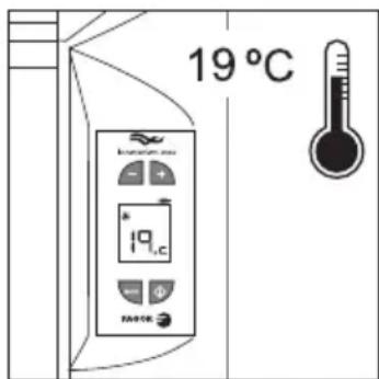
- Comfort mode: You may select the desired temperature (increasing it by 0.5°C at a time) by pressing the + and - buttons. The selection limits are 7°C and 30°C.
- Economy mode : ideal for use at night when the home is occupied, and during the daytime when the house is empty. It is automatically set at a temperature 3.5^ C lower than the setting selected for comfort mode.
- Anti-frost mode : Ideal for empty homes. The temperature is set to 7°C.
- Programming mode: the following option is for model IP only and is explained in section 3 of the manual.
C Press the + / - buttons to select the desired temperature. Only the comfort mode ✦ temperature can be selected, as the economy mode ✦ temperature is automatically set 3.5°C lower than the comfort mode temperature, and the anti-frost mode ✦ temperature is a set value.
2.1.1 Blocking the keypad
The keypad can be blocked by pressing the + and - buttons simultaneously and holding them down for 5 seconds. The message “Lo” will appear on the display. This message will then appear on the display when any button is pressed.
To unblock the keypad, press the + and - buttons again simultaneously and hold them down for 5 seconds. When the message "Lo" disappears from the screen this means the keypad has been unblocked.
2.2 Conf i guration
2.2.1 Correcting the sensor temperature measurement
The appliance has an option for adjusting and correcting the temperature. As the thermostat is located on the bottom of the appliance there may be a difference between the temperature at the sensor level and the temperature at a height of 112 metres. The sensor may also be particularly affected by draughts, which can alter its measurement.
With this option, the radiator temperature can be adjusted to the temperature of a thermometer located in any desired position.
To correct the sensor temperature, hold down the - and buttons for 5 seconds and then press the +/- buttons to change the temperature setting.
If the room temperature is lower than or the same as the temperature selected on the display and the word "ON" does not appear in the top corner of the display, you should reduce the sensor temperature until "ON" appears on the screen. The selection limits are +/- 4.5 °C. The default configuration is 0°C.
To return to the initial display, press the - and Moutons twice, although if no buttons are pressed it will automatically exit this mode after 120 seconds.
2.2.2 Display backlight time adjustment
The duration of the display backlight when a button is pressed can be adjusted. To adjust it, hold down the - and MODE buttons for 5 seconds, and then press the - and MODE buttons again. You can use the +/- buttons to adjust the time, increasing it 15 seconds at a time from 0-90 seconds. If you adjust it to 0 there will no backlight. The default configuration is 30 seconds.
To return to the initial screen press the - and Buttons again, although if no buttons are pressed it will automatically exit this mode after 120 seconds.
3 PROGRAMMING (MODEL IP ONLY)
The IP Eco-Heater offers the possibility of Individual Programming:
24 hours a day, seven days a week. The advantages of programming the appliance are:
- It can be programmed to suit your needs.
- An optimum temperature is maintained in each room of the house.
- Power optimisation and savings.
The Programming is done according to the Date and Time and the different operating modes:
Day Mode, Night Mode and Anti-Frost Mode (★, ), ★).
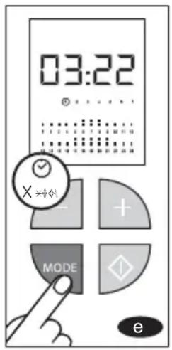
a Press the MODE button until the programming indicator (time scale) appears on the display. The Eco-heater is now in Programming mode.
The Eco-Heater comes with its own programming set by default. To change this programming, follow the instructions given below. Firstly, after it has been switched off, the date and time will need to be set on the appliance's internal clock.

Setting the Date and Time
a Hold down the MODE button for 5 seconds. The time on the internal clock will appear on the display.
b The days of the week (represented by numbers from 1 to 7) appear on the middle of the display.
C Press the + and - buttons to move forwards or backwards until the clock shows the correct time. If you hold the button down it will scan through the times faster. When the 24-hour cycle is complete it will then run through the days of the week: ▶ 2 (Tuesday) will appear, and so on until it reaches ▶ (Sunday).
On programming an Eco-Heater you should take into account the room conditions and the operating mode (★, □), if you wish to set for the seven days of the week.
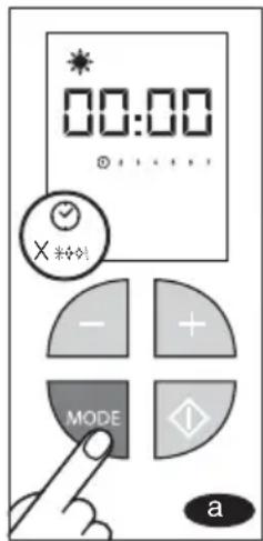

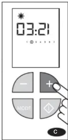
IMPORTANT
If the button is not pressed for 120 seconds, the appliance will automatically exit Programming mode.
Weekly Programming
a Hold down the Newton for 5 seconds to access the TIME.
b Press the Modfton to access weekly programming. PROG will appear on the display, with the programming for day 1.
Select the first day of the week you wish to programme by pressing the MODE, button. If you press it once, Monday (▶) will appear.
The preset programming for the seven days of the week will appear on the display:
00:00 - 8:00 Mode.
8:00 - 22:00 Mode.
C Each time has a temperature setpoint assigned. Those marked with two bars correspond to ⚙ mode and those marked with one bar correspond to ⭕ mode.
The times for which no heating is set (empty) maintain the mode setpoint ✿
d If you wish to change this programming, press the + button for ;mode, the - button for ) mode and the ◊ button for * mode. If you hold the button down it will scan through the settings faster.
Programming is done by hourly intervals and the selected time can be clearly seen as it will flash on the display.
The programming for Monday (▶) is now complete. If you wish to repeat this programming for other days, you may copy it.
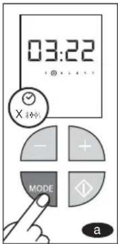
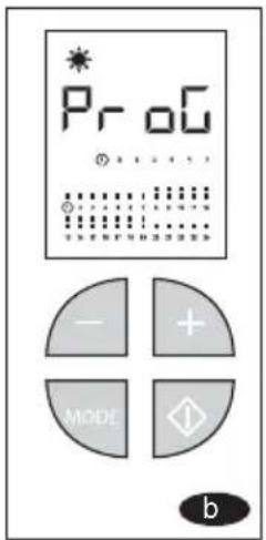


Copying the Programming
e Start with the day that has already been programmed, day ▶ (Monday).
f Hold down the MODE button for 5 seconds. When this time has elapsed, the triangle marking the days will go onto the next day, day▶2 (Tuesday), maintaining the programming.
Each day may also be programmed differently if you wish: simply press the MODE button once to go on to the next day.
IMPORTANT
If the button is not pressed for 120 seconds, the appliance will automatically exit Programming mode.

End of Programming
The Programming is complete when the seven days of the week have been programmed.
Viewing the Programming
When the Eco-Heater has been programmed and is functioning, the following will appear on the display: the day (Monday, for example), the flashing time programmed (12.00 midday, as shown in the example), and the operating mode (day mode, for example)

4 POWER CUTS
If a power cut occurs, the appliance will not work until the electricity returns. However, the Ecoheater has a batteryless power reserve that maintains all the selected settings with the display switched off.
5 OVERHEATING PROTECTION
Heat emission is greatly hindered if the appliance is totally or partially covered with clothing or any other objects.
In addition to preventing the appliance from functioning correctly, it will also cause it to overheat. The Eco-heater has a device that limits overheating of the appliance. When the cause of overheating has been rectified, the appliance will automatically start to function normally again.
However, if this occurs frequently, it may give rise to breakdown which will not be covered by the guarantee.

natural_image
Diagram of a heating element with airflow arrows indicating heat distribution (no text or symbols)
natural_image
Illustration of a smokestack emitting exhaust smoke, with a crossed-out black X symbol indicating no exhaust (no text or symbols present)IMPORTANT
NEVER COVER the top of the Eco-heater or OBSTRUCT the air flow in the lower part.
MAINTENANCE AND CLEANING OF THE APPLIANCE
No periodical technical maintenance is required.
Cleaning the outside of the appliance
The Eco-heater only requires cleaning from time to time. This can be done with a vacuum cleaner or a soft brush, or in the case of accidental spills or stains, simply use a damp cloth with a little neutral detergent. Do not use solvents or abrasive powders. The top grilles may be removed for cleaning. To do this, press the buttons on the rear and turn the grilles to the front. To replace the grilles, proceed in the same way but in reverse order, i.e. firstly rest the grilles on the front part and then turn them towards the rear so that the clips fi t into place.

natural_image
Illustration of a hand cleaning a wall-mounted electrical outlet with an electrical plug (no text or symbols)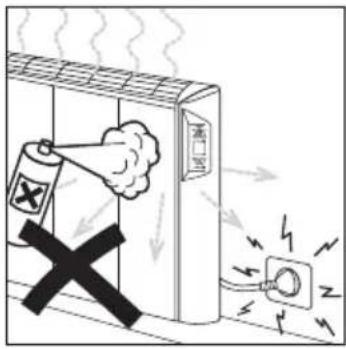

natural_image
Pure technical diagram of a mechanical component with arrows indicating direction (no text or symbols)
natural_image
Diagram of a mechanical assembly with an upward arrow indicating motion or force (no text or symbols present)
natural_image
Simple line drawing of a faucet spraying water onto a horizontal surface (no text or symbols)Recommendation
Leave the Eco-heater switched off if you will be away from home for a long period of time. Press the On/Off electric current master switch on the rear of the appliance.
IMPORTANT
Before carrying out any cleaning or maintenance operations, you should unplug the appliance from the mains.
The appliance is not heating up
a Check the appliance is plugged in and receiving electrical current (turn on the master switch on the right side of the rear of the appliance and check the display is on).
b Observe whether the word "ON" (consumption indicator) appears on the display. If it does not, increase the temperature setting until "ON" appears.
The appliance is hardly heating up
a Check whether the word "ON" (consumption indicator) appears on the display. If it appears and disappears, raise the temperature setting to increase the difference from room temperature. This will allow the appliance to heat continuously.
b The problem may be due to the air outlets having recently been obstructed (with clothing or towels, for example), causing the radiator temperature to increase and the thermostat to switch off the power. The safety thermostat functions automatically and the power will switch on again as soon as the appliance cools down.
Check that your home's power supply is of the correct voltage. Consult the Fagor calculation program (www.fagor.com) or an authorised Technical Service.
The appliance is making a noise
a If you switch off the appliance when it is hot, some noise may occur due to contraction. This is normal and does not indicate malfunctioning.
After checking the above, if the appliance continues to malfunction you should contact an Authorised Technical Service.
TECHNICAL ASSISTANCE
In case of breakdown or if you have any queries, you may call the user help line on

IMPORTANT
The Eco-heater is not equipped with a fuse or similar element that can be repaired by the user. In case of breakdown you should always contact an Authorised Technical Assistance Service.
CONDIÇÕES DE GARANTIA
natural_image
Pure architectural floor plan lines without any text, numbers, or symbolsNOTA ECOLÓGICA
natural_image
Diagram of a device rear panel with cable and connector, showing directional arrows indicating movement (no text or symbols)
2 COLOCAÇÃO NA CASA
Situação da casa
natural_image
Top-down floor plan of a dining area with table, chairs, and lamp (no text or labels)
natural_image
Simple line drawing of a room corner with a black X mark and window, no text or symbols present
natural_image
Diagram of a cabinet with upward arrows indicating movement or force, no text or symbols present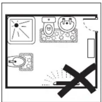
IMPORTANTE
natural_image
Technical line drawing of a mechanical clamp or bracket assembly with a tool inserted, showing no text or symbols.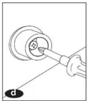
natural_image
Diagram of a mechanical component with a tool inserted, showing a circular housing and a base (no text or symbols)
natural_image
Pure technical line drawing of a mechanical component without any text, numbers, or symbols
natural_image
Diagram of a server rack with two hanging devices and connecting arrows indicating connection (no text or symbols)INNOVATION
natural_image
Line drawing of a rectangular industrial device with three vertical supports and a top panel (no text or symbols)natural_image
Technical line drawing of a rectangular electronic component with three vertical slots and mounting holes (no text or symbols)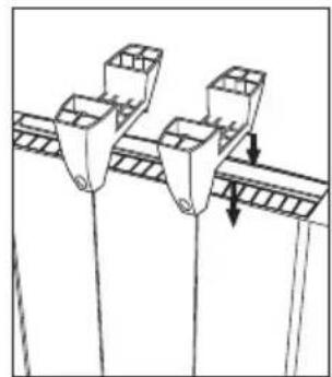
natural_image
Diagram of three identical mechanical components with downward arrows indicating force or movement (no text or symbols)natural_image
Line drawing of a solar panel installation with a power outlet and cable (no text or symbols)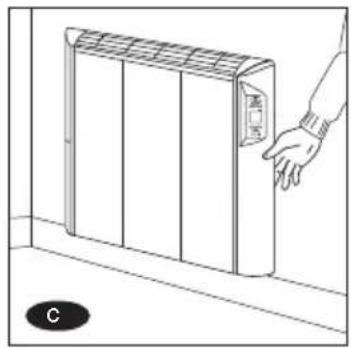
natural_image
Line drawing of a hand interacting with a wall-mounted air conditioner unit (no text or symbols)IMPORTANTE
ECRÃ RETRO-ILUMINADO
natural_image
Diagram of a heating unit with airflow arrows indicating heat distribution (no text or symbols)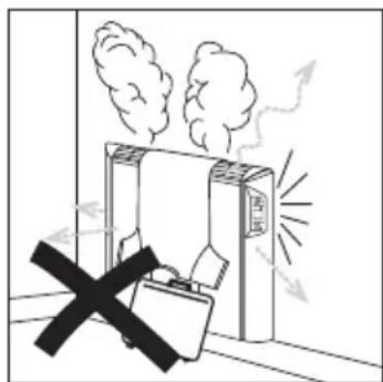
IMPORTANTE
NUNCA COBRIR o Eco-Emissor na zona superior, nem OBSTRUIR a passagem de ar na zona inferior.
natural_image
Illustration of a hand cleaning a wall-mounted electrical outlet with an electrical plug (no text or symbols)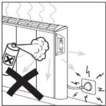

natural_image
Pure technical diagram of a mechanical component with arrows indicating direction (no text or symbols)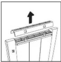
natural_image
Diagram of a mechanical assembly with an upward arrow indicating force or direction (no text or symbols present)
natural_image
Line drawing of a faucet spraying water onto a surface (no text or symbols)É aconselhável
natural_image
Pure schematic diagram of a mechanical or architectural component with no text, numbers, or symbolsΟΙΚΟΛΟΓΙΚΗ ΣΗΜΕΙΩΣΗ
natural_image
Diagram of a device rear panel with cable and connector, showing directional arrows indicating movement (no text or symbols)
2 ΘΕΣΗ ΣΤΗΝ ΟΙΚΙΑ
Θέση στην οικία
natural_image
Top-down architectural floor plan showing a dining table with chairs and furniture (no text or labels)
natural_image
Simple line drawing of a room corner with a black X mark, no text or symbols present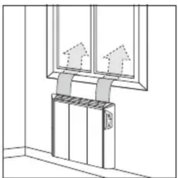
natural_image
Diagram of a ceiling-mounted elevator system with two vertical panels and a mounted base (no text or symbols)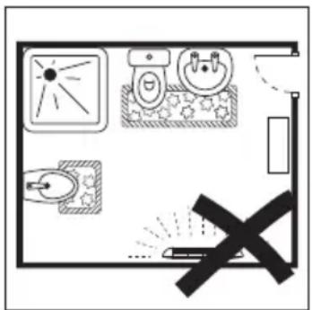
ΠΡΟΣΟΧΗ
natural_image
Technical line drawing of a mechanical device with labeled components and directional arrows (no text or symbols)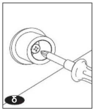
natural_image
Diagram of a mechanical component with a tool inserted into a circular housing (no text or symbols)
natural_image
Pure technical line drawing of a mechanical part with no text, numbers, or symbols
natural_image
Diagram of a server rack with two hanging devices and ventilation grilles, no text or symbols presentnatural_image
Line drawing of a three-panel air conditioner unit with cooling fins and mounting base (no text or symbols)natural_image
Technical line drawing of a rectangular electronic component with three vertical slots and mounting holes (no text or symbols)
natural_image
Diagram of two container-like structures with downward arrows indicating movement or force (no text or symbols)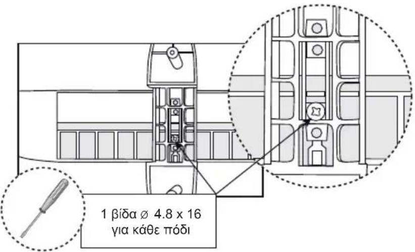
natural_image
Line drawing of a three-panel air conditioner unit with cooling fins and mounting base (no text or symbols)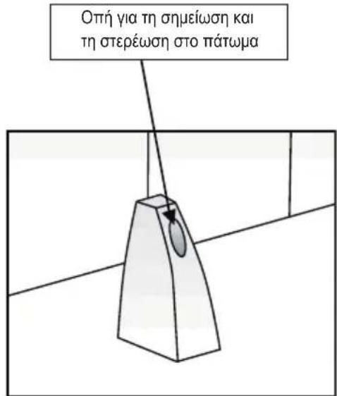
natural_image
Diagram of a heating unit with airflow arrows indicating heat or steam (no text or symbols)
natural_image
Illustration of a smokestack emitting exhaust with a briefcase and crossed-out X symbol (no text or labels)ΠΡΟΣΟΧΗ
natural_image
Illustration of a hand cleaning a window with an electrical outlet, showing wiring connections (no text or symbols)

natural_image
Pure technical line drawing of a structural component with arrows indicating direction (no text or symbols)
natural_image
Diagram of a mechanical or electrical component with an upward arrow, no visible text or symbols
natural_image
Simple line drawing of a faucet spraying water into a horizontal pipe (no text or symbols)Συνιστάται να
natural_image
Pure architectural floor plan lines without any text, numbers, or symbolsOHAR EKOLOGIKOA:
natural_image
Diagram of a device rear panel with cable and connector, showing directional arrows indicating movement (no text or symbols)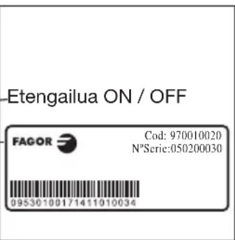
[2]
EKOIGORLEAREN KOKAPENA
natural_image
Top-down floor plan of a room with furniture layout (no text or labels)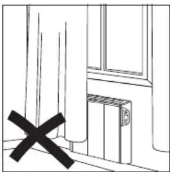
natural_image
Simple line drawing of a room with a black X mark and window, no text or symbols present
natural_image
Diagram of a elevator system with two upward arrows indicating direction (no text or symbols)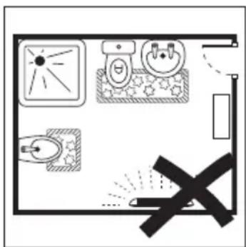
GARRANTZITSUA
natural_image
Technical line drawing of a mechanical device with two components and directional arrows (no text or symbols)
natural_image
Diagram of a hand holding a tool interacting with a circular component, labeled 'd' at the bottom (no text or symbols on the diagram itself)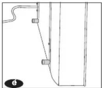
natural_image
Pure technical line drawing of a mechanical component without any text, numbers, or symbols
natural_image
Diagram of a server rack with two hanging devices and connecting cables (no text or symbols)
natural_image
Line drawing of a rectangular industrial or storage unit with three vertical supports and a top panel (no text or symbols)natural_image
Technical line drawing of a rectangular electronic component with three vertical slots and mounting holes (no text or symbols)
natural_image
Diagram of three identical mechanical components mounted on a support structure, with directional arrows indicating movement or force (no text or symbols present)natural_image
Line drawing of a cabinet with a wall-mounted fan and a small electrical outlet (no text or symbols)
natural_image
Line drawing of a hand pressing down on a wall-mounted air conditioner unit (no text or symbols)GARRANTZITSUA
natural_image
Diagram of a heating element with airflow arrows indicating heat distribution (no text or symbols)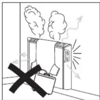
GARRANTZITSUA:
natural_image
Illustration of a hand cleaning a wall-mounted electrical outlet with an electrical plug (no text or symbols)

natural_image
Pure technical diagram of a mechanical component with two arrows indicating direction (no text or symbols)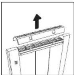
natural_image
Diagram of a mechanical assembly with an upward arrow indicating motion or force (no text or symbols present)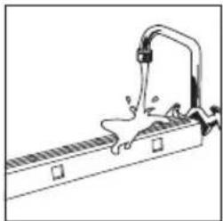
natural_image
Simple line drawing of a faucet spraying water onto a horizontal surface (no text or symbols)Gomendagarria da
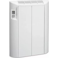
At the end of its working life, the product must not be disposed of as urban waste. It must be taken to a special local authority differentiated waste collection centre or to a dealer providing this service. Disposing of a household appliance separately avoids possible negative consequences for the environment and health deriving from inappropriate disposal and enables the constituent materials to be recovered to obtain significant savings in energy and resources. To remind you

that you must collaborate with a selective collection scheme, the symbol shown appears on the product warning you not to dispose of it in traditional refuse containers. For further information, contact your local authority or the shop where you bought the product.
NOTA ECOLÓGICA


- PORTUGUÊS
- NOTA ECOLÓGICA
- (2)
- IMPORTANTE
- Es aconsejable
- GUARANTEE EXCLUSIONS
- ANNULMENT OF THE GUARANTEE
- ECO-HEATER
- 0
- IMPORTANT WARNINGS
- INSTALLATION
- UNPACKING THE APPLIANCE
- ECO-NOTE
- [2]
- Location of your home
- Size of the home
- Location of the Eco-heater
- IMPORTANT
- (3)
- MOUNTING
- Wall-mounting
- a Position the Eco-heater in its
- Floor attachment accessory INNOVATION
- ELECTRICAL CONNECTION
- Electrical installation in the home
- Installing several appliances
- Installing an appliance.
- TECHNICAL CHARACTERISTICS
- PRESENTATION
- MODEL I MODEL IP
- BACKLIT LCD DISPLAY
- FUNCTIONAL CHARACTERISTICS
- Switching on the appliance
- Blocking the keypad
- Conf i guration
- Correcting the sensor temperature measurement
- Display backlight time adjustment
- PROGRAMMING (MODEL IP ONLY)
- Setting the Date and Time
- Weekly Programming
- Copying the Programming
- End of Programming
- Viewing the Programming
- POWER CUTS
- OVERHEATING PROTECTION
- MAINTENANCE AND CLEANING OF THE APPLIANCE
- Cleaning the outside of the appliance
- Recommendation
- The appliance is not heating up
- The appliance is hardly heating up
- The appliance is making a noise
- TECHNICAL ASSISTANCE
- CONDIÇÕES DE GARANTIA
- COLOCAÇÃO NA CASA
- Situação da casa
- ECRÃ RETRO-ILUMINADO
- É aconselhável
- ΟΙΚΟΛΟΓΙΚΗ ΣΗΜΕΙΩΣΗ
- ΘΕΣΗ ΣΤΗΝ ΟΙΚΙΑ
- Θέση στην οικία
- ΠΡΟΣΟΧΗ
- Συνιστάται να
- OHAR EKOLOGIKOA:
- EKOIGORLEAREN KOKAPENA
- GARRANTZITSUA
- GARRANTZITSUA:
- Gomendagarria da
Brand : FAGOR
Model : REIN-652I
Category : Heating