
PE1114A - Inverter ATEN - Free user manual and instructions
Find the device manual for free PE1114A ATEN in PDF.


| Product Type | Power Distribution Unit (PDU) |
| Form Factor | 1U Rackmount |
| Dimensions (W x D x H) | 482.6 x 200 x 44 mm (19 x 7.87 x 1.73 in) |
| Weight | 2.5 kg (5.5 lbs) |
| Input Voltage | 100-120V AC / 200-240V AC, 50/60 Hz |
| Input Connector | NEMA 5-20P or IEC 60320 C20 |
| Output Connectors | 8 x IEC 60320 C13 |
| Maximum Current | 15A (120V) / 10A (240V) |
| Power Capacity | 1800W (120V) / 2400W (240V) |
| Surge Protection | Yes, 1400 Joules |
| Overload Protection | Hydraulic-magnetic circuit breaker |
| Mounting | Horizontal, front or rear rack rails |
| Operating Temperature | 0°C to 50°C (32°F to 122°F) |
| Humidity Range | 0% to 95% non-condensing |
| LED Indicators | Power on, overload warning |
| Compliance | UL, CE, RoHS |
| Cleaning | Wipe with dry cloth, avoid liquids |
| Maintenance | Inspect monthly for dust buildup |
| Repairability | Replaceable power cord and circuit breaker |
| Warranty | 3 years limited |
Frequently Asked Questions - PE1114A ATEN
User questions about PE1114A ATEN
0 question about this device. Answer the ones you know or ask your own.
Ask a new question about this device
Download the instructions for your Inverter in PDF format for free! Find your manual PE1114A - ATEN and take your electronic device back in hand. On this page are published all the documents necessary for the use of your device. PE1114A by ATEN.
USER MANUAL PE1114A ATEN
Energy Intelligence by ATEN
eco PDU PE Series
SNMP Settings
User Instructions
User Information
Online Registration
Be sure to register your product at our online support center:
| International http://support.aten.com |
| North America http://www.aten-usa.com/product_registration |
Telephone Support
For telephone support, call this number:
| International 886-2-8692-6959 | |
| China 86-10-5255-0110 | |
| Japan 81-3-5615-5811 | |
| Korea 82-2-467-6789 | |
| North America 1-888-999-ATEN ext 4988 | |
| United Kingdom 44-8-4481-58923 | |
User Notice
All information, documentation, and specifications contained in this manual are subject to change without prior notification by the manufacturer. The manufacturer makes no representations or warranties, either expressed or implied, with respect to the contents hereof and specifically disclaims any warranties as to merchantability or fitness for any particular purpose. Any of the manufacturer's software described in this manual is sold or licensed as is. Should the programs prove defective following their purchase, the buyer (and not the manufacturer, its distributor, or its dealer), assumes the entire cost of all necessary servicing, repair and any incidental or consequential damages resulting from any defect in the software.
The manufacturer of this system is not responsible for any radio and/or TV interference caused by unauthorized modifications to this device. It is the responsibility of the user to correct such interference.
The manufacturer is not responsible for any damage incurred in the operation of this system if the correct operational voltage setting was not selected prior to operation. PLEASE VERIFY THAT THE VOLTAGE SETTING IS CORRECT BEFORE USE.
PE Device Safety Notice

- Set the maximum permissible breaker protection in the building circuitry to the current rating specified on the rating plate. Observe all national regulations and safety codes as well as deviations for breakers.
Only connect the PE Device to a grounded power outlet or a grounded system!
Make sure that the total current input of the connected systems does not exceed the current rating specified on the rating plate of the PE Device.
There is a risk of explosion if the battery is replaced with an incorrect type. Dispose of used batteries according to the relevant instructions.
Contents
Overview 1
Eco PDU 1
SNMP Trap Receivers....2
Eco Sensors 3
SNMP Parameters 4
Synchronizing SNMP Parameters....4
MIB Browser 5
Set SNMP Parameters ....6
Setting Up Thresholds....9
Setting Device/Outlet Status 10
Reading Device/Outlet Status 11
Introduction
This guide helps you to set up your PE series eco PDU and NRGence eco Sensors software for use with an SNMP manager. With support for SNMP V1, V2C and V3, your PE system can be configured to receive Set/Get commands in order to retrieve status updates and configure some basic settings (such as thresholds), as well as send traps to an SNMP manager.
In order to utilize SNMP functionality in your PE installation, it is important that all the parameters outlined in the following sections are synchronized for all eco PDUs in your installation. See Synchronizing SNMP Parameters, page 6, for further details.
There are three ways to utilize SNMP functionality with your NRGence device:
with the device's built-in graphical user interface (GUI)
- with eco Sensors power management software
- with a MIB browser
These are detailed in the following sections.
eco PDU
Graphical User Interface (GUI)
To configure the SNMP settings on an individual eco PDU via its graphical user interface (GUI), access the unit's Device Management page, shown below:

Note: Reference your eco PDU User Manual for full details about accessing the unit's Graphical User Interface via a Web browser.
The Device Management page allows super administrators, administrators, and users with device management permission to configure and control overall eco PDU operations. To configure the SNMP settings, click on the Device Configuration tab, and open the Event Notification section.
The Event Notification section is divided into four sections: SMTP Settings; Log Server; SNMP Trap Receivers; and Syslog Server. Scroll down to the SNMP Trap Receivers section, as shown below:
SNMP Trap Receivers

Up to four SNMP management stations can be specified. If you want to use SNMP trap notifications, do the following:
- Check Enable SNMP Trap.
- Select which version of SNMP you want to use.
- Key in the IP address(es) and the service port number(s) of the computer(s) to be notified of SNMP trap events. The valid port range is 1–65535. The default port number is 162.
Note: Make sure that the port number you specify here matches the port number used by the SNMP receiver computer.
- Key in the privacy password(s) that correspond to each of the stations.
Note: See Synchronizing SNMP Parameters, page 6, for further details.
eco Sensors
Power Management Software
The eco Sensors software uses the SNMP protocol to connect to the eco PDU units in your installation.
Note: For full details about eco Sensors software and how to install it on your system, see the eco Sensors User Manual. This can be found on the CD bundled with your PE package or downloaded from the ATEN website.
To configure the SNMP settings using eco Sensors software, open the System Management page. The page opens with the SNMP Settings tab displayed. This section allows you to set up your SNMP and system parameters so that eco Sensors can connect to the eco PDUs in your installation:

Default SNMP Agent Settings
This section allows you to set up your default SNMP and system parameters so that eco Sensors can connect to the NRGence devices in your installation:
- Enter a Username/Community, Port ID and Trap Port for the events.
- Set the timeout and retry values.
- Select the SNMP version, Privacy, and Authentication protocols from the drop-down menus.
- Key in the Privacy and Authentication passwords.
Note: Certain parameters in this section must match those of all the NRGence devices in the installation. See Synchronizing SNMP Parameters, page 6.
- Click Search. The devices will then be displayed in a list.
SNMP Trap Receiver
To be notified of SNMP trap events, do the following:
- Enter a Username, Port ID and Trap Port for the events.
- Set the timeout and retry values.
- Select the SNMP version, Privacy, and Authentication type from the dropdown menus.
- Key in the Privacy and Authentication passwords.
Note: Certain parameters in this section must match those of all the eco PDU devices in the installation. See Synchronizing SNMP Parameters, page 6.
System Parameters
♦ Enter the service delay time in seconds.
♦ Enter the Energy Box voltage in V.
Note: The EC1000 measures current only. Enter a reference voltage value here to calculate power and power dissipation in EC installations.
Synchronizing SNMP Parameters
In order for eco Sensors to access the NRGence devices on the installation, it is essential that three of the SNMP parameters are the same. These parameters are Username, Privacy PW, and Authen PW. The default values, which are the same for eco Sensors and eco PDU units, are shown in the following table:
| Parameter Default | It Web UI | |
| Username administrator | Administrator Account ID | |
| Privacy PW privacypwd | SNMP Privacy PW | |
| Authen PW password | Administrator Account Password |
If any of these parameters are modified on the Web GUI of the eco PDU device(s), the same parameters in eco Sensors must also be modified.
Note: eco Sensors will only access eco PDUs with the same parameters, so it is essential that these parameters are synchronized for all eco PDUs in your installation. Reference the Browser Operation chapter of your eco PDU User Manual for further information.
MIB Browser
Management Information Base
You can also use a MIB browser to configure the SNMP settings for your PE installation.
First, ensure that a suitable MIB browser is installed on your system. For illustration purposes, the iReasoning MIB Browser is used for the following screenshots:

Next, prepare the PE MIB file. This can be found on the CD bundled with your PE package or downloaded from the ATEN website. Extract the file and save it to a convenient location.
Note: As the MIB file may need to be reloaded each time you use the program, we recommend that you save the file in the default MIB file path location.
Then, load the MIB using File Load MIBs as below:

Once the MIB file has loaded, its corresponding MIB objects will be added in the appropriate location on the MIB tree hierarchy, as shown below:

Now, proceed to set the SNMP parameters.
Set SNMP Parameters
- In the Address field, input the DUT IP address.
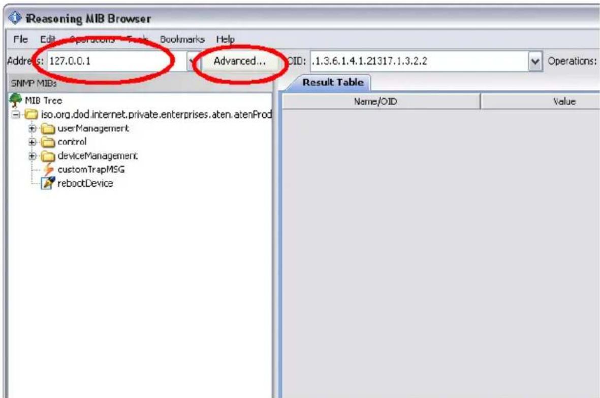
- Then click Advanced to open the SNMP settings window, as show below:

-
Enter values for the Port, Read Community, and Write Community fields (the example above shows the default settings). Then, select the SNMP version you want to configure from the dropdown menu. For v1 and v2, only the above fields are necessary. Click OK to save the settings.
-
If you select version 3 from the dropdown menu, a further SNMPv3 window containing more parameters appears, as shown below:

In the USM User field, enter the Default Community username; In the Auth Password field, enter the Default Authentication password; and in the Privacy password field, enter the Default Privacy password.
- For the Security Level, Auth Algorithm, and Privacy Algorithm fields, make your selections from the options in the dropdown menus.
Note: SNMPv3 for NRGence PE devices is currently available with the following settings: Security Level: auth. priv Auth Algorithm: MD5 Privacy Algorithm: AES
Setting Up Thresholds
To set up maximum and minimum Current and Voltage thresholds for each device and outlet using the MIB browser method, do the following:
- Under device → outletConfigTable in the MIB tree, locate the threshold that you want to configure – the example below shows maximum current per outlet.
- In the Results Table, click on the outlet that you wish to set the threshold for. The SNMP Set window appears:

Note: Once the MIB object has been selected in the tree, keyboard hotkey [Ctrl + b] will also open the Result Table. Select an item in the Result Table, and [Ctrl + b] will display its specific information.
- In the Value field, enter the threshold setting and click Save.
- Repeat this process for each outlet that you want to configure, and for both Current and Voltage threshold variables.
Note: Threshold settings can be entered at the device and/or outlet level, depending on your NRGence model.
Setting Device/Outlet Status
To power manage a device or an outlet (Power On / Power Off / Reboot) using the MIB browser method, do the following:
-
Under control → device or outlet in the MIB tree, locate the device or outlet that you want to power manage – the example below shows an outlet.
-
In the Results Table, click on the outlet. The SNMP Set window appears:
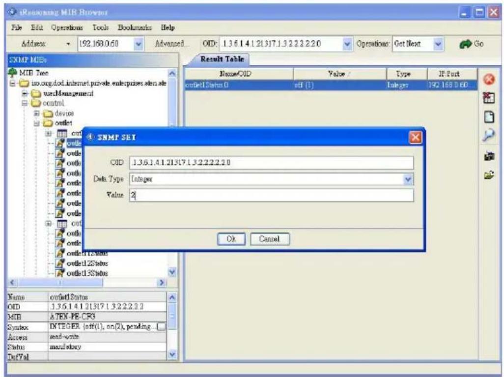
- In the Value field, enter the one of the following values:
◆ 1 – to power off a device/outlet
◆ 2 – to power on a device/outlet
◆ 4 – to reboot a device/outlet
Note: A value of 3 indicates “pending” and is a view-only value that cannot be entered.
- Click Save.
- Repeat this process for each device/outlet that you want to power manage.
Reading Device/Outlet Status
To read the status of a device or an outlet using the MIB browser method, do the following:
-
Under device → deviceValueTable, locate the variable that you want to read – the example below device current.
-
Click on the object in the MIB tree and the values are displayed in the Value column on the Results Page, as shown below:

To read status at the outlet level, navigate the MIB tree to that outlet.
Statuses for the following parameters are available:
- Current
♦ Voltage
Power
Power Dissipation

- Energy Intelligence by ATEN
- User Information
- Online Registration
- Telephone Support
- User Notice
- PE Device Safety Notice
- Contents
- Introduction
- eco PDU
- Graphical User Interface (GUI)
- SNMP Trap Receivers
- eco Sensors
- Power Management Software
- Default SNMP Agent Settings
- SNMP Trap Receiver
- System Parameters
- Synchronizing SNMP Parameters
- MIB Browser
- Management Information Base
- Set SNMP Parameters
- Setting Up Thresholds
- Setting Device/Outlet Status
- Reading Device/Outlet Status
Brand : ATEN
Model : PE1114A
Category : Inverter