
SP100 - Uncategorized ATEN - Free user manual and instructions
Find the device manual for free SP100 ATEN in PDF.


| Product Type | USB to Serial Converter |
| Model | SP100 |
| Brand | ATEN |
| Host Interface | USB 2.0 Type A |
| Serial Interface | RS-232 DB9 Male |
| Baud Rate | Up to 115200 bps |
| Data Bits | 5, 6, 7, 8 |
| Parity | None, Even, Odd, Mark, Space |
| Stop Bits | 1, 1.5, 2 |
| Flow Control | None, RTS/CTS, XON/XOFF |
| Power Supply | Bus-powered via USB |
| Power Consumption | 0.5 W (max) |
| Dimensions (L x W x H) | 60 x 30 x 18 mm |
| Weight | 50 g |
| Supported OS | Windows, macOS, Linux |
| Operating Temperature | 0°C to 60°C |
| Storage Temperature | -20°C to 80°C |
| Humidity | 5% to 95% RH (non-condensing) |
| Certifications | FCC, CE |
| Maintenance | Clean with a dry cloth; no internal serviceable parts |
Frequently Asked Questions - SP100 ATEN
User questions about SP100 ATEN
0 question about this device. Answer the ones you know or ask your own.
Ask a new question about this device
Download the instructions for your Uncategorized in PDF format for free! Find your manual SP100 - ATEN and take your electronic device back in hand. On this page are published all the documents necessary for the use of your device. SP100 by ATEN.
USER MANUAL SP100 ATEN
3. Service Tray Application....11
3.1. Start Monitor....11
3.2. Stop Monitor....12
3.3. SNMP Manager....12
3.3.1. SNMP Device List....13
3.3.2. SNMP Manager Function Menu....17
3.4. Configuration....24
4. ViewPower Pro GUI 30
5. ViewPower Pro Menu....31
5.8. Configuration....31
5.8.1. Password Setting....31
5.8.2. Group area....32
5.8.3. UPS setting....33
5.8.4. SMS....34
5.8.5. E-mail....35
5.8.6. Load configuration....36
5.8.7. Event action....38
5.8.8. Log setting 40
5.8.9. EMD Manager....40
5.8.10. Modbus communication setting....42
5.9. Schedule 43
5.9.1. Scheduled on/off....43
5.9.2. Scheduled battery self-test....44
5.9.3. Wake on LAN schedule 45
5.10. View 46
5.10.1. Centralized monitoring....46
5.10.2. History....56
5.11. Format....61
5.11.1. Temperature Unit....61
5.11.2. Date Format....61
5.12. Language....62
5.13. Help....62
5.13.1. About 62
5.13.2. Online help....62
1. ViewPower Pro Overview
1.1. Introduction
ViewPower Pro is an advanced UPS management software which is perfect for home users and enterprises. It can monitor and manage from one to multiple UPSs in a networked environment including LAN, INTERNET and RS485-based networks. Integrated with Shutdown Wizard, it can not only prevent data loss from power outage and safely shutdown systems, but also store programming data and scheduled shut down UPSs. All UPS working data and event records can be kept in local database system.
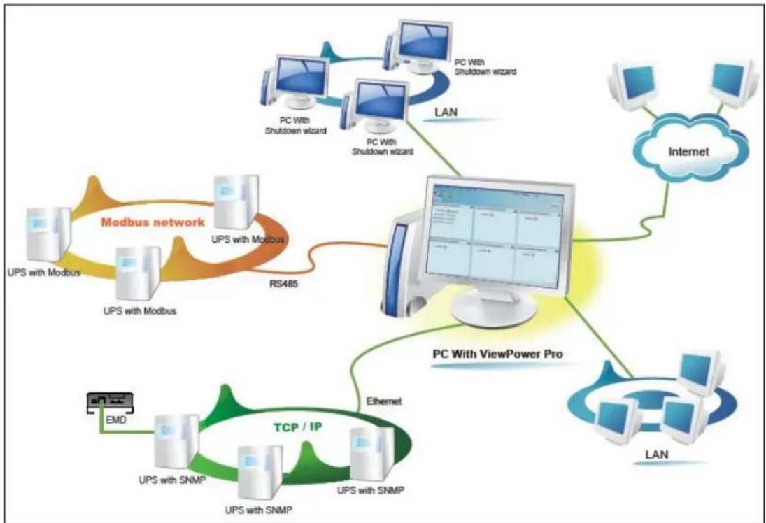
flowchart
graph TD
    A["PC With Shutdown wizard"] --> B["PC With Shutdown wizard"]
    B --> C["LAN"]
    C --> D["Internet"]
    D --> E["PC With ViewPower Pro"]
    E --> F["TCP / IP"]
    F --> G["UPS with SNMP"]
    F --> H["UPS with Modbus"]
    F --> I["RS485"]
    I --> J["Modbus network"]
    J --> K["UPS with Modbus"]
    J --> L["UPS with Modbus"]
    J --> M["EMD"]
    M --> N["TCP / IP"]
    N --> O["UPS with SNMP"]
    N --> P["UPS with Modbus"]
    N --> Q["Internet"]
    Q --> R["LAN"]
1.2. Structure
ViewPower Pro includes monitor service, WEB service and tray service.
Monitor service: It is the core of ViewPower Pro software. Monitor service automatically find UPSs in the networks, store UPS working data and event information. It will communicate with UPS, record events, notify users with events, and execute command according to the users' request.
WEB service: It offers Http or Https service for local or remote users. Users can manage and monitor UPSs for real-time status, information and modify UPS setting parameters via browser such as IE and Firefox.
Tray service: It is management tool for ViewPower Pro software. It includes start monitor, stop monitor, SNMP manager and so on.
1.3. Features
➢ Centralized control and monitor up to 1000 UPSs via SNMP or Modbus networks.
➢ Offers WEB service to allow remote monitoring service via Intranet or Internet.
- Offers quick overview for UPS monitoring in Text and Graphic view.
Offers user-customized background picture for graphic view with simple drag and drop.
➢ Scheduled UPS on/off, battery test, and scheduled wake on LAN programs.
2. ViewPower Pro Install and Uninstall
2.1. System requirement
● 1 GB physical memory at least (2 GB is recommended)
- 2 GB hard disk space at least
- Administrator authority is required
- More than 16-bit colors and 800 x 600 or above resolution display is recommended
- TCP/IP protocol must be installed for network management
- Platforms supported by software are listed below:
Windows 2000
Windows XP/2003/Vista/2008 (32-bit & x64-bit)
Windows 7 (32-bit & x64-bit)
Windows SBS 2011
Linux RedHat 8, 9
Linux RedHat Enterprise AS3, AS5, AS6 (32-bit)
Linux RedHat Enterprise AS6 (64-bit)
Linux RedHat Enterprise 5.2 (32-bit & 64-bit)
Linux SUSE 10 (32-bit & 64-bit)
Linux Cent OS 5.4 (32-bit)
Linux Ubuntu 8.X, 9.X, 10.X (32-bit)
Linux Ubuntu 10.X (64-bit)
Linux Ubuntu 12.04 (32-bit & 64-bit)
Linux Fedora 5
Linux OpenSUSE 11.2 (32-bit & 64-bit)
Linux Debian 5.x, 6.x (32-bit)
Linux Debian 6.x (64-bit)
Mac OS 10.6 (x64-bit)
Mac OS 10.7 (x64-bit)
➤ Solaris 10 for x86 (32-bit)
2.2. Software Install
Step 1 Insert the software CD into CD ROM. Installation menu will be automatically displayed, or you can run autorun.exe to start the installation in CD directory. Refer to the diagram 2-1.

Diagram 2-1
Step 2 It will show the following screen as Diagram 2-2. Then click "ViewPower Pro" button to start the installation.
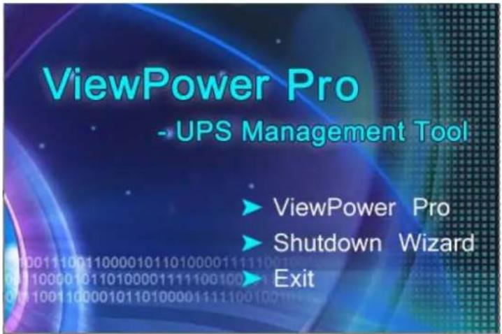
Diagram 2-2
Step 3 After clicking install, it will display the installation in process. Refer to the diagram 2-3.
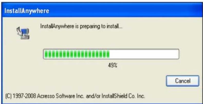
Diagram 2-3
Step 4 Choose wanted language and click "OK" as diagram 2-4.
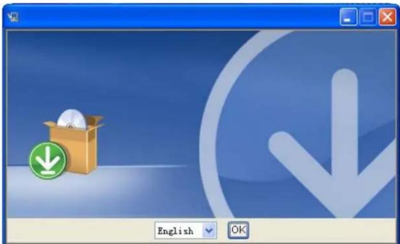
Diagram 2-4
Step 5 Click "Next" to proceed to the next screen as Diagram 2-5.
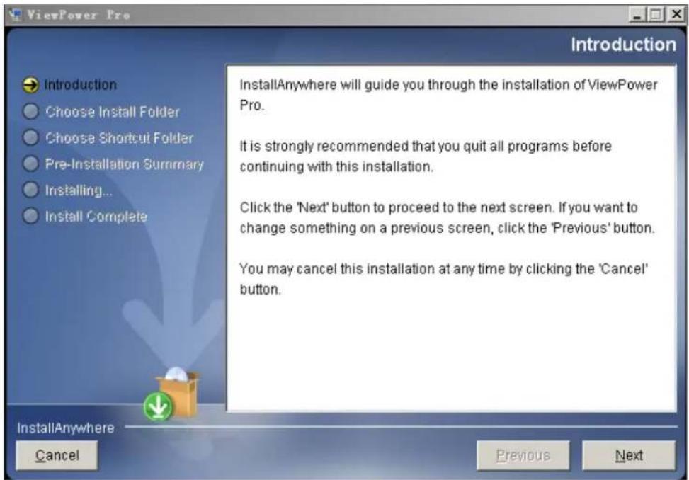
Diagram 2-5
Step 6 Click "Choose" button to change the default folder. After choosing the installed folder, click "Next" button. Refer to the following diagram 2-6.
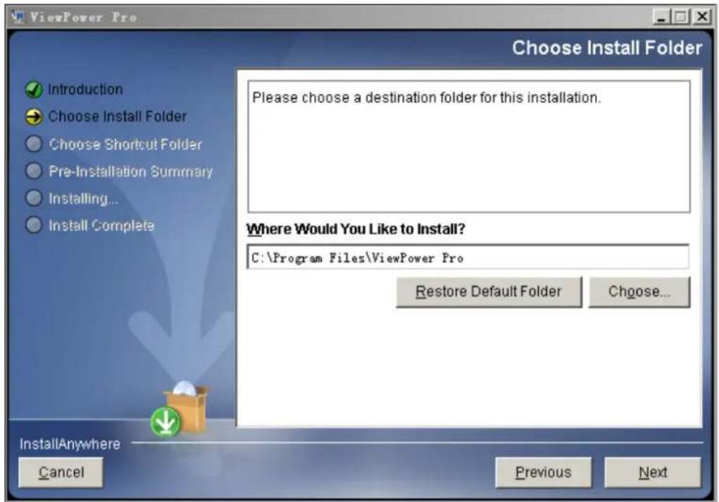
Diagram 2-6
Step 7 Choose the shortcut folder and click "Next" button. Refer to the
following diagram 2-7.
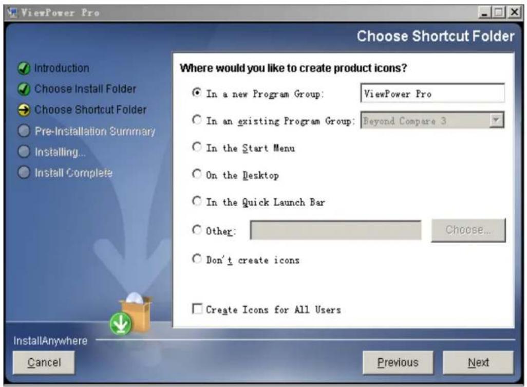
Diagram 2-7
Step 8 It will display the software summary before installation. Click "Install" button to start the installation and refer to Diagram 2-8.
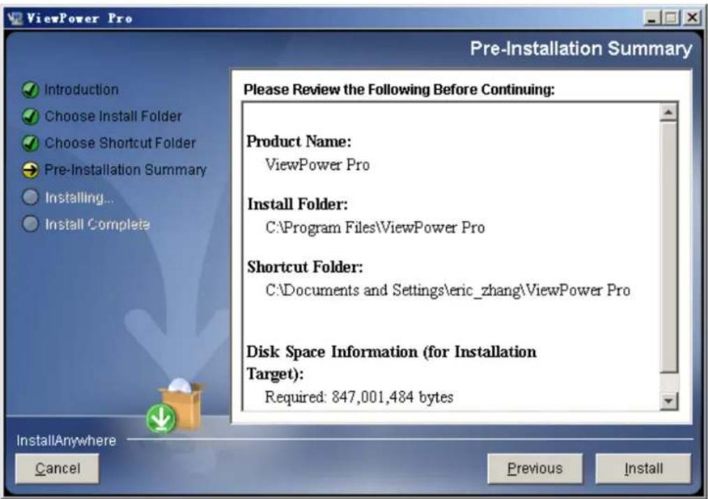
Diagram 2-8
Step 9 Click "Done" button to confirm the installation completely. Refer to Diagram 2-9.
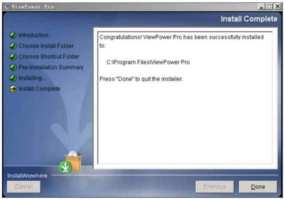
Diagram 2-9
Note: Please uninstall the previous version before install the new version software.
If detecting installed ViewPower Pro during installation, it will remind users to uninstall old version first. Refer to Diagram 2-10.
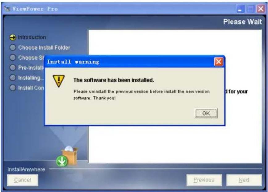
Diagram 2-10
2.3. Software Uninstall
Please choose Start>>All Programs>>ViewPower Pro>>Uninstall. Then follow the on-screen instruction to uninstall the software. Before uninstall software, you must stop all software programs first and then log in as "Administrator"! Otherwise, it can't be uninstalled completely.
3. Service Tray Application
The Installer will leave a shortcut icon on your desktop. Simply click the shortcut. Then it will start the software and display an orange plug icon located in taskbar. To launch the GUI, double click the plug icon or choose "Open Monitor" by clicking right button of the mouse. Refer to below diagram.
Or, use the Start Menu method; Start>>All Programs>>ViewPower Pro>>ViewPower Pro.
Shortcut icon

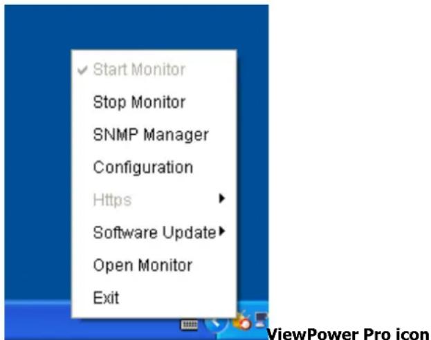
3.1. Start Monitor
This software will be automatically activated when installing it as service application. At this time, users can remote monitor UPSs through web browser even though users do not login in operation system.
If service application can not be registered successfully, when starting up tray service, it will automatically activate monitoring application. If it's failed or stopped manually, simply click "Start Monitor" to activate it.
"Start Monitor" will check if monitoring application is registered as service
application. If it's successfully, this software will be activated from service mode. If not, this software will be activated as monitoring mode. Users can identify the application mode from tray icon as below:
● Monitoring application is not activated successfully:

● Monitoring application is activated as service mode:

● Monitoring application is activated as monitoring mode:

3.2. Stop Monitor
Click "Stop Monitor" to stop monitoring application.
3.3. SNMP Manager
SNMP Manager is a plug-in utility for ViewPower Pro to search and operate all SNMP devices in the LAN.
Click the "SNMP Manager" to access SNMP management tool.
It has four sections as marked in the illustration below:
![SNMP Manager System Settings Language IP address UPB name Address Note 192.168.107.230 UPS1 F1 TEST B SNMP status: 1 SNMP reset enable Teret Use system time: 09/19/2012 10:13:55 Apply 192.168.107 Scan Add Del Basic Info IP settings Online upgrade System management Static trap address IP address 192.168.107.230 MAC address 80-18-29-00-00-1B UPS name UPS1 Address F1 Note TEST Apply Output window [10.06.27] 192.168.107.97 Online successfully. [10.08.22] Wrong password entered. Please retry to logon [10.08.26] Operation success [10.08.33] 192.168.107.230 Online successfully. [10.08.34] 192.168.107.230 Online successfully. [10.08.35] 192.168.107.230 Online successfully.](/content/2026/05/1001144/images/28fd208598f0b90e579e51d52588d8cbd92fd0ebf06593ef507d936640bc4c35.jpg)
Diagram 3-1
A. Function menu offers tool-set for setting SNMP devices.
B. SNMP device list can list down all SNMP devices with IP address.
C. Configuration area includes IP settings, online upgrade, password management, and static trap address.
D. Output window displays all messages for operations
3.3.1. SNMP Device List
The default value in window list would be current PC IP address. For example, if IP address of current PC is "192.168.102.10", it will display "192.168.102" in list when first enabling SNMP Manager.
Scan
You may enter specific IP address and then click "Scan" button to search.
Add
Click "Add" button and it will pop up a window to ask for entering specific IP address. Then, click "Apply" button to add IP address (Subnet). Refer to Diagram 3-2.
![SNMP Manager System Settings Language IP address UPS name Address Note 192.168.107.230 UPS1 F1 TEST SNMP status: 1 SNMP reset enable Reset Use system time: 09/13/2012 10:15:51 Apply 192.168.107 Scan Add Del Basic Info IP settings Online upgrade System management Static trap address IP address 192.168.107.230 MAC address 00-19-29-00-00-1B UPS name UPS1 Address F1 Note TEST Apply Please enter the IP address. 192.168.103 Apply Cancel [10:08 27] 192.168.107.97 Online successfully. [10:08 22] Wrong password entered. Please rely to logon. [10:08 26] Operation success [10:08 33] 192.168.107.230 Online successfully. [10:08 34] 192.168.107.230 Online successfully. [10:08 35] 192.168.107.230 Online successfully.](/content/2026/05/1001144/images/95c981cd070e971478a7c14ee927177f6ef0ae56f9696bbbd960ff3df2a46491.jpg)
Diagram 3-2
Delete
You may select IP address from the list and remove it by clicking "Del" button.
SNMP Status
It will display SNNP status, 0 or 1, after selecting IP from the IP list. If there is program inside of selected SNMP card, the status becomes 1. If not, it will
display 0. If no IP address is selected, it will display “---” as default. Refer to Diagram 3-3.
![SNMP Manager System - Settings : Language IP address UPS name Address Note 192.168.107.230 UPS1 F1 TEST SNMP status: 1 SNMP reset enable Reset Use system time: 08/13/2012 10:16:26 Apply 192.168.107 192.168.103 Scan Add Del Basic info IP settings Online upgrade System management Static trap address IP address 192.168.107.230 MAC address 00.16-29.00-00.1B UPS name: UPS1 Address F1 Note TEST Apply Output window [10.06.27] 192.168.107.97 Online successfully. [10.08.22] Wrong password entered. Please retry to logon. [10.08.26] Operation success [10.08.33] 192.168.107.230 Online successfully. [10.08.34] 192.168.107.230 Online successfully. [10.08.35] 192.168.107.230 Online successfully.](/content/2026/05/1001144/images/74b29eaf68edb6f31d59e4819385b8e5a6938258c1d8ced4cd4737ff6ae16d74.jpg)
Diagram 3-3
Reset
If it is required to restart the IP addresses of devices, please select the checkbox of "SNMP reset enable" and click "Reset" button. Then, if login is confirmed, you can restart the device. Steps are as follows:
Step1: Select IP address needed to restart IP from the list. Then, "SNMP reset enable" will become available to select. Refer to Diagram 3-4.
![SHMP Manager System Settings Language IP address UPS name Address None 192.168.107.230 LPS1 F1 TEST SNMP status: 1 SNMP reset enable Reset Use system time: 09/13/2012 10:15:26 Apply 192.168.107 192.168.103 Scan Add Del Basic Info IP settings Online upgrade System management Static trap address IP address 192.168.107.230 MAC address 60-19-29-06-00-18 UPS name UPS1 Address F1 Note TEST Apply Output window [10.08:27] 192.168.107.97 Online successfully. [10.08:22] Vering password entered. Please retry to logos. [10.08:26] Operation success [10.08:33] 192.168.107.230 Online successfully. [10.08:34] 192.168.107.230 Online successfully. [10.08:35] 192.168.107.230 Online successfully.](/content/2026/05/1001144/images/a57f8c0848a723cdeb077d56b89647737405e39616e429e89ebbac8e27c64db0.jpg)
Diagram 3-4
Step2: Click checkbox of "SNMP reset enable". Then, "Reset" button will become available to click. Refer to Diagram 3-5.
![SNMP Manager System Settings Language IP address UPS name Address Note 192.168.107.230 UPS1 F1 TEST SNMP status: 1 ✓ SNMP reset enable Reset Use system time: 09/13/2012 10:16:37 Apply 192.168.107 Scan 192.168.103 Add Del Basic Info IP settings Online upgrade System management Static trap address IP address 192.168.107.230 MAC address 80-19-29-00-00-1B UPS name UPS1 Address F1 Note TEST Apply Output window [10.06.27] 192.168.107.97 Online successfully. [10.08.22] Wrong password entered. Please retry to logon. [10.08.26] Operation success [10.08.33] 192.168.107.230 Online successfully. [10.08.34] 192.168.107.230 Online successfully. [10.08.35] 192.168.107.230 Online successfully.](/content/2026/05/1001144/images/268907034e5235817c6c81e40c9dbdf3da4ce0436f5149ac5216deacf2ff7f25.jpg)
Diagram 3-5
Step3: Click "Reset" button and it will pop up a message to confirm this operation. Refer to Diagram 3-6.
![SNMP Manager System Settings Language IP address UPS name Address Note 192.168.107.230 UPS1 F1 TEST SNMP status: 1 SNMP reset enable Reset Use system time: 09/01/30/2012:10:16:48 Apply 192.168.107 192.168.103 Scan Add Del Basic Info IP settings Online upgrade System management Bstatic trap address IP address 192.168.107.230 MAC address 60-19-29-00-00-16 UPS name UPS1 Address F1 Note TEST Confirm Are you sure to operate? 192.168.107.230 Yes No Output window [10.08.27] 192.168.107.9T Online successfully. [10.08.22] Wrong password entered. Please retry to logon. [10.08.26]Operation success [10.08.33] 192.168.107.230 Online successfully. [10.08.34] 192.168.107.230 Online successfully. [10.08.35] 192.168.107.230 Online successfully.](/content/2026/05/1001144/images/4de2c80204802cb055495e34f055936977598684d0d43be94aab1349b9786365.jpg)
Diagram 3-6
Step4: If "Yes" is selected, it's requested to log in first. If "No" is selected, it will stop this operation. Refer to Diagram 3-7.
![SNMP Manager System Settings Language IP address UPS name Address None 192.168.107.230 UPS1 F1 TEST Basic Info IP settings Online upgrade System management Static trap address IP address 192.168.107.230 MAC address 60-19-28-00-00-18 UPS name UPS1 Address F1 Note TEST Apply Please login first Password:****** Login Cancel SNMP status: 1 ✓ SNMP reset enable Reset Use system time: 08/13/2012 10:17:44 Apply 192.168.107 192.168.103 Scan Add OK [10.06.27] 192.168.107.97 Online successfully [10.06.22] Wrong password entered. Please retry to logon. [10.06.26] Operation success [10.06.33] 192.168.107.230 Online successfully [10.06.34] 192.168.107.230 Online successfully [10.06.35] 192.168.107.230 Online successfully [10.17.18] 192.168.107.230 Online successfully [10.17.23] 192.168.107.230 Online successfully](/content/2026/05/1001144/images/011a98b0794d7469d751cf6e5ce70da16c15b051084c3d410e84aa94bd7171d9.jpg)
Diagram 3-7
Step5: Enter the correct password and click "Login" button. The target device will be restarted.
NOTE: If changing the MAC address of current device before reboot and the current device is applying DHCP (Automatically obtain IP address) method, you need to manually click "Scan" button to scan.
Use system time
If "Use system time" is selected, the SNMP card will apply PC system time. Refer to Diagram 3-8.
![SNMP Manager System Settings Language IP address UPS name Address Note 192.168.107.230 UPS1 F1 TEST SNMP status 1 SNMP reset enable Reset Use system time: 08/13/2012 10:18:02 Apply 192.168.107 Scan 192.168.103 Add Cut Basic Info IP settings Online upgrade System management Static map address IP address 192.168.107.230 MAC address 88-15-29-60-09-18 UPS name UPS1 Address F1 Note TEST Apply Output window [10:08:27] 192.168.107.97 Online successfully [10:08:22] Wrong password entered. Please reply to logen. [10:08:26] Operation success [10:08:23] 192.168.107.239 Online successfully [10:08:34] 192.168.107.239 Online successfully [10:08:35] 192.168.107.239 Online successfully [10:17:10] 192.168.107.239 Online successfully [10:17:23] 192.168.107.239 Online successfully](/content/2026/05/1001144/images/7c62e5d0e653974f2cf131757974f56381499cc140d23fcd232bdc2e7c87ef52.jpg)
Diagram 3-8
3.3.2. Function Menu
3.3.2.1. System
3.3.2.1.1 Login
It's necessary to verify ID to remote access SNMP devices. The default password is "12345678".
Step 1: Select System >> Login
Step 2: Enter default password and then click "Login" button. Or click "Cancel" to cancel login. Refer to Diagram 3-9.
![SNMP Manager System Settings Language IP address UPB name Address None 192.168.107.230 UPS1 F1 TEST SNMP status: 1 SNMP reset enable Reset Use system time: 09/13/2012 10:18:43 Apply 192.168.107 Scan 192.168.103 Add Dul Basic Info IP settings Online upgrade System management Static trap address IP address 192.168.107.230 MAC address 60-19-29-00-00-18 UPB name UPS1 Address F1 Note TEST Please login first Password ****** Login Cancel [10.06.27] 192.168.107.97 Online successfully. [10.08.22] Wrong password entered. Please retry to logon. [10.08.26] Operation success [10.08.33] 192.168.107.230 Online successfully. [10.08.34] 192.168.107.230 Online successfully. [10.08.35] 192.168.107.230 Online successfully. [10.17.18] 192.168.107.230 Online successfully. [10.17.23] 192.168.107.230 Online successfully.](/content/2026/05/1001144/images/e125fef20564579ee5f420740e29caf614378c802edc46287149e7665aaf888f.jpg)
Diagram 3-9
Logout
Clear all currently saved passwords.
Quit
Select "Quit" to exit SNMP Manager.
3.3.2.2 Settings
Basic Info
User can manually enter basic information of SNMP cards such as UPS name, Address, and Note for verification. Refer to Diagram 3-10.
![SNMP Manager System Settings Language IP address UPS name Address Note 192.168.107.230 UPS1 F1 TEST SNMP status: 1 SNMP reset enable Reset Use system time: 09/13/01/2 10:19:02 Apply 192.168.107 Scan 192.168.103 Add Del Basic Info IP settings Online upgrade System management Static trap address IP address 192.168.107.230 MAC address 80-19-29-00-00-1B UPS name UPS1 Address F1 Note TEST Apply Output Window [10:06:27] 192.168.107.97 Online successfully. [10:08:22] Wrong password entered. Please reply to region. [10:08:26] Operation success [10:08:33] 192.168.107.230 Online successfully. [10:08:34] 192.168.107.230 Online successfully. [10:08:35] 192.168.107.230 Online successfully. [10:17:18] 192.168.107.230 Online successfully. [10:17:23] 192.168.107.230 Online successfully.](/content/2026/05/1001144/images/2ef2fbf2386ae3d3161ae8247e1913cd1e9b8a262334f68cfadb6752abb9bf74.jpg)
Diagram 3-10
IP Setting
![SNMP Manager System Settings Language IP address UPS name Address Nuote 192.168.107.230 UPS1 F1 TEST SNMP status: 1 SNMP reset enable Reset Use system time: 09/13/2012 10:19:33 Apply 192.168.107 192.168.103 Scan Add Dst Basic Info IP settings.Online upgrade System management Static trap address Automatically obtain IP address Use a static IP address IP address 192.168.107.230 A Subnet mask 255.255.255.8 Default Gateway 192.168.107.254 Apply DNS Apply B Output window [10.06.27] 192.168.107.97 Online successfully. [10.08.22] Wrong password entered, Please retry to logon. [10.08.26] Operation success [10.08.33] 192.168.107.230 Online successfully. [10.08.34] 192.168.107.230 Online successfully. [10.08.35] 192.168.107.230 Online successfully. [10.17.18] 192.168.107.230 Online successfully. [10.17.23] 192.168.107.230 Online successfully.](/content/2026/05/1001144/images/67511a6edb2a9d626d95104a6ff9423df7209a14a06fd7a766abaedfed5ce88e.jpg)
Diagram 3-11
Part A: There are two methods to obtain IP address. Refer to section A in Diagram 3-11.
● Automatically obtain IP address (DHCP)
It will allow system to automatically obtain IP addresses. If there is no this kind of service provided in LAN, the default IP will display as
"192.168.102.230", Subnet mask as "255.255.255.0" and default gateway as "0.0.0.0". Simply click "Apply" button to apply this change.
- Use a static IP address
It will allow users to enter static IP address for SNMP devices. When entering IP address, Subnet mask, and gateway address, simply click "Apply" button to apply this change.
Part B: Enter the DNS and click "Apply" button. Refer to section B in Diagram 3-11.
Online upgrade
![SNMP Manager System Settings Language IP address UPG name Address Notes 192.168.107.230 UPS1 F1 TEST SNMP status: 1 SNMP reset enable reset Use system time: 09/19/2012 10:22:30 Apply 192.168.107 192.168.103 Scan Add Del Basic Info IP settings Online upgrade System management Static trap address Target file path:CX0201-06.519 Browse ● Upgrade the selected devices ○ Upgrade all un-upgraded devices ○ Force to upgrade all devices 0% Upgrade Cancel Output window [10.06.27] 192.168.107.97 Online successfully. [10.08.22] Wrong password entered. Please retry to logon [10.08.26] Operation success [10.08.33] 192.168.107.230 Online successfully. [10.08.34] 192.168.107.230 Online successfully. [10.08.35] 192.168.107.230 Online successfully. [10.17.18] 192.168.107.230 Online successfully. [10.17.23] 192.168.107.230 Online successfully.](/content/2026/05/1001144/images/8cc782eda056aac5d4f7c7bbc8181d16f0e81d3e807381b5cde2a8c4aa4cd2a8.jpg)
Diagram 1-12
There are three methods for online upgrade:
- Upgrade the selected devices: It will upgrade all SNMP devices listed in the IP list.
- Upgrade all un-upgraded devices: It will only upgrade SNMP devices which are not using the latest version.
- Force to upgrade all devices: No matter what kinds of version are used for SNMP devices listed in the IP list, it will upgrade to the latest version for all SNMP devices. Refer to Diagram 3-12.
Step 1: Click "Browse" button to choose program file. Refer to Diagram
3-13.
![SNMP Manager System Settings Language IP address UPB name Address Note 192.168.107.230 UPS1 F1 TEST Target file path C:\0201-06.S19 Browse Open Lock Inc: snmp 0201-02.S19 SNMP status: 1 SNMP res Use system time: 00/13/2012 10:23:10 192.168.107 192.168.105 Scan Add Del File Name: 0201-02.S19 Files of Type: All Files Open Cancel [10/17/23] 192.168.107.230 Online successfully.](/content/2026/05/1001144/images/abc2f95c1932acc1944e81131518ed5d331918fad5620dd0d3ebea611751e7fb.jpg)
Diagram 3-13
Step2: Click "Upgrade" button to execute upgrade action. Refer to Diagram 3-14.
![SNMP Manager System Settings Language IP address UPB name Address Note 192.168.107.230 UPS1 F1 TEST SNMP status: 1 SNMP reset enable Reset Use system time: 09/13/2012 10:23:53 Apply 192.168.107 192.168.103 Add Add Del Basic Info IP settings Online upgrade System management Stats trap address Target file path:C:\02\01-06.519 Browse • Upgrade the selected device • Upgrade will install and install • Forward update all devices 79% Upgrade Cases Output window [10.08.33] 192.168.107.230 Online successfully. [10.08.34] 192.168.107.230 Online successfully. [10.08.35] 192.168.107.230 Online successfully. [10.17.16] 192.168.107.230 Online successfully. [10.17.23] 192.168.107.230 Online successfully. [10.23.36] 192.168.107.230 Wrong password entered. Please retry to logon. [10.23.34] 192.168.107.230 Ready to upgrade for the 1 time. [10.23.35] 192.168.107.230 Start formatting. [10.23.44] 192.168.107.230 Formatting is completed. [10.23.44] 192.168.107.230 Upgrading files. Please wait.](/content/2026/05/1001144/images/cc313e3112f496b4d342dd304ac641daaa9980f284644166d5ec184c7faaaa85.jpg)
Diagram 3-14
Step3: When upgrade is complete, you may check the message in output window. Refer to Diagram 3-15.
![SNMP Manager System Settings Language IP address UPS name Address None 192.168.107.230 UPS1 F1 TEST SNMP status: 1 SNMP reset enable Reset Use system time: 06/13/2012 10:23:58 Apply Scan Add Del Basic Info IP settings Online upgrade System management Static trap address Target file path:C:\02\01-06.516 Browse ● Upgrade to the selected device ○ Upgrade all un-upgraded devices ○ Force to upgrade all devices 100% Upgrade Cancel Output window [10.09.34] 192.168.107.230 Online successfully. [10.09.35] 192.168.107.230 Online successfully. [10.17.10] 192.168.107.230 Online successfully. [10.17.23] 192.168.107.230 Online successfully. [10.23.30] 192.168.107.230 Wrong password entered. Please retry to logon. [10.23.34] 192.168.107.230 Ready to upgrade for the 1 time. [10.23.39] 192.168.107.230 Start formatting. [10.23.44] 192.168.107.230 Formatting is completed. [10.23.44] 192.168.107.230 Upgrading files. Please wait. [10.23.55] 192.168.107.230 Upgrade is completed.](/content/2026/05/1001144/images/e3f6fe4b201141e7c4457194624034ec612780aa2a592b252fdcd49c4dd2b05f.jpg)
Diagram 3-15
NOTE: If abnormal situation occurs during upgrade process, the system will automatically re-start the upgrade operation. If this interruption occurs five times, then, system will automatically stop this operation. At this time, please check if LAN is working well.
System management
![SNMP Manager System Settings Language IP address UP S name Address Note 192.168.107.230 UPS1 F1 TEST SNMP status: 1 SNMP reset enable Reset Use system time: 06/03/2012 10:24:21 Apply 192.168.107 192.168.103 Scan Add Del Basic Info IP settings Online upgrade System management Static trap address Version setting: Version: 72 Encrypt None Proving None Select device Select all Password: Old password: New password: Confirm password: Select device Select all Apply Output window: [0.08:34] 192.168.107.230 Online successfully. [0.08:35] 192.168.107.230 Online successfully. [0.17:16] 192.168.107.230 Online successfully. [0.17:23] 192.168.107.230 Online successfully. [0.23:30] 192.168.107.230 Wrong password entered. Please reply to logos. [0.23:34] 192.168.107.230 Ready to upgrade for the 1 time. [0.23:38] 192.168.107.230 Start formatting. [0.23:44] 192.168.107.230 Formatting is completed. [0.23:44] 192.168.107.230 Upgrading files. Please wait. [0.23:55] 192.168.107.230 Upgrade is completed.](/content/2026/05/1001144/images/215986a0b7b78138722a184ffeb3602d66a0cac4692d81badb454a6a9cd5bd4e.jpg)
Diagram 3-16
Part A: You can set SNMP protocol version for selected or all devices. Simply choose SNMP protocol version first. The default setting is V2. If choosing V3, it's also necessary to set encrypt. Select devices to apply this setting.
- Select device: Set SNMP protocol version for selected SNMP devices from device list.
- Select all: Set SNMP protocol version for all SNMP devices from device list.
Then, click "Apply" button to complete version setting.
Part B: You may modify single password for one SNMP device or all passwords for all SNMP devices. Please enter original password, new password and re-enter new password. Select devices to apply this setting.
- Select device: Choose to change password for selected SNMP device from device list.
- Select all: Choose to change passwords for all SNMP devices on the window list
Then, click "Apply" button to change password.
NOTE: The length of password is 8\~15 digits. If this change is applied for all SNMP devices, the password will be consistent for all SNMP devices.
Static trap address
You may configure two static trap addresses and change trap port in SNMP Manager. The default trap port is 162. Refer to Diagram 3-17.
![SNMP Manager System Settings Language IP address UPS name Address None 192.168.107.230 UPS1 F1 TEST SNMP status: 1 SNMP reset enable Reset Use system time: 09/13/2012 10:25:30 Apply 192.168.107 192.168.103 Scan Add Del Basic Info P settings Online upgrade System management Static trap address Trap IP Address IP address 1 192.168.107.123 IP address 2 192.168.102.24 A Select device Select all Apply Trap com. Communication port 162 Apply Output window [10.08:34] 192.168.107.230 Online successfully [10.09:35] 192.168.107.230 Online successfully [10.17:18] 192.168.107.230 Online successfully [10.17:23] 192.168.107.230 Online successfully [10.23:30] 192.168.107.230 Wrong password entered. Please retry to login. [10.23:34] 192.168.107.230 Ready to upgrade for the 1 time. [10.23:39] 192.168.107.230 Slot formatting. [10.23:44] 192.168.107.230 Formatting is completed. [10.23:44] 192.168.107.230 Upgrading files, Please wait. [10.23:55] 192.168.107.230 Upgrade is completed.](/content/2026/05/1001144/images/70ca493c471b614163da391fde60f3653f3b531a9e2a10d6a64b7edb9e575bcb.jpg)
Diagram 3-17
NOTE: This software allows SNMP device to send trap messages to 2 static
trap addresses and 8 dynamic trap addresses. It will default define host computer with software installed as a dynamic trap address. If communication failure occurs between SNMP card and host computer for over 10 minutes, it will stop sending trap message.
3.3.2.3 Language
SNMP Manager offers 12 languages:
√ Chinese(Simplified)
√ Chinese(Traditional)
√ English
√ German
√ Italian
√ Polish
√ Portuguese
√ Russian
√ Spanish
√ Turkish
√ Ukrainian
√ French
The default language setting is "English".
3.4. Configuration
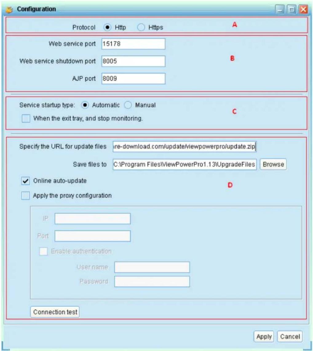
Diagram 3-18
3.4.1. Https/Http
Communication protocol: If choosing Https, "Https" selection will be accessible from tray menu. If communication port of Https is fixed in "18443", it's not allowed to use "port modification". At the same time, the URL of monitoring screen will become:
https://xxx.xxx.xxx.xxx:18443/ViewPowerPro
If choosing Http, “Https” selection will not be accessible and “port modification” function will become active status. (Refer to section A in
Diagram 3-18):
If port conflict occurs, you may modify value of port. The default setting for port is listed as below (Refer to section B in Diagram 3-18):
- Web Service port: 15178
- Web service shutdown port: 8005
- AJP port: 8009
You may modify the value of port to any number between 0 and 65536. If value is applied already, the system will remind users to enter another number again.
NOTE1: Please do not modify port value unless port conflict occurs. This modification will affect remote monitoring website. For example, if changing web service port to 15177, then the remote monitoring website will change to: http://xxx.xxx.xxx.xxx:15177/ViewPowerPro
NOTE2: To avoid possible conflicts, please be sure to enter value at least 4 digits.
3.4.3. ViewPower Pro Start and Exit Setting
Refer to section C in Diagram 3-18 for the detailed configuration of ViewPower Pro start and exit setting:
- Server startup type: If "Auto" is selected, the software will automatically start up when PC is turned on. If "Manually" is selected, users have to manually start the ViewPower Pro software.
- Exit to stop monitoring: If selected, it will completely exit software without monitoring service. If unselected, it will continue monitoring service in the back end even though exit from software.
3.4.4. Software Upgrades
Refer to section D in Diagram 3-18 for the detailed configuration for online
upgrade:
- Specify the URL for update files: This is the directory to online update software. Please do not change it unless it's instructed by software vendor.
- Save files to: The directory to save files.
- Online auto-update: If selected, it will automatically check if there is any new version launched online every 1 hour.
-
If applying online upgrade, please follow below for configuration:
-
Select "Apply the proxy configuration";
- Enter IP address and port of server;
- If ID identification is requested, select "Enable authentication" and enter User Name and Password.
- Connection test: Click this button to test if all configurations are set up well.
3.4.5. Configuration Saved
Click "Apply" button to save all changes in Configuration page. Click "Cancel" to stop the change.
3.5. Https
Https section includes "Certificate Generation" and "Import Certificate".
- Certificate Generation: it will automatically generate a numeral certificate according to the information users enter. Refer to Diagram 3-19:
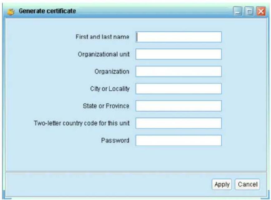
Diagram 3-19
Note 1: Please enter internet domain name and IP address in "First and last name" column.
Note 2: Password should be at least 6 characters in length.
- Import Certificate: It will import a https certificate from a third party. It supports JKS and PCKS12 types of certificate. Refer to Diagram 3-20.
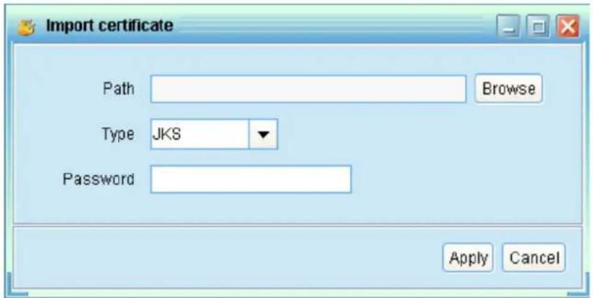
Diagram 3-20
3.6. Software Update
Software update includes Online Update and Manually Update:
- Online Update:
Click "Online Update" to search the latest software version. If there is new version detected, it will automatically download and update. Refer to Diagram 3-21:
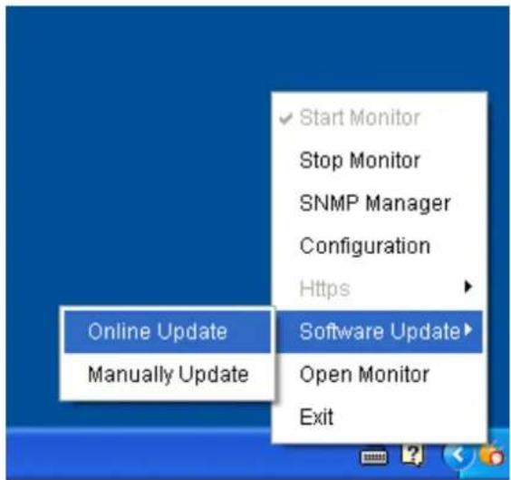
Diagram 3-21
- Manually Update:
Users can manually update the software. Follow below steps:
- Click "Manually Update" from function menu. Refer to Diagram 3-22.
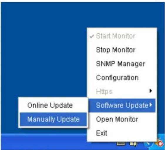
Diagram 3-22
- Click "Browse" to choose file directory. And then click "Upgrade" to upgrade software. Refer to Diagram 3-23.
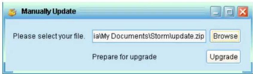
Diagram 3-23
3.7. Open Monitor
Click "Open Monitor" to open monitoring webpage.
3.8. Exit
Click "Exit" to exit service application.
4. ViewPower Pro GUI
ViewPower Pro GUI includes function menu, shortcut button, login section and main screen. Refer to diagram 4-1:
![Configuration Schedule View Format Language Help A User type: Guest Login B C Graphic view List view Unassigned [192.168.103.166_SNMPPO1_000000000000] UPS information: Line mode Input information: 238.3V/50.0Hz Output information: 229.8V/50.0Hz Battery Information: 41.0V/100% null[192.168.103.165_SNMPPO1_000000000001] Disconnected null[192.168.103.164_SNMPPO2_000000000002] Disconnected null[192.168.103.163_SNMPPO1_000000000003] null[192.168.103.162_SNMPPO0_00000000004] null[192.168.103.161_SNMPPO3_000000000005] Disconnected Disconnected](/content/2026/05/1001144/images/a8fd3ef791965cffd8745626eaebe8f632ea35469d6ed1545a07672036f27f1c.jpg)
Diagram 4-1
A .Function Menu
It offers complete tool-set for navigation and setting the GUI.
B. Login section
It shows user type for current login user.
C. Shortcut button
- Centralized monitoring.
- Password, group area, UPS setting, SMS, E-mail, load configuration, event action, log setting, EMD manager, modbus communication setting.
- Scheduled on/off, scheduled battery self-test, and scheduled wake-on-LAN setting.
- Event log, event statistics, data, diagram, and EMD log.
- Refresh.
D. Main Screen
It will display information and/or control alternatives according to function
menu or shortcut menu selected.
5. ViewPower Pro Menu
5.8. Configuration
5.8.1. Password Setting
It's password configuration for administrator only. The default user name and password is "administrator". Before operating and configuring the software, please login and modify the default password first for security concern. Users can only browse UPS status and information as Guest status without login as an Administrator. Guest can NOT control or execute any setting.
Step 1 Select Configuration>>Password. Refer to Diagram 5-1.
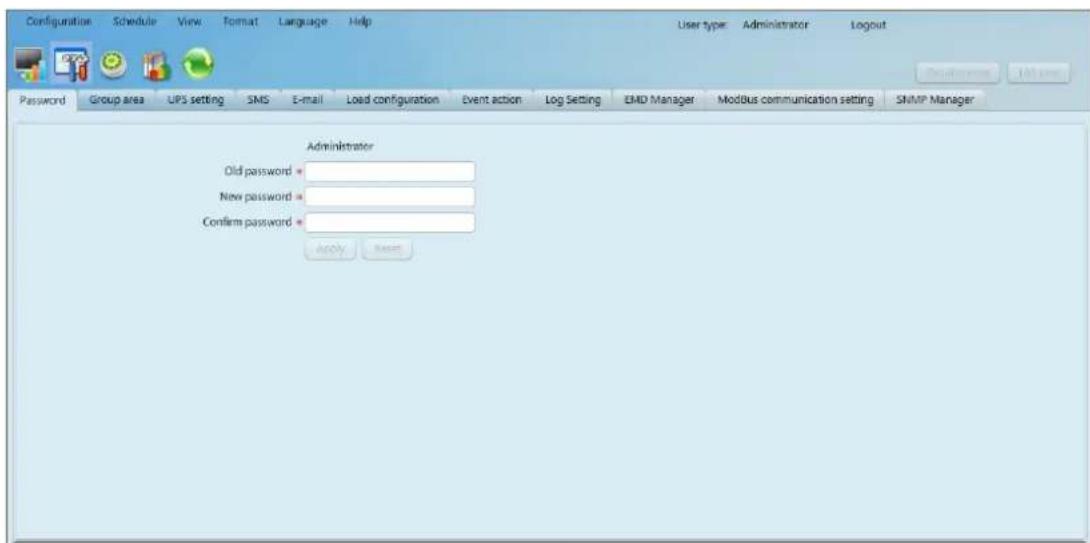
Diagram 5-1
Step 2 Enter old password and type twice new password to modify password for administrator. (The password should be at least 6 digits) Then click "Apply" button to successfully modify password for administrator.
NOTE1: Simply click "Login" button on the top right corner to log in the software.
NOTE2: If password is forgotten, it's necessary to re-install the software.
5.8.2. Group area
Select Configuration>>group area, user can assign monitored UPSs into different groups for best management. ViewPower Pro has a default group called "Unassigned". When a UPS is detected, it will automatically put in the "Unassigned" group. Users are able to not only create and customize groups here, but also assign groups in "UPS setting". Refer to diagram 5-2.
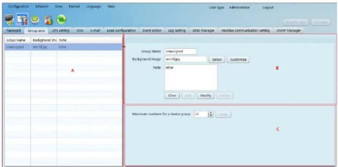
Diagram 5-2
Section A Group list: Shows group information;
Section B Group editor: add/delete, set up and modify group;
Background image: Click "Customize" button to import preferred image into software as background for graphic view. Or users can simply select preferred photos from default image database by clicking "Select" button.
Add group: Add group into group list in section B. Then click "Add" button to add.
Modify group: Select a group from the list in section A to modify the current setting and it will show the current setting in section B directly. After entering new data, simply click "Modify" button to update setting.
Delete group: Select the group which needs to delete from the list on section A. Then click "delete" button to delete.
Note1: Default group can only be modified, NOT allow to delete.
Note2: When "Add" button is disabled, first execute "Clear" operation.
Section C Maximum numbers for a device group: It means maximum numbers will be shown in each group.
5.8.3. UPS setting
Select Configuration >> UPS setting. It helps users to assign or re-assign groups for monitored UPSs. When a new UPS is detected, it will automatically put in default group - "Unassigned". Refer to diagram 5-3:
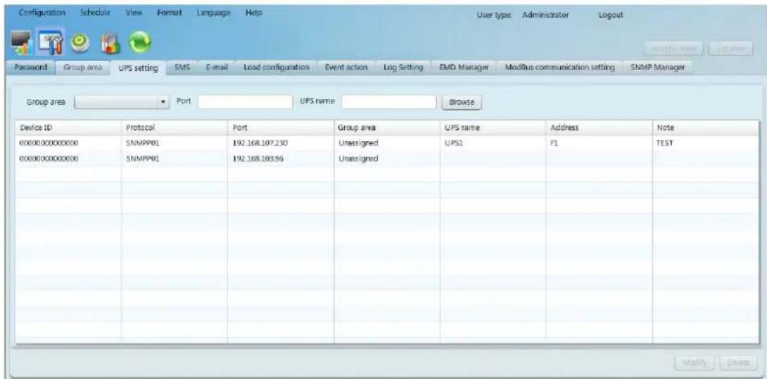
Diagram 5-3
▶ Query
User can query information according to the Group area, Port, UPS name by clicking each column tab.
Modify
Select UPS that need to modify from the list and click "Modify" button for modification. It will pop up information board of each monitored UPS and users can assign or re-assign UPSs to group area. It also can enter the UPS location and name here for internal reference. Click "Apply" button to save all changes. Refer to diagram 5-4:
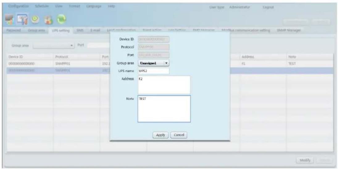
Diagram 5-4
Delete
Select UPS and click "Delete" button to remove it from the list.
5.8.4. SMS
It's for entering SMS receiver list. In the event of an alarm condition occurring, a message about UPS status will be sent to the specified users via mobile phone. For the event receiving list, please configure in "Event Action" page (refer to section 5-8-7).
- Choose Configuration >> SMS. Refer to Diagram 5-5:
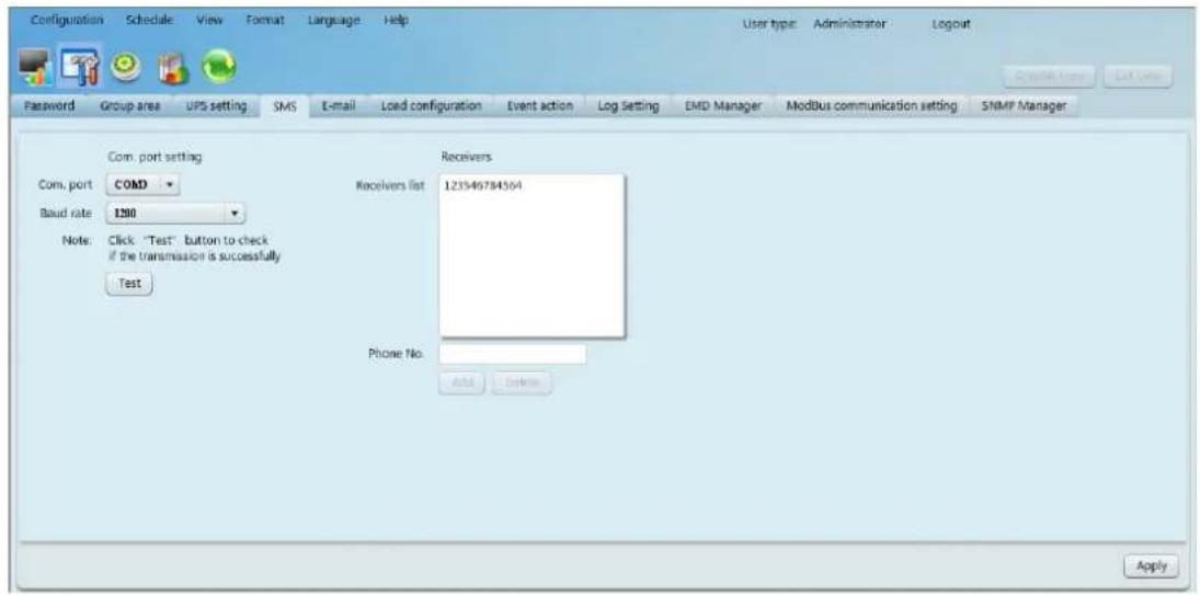
Diagram 5-5
-
Select communication port and baud rate.
-
Enter mobile phone numbers in "Phone no." column and click "Add" button to add phone no. in Receivers List. To delete numbers, simply select phone no. from "Receivers list" and click "Delete".
- Click "Apply" button to save all changes. The "Test" button can be used to send tests SMS to confirm the correct operation. If all parameters are set up correctly, system will send a test message to all receivers and pop up a successful message. Otherwise, it will pop up a failure dialog to indicate there is an error for parameter setting.
NOTE: It's required to plug-in GSM Modem if sending SMS to mobile phones.
5.8.5. E-mail
This feature enables the configuration to send alarm mail by SMTP server. For the event receiving list, please configure in "Event Action" page. Refer to 5-8-7. To use this function, the e-mail service must be correctly configured in the computer. All values in this function page are default empty. This action can't be executed without the SMTP information, e-mail account and password. Besides, the sender account should be allowed for SMTP/POP3 forwarding.
Select Configuration >> E-mail. Refer to Diagram 5-6
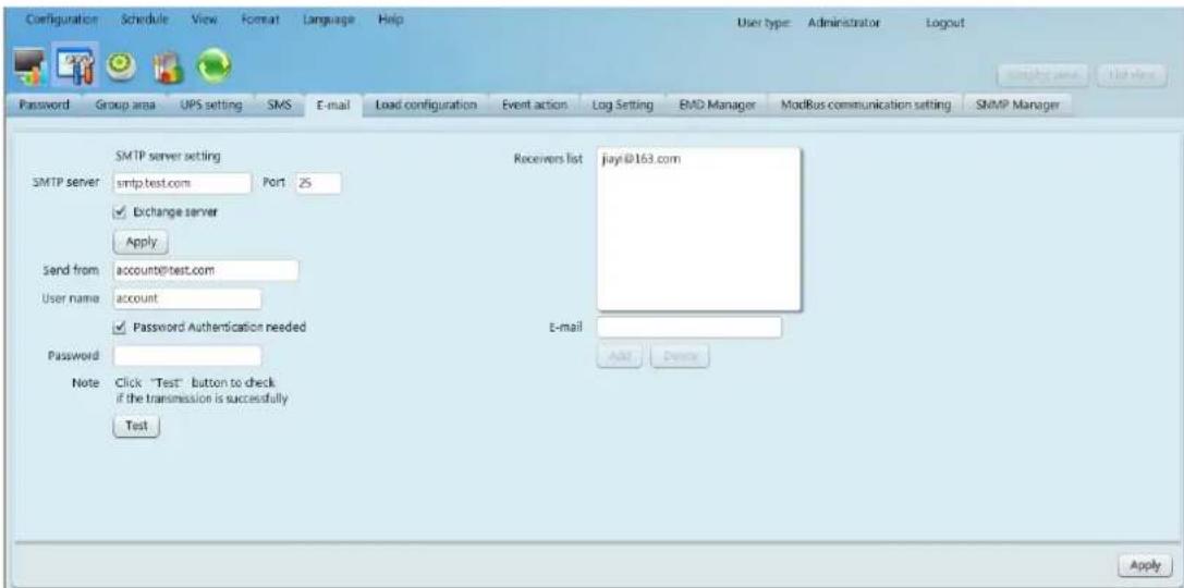
Diagram 5-6
- Enter SMTP server, SMTP port, Send from E-mail address, User name and password. Click checkbox of password authentication needed for password verify. If using Exchange Server for mailbox system, it's required to configure Exchange server domain name in SMTP sever and select "Exchange server". Then, click "Apply" button.
- Enter correct e-mail accounts in E-mail column. Then click "Add" to add into receivers list. To delete e-mail account, simply select accounts from Receivers list and click "Delete" button.
- Click "Apply" to save all changes. The "Test" button can be used to send a test e-mail to all receivers to confirm correct operation. When the test e-mails are successfully sent to specific recipients, it will pop up a successful message on operated PC. Otherwise, it will pop up a failure dialog to indicate there is an error for parameter setting.
5.8.6. Load configuration
Load configuration can remotely manage other computers via intranet or internet. It can set up remote computers in power-off options, MAC address, execute file action, whether accept scheduled UPS shutdown or not, waiting time for load shutdown and so on. In addition, it also allows one computer to communicate with multiple UPSs. When any event occurs on UPS, the software can configure reactions of the monitored UPS via communicated computer.
- Select Configuration>>load configuration, refer to diagram 5-7:
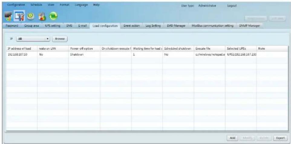
Diagram 5-7
- Add: Add load information (one computer) by clicking "Add" button. Refer to diagram 5-8:
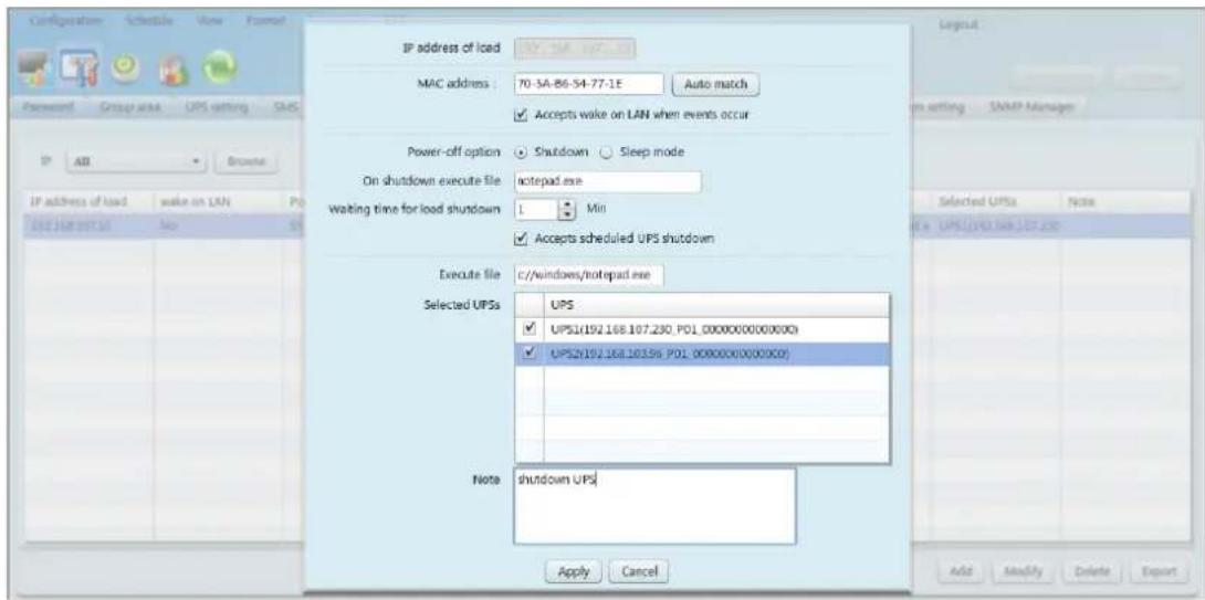
Diagram 5-8
- Enter the IP address of this computer. Then, enter MAC address of this computer. Users also can get MAC address by clicking "Auto match" button when the connection is well.
● Power-off option: Selecting power-off method for above shutdown system.
Shutdown: When clicking the checkbox, the selected system will shut down. The default setting is clicked.
Sleep mode: When clicking the checkbox, selected system will
suspend the system instead of a normal shutdown. But this function is only supported by Windows 2000 or higher on supported hardware.
- On shutdown execute file: Enter the path of execute file.
- Waiting time for load shutdown: If selecting "Accepts scheduled UPS shutdown", enter to waiting time for load shutdown before shutting down UPS.
- Selected UPS: Select UPSs to execute shutdown action when entered PC is shut down.
Click "Apply" button to save all changes.
- Modify: Select one from list to modify configuration by clicking "Modify" button. User can also click "Delete" button to delete this information.
- Export: Users can export load setting table in PDF format by clicking "Export" button.
5.8.7. Event action
It is to set up reactions after events occur. Select Configuration>>Event action, refer to diagram 5-9:
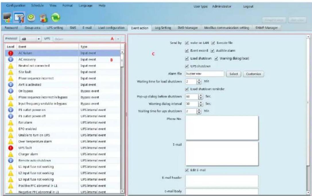
Diagram 5-9
Section A: List all detected UPSs. The system default is all UPSs.
Section B: UPS event list.
Section C: Event action editor
Select UPS from section A and then select event from section B. When selecting event, it's necessary to set up at least one reaction from section C. Click "Apply" button to save setting.
This software provides seven reactions for UPS events.
Wake on LAN: It is a technology to remotely wake up one computer by a network message. It is also required to have ATX power and hardware support for remote PCs to implement this function. When event occurs, this software will wake up PC by clicking this checkbox.
➢ Execute file: When event occurs, it will request connected computer to execute file.
Event record: When event occurs, it will save the event records to the database.
Audible alarm: When event occurs, it will play selected media file. If user wants to use customized sound, it's necessary to import media file into software by clicking "Customize" button. And then, select this imported media file by clicking "Select" button.
Load shutdown: When event occurs, it will notify Shutdown wizard on remote PCs to shut down computer.
➢ Warning dialog (local): When event occurs, it will pop up message box to notify users.
SMS: When event occurs, it will send event message to receivers via mobile phone.
E-mail: When event occurs, it will send mail to receivers via email. And you can edit E-mail.
- UPS shutdown: When event occurs, it will shut down the UPS.
Note 1: When editing receiver list in SMS or e-mail columns, it's
necessary to refresh the event action page to update receiver list.
Note 2: Event list will be different according to different types of UPS.
5.8.8. Log setting
➢ Refresh frequency: The setting range for "Refresh frequency" is 2\~600 seconds. It will affect the displayed data refreshed in software screen.
Record interval: Users can set up "Record Interval", "The max. Numbers of logs for historical data" and "The max. Numbers of logs for historical events" according to real situation.
The setting range for "Record interval" is 30\~600 seconds. It will effect history data displayed under View >> History >>Data.
- Select configuration>>Log setting. Refer to Diagram 5-10:
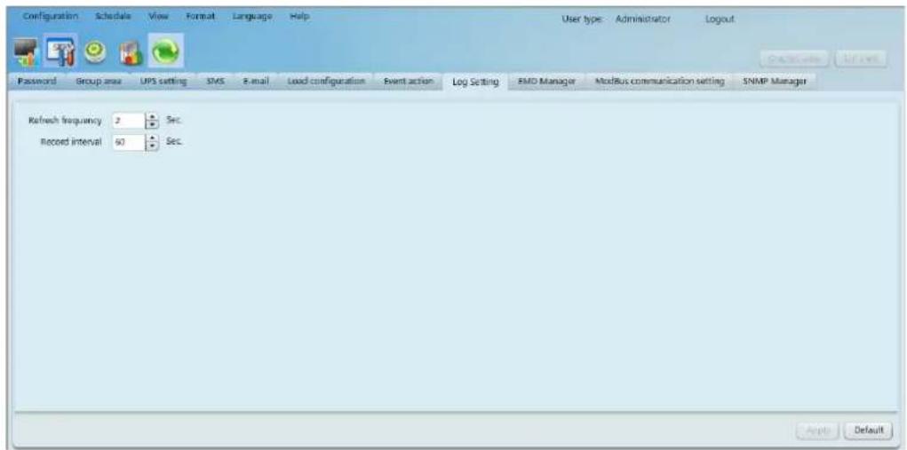
Diagram 5-10
- Enter time interval and click "Apply" button to save all settings.
- Click "Default" button to recover the default setting.
5.8.9. EMD Manager
EMD Manager is used to manage Environmental Monitoring Devices. Users can define events and set message texts for each event. It also can set up warning points for temperature, humidity and smoke of devices.
- Dry contact event: Users can define events and set event level. After event is successfully added, users can configure and set alarm. Refer to Diagram 5-11.
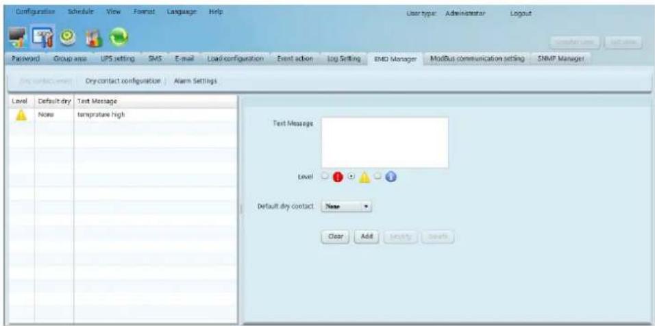
Diagram 5-11
Text Message: The description of the dry contact event.
Default dry Contact: Define dry contact no. to send event message. There are five selections: none, 1, 2, 3 and 4. If selecting any value from 1 to 4, any environmental monitoring device (EMD) which is detected defined event will send event message. If selecting none, it means this event is defined as special event. Then, users can assign specific environmental monitoring device (EMD) to receive this event message. Please refer this special event setting in “Dry contact configuration” section.
- Dry contact configuration: Users can define special events with assigned dry contact no. for specific environmental monitoring device (EMD). If any defined event is detected by assigned device via assigned dry contact no., it will send alarm message via software. Refer to Diagram 5-12.
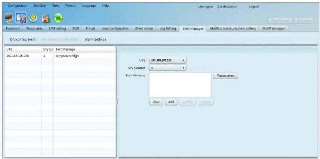
Diagram 5-12
- Alarm Settings: Set up alarm range for temperature and humidity. If detected figures are out of setting range, it will send alarm message. Refer to Diagram 5-13.
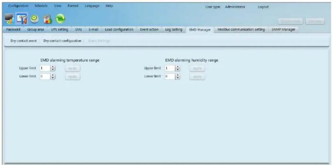
Diagram 5-13
5.8.10. Modbus communication setting
It will display all connected PCs through ModBus.
Step 1 Select configuration>> ModBus Communication Setting. Refer to Diagram 5-14.
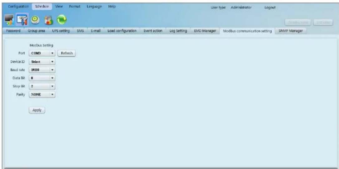
Diagram 5-14
Step 2 Com. port setting:
The default ID for nominated com. port is 0;
➢ Selectable baud rates are 1200, 2400, 4800, 9600, and 19200. The default setting is 19200;
➢ Selectable data bit is 7 and 8. The default setting is 8;
➢ Selectable stop bit is 1 and 2. The default setting is 1;
➢ Supported parity is ODD parity, event parity and NONE. The default setting is NONE.
NOTE: This function is only available for the UPS with ModBus communication port.
5.9. Schedule
5.9.1. Scheduled on/off
Scheduled UPS on/off can be executed once, daily, weekly. Users can select UPS and time parameters. It is recommended to set only one action in the same time. If multiple actions have been applied at the same time, some of these actions may be ignored. Any action will be ignored when the action is not supported by the UPS.
Step 1 Select "Schedule" >> Scheduled on/off. Refer to Diagram 5-15.
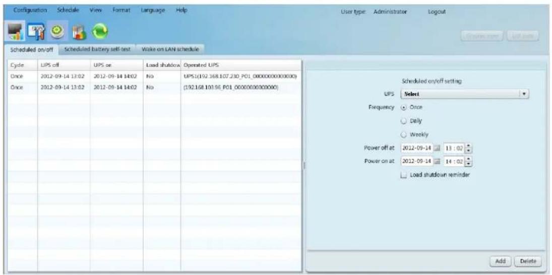
Diagram 5-15
Step 2 Set frequency and setting time on the right column.
NOTE: Please be aware following rules while setting time.
Once - Power-off time should be earlier than power-on time.
Daily schedule – Power-off time should be earlier than power-on time.
Power-on time and power-off time should be set on same day.
Weekly schedule –Power-off time should be earlier than power-on time. Power-on time and power-off time should be within the same week.
Step 3 Click "Add" to add task. If task is successfully set, it will display on the task table on the left-hand side. Select specific task and click "Delete" button to delete the task.
Note 1: If there are same plan in the same time, it will execute only one of them.
Note 2: If the UPS which accepts scheduled on/off setting is connecting with loads, it can also allow to set load shutdown reminder.
5.9.2. Scheduled battery self-test
Scheduled battery self-test can be executed once, daily, weekly, or monthly. Users can select UPS and time parameters. It is recommended to set only one action in the same time. If multiple actions have been applied at the
same time, some of these actions may be ignored. Any action will be ignored when the action is not supported by the UPS.
Select Control >> Battery Self-Test. Refer to Diagram 5-16.
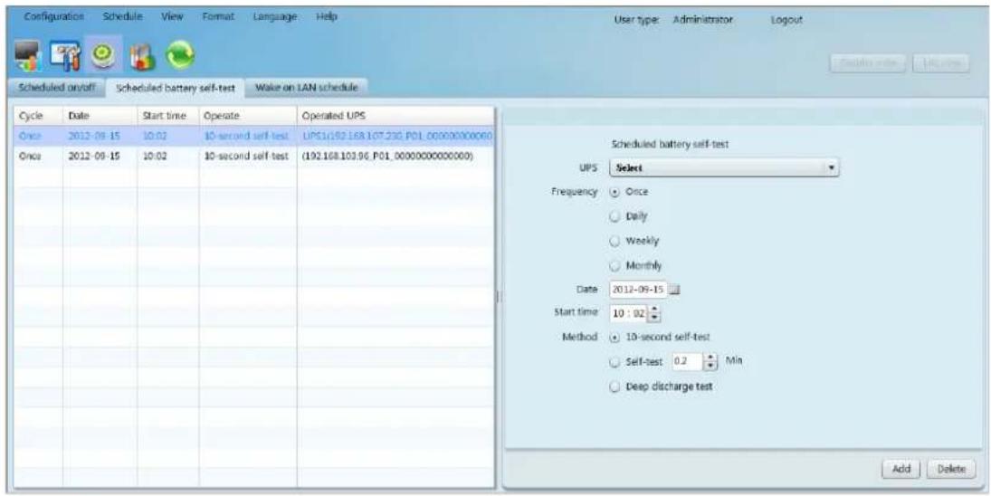
Diagram 5-16
- Select method and time parameters. There are three self-test methods:
➢ 10-second self-test: Battery will discharge for 10 seconds.
➢ Self-test: Users can set battery discharge time for self-test.
Deep test: This test will allow battery to discharge until low battery level.
- Click "Add" to add task. If task is successfully added, it will display on the task table on the left-hand side. Select task from table list and click "Delete" button to delete the task.
5.9.3. Wake on LAN schedule
It supports wake-on-LAN schedule for one or multiple computers at once, daily, and weekly frequency.
- Select Schedule >> Wake on LAN schedule, refer to diagram 5-17:
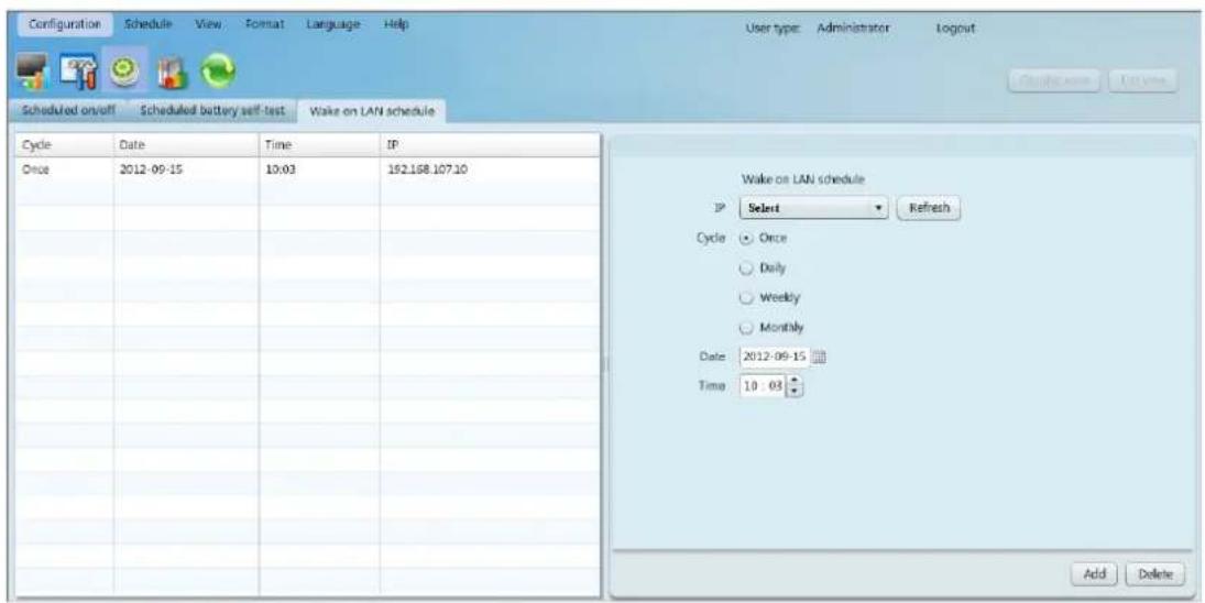
Diagram 5-17
- Select IP, Cycle, Date and Time, and then click "Add" button to add plan.
- Select one plan from schedule list, and then click "Delete" to delete plan.
5.10. View
5.10.1. Centralized monitoring
It includes Text view and Graphic view. Users can exchange view mode by clicking "Text view" button and "Graphic view" button.
✿ Text view: Each UPS is displayed in the panel form and it shows UPS working status and data. Multiple UPSs will be displayed with multiple UPS panels. Refer to diagram 5-18:
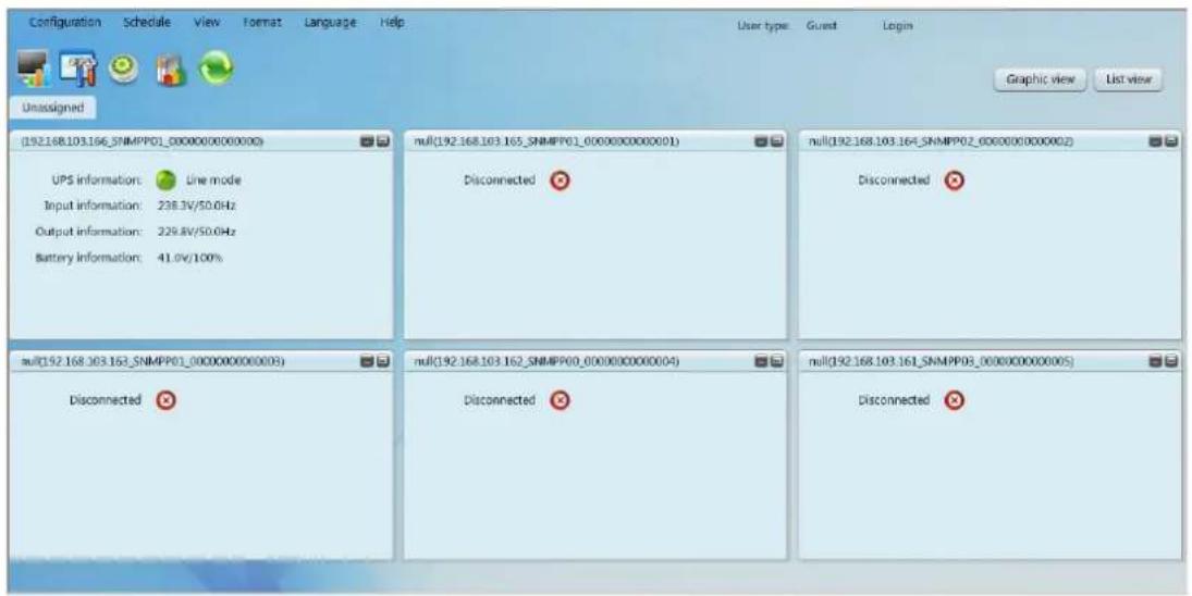
Diagram 5-18
List view: It will show UPS working data and status in a table. Refer to 5-19.
| Configuration | Schedule | View | Format | Language | Help | User type: Guest Login | ||
| Unassigned | Text view Graphic view | |||||||
| UPS | Connection status | UPS information | Input information | Output information | Bypass information | Battery information | ||
| UPS1(192.168.107.230_SNMP01_0000000000000) (192.168.103.96_SNMP01_0000000000000) | Connected | Standby mode | 214.4V/50.0Hz | OV/0.0Hz | 41.0V | |||
| Connected | Line mode | 220.0V/50.0Hz | 229.8V/50.0Hz | 81.2V | ||||
Diagram 5-19
Graphic view: Each UPS is displayed as a simple icon. It shows its status icon with background picture. To avoid any mistakes, it also supports security function. Only when user type is administrator, it's allowed to "unlock" these icons. Then, administrator can drag and drop the icon anywhere freely. The default setting is in "lock" status. Refer to diagram 5-20-a and diagram 5-20-b.
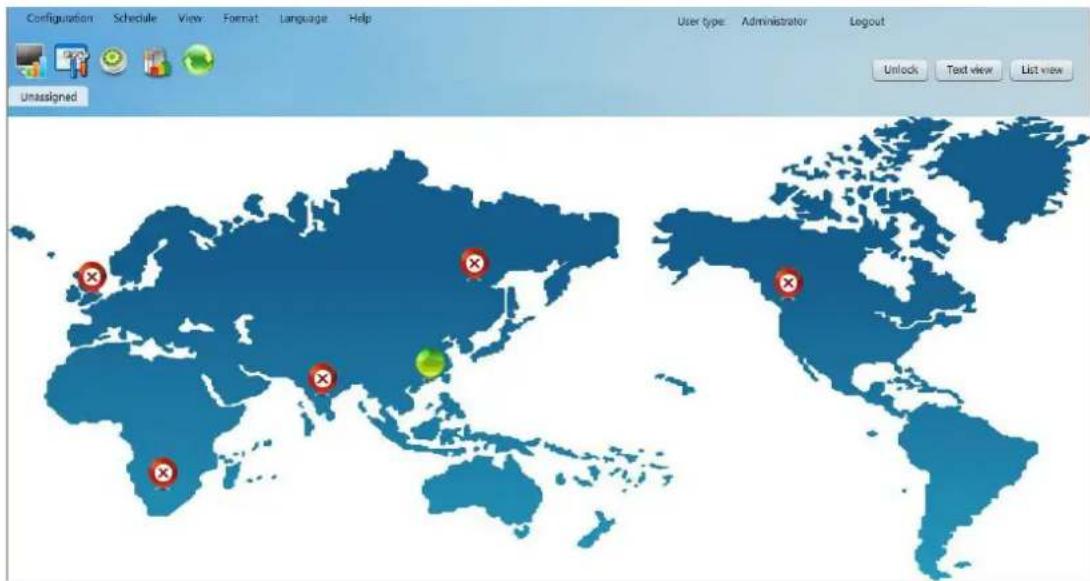
Diagram 5-20-a
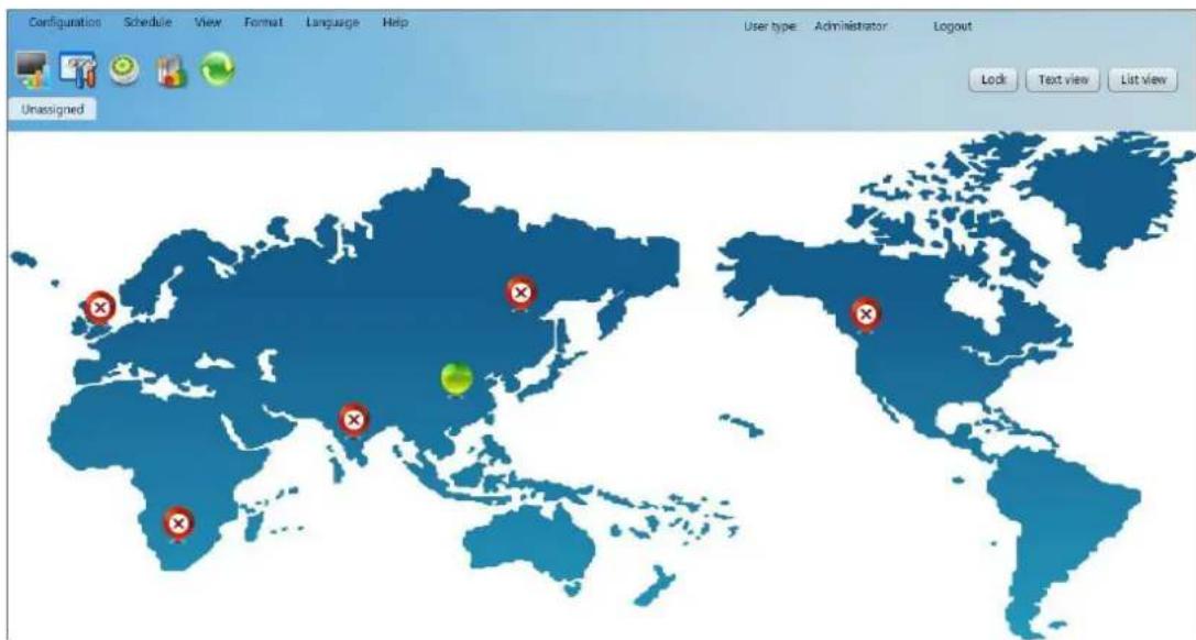
Diagram 5-20-b
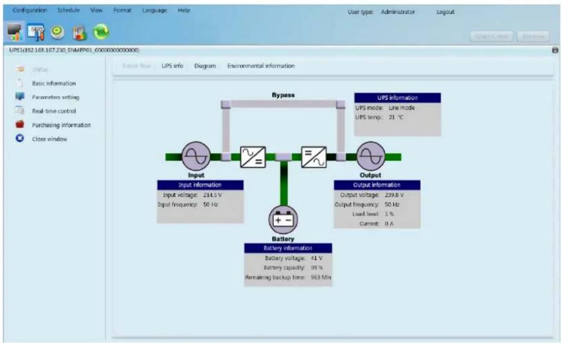
UPS detail information: On the Text view mode, users can enter individual UPS monitoring interface by double clicking each UPS panel. On the Graphic view mode, users can enter individual UPS monitoring interface by double clicking each UPS icon. Refer to diagram 5-21:
flowchart
graph TD
    A["Input"] --> B["Battery"]
    C["Output"] --> B
    B --> D["Bypass"]
    style A fill:#f9f,stroke:#333
    style C fill:#f9f,stroke:#333
    style B fill:#ccf,stroke:#333
Diagram 5-21
5.10.1.1. Status
5.10.1.1.1. Power Flow
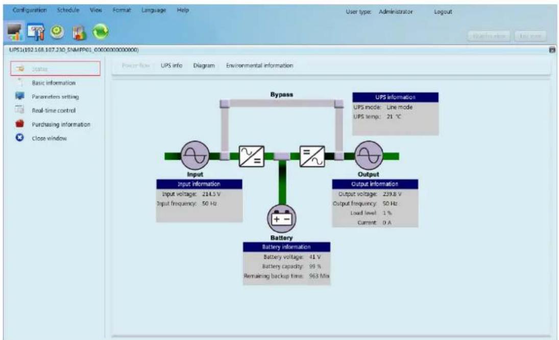
Select Status >> Power Flow. Refer to diagram 5-22. In the Power Flow window, it's shown the internal dynamic working flow of the UPS.
flowchart
graph TD
    A["Input"] --> B["Battery"]
    C["Output"] --> B
    B --> D["Bypass"]
    style A fill:#f9f,stroke:#333
    style C fill:#f9f,stroke:#333
    style B fill:#ccf,stroke:#333
Diagram 5-22
Green/black flow means working well. Grey bar means that the object is
present but not in use at the moment. There are four information blocks to display details about input, output, UPS and battery information.
➢ Input information includes input voltage and input frequency.
Output information includes output voltage, output frequency, load level, and output current.
UPS information includes UPS operation mode and UPS temperature.
Battery information includes battery voltage, battery capacity and remaining backup time.
5.10.1.1.2. UPS Info
Select Status >> UPS Info. Refer to Diagram 5-23.
In the "UPS Info" window, it's shown real-time monitored UPS data including input, output, UPS, and battery information in text and bar.
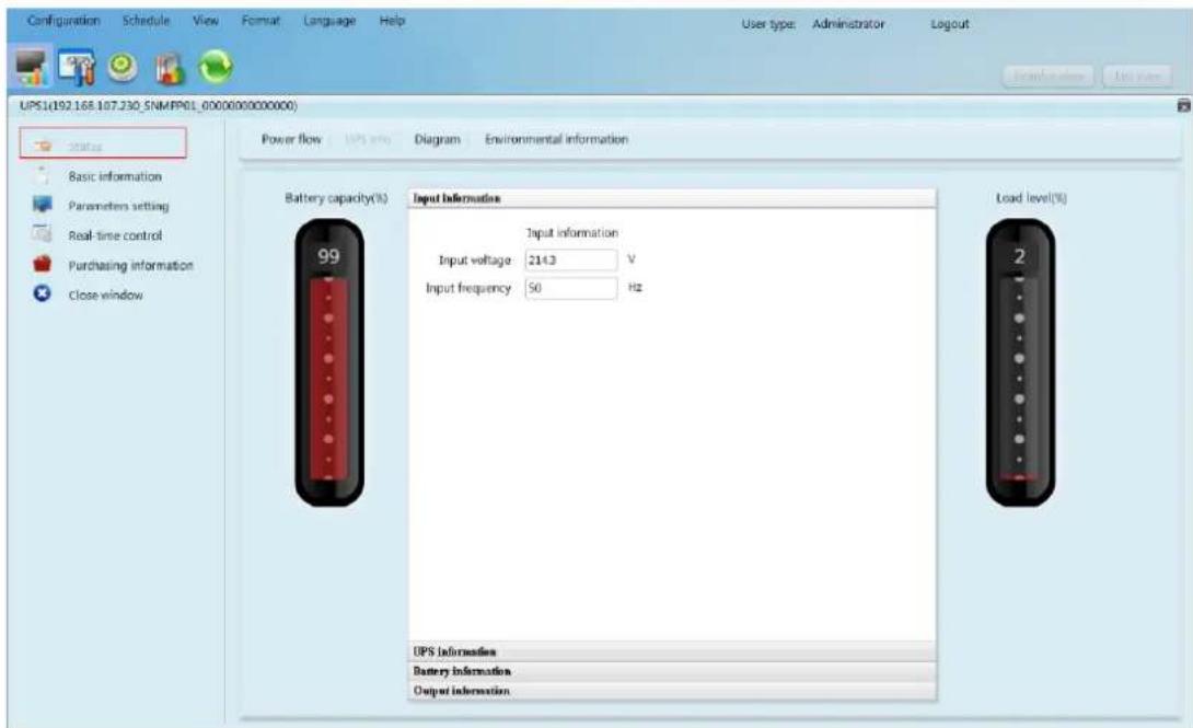
Diagram 5-23
5.10.1.1.3. Diagram
Select View >> Status >> Diagram. Refer to Diagram 5-24.
In the Diagram window, it's shown real-time monitored UPS data including voltage, frequency, load, battery, temperature information in diagram.
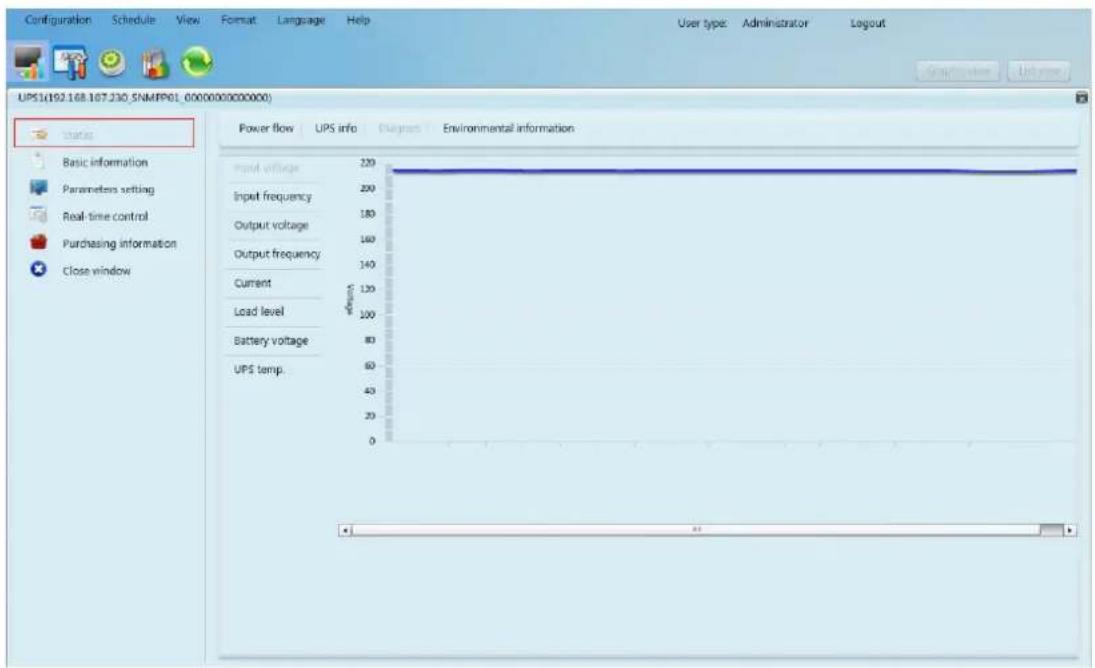
Diagram 5-24
5.10.1.1.4. Environmental information
In the Environmental information window, it shows the current temperature and humidity.
Select Status >> Environmental information. Refer to Diagram 5-25
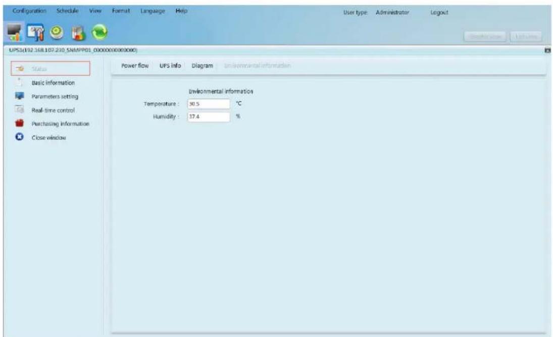
Diagram 5-25
Note: This information is only available when SNMP card is connected with
Environmental monitoring device (EMD).
5.10.1.2. Basic information
It includes UPS basic information, battery information, UPS purchasing information, and UPS rated information. Refer to diagram 5-26.
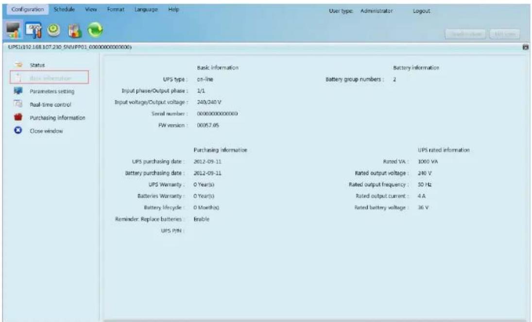
Diagram 5-26
5.10.1.3. Parameters setting
Some UPS functions can be set and changed via software. Parameter setting includes backup time setting for programmable outlet (P1), battery number setting, voltage and frequency range setting for bypass mode, and voltage range setting for ECO mode.
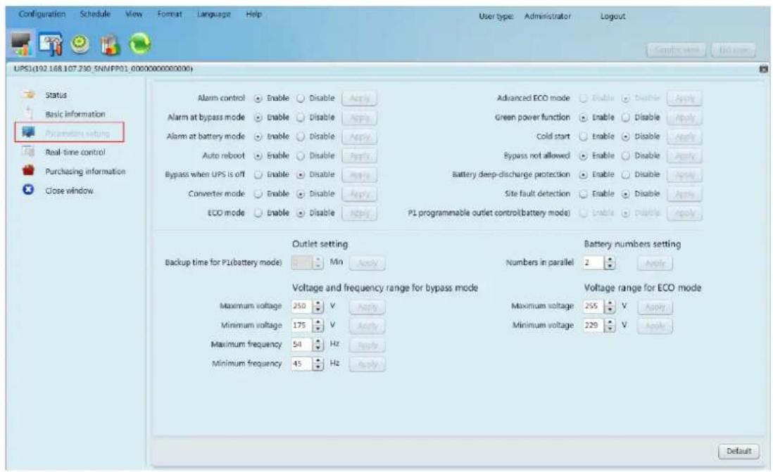
Diagram 5-27
Note: Different UPSs may access different parameter setting.
- Select the functions by clicking "Enable" or "Disable" button. Change the numbers by clicking up-down arrows or modify the numbers directly in the number column.
- Click "Apply" button to save the settings. Each function setting is saved by clicking "Apply" button in each section.
- Click "Default" button to recover the default setting.
Note: Any functions which are not supported by UPS will not be able to access.
➢ Alarm Control: If enabled, UPS alarm will be activated. Vice versa.
Alarm at bypass mode: If enabled, UPS alarms when it's working at bypass mode. Vice versa.
Alarm at battery mode: If disabled, UPS will not alarm when it's working at battery mode. Vice versa.
Auto reboot: If enabled, UPS will auto recover when AC is recovering. Vice versa.
➢ Bypass when UPS is off: If enabled, AC will directly provide power to
connected devices when UPS is off. Vice versa.
➢ Converter mode: If enabled, the UPS will operate in converter mode. Vice versa.
ECO mode: If enabled, the UPS will operate in ECO mode when input voltage is within acceptable range. Vice versa.
Battery open status check: If enabled, the monitored UPS will check if the battery connection ok or not when UPS is turned on.
➢ Cold start: If disabled, the UPS can be turned on only when AC is normally connected to UPS. Vice versa.
Bypass not allowed: If enabled, the UPS will not transfer to bypass mode under any conditions. If disabled, the UPS will be allowed to transfer to bypass mode according to UPS internal setting.
Battery deep-discharge protection: If enabled, the monitored UPS shutdown in accordance with the condition of battery and load on battery mode to protect battery. Vice versa.
Site fault detection: If enabled, the monitored UPS will beep when the input neutral and hot wires are reversed. Vice versa.
P1 Programmable outlet control (battery mode): If enabled, when UPS is running at battery mode, it will cut off P1 outlets after backup setting time arrive. If disabled, UPS will provide continuous power to P1 outlets until the battery is running out.
➢ Outlet setting: Users can set limited backup time for P1 outlets when UPS is on battery mode.
▶ Battery numbers setting:
♦ Numbers in parallel: set battery numbers in parallel
➢ Voltage and frequency range for bypass mode: Set acceptable voltage and frequency range in bypass mode
Maximum and minimum voltage: When UPS is on bypass mode and input voltage is out of setting range, UPS will enter battery mode.
✿ Maximum and minimum frequency: When UPS is on bypass mode
and input frequency is out of setting range, UPS will enter battery mode.
Voltage range for ECO mode: Set acceptable voltage range for ECO mode.
5.10.1.4. Real-time control
Refer to diagram 5-28:
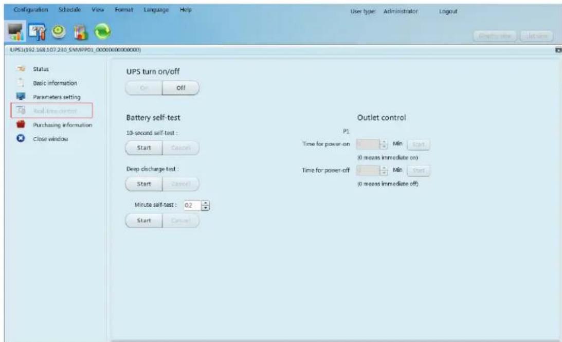
Diagram 5-28
- Choose real-time control function by clicking "Start" button on each function section. You can real-time control the UPS by executing following operation:
UPS turn On/Off: Click "On" to turn on the UPS and "Off" to turn off the UPS immediately.
Battery Self-Test: Software offers three types of battery self-test: 10-second self-test, deep discharge test, and self-defined self-test. Simply clicking "Start" button from each type. It will execute the self-test immediately.
Outlet Control: It will cut off programmable outlets (P1) when setting time arrives. When entering 0 in timer column and click
"Start" button, it will cut off outlets immediately when UPS works in battery mode.
Note: Different UPSs may access different parameter setting.
5.10.1.5. Purchasing information
Users can enter UPS purchasing date, battery purchasing date, UPS warranty time, battery warranty time, battery lifecycle, and battery replacement reminder for future reference.
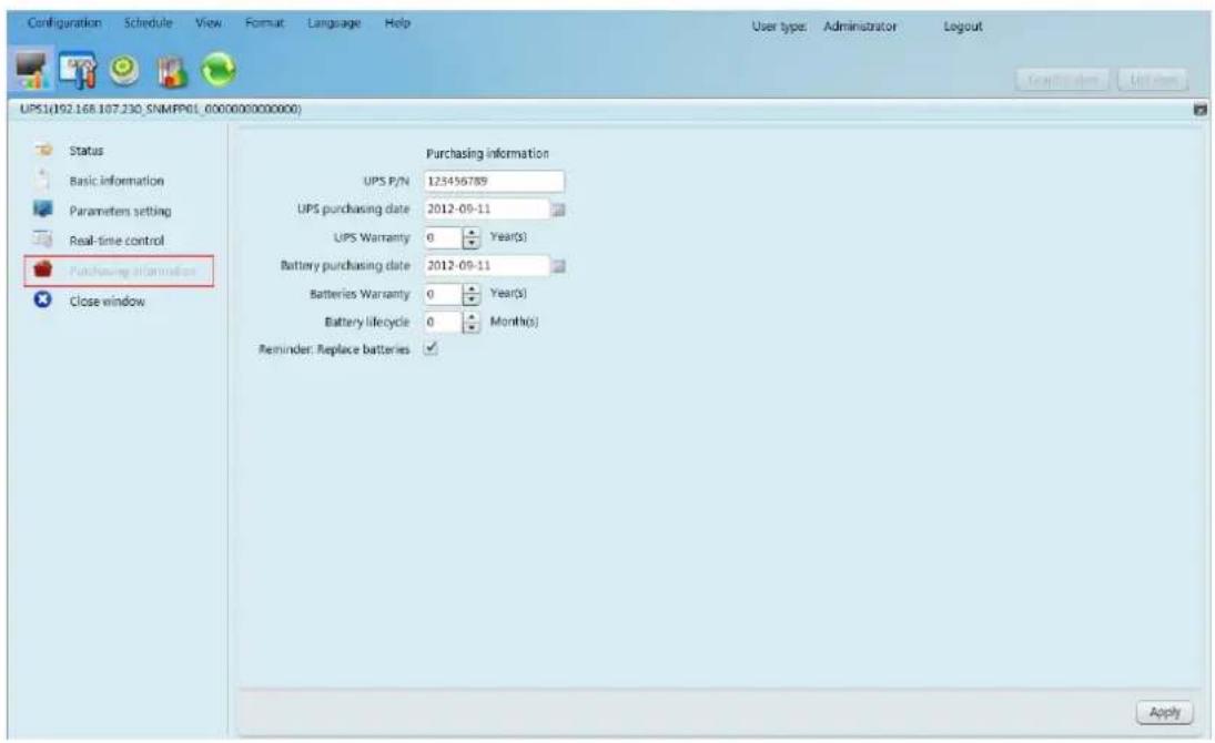
Diagram 5-29
-
Please fill out purchasing information.
-
Click "Apply" button to save all data.
5.10.2. History
5.3.2.1. Event Log
In the Event Log window, it's shown all history events. Users can analyze the history data and improve the current electricity environment according to history data.
- Select View >> History >> Event Log. Refer to Diagram 5-30
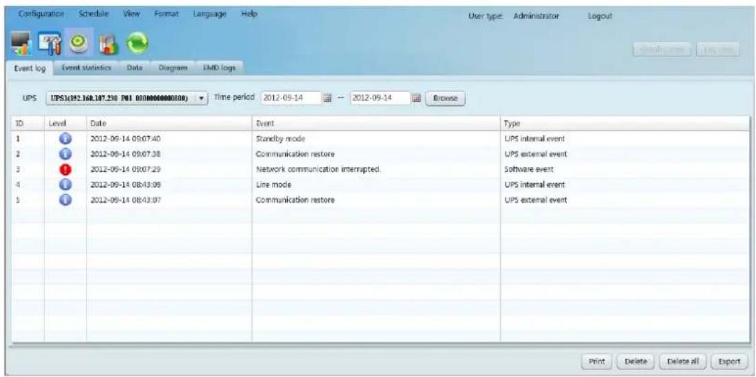
Diagram 5-30
- Select UPS from com. port list. Users still can retrieve old data saved in the software even though the UPS is no longer connected to local system.
- Select time period by clicking calendar icon. Then click "Browse" button to get list of all history events during selected period time.
- Print/Delete/Export function keys
"Print": Click "Print" button to print the current event log.
"Delete/Delete all": To delete specific event, simply select that event and then click "Delete" button. Or click "Delete all" button to delete all history events on the listed table.
"Export": Click "Export" button to save listed table to local PC in .CSV file.
5.3.2.2. Event Statistics
It will list down and provide all event statistics for UPSs with software installed based on time period A and time period B, and the change percentage [= 100*(B/A - 1)%] .
NOTE: Event types include UPS internal event, bypass event, battery event, software event, load event, input event, parallel system event and communication event.
Step 1 Select History >> Event Statistics. Or click shortcut icon. Refer to Diagram 5-31.

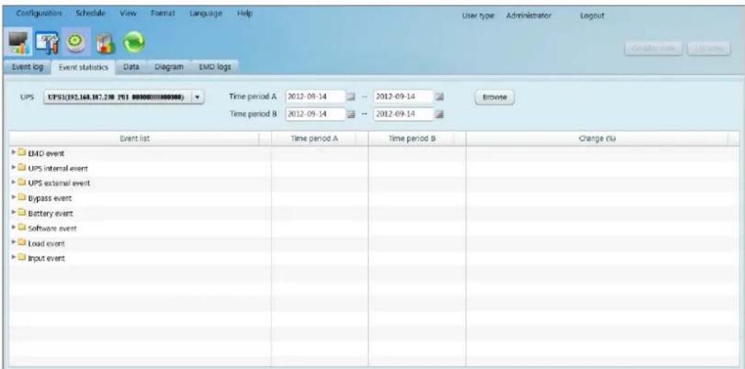
Diagram 5-31
Step 2 Select UPS from com. port list. Users still can retrieve old data saved in the software even though the UPS is no longer connected to local system.
Step 3 Select two periods from clicking "calendar" icon. Then click "Browse" button. The statistics result will be listed in below table according to event types. Refer to Diagram 5-32.
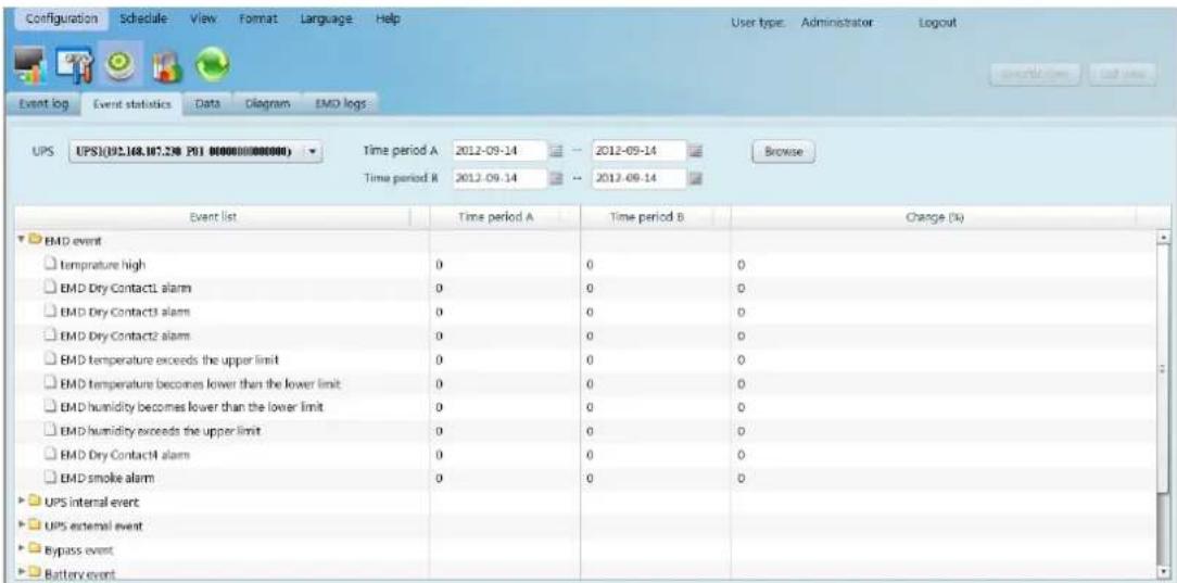
Diagram 5-32
Click "Print" button to print event statistics.
5.3.2.3. Data
In the window of Data, it shows UPS power data in figures during selected period time. Software also offers print, save as, and delete functions. User can customize record interval and default data is recorded in 60 seconds interval.
Step 1 Select View >> History >> Data. Refer to Diagram 5-33.
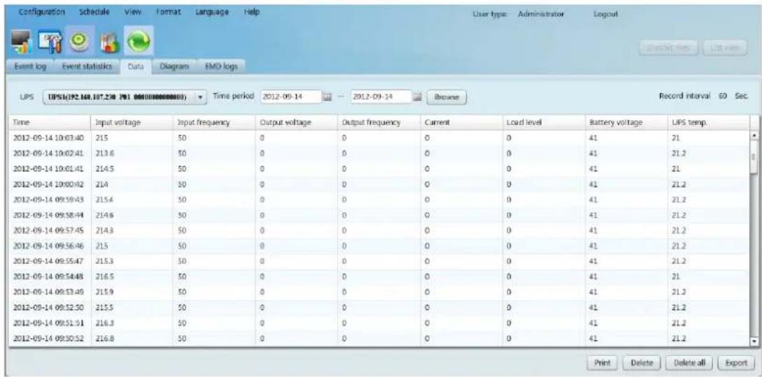
Diagram 5-33
NOTE: This screen may be different for different types of UPSs.
Step 2 Select UPS from com. port list. Users still can retrieve old data saved in the software even though the UPS is no longer connected to local system.
Step 3 Select the starting time and ending time by clicking calendar icon. Then click "Browse" button to get the data table.
"Print": Print the listed data table.
➢ "Delete": Select specific data and click "Delete" button to delete the record.
"Delete all": Click "Delete all" button to delete all records on the listed table.
"Export": Click "Export" button to save listed table to local PC in .CSV file.
5.3.2.4 Diagram
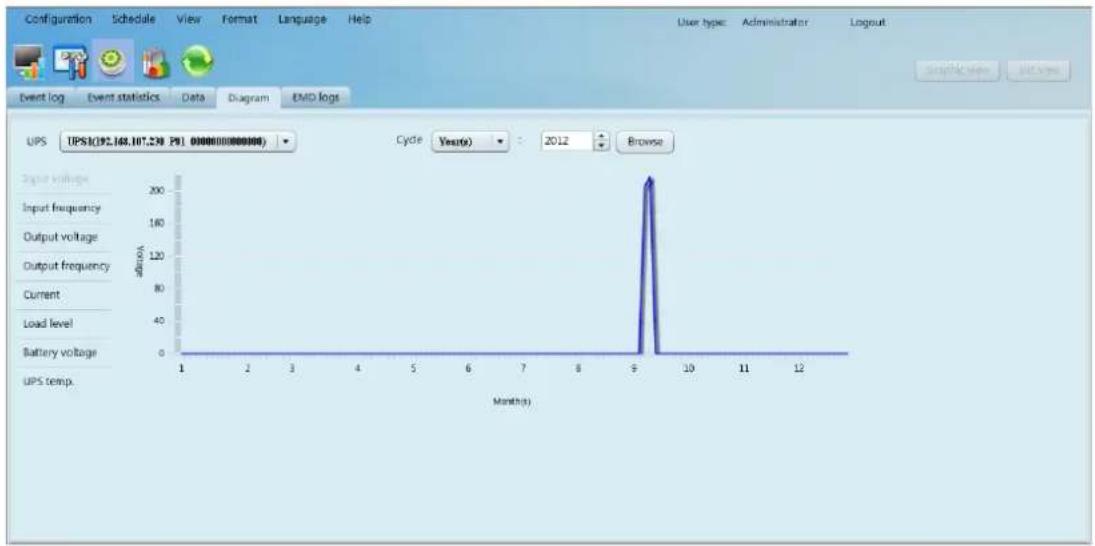
In the Diagram window, it shows UPS power data in diagram during selected period time. UPS power data includes input voltage, output voltage, input frequency, output frequency, load level, battery capacity, and UPS temperature.
Step 1 Select View >> History >> Diagram. Refer to Diagram 5-34.
line
| Month(s) | Voltage | | -------- | ------- | | 9 | 200 |Diagram 5-34
NOTE: This screen may be different for different types of UPSs.
Step 2 Select UPS from com. port list. Users still can retrieve old data saved in the software even though the UPS is no longer connected to local system.
Step 3 Select cycle and period time. Then click "Browse" button to get the diagram.
Step 4 Select monitoring parameters on left-hand tab to switch diagram.
5.3.2.4. EMD Logs
In the EMD logs window, it shows the environment data in figures detected by environmental monitoring device (EMD) during selected period time.
Step 1 Select View >> History >> EMD logs. Refer to Diagram 5-35.
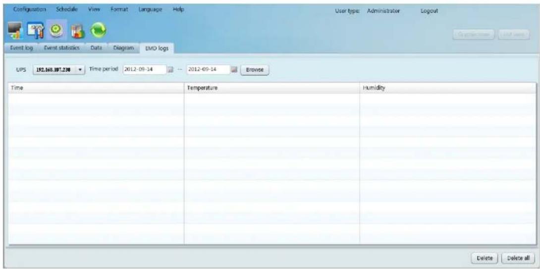
Diagram 5-35
Step 2 Select UPS and select the starting time and ending time by clicking calendar icon. Then click "Browse" button to get the data table. Delete/Delete all
"Delete": Select specific data and click "Delete" button to delete the record.
"Delete all": Click "Delete all" button to delete all records on the listed table.
5.11. Format
5.11.1. Temperature Unit
There are two temperature units for selecting: Centigrade and Fahrenheit. Default setting is centigrade.
5.11.2. Date Format
There are nine formats for date display:
YYYY-MM-DD
YYYY/MM/DD
YYYY:MM:DD
MM-DD-YYYY
MM/DD/YYYY
MM:DD:YYYY
ViewPower Pro offers thirteen languages for selection:
English
French
German
Italian
Polish
Portuguese
▶ Russian
▶ Spanish
Ukrainian
▶ Turkish
Czech
Chinese(Simplified)
Chinese(Traditional)
5.13. Help
5.13.1. About
Click "Help" menu and select "About". It represents the information about software.
5.13.2. Online help
Click "Help" menu and select "Online help" item. It will open user manual.
Before operating software, please read manual carefully.
- Service Tray Application....11
- Configuration....24
- ViewPower Pro GUI 30
- ViewPower Pro Menu....31
- Configuration....31
- Schedule 43
- View 46
- Format....61
- Language....62
- Help....62
- ViewPower Pro Overview
- Introduction
- Structure
- Features
- ViewPower Pro Install and Uninstall
- System requirement
- Software Install
- Diagram 2-1
- Software Uninstall
- Service Tray Application
- Start Monitor
- Stop Monitor
- SNMP Manager
- Output window displays all messages for operations
- SNMP Device List
- Scan
- Add
- Delete
- SNMP Status
- Reset
- Use system time
- Function Menu
- System
- Login
- Logout
- Quit
- Settings
- Basic Info
- Online upgrade
- Static trap address
- Language
- Configuration
- Https/Http
- ViewPower Pro Start and Exit Setting
- Software Upgrades
- upgrade:
- Configuration Saved
- Https
- Software Update
- Open Monitor
- Exit
- ViewPower Pro GUI
- ViewPower Pro Menu
- Configuration
- Password Setting
- Group area
- UPS setting
- ▶ Query
- Modify
- SMS
- Load configuration
- Event action
- Diagram 5-9
- Log setting
- EMD Manager
- Modbus communication setting
- Step 2 Com. port setting:
- Schedule
- Scheduled on/off
- Scheduled battery self-test
- Wake on LAN schedule
- View
- Centralized monitoring
- Status
- Power Flow
- UPS Info
- Diagram
- Environmental information
- Basic information
- Parameters setting
- Real-time control
- Purchasing information
- History
- Event Log
- Event Statistics
- Data
- Diagram
- EMD Logs
- Format
- Temperature Unit
- Date Format
- Help
- About
- Online help
Brand : ATEN
Model : SP100
Category : Uncategorized