
KD-WP8-3 - Router Key Digital - Free user manual and instructions
Find the device manual for free KD-WP8-3 Key Digital in PDF.

| Product Type | Network Router / AV over IP Transceiver |
| Dimensions (W x D x H) | 5.5 x 3.5 x 1.2 inches (140 x 89 x 30 mm) |
| Weight | 0.5 lbs (230 g) |
| Power Supply | 5V DC, 2A (included) |
| Ethernet Ports | 3x Gigabit Ethernet (1 WAN, 2 LAN) |
| Wireless Standard | 802.11ac (Wi-Fi 5) dual-band |
| Max Wireless Speed | 1200 Mbps (300 Mbps 2.4GHz + 867 Mbps 5GHz) |
| Antenna Type | 2 internal antennas |
| VPN Support | OpenVPN, PPTP, L2TP |
| Security Features | WPA2-PSK, WPA3, SPI Firewall, DoS protection |
| Frequency Band | 2.4 GHz / 5 GHz |
| Setup and Management | Web interface, mobile app (iOS/Android) |
| Operating Temperature | 32°F to 104°F (0°C to 40°C) |
| Storage Temperature | -4°F to 158°F (-20°C to 70°C) |
| Humidity | 10% to 90% non-condensing |
| Certifications | FCC, CE, RoHS |
| Maintenance and Cleaning | Unplug before cleaning; use a dry cloth; avoid liquids |
| Spare Parts and Repairability | No user-serviceable parts; contact Key Digital support for service |
| General Information | Designed for reliable home and small office networking |
Frequently Asked Questions - KD-WP8-3 Key Digital
User questions about KD-WP8-3 Key Digital
0 question about this device. Answer the ones you know or ask your own.
Ask a new question about this device
Download the instructions for your Router in PDF format for free! Find your manual KD-WP8-3 - Key Digital and take your electronic device back in hand. On this page are published all the documents necessary for the use of your device. KD-WP8-3 by Key Digital.
USER MANUAL KD-WP8-3 Key Digital
Setup & Programming Guide KD-WP8-3
8 Button Programmable IP, IR, RS232 Wall Plate Control Keypad with PoE for KDPlug & Present™, Compass Control® Pro, and Third-Party Systems via Open API

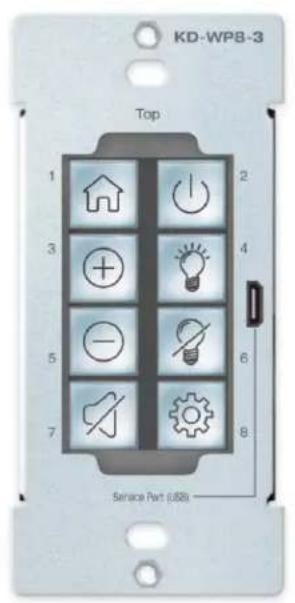
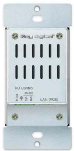
Table of Contents
ABOUT KD-WP8-3....3
APPLICATION DIAGRAMS 4
QUICK SETUP GUIDE 6
- BUTTON CAPS....6
- CONNECT ....7
- CONFIGURE....8
• COMMON BUTTON & EVENT EXAMPLES ....30
CONTROL....36
• INSTALLATION IN GANG BOX....38
LED INDICATOR TABLE 41
TCP/IP CONTROL COMMANDS 40
IR & RS232 PORT INFO....41
KD-WP8-3 IN COMPASS CONTROL PRO SYSTEMS 42
OPEN API CONTROL OF IR & RS232 PORTS....44
SPECIFICATIONS 45
WARRANTY INFORMATION 49
PRODUCT WARNINGS & SAFETY INSTRUCTIONS....47

Default IP Address: 192.168.1.239
Quick Setup Guide
Please visit www.keydigital.com for the latest product documentation, firmware, control drivers and software downloads. Product features and specifications are subject to change without notice
Always follow the instructions provided in this Operating Manual.
Accessories
• Qty 1: 6ft USB A to USB micro cable
• Qty 1: Brushed aluminum decora plate
• Qty 4: Decora and box mounting screws
• Qty 10: Inner button caps
• Qty 10: Outer buttons caps (clear)
• Qty 1: Flathead mini screwdriver
• Qty 1: Set button icon sheet
• Qty 1: IR Emitter, 6ft
About KD-WP8-3
Key Digital® KD-WP8-3 is an eight-button single-gang sized control keypad that is PoE powered. KD-WP8-3 is easily programmed via web GUI to send commands over the network to IP controlled devices or via the built-in RS232 and IR control ports. KD-WP8-3 may also be integrated with Key Digital Master Controllers to control additional IR, RS232 and voltage relay devices. Button events may be configured on the press, release, toggle, or press & hold action as desired. Along with selectable blue or red backlighting, KD-WP8-3 includes multiple transparent icon sheets that are simply inserted beneath transparent button caps for a modern and professional appearance. The keypad supports key combo lock & unlock and virtual keypad via password protected web UI, Key Digital Management PC Software, and KD-App. Completed project files may be exported and imported for programming time reduction and rollout of multiple keypads in cookie-cutter installations. KD-WP8-3's simplistic open API makes for easy two-way integration with professional control systems.
Key Features
- PoE Powered: Installs cleanly with PoE network switch or PoE injector (not included).
- Single-Gang: Fits U.S. single-gang wall box. Brushed aluminum decora plate included.
- Ease of Programming: Web GUI walkthrough of network settings, project import & export, button configuration, event programming and virtual event keypad access.
- IP Controller: Natively sends TCP, UDP, and Telnet commands in ASCII or HEX format for controlling IP devices without any additional hardware needed.
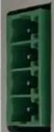
• Built-In RS232 and IR: One native RS232 and IR port on 5-pin phoenix connector - IR, RS232, and Relay Control: Add KD-CX800, KD-MC1000, or KD-IP822/922/1022 master controllers for control of additional IR, RS232, or voltage relay devices.
- Multi-Controller Support: Integrate with any number of KD Master Controllers
- Point-to-Point Support: Direct connect network cabling from KD-WP8-3 to PoE injector and Master Controller for installation without network setup hassle.
- RS232 Command Strings: ASCII or HEX formats supported. Baud rate from 1,200 to 115,200 bps.
- IR Command Strings: Copy & paste Pronto Hex or Compass Control IR burst data.
- Variable Support: Up to 8 integer variables may be utilized to store values for sending in commands.
- 160 Events Possible: Up to 10 commands on button press and release/repeat, for up to 20 events per button and 160 events total.
- Key Combo Security: Two-button press combo and auto lock setting may be applied to lock & unlock keypad.
- Virtual Keypads: Password protected web GUI with user-friendly minimal layout or Programmer-friendly layout with transmit & receive logs.
- KDMS Pro and KD-App Ready: Virtual keypad GUI options accessed by PC software and iOS app.
- Button Configuration: Red or blue LED backlighting, normal or toggle button types, press event, release event, hold for repeat, and hold for send options.
- Detachable Button Caps: 10 inner button caps, 10 outer button caps, and flathead mini screwdriver included.
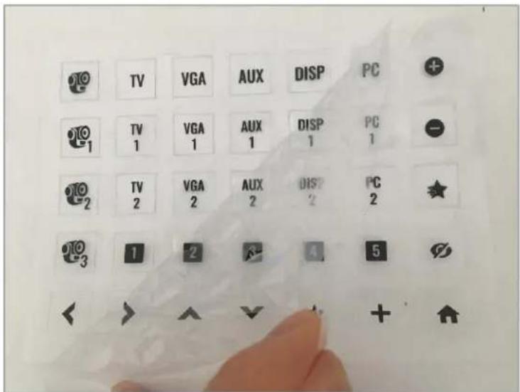
- Icon Sheets: 175 transparent icons provided. Template available for custom printing.
- Open API: Simple two-way communication protocol for IP integration with control systems.
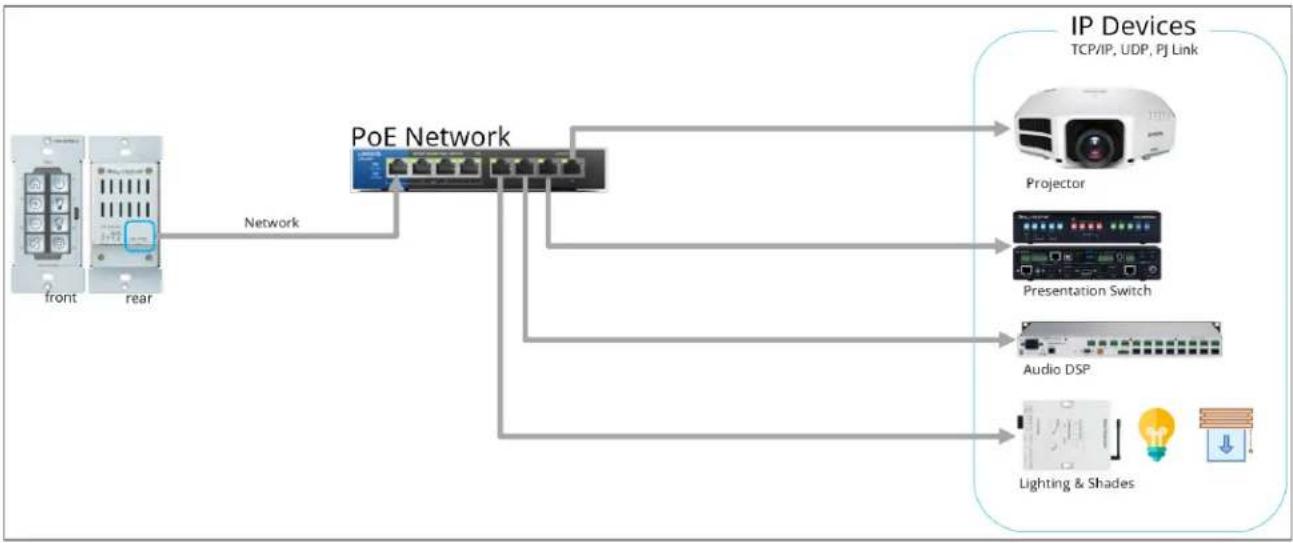
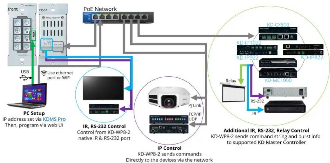
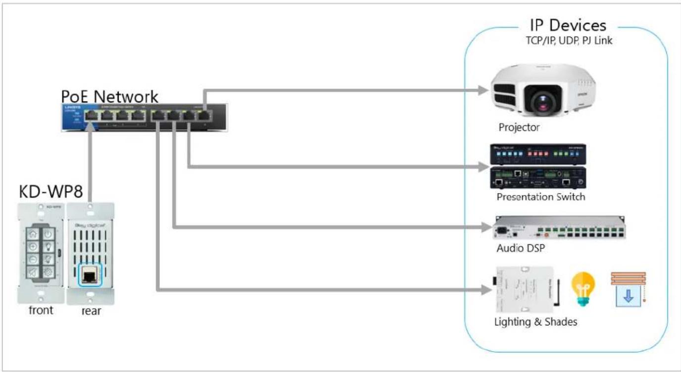
Application Diagrams
KD-WP8-3 IP Device Control: KD-WP8-3 sends commands directly to the devices via the network.
flowchart
graph LR
    A["Front"] -->|Network| B["PoE Network"]
    C["rear"] -->|Network| B
    B --> D["Projector"]
    B --> E["Presentation Switch"]
    B --> F["Audio DSP"]
    B --> G["Lighting & Shades"]
    D --> H["IP Devices TCP/IP, UDP, PJ Link"]
    E --> H
    F --> H
    G --> H
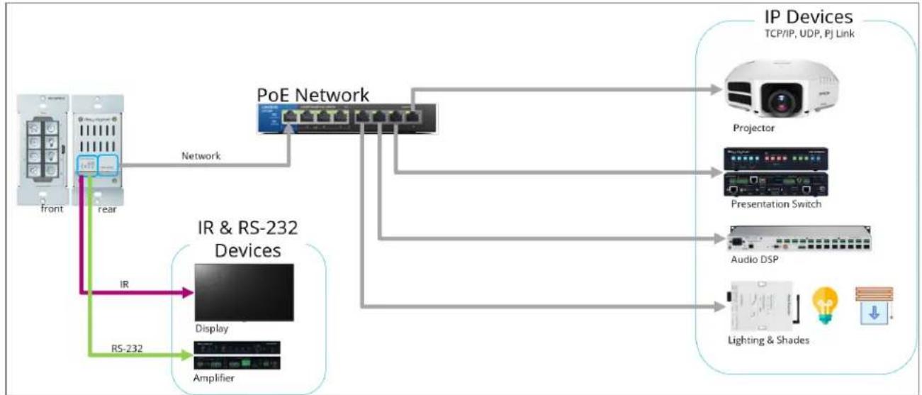
KD-WP8-3 Built-In Control: KD-WP8-3 controls 1 IR and 1 RS232 device via 4pin Phoenix on rear. For IP control, KD-WP8-3 sends commands directly to the devices via the network.
flowchart
graph TD
    A["Front"] -->|IR| B["Display"]
    A -->|RS-232| C["Amplifier"]
    A -->|rear| D["Network"]
    D --> E["PoE Network"]
    E --> F["Projection"]
    E --> G["Presentation Switch"]
    E --> H["Audio DSP"]
    E --> I["Lighting & Shades"]
    E --> J["IP Devices TCP/IP, UDP, PJ Link"]
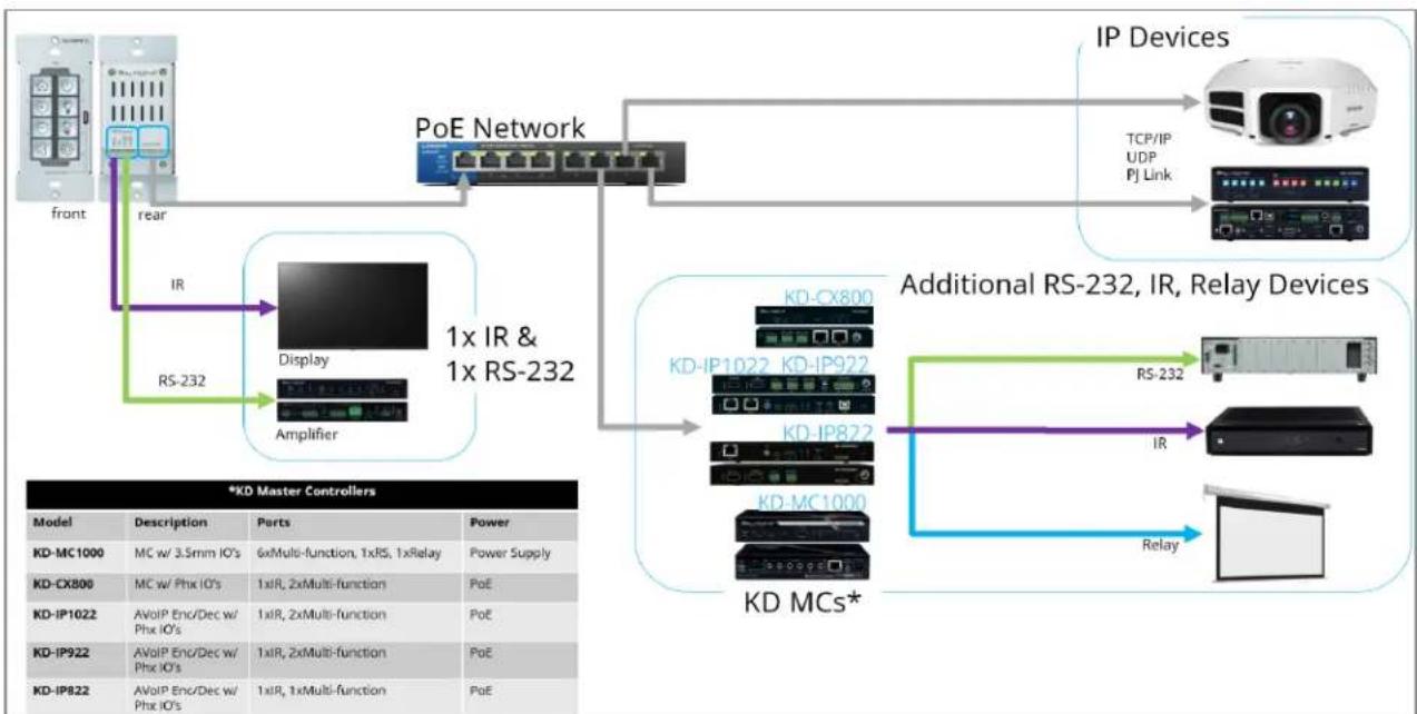
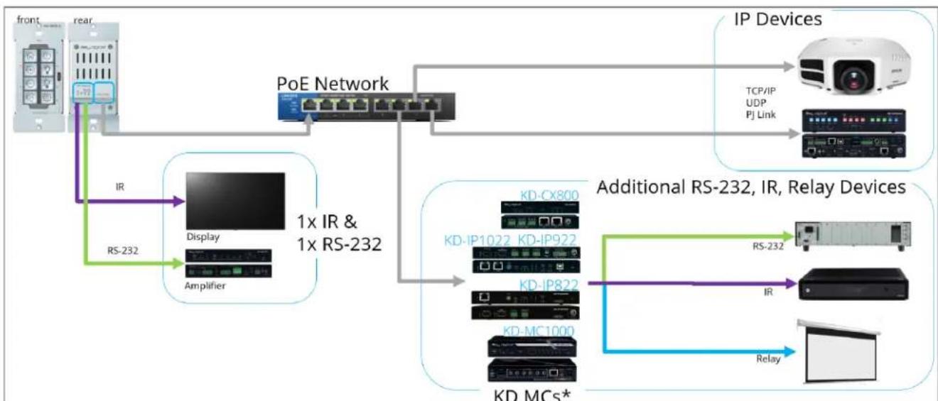
Additional IP, IR, RS, Relay Control: KD-WP8-3 controls 1 IR and 1 RS232 device via 4-pin Phoenix port. For IP control, KD-WP8-3 sends commands directly to the devices via the network. For additional IR, RS232, and Relay control, KD-WP8-3 sends command string and burst info to supported KD Master Controller.
flowchart
graph TD
    A["Front"] --> B["PoE Network"]
    B --> C["IP Devices"]
    C --> D["TCP/IP UDP PJ Link"]
    B --> E["Additional RS-232, IR, Relay Devices"]
    E --> F["KD-MCS*"]
    F --> G["Relay"]
    H["Rear"] --> I["Display Amplifier"]
    I --> J["1x IR & 1x RS-232"]
    K["IR"] --> I
    L["RS-232"] --> I
    M["*KD Master Controllers"] --> N["Model"]
    N --> O["Description"]
    O --> P["Parts"]
    P --> Q["Power"]
    R["KD-MC1000"] --> S["MC w/ 3.5mm IO's"]
    T["KD-CX800"] --> U["MC w/ Phx IO's"]
    V["KD-IP1022"] --> W["AVoIP Enc/Dec w/ Phx IO's"]
    X["KD-IP922"] --> Y["AVoIP Enc/Dec w/ Phx IO's"]
    Z["KD-IP822"] --> AA["AVoIP Enc/Dec w/ Phx IO's"]
    AB["Additional RS-232, IR, Relay Devices"] --> AC["RD-CPX800"]
    AC --> AD["KD-IP1022 KD-IP922"]
    AD --> AE["KD-IP822"]
    AE --> AF["KD-MC1000"]
    AF --> AG["RD-CPX800"]
    AG --> AH["KD-IP1022 KD-IP922"]
    AI["Additional RS-232, IR, Relay Devices"] --> AJ["RD-CPX800"]
    AJ --> AK["KD-IP1022 KD-IP922"]
    AL["Additional RS-232, IR, Relay Devices"] --> AM["KD-MCS*"]
    AM --> AN["RD-CPX800"]
    AN --> AO["KD-IP822"]
    AP["Additional RS-232, IR, Relay Devices"] --> AQ["KD-MCS*"]
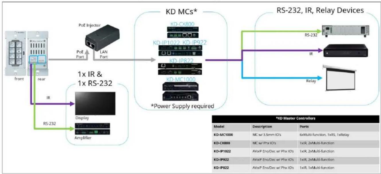
No network switch Required: KD-WP8-3 is powered by PoE Injector with connectivity to Master Controller. KD-WP8-3 controls 1 IR and 1 RS232 device via 4-pin Phoenix port. For additional IR, RS232, and Relay control, KD-WP8-3 sends command string and burst info to supported KD Master Controller
flowchart
graph TD
    A["Front"] -->|PoE Port| B["1x IR & 1x RS-232"]
    B -->|RS-232| C["Display Amplifier"]
    C --> D["Amplifier"]
    D --> E["PoE Injector"]
    E --> F["LAN Port"]
    F --> G["KD MCs*"]
    G --> H["KD-IP1022_KD-IP922"]
    G --> I["KD-IP822"]
    G --> J["KD-MC1000"]
    G --> K["*Power Supply required"]
    K --> L["Relay Devices"]
    L --> M["RS-232"]
    M --> N["IR"]
    N --> O["Relay Device"]
Quick Setup Guide
Button Caps
PPT or PDF icon sheets (including blank spaces and font info) may be downloaded for custom printing.
- Remove the desired button icons from the provided sheets.
- Place icon piece on top of inner button cap (white).
-
Place outer button cap (clear) on top of inner button cap. Ensure the icon placement is still centered.
a. IMPORTANT: Tab and slot must be oriented on Left and Right sides of button. -
Place button onto desired space on KD-WP8-3 with light downward pressure until button clicks into place.
a. Ensure the button placement corresponds with button numbering (1-8) as programmed.
-
If needed, buttons may be removed using the provided mini flathead screwdriver to gently pry on the outer left or right side.
-
Install KD-WP8-3 and decora plate into wall box after all programming is confirmed.
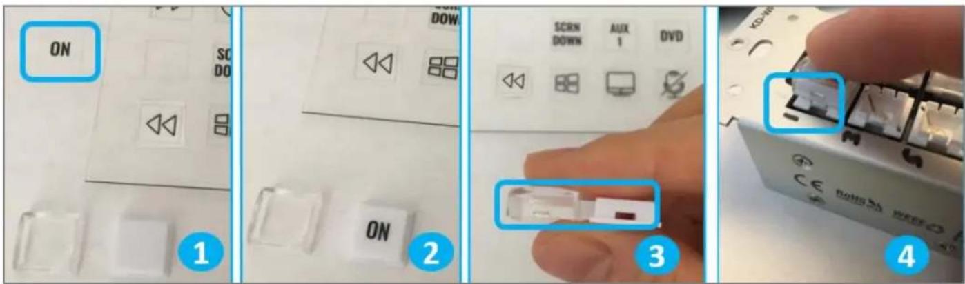

Note: Peel protective film from icon sheet before removing button icons.
Connect
- Connect KD-WP8-3 to PoE providing network switch or PoE injector.
- Connect USB cable from service port into programming PC. This will be used for initial setup of desired IP address.
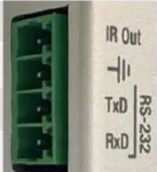
- For IR control, use the included IR emitter according to the below pinout.
- For RS232 control, use an RS232 cable (not included) with stripped wire ends and insert according to below pinout. For ease of installation, a pre-stripped cable with pinout documented by the manufacturer is recommended. Example
| Keypad Pin # | Signal | Cable on KD Accessory | ||
 | IR Out | 1 | IR Out | Striped wire on KD IR Emitter |
| -II | 2 | Ground (shared by IR and RS-232) | Solid wire on KD IR Emitter | |
| TxD -232 \ RXD . | 3 | RS-232 TxD | (not included) | |
| 4 | RS-232 RxD | (not included) | ||
- If controlling additional IR, RS232 or voltage relay devices, add KD-CX800, KD-MC1000, or KD AVoIP Encoders/Decoders with built-in Master Controller functionality to network.
Connectivity Example for Setup & Installation
flowchart
graph TD
    A["front"] -->|USB| B["PC Setup"]
    B --> C["IP address set via KDMS Pro Then, program via web UI"]
    C --> D["rear"]
    D --> E["PoE Network"]
    E --> F["Additional IR, RS-232, Relay Control"]
    F --> G["PD"]
    G --> H["Relay"]
    H --> I["PD-CPX800"]
    H --> J["PD-IP1022"]
    H --> K["PD-IP922"]
    H --> L["PD-MC1000"]
    H --> M["RD-CPX800"]
    H --> N["RD-IP1022"]
    H --> O["RD-IP922"]
    H --> P["RD-MC1000"]
    H --> Q["RD-CPX800"]
    H --> R["RD-IP1022"]
    H --> S["RD-IP922"]
    H --> T["RD-MC1000"]
    H --> U["RD-CPX800"]
    H --> V["RD-IP1022"]
    H --> W["RD-IP922"]
    H --> X["RD-MC1000"]
    H --> Y["RD-CPX800"]
    H --> Z["RD-IP1022"]
    H --> AA["RD-IP922"]
    H --> AB["RD-MC1000"]
    H --> AC["RD-CPX800"]
    H --> AD["RD-IP1022"]
    H --> AE["RD-IP922"]
    H --> AF["RD-MC1000"]
    H --> AG["RD-CPX800"]
    H --> AH["RD-IP1022"]
    H --> AI["RD-IP922"]
    H --> AJ["RD-MC1000"]
    H --> AK["RD-CPX800"]
    H --> AL["RD-IP1022"]
    H --> AM["RD-IP922"]
    H --> AN["RD-MC1000"]
    H --> AO["RD-CPX800"]
    H --> AP["RD-IP1022"]
    H --> AQ["RD-IP922"]
    H --> AR["RD-MC1000"]
    H --> AS["RD-CPX800"]
    H --> AT["RD-IP1022"]
    H --> AU["RD-IP922"]
    H --> AV["RD-MC1000"]
    H --> AW["RD-CPX800"]
    H --> AX["RD-IP1022"]
    H --> AY["RD-IP922"]
    H --> AZ["RD-MC1000"]
    H --> BA["RD-CPX800"]
Configure
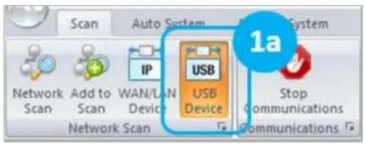
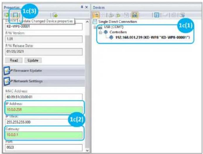
1. Set the desired IP Address and Control Mode via KDMS Pro
a. Open KDMS Pro software and perform a USB Scan, ensuring that KD-WP8-3 is connected to PC via USB cable.
b. Select YES, when asked if your device is a Master Controller.
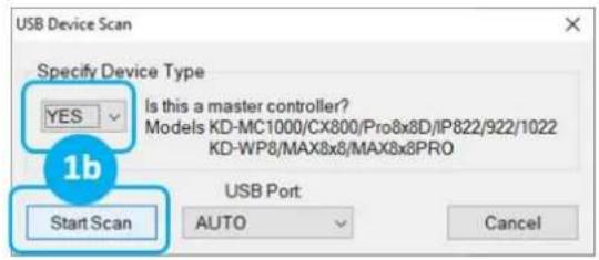
c. (1) Select the KD-WP8-3, (2) enter the desired IP settings, (3) press SAVE disc to update settings, and wait for unit to reboot.
d. Select the desired Control Mode of the KD-WP8-3
i. Standard / Compass (default): KD-WP8-3 executes commands as programmed in web UI. IR & RS232 ports may execute commands as programmed in web UI or in Compass Control. This is the most common mode of use.

ii. KeyCode Open API (optional): KD-WP8-3's IR and RS232 ports may execute commands as controlled by third-party control system. See Open API Control of IR & RS232 Ports section for more details.
IMPORTANT: KD-WP8-3's IR and RS232 ports cannot simultaneously run in both Standard / Compass mode and Open API mode. In Open API mode, the built-in IR & RS232 commands programmed in web UI and Compass will NOT run. However, IP commands programmed into KD-WP8-3 may run regardless of the selected control mode.
e. (Optional) if KeyCode Open API Mode is selected, configure the ports as desired. See Open API Control of IR & RS232 Ports section for more information.
f. KD-WP8-3 may now be configured using web UI.
g. If using a master controller, connect via USB and repeat step 1c to set IP address.

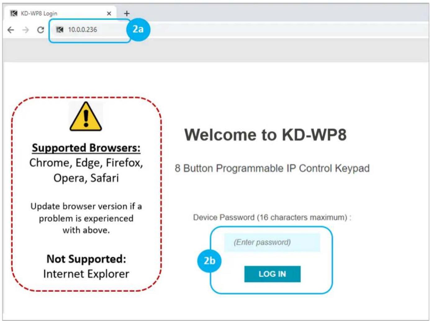
2. Connect to KD-WP8-3 via LAN with web UI.
a. Open web browser and type in the IP address of the KD-WP8-3 as set in step 1 or use default IP address 192.168.1.239 if you did not adjust the IP address.
b. Enter admin password to login to web UI. Default password is 12345678.

IMPORTANT: LAN connection between the computer and KD-WP8-3 must be constant and stable to prevent lost work. The LAN connection re-synchronizes upon entering sub-menus, applying, or saving new settings.
3. Set Device Info.
a. Device Name is displayed on the virtual keypad and is useful if multiple KD-WP8-3s are on the network.
b. LED Brightness applies to all button LED's. 1-10 value, with default setting of 10.
c. Admin Password used for accessing web UI.
d. User Password set for accessing Virtual Keypad.
e. Key Combo used to lock & unlock keypad. This is helpful for preventing unauthorized use.
f. Soft Reset may be used to wipe all programming and settings except network and password.
g. Reboot for power cycling KD-WP8-3 without physically disconnecting LAN/PoE cable.

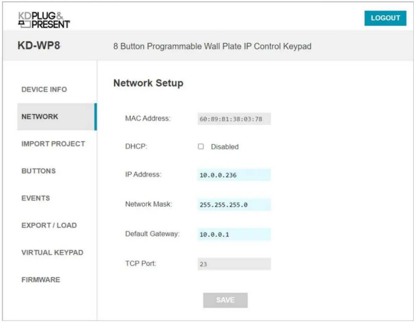
- (Optional) Network Settings. DHCP may be applied if desired.
Note: Configuration Step 1 uses KDMS Pro software for applying desired IP settings for ease of connecting via USB. Once your computer is on the same network with KD-WP8-3 it is typically easiest to do all device settings and programming using web UI.
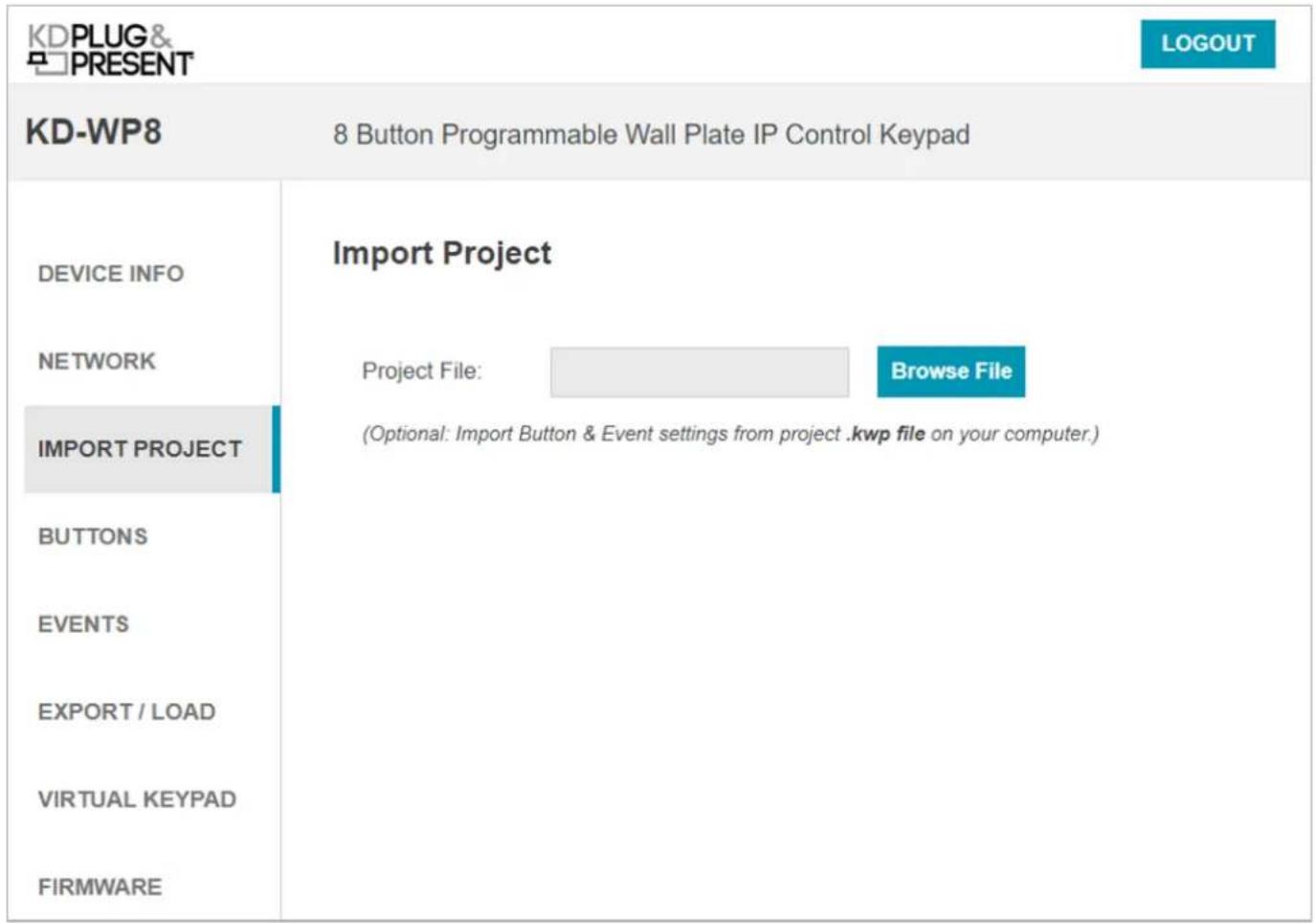
- (Optional) Import Project is used when loading a completed project file where multiple identical / similar systems are installed.
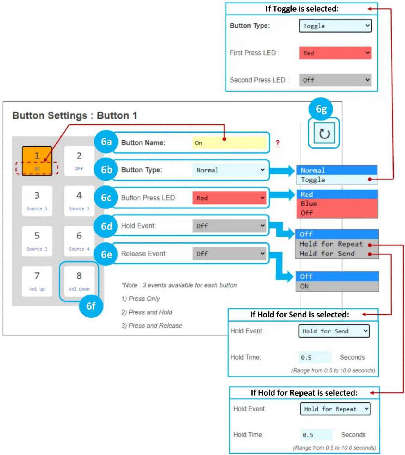
6. Apply Button & Variable Settings.
See figure 6a for Button Settings and options for each.
a. Button Name: Displayed in the virtual keypad and helps the Programmer keep button events organized.
i. Max 9 alpha-numeric characters supported (incl space).
b. Button Type: Normal or Toggle. Toggle button allows for unique event every other time the button is pressed. If Toggle, the Second Press LED is the default LED setting immediately after project load. See Example 1 in the Additional Common Button & Event Examples section.
c. Button Press LED type: Red, Blue, or None (Off). Additional LED events can be programmed in the Events section, including LED behavior of other buttons.
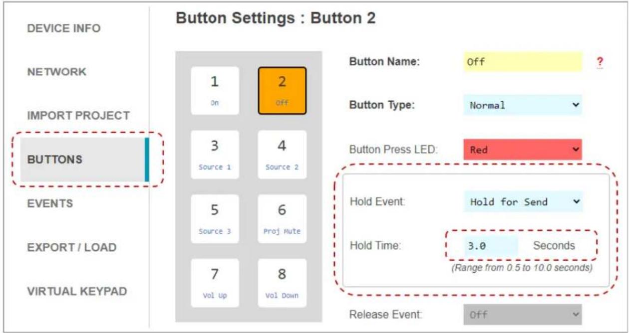
d. Hold Event type: Off, Hold for Repeat, or Hold for Send. If either Hold type is selected, enter a range between 0.5 – 10 seconds.

When Hold for Repeat is selected, there is a check box that allows you to conveniently duplicate the events of the button press, or you may uniquely program the press and hold events. See Examples 1 and 2 in the Additional Common Button & Event Examples section. Note that Hold events are not supported in Virtual Keypads from mobile and tablet browsers. KD-App does support Hold events.
e. Release Event: On or Off. Release Event On allows for unique event programming on the button Press & Release. Release event cannot be used when any Hold type is selected.
f. Choose the next button (1-8) and repeat above steps.
g. (Optional) If needed, you may refresh the settings from the active project in keypad.
CAUTION: Settings will revert to previously loaded project. Please load updates to ensure unsaved settings are not lost.
Figure 6a: Button Settings
flowchart
graph TD
    A["If Toggle is selected"] --> B["Button Type: Toggle"]
    B --> C["First Press LED: Red"]
    B --> D["Second Press LED: Off"]
    E["6g"] --> F["Button Name: On"]
    E --> G["Button Type: Normal"]
    E --> H["Button Press LED: Red"]
    E --> I["Hold Event: Off"]
    E --> J["Release Event: Off"]
    K["6a"] --> L["Button Name: On"]
    K --> M["Button Type: Normal"]
    N["6b"] --> O["Normal Toggle"]
    N --> P["Red Blue Off"]
    Q["6c"] --> R["Normal Toggle"]
    Q --> S["Red Blue Off"]
    T["6d"] --> U["Normal Toggle"]
    T --> V["Red Blue Off"]
    W["6e"] --> X["Normal Toggle"]
    W --> Y["Red Blue Off"]
    Z["6f"] --> AA["Normal Toggle"]
    Z --> AB["Red Blue Off"]
    AC["6g"] --> AD["Off Hold for Repeat Hold for Send"]
    AE["6g"] --> AF["Off Hold for Repeat"]
    AG["6g"] --> AH["Off Hold for Repeat"]
Variable Table. (Optional) You may utilize up to 8 integer variables to set values on button presses and reference those values in commands. See
h. Variable Name: Default value is VariableN (1-8). May be max 10 characters. Must be unique.
i. Default Value: Default setting is 0. Note that when keypad is power cycled the current value will revert to the default value.
j. Minimum: Default setting is 0. Potential value range is -65535 to 65535.
k. Maximum: Default setting is 65535. Potential value range is -65535 to 65535.
I. Current Value: Displays each variable's current value. Read only. Refresh page to see value updates.
BUTTONS & VARIABLES
EVENTS
EXPORT / LOAD
VIRTUAL KEYPAD
FIRMWARE
Button Press LED:

Hold Event:
Release Event:
*Note : 3 events available for each button
1) Press Only
2) Press and Hold
3) Press and Release
| No. | Variable Name ? | Default Value ? | Minimum ? | Maximum ? | Current Value |
| 1 | audio11111 | -10 | -100 | 65535 | -10 |
| 2 | pro4x1Test | 1 | 1 | 4 | 1 |
| 3 | biamp01 | -1 | -50 | 10 | -1 |
| 4 | Variable4 | 0 | 0 | 65535 | 0 |
| 5 | Variable5 | 0 | 0 | 65535 | 0 |
| 6 | Variable6 | 0 | 0 | 65535 | 0 |
| 7 | Variable7 | 0 | 0 | 65535 | 0 |
| 8 | var8888888 | 0 | 0 | 65535 | 0 |
7. Program Events (aka Commands) for each button.
IMPORTANT NOTES:
- Many device commands can be found in the IR, RS232 or IP Device Database manager software downloaded HERE. Please refer to the owner's manual or API document of the controlled device for command info if not.
- ASCII IP and RS232 command strings which include special characters like %, /, <, >, etc require entry as HEX data type. Convert each character in the string from ASCII to HEX using a CONVERSION TABLE and use 0D as a carriage return and 0A as a line feed if required. See figure 7z.
- ASCII and HEX strings may have 512 maximum characters.

a. Choose desired Button Action to program as previously set in Button Settings:
1) Button Press (Normal)
2) Button First or Second Press (Toggle)
3) Hold for Repeat or Hold for Send, if enabled
4) Release Event, if enabled
b. Enter desired name of each event. This is helpful for the programmer to keep programming organized. Max 16 alpha-numeric characters supported (incl space).
c. Choose Event Type. Example images for each event type are found in the following pages.
1) LED Addition controls LED behavior for any of the 8 buttons in addition to the pressed button's typical LED behavior. See figure 7c1.
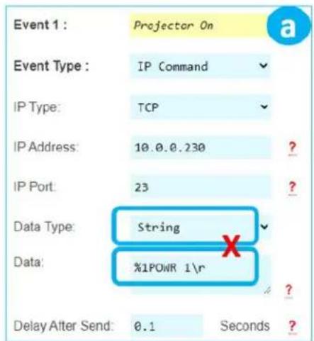
2) IP Command sends commands to control a device at the specified IP address and Port number. TCP, UDP, and Telnet formats are supported, and the data type may be String (ASCII) or HEX format. Enter command info into the Data cell, including \r for carriage return and \n for line feed if necessary. An adjustable delay can be added after the IP Command is sent. See figure 7c2a for TCP and UDP examples, and figure 7c2b for Telnet examples and notes.
3) Delay Addition adds an extra delay (0.1 -10 seconds) to control slower devices. See figure 7c3.
Variable Control see #11 below.
4) Built-In IR executes IR commands from the built-in IR port on the rear of KD-WP8-3. The IR command can be pasted from any Pronto Hex document or from Key Digital's IR Manager. An adjustable delay can be added after the command is sent. See figure 7c4.
5) Built-In RS232 executes RS232 commands from the built-in RS232 port on the rear of KD-WP8-3. Baud Rate is selectable from 1,200 to 115,200 bps. String (ASCII) or HEX data type may be selected and command info may be entered into the Data cell, including \r for carriage return and \n for line feed. An adjustable delay can be added after the command is sent. See figure 7c5.
6) IR KD-CX/922 sends IR command info to KD-CX800, KD-IP922, KD-IP1022, or KD-IP822 master controllers at the specified IP address and port number and selected I/O port. If KD-IP822 is used, please only select from I/O port 1 or 2. The IR command can be pasted from any Pronto Hex document or from Key Digital's IR Manager. See figure 7c6.
7) IR KD-MC1000 sends IR command info to KD-MC1000 master controller at the specified IP address and port number and selected I/O port. The IR command can be pasted from any Pronto Hex document or from Key Digital's IR Manager. See figure 7c7.
8) RS232 KD-CX/922 sends RS232 command info to KD-CX800, KD-IP922, KD-IP1022, or KD-IP822 master controllers at the specified IP address and port number and selected I/O port. Port 1 is not selectable as all MC models do not support RS232 on port 1. Baud Rate is selectable from 1,200 to 115,200 bps. String (ASCII) or HEX data type may be selected and command info may be entered into the Data cell, including \r for carriage return and \n for line feed. An adjustable delay can be added after the command is sent. See figure 7c8.
9) RS232 KD-MC1000 sends RS232 command info to KD-MC1000 master controller at the specified IP address and port number and selected I/O port. Baud Rate is selectable from 1,200 to 115,200
bps. String (ASCII) or HEX data type may be selected, and command info may be entered into the Data cell including \r for carriage return and \n for line feed. An adjustable delay can be added after the command is sent. See figure 7c9.
10) Relay KD-MC1000 sends info to KD-MC1000 to set the Relay port to On (Normally Open) or Off (Normally Closed). See figure 7c10.
11) Variable Control. Set a selected variable's value up, down, or to an entered integer value from -65535 to 65535. Must ensure variable's value is set as desired BEFORE referencing the variable's value in your commands (i.e. set the variable's value in Event #1, then reference the variable's value in Event #2).
d. (Optional) If needed, you may refresh the settings from the active project in keypad.
e. (Optional) You may move the current selected event up or down within the programming sequence. You may insert a new event or delete the selected event. Note that 10 events are maximum per button action.
f. (Optional) You may delete all events on the current button.
g. Choose the next button (1-8) and repeat above steps a-c.
h. You may choose to (1) copy and (2) paste the events from a programmed button to a desired destination button using the (3) Duplicate Apply button. This is a time saver when many of the events are similar on the buttons.

Figure 7c1: LED Addition Event example and options.
Button Events : Button 1
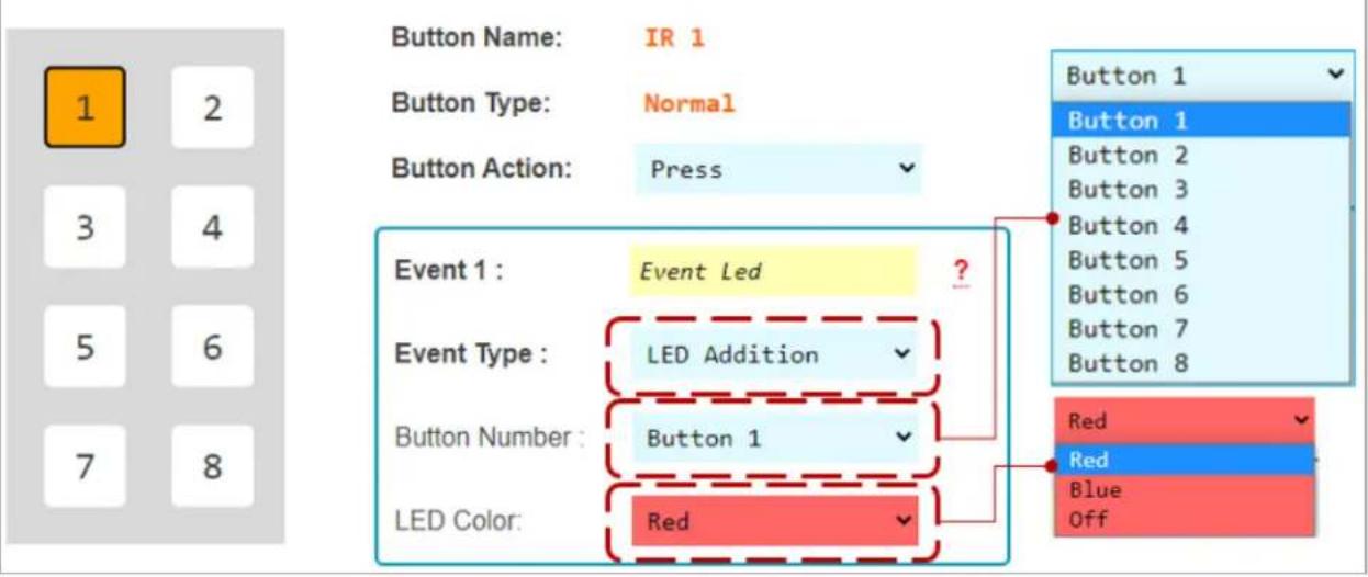
Figure 7c2a: TCP and UDP IP Command Event example and options.
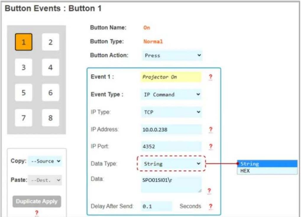
Figure 7c2b: Telnet IP Command Event example and options.
Telnet Control Notes:
a. Telnet IP control should be utilized when trying to control a device which allows you to connect, but then requires a username and password before allowing KD-WP8-3 to control the device. TCP or UDP type control should be selected otherwise.
b. Keypad supports 1 telnet connect at a time.
c. The initial connection time is dependent on the Telnet device. If user sends additional commands to the Telnet device during the connection sequence, those commands are added to the keypad's buffer and will be sent after successful connection.
d. Once connected to the telnet device, the keypad maintains connection until the telnet device closes the connection or until the keypad connects to another telnet device. Sending TCP or UDP commands to other IP devices does not interrupt the open telnet connection.
e. Login and Password cells may be left empty if you have disabled them in the controlled device.
f. Welcome Message is case sensitive. Enter one word or character combo which the Telnet device sends in its successful connection acknowledgement.
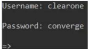
i. Example 1: Clearone welcome message includes “=>” and we use it in the below programming example.
ii. Example 2: Biamp welcome message includes "Welcome"

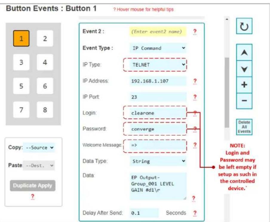
Figure 7c3: Delay Addition Event example and options.
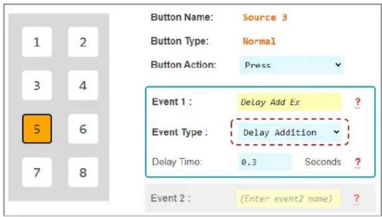
Figure 7c4: Built-In IR Event example and options. IR Data pasted from a Pronto Hex Sheet. See figure 7c4b.
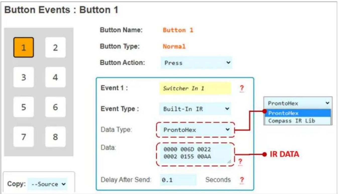
Figure 7c4b: Example Pronto Hex IR sheet collected from mfr. The highlighted hex data has been copied and pasted into the Event's Data cell.
Pronto Hex IR Sheet
Remote Model: KDRMSWPROK
Supported Models: KD-HD4X1PROK, HD2x1PROK, KD-4x1CSK, 2x1CSK, KD-S2x1, KD-S4x1, KD-Pro2x1, KD-Pro4x1, KD-S2x1X, KD-S4x1X, KD-Pro2x1X, KD-Pro4x1X
Input 1
0000 006D 0022 0002 0155 00AA 0015 0015 0015 0015 0015 0015 0040 0015 0040 0015 0015 0015 0015 0015 0015 0015 0015 0015 0015 0015 0015 0040 0015 0040 0015 0015 0015 0015 0015 0040 0015 0040 0015 0015 0015 0015 0015 0015 0040 0015 0040 0015 0015 0015 0015 0015 0040 0015 0047
Input 2
0000 006D 0022 0002 0155 00AA 0015 0015 0015 0015 0015 0015 0015 0015 0040 0015 0040 0015
Figure 7c5: Built-In RS232 Event example and options. RS232 Data is pasted from a Key Digital RS Device Database. See figure 7c5b.

Figure 7c5b: Browsing Key Digital's RS232 Database Manager for the command data used in the above example. Identifying the device, Baud Rate, and RS232 Command Data.
![RS-232 Manager (C:\Program Files (x86)\Key Digital\Compass Control\Library\RS232_Database\Key Digital_RS.lib [5.18.2016]) File New Open Save Save As Import Undo Redo Paste Cut Copy Double Delete About File Edit View Help Library Explorer Device Properties Device Class Control Properties Default Repeat Settings NC Port for Testing Device Port RS-1 Switcher Bound Rate 57600 Party None Repeat while Holding Delay 0.5 sec. MC: KD-MC2500 IP: 10, 0, 0, 238 JP Port 23 Terminal #Out: 1 Num. Bits 8 Stop 1 Repeat 1 First 0.1 sec. Alt. Repeat 1 Next 0.1 sec. DHCP MC1000-00000000000 N. Repeat: 1 #In: 4 Telnet Handshaking Interchar Delay 0 Copy Output 0 Show/Standard Terminate with: (Carriage Return) Head: ASCII HEX DEC Edit Function Add Function Delete Function Duplicate Test Function Key Digital / HDMI Switcher / KD-Pro4x1 Common/All Output 1 Show Action ID Function Name Function Data N... Repeat / Delay Description 1 POWER ON CONTROL POWER ON PNr Default / Default Power ON 2 POWER OFF CONTROL POWER OFF PFr Default / Default Power OFF 99 INPUT P1 OUTPUT A/V Input A/V #P1 SPOS/03/r 1 Default / Default >>>Set Output=Video&Audio Input P1, P1=[1-4] 10 INPUT 1 OUTPUT A/V Input A/V 03 SPOS/03/r Default / Default >>>Set Output=Video&Audio Input 01 102 INPUT 2 OUTPUT A/V Input A/V 02 SPOS/02/r Default / Default >>>Set Output=Video&Audio Input 02 103 INPUT 3 OUTPUT A/V Input A/V 03 SPOS/03/r Default / Default >>>Set Output=Video&Audio Input 03 104 INPUT 4 OUTPUT A/V Input A/V 04 SPOS/04/r Default / Default >>>Set Output=Video&Audio Input 04 CUSTOM CONTROL HELP Hr Default / Default Display Help Page CUSTOM CONTROL Reset to Factory SPCDPr Default / Default Reset to Factory Defaults Control Terminal](/content/2026/05/1065500/images/345f63977ea7ef2a1e149b63df141ef0accc01776301ce90cd9d11e1c43b81b6.jpg)
Figure 7c6: IR KD-CX/922 Event example and options. IR Data pasted from same Pronto Hex sheet as above figure 7c4b.
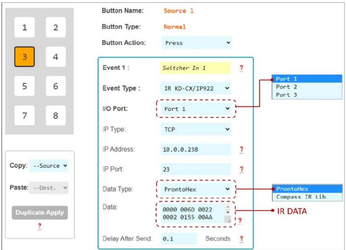
Figure 7c7: IR KD-MC1000 Event example and options. IR Data pasted from Key Digital IR Device Database. See figure 7c7b.
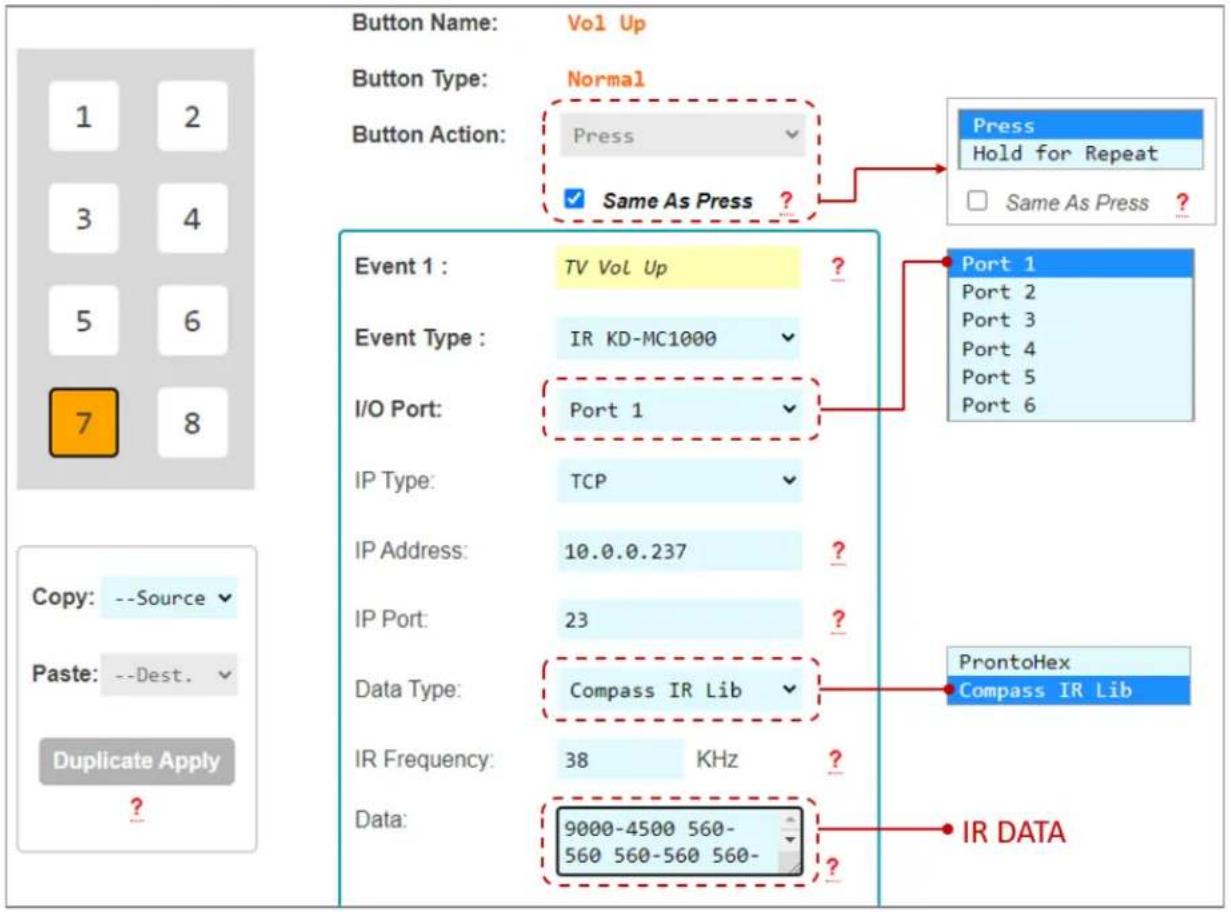
Figure 7c7b: Browsing Key Digital's IR Database Manager for the command data used in above example. Identifying the device, IR frequency, and IR Command Burst Data.
![IR Manager (C:\Program Files (x86)\Key Digital\Compass Control\Library\IR_DataBases\kd_Toshiba_IR.lib [7.28.2016]) File New Open Save Save AS Import Undo Redo Paste Cut Copy Double Delete About File Undo & Redo Clipboard About Library Explorer Device Properties Device Class Switcher Use Default Level IR output Level default V. Default Repeat Settings Repeat while Holding Delay 0.02 sec. Repeat 1 First 0.1 sec. All. Repeat 1 Next 0.1 sec. Testing and Learning Port MC (TCP-IP) Remote (RS232) MC: KD-MC2500 DHCP MC 1000-0000000000000 IP: 192, 168, 1, 63 Port: 23 Clone Output 1 Protocol Show Standard HEX DEC Prop. Remote Pronto HEX Learn / Edit Add Function Delete Function Duplicate Test Function Testing Port IR-1 Num. Repeat: Learning Port IR-1 Toshiba / Television / Most Models Common/All Show Action ID Function Name Frequency IR Burst Data Repeat / Delay Description 1 POWER ON POWER ON 38028 8966-4496 578-552 578-552 578-552 578-552 578-578-5... 2 POWER OFF POWER OFF 38028 8966-4496 578-552 578-552 578-552 578-552 578-578-5... 3 POWER TOGGLE POWER TOGGLE 38360 9040-4507 573-573 573-573 573-573 573-573 573-573 573-5... 4 VOLUME - VOLUME UP 18360 8936-4481 521-521 521-521 521-521 521-521 521-5... 5 VOLUME - VOLUME DOWN 38360 8936-4481 521-521 521-521 521-521 521-521 521-5... 6 MUTE TOGGLE MUTE TOGGLE 38360 8936-4481 521-521 521-521 521-521 521-521 521-5... Television Most Models](/content/2026/05/1065500/images/8670c419ed97385561b0d1ac91e321e564c7e4b2274c7105b091146c8c961533.jpg)
Figure 7c8: RS232 KD-CX/922 Event example and options. RS232 Data pasted from same Pronto Hex sheet as above figure 7c5b.
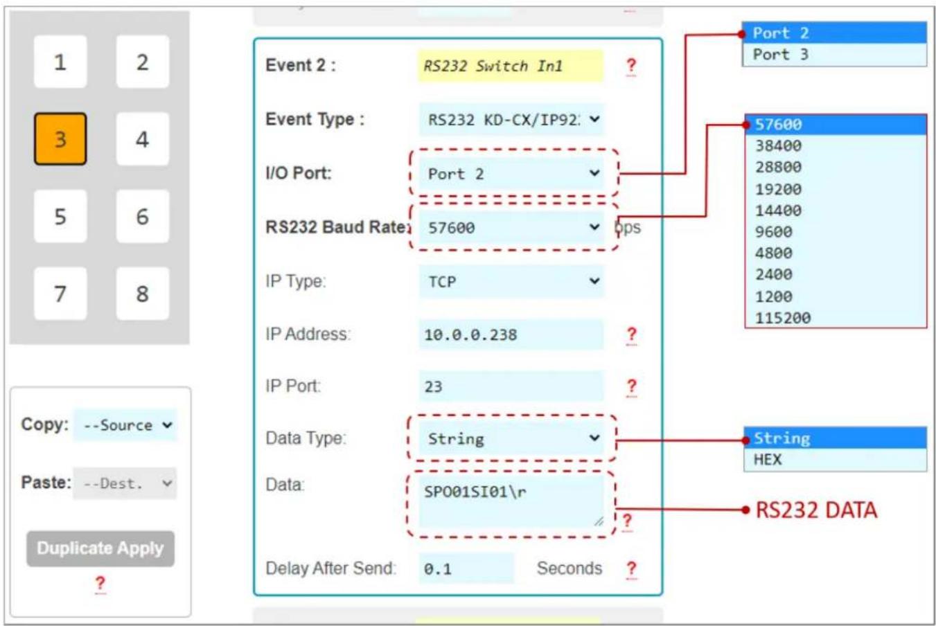
Figure 7c9: RS232 KD-MC1000 Event example and options.

Figure 7c9b: Example RS232 command info collected from Owner's Manual of the controlled device. For HEX data type, KD-WP8-3 requires each byte to be separated by a comma, without any spaces between byte.
For example:
92H, 03H, 00H, 00H, 00H
Is entered as:
92,03,00,00,00

Figure 7c10: Relay KD-MC1000 Event example and options.

Figure 7c11: Variable Control. After setting the Variable's name and default values in the Variable table, you may set the variable's value on your buttons, then reference the variable in your commands using #dN within your command data, where N = the variable number (1-8).
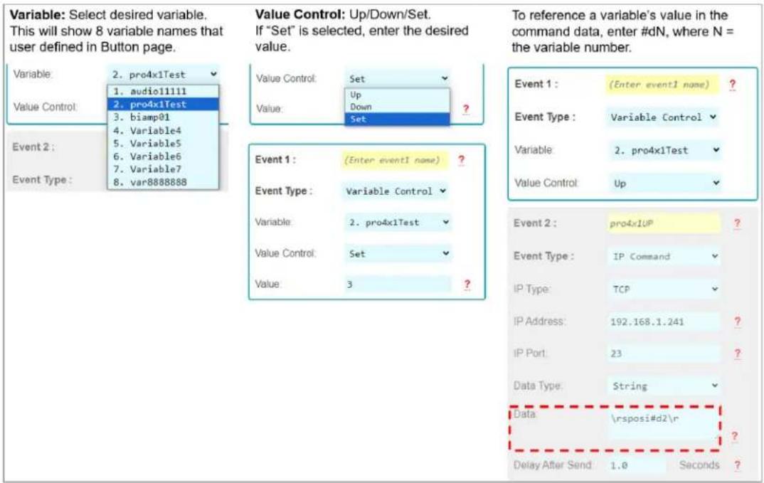
Figure 7z: ASCII IP or RS232 event which must be converted from ASCII to HEX because of special characters (i.e. %)
![Event comment = VP ON [IP Command]: IP Type = TCP IP Address - 192.168.0.220, IP Port = 4352 Data Type = String Data Size = 3 byte IP Data = 1POWR 1\r Delay After Send 0.5 second Event Command : Done (Success). Example: PJ Link projector control Command begins with character % However, in Virtual Keypad log, we can see the % character is removed causing unsuccessful control. The data must be sent as HEX type using ASCII to HEX conversion table to convert each individual character. Once exported to keypad, the control is successful.](/content/2026/05/1065500/images/50cbbe35222f6777eb34d32215c318beeaf2c3dd6239bf6536408f0b754893dc.jpg)

Common Button & Event Examples
Example 1: Toggle Button.
The Button must first be configured as a Toggle button type in the button configuration step.

Unique events may be programmed on the First and Second Button Actions.

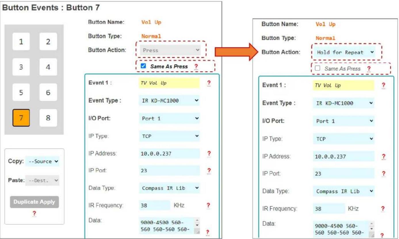
Example 2: Hold for Repeat.
The Button must first be configured for the Hold for Repeat Event and the hold time must be specified in the button configuration step.

With Same as Press applied, there is no need to program the repeated event. If unique repeated events are required, de-select Same as Press checkbox and program the Press and Hold for Repeat button actions individually. By default, Same as Press is not selected.
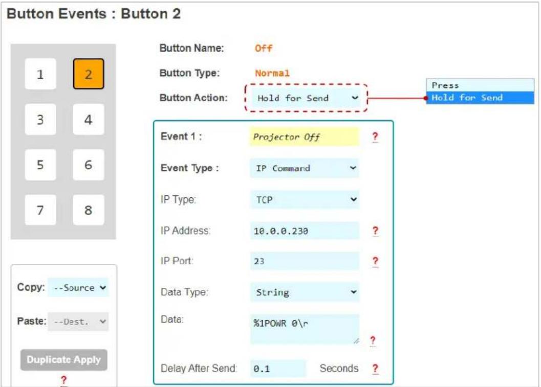
Example 3: Hold for Send.
The Button must first be configured for the Hold for Send Event and the hold time must be specified in the button configuration step. In this example, the user must hold the button for 3.0 seconds before the Hold for Send event is executed.
A Hold for Send button may also execute events on the initial button press. Or, you may leave the Press event empty if no events are desired on the initial button press.
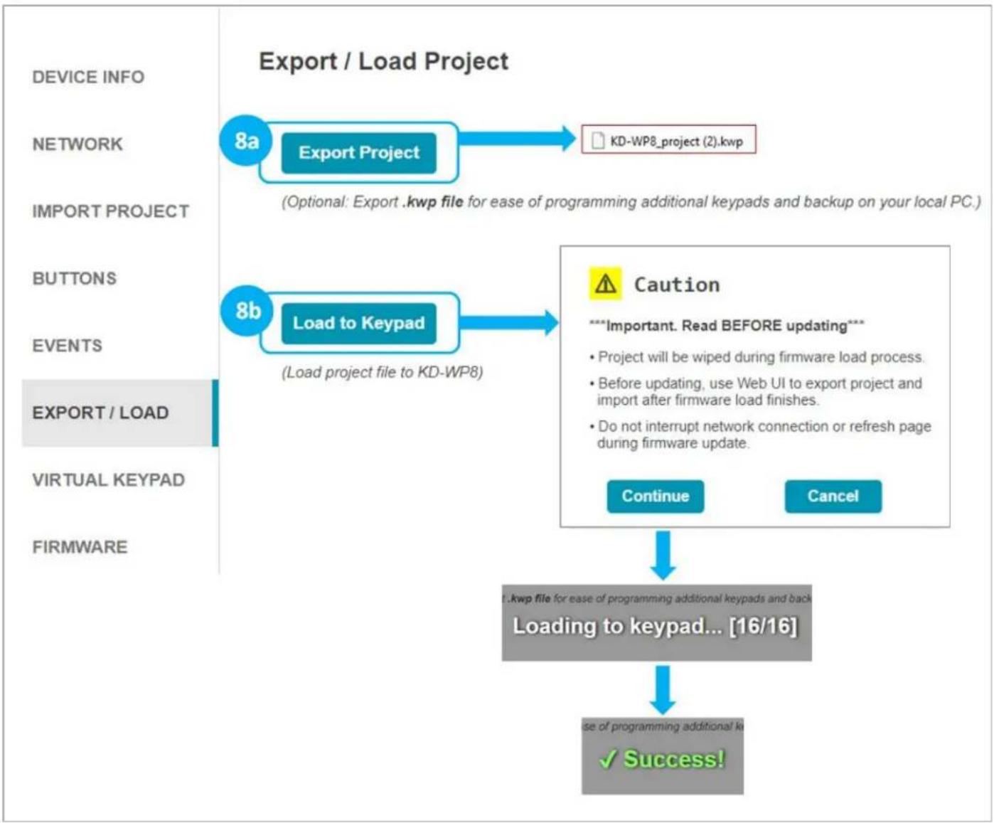
8. Export Project
IMPORTANT: Firmware updates will wipe the KD-WP8-3 of its current project load. Please export a project backup file before performing firmware updates and re-load the file after completion.
g. Press Export Project to export a .kwp project file for backup on your computer so that it may be used for loading into another KD-WP8-3.
h. Press Load to Keypad to load the programmed file into the KD-WP8-3. After successful project load and connectivity of your controlled device(s) and (optional) Key Digital Master Controllers, you may now use KD-WP8-3!
flowchart
graph TD
    A["DEVICE INFO"] --> B["NETWORK"]
    B --> C["IMPORT PROJECT"]
    C --> D["BUTTONS"]
    D --> E["EVENTS"]
    E --> F["EXPORT / LOAD"]
    F --> G["VIRTUAL KEYPAD"]
    G --> H["FIRMWARE"]

    I["Export / Load Project"] --> J["8a Export Project"]
    J --> K["KD-WP8_project (2).kwp"]
    L["8b Load to Keypad"] --> M["(Load project file to KD-WP8)"]

    N["Caution"] --> O["***Important. Read BEFORE updating***<br>• Project will be wiped during firmware load process.<br>• Before updating, use Web UI to export project and import after firmware load finishes.<br>• Do not interrupt network connection or refresh page during firmware update."]
    P["Continue"] --> Q["Cancel"]

    R["Loading to keypad... [16/16"]] --> S["✓ Success!"]
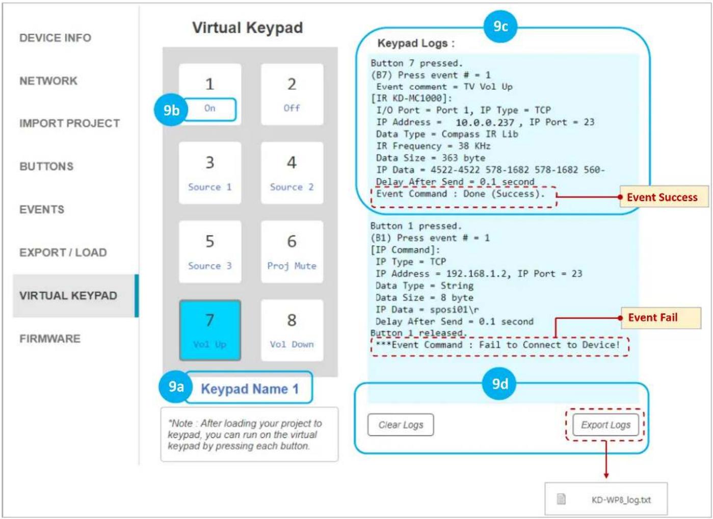
9. Virtual Keypad (Pro)
The Pro Virtual Keypad allows complete control as if you were physically pressing the KD-WP8-3 buttons. In addition to two-way buttons, the Pro Virtual Keypad also provides a log of executed events. All LED feedback in the Virtual Keypad is identical to the physical keypad.
a. Device Name is displayed as set in the Device Info setting.
b. Button Names are displayed as set in the Button settings.
c. Keypad Logs provide info for each event within the button press.
d. Keypad Logs may be Cleared or Exported as a text file.
A User Virtual Keypad may also be accessed for a simplified end-user level GUI. See the User Virtual Keypad section for more information.
flowchart
graph TD
    A["9c Keypad Logs"] --> B["9b: Button 7 pressed. (B7) Press event # = 1 Event comment = TV Vol Up [IR KD-MC1000"]: I/O Port = Port 1, IP Type = TCP IP Address = 10.0.0.237, IP Port = 23 Data Type = Compass IR Lib IR Frequency = 38 KHz Data Size = 363 byte IP Data = 4522-4522 578-1682 578-1682 560-Delay After Send = 0.1 second Event Command : Done (Success).]
    B --> C["9a Keypad Name 1"]
    C --> D["9d Clear Logs"]
    C --> E["9d Export Logs"]
    D --> F["KD-WP8_log.txt"]

Notes: For best performance, do not run Pro Virtual Keypad and User Virtual Keypad simultaneously.
Virtual Keypad is optimized for PC web browsers. For iOS users, KD-App is recommended. For Android users, Chrome browser is recommended.
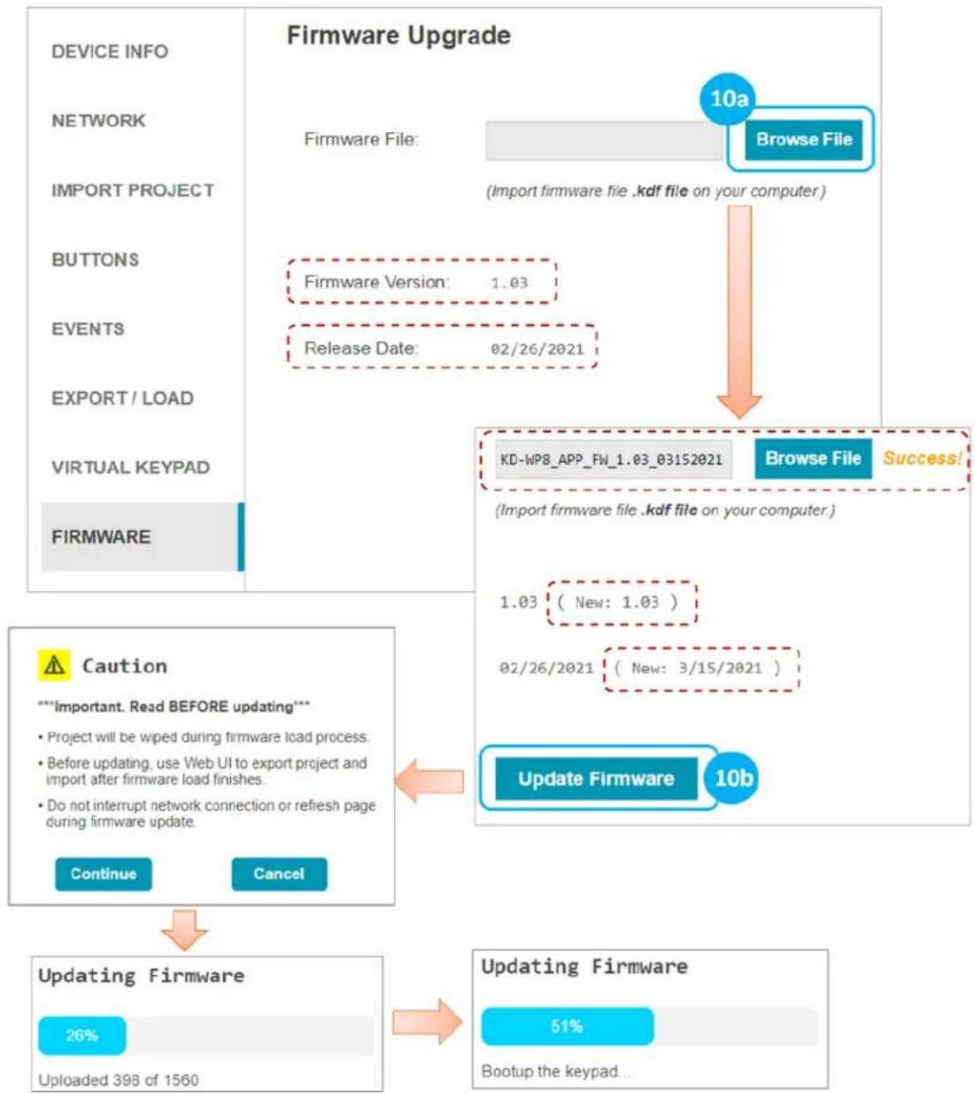
10. (Optional) Firmware
IMPORTANT: Firmware updates will wipe the KD-WP8-3 of its current project load. Please export a project backup file before performing firmware updates and re-load the file after completion. Consult with Key Digital Technical Support before updating. Hard-wired network connection is recommended.
a. Download latest firmware file from the Key Digital website, press Browse File button to choose the saved file. A success message provides information about the new firmware version number and release date.
b. Press the Update Firmware button to proceed and see the status of the firmware update and the rebooting of the unit.
flowchart
graph TD
    A["Firmware Upgrade"] --> B["10a\nFirmware File: Browse File\n(Import firmware file .kdf file on your computer)"]
    B --> C["Firmware Version: 1.03\nRelease Date: 02/26/2021"]
    C --> D["KD-WP8_APP_FW_1.03_03152021\nBrowse File Success!"]
    D --> E["1.03 (New: 1.03)\n02/26/2021 (New: 3/15/2021)"]
    E --> F["Update Firmware 10b"]
    F --> G["51%\nBootup the keypad..."]
    H["Caution"] --> I["Updating Firmware\n26%\nUploaded 398 of 1560"]
    I --> J["Continue Cancel"]
Control
IP Device Control - For IP Control, KD-WP8-3 sends commands directly to the devices via the network. No Master Controller necessary.
- Ensure that the KD-WP8-3 is on the same network as the device you are controlling via IP.
• Refer to the Programming Events section for more information. - Refer to the Owner's Manual of the device for control codes.
- Some devices may require IP control to be enabled in the setup menu and power saver / eco mode to be disabled to be controlled when in power off / standby.
- Telnet IP controlled devices have unique requirements such as Username, Password, and Welcome Message entry. Refer to the Telnet Control and Notes section.
- For TCP and UDP IP control, the keypad connects to the controlled device, sends the command, and disconnects.
- Verify control of the device using a terminal software like TeraTerm or Hercules for Hex devices.
flowchart
graph TD
    A["PoE Network"] --> B["Front"]
    A --> C[" rear"]
    D["KD-WP8"] --> A
    E["IP Devices"] --> F["Projector"]
    E --> G["Presentation Switch"]
    E --> H["Audio DSP"]
    E --> I["Lighting & Shades"]
    style A fill:#f9f,stroke:#333
    style D fill:#ccf,stroke:#333
    style E fill:#cfc,stroke:#333
IR, RS, Relay Control: KD-WP8-3 features 1 built-in IR and 1 built-in RS232 port for device control. For
additional IR, RS232, or Relay controlled devices, KD-WP8-3 sends command string and burst info to any amount KD Master Controllers.
- Ensure KD-WP8-3 is on the same network as the KD Master Controller and the devices have been configured with unique IP addresses.
- Refer to the Programming Events section for more information.
- For IR, locate the device's IR sensor, test for reliable control by repeatedly pressing button, observe the emitter blinking and successful control of the device before securing the IR emitter over the IR sensor. Use IR emitter blackout covers to prevent the emitter from falling and light from corrupting the IR signal.
| Key Digital Master Controllers | |||
| Model | Description | Ports | Power |
| KD-MC1000 | MC w/ 3.5mm IO's | 6xMulti-function, 1xRS, 1xRelay | Power Supply |
| KD-CX800 | MC w/ Phx IO's | 1xIR, 2xMulti-function | PoE |
| KD-IP1022 | AVoIP Enc/Dec w/ Phx IO's | 1xIR, 2xMulti-function | PoE |
| KD-IP922 | AVoIP Enc/Dec w/ Phx IO's | 1xIR, 2xMulti-function | PoE |
| KD-IP822 | AVoIP Enc/Dec w/ Phx IO's | 1xIR, 1xMulti-function | PoE |
- For RS232, null modem adapters or gender changers may be needed depending on the pinout of the device.
- Verify control of the device using a USB to RS232 adapter and a terminal software like TeraTerm or Hercules for Hex devices.
flowchart
graph TD
    A["front"] --> B["rear"]
    B --> C["PoE Network"]
    C --> D["IP Devices"]
    D --> E["TCP/IP UDP PJ Link"]
    C --> F["Additional RS-232, IR, Relay Devices"]
    F --> G["RD-PCX800 KD-IP1022 KD-IP922 KD-IP822 KD-MC1000 KD MCs*"]
    G --> H["RD-PCX800 KD-IP1022 KD-IP922 KD-IP822 KD-MC1000 KD MCs*"]
    H --> I["Additional RS-232, IR, Relay Devices"]
    I --> J["RD-PCX800 KD-IP1022 KD-IP922 KD-IP822 KD-MC1000 KD MCs*"]
    J --> K["Additional RS-232, IR, Relay Devices"]
    K --> L["RD-PCX800 KD-IP1022 KD-IP922 KD-IP822 KD-MC1000 KD MCs*"]
    L --> M["Additional RS-232, IR, Relay Devices"]
    M --> N["RD-PCX800 KD-IP1022 KD-IP922 KD-IP822 KD-MC1000 KD MCs*"]
    N --> O["Additional RS-232, IR, Relay Devices"]
    O --> P["RD-PCX800 KD-IP1022 KD-IP922 KD-IP822 KD-MC1000 KD MCs*"]
    P --> Q["Additional RS-232, IR, Relay Devices"]
    Q --> R["RD-PCX800 KD-IP1022 KD-IP922 KD-IP822 KD-MC1000 KD MCs*"]
    R --> S["Additional RS-232, IR, Relay Devices"]
    S --> T["RD-PCX800 KD-IP1022 KD-IP922 KD-IP822 KD-MC1000 KD MCs*"]
    T --> U["Additional RS-232, IR, Relay Devices"]
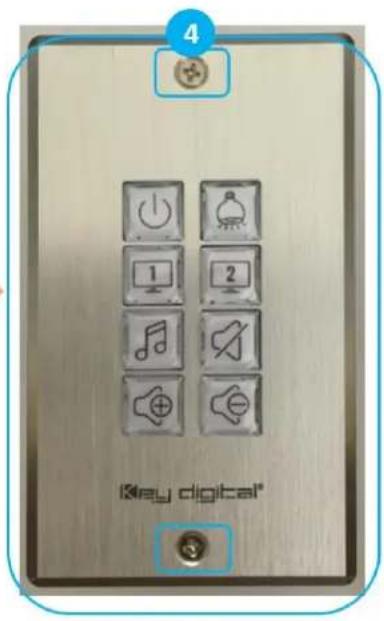
INSTALLATION IN GANG BOX
- Ensure the keypad is programmed and all 8 buttons are placed on the keypad.
- Connect network cable from PoE network switch or PoE injector into KD-WP8-3 LAN (POE) port.
- Insert KD-WP8-3 into the gang box, ensure it is right-side-up by confirming with the wording "TOP" printed on keypad. Then, fasten by using the long mounting screws.
- Place the decora plate into position and fasten using the short decora screws.
- Test the buttons by pressing a few times each, ensuring that they pop back into position and are not obstructed by the decora plate.


User Virtual Keypad
The Virtual Keypad allows complete control as if you were physically pressing the KD-WP8-3 buttons. The virtual keypad buttons display keypad & button naming, and blinks according to the LED indicator table for two-way feedback identical to the physical keypad. A similar virtual keypad is available using the Key Digital iOS app.
a. In your web browser (Internet Explorer not supported), enter the address
b. Enter the user password, as set in the Device Info menu. The default user password is user.

Note: For best performance, do not run Pro Virtual Keypad and User Virtual Keypad simultaneously. Virtual Keypad is optimized for PC web browsers. For iOS users, KD-App is recommended. For Android users, Chrome browser is recommended.
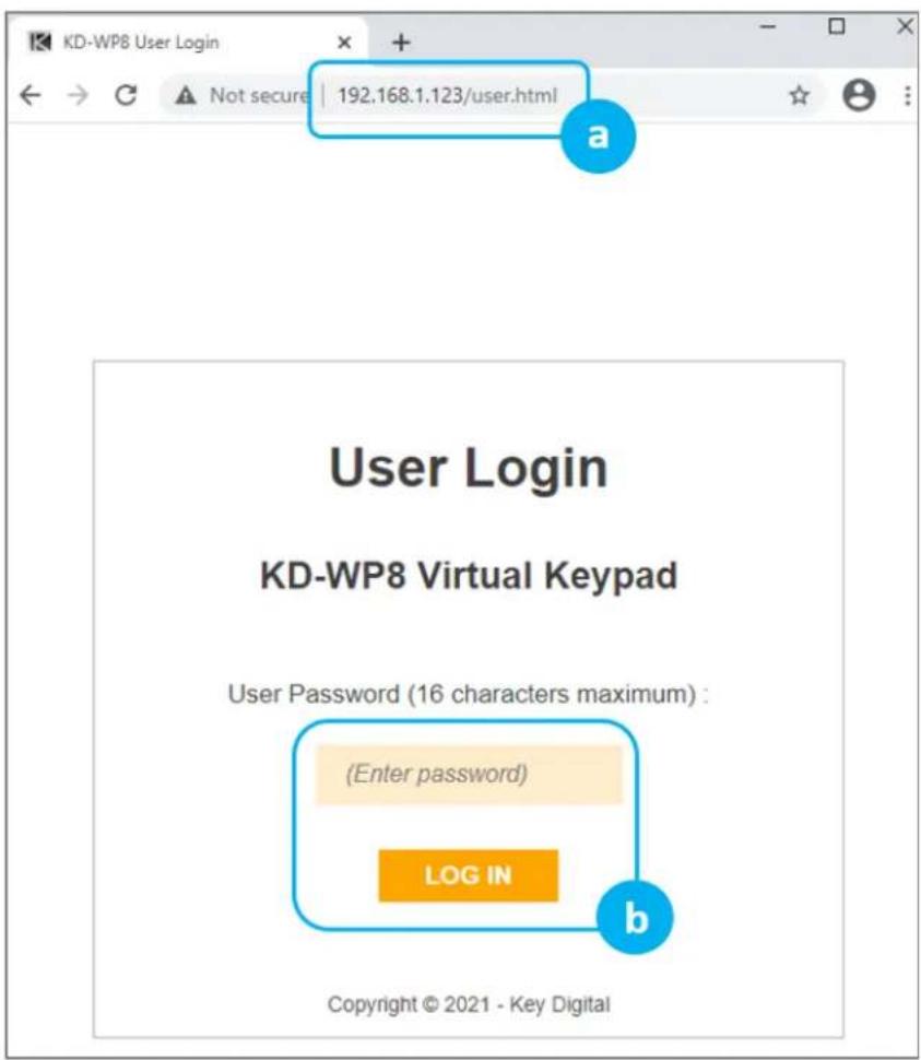
c. A simplified end-user GUI for the virtual keypad is shown after login.
(1) Device name and (2) Button names are displayed.
d. When the keypad is active (connected), the background color is light blue.
e. If disconnected, the color becomes light orange with the disconnection message.

flowchart
graph LR
    A["User Virtual Keypad"] --> B["Keypad Name 1"]
    B --> C["1 On"]
    B --> D["2 Off"]
    B --> E["c1"]
    E --> F["3 Source 1"]
    E --> G["4 Source 2"]
    E --> H["5 Source 3"]
    E --> I["6 Proj Mute"]
    E --> J["7 Vol Up"]
    E --> K["8 Vol Down"]
    L["User Virtual Keypad"] --> M["Keypad Disconnected!"]
    M --> N["1 On"]
    M --> O["2 Off"]
    M --> P["3 Source 1"]
    M --> Q["4 Source 2"]
    M --> R["5 Source 3"]
    M --> S["6 Proj Mute"]
    M --> T["7 Vol Up"]
    M --> U["8 Vol Down"]
LED Indicator Table
| Status | Description | Image |
| Bootup(Normal mode) | LEDs circleBlue5 times.After finishing bootup, all LEDs flashBluetwice quickly.Note: Bootup takes approx 10 seconds. |  |
| Bootup(Bootloader mode) | LEDs circleRed2 times.After finishing bootup, All LEDs flashRedtwice quickly.If a unit is in bootloader mode, all LEDs blink once per second, alternatingRedandBluecoloring. If in bootloader mode, the unit requires a firmware re-load via web UI or KDMS Pro. | 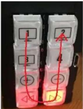 |
| Factory Reset(press & hold buttons1 + 2 + 7 + 8 for five seconds) | While holding 4 buttons, ALL LEDs flashBlueonce per second.After 5 seconds, ALL LEDs flashBlue3 times quickly and you may now release the buttons. Keypad will automatically power cycle. | 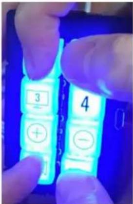 |
(Continued on next page).
| Status | Description | Image | |
| Firmware Update | While updating firmware, LEDs fill Blue & Red from the top to bottom quickly. BLUE -> RED -> BLUE....This LED display pattern repeats while firmware updates.Note: Web UI supports firmware update via IP only. KDMS Pro supports firmware update via USB and IP. | 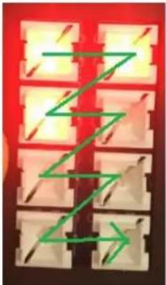 | 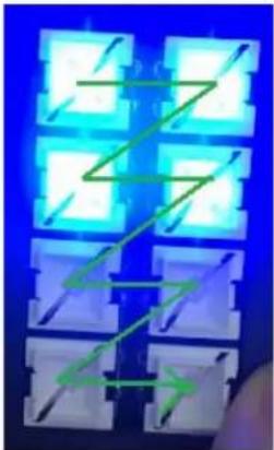 |
| Event Execute Failure | When a button is pressed on a Keypad with project loaded, that button LED will blink Red twice if KD-WP8-3 cannot reach the controlled device.The problem may be caused by an incorrect IP address or IP Port, or that the controlled device has disconnected from the network. |  | |
| Lock / Unlock Keypad | When locking via 3 second key combo hold, all LEDs flash Red twice.When unlocking via 3 second key combo hold, all LEDs flash Blue twice.If the keypad is locked, and user is tries to press button for control, all LEDs flash Red twice to indicate the keypad is locked.Note: Use the lock function to protect from unauthorized usage, for example in a classroom. |  | |
TCP/IP Control Commands
• Used for two-way integration with professional control systems.
- Default IP address is 192.168.1.239, with default port 23.
Notes:
○ Carriage Return required at end of each string.
- Commands are case-sensitive.
- After a command is received, a return message is sent from KD-WP8-3 with a carriage return (\r) at the end of the response string.
- KWPxPR\r is the most commonly used command, executing the Press & Release events from a single command.
- If Hold for Repeat or Hold for Send is selected, then KWPxP\r and KWPxR\r commands should be used.
- KWPxR\r must be received within 5 seconds following the KD-WPxP\r command otherwise the KD-WPxR\r event is automatically executed.
With firmware v1.08 and later, when a button is set to Hold for Repeat or Hold for Send, KD-WP8-3 continuously sends the button press response at the specified interval. When the button is released, KD-WP8-3 sends the release response.
○ If KWPxR\r is received without a preceding KWPxP\r, the KWPxR\r is not executed.
- For Toggle button mode, use KWPxP\r or KD-WPxPR\r. KWPxR\r will be ignored.
○ x = 1 \~ 8, button number.
○ y = R, B, F (red, blue, or off LED state of button)
| Command | Description | Response from KD-WP8-3 |
| KWPING | Ping to KD-WP8-3 | RWPING |
| KWPxP | Button x Press | RWPxP |
| KWPxR | Button x Release | RWPxR |
| KWPxPR | Button x Press + Release Combo | RWPxPR |
| KWPxLR | Button x LED Red On | RWPxLR |
| KWPxLB | Button x LED Blue On | RWPxLB |
| KWPxLF | Button x LED Off | RWPxLF |
| KWPxL | Get the LED status of each button | RWPxLy |
Responses after Button Press (physical / virtual)
| Button Type | User Action | Response from KD-WP8-3 |
| Normal | Button x Pressed | RWPxP |
| Normal | Button x Released | RWPxR |
| Toggle | Button x First Press | RWPxFP |
| Toggle | Button x Second Press | RWPxSP |
IR AND RS232 PORT INFORMATION
Use the IR and RS232 ports to control devices according to the following pinout. For ease of installation, a pre-stripped RS232 cable with pinout documented by the manufacturer is recommended. Example
| Keypad Pin # | Signal | Cable on KD Accessory | ||
 | 1 | IR Out | Striped wire on KD IR Emitter | |
| 2 | Ground (shared by IR and RS-232) | Solid wire on KD IR Emitter | ||
| 3 | RS-232 TxD | (not included) | ||
| 4 | RS-232 RxD | (not included) | ||
• Maximum IR and RS232 cable length = 500ft (verified with 115,200 baud rate)
• Supported IR burst frequency = 10kHz - 90kHz
• RS232 baud rates = 1,200 - 115,200
- Driving Voltage = 5V / 24mA
- Commands executed through the ports via two operation modes. Mode is selected using KDMS Pro
○ Mode 1: Standard & Compass Control Pro (default). This is the most commonly used mode.
○ Mode 2: Open API (optional)
- RS232 port properties are established using KDMS Pro if set to Open API mode.
- IMPORTANT: KD-WP8-3's IR and RS232 ports cannot simultaneously run in both Standard / Compass mode and Open API mode. In Open API mode, built-in IR & RS232 commands programmed in web UI
and Compass will NOT run. However, IP commands programmed into KD-WP8-3 may run regardless of the selected control mode.
KD-WP8-3 IN COMPASS CONTROL PRO SYSTEMS
Download Compass Control Navigator software suite 2.0.7 or later to use KD-WP8-3 as a master controller. Compass Control Pro requires C1 certification to download and program. The Compass Control iPad must use app version 2.0.17 or later.
- Add KD-WP8-3 as a master controller ONLY IF you will control an IR and/or RS232 device from the built-in IR RS232 ports.
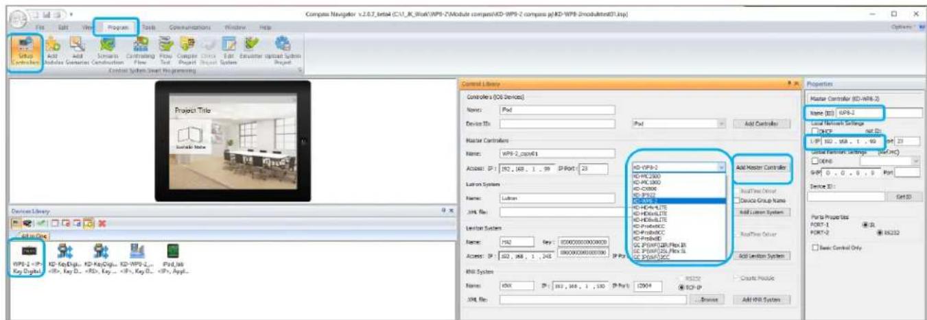
a. Go to PROGRAM → SETUP CONTROLLERS. Choose KD-WP8-2 from Master Controllers list and press ADD MASTER CONTROLLER button. The device is now visible in the All-In-One Devices Library.
b. Enter the desired IP address of the KD-WP8-2 in the PROPERTIES window at right-side of screen. Enter a unique name for the KD-WP8-2 if you have multiple units in the project.
- Add KD-WP8-2 module ONLY IF you wish to have the KD-WP8-3 Virtual User Keypad in the Compass Control UI.
a. Download module from the Compass Modules Page, save in desired location, and extract zip folder.
b. Go to PROGRAM → ADD MODULES. In the MODULE TYPE section at top-center of screen, select USER MODULE, press the “...” ellipsis button and navigate to the saved .MOD file module location and select the module. In Compass Navigator, the KD-WP8-3 module is now visible, choose it and press the ADD DEVICE button. KD-WP8-3 will now be visible in the ALL IN ONE devices library section.
c. Enter the desired IP address of the KD-WP8-3 in the PROPERTIES window at right-side of screen. Enter a unique name for the KD-WP8-3 if you have multiple units in the project.
![Compass Navigator v2.0.4 (C:\Users\acer\Desktop\compass projects(KDWPB2_Example.ksp) File Edit View Program Tools Communications Window Help Setup Add Modules Controling Flow Edit Imulator Upload System Project Controls Devus Flow Test System Project Control system Smart Programming Conference Room Device Library All in One KD-WPB-1, Focus_IN, KD-KeyO1, WPB-2, iPad_Lab , Key... , Inf... , Key... , Ke... , AppL. Control Library Module Type User Module KD-WPB-2_module_v1.mxd MC Ports for Testing RC: RS-232 Server Module TCP/IP KD Server Module Refresh P: 192_168_0_223 Type Filter Add Module to Project MAC: 00:00:00:00:00:00 IP Show All Types Default Add Device Part: 2 Rep Brand Modul All Brands Key Digital Function List: Button press Button press+release Button release Button x Led Blue Button x Led Off Button x Led Red Get Button LED color Flag Control Device Name (ID) KD-WPB-2_module_v1 Device Definition Category: Control Brand: Key Digital Type: ControlsYS Model: KD-WPB-2 Set On Device Control [Reference MC] DNCP DOHS L-BP 192_168_1_99 Part 23 G-R 0_0_0_0 Part Real-Time buffer in NC 54](/content/2026/05/1065500/images/ef0bb763f5915c9fe1f1b093b8bf3067626c27027d23820e5c8f471b288ae9ba.jpg)
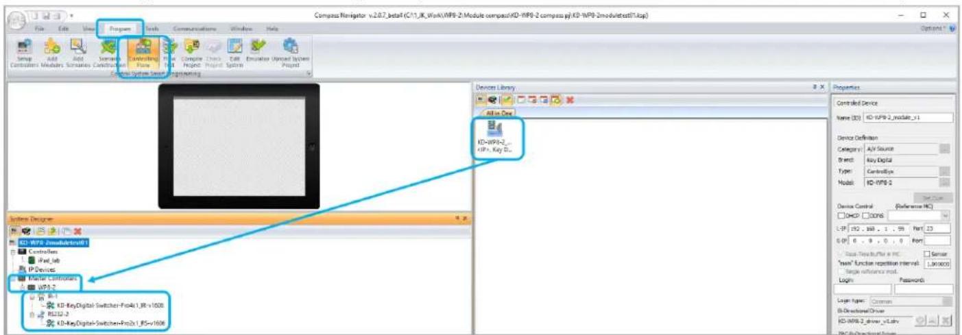
- For Master Controller and/or Module, add the device(s) to the CONTROLLING FLOW tree.
a. Go to PROGRAM → CONTROLLING FLOW. Drag the devices one-by-one into the SYSTEM DESIGNER window into their correct designated area of the tree. The Master Controller drags to the MASTER CONTROLLERS section, the module goes to the IP DEVICES section.
b. If using as a Master Controller, you may connect the IR and/or RS232 device to the two control ports.
- Refer to Module Manual for additional programming instructions if using the KD-WP8-3 module.
- You may also use KD-WP8-2 in the IR and RS232 database managers to verify and create commands.
a. Ensure that IR-1 device port is selected if testing IR commands. Ensure that RS232 device port is selected if testing RS232 commands.
![IR Manager (CA\Program Files (x86)\Key Digital\Compass Control\Library\IR_DataBases\kd_Key Digital_IR.lib [5.18.2016]) File New Open Save Save As Import Undo Redo Paste Cut Copy Double Delete About File Item Undo & Redo Clipboard About Library Explorer kd_New_IR Key Digital HDMI Switcher AV Switcher Video Processor Auxiliary Device Properties Device Class Control Properties Default Repeat Settings Testing and Learning Port: Switcher Use Default Level Delay 0 sec. #Out: 0 IR output Level Repeat 1 First 0.1 sec. #In: 15 default V. Alw. Repeat: 1 Next: 0.1 sec. Clone Output 1 Protocol Show Standard HEX DEC Prog. Remote Pronto HEX Open API Learn / Edit Add Function Testing Port MC: ID-WPS-2 MD-MC2500 MD-MC1000 KD-CX800 KD-IP922 KD-WPS-2 KD-HD4x4LITE KD-HD6x6LITE KD-HD8x8LITE Testing Port IR-1 Test Function Show Action ID Function Name Frequency IR Burst Data Reset / Delay Description](/content/2026/05/1065500/images/4ecabc100f9a1ece9daaba68ad8e675ae9097c1a564b220de3f141a6a7a7c58e.jpg)
- For more information, Compass Control Programming training is available online.
Open API Control of IR & RS232 Ports
After using KDMS Pro to select KeyCode Open API control mode KD-WP8-3 will listen on a dedicated TCP port for that I/O port.
The control system / user application can then make a TCP connection to that port and send data to that I/O port.
IP Port number assignments for I/O ports are flexible, and are assigned using KDMS Pro. It is recommended that TCP Port assignments always be no lower than 1024.
All I/O port traffic is limited to only one TCP connection at a time.
Refer to the KeyCode Open API Document for full details.
Controlling RS-232 Devices
Send any RS-232 string to the KD-WP8-3 over IP on port 4582 (or the updated IP port # if changed in KDMS Pro).
Specify ASCII, HEX, or Binary string format in the control system / user application as the KD-WP8-3 is transparent and does not apply any formatting. Include carriage return or line feed characters if required by the device you are controlling.

Controlling IR Devices
Send IR commands to KD-WP8-3 over IP on port 4581 (or the updated IP port # if changed in KDMS Pro).
Collect the IR command Hex info using Key Digital IR Database Manager v2.0.6 or later. Navigate to the desired make & model's IR code set and choose the desired command then press the Open API button to view the IR Data in its specialized format necessary for utilizing the Open API. Copy the IR Data to your clipboard and paste it into your Control System / User Application. Add a carriage return at the end of the string sent from the Control System / User Application for the KD-WP8-3 unit to execute the command.
Specifications
Technical
- RJ45 Connectors: Shielded Link Connector, 1x LAN
- Unit Control: Bi-directional TCP/IP on RJ45, USB Micro
- IR and RS-232: 4pin phoenix connector with shared ground.
General
• Regulation: CE, RoHS, WEEE, EAC
- Buttons: 8 blue/red backlight buttons with clear outer cap
• Wall plate: U.S. 1-gang wall plate in aluminum enclosure
• Decora plate: Brushed aluminum
• Product Dimensions: 4.13" x 1.93 x 1.21" (105 x 49 x 30.8 mm)
• Product Weight: Weight: 0.5 lbs / 0.23kg
- Packaging Dimensions: 5.75" x 4.13" x 2.56" (146 x 105 x 65 mm)
• Packaging Weight: 1.5 lbs / 0.68kg
Warranty Information
All Key Digital® products are built to high manufacturing standards and should provide years of trouble-free operation. They are backed by a Key Digital Limited 3 Year Product Warranty Policy.
http://www.keydigital.com/warranty.htm
Product Warnings & Safety Instructions

Important Product Warnings:
- Connect all cables before providing power to the unit.
- Test for proper operation before securing unit behind walls or in hard to access spaces.
- If installing the unit into wall or mounting bracket into sheet-rock, provide proper screw support with bolts or sheet-rock anchors.

Safety Instructions:
Please be sure to follow these instructions for safe operation of your unit.
- Read and follow all instructions.
- Heed all warnings.
- Do not use this device near water.
- Clean only with dry cloth.
- Install in accordance with the manufacturer's instructions.
- Do not install near any heat sources such as radiators, heat registers, stoves, or other apparatus (including amplifiers) that produce heat.
- Only use attachments/accessories specified by the manufacturer.
- Refer all servicing to qualified service personnel. Servicing is required when the device has been damaged in any way including:
o Damage to the power supply or power plug
- Exposure to rain or moisture

Power Supply Use:
You MUST use the Power Supply provided with your unit or you VOID the Key Digital® Warranty and risk damage to your unit and associated equipment.

natural_image
Completely dark image with no visible content or text.
natural_image
Black-and-white portrait of a man with glasses and mustache, looking upward (no text or symbols visible)Key Digital ^® , led by digital video pioneer Mike Tsinberg, develops and manufactures high quality, cutting-edge technology solutions for virtually all applications where high-end video and control are important. Key Digital ^® is at the forefront of the video industry for Home Theater Retailers, Custom Installers, System Integrators, Broadcasters, Manufacturers, and Consumers.
Key digital®
The Experts in Digital Video Technology and Solutions™


- Setup & Programming Guide KD-WP8-3
- Table of Contents
- Default IP Address: 192.168.1.239
- Accessories
- About KD-WP8-3
- Key Features
- Application Diagrams
- Quick Setup Guide
- Button Caps
- Connect
- Configure
- Set the desired IP Address and Control Mode via KDMS Pro
- Connect to KD-WP8-3 via LAN with web UI.
- Set Device Info.
- Apply Button & Variable Settings.
- BUTTONS & VARIABLES
- Program Events (aka Commands) for each button.
- IMPORTANT NOTES:
- Telnet Control Notes:
- Pronto Hex IR Sheet
- Input 1
- Input 2
- Common Button & Event Examples
- Example 1: Toggle Button.
- Example 2: Hold for Repeat.
- Example 3: Hold for Send.
- Export Project
- Virtual Keypad (Pro)
- (Optional) Firmware
- Control
- INSTALLATION IN GANG BOX
- User Virtual Keypad
- TCP/IP Control Commands
- Notes:
- IR AND RS232 PORT INFORMATION
- KD-WP8-3 IN COMPASS CONTROL PRO SYSTEMS
- Open API Control of IR & RS232 Ports
- Controlling RS-232 Devices
- Controlling IR Devices
- Specifications
- Technical
- General
- Warranty Information
- Product Warnings & Safety Instructions
- Important Product Warnings:
- Safety Instructions:
- Power Supply Use:
Brand : Key Digital
Model : KD-WP8-3
Category : Router