ETHM-A - Detector Satel - Free user manual and instructions
Find the device manual for free ETHM-A Satel in PDF.

| Product Type | Wired Motion Detector |
| Brand | Satel |
| Model | ETHM-A |
| Dimensions (H x W x D) | 100 x 60 x 40 mm |
| Weight | 120 g |
| Power Supply | 12 V DC |
| Current Consumption | 15 mA (standby), 25 mA (alarm) |
| Detection Method | Passive Infrared (PIR) |
| Detection Range | Up to 12 m, 90° angle |
| Tamper Protection | Yes, tamper switch |
| Alarm Output | NC/NO relay, 24 V DC / 0.5 A |
| Operating Temperature | -10°C to +40°C |
| Mounting | Wall or ceiling, included bracket |
| Maintenance | Clean lens with soft dry cloth; check connections periodically |
| Safety | Low voltage, CE compliant |
| Spare Parts / Repairability | Not user-serviceable; contact Satel service |
| General Information | Designed for indoor use with Satel alarm panels |
Frequently Asked Questions - ETHM-A Satel
User questions about ETHM-A Satel
0 question about this device. Answer the ones you know or ask your own.
Ask a new question about this device
Download the instructions for your Detector in PDF format for free! Find your manual ETHM-A - Satel and take your electronic device back in hand. On this page are published all the documents necessary for the use of your device. ETHM-A by Satel.
USER MANUAL ETHM-A Satel
natural_image
Illustration of a Satel device with labeled ports (APS, OA, OB) and green connectors (no text beyond branding)Firmware version 1.00 ethm-a_en 11/21
EN
The module should be installed by qualified personnel.
Prior to installation, please read carefully this manual in order to avoid mistakes that can lead to malfunction or even damage to the equipment.
Disconnect power before making any electrical connections.
Changes, modifications or repairs not authorized by the manufacturer shall void your rights under the warranty.
The rating plate of the device is located on the enclosure base.
FreeRTOS is used in this device (www.freertos.org).
SATEL aims to continually improve the quality of its products, which may result in changes in their technical specifications and software. The current information on the introduced modifications is available on our website.
Please visit us: https://support.satel.eu
The declaration of conformity may be consulted at www.satel.eu/ce
The following symbols may be used in this manual:

- note;

- caution.
CONTENTS
- Introduction......3
- Features .... 3
- Typical module applications ....5
3.1 Supervision / control of devices 5
3.2 Simulation of monitoring station....5
3.3 Work within the Internet of Things (IoT)....6
-
Description of the module....6
-
Installation 8
5.1 Preparing the cabling....8
5.2 Installation of the module 8
5.3 Connecting the alarm control panel 8
5.4 Connecting the devices to the inputs and outputs 8
5.5 Connecting the digital temperature sensors (1-Wire) 9
5.6 Connecting the power supply and starting the module....9
- Configuring....10
6.1 Description of the GX Soft program 10
6.1.1 Startup window....10
6.1.2 Menu bar in the GX Soft program....12
6.1.3 Side menu....13
6.1.4 Status panel....13
6.1.5 Additional menu 13
6.1.6 "Settings" window....16
6.2 Establishing communication with the module 17
6.2.1 Local connection....17
6.2.2 Remote connection: SATEL server....17
6.2.3 Remote connection: direct connection in the local network....18
6.2.4 Remote connection: direct connection in the public network....18
6.3 Project....18
6.4 Hardware 19
6.4.1 Mainboard 19
6.4.2 Network....21
6.5 Inputs 21
6.5.1 Status....21
6.5.2 Settings....22
6.5.3 Bypasses....23
6.5.4 Analog input settings....23
6.6 1-Wire sensors....25
6.6.1 Status....25
6.6.2 Settings 25
6.7 Outputs 26
6.7.1 Control....26
6.7.2 Settings 26
6.7.3 Triggering....27
6.8 Communication....28
6.8.1 SATEL server....29
6.8.2 Direct connection to GX Soft....29
6.9 Station simulation....29
6.10 Reporting 31
6.10.1 Module events distribution ....34
6.10.2 Event codes ....34
6.11 Messaging....34
6.12 Event converter 35
2 ETHM-A SATEL
6.13 Remote update....36
6.14 IoT 37
6.15 Users 40
6.16 Events....40
-
GX Control application....41
-
Module firmware update ....43
8.1 Local update 43
8.2 Remote update 44
-
Restoring the factory settings 44
-
Specifications 44
-
Appendix....44
11.1 Data format for MQTT, JSON and JSON/HTTP protocol 44
11.1.1 Format of frames sent by the module 44
11.1.2 Format of the module control frame 46
11.1.3 Format of the event log reading frame 47
1. Introduction
This manual describes the ETHM-A module and how it should be installed as well as configured using the GX Soft program.
2. Features
Communication
- Encrypted communication via Ethernet.
• Control of the Ethernet cable presence.
Reporting
- Reporting events to two monitoring stations.
-
Possibility to report to two monitoring station servers.
• Several communication formats: -
SIA,
- Contact ID (CID),
- Ademco Express,
– Sil. Knight / Ademco slow, - Radionics 1400Hz,
- Radionics 1400 with parity.
- Converting and retransmitting codes of events received from the control panel (simulation of telephone monitoring station).
Messaging
- Notification of events related to the module and received from other devices.
• E-mail notification to up to 8 addresses. - Possibility to send push notifications to GX Control application users.
Event log
- Capability of storing up to 500 events generated by the module or received from the control panel.
Inputs
- 8 inputs, programmable as:
- digital, NO type,
-
digital, NC type,
– analog (voltage measurement 0...16.56 V). -
Input for supervision of AC voltage presence or for AV voltage frequency measurement.
- Supervising the status of external devices.
- Capability of input bypassing.
Outputs
- 4 programmable OC type outputs.
- Controlling external devices or signaling troubles.
1-Wire bus
- Support for up to 8 digital 1-Wire temperature sensors.
Control
- Controlling outputs or bypassing the module inputs by means of:
- inputs,
- GX Soft program,
– GX Control application,
- Possibility of bypassing the 1-Wire sensors from GX Soft program and GX Control application.
Work within the Internet of Things (IoT)
- Possibility of integrating the module with automation systems, measuring data acquisition systems, etc.
Operation from mobile devices
- Free GX Control application for remote operation of the module.
- Functions available from the application:
– checking the status of inputs and outputs,
- bypassing / unbypassing inputs,
- bypassing / unbypassing 1-Wire sensors,
- controlling outputs,
– viewing troubles,
– viewing the event log.
- Simple and easy establishing remote communication between GX Control application and the module thanks to SATEL's connection setup service.
Configuring
- Free GX Soft program for local (USB port) and remote (Ethernet) configuring of the module.
- Simple and easy establishing remote communication between GX Soft program and the module thanks to SATEL's connection setup service.
Firmware update
- Local firmware update by using a computer connected to USB port.
- Remote update of the module firmware by using the "UpServ" server via Ethernet.
LEDs
• LEDs indicating the module status.
Power supply
• Powering with 12 VDC (±15%).
- Connector for SATEL's dedicated power supply unit.
3. Typical module applications
The extended functionality of ETHM-A module enables it to be used for a variety of applications. This section presents typical examples of its application. Some of them may be combined with one other.
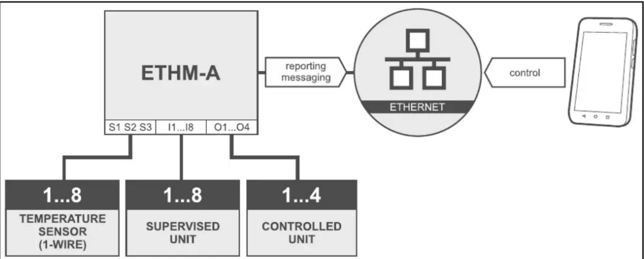
3.1 Supervision / control of devices
flowchart
graph TD
    A["ETHM-A"] --> B["Reporting Messaging"]
    B --> C["ETHERNET"]
    C --> D["Control"]
    A --> E["S1 S2 S3 I1...I8 O1...O4"]
    E --> F["1...8 TEMPERATURE SENSOR (1-WIRE)"]
    E --> G["1...8 SUPERVISED UNIT"]
    E --> H["1...4 CONTROLLED UNIT"]
Fig. 1. Module supervising operation of the devices connected to inputs and controlling operation of the devices connected to outputs.
Changing the input status / exceeding the defined threshold limit value may result in:
- sending event code to the monitoring station (Ethernet reporting);
- event notification (messaging) by means of e-mail / push.
The inputs can be bypassed locally (by means of one of the module inputs or in the GX Soft program) or remotely (in the GX Soft program or the GX Control application).
1-Wire sensors can be bypassed from GX Soft program or GX Control app.
The devices connected to the module outputs can be controlled locally (by means of module inputs or in the GX Soft program) or remotely (in the GX Soft program or the GX Control application).
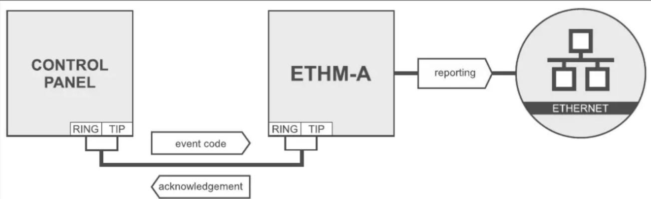
3.2 Simulation of monitoring station
flowchart
graph LR
    A["CONTROL PANEL"] -->|RING TIP| B["ETHM-A"]
    B -->|RING TIP| C["ETHERNET"]
    C --> D["REPORTER"]
    D --> E["REPORTER"]
    F["event code"] --> B
    G["acknowledgement"] --> B
Fig. 2. Module simulating the monitoring station.
The module can forward the event codes received from the control panel to the monitoring station by means of Ethernet.
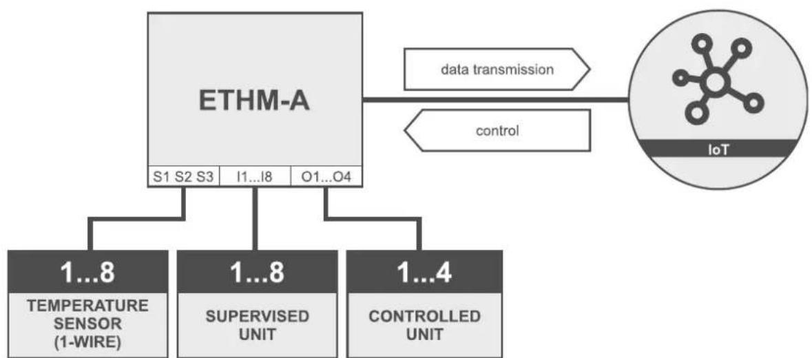
3.3 Work within the Internet of Things (IoT)
flowchart
graph TD
    A["ETHM-A"] --> B["S1 S2 S3"]
    A --> C["I1...I8"]
    A --> D["O1...O4"]
    A --> E["1...8 TEMPERATURE SENSOR (1-WIRE)"]
    A --> F["1...8 SUPERVISED UNIT"]
    A --> G["1...4 CONTROLLED UNIT"]
    H["data transmission"] --> A
    I["control"] --> A
    J["IoT"] --> K["Network Icon"]
Fig. 3. Module working within Internet of Things (IoT).
Using Ethernet (TCP), the module can communicate with devices in the Internet of Things (IoT). This allows the module to be integrated e.g. with automation systems and measurement data acquisition systems. The module can send information about the status of inputs / outputs as well as data from analog inputs and 1-Wire bus to the IoT devices. In response, the module can receive commands to bypass / unbypass the inputs as well as to activate / deactivate the outputs of the module.
4. Description of the module
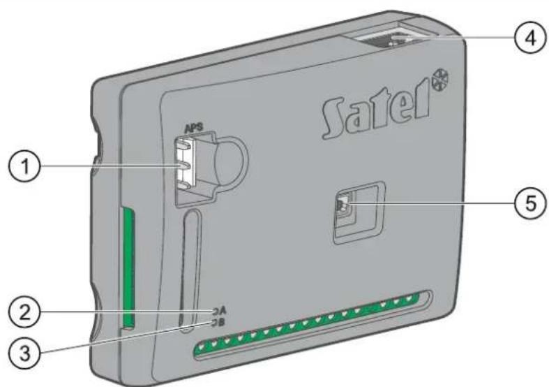
Fig. 4. ETHM-A module.
① APS connector for a SATEL power supply unit (e.g. APS-412).
② LED A:
ON – power OK, flashing rapidly – communication with GX Soft program or GX Control app in progress.
③ LED B:
flashing slowly – power OK, flashing rapidly – data transmission.
④ RJ-45 connector for Ethernet network. It is provided with two LEDs:
green – ON when the module is connected to the network, yellow – flashes during data transmission.
⑤ USB MINI-B port.
Description of terminals
+12V - power input (12 VDC ±15%).
COM - common ground.
RING, TIP – terminals for connecting the control panel telephone communicator.
S1...S3 – 1-Wire bus (digital 1-Wire temperature sensors can be connected to the bus):
S1 – common ground, S2 – data, S3 – power supply.
I1...I8 – inputs. They can be programmed as digital (NC or NO type) or analog ones.
01...04 – programmable OC type outputs (disconnected from common ground / shorted to common ground).
A RS B – terminals for future use (RS-485).
AC – input for supervision of AC voltage presence or for AC voltage frequency measurement.

natural_image
Technical drawing of a vehicle rear bumper with 26 mm dimension label (no other text or symbols)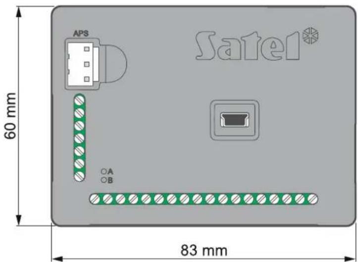
Fig. 5. Dimensions of ETHM-A module enclosure.
5. Installation

The device is designed to be used only in the local area networks (LAN). It must not be connected directly to the public computer network (MAN, WAN). For establishing connection with public networks, use a router or xDSL modem.
Disconnect power before making any electrical connections.
The ÊTHM-A module should be installed indoors, in spaces with normal air humidity.

If the module is to comply with requirements of the EN 50131 standard for Grade 2, it must be installed in an additional enclosure that will enable it to meet requirements of the tamper standards (e.g. in the SATEL OPU-3 or OPU-4 enclosure).
5.1 Preparing the cabling
To make electric connections between the module and other devices, use an unshielded non-twisted cable. Do not lay the cables in immediate vicinity of the low-voltage electrical network wires, especially those used for supplying the high-power equipment (such as electric motors).
Connect the module to the Ethernet using a 100Base-TX standard compliant cable (identical to that used for connecting computers to the network).
5.2 Installation of the module
The module enclosure base makes it possible to secure the module to the mounting surface by using e.g. a cable tie or angle hooks.
5.3 Connecting the alarm control panel
Connect the control panel telephone communicator to the TIP and RING terminals.
5.4 Connecting the devices to the inputs and outputs
- Connect the devices whose operation is to be monitored by the module to the input terminals.
- Connect the devices which are to be controlled by the module to the output terminals.
- If the module is to be powered from the SATEL APS-15 or APS-30 power supply unit, you can connect to the AC input terminal the wire from the secondary winding of the transformer which supplies the AC voltage to the power supply unit (fig. 6). This will enable the ETHM-A module to supervise the presence of AC voltage or measure its frequency.
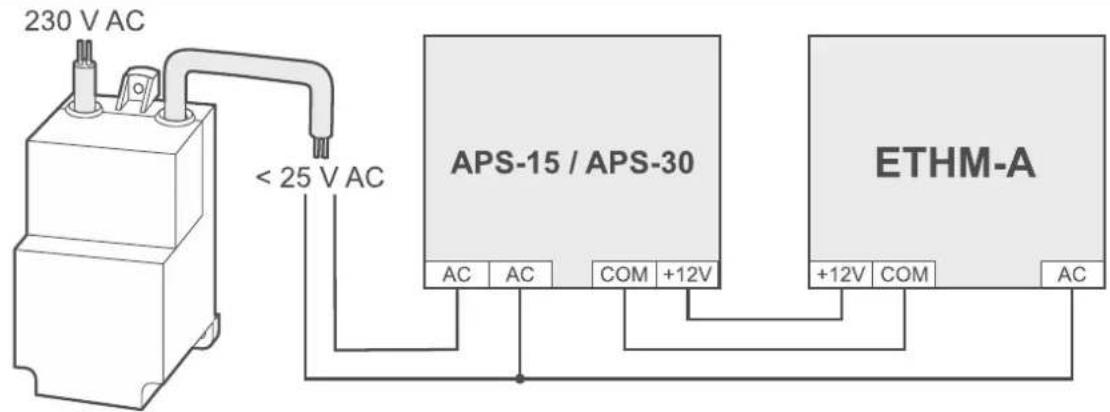
Fig. 6. Example of connecting supply and monitoring AC voltage presence / frequency if the module is powered from SATEL APS-15 / APS-30 power supply unit.
5.5 Connecting the digital temperature sensors (1-Wire)
You can connect up to 8 digital temperature sensors to the 1-Wire bus. The length of wires should not exceed 30 meters. If several sensors are to be connected to the bus, it is recommended that you use the distribution box module (MZ-2 or MZ-3).
SATEL offers the DS-T1 and DS-T2 waterproof temperature sensors. The DS-T1 sensors measure temperatures ranging from -35°C to 60°C, while the DS-T2 – from -40°C to 110°C. They are suitable for indoors or outdoors mounting. The DS-T1 sensors are designed for surface mounting. They can be secured to the mounting surface with adhesives or screws.
The DS-T2 sensors are designed for flush mounting (they are 6 mm in diameter). The DS-T1 / DS-T2 sensor wires are to be connected to the bus terminals in the following manner:
black wire – terminal S1 (common ground),
green wire – terminal S2 (data),
white wire - terminal S3 (power).
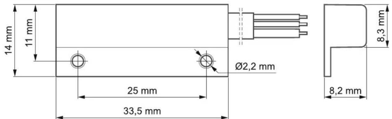
Fig. 7. Dimensions of DS-T1 temperature sensor enclosure.
5.6 Connecting the power supply and starting the module
The module may be powered from the control panel, from an expander with power supply, or from a power supply unit. SATEL offers power supplies (e.g. APS-412), which can be connected to the APS connector on the electronics board.
- Depending on the selected method of module powering, connect the power supply unit to the APS connector or connect the power leads to the +12V and COM terminals
(use flexible conductors with a cross-section of 0.5-0.75 mm or rigid conductors with a cross-section of 1-2.5 mm ^4 ).

Never connect power supply to APS connector and terminals at the same time.
- Power up the module. The module will start up.
6. Configuring
You can configure the module by using a computer with GX Soft program installed. Download the GX Soft program from www.satel.eu.
Required program version: 2.0 (or newer).
Communication between the program and the module is encrypted. You can program the module locally or remotely. Remote programming is only possible after you have configured the network settings of the module (see "Network" p. 21).
6.1 Description of the GX Soft program
Access to the program can be password protected (see “Settings” window” p. 16).
6.1.1 Startup window
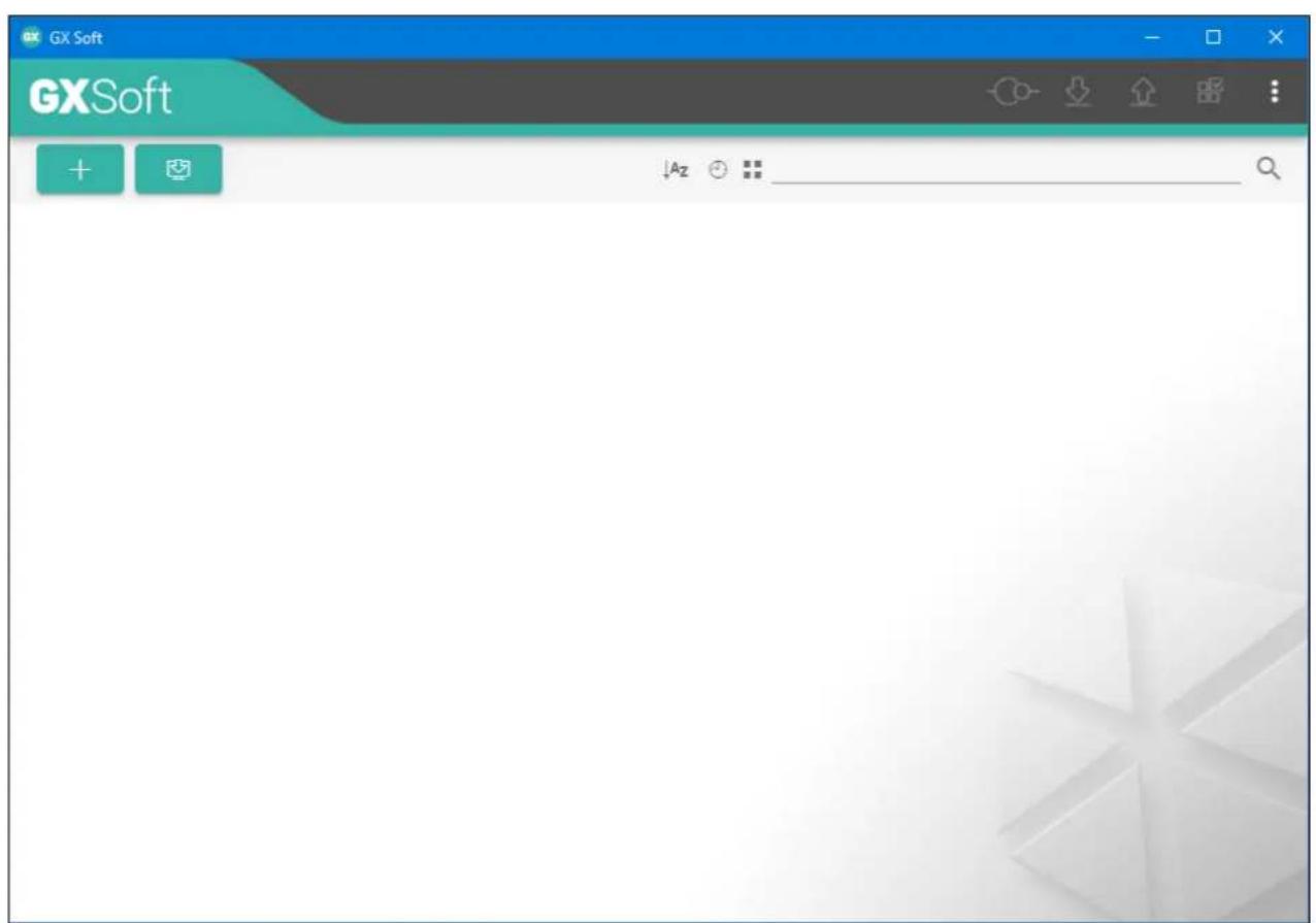
Fig. 8. GX Soft startup window when the program is run for the first time.
In this window you can manage projects created in the GX Soft program.
Buttons
| UPDATE | click to update the GX Soft program. The button is displayed when new program version is available. |
| click to add a new project with module factory default settings. | |
| click to import a project with module settings. | |
| Az | click, if the projects are to be sorted by name (the arrow next to the button indicates whether the projects are displayed from A to Z or from Z to A). This button is displayed if project details are presented in brief version. |
| click, if the projects are to be sorted by the time they were saved to disk (the arrow next to the button indicates whether the projects are displayed in the descending or ascending order). The button is displayed if project details are presented in brief version. | |
| click, if project details are to be presented in brief version. | |
| click, if project details are to be presented in full version. | |
| click to delete the project. The button is displayed when you hover the mouse over the project. |
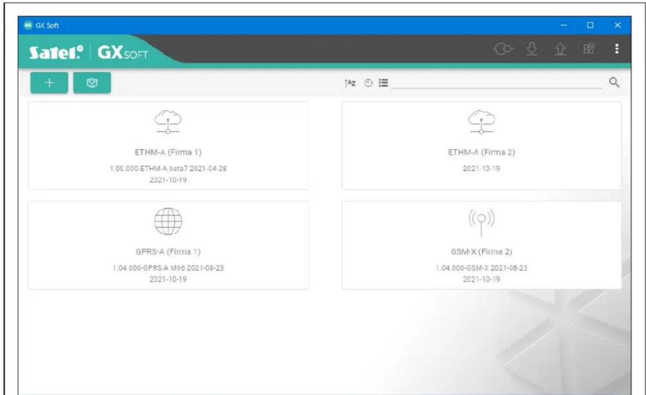
Fig. 9. GX Soft startup window with examples of projects.
Search field
The search field is displayed in the top part of the window. If you want to find a project file:
-
Click on the search field and enter a string of characters included in the file details (e.g. the project name or date created).
-
Click Projects that meet the search criteria will be displayed.

If you want to go back to all projects, click in the search field (this will clear all the characters entered in the field).
Sorting projects
If the project details are presented in full version, click on the selected column header (e.g. "Project name") to sort the list by the data in that column. The symbol indicating the current sorting method ( – ascending, – descending) will be displayed in the column header.
6.1.2 Menu bar in the GX Soft program
The menu bar is displayed in the top part of the program window. Appearance of the menu bar depends on the contents presented in the window.

Fig. 10. The menu bar after establishing connection with the module.
① type of module and firmware version.
② date and time according to the module clock (local time, taking into account the time zones). When you hover the mouse over the field, the time used by the module clock is displayed (Greenwich Mean Time (GMT)).
③ information on the way of communication with the module:
USB – local connection using the module USB port,
SRV – remote connection via Ethernet through the SATEL server,
TCP – remote connection made directly to the module via Ethernet (LAN / WAN).
Click on the text to display information on the connection status.
Buttons
| click to display the list of troubles. | |
| click to update date and time in the module. | |
| click to establish connection to the module. The button is displayed when the program is not connected to the module. | |
| click to disconnect from the module. The button is displayed when the program is connected to the module. | |
| click to read data from the module. | |
| click to write data to the module. If data entered in the program are invalid (e.g. format is wrong or value is outside defined range), a red dot will be displayed on the button: Invalid data will not be written to the module. | |
| click to send a test transmission to the monitoring station. | |
| click to display the status panel. The button is available after connection to the module is established. |

click to display the additional menu.
6.1.3 Side menu
The side menu is displayed on the left side of the program window after you open a project. The buttons displayed in the menu open the tabs used for configuration of the module settings. If data entered in the tab are invalid, a red dot will be displayed on the button.
6.1.4 Status panel
The status panel is displayed after you click on

Status of inputs
input not used. The "OFF" option is selected in the "Type" field (see "Type" p. 22).
√ input in normal status (not violated / threshold not exceeded). Click to bypass the input.
√ input violated / threshold exceeded. Click to bypass the input.
- input bypassed. Click to unbypass the input.
Status of 1-Wire sensors
Q sensor not used (not identified – see: "Identify sensors" p. 26).
√ normal status. Click to bypass the sensor.
√ L or H threshold exceeded. Click to bypass the sensor.
- sensor bypassed. Click to unbypass the sensor.
i sensor trouble.
Status of outputs

output inactive. Click to activate the output.
output active. Click to deactivate the output.
6.1.5 Additional menu
The additional menu is displayed after you click on . Appearance of the menu depends on the contents presented in the window.
Open – click to open a project.
Save – click to save the module data to file.
Export – click to export the file with module data.
Connection - click to open the "Connection" window.
Settings – click to open the "Settings" window.
About – click to display information about the program.
"Connection" window
In the window, you can select how to establish connection with the module:
- if the module is to be programmed from a computer connected to the module USB port, click "USB",
- if the module is to be programmed through SATEL server via Ethernet, click "SATEL SERVER",
- if the module is to be programmed via Ethernet, directly from a computer in the same local network as the module, click "LAN",
- if the module is to be programmed via Ethernet, directly from a computer in a public network, click "WAN".
Module key – a string of characters for identification of the module. It must be identical to that programmed in the module (see "Communication" p. 28). Click 🔒 to view the key.
USB
A list of modules connected to the computer USB port is displayed in the tab. Select from the list a module that you want to connect to.
![Connection Module key 0 / 16 USB SATEL SERVER LAN WAN [001B9C010029] ETHM-A OK CANCEL](/content/2026/05/1065444/images/b9d63b4984e21e59927233f0ebe9a3cecd40ce519c3da2ad2dd7a9e4959b1987.jpg)
Fig. 11. "Connection" window: "USB" tab.
SATEL SERVER
MAC – module hardware address.
ID – individual identification number for the purposes of communication through the SATEL server. The number is assigned automatically by the SATEL server during the first connection to the server (before the number is assigned, "F" characters are displayed). Click to view the number.
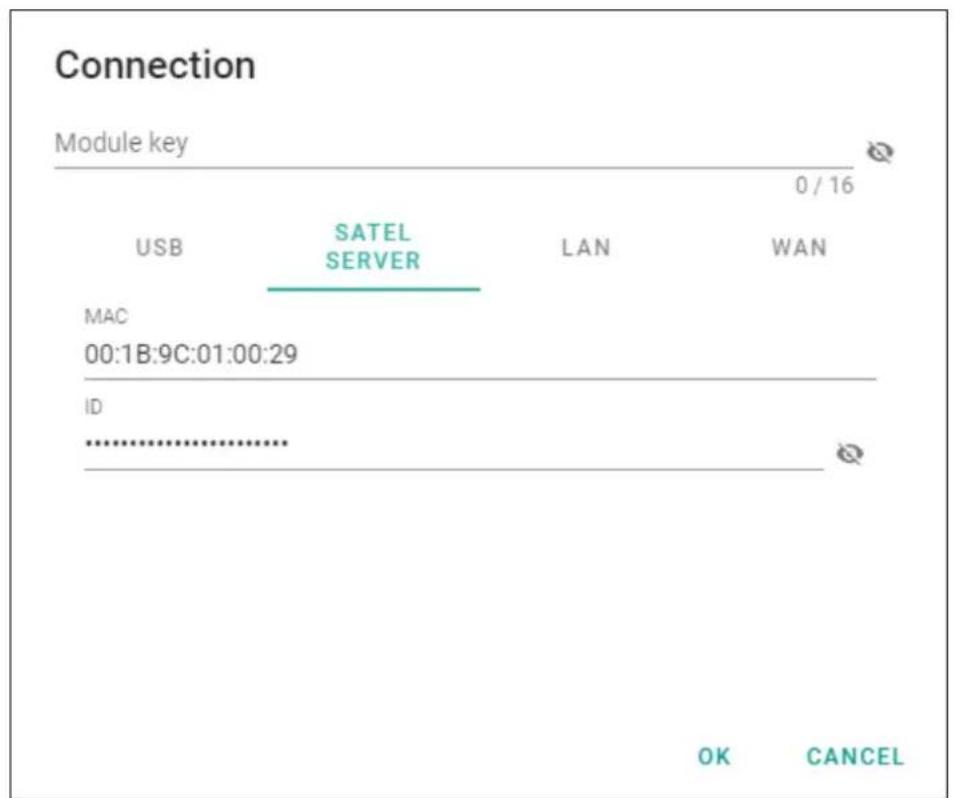
Fig. 12. "Connection" window: settings for establishing connection through SATEL server.
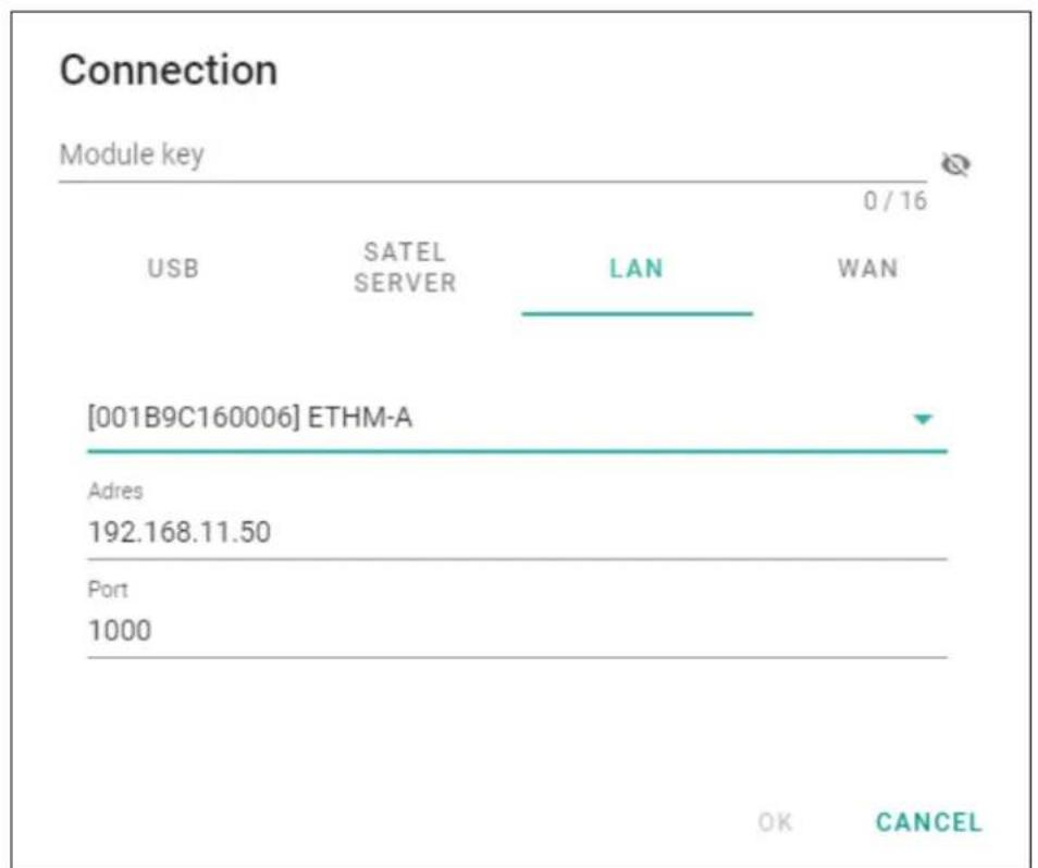
LAN
line
Connection Module key | Module | Key | Value | | :--- | :--- | :--- | | 0 / 16 | USB | Not labeled | | SATEL SERVER | | Not labeled | | LAN | | Not labeled | | WAN | | Not labeled | | [001B9C160006] ETHM-A | Adres | 192.168.11.50 | | Port | | 1000 | OK CANCELFig. 13. "Connection" window: connection settings in the local network.
You can select a module from the list of modules found by the GX Soft program in the local network or manually enter the settings required to establish connection. Only the modules in which the “Direct connection” option is enabled are available on the modules list (see “Communication” p. 28).
[Module] – list of modules found by the GX Soft program in the local network.
Address – module address in the local network.
Port – number of the port used for communication between the GX Soft program and the module.
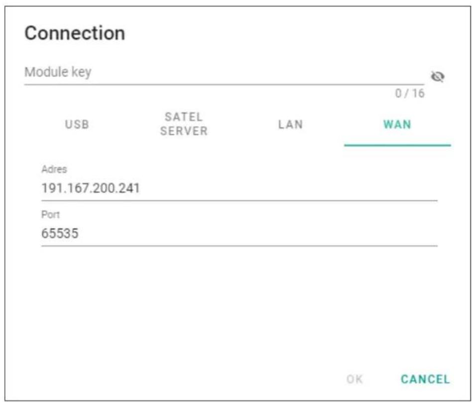
WAN
other
Connection Module key | Module | 0 / 16 | | :--- | :--- | | USB | SATEL SERVER LAN WAN | | Adres | 191.167.200.241 | | Port | 65535 | OK CANCELFig. 14. "Connection" window: connection settings in the wide area network.
Address – module public address.
Port – number of the port used for communication between the GX Soft program and the module.
Buttons
OK – click to confirm the changes.
Cancel – click to close window without saving changes.
6.1.6 "Settings" window
GX Soft password – if you want to protect the program against unauthorized access, enter the password. Click to view the password.
Confirm GX Soft password – enter the password again. Click 🔒 to view the password.
Application language – you can select the language of the program.
Buttons
Delete GX Soft password – click to delete the password.
OK – click to save changes.
Cancel – click to close window without saving changes.
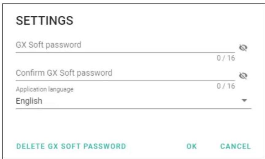
Fig. 15. "Settings" window.
6.2 Establishing communication with the module

Establishing connection is possible, if an identical "Module key" has been programmed in the module and in the program, except for the module with factory settings.
6.2.1 Local connection
- Connect the module USB port with the computer USB port.
- In the startup window, open the file with module data (a file with default settings or a previously saved file).
- In the "Connection" window, "USB" tab, select the module that you want to connect to (see ""Connection" window").
- Click on the menu bar.
- A window will open with information that connection has been established and you will be asked if you want to read the data.
- Click "Yes" if you want to read the data stored in the module.
6.2.2 Remote connection: SATEL server

The “Connect to GX Soft” option must be enabled in the module (see “Communication” p. 28). By default, this option is disabled.
- In the startup window, open the file with module data (a file with default settings or a previously saved file).
- In the "Connection" window, "SATEL SERVER" tab, configure the settings required to establish connection through the SATEL server (see "Connection" window" p. 13).
- Click on the menu bar.
- A window will open with information that connection has been established and you will be asked if you want to read the data.
- Click "Yes" if you want to read the data stored in the module.
6.2.3 Remote connection: direct connection in the local network

The “Direct connection” option must be enabled in the module (see “Communication” p. 28). By default, this option is disabled.
- In the startup window, open the file with module data (a file with default settings or a previously saved file).
- In the "Connection" window, "LAN" tab, select the module that you want to connect to or manually enter the settings required to establish connection with the module (see "Connection" window" p. 13).
- Click on the menu bar.
- A window will open with information that connection has been established and you will be asked if you want to read the data.
- Click "Yes" if you want to read the data stored in the module.
6.2.4 Remote connection: direct connection in the public network

The “Direct connection” option must be enabled in the module (see “Communication” p. 28). By default, this option is disabled.
The computer running the GX Soft program must have a public IP address.
- In the startup window, open the file with module data (a file with default settings or a previously saved file).
- In the "Connection" window, "WAN" tab, configure the settings required to establish connection through the WAN network (see "Connection" window" p. 13).
- Click on the menu bar.
- A window will open with information that connection has been established and you will be asked if you want to read the data.
- Click "Yes" if you want to read the data stored in the module.
6.3 Project
In this tab you can enter data for easier identification of the project created.
Project name – individual name of the project.
Owner – name of the project owner.
Address – address data of the project owner.
Contact telephone – contact telephone number of the project owner.
Created by – name of the project author.
Created at – date when the project was created.
Updated at – date when the project was last updated.
Synchronized at – date when the data from the module were last written / read.
Notes – additional information / notes stored in the project.
Note (stored in module) – additional information / notes stored in module memory.
Firmware version – module firmware version: number and date.
MAC – module hardware address.
ID – individual identification number of the module for the purposes of communication through the SATEL server (assigned automatically by the SATEL server). Click to view the number.

- click to open the window in which the QR code is displayed. The QR code contains information required when configuring settings of communication through the SATEL
server. You can read the QR code by using a mobile device or export to PNG file and transmit to the users. The QR code facilitates configuring the GX Control application settings.
Factory settings – click to restore module factory settings. A message box will be displayed in which you must confirm your intention to restore the factory settings of the module.
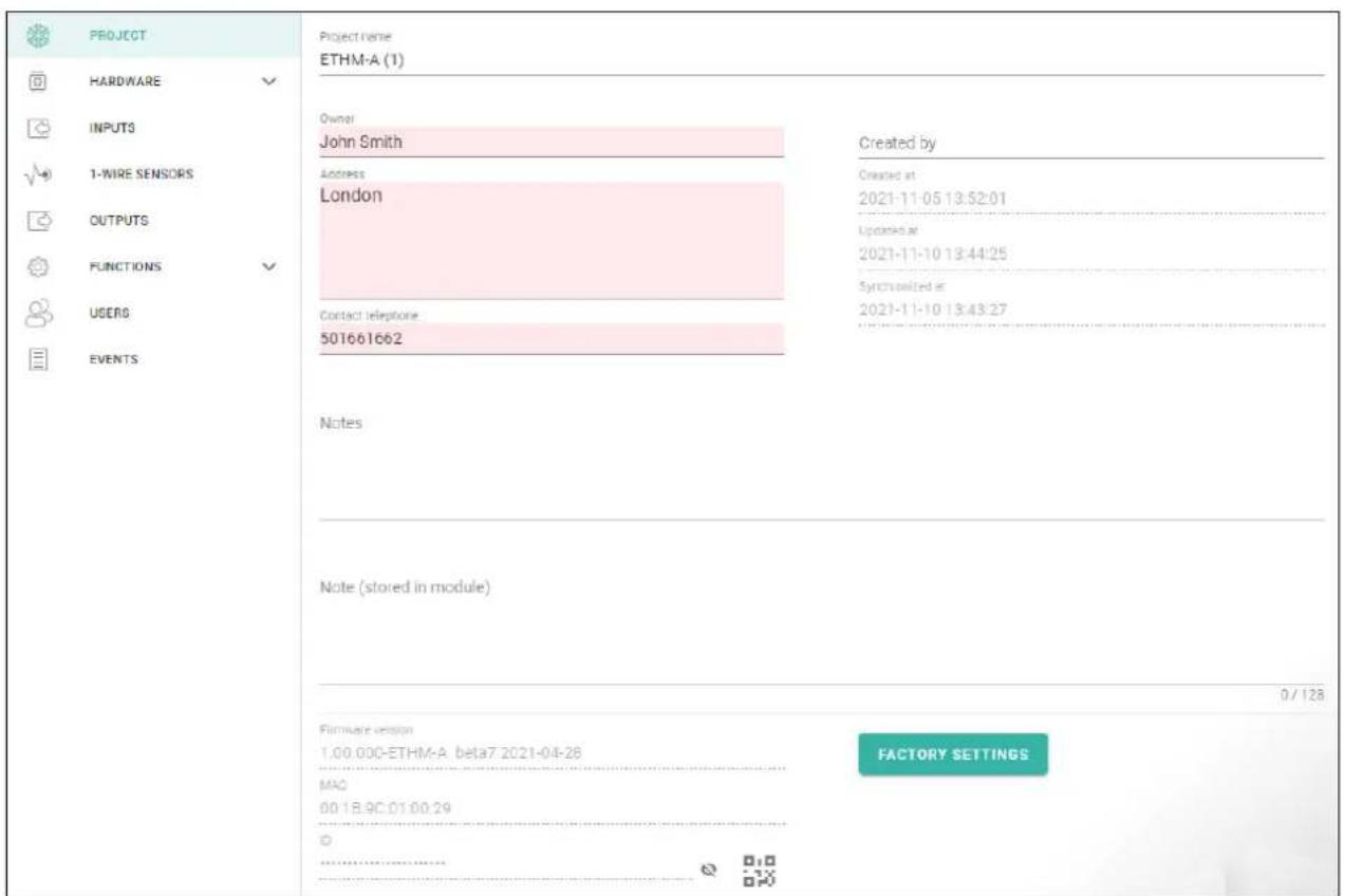
Fig. 16. "Project" tab.
6.4 Hardware
6.4.1 Mainboard
Module language – you can select the default language to be used for any descriptions in the module. Names of inputs, 1-Wire sensors, outputs, users and descriptions of events in the GX Soft program and the GX Control application will be displayed in the language selected, regardless of the language version of the program (see “Settings” window” p. 16) and the application.
E-mail settings
SMTP server – address of outgoing mail server.
SMTP port – number of outgoing mail port.
Login name – name of the e-mail account used for authorization by the SMTP server (login to e-mail account).
Password – the password used for authorization by the SMTP server.
Encryption – outgoing e-mail encryption protocol:
SSL/TLS – outgoing mail is encrypted using the SSL/TLS protocol.
START TLS – outgoing mail is encrypted using the STARTTLS protocol.
NONE – outgoing mail is not encrypted.
Subject – subject of the e-mail message. It will be inserted in each e-mail message to be sent.
Sender e-mail address – e-mail address which will be inserted in the outgoing e-mail message as the sender address. If this field is blank, the name of e-mail account will be treated as the sender address.
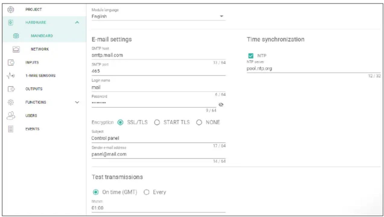
Fig. 17. "Mainboard" tab.
Test transmissions
On time (GMT) – select this option if the test transmission is to be sent every day at a specified time. Define the hour and minute.
Every – select this option if the test transmission is to be sent at specified time intervals. Define every how many days, hours and minutes.

The module will send a test transmission if, when configuring the module events distribution, you define the monitoring station to which a test transmission is to be sent (see “Module events distribution” p. 34).
Time synchronization

The module uses the Greenwich Mean Time (GMT), not the local time (the time zones are not taken into account).
NTP – if this option is enabled, the module clock is synchronized with the time server.
NTP server – time server address. The field is available if the "NTP" option is enabled. You can enter the IP address or domain name.
6.4.2 Network
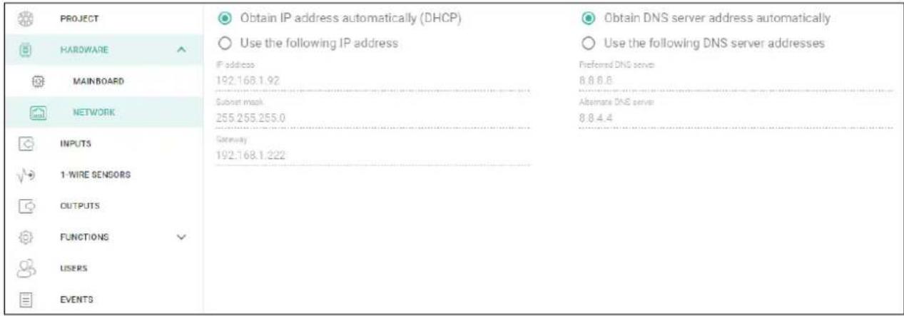
Fig. 18. "Network" tab.
Obtain IP address automatically (DHCP) – select this option if module IP address, subnet mask and gateway are to be downloaded automatically from the DHCP server.
Use the following IP address – select this option if you want module IP address, subnet mask and gateway to be entered manually.
IP address – module IP address.
Subnet mask – the mask of the subnet in which the module is working.
Gateway – IP address of the network device through which the other devices in the local network can communicate with devices in other networks.
Obtain DNS server address automatically – select this option if the module is to download IP address of the DNS server automatically from the DHCP server.
Use the following DNS server addresses – select this option if you want the IP address of DNS server to be entered manually.
Preferred DNS server / Alternate DNS server – IP address of the DNS server which is to be used by the module.
6.5 Inputs
6.5.1 Status

input not used. The "OFF" option is selected in the "Type" field (see "Type" p. 22).

input in normal status (not violated / threshold not exceeded). Click to bypass the input.

input violated / threshold exceeded. Click to bypass the input.

input bypassed. Click to unbypass the input.
The buttons are displayed when the program is connected to the module. If the input has been programmed as analog one, the value of input voltage or the value of physical quantity recorded by the sensor connected to the input (e.g. air humidity) is displayed under the button. The physical quantity is displayed when the voltage scaling to the value recorded by the sensor has been programmed for the input (see "Scaling" p. 24).
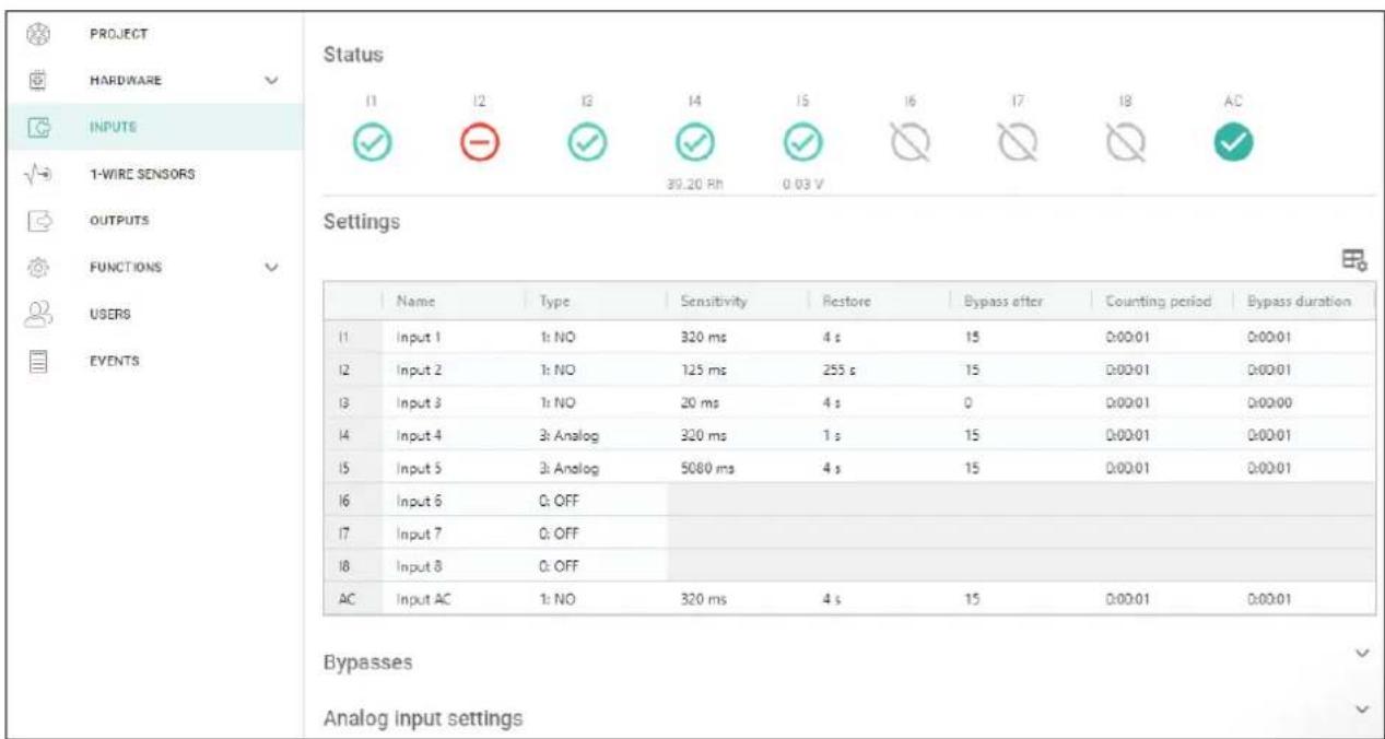
Fig. 19. "Inputs" tab.
6.5.2 Settings

- click to show the table options. The options enable you to hide / show the selected columns in the table and to fit the columns to its content or to the width of the window.
Name – individual name of the input (up to 16 characters).
Type – you can program the input as:
OFF – not used.
NC – digital, normally closed.
NO – digital, normally open.
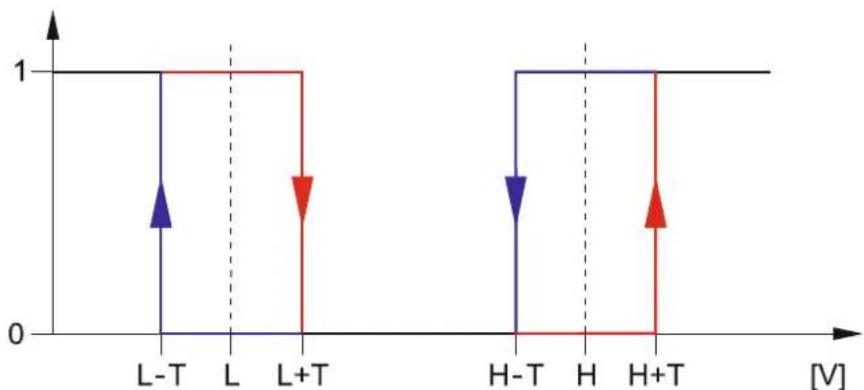
Analog - voltage measurement from 0 to 16.56V . Fig. 20 shows how the analog input works.

If the AC input is to be used to monitor the presence of AC voltage, program it as NC or NO. If the AC input is to be used to measure AC voltage frequency, program it as analog.
Sensitivity – time during which:
- the NC type digital input must be disconnected from the ground so that the module can register the input violation,
- the NO type digital input must be shorted to ground so that the module can register the input violation,
- the analog input value must remain below the L threshold (minus tolerance) or above the H threshold (plus tolerance) so that the module can register a threshold exceeding (violation) (see Fig. 20).
You can program from 20 to 5100 ms (every 20 ms).
Restore – time during which:
- the NC type digital input must be again shorted to ground so that the module can register input restore (end of violation),
- the NO type digital input must be again disconnected from the ground so that the module can register input restore (end of violation), - the analog input value must remain above the L threshold (plus tolerance) or below the H threshold (minus tolerance) so that the module can register input restore (end of violation).
Defining the time will reduce the number of sent transmissions. You can program from 1 to 255 seconds.
Bypass after – the number of violations / threshold exceedings after which the input will be automatically bypassed (the input is bypassed after restore). You can program from 0 to 15. Value 0 means no bypass.
Counting period – the time after which the counter of violations / exceedings programmed for the given input will be reset. You can program from 0 to 24 hours. Value 0 means that the violations / exceedings will be counted without time limits.
Bypass duration – if the input is to be automatically bypassed for a specific time period, enter the time here. You can program from 0 to 24 hours. Value 0 means that the given input will be bypassed until unbypassed by the user.
6.5.3 Bypasses

– click to show the table options. The options enable you to hide / show the selected columns in the table and to fit the columns to its content or to the width of the window.
You can indicate the input which, in the event of violation / threshold exceeding, will bypass other inputs of the module. When the input is restored, the bypassed inputs will be unbypassed. Each of the module inputs can bypass the other 8 inputs. The table rows present the “Bypassing” inputs, and the columns present the “Bypassed” inputs. If you want the input violation / threshold exceeding to bypass another module input, select the field at the intersection of the corresponding row and column.
6.5.4 Analog input settings

- click to show the table options. The options enable you to hide / show the selected columns in the table and to fit the columns to its content or to the width of the window.
Name – individual name of the input.
L Threshold – the lower threshold for analog input. Drop of the input value below the threshold (minus tolerance) means the threshold is exceeded (i.e. input is violated). If you enter no value, the threshold will not be monitored.
H Threshold – the upper threshold for analog input. Rise of the input value above the threshold means the threshold is exceeded (i.e. input is violated). If you enter no value, the threshold will not be monitored.
Tolerance – value by which response of the analog input is delayed. The module will register the threshold exceeding if the input value drops below the L threshold minus tolerance or rises above the H threshold plus tolerance. The module will register the input restore if the input value rises above the L threshold plus tolerance or drops below the H threshold minus tolerance.
Unit - unit of the physical quantity recorded by the sensor connected to the analog input.
line
| Voltage | Response | | ------- | -------- | | L-T | 0 | | L | 1 | | L+T | 0 | | H-T | 0 | | H | 1 | | H+T | 0 |Fig. 20. Analog input operation. 0 – normal status (no violation),
1 – threshold exceeded (violation), L-T – lower threshold minus tolerance, L – lower threshold, L+T – lower threshold plus tolerance, H-T – upper threshold minus tolerance, H – upper threshold, H+T – upper threshold plus tolerance.

Values in the “L Threshold”, “H Threshold” and “Tolerance” fields may go beyond the range of 0...16.56, if the voltage value on the analog input is scaled to the physical quantity recorded by the sensor (see “Scaling” p. 24). If this is the case, units other than volts (V) may be used.
[Scaling]
Define how the voltage value on analog input will be scaled to the physical quantity that is recorded by the sensor connected to the input. Use the linear characteristic from the sensor installation manual. This characteristic illustrates dependence between the sensor output voltage and the physical quantity recorded by the sensor (see Fig. 21).
P1 / P2 – enter the voltage value (X1 / X2) and the corresponding value of the physical quantity (Y1 / Y2) for two points on the linear characteristic of the sensor (see the example in Fig. 21, where: P1: 0.75 V -> 0% Rh and P2: 1.5 V -> 40% Rh).
![Satel ETHM-A - [Scaling] - 1](/content/2026/05/1065444/images/9b52e145a3684b0aae85a16f9f5de8de6bf97e336db193b5a959ee9f8ee70d0f.jpg)
line
| Point | X [V] | Y [%Rh] | |-------|-------|---------| | P1 | 0.7 | 0 | | P2 | 1.5 | 40 |Fig. 21. Example of the linear characteristic of air humidity sensor. X – voltage on the sensor output [V], Y – relative humidity [% Rh].
6.6 1-Wire sensors
The 1-Wire bus can handle up to 8 digital temperature sensors. The way the 1-Wire sensors are being handled by the module is much the same as in the case of sensors connected to the analog inputs (see Fig. 20).
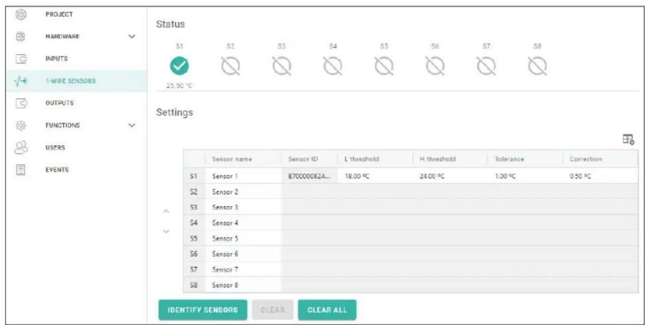
Fig. 22. "1-Wire sensors" tab.
6.6.1 Status
sensor not used (not identified – see “Identify sensors” p. 26).
√ normal status. Click to bypass the sensor.
√ L or H threshold exceeded. Click to bypass the sensor.
- sensor bypassed. Click to unbypass the sensor.
i sensor trouble.
The buttons are displayed when the program is connected to the module. Temperature recorded by the given sensor is displayed under the button (plus / minus correction value – see "Correction").
6.6.2 Settings
- click to show the table options. The options enable you to hide / show the selected columns in the table and to fit the columns to its content or to the width of the window.
Sensor name – individual name of the sensor connected to the bus (up to 16 characters).
Sensor ID – individual identification number of the sensor. The number is stored in the sensor memory. It will be read by the module after starting the sensor identification function.
L threshold – the lower temperature threshold for the sensor. If the temperature drops below the defined value (minus tolerance), the module will register a threshold exceeding. You can program temperatures ranging from -55^ to 125^ . If no value is defined, the temperature threshold will not be monitored.
H threshold – the upper temperature threshold for the sensor. If the temperature rises above the defined value (plus tolerance), the module will register a threshold exceeding. You can program temperatures ranging from -55^ to 125^ . If no value is defined, the temperature threshold will not be monitored.
Tolerance – value by which response of the module is delayed. The module will register the threshold exceeding if the temperature drops below the L threshold minus tolerance or rises above the H threshold plus tolerance. The module will register the restore to normal status if the temperature rises above the L threshold plus tolerance or drops below the H threshold minus tolerance.
Correction - the value by which the sensor-recorded temperature is corrected by the module. You can program any value from -55^ to 125^ . The positive value is added to and the negative one is subtracted from the recorded temperature.
Buttons
^ / ∨ click to change position of the sensor on the list.
Identify sensors – click to run the identification function for sensors connected to the bus. The module will read the ID numbers of connected sensors. The sensor ID number will be displayed in the “Sensor ID” field.

If sensors which have no designation are to be connected to the bus, connect them one at a time and run the identification function. Thus, you will be able to describe them accordingly yourself.
The sensor will only be supported by the module after running the identification function.
Clear – click to delete selected sensor.
Clear all – click to delete all sensors.
6.7 Outputs
6.7.1 Control

output inactive. Click to activate the output.

output active. Click to deactivate the output.
The buttons are displayed when the program is connected to the module.
6.7.2 Settings

– click to show the table options. The options enable you to hide / show the selected columns in the table and to fit the columns to its content or to the width of the window.
Name - individual name of the output (up to 16 characters).
Operating time – time during which the output is active. Entering “0” will keep the output active until deactivated by the user.
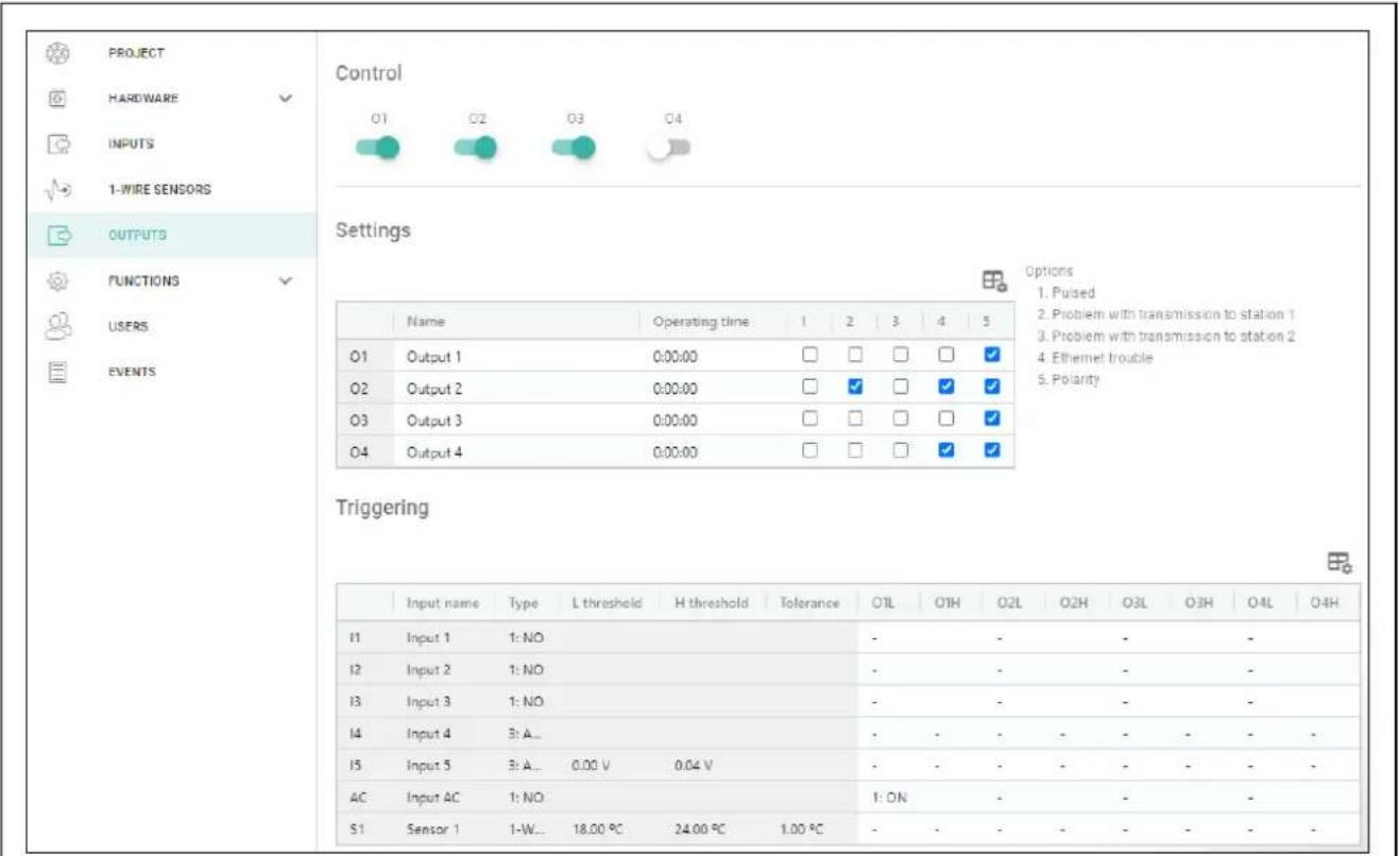
Fig. 23. "Outputs" tab.
Options
Pulsed – if this option is enabled, the output is pulsating when it is active. The option does not apply to relay outputs.
Problem with transmission to station 1 / 2 – if this option is enabled, the output will be active in the case of any problem with transmitting events to the monitoring station 1 / 2.
Ethernet trouble – if this option is enabled, the output is active in case of any trouble with the Ethernet.
Polarity – the option defines how the output will operate (see table below). If this option is disabled, the output is inverted.
| Output | ||
| option enabled (normal polarity) | option disabled (reverse polarity) | |
| output inactive | disconnected from ground | shorted to ground |
| output active | shorted to ground | disconnected from ground |
Table 1. Mode of output operation depending on the "Polarity" option.
6.7.3 Triggering

- click to show the table options. The options enable you to hide / show the selected columns in the table and to fit the columns to its content or to the width of the window.
Define whether and how the inputs / 1-Wire sensors are to control the outputs. The table rows present the inputs / 1-Wire sensors, and the columns O1 L/H...O4 L/H present the outputs of the module. If you want the input violation / threshold exceeding to change the output status, select one of the available options by checking the box at the intersection of the corresponding row and column:
- - input / sensor does not control the output.
1: ON – violation of the input / threshold exceeding will activate the output.
2: OFF – violation of the input / threshold exceeding will deactivate the output.
3: ON FOR TIME – violation of the input / threshold exceeding will activate the output for the time programmed in the “Operating time” field (see p. 26).
4: TOGGLE – violation of the input / threshold exceeding will switch the output to its opposite status.
5: FOLLOW INPUT – violation of the input will activate the output, and restoration of the input will deactivate the output.
i
The table presents only those inputs and 1-Wire sensors that are in use.
For the analog input and for the 1-Wire sensor, the output control method is to be defined separately for each of the defined thresholds.
Inputs / 1-Wire sensors
The “Type”, “L Threshold”, “H Threshold” and “Tolerance” fields present information about the settings of inputs / 1-Wire sensors. For description of parameters, see sections “Inputs” (p. 22) and “1-Wire sensors” (p. 25).
6.8 Communication
Module key – a string of characters for identification of the module. You can enter up to 16 alphanumeric characters (digits, letters and special characters). You can use spaces, but at least one character must be different from space. Do not program the same key for different modules. Communication between the GX Soft program and the module is possible if the keys in the program and the module are identical.
Module – type and version of the module firmware.
MAC – module hardware address.
ID – individual identification number of the module for the purposes of communication through the SATEL server (assigned automatically by the SATEL server). Click to view the number.
IP address – module IP address.
Subnet mask – the mask of the subnet in which the module is working.
Gateway – IP address of the network device through which the other devices in the local network can communicate with devices in other networks.
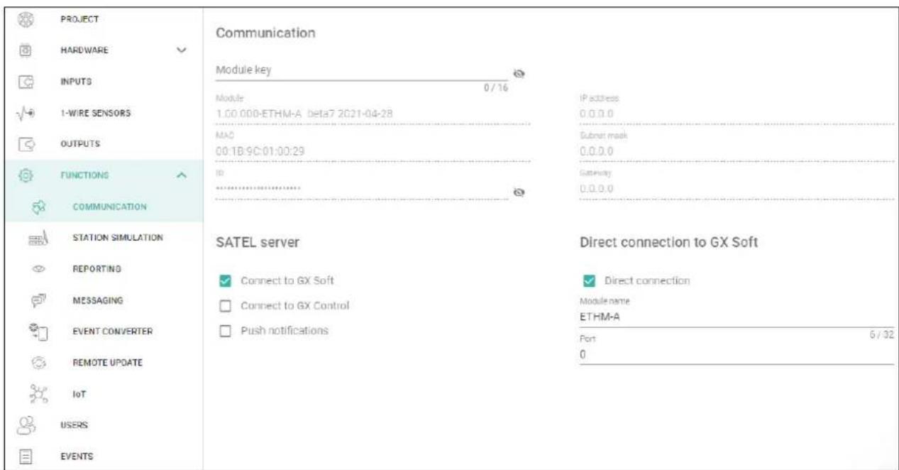
Fig. 24. "Communication" tab.
6.8.1 SATEL server
Connect to GX Soft – if this option is enabled, it is possible to establish connection between the GX Soft program and the module through the SATEL server.
Connect to GX Control – if this option is enabled, it is possible to establish connection between the GX Control application and the module through the SATEL server.
Push notifications – if this option is enabled, the GX Control application can provide information about events by means of push notifications.
6.8.2 Direct connection to GX Soft
Direct connection – if this option is enabled, it is possible to establish direct connection between the GX Soft program and the module via Ethernet.
Module name – individual name of the module for easier identification of the module when it works in the same local network as the computer with GX Soft program.
Port – number of the TCP port used for direct communication between the module and the computer with GX Soft program. You can enter values from 0 to 65535 (0=disabled).
6.9 Station simulation
Station simulation – if this option is enabled, the module can receive event codes from the control panel (the module simulates the monitoring station).
Events buffering – if this option is enabled, each event received by the module from the control panel is written to the module event log and confirmed immediately on receipt. If the option is disabled, events from the control panel will not be written to the module event log, and the received event will only be confirmed after the module receives acknowledgement of the event receipt by the monitoring station.
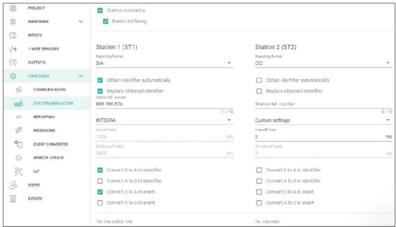
Fig. 25. "Station simulation" tab.
Station 1 (ST1) / Station 2 (ST2)
Reporting format – the format in which event codes are sent to the monitoring station. The following formats are available: SIA, CID, AdemcoExpress, Sil.Knight/Ademco slow, Radionics 1400Hz, Radionics 1400Hz with parity.
Obtain identifier automatically – enable this option, if the control panel identifier is to be used by the module for module's own test transmissions. Enabling this option is not recommended when several identifiers are used by the control panel for reporting purposes (when sending a code of module related event, the identifier used last time by the control panel will be used, which means that events related to the module can be sent with different identifiers).
Replace obtained identifier – enable this option, if the module, after receiving the event code from the control panel and before sending it to the monitoring station, is to replace the identifier in the event code with characters programmed in the “Module identifier” field (see “Reporting” tab p. 32).
Station tel. number – if this number is dialed by the control panel connected to the TIP and RING terminals, the module will be receiving the event codes. If the “Reporting” option (p. 31) is enabled in the module, the received codes can be retransmitted by the module to the monitoring station. Define how they should be sent – see “Server connection settings” p. 33.

If you enter three “#” characters instead of a telephone number, the number verification will be disabled. The module will be receiving the event codes when the control panel has dialed any number.
[Kiss-off] – the way of configuring the "Kiss-off time" and "SIA kiss-off delay" parameters.
Custom settings – you can configure the parameters manually.
Typical settings – the parameters are configured automatically, as required by the selected reporting format (“Reporting format”).
[control panel] – the parameters are configured automatically, as required by the selected alarm control panel.
Kiss-off time – duration of the signal generated by the module to confirm receipt of the event from the control panel. The value entered must be suitable for the reporting format selected in the control panel. You can program from 0 to 9999 ms (default: 0 ms). Programming value 0 means that the kiss-off time will be programmed according to the standard of the format selected in the control panel.
SIA kiss-off delay – the time by which the acknowledgment of receipt by the module of the event in SIA format will be delayed. The value entered must be suitable for the control panel settings. You can program from 0 to 9999 ms (default: 0 ms). Programming value 0 means that the time of kiss-off delay will be programmed according to the SIA format standard.
[Conversion]
For events in Ademco Express and Contact ID format, you can select the following options:
Convert 0 to A in identifier – if this option is enabled, the module will convert 0 into A in the identifier of event sent to the monitoring station.
Convert A to 0 in identifier – if this option is enabled, the module will convert A into 0 in the identifier of event sent to the monitoring station.
Convert 0 to A in event – if this option is enabled, the module will convert 0 into A in the code of event sent to the monitoring station.
Convert A to 0 in event – if this option is enabled, the module will convert A into 0 in the code of event sent to the monitoring station.
Information
Tel. line status – information about current handling of the telephone line output.
Tel. line data – information about the data currently being received from the control panel.
6.10 Reporting
i
If the “Events buffering” (p. 29) option is not enabled, events received by the module from the control panel have a priority over events generated by the module and their codes are sent to the monitoring station first.
Reporting – if this option is enabled, the module can send event codes to the monitoring station. The option applies to the events received by the module from the alarm control panel and the events generated by the module.
Reporting mode – the way of sending event codes to the monitoring stations:
Only Station 1 – the event codes are only sent to station 1.
Only Station 2 – the event codes are only sent to station 2.
Station 1 and Station 2 – the event codes are sent to both stations (the module must receive acknowledgement of the receipt of the code from both monitoring stations).
Station 1 or Station 2 – the module will make an attempt to send the event code to station 1 and, if unsuccessful, to station 2.
Station 2 takes over link test from station 1 – if this option is enabled when the module fails to connect to the monitoring station 1 during the link test, the module will test link to the monitoring station 2. The option can be enabled if the SIA-IP format is selected for both monitoring stations in the "IP format / protocol" field (see p. 32).
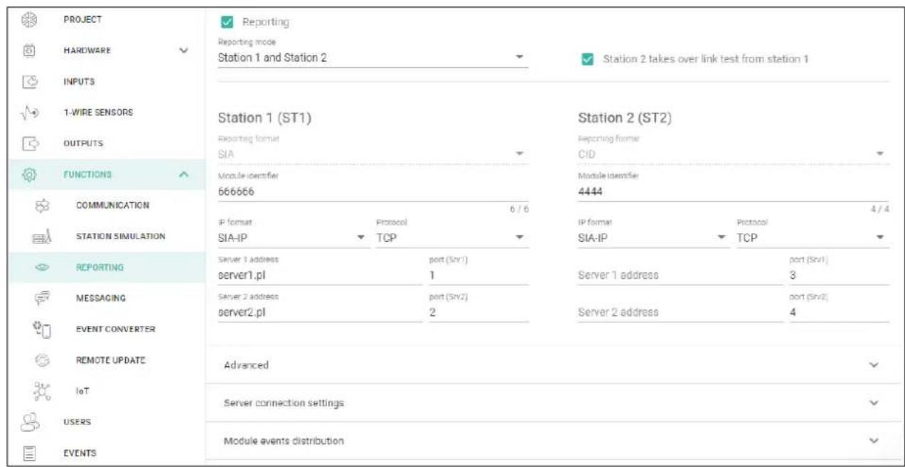
Fig. 26. "Reporting" tab.
Station 1 (ST1) / Station 2 (ST2)
Reporting format – the format in which event codes are sent to the monitoring station. The following formats are available: SIA, CID, 4/2. If the “Station simulation” option (p. 29) is enabled in the module, the field cannot be edited. If this is the case, information about the format selected in the “Station simulation” tab (see “Reporting format” p. 30) is displayed in the field. If “AdemcoExpress”, “Sil.Knight/Ademco slow”, “Radionics 1400Hz” or “Radionics 1400Hz with parity” format is used, information that the codes are sent in 4/2 format is displayed.
Module identifier – a string of characters that enables the monitoring station to define from where the events are being sent. For the Contact ID format, it consists of 4 hexadecimal characters (digits or letters from A to F). For the SIA format, it consists of 6 hexadecimal characters (digits or letters from A to F), including a 2-character prefix.
IP format – select the format: SATEL or SIA-IP (SIA DC-09 standard).
Protocol – select the protocol: TCP or UDP.
Server 1/2 address – address of the monitoring station. You can enter the IP address or domain name.
port (Srv1)/(Srv2) – number of the port used for communication between the module and the monitoring station during reporting. You can enter a value from 0 to 65535.
Advanced
SATEL station key – a string of characters for encrypting the sent data. You can enter up to 12 alphanumeric characters (digits, letters and special characters). If you want to enter 24 hexadecimal characters (digits or letters from A to F), enable the “hex” option.
ETHM key – a string of characters, which is used to identify the module for the purpose of reporting. You can enter up to 5 alphanumeric characters (digits, letters and special characters). If you want to enter 10 hexadecimal characters (digits or letters from A to F), enable the “hex” option.
SIA-IP account number – a string of characters used to identify the module for the purpose of reporting in SIA-IP format. You can enter up to 16 hexadecimal characters (digits or letters from A to F).
SIA-IP key – a string of characters for encrypting data sent in the SIA-IP format. You can enter up to 16 alphanumeric characters (digits, letters and special characters). If you want to enter 32 hexadecimal characters (digits or letters from A to F), enable the "hex" option.
Account prefix (L) / Receiver number (R) – a string of characters used to identify the module for the purpose of reporting in SIA-IP format. The parameters enable you to expand the list of attributes used to identify the module. You can enter up to 6 hexadecimal characters (digits or letters from A to F).
Both servers link test – if this option is enabled, the module will test link to both servers of the monitoring station. The option applies to SIA-IP format.
Supervision every – in the case of reporting in the SIA-IP format, an additional transmission can be sent at specified intervals to check link with the monitoring station. You can program a number of days, hours, minutes and seconds between the transmissions. Entering zeros only means that no additional transmission will be sent.
Server 2 takes over link test from server 1 – if this option is enabled when the module fails to connect to the monitoring station server 1 during the link test, the module will test link to the server 2 (according to settings provided for testing the server 1). The option applies to SIA-IP format.
Transmission period acc. to – the way of configuring the “Supervision every (Server 1)” and “Supervision every (Server 2)” parameters.
DP1 / DP2 / DP3 / DP4 – the parameters are configured automatically, as required by the EN 50136-1 standard for Dual Path Reporting.
OTHER – you can configure the parameters manually.
The options are available when the "Both servers link test" option is enabled.
Supervision every (Server 1) / Supervision every (Server 2) – number of days, hours, minutes and seconds between the tests of link to servers. The fields are displayed when the “Both servers link test” option is enabled.
SIA-IP options
Encrypt – if this option is enabled, the data being sent are encrypted, and additionally the date and time are sent with the event code (the monitoring station can program the date and time in the module).
Send timestamp – if this option is enabled, the date and time are sent with the event code (the monitoring station can program the date and time in the module). It is available, when the “Encrypt” option is disabled.
Send MAC address – if this option is enabled, the MAC address is sent together with the event code.
Server connection settings
Srv1 / Srv2 – if this option is enabled, the module will try to send the event code to the given server. If you select sending to two servers, a successful send of event code to the server will terminate the procedure. An exception is the test transmission if option “Send test transmission to both servers” is enabled. In such case the module will try to send the event code to both servers.
Timeout 1 / Timeout 2 – the maximum time during which the module will try to send the event code to the selected server. If the event code is not sent during that time, the module will switch over to the other server.
Suspend time – the time for which reporting will be suspended after failed attempts to send an event code to the selected servers. The module will resume the attempt to establish connection with the monitoring station after this time expires or when a new event occurs. Up to 30 minutes can be programmed (by default: 1).
Number of retries – the number of unsuccessful retries to send the event code to the station server selected for reporting, after which the module will make an attempt to send the event to the other server.
Send test transmission to both servers – if this option is enabled, the test transmission will be sent to both monitoring station servers. If this option is disabled, a successful send of event code to one monitoring station server address will terminate the procedure.
6.10.1 Module events distribution
Define which events are to be sent to the monitoring station 1 and which to the monitoring station 2. The code of a module related event will be sent to the monitoring station only when the selection box corresponding to the given event is checked. Adjust the distribution of events to the code sending method selected in the “Reporting mode” field (see p. 31).
6.10.2 Event codes
- click to show the table options. The options enable you to hide / show the selected columns in the table and to fit the columns to its content or to the width of the window.
For each event generated by the module, you can define codes in three formats:
4/2 [Ademco Express, Sil.Knight/Ademco slow, Radionics 1400Hz, Radionics 1400Hz with parity] – enter 2 characters (digits or letters from A to F). The event code must be consistent with the code programmed for the event in the monitoring station.
SIA – enter event code consistent with SIA format by using the code editor. To open the code editor, click
Contact ID – enter event code consistent with CID format by using the code editor. To open the code editor, click
6.11 Messaging
The module can send notifications about events by means of e-mail and push messages. The text of messages to be used for notification must be programmed in the module by using the GX Soft program.
Messaging – if this option is enabled, the module can send notifications of module related events.
Notification with module status – if this option is enabled, the e-mail message will contain information about the module status.
Inputs / 1-Wire sensors / Outputs / [Other]
- click to show the table options. The options enable you to hide / show the selected columns in the table and to fit the columns to its content or to the width of the window.
Event – event description.
Push – event category. You can assign the event to one of the following categories: 1: Alarm / 2: Violation / 3: Restore / 4: Output control / 5: Input bypass / 6: Diagnostics / 7: Other / 8: Push to all. If you assign 0: Disabled to the event, the module will not send push notifications about this event. Click on the field and enter a digit from 0 to 8 or select the category from the list.
U1...U8 – define the events about which a given user will be notified by e-mail (see: "Users" p. 40). If the user is to be notified about a given event, check the box in the row containing the description of this event. Click on the column header (e.g. U1) to view the menu that will enable you to check / uncheck all boxes and to invert your selection in the column.
E-mail/Push message – the text of the e-mail / push message. The message may contain up to 32 characters.
![Satel ETHM-A - Inputs / 1-Wire sensors / Outputs / [Other] - 1](/content/2026/05/1065444/images/ecb98c96f04a08dc15151dad7fa1b63528e1b4e660c9ffe616c1def0d21d5991.jpg)
For the analog input and 1-Wire temperature sensor, the messaging parameters are to be defined separately for each of the defined thresholds.
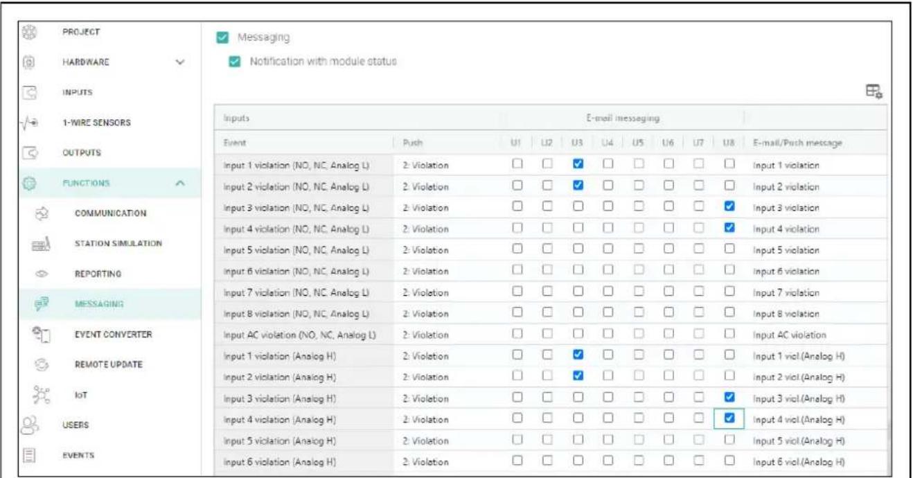
Fig. 27. "Messaging" tab.
6.12 Event converter
The module can notify the users of events received from the control panel. Notifications can be realized via e-mail and push messages. The text of messages to be used for notification must be programmed.
You can indicate 32 events of which the module will notify the users.
Event converter – if this option is enabled, the module can notify the users of the events received from the control panel.
Add event details to E-mail – if this option is enabled, the number of partition where the event occurred and the user or the number of zone that caused the event will be automatically added to the e-mail message sent by the module after receiving the event code. The option only applies to event codes in Contact ID format.

- click to show the table options. The options enable you to hide / show the selected columns in the table and to fit the columns to its content or to the width of the window.
Ident. – identifier that must precede the event code so that the module can send notification of the event. For 4/2 or Contact ID format, you can enter 4 characters (digits or letters from A to F). For SIA format, you can enter 6 characters. If you program no identifier, regardless of what kind of identifier is to precede the event code, receiving it will result in sending the message.
Format – format in which the event code must be received so that the module can send notification of the event. You can select: 1: 4/2, 2: CID or 3: SIA. Click on the field and enter a digit from 1 to 3 or select the code from the list.
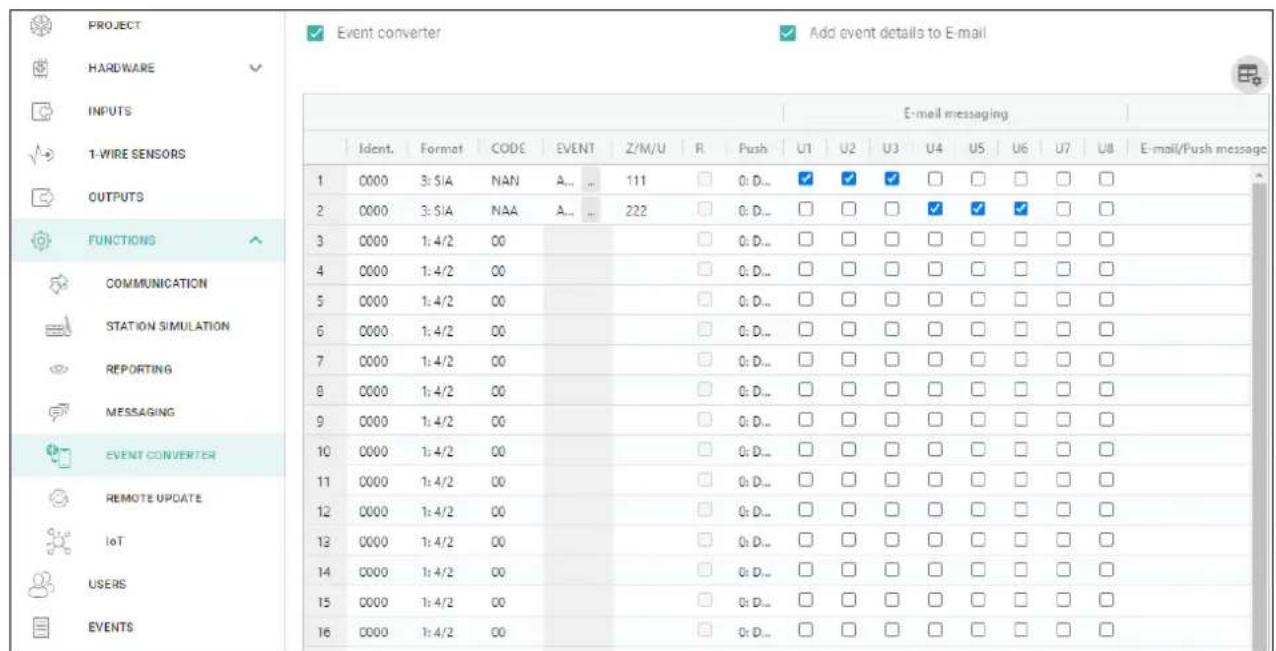
Fig. 28. "Event converter" tab.
CODE – event code, after receiving of which notification of the event will be sent. For 4/2 format, enter 2 characters (digits or letters from A to F). For Contact ID or SIA format, you can use the code editor. To open the code editor window, click in the "Event" field.
EVENT – event description. The field applies to SIA and Contact ID formats. It is autocompleted after entering the code into the "CODE" field.
Z/M/U – number of zone / module / user that must be included in the received code so that the module can send notification of the event. The field applies to SIA and Contact ID formats.
R – the option applies to Contact ID format. If it is enabled, the received event code refers to event restore / arming. If it is disabled, the received event code refers to a new event.
Push – event category. You can assign the event to one of the following categories: 1: Alarm / 2: Violation / 3: Restore, / 4: Output control, / 5: Input bypass / 6: Diagnostics / 7: Other / 8: Push to all. If you assign 0:Disabled to the event, the module will not send push notifications about this event. Click on the field and enter a digit from 0 to 8 or select the category from the list.
U1...U8 – define the events about which a given user will be notified by e-mail (see "Users" p. 40). If the user is to be notified about a given event, check the box in the row containing the code of this event. Click on the column header (e.g. U1) to view the menu that will enable you to check / uncheck all boxes and to invert your selection in the column.
E-mail/Push message – the text of the e-mail / push message which will be sent after receiving the selected event code. The message may be composed of up to 32 characters.
6.13 Remote update
Remote update of the module firmware is made possible by the "UpServ" update server, which is included in the SATEL product portfolio.
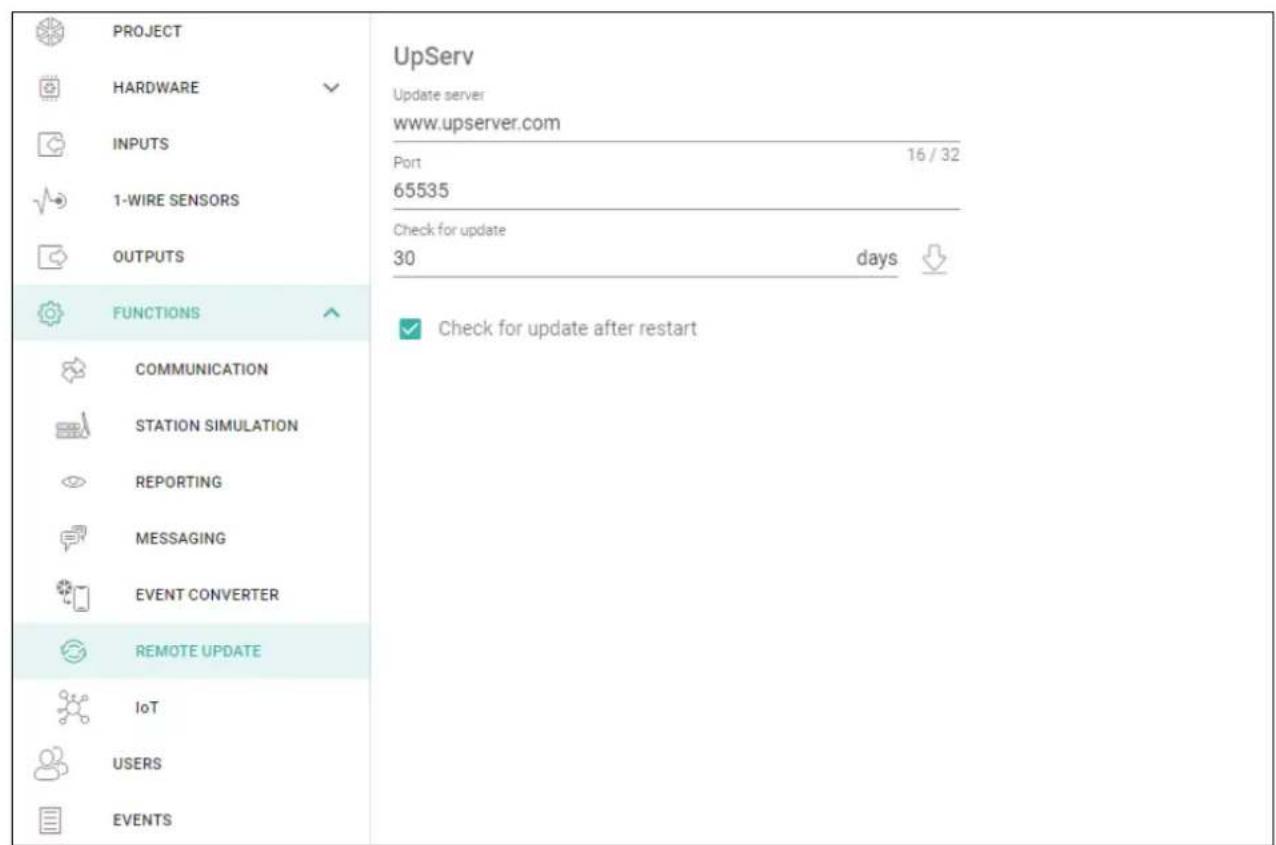
Fig. 29. "Remote update" tab.
UpServ
Update server – address of the "UpServ" update server. You can enter the IP address or domain name.
Port – number of the TCP port used for communication with the "UpServ" update server. You can enter values from 0 to 65535 (0=disabled).
Check for update – define every how many days the module will check for a new firmware version (up to 31 days). If you leave the default 0, checking will be disabled.

- click to start remote firmware update.
Check for update after restart – if this option is enabled, the module will connect to the update server after each restart and check if a new firmware version is available.
6.14 IoT
The module can work as part of the Internet of Things (IoT). This enables the module to be integrated with other systems (including automation or measurement data acquisition) in order to transfer the module registered data to them and receive the control commands for the module from them.
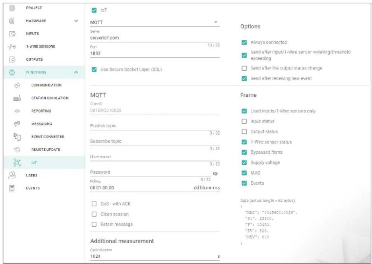
Fig. 30. "IoT" tab.
IoT – if this option is enabled, the module can communicate with the IoT devices.
[Protocol] – protocol used for communication. You can select: MQTT, JSON or JSON/HTTP. Format of data sent by means of each protocol – see "Appendix" p. 44.
Server – address of the server to which the module is connected when working as part of the Internet of Things. You can enter the IP address or domain name.
Port – number of TCP port used for communication with the server. You can enter values from 1 to 65535.
Use Secure Socket Layer (SSL) – if this option is enabled, communication with the server is encrypted. If communication on the server side is not encrypted, the option should be disabled.
MQTT
Define parameters of communication with the server for the "MQTT" communication protocol.
JSON / JSON/HTTP.
Define every how many days, hours, minutes and seconds the module is to send data to the server using the "JSON" communication protocol.
HTTP header
Define the information that will be contained in the header of the frame sent by the module using the "JSON/HTTP" communication protocol. You can enter a text of your choice. The text displayed in the "HTTP header" field is only an example and can be freely modified. When defining the header you can use variables that the module will replace in the frame header with the following information:
%H% – address of the server with which communication is taking place,
%P% – number of TCP port used for communication with the server,
%V% – version number of module firmware.
See example of a frame with a header in "JSON/HTTP protocol" p. 45.
Additional measurement
The module can cyclically take an additional measurement using sensors connected to the analog inputs and digital 1-Wire sensors. You can define the length of the measurement cycle during which the data will be registered. At the end of the cycle the module will send the measurement results to the server (for the format of the data to be sent, see “Format of frames with additional measurement results” p. 45). You can program up to 3600 seconds. If you leave 0 in the “Cycle duration” field, the additional measurement will not be taken.
Options
Always connected – if this option is enabled, the module, after sending the data, will maintain connection to the server until the next transmission. If this option is disabled, the module, after sending the data, will wait a few seconds for a response from the server and terminate the connection. Connection to the server will then be established during the next transmission. The time between subsequent transmissions is defined in the “Polling” field.
Send after input/1-Wire sensor violating/threshold exceeding – if this option is enabled, violation / threshold exceeding in case of input / 1-Wire sensor will start data transmission.
Send after the output status change – if this option is enabled, change of the output status will start data transmission.
Send after receiving new event – if this option is enabled, data transmission will be started each time an event occurs in the module or each time the module receives an event from the control panel.

Each data transmission will reset the countdown before sending the next cyclic data transmission (“Polling” field).
Frame
Define the type of data contained in the frame sent by the module (for a detailed description of the data to be sent, see “Format of frames sent by the module” p. 44).
Used inputs/1-Wire sensors only – if this option is enabled, the frame will only contain data from the inputs / 1-Wire sensors being in use.
Input status – if this option is enabled, the frame will contain information about the status of inputs.
Output status – if this option is enabled, the frame will contain information about the status of outputs.
1-Wire sensor status – if this option is enabled, the frame will contain information about temperature from 1-Wire sensors.
Bypassed items – if this option is enabled, the frame will contain information about bypassed inputs / 1-Wire sensors.
Supply voltage - if this option is enabled, the frame will contain information about the module supply voltage.
MAC – if this option is enabled, the frame will contain the module hardware address.
Events – if this option is enabled, the frame will contain the index of the event last saved to module memory (EV) and the maximum event index (MEV).

Enabling / disabling the option will update the data displayed in the "Data" field.
Data (actual length = [number] bytes) – information about the type of data that will be contained in the frame sent by the module (see “Format of frames sent by the module” p. 44). Information about the current size of the frame is displayed above the field.
6.15 Users
You can enter data of 8 users.
| PROJECT | |||||
| HARDWARE | ID | User | Password | ||
| INPUTS | 1 | Kamil S | ********** | staszewski.k@gmail.com | |
| 1-WIRE SENSORS | 2 | User 2 | ********** | 1123asafsdf@onet.pl | |
| OUTPUTS | 3 | Jacek P | ********** | j.pasincki@catel.pl | |
| FUNCTIONS | 4 | User 4 | ********** | ||
| USERS | 5 | User 5 | ********** | ||
| EVENTS | 6 | User 6 | ********** | ||
| 7 | Piotr N | ********** | nowak.p@wp.pl | ||
| 8 | Janusz K | ********** | kowalskijanusz@gmail.com | ||
Fig. 31. "Users" tab.

- click to show the table options. The options enable you to hide / show the selected columns in the table and to fit the columns to its content or to the width of the window.
ID – individual number of the user.
User – individual name of the user (up to 16 characters).
Password – password to establish connection between the GX Control and the module (see p. 41). You can enter from 4 to 8 digits.

The password must be unique for each user.
E-mail – e-mail address of the user to which notifications will be sent by the module (see "Messaging" p. 34).
6.16 Events
Up to 500 events generated by the module or received from the control panel can be recorded in the module non-volatile memory.
The search field is displayed above the table. If you want to find an event:
-
Click on the search field and enter a string of characters contained in the event details (e.g. the event description or date of its occurrence).
-
Click Events that meet the search criteria will be displayed.

If you want to go back to all events, click in the search field (this will clear all the characters entered in the field).
☐ – click to clear the module event log.
C – click to refresh the list of events.
- click to show the table options. The options enable you to hide / show the selected columns in the table and to fit the columns to its content or to the width of the window.
| PROJECT | ||||||||
| HARDWARE✓ | No. ↓ | Date | Time | Description | Source | Station 1 | Station 2 | |
| INPUTS | 326 | 2000-01-01 | 01:00:13 | Output 2 ON | ||||
| T-WIRE SENSORS | 325 | 2000-01-01 | 01:00:13 | Trouble: ETH Srv2 ST1 | ||||
| OUTPUTS | 324 | 2000-01-01 | 01:00:12 | Output 2 OFF | ||||
| FUNCTIONS✓ | 323 | 2000-01-01 | 01:00:12 | Trouble: ETH Srv1 ST1 | ||||
| USERS✓ | 322 | 2000-01-01 | 01:00:06 | Input 2 bypassed | ||||
| 321 | 2000-01-01 | 01:00:06 | Output 1 ON | |||||
| 320 | 2000-01-01 | 01:00:06 | Input AC violation (NO, NC, Anal... | - | ||||
| 319 | 2000-01-01 | 01:00:05 | Output 3 ON | |||||
| 318 | 2000-01-01 | 01:00:05 | Output 2 ON | |||||
| 317 | 2000-01-01 | 01:00:05 | Module restart | |||||
| 316 | 2021-10-21 | 10:13:29 | Test transmission | - | ||||
| 315 | 2021-10-21 | 10:12:08 | GX Soft disconnected | |||||
| 314 | 2021-10-21 | 10:05:44 | Input 3 restore (NO, NC, Analog ... | |||||
| 313 | 2021-10-21 | 10:05:39 | Input 3 violation (NO, NC, Analo... | |||||
Fig. 32. "Events" tab.
Events are shown sorted by time in descending order from the latest (top) to the oldest (bottom). Individual columns present the following information:
No. – consecutive event number.
Date – date the event occurred in the module / event from the control panel was saved to the module memory (see "Events buffering" p. 29).
Time – hour the event occurred in the module / event from the control panel was saved to the module memory (see "Events buffering" p. 29).
Description – event description (for events in Contact ID or SIA format).
Source – name of source that generated the event.
Station 1 / Station 2 – reporting status:
[blank field] – event is not reported,
. – event waiting to be sent to the monitoring station,
+ - test transmission sent to the monitoring station,
- - sending test transmission has failed,
* – sending event cancelled (e.g. reporting has been disabled),
[monitoring station server name] – event sent successfully to the given monitoring station server.
You can sort the data in the table. If you click on the selected column header (e.g. "Date"), the table will be sorted by the data in that column. The symbol indicating the current sorting method ( – ascending, – descending) will be displayed in the column header.
7. GX Control application
The GX Control is a mobile application that allows you to remotely operate the ETHM-A module i.e.:
- check the status of inputs, 1-Wire sensors and outputs,
- bypass / unbypass the inputs and 1-Wire sensors,
• control outputs,
- view troubles,
• view the event log.
Additionally, the application can provide information on the events by using push notifications.
Communication between the application and the module is encrypted.

Password required to establish connection between the GX Control and the ETHM-A module must be programmed in the user list (see "Users" p. 40).
You can download the application from the internet stores: "Google play" (Android system devices) or "App Store" (iOS system devices).
When the application is run for the first time, you will be asked if you want to password protect the access to the application. After you define the application access rules, a tutorial will be displayed to teach you how to configure settings for communication with the module. For a new module, the settings can be configured automatically, or you can enter them manually. Fig. 33 shows the GX Control screen that allows you to select how the communication settings are to be configured.
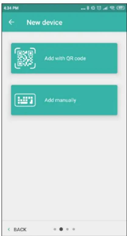
Fig. 33. GX Control application (Android system): select how to configure the settings for a new module.
Add with QR code
Tap the button to start the QR code scanner and enable communication settings to be read from the QR code (see p. 18).
If the communication settings are configured on one mobile device, they can be easily copied to another mobile device. Just display the QR code on the device in which the settings for communication with the given module are already configured, and read the code on another device.
Add manually
Tap the button to display a window (see Fig. 34), in which you must:
- enter the module name (to enable identification of the module when using the application),
- enter the module MAC address (the module hardware address),
- enter the module ID number (the individual identification number for the purpose of communication via the SATEL server – see “Project” tab p. 18),
- enter the user password (the password programmed in the module – see "Users" p. 40),
- select the icon (to facilitate identification of the module when using the application).
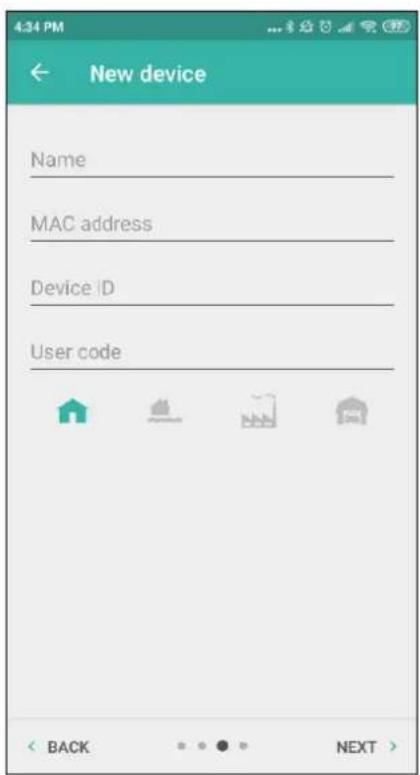
Fig. 34. GX Control application (Android system): manual configuration of new module settings.
8. Module firmware update

When the firmware update is running, the module does not execute its normal functions.
Save the module settings before you run the firmware update.
8.1 Local update
- Download the ETHM-A module firmware update from www.satel.eu.
- Connect the module USB port with the computer USB port.
- Run the update program.
- When you will be asked if you want to continue the firmware update, click "Yes". The module firmware will be updated.
4. Click

8.2 Remote update
- Program the parameters in the module to enable the remote update of the module firmware (see "Remote update" p. 36).
- Initiate the update from the GX Soft program (see p. 11).
9. Restoring the factory settings
- Click on the "Project" tab in the GX Soft program.
- Click on the "Factory settings" button. You will be asked if you want to restore the factory settings in the module.
- Click on "Yes".
10. Specifications
Number of inputs....8
Number of outputs (OC type) 4
Supply voltage 12 VDC ±15%
Standby current consumption ....60 mA
Maximum current consumption....80 mA
Maximum permissible voltage on AC input 25 VAC
Outputs (OC type)....50 mA / 12 VDC
Environmental class according to EN 50130-5 ......II
Operating temperature range....-10...+55°C
Maximum humidity 93±3%
Enclosure dimensions 83 x 60 x 26 mm
Weight....76 g
11. Appendix
11.1 Data format for MQTT, JSON and JSON/HTTP protocol
11.1.1 Format of frames sent by the module
Format of the main frame
The module uses the MQTT, JSON and JSON/HTTP protocols to cyclically send to the server a frame with data registered by the module. Define the data to be sent in the frame (see "Frame" p. 39). For a frame sent using the JSON/HTTP protocol, you can also define the header (see "HTTP header" p. 39). Examples of frames sent using different protocols are shown below.
MQTT and JSON protocol
{"MAC":"868325024202972", "I1":11841, "BI2":1, "I3":0, "I4":0, "I5":0, "I6":0, "I7":0, "I8":0, "AC":0, "S1":0, "BS2":1, "S3":0, "S4":0, "S5":0, "S6":0, "S7":0, "S8":0, "O1":1, "O2":0, "O3":1, "O4":0, "P":13692, "EV":44, "MEV":619}}
MAC – module hardware address.
I1...I8 - input status (NO [0 = not violated, 1 = violated], NC [1 = not violated, 0 = violated] / value on the analog input (scaled and multiplied by 1000).
BI1...8:1 – input bypassed.
AC – AC input status (0 = not violated [AC voltage present], 1 = violated [no AC voltage]).
BAC:1 - AC input bypassed.
S1...S8 – value from the digital 1-Wire temperature sensor (multiplied by 1000).
BS1...8:1 - 1-Wire temperature sensor bypassed.
01...04 – output status (normal polarity: 0=OFF, 1=ON / reverse polarity: 1=OFF, 0=ON).
P – value of the module supply voltage (multiplied by 1000).
EV – index of the event last saved to module memory.
MEV – maximum index for events saved to module memory (circular buffer).
JSON/HTTP protocol
POST http://192.168.7.230:502/write HTTP/1.1
User-Agent: ETHM-A 1.00.000
Content-Type: application/json
{"MAC":"868325024202972", "I1":11841, "BI2":1, "I3":0, "I4":0, "I5":0, "I6":0, "I7":0, "I8":0, "AC":0, "S1":0, "BS2":1, "S3":0, "S4":0, "S5":0, "S6":0, "S7":0, "S8":0, "O1":1, "O2":0, "O3":1, "O4":0, "RSSI":64, "P":13692, "SP":"XY [2G]", "EV":44, "MEV":619}
192.168.7.230 - address of the server with which communication is taking place (%H%).
502 – number of TCP port used for communication with the server (%P%),
1.00.000 – version number of module firmware (%V%).
For description of other data, see "MQTT and JSON protocol".
Format of frames with additional measurement results
The module uses the MQTT, JSON and JSON/HTTP protocols to cyclically send to the server two additional frames with data registered by analog sensors (first frame) and digital 1-Wire temperature sensors (second frame). The frames are sent by the module when the additional measurement function is enabled in the module (see “Additional measurement” p. 39). See the example below (MQTT or JSON protocol frames):
{"MAC":"868325024202972", "I1_avg":10, "I1_min":0, "I1_max":51, "I2_avg":13585, "I2_min":9818, "I2_max":13914, "I3_avg":10, "I3_min":0, "I3_max":63, "I4_avg":6, "I4_min":0, "I4_max":55, "I5_avg":5, "I5_min":0, "I5_max":52, "I6_avg":5, "I6_min":0, "I6_max":68, "I7_avg":4, "I7_min":0, "I7_max":64, "I8_avg":5, "I8_min":0, "I8_max":47}
{"MAC":"868325024202972", "S1_avg":27250, "S1_min":27250, "S1_max":27250, "S2_avg":25000, "S2_min":25000, "S2_max":25000, "S3_avg":26250, "S3_min":26250, "S3_max":26250, "S4_avg":26000, "S4_min":26000, "S4_max":26000, "S5_avg":25250, "S5_min":25250, "S5_max":25250, "S6_avg":25970, "S6_min":26000, "S6_max":26000, "S7_avg":26500, "S7_min":26500, "S7_max":26500, "S8_avg":26250, "S8_min":26250, "S8_max":26250}
MAC – module hardware address.
I1_avg...l8_avg – average value from measurements registered on the input during the measurement cycle (scaled and multiplied by 1000).
I1_min...l8_min – minimum value registered on the input during the measurement cycle (scaled and multiplied by 1000).
I1_max...l8_max – maximum value registered on the input during the measurement cycle (scaled and multiplied by 1000).
S1_avg...S8_avg – average temperature value from measurements registered by the digital 1-Wire sensor during the measurement cycle (multiplied by 1000).
S1_min...S8_min – minimum temperature registered by the digital 1-Wire sensor during the measurement cycle (multiplied by 1000).
S1_max...S8_max – maximum temperature registered by the digital 1-Wire sensor during the measurement cycle (multiplied by 1000).
11.1.2 Format of the module control frame
You can use the JSON and MQTT protocol to send to the module a frame with control command:
"BIX":1 / "BIX":0 – bypass / unbypass input, where: X = input number from 1 to 8.
"BAC":1 / "BAC":0 – bypass / unbypass AC input.
"BSX":1 / "BSX":0 – bypass / unbypass 1-Wire temperature sensor, where: X = sensor number from 1 to 8.
"OX":1 / "OX":0 – activate / deactivate output, where: X = output number from 1 to 4.
"MOX":1 / "MOX":0 – activate / deactivate output and save its status, where: X = output number from 1 to 4 (after module restart or power supply failure, the output will be switched to the status saved).
"TOX":1 – activate output for the time preset in the module (see "Operating time" p. 26), where: X = output number from 1 to 4.
A frame sent to the module may contain several control commands arranged in any order; see the example below:
{"MO3":0, "O2":1, "TO5":1, "BI2":1, "BS1":0, "BAC":1}
where:
"MO3":0 – deactivate output 3 and save its status,
"O2":1 – activate output 2,
"TO4":1 – activate output 4 for the time preset in the module,
"BI2":1 – bypass input 2,
"BS1":0 - unbypass sensor 1 on 1-Wire bus,
"BAC":1 - bypass AC input.
11.1.3 Format of the event log reading frame
You can use the JSON and MQTT protocols to send to the module a frame with control command that will start the reading of events saved to module memory. See the example below:
{"GEV": {"EV":27, "CNT":10, "DIR":"-"}}
where:
GEV – control command which, if sent to the module, will start the reading of events in accordance with the following parameters:
EV – index of the event from which to start the reading,
CNT – number of events which are to be read (number of events read may be limited by the amount of free memory available in the module buffer),
DIR – direction of reading:
-
- if you want events that occurred prior to the starting point to be read,
-
- if you want events that occurred later than the starting point to be read.
In response to the command the module will send a frame containing the list of events with the following information displayed for each of the events:
EV – event index,
ET – event type (linked to DATA field),
TS – Unix timestamp (GMT),
DATA – event description.