E-ZTR 2692062 - Lawn mower Victa - Free user manual and instructions
Find the device manual for free E-ZTR 2692062 Victa in PDF.

| Product Type | Zero-Turn Lawn Mower |
| Brand | Victa |
| Model | E-ZTR 2692062 |
| Engine Type | Gasoline, 4-stroke |
| Engine Power | Approx. 24 HP |
| Cutting Deck Width | 54 inches |
| Cutting Height Range | 1.5 - 4.5 inches |
| Cutting Height Adjustment | Manual lever, 12 positions |
| Drive System | Hydrostatic, dual lever control |
| Turning Radius | Zero-turn capability |
| Maximum Speed | Forward: 6 mph; Reverse: 3 mph |
| Fuel Tank Capacity | 3 gallons |
| Weight | Approx. 550 lbs (shipping weight) |
| Overall Dimensions (L x W x H) | 72 x 54 x 45 inches |
| Blade Engagement | Electric clutch with switch |
| Mower Deck Material | Stamped steel |
| Safety Features | Operator presence control, seat switch, blade brake |
| Maintenance | Oil change every 50 hours; air filter cleaning; blade sharpening |
| Warranty | 2-year limited residential; 90-day commercial |
| Assembly Required | Yes (minor assembly – handle, seat, etc.) |
| Replacement Parts | Spindle assemblies, belts, blades, filters available |
Frequently Asked Questions - E-ZTR 2692062 Victa
User questions about E-ZTR 2692062 Victa
0 question about this device. Answer the ones you know or ask your own.
Ask a new question about this device
Download the instructions for your Lawn mower in PDF format for free! Find your manual E-ZTR 2692062 - Victa and take your electronic device back in hand. On this page are published all the documents necessary for the use of your device. E-ZTR 2692062 by Victa.
USER MANUAL E-ZTR 2692062 Victa
natural_image
Technical line drawing of a small wheeled vehicle with wheels, motors, and structural components (no text or symbols)INTRODUCTION
Dear Customer,
Thank you for choosing a Victa ride-on lawnmower.
This manual describes and illustrates the safety, assembly, operation and maintenance instructions to be followed to ensure the safe and efficient operation of the machine.
Please remember that this manual is an integral part of the machine; look after it and keep it handy for future reference. In the event the machine is sold, this operator manual must be provided to the new owner.
If your ride-on lawnmower needs assistance or repair, please contact your local Victa authorised service centre.
Visit Victa.com.au to find your closest Victa authorised service centre.
IMPORTANT
The ride-on lawnmower must always be used with utmost caution. To ensure safety precautions and operating instructions are readily on hand, labels with pictographs have been affixed to your ride-on lawnmower. As these labels are applicable to safety standards, they are considered an integral part of the machine. Therefore the user is responsible for replacing them in the event they become detached or illegible.
For any replacement, contact your Victa authorised service centre.
TABLE OF CONTENTS

Definitions of Symbols 3

Safety Precautions 5
General Information
Preparation Before Operating
Operation
Children Specific
Slope Specific
Transport
Towing
Service
Save These Instructions

Parts & Controls 9
Machine Parts
Control Panel

Machine Assembly 17
Unpacking
Installing Side Discharge Chute
Installing Tow Hitch
Installing Seat
Attaching Mulching Cover
Fitting Steering Levers

Operating Instructions 22
| Before Operating | ||
| Cutting Deck Height Adjustment | ||
| Seat Adjustment | ||
| Setting the Parking Brake | ||
| Charging | ||
| Intended Use | ||
| Before Starting the Mower | ||
| Starting the Mower | ||
| Stopping the Mower | ||
| Operating the Mower | ||
| Mowing Tips | ||
| Operating on a Slope | ||
 | Maintenance 32 | |
| Recommended Maintenance Schedules | ||
| General Maintenance | ||
| Cleaning the Mower | ||
| Adjusting the Anti-Scalp Wheels | ||
| Adjusting the Blades (Front to Rear) | ||
| Removing the Mower Deck | ||
| Removing the Blades | ||
| Installing the Blades | ||
| Checking the Tyre Pressure | ||
| Replacing the Wheels | ||
| Calibrating the Drive Tracking | ||
| Transporting the Mower | ||
| Storing the Mower | ||
 | Troubleshooting 46 | |
 | Technical Specification 53 | |
| Notes 54 |

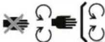
DEFINITIONS OF SYMBOLS
The purpose of safety symbols is to attract your attention to possible dangers. The safety symbols and the explanations with them deserve your careful attention and understanding. The symbol warnings do not, by themselves, eliminate any danger. The instructions and warnings they give are no substitutes for proper accident prevention measures.

WARNING: Be sure to read and understand all safety instructions in this Operator Manual, including all safety alert symbols such as "DANGER," "WARNING," and "CAUTION" before using this machine. Failure to follow all instructions listed below may result in electric shock, fire, and/or serious personal injury.
This page depicts and describes safety symbols that may appear on this product. Read, understand, and follow all instructions on the machine before attempting to assemble and operate.
| SYMBOL DEFINITIONS | |
 | Warning: Stay alert. Indicates a potential personal injury. |
 | Read & Understand Operator Manual. To reduce the risk of injury, user must read and understand operator manual before using this product. |
 | Eye Protection: Always wear eye protection with side shields marked to comply with ANSI Z87.1 when operating this product. |
 | Maintain Safety Devices: Do not open or remove safety shields while the product is running. |
 | WARNING — Keep Hands and Feet Away: To reduce the risk of injury, keep hands and feet away from rotating parts. Do not operate unless discharge cover or grass bag is in its proper place. If damaged, replace immediately. |
 | DANGER — Keep Bystanders Away: Do not mow when children or others are around. |
 | Never Carry Children: Never carry children or anyone, even when the blades are off. |
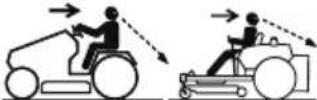 | Look Behind While Backing. Always look down and behind you before and when manoeuvring in reverse or turning around. Make sure children, bystanders, and pets are clear of the area. |
 | DANGER — Steep Slope Hazard: Use extra caution on slopes. Do not mow slopes greater than 15 degrees. Do not use on slopes near open water. |
 | WARNING — Do not expose battery, battery compartment, or electronic components to rain, water or liquids. Do not charge battery or expose mower to rain or damp locations. |
| SYMBOL DEFINITIONS | ||
 | DANGER — Thrown Objects: Remove objects that can be thrown by the blade in any direction. Wear safety glasses. | |
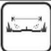
 |   | DANGER — Retaining Walls, Drop-Offs, or Water: Stay at least two mowing widths (2m) away from any ditches, drop-offs, or water to avoid accidentally going over the edge or into the water. |
 51.2V --- 100Ah 51.2V --- 100Ah | 51.2V-100Ah Li-Ion Battery | |
 42" 42" | 42" Cutting width | |
 255 kg 255 kg | 255 kg net weight | |
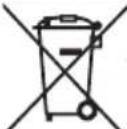 | WEEE symbol. Waste electrical products should not be disposed of with household waste. Please recycle where facilities exist. Check with your Local Authority or local store for recycling advice. | |
 Li Ion Li Ion | Batteries contain Li-Ion and should not be disposed with general household waste. Contact your Local Authority for disposal advice. | |
 | RCM E915 | |
 | Guaranteed sound power level value is 100dB | |
 | Beware of electric shock when charging. | |
General Information

DANGER: This machine is capable of amputating hands and feet and throwing objects. Failure to observe the following safety instructions could result in serious injury or death.
- Read, understand, and follow instructions and warnings in this manual and on the machine and attachments.
- Only allow operators, who are responsible, trained, familiar with the instructions, and physically capable to operate the machine.
- Do not carry passengers and keep bystanders away.
- Do not operate the machine while under the influence of alcohol or drugs.
- Follow the manufacturer's recommendation for wheel weights or counterweights.
Preparation Before Operating
- Clear the operating area of any objects which could be thrown by or interfere with operation of the machine.
- Keep the area of operation clear of all bystanders, particularly small children. Stop the machine and attachment(s) if anyone enters the area.
- Do not operate the machine without the entire grass catcher, discharge chute, or other safety devices in place and functioning properly. Check frequently for signs of wear or deterioration and replace as needed.
- Wear appropriate personal protective equipment such as safety glasses, hearing protection, and footwear.
Operation
- Use only with approved Victa charger.
- Only operate the machine in daylight or good artificial light.
- Avoid holes, ruts, bumps, rocks, or other hidden hazards. Uneven terrain could overturn the machine, or cause operator to lose their balance or footing.
- Do not put hands or feet near rotating parts or under the machine. Keep clear of the discharge opening at all times.
- Do not direct discharge material toward anyone. Avoid discharging material against a wall or obstruction. Material may ricochet back toward the operator. Stop the blade(s) when crossing gravel surfaces.
- Do not leave a running machine unattended. Always park on level ground, disengage the attachment, set parking brake, and stop the motor.
- Do not mow in reverse unless absolutely necessary. Always look down and behind before and while backing.
- Avoid mowing wet grass. Poor footing could cause a slip and fall accident.
- If situations occur that are not covered in this manual, use care and good judgment.
Children Specific
- Tragic accidents can occur if the operator is not alert to the presence of children. Children are often attracted to the machine and the mowing activity. Never assume that children will remain where you last saw them.
- Keep children out of the operating area and under the watchful care of a responsible adult other than the operator.
- Do not carry children, even with the blade(s) shut off. Children could fall off and be seriously injured or interfere with safe machine operation. Children who have been given rides in the past could suddenly appear in the mowing area for another ride and be run over or backed over by the machine.
Slope Specific

WARNING: Slopes are a major factor related to accidents. Operation on slopes requires extra caution.
- Travel in the manufacturer recommended direction on slopes. Use caution while operating near drop-offs.
- Do not operate machine under any condition where traction, steering, or stability is in question.
- Tyres could slide even if the wheels are stopped.
• Always keep the machine in gear when going down slopes. Do not coast downhill. - Avoid starting and stopping on slopes. Avoid making sudden changes in speed or direction.
• Make turns slowly and gradually. - Use extra care while operating machine with a grass catcher or other attachment(s). They can affect the stability of the machine.
Refer to "Operating on a Slope" on Page 32 of this manual for complete instructions.
Transport
- The machine is heavy and can cause serious crushing injuries. Be extra cautious when it is loaded on or unloaded from a vehicle or trailer.
- Use full width ramps for loading machine into a trailer or vehicle.
- Use an approved trailer to transport the machine. Operate the parking brake by securing the steering levers in the open position and set the parking brake pedal to the braking position.
- Fasten the machine down with approved devices such as bands, chains or straps.
- Both front and rear tie down straps must be used and directed down and out from the machine.

WARNING: Use extreme caution when loading the machine into a vehicle or trailer using ramps. There is the possibility of serious injury or death if the machine falls off the ramps.

WARNING: The parking brake is not sufficient to lock the machine in place during transport. Ensure that the machine is well fastened to the transport vehicle. Always reverse the machine onto the transport vehicle to avoid tipping it over.
- Do not operate this machine on public roadways.
- Check and abide by local traffic regulations before transporting the machine on roads.
- Do not tow this machine, it may cause damage to the drive system.
- Load the unit onto vehicle or trailer by driving up ramps of suitable strength using a slow speed.
- Do not lift! The machine is not intended to be lifted by hand.
- When loading or unloading this machine, do not use more than the maximum recommended operation angle of 15 degrees.
For complete transporting instructions refer to "Transport the Mower" on page 45 of this manual.
Towing
- Do not tow a cart that exceeds 113 kg total rolling weight and never exceed 22 kg tongue weight. The weight of the cart and other specifications are included in the operator's manual supplied with your cart.
- Attach towed cart only to the hitch. Risk of personal injury or property damage.
- Never allow children or other persons in or on towed cart. Risk of personal injury.
- Do not tow on inclines more than 5 degrees / 9%. The weight of the towed cart may cause loss of traction, loss of control and the ability to stop when towing on inclined surface.
- Always use extra caution when towing with your zero turn mower. Make wide turns to avoid jackknifing. Use care when reversing.
- Drive at slow speed and allow extra distance to stop.
- Do not tow near ditches, canals, and other hazards. There is a risk of loss of traction or control.
- Follow all the warnings and instructions provided by the cart manufacturer. Failure to follow all instructions may result in personal injury or property damage.
- Follow the manufacturer's recommendation for weight limits for towed equipment and towing on slopes.
Service

WARNING: The grass bag components, side discharge cover and mulching insert are subject to wear and damage. This could expose moving parts or allow objects to be thrown and could increase the risk of injury. For safety protection, frequently check all components and replace damaged components immediately with identical replacement parts, listed in this manual.
- Keep machine in good working order. Replace worn or damaged parts. Check the function of the drive motors and brakes periodically.
- Use caution when servicing blades. Wrap the blade(s) or wear gloves. Replace damaged blades. Do not repair or alter blade(s).
• Always stop the motor and remove safety key before servicing, cleaning, or removing material from the ride-on mower.
• After striking a foreign object, stop the motor and remove safety key, allow the blade to stop rotating, and thoroughly inspect the ride-on mower for any damage. Rectify the damage before operating the ride-on mower. - Have your ride-on lawn mower serviced by a qualified repair person using only identical replacement parts. This will ensure that the safety of the ride-on lawn mower is maintained.
- Follow instructions for changing accessories.
- Keep the ride-on mower free from accumulation of grease, dirt, and other possibly combustible materials.
- Keep all nuts, bolts, and screws tight to be sure the ride-on mower is in safe working condition.
- Never remove or tamper with safety devices. Regularly check their proper operation. Never do anything to interfere with the intended function of a safety device or to reduce the protection provided by the safety device.
- Maintain or replace safety and instruction labels, as necessary.
- Recharge only with the charger specified by the manufacturer. A charger that is suitable for one type of battery pack may create a risk of fire when used with another battery pack.
- Do not charge ride-on mower in rain, or in wet locations.
- Do not use battery operated ride-on mower in rain.
- Do not wash the ride-on mower with a hose; avoid getting water in the motor and electrical connections.
- Store idle ride-on mower indoors – When not in use, ride-on mower should be stored in an indoor dry and secure place – out of reach of children.
Save These Instructions
- Refer to them frequently and use them to instruct others who may use this product. If you lend this product to someone else, also lend these instructions to them to prevent misuse of the product and possibly injury.
CAUTION - Risk of overturning on steep gradients.
Do not use the machine on lawns with gradients of more than 25% (14 degrees).
Do not use the machine on lawns with side gradients above 15% (8 degrees).
Machine Parts

text_image
Technical diagram of a motor assembly with numbered parts for identification and assembly reference.1) Machine Body
2) Seat
3) Steering Levers
4) Side Discharge Chute Kit
5) Mulching Cover Kit
6) Tow Hitch Bracket
7) Socket Head Screws (x6)
8) Hex Bolts (x6)
9) Nut (x2)
10) Hex Bolts with Washer (x2)
11) Safety Key
12) Socket Wrench 13mm
13) Allen Key 6mm
14) Wash Port Quick Coupler
15) Combination Wrench 13mm x 2
MACHINE PARTS AND CONTROLS
text_image
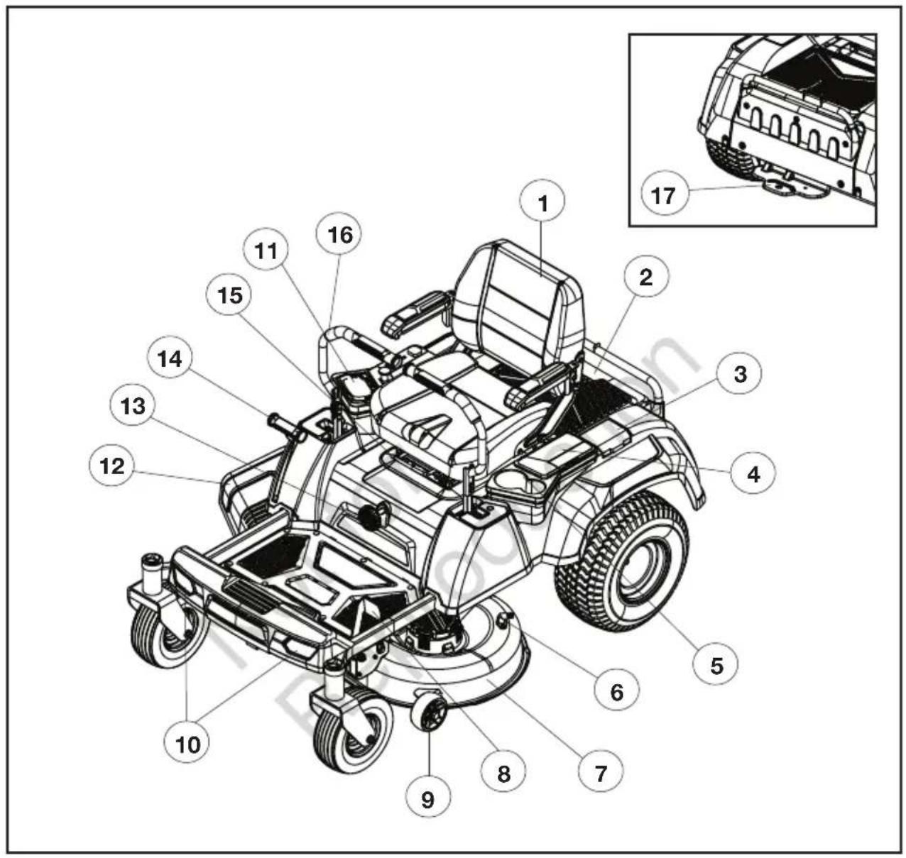
Technical diagram of a golf cart with numbered parts for identification and assembly reference.1) Seat
2) Battery Compartment
3) Charging Port
4) Storage Box
5) Cup Holders
6) Wash Port
7) Cutting Deck
8) Parking Brake Pedal
9) Anti-Scalp Wheel
10) LED Headlights
11) Control Panel
12) Side Discharge Chute
13) Seat Suspension Adjustment Knob
14) Deck Height Adjustment Lever
15) Seat Forward-Back Adjustment Lever
16) Steering Lever
17) Tow Hitch
PARTS & CONTROLS
Charging Port
Open the port to connect the battery charger.
Storage Boxes
The left-hand side storage box is designed for storage of small belongings.
The right-hand side storage box is designed for convenient storage of a mobile phone.
Wash Port
Use the wash port to clean under the cutting deck. Refer to "Cleaning the Mower" in the "MAINTENANCE" section of this manual.
Parking Brake Pedal
Press pedal to engage or disengage the parking brake.
Anti-Scalp Wheel
Helps to prevent the deck from contacting the ground and scalping the lawn when passing over a high spot.
LED Headlights
Provides light for mowing in low light conditions and to allow the mower to be seen.
Side Discharge Chute
Allows grass clippings to be discharged from the cutting deck. The side discharge chute is not installed when the mower is shipped. This must be installed before operation. See "Installing Side Discharge Chute" in the "MACHINE ASSEMBLY" section.
Seat Suspension Adjustment Knob
Use the seat suspension adjustment knob to adjust the comfort depending on the operator's weight and the bumpiness of the yard.
Deck Height Adjustment Lever
The deck height adjustment lever raises and lowers the cutting height.
Seat Forward-Back Adjustment Lever
Use the seat forward-back adjustment lever to move the seat back and forth to the desired position.
Steering Levers
The left and right steering levers control the mower's speed, direction, and stopping (neutral position).
natural_image
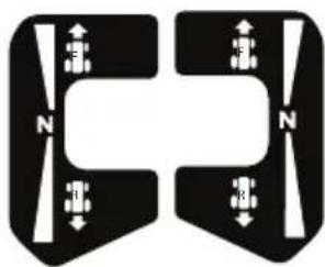
Pure diagram of symmetrical mechanical or electrical components with no text, numbers, or symbolsTow Hitch
For towing carts or other wheeled attachments. Refer to "Towing" section in the "SAFETY PRECAUTIONS" section of this manual.
Control Panel
text_image
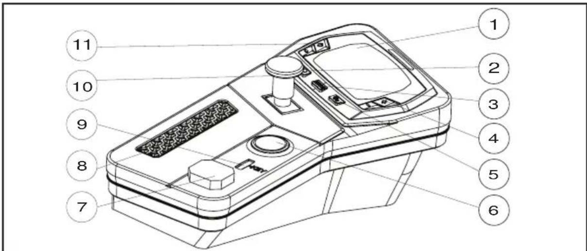
Technical diagram of a device with numbered parts for identification1) LCD Screen 7) USB Port
2) LED Headlight Switch 8) Media Device Storage Box
3) Driving Mode Button 9) Safety Key Slot
4) Blade Speed Adjustment Button 10) PTO Switch
5) Drive Tracking Calibration Button 11) Driving Speed Adjustment Button
6) Start/Stop Button

WARNING: The safe use of this product requires an understanding of the machine, this operator manual, as well as knowledge of the work you are attempting.
Before using this product, familiarise yourself with all operating features and safety rules.
LED Headlight Switch
Controls the headlights.
Driving Mode Button
Driving Mode button makes changes to the input sensitivity of the steering levers. Select CONTROL or STANDARD driving modes by sequentially pressing the driving mode button. The default is STANDARD.
- CONTROL: Provides lower acceleration, less sensitive handling, and mild turning speed to protect the grass.
Recommended for new operators.
• STANDARD: Allows more precise and quick steering response.
Blade Speed Adjustment Button
Allows the user to customise the blade speed, depending on grass conditions. The user can adjust the blade speed during grass cutting. Mowing time will be increased when mowing at lower blade speeds.
- Press “+” to increase the blade speed and press “-” to decrease the blade speed.
Drive Tracking Calibration Button
Refer to "Calibrating the Drive Tracking" in the "MAINTENANCE" section of this manual.
Start/Stop Button
- Press the start/stop button briefly to display the "Standby" screen to display the battery charge level.
- With the safety key is inserted, press and hold the start/stop button for 1 to 2 seconds to display the "On mode" screen and start the mower.
PARTS & CONTROLS
- Press the start/stop button for 1 to 2 seconds to turn the LCD screen off.
- The LCD screen will display battery charge level when pressed briefly.

WARNING: The operator should be familiar and experienced with zero turn mower handling and operations.
USB Port
The USB port provides charging power of 5 V DC at up to a combined draw of 2 A for your device. Consult the owner's manual for your device for specific charging requirements.
NOTICE:
- Attempting to charge devices whose combined draws exceed 2 A could damage the USB port and/or the mower. Always close the storage box cover when not in use to prevent debris from becoming trapped in the USB port.
- The USB port is powered only when the mower is not in charging mode.
Safety Key Slot
The safety key must be inserted before the start/stop button is pressed to start the mower.
PTO Switch
Lift to engage the blades.

NOTICE:
It is recommend to engage the blade motors before cutting heavy grass. If the cutting blade stops while cutting, raise the cutting deck height to the highest position before re-engaging the blade motors by resetting the PTO switch.
Driving Speed Adjustment Button
Allows the operator to select a comfortable driving speed.
- Press “ ” to increase the top driving speed of the mower or press “ ” to reduce the top driving speed of the mower.
NOTICE: The driving speed and driving mode cannot be adjusted during driving. The function will activate only when the mower wheels are stopped and the steering levers are in the open position.
LCD "Standby mode" and "Charging" Screen
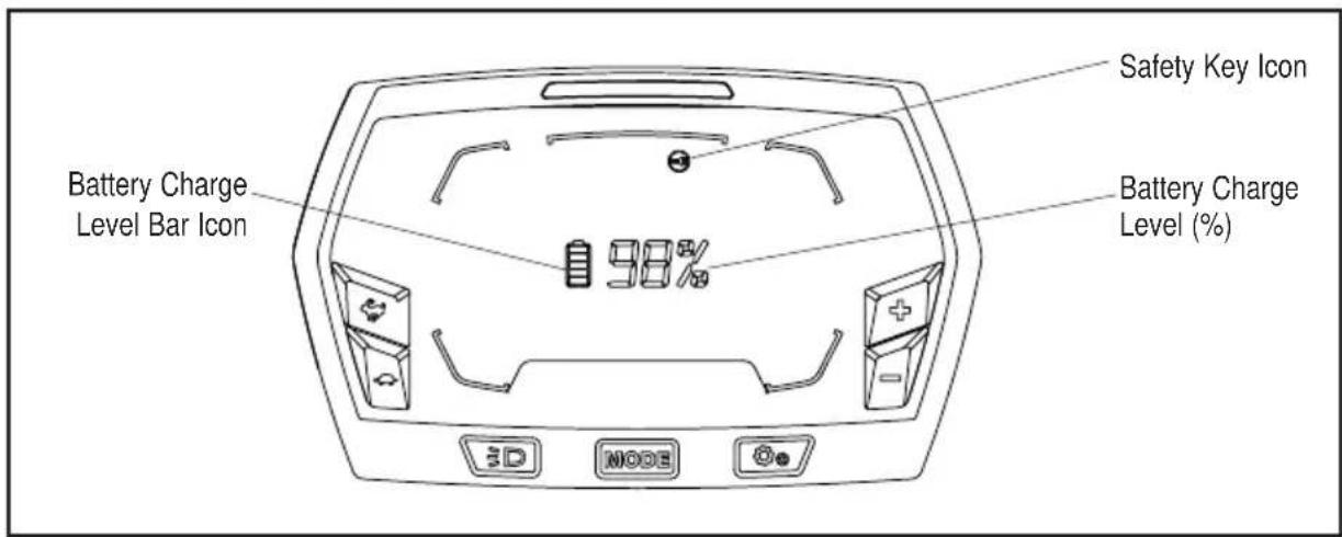
text_image
Battery Charge Level Bar Icon Safety Key Icon Battery Charge Level (%) 98% 3D MODESafety Key Icon
“ [icon] ” illuminates and flashes as a warning to instruct the operator to insert the safety key.
Battery Charge Level Icons
The remaining battery charge level is shown with the battery bar icon and also as a percentage (%). The battery bar icon will flash when the mower is being charged.
LCD "On mode" Screen

text_image
13 211214111098 7 LOW POWER ON/OLOAD 180% PWR CONTROL STANDARD 5 3 4 MODE 6 41) Auto Hold Icon 8) Low Power Indicator, Overload
2) Hour Meter Indicator
3) Blade Speed Indicator 9) Error Code Indicator
4) Safety Device Status Indicator Icons 10) Load Indicator
“(A)” flashes and alarm will sound if operator leaves the seat with machine stopped on a slope without setting the parking brake. Apply parking brake to stop the alarm.
Hour Meter
- Shows the total driving time of the mower, in hours. Use the hour meter to determine when the mower has reached the recommended service intervals.
• Hour meter cannot be reset.
Safety Device Status Indicator Icons
“” flashes to instruct the operator to reset the PTO switch. To reset the PTO switch, depress the switch to the ‘OFF’ position, then lift to re-engage the blades.
“(P)” illuminates when the parking brake is set. Flashes when the operator is off the seat and the parking brake is not set.
“iuminates and flashes when the operator is off the seat.
“” flashes to instruct the operator to reset the steering levers to open position.
Overheat Icon
“ 🎨 ” When the battery is overheated, the overheat icon will flash every second. The alarm will sound 5 times. When the mower is overheated, the overheat icon will flash every second. The mower status indicator light, on top of the LCD screen will change to solid red.
It is recommended that the operator should reduce the load of the mower by raising the deck cutting height or slowing the blade/driving speed. Allow the battery pack or the mower to cool.
Low Power Indicator
When the available battery charge is too low, the mower will go into limp home mode. The low power indicator will flash every second. The operator should stop working and return to the battery charging area as soon as possible.
Overload Indicator
When the mower is overloaded, the overload indicator will flash every second. Meanwhile, the mower status indicator light, on top of the LCD screen will change to solid red.
It is recommended that the operator should raise the deck cutting height to reduce the load of the mower when the overload indicator flashes.
Error Code Indicator
The on-board computer system will take action to protect the operator and the machine when it detects an issue. When it acts to turn off the machine or a component, it will indicate that a fault has occurred, and that fault code will be shown on the LCD screen. Refer to the "Error code & status indicator table" in the "TROUBLESHOOTING" section of this manual for more information.
Load Indicator
Indicates the current load of the mower. When the load is in the ECO range, the mower is under normal load. When the load is in the PWR range, the mower is under heavy load.
Battery Icon
“shows available charge stored in battery.
USB Icon
“” illuminates to indicate that a USB device can work after the mower is started correctly.
Mower Status Indicator
Normally illuminated green colour. Changes to red if there is a warning or error code displayed on the LCD screen.
Headlights Icon
“≡D illuminates when the headlights have been turned on.
Limp Home Mode
When the available battery charge is very low, the mower will go into limp home mode. The low power indicator will flash on the LCD screen. Blades will stop automatically, and can't be turned on until the mower is recharged. The maximum distance the mower can travel in limp home mode is 1.5Km. The operator should stop working and return to the battery charging area as soon as possible.
NOTICE: If it is required to manually push the machine:
- Apply the parking brake.
- Hold the Start/Stop button down to turn off the machine.
- Wait approximately 3 seconds for Start/Stop button LED to go off.
- Release the parking brake.
Safety Start Interlock System
The mower is equipped with a safety start interlock system consisting of the safety key, start/stop button, the parking brake pedal switch, seat switch, and charging port switch.
The safety start interlock system is designed to protect the operator and others from accidental injury due to unintentional mower starting.

WARNING: Check the mower safety start interlock system prior to operation. This system is an important mower safety feature. It should be repaired immediately if it malfunctions: contact an authorised Victa service centre immediately

WARNING: The safety start interlock system must not be disconnected or bypassed. Doing so could cause the mower to operate unexpectedly, resulting in personal injury.
Indicator Alarm
The mower is equipped with an indicator alarm that will beep. It will sound when:
- The available battery charge is too low, the mower will go into limp home mode, the alarm will continue to sound.
- A fault code is displayed on the LCD screen, the alarm will sound 5 times.
- Operator is off the seat without locking the parking brake pedal into the parked position, the alarm will sound continuously to remind the operator to set the parking brake for safety.
Mower Status Indicator Light
When the error code is displayed on the LCD screen, the indicator light will change to solid red.
Unpacking

WARNING: To reduce the risk of injury or mower damage, do not use a knife to cut the nylon straps. Use scissors or side cutters.

WARNING: To reduce the risk of damage, remove watches or other fragile and valuable items from your wrists. There's a risk of accidental contact with steel frame elements.
Recommended tools for unpacking (not included):
- Scissors or box cutters.
- Impact wrench with 13 mm socket.
The mower is shipped in a steel frame covered by a carton, with seat and steering levers separately packed in the steel frame. The operator should remove the packaging from the steel frame first and then mount the seat and steering levers onto the mower as follows:
- Remove the carton from the steel frame.
- Cut the nylon straps and remove the accessory box located in the seat area of the mower and remove the two open-end wrenches inside.
- Use the two supplied open-end wrenches to loosen all the bolts that secure the side frames, front frame, back frame, and the two mower rear wheels from the bottom frame. Remove and store the disassembled frames in a safe area to avoid tripping hazard. Consult your local waste authority for information regarding available recycling and/or steel disposal options on the frames.
NOTE: To speed up the process use an impact wrench with a 13 mm socket.
- Cut the nylon straps securing the charger boxes, seat, accessory box, mower front wheels and rear wheels.
- Remove the accessory box which located under the foot pedal, then remove the seat assembly and charger box from the mower.
- Remove and set aside all accessible packaging and wrap. Do not discard the packing material until you have carefully inspected and satisfactorily operated the product.
- If a ramp is available, position a full-width ramp against the bottom frame, close to the front wheel. Do not exceed the maximum recommend operating angle of 15^ .
- Release the parking brake pedal from the braking position. Refer to section "Setting the Parking Brake" in the "OPERATING INSTRUCTIONS" section of this manual.
NOTE: A significant effort is required to release the parking brake pedal by hand. Push hard.
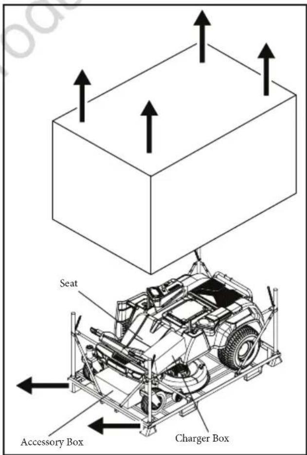
text_image
Seat Accessory Box Charger Box- Two persons are recommended: One person should stand in front, and pull and steer the mower forward, pulling by the mower frame. The 2nd person should stand at the back of the mower, pushing the mower by its frame.

CAUTION: Heavy object. Team work required. At least two persons are required to push and pull this mower out of the shipping frame.
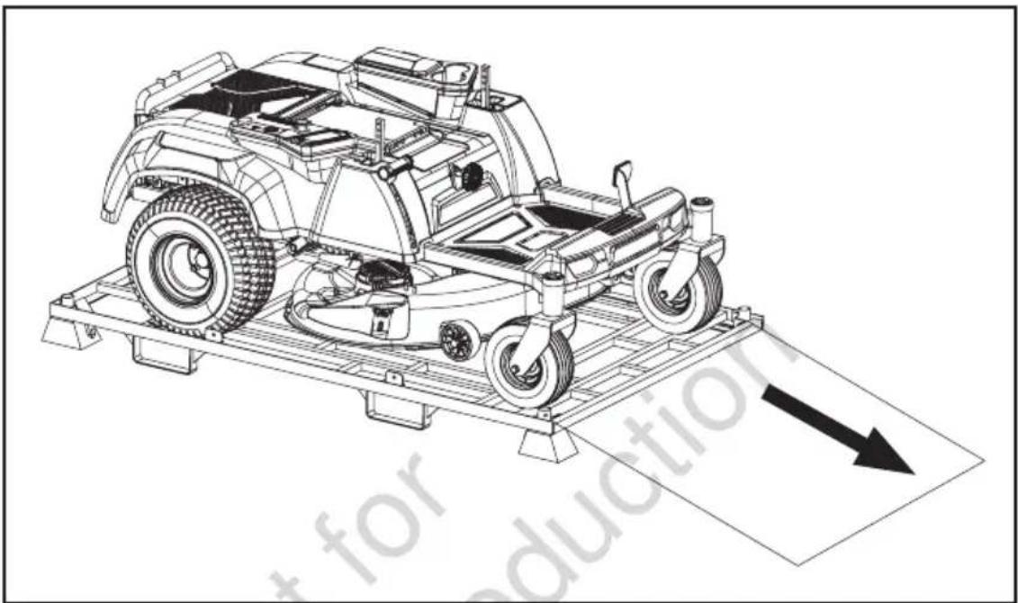
natural_image
Technical line drawing of a car chassis on a platform with an arrow indicating direction (no text or symbols present)
NOTICE: PULL THE MOWER FORWARD. Pulling the mower backward from the steel frame will cause the mower to catch in the bottom frame and may damage the mower's cutting deck.
Always remove the mower from the frame in the forward direction. Use of a sturdy ramp, or a 2x4 block of wood placed on the ground against the front of the shipping frame will help when moving the mower off the shipping frame.

WARNING: Do not use this product if any parts on the packing list are already assembled to your product when you unpack it. Parts on this list are not assembled to the product by the manufacturer and require customer installation. Use of a product that may have been improperly assembled could result in serious personal injury.
- Inspect the product carefully to make sure that no breakage or damage occurred during shipping.
- If any parts are damaged or missing, please contact retailer, or authorised Victa service centre.
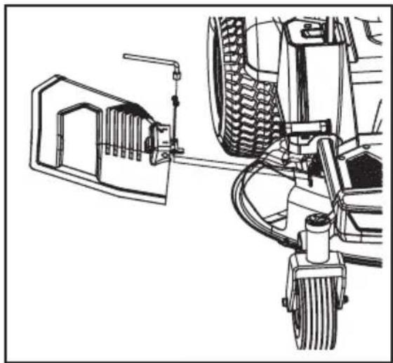
Installing Side Discharge Chute

WARNING: Operating the mower without side discharge chute in place will result in serious personal injury. Mounting the side discharge chute is critical for safe operation.
- Adjust the deck to the lowest cutting height.
- Assemble the bracket of the side discharge chute kit to the 2 welded bolts on the deck, tighten 2pcs nuts with socket wrench supplied.
NOTICE: Make sure that there is no gap between the bracket and the deck after tightening.
natural_image
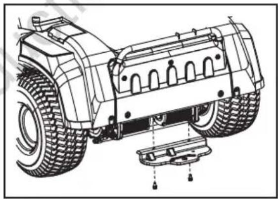
Technical line drawing of a vehicle's front wheel assembly and suspension mechanism (no text or symbols)Installing Tow Hitch
Align the hitch bracket to the rear frame of the mower, then use the supplied socket wrench to secure the bracket with the two supplied Hex bolt with washer.
NOTICE: Make sure that there is no gap between the bracket and the mower frame after tightening.
natural_image
Technical line drawing of a vehicle's front wheel assembly with mounting base (no text or symbols)Installing Seat
The mower incorporates a separate seat switch that will stop the drive motors and deck motors when the operator is unseated for any reason while the mower is operating. This is a safety feature designed to prevent runaway or accidental entanglement.

WARNING: The safety interlock system must not be disconnected or bypassed. Doing so could cause the mower to operate unexpectedly, resulting in personal injury.
- Remove the four socket head screws from the accessory box and set them aside.
-
Lay the seat assembly on its side and insert the cable plug into the socket on the bottom of the seat. This connects the safety interlock system.
-
Rotate the two arm rests to the horizontal position. Place the seat closely against the front of the suspension base. Align the two mounting holes in the seat with the holes in suspension base, and use the supplied allen key to lock them together with the two supplied socket head screws.

natural_image
Technical line drawing of a mechanical assembly with no visible text or symbols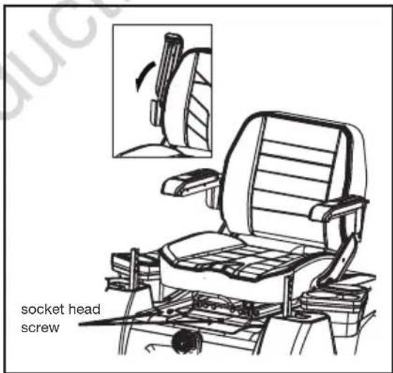
text_image
socket head screw- Lift the seat forward-back adjustment lever slightly and pull the seat forward to expose the two backside mounting holes in the steel rails of the seat assembly. Use the supplied allen key to thoroughly tighten the steel rails onto the suspension base with the remaining two socket head screws.
natural_image
Technical line drawing of a vehicle chassis frame with no visible text or symbols
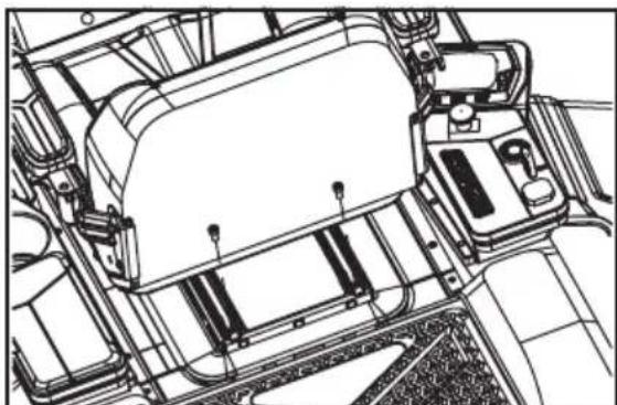
WARNING: When finished tightening the two backside screws, please check that there is no gap between the front part of the steel rails and the suspension base.
Attaching Mulching Cover
- To set up the mower for mulching, lift the side discharge chute first, then hook the mulching cover onto the deck opening at the spots 1, 2, and 3. Make sure that all the hooks are securely fastened in their places and prevent the mulching cover from moving. Leave the side discharge chute in the open position.
- To remove the mulching cover, separate the movable spring of the mulching cover from the hook on the deck first and then remove it from the deck opening. Lower the side discharge chute slowly until it rests firmly against the deck.

text_image
Side Discharge Chute Movable Spring Mulching CoverFitting Steering Levers
-
Remove the four hex bolts from the accessory box and set them aside.
-
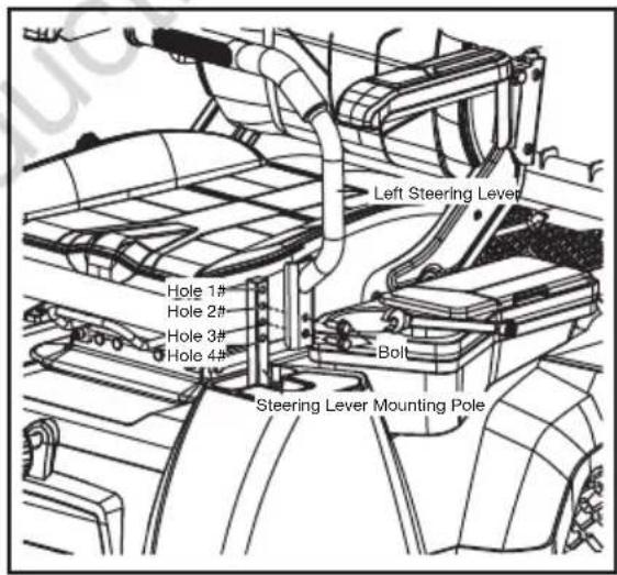
Lift one steering lever to align the holes in the steering lever with the holes in the corresponding mounting pole. Select the preferred steering lever operating height, and then use the supplied open-end wrench to secure the steering lever with the two supplied hex bolts as indicated below.
- Hole 1 & 2: upper fixing holes for steering lever.
- Hole 2 & 3: middle fixing holes for steering lever.
-
Hole 3 & 4: lower fixing holes for steering lever.
-
Assemble the other steering lever and tighten with the remaining two hex bolts in the same way
text_image
Left Steering Lever Hole 1# Hole 2# Hole 3# Hole 4# Bolt Steering Lever Mounting PoleNOTICE: The left and right steering levers should be adjusted so that they align with each other when in the neutral position. NEVER install the steering levers in an asymmetrical operating height.
Before Operating

WARNING: Do not allow familiarity with this product to make you careless. Remember that a careless fraction of a second is sufficient to inflict serious injury.

WARNING: Do not use any attachments or accessories not recommended by the manufacturer of this product. The use of attachments or accessories not recommended can result in serious personal injury.
CHECK THE TYRE PRESSURE
Check the air pressure in all tyres before use. Improper air pressure will affect handling, steering response, traction, tyre life, level cutting, and operator comfort. Be sure tyres are inflated to the pressure in the specification table on page 52 of this manual.
NOTICE: Tyre pressure should only be measured or adjusted when tyres are cold.

WARNING: Check the tyre pressure carefully while inflating. Too much air in the tyre could cause the tyre to burst, causing serious personal injury.
VERIFY MOWER CONDITION
Inspect the entire product for damaged, missing, or loose parts such as screws, nuts, bolts, caps, etc. Tighten securely all fasteners and caps and do not operate this product until any missing or damaged parts are replaced.
The mower incorporates a separate seat switch that will stop the drive motors and deck motors when the operator is unseated for any reason while the mower is operating. This is a safety feature designed to prevent runaway or accidental entanglement. Test the system to be sure it is working correctly.
- Position the mower on a level surface.
- The operator must be on the seat when testing the seat switch.
- Release the parking brake pedal. Keep the steering levers in the open position.
- Insert the safety key into the mower. Press and hold the start/stop button for 1 to 2 seconds to illuminate the LCD screen.
- Pull the PTO switch upward to engage the blade motors.
- Slowly raise yourself off of the seat, but do not get off the mower. The deck blade system should stop.
- If the cutting blade system fails to stop when
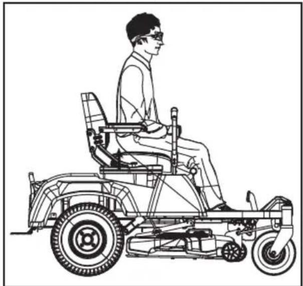
natural_image
Line drawing of a person riding a three-wheeled electric vehicle (no text or symbols)Before Operating
the operator is off of the seat and if the cause cannot be determined after confirming the cover and socket connection of the seat is well connected, contact an authorised Victa service centre immediately.
- Push the PTO switch downward to disengage the blade motors and adjust the steering levers from open position to neutral position.
- Adjust the steering levers forward or backward to drive the mower; refer to the "Operating the Mower" section of the operating instructions below.
- Slowly raise yourself off of the seat. The drive system should stop.
- If the drive system fails to stop when the operator is off of the seat and if the cause cannot be determined after confirming the cover and socket connection of the seat is well connected, contact an authorised Victa service centre.

WARNING: DO NOT operate the mower until the safety interlock system has been repaired by a qualified service technician.
Cutting Deck Height Adjustment
NOTICE: The mower's deck is set in the highest cutting height when it is shipped. Before using the mower, the operator should adjust the deck height to the cutting position best suited for the lawn.
NOTICE: To prevent scalping the lawn when encountering high spots, the two anti-scalp wheels can be adjusted when the mower is at the desired cutting height. Depending on your desired cutting height, you may need to change the position of the anti-scalp wheels. please refer to "Adjusting the anti-scalp wheels" in the "MAINTENANCE" section of this manual.
-
Make sure that the safety key has been removed from the mower before making any adjustments.
-
To lower the cutting height, grasp the deck height adjustment lever and move it inwards to disengage it from the slot. Move it downward and engage it into the slot when it arrives at the desired cutting height.
-
To raise the cutting height, grasp the deck height adjustment lever and move it inwards to disengage it from the slot. Move it upward and engage it into the slot when it arrives the desired cutting height.

natural_image
Technical line drawing of a mechanical assembly with no visible text or symbolsNOTICE: Prior to mowing, the deck should be adjusted to sufficient height to avoid stumps, rocks or other obstacles that can damage the mower deck.

DANGER: Never attempt to make any adjustments to the mower deck while the mower is driving or the cutting blade is engaged. Mower blades cannot be seen and are located very close to the deck housing. Fingers and toes can be cut off instantly.

WARNING: Hold the deck height adjustment lever firmly when setting the deck height and only release when it is securely engaged in the desired slot. Quickly letting go of the lever may create a pinching or pulling hazard to the operator's hand.
Seat Adjustment

WARNING: Be sure the seat is secured to the mower with the included socket head screws before operating the mower. A seat that is not secure can cause the operator to lose control of the mower and result in possible death or serious personal injury.
Adjust the seat position to ensure you are able to make firm contact with the parking brake pedal before operating the mower. The seat can be adjusted forward and rearward by lifting the seat forward-back adjustment lever under the seat.
- Set the parking brake.
- Sit down on the seat; lift the seat forward-back adjustment lever and hold it, then move the seat forward or backward to the desired position.
- Release the seat forward-back adjustment lever and ensure that the seat is locked in position.
- The comfort of the seat can also be adjusted with the seat suspension adjustment knob on the underside of the seat. Loosen or tighten the adjustment knob as indicated to achieve the most comfortable suspension.
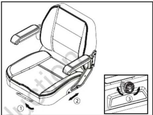
text_image
Technical diagram of a vehicle seat assembly with numbered parts and directional arrows indicating motion or assembly steps.Setting the Parking Brake
The parking brake pedal is used to lock the mower in the braking position. To start the mower, it should be released from the braking position.
To set the parking brake:
- Place the steering levers back in the neutral position and open them outwards to the open position.
- Use your left foot to fully depress and hold the parking brake pedal until the pedal locks into place.
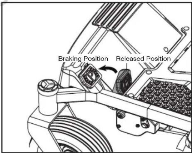
text_image
Braking Position Released Position- The pedal should stay in place. Remove your foot from the parking brake pedal.
To release the parking brake:
Depress the parking brake pedal once again, the pedal will rebound to the released position.

WARNING: Never leave the mower unattended during work breaks without verifying that the parking brake is set and the safety key is removed. Failure to set the parking brake could cause the mower to move. Leaving the safety key in place may allow unauthorised use that could result in serious personal injury.
Charging
When battery charge becomes low, the mower will go into limp home mode and will permit the mower to travel a maximum distance of 1.5 km back to the battery charging area. The blades are automatically stopped to save the battery charge.

WARNING: Do not attempt to drive across roads or railways when battery charge level is low. DO NOT attempt to charge the battery or the mower with a charger not designed for use with this product.

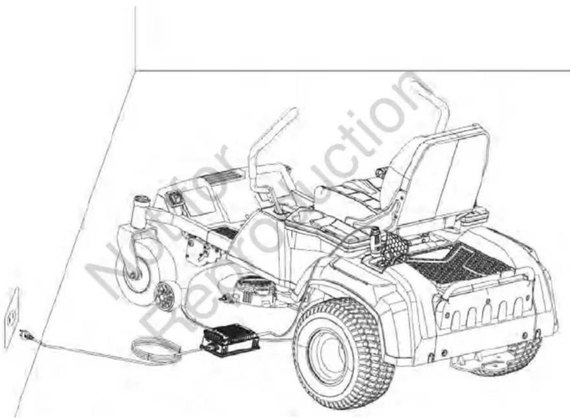
text_image
LOCK CAPDUST CAP CHARGING PORTCharging the battery via charging port.
The battery charging port is located on the left housing of the mower, next to the storage box. To charge the battery,
- Stop the mower and remove the safety key. Make sure that the mower comes to a complete stop.
- Lift the dust cap and lock cap from the battery charging port on the mower and connect the charger plug into the port. The locking cap tab must be seated into the charger plug for a correct fit.
- Plug the other end of the charger into a household outlet.
- The charger will start to charge the battery. Once the battery is fully charged, as indicated on the LCD screen, disconnect the charger plug from the wall outlet and remove the charger plug from the port.
- Close the charger port with the dust cap and lock cap and begin operating the mower.
NOTICE: Plug will only fit one way into the port. Make sure it is properly aligned before inserting.

WARNING: Do not smoke while charging the mower.
WARNING: The mower should be charged under a covered area out of the rain or indoors.
• Lithium-ion batteries do not develop a memory and do not need to be fully discharged before recharging.
- When storing, the mower should be charged to 100% at least once every 6 months for longest possible battery life.
- When charging, be sure that the charger cooling fan inlet and outlet are not blocked.
natural_image
Line drawing of a small utility vehicle with visible wheels and suspension components, enclosed in a 3D coordinate system (no text or symbols)Intended Use
This machine is designed to be used in the open air only as a lawnmower for lawns and grassed area in gardens and in compliance with the safety and operating instructions indicated in this manual.
Any other use should be deemed "hazardous" and shall invalidate the warranty and relieve the manufacturer of all liability.

HAZARD! This machine is not allowed to circulate on public roads and is not approved to transport persons.
Before Starting the Mower
- Ensure that the work area is clear of children, bystanders, and pets.
- Clear the work area of objects that may be thrown by the mower blades.
- Clean debris from mower.
- Check for loose fasteners.
- Check to make sure that all guards are in place and working properly.
- Check the tyre pressure.
- Check the brake operation.
- Test the safety interlock system.
- Adjust the deck height to the desired cutting position best suited for the lawn.
- Adjust the seat to desired position.
- Verify the battery charge level.
Starting the Mower
Operating a zero turn mower is different from operating a standard ride-on mower. Zero turn mowers are rear wheel drive and the wheels operate independently as directed by the position of the steering levers. Before you begin to mow your grass, we strongly encourage you to find a large, level, and open area to practice operating the mower using the instructions that follow. Once you can comfortably and reliably perform each of these manoeuvres, you are ready to begin mowing.
- Ensure parking brake is on. Insert the safety key.
- With the safety key inserted, press and hold the start/stop button for 1 to 2 seconds to illuminate the LCD screen.
- Check for the appropriate driving mode by pressing the driving mode button (CONTROL/STANDARD) and select the driving speed using the driving speed buttons.
NOTICE: It is always recommended to start the mower in the slowest driving speed.
- Release the parking brake pedal from the braking position and move the two steering levers inward from the open position to the neutral position. You are ready to manoeuvre the steering levers to drive the mower.
- Pull the PTO switch to start the cutting blades.
- Push the steering levers forward for forward motion and pull back for reverse motion.

WARNING: Clear the area of bystanders before operating the mower. If anyone enters the mowing area, stop immediately and do not continue mowing until the bystanders leave the area.

WARNING: Avoid sudden starts, stops, and turns, as well as excessive speed, especially when first learning to operate the mower. The mower can spin rapidly, which may cause you to lose control and could result in death, serious personal injury and/or damage to the mower.
Press the driving speed adjustment button to the lowest speed (refer to "Driving Speed Adjustment Button" in the "PARTS & CONTROLS" section of this manual) to limit the amount of speed available until you are fully capable of operating the mower in all situations.
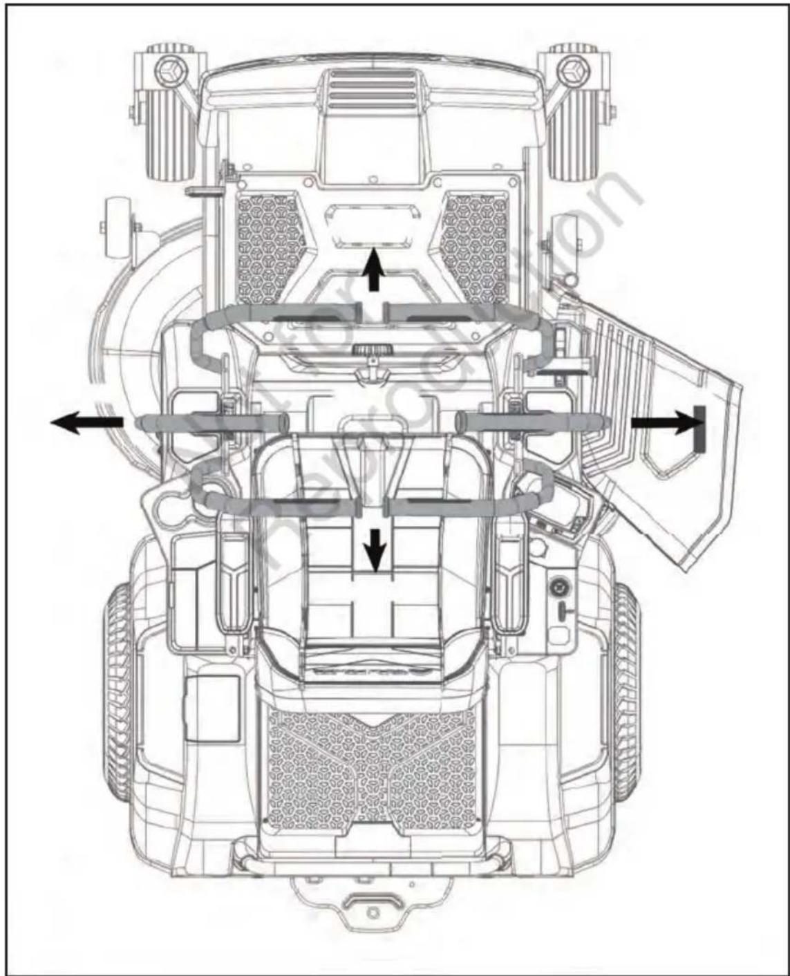
natural_image
Technical line drawing of a vehicle's top-down view showing internal components and airflow paths (no text or labels)Stopping the Mower

WARNING: Never make sudden stops or sudden direction reverses, especially when manoeuvring on a slope. The steering levers are designed for sensitive response. Rapid movement of the steering levers in either direction could result in a reaction of the mower that can cause serious injury.
- Return the steering levers to the Neutral Position.
- Push the PTO switch downward to disengage the deck motors/mower's cutting blades.
- Open the steering levers outward into the stop position.
- Set the parking brake pedal to the braking position.
- Press the start/stop button for more than 1 to 2 seconds to turn off the mower.
- Remove the safety key from the mower and keep it in a safe place.

WARNING: After more than 1 hour without operating, the mower will automatically shut off.

WARNING: Do not stop the mower on a slope. Always stop the mower on a flat, level surface and never leave the mower unattended with the safety key inserted, even just for a brief period. Leaving the safety key may allow unauthorised use that could result in serious personal injury.

WARNING: When the mower stops driving on a slope and the operator is off the seat without setting the parking brake pedal at the braking position, the alarm will sound continuously to remind the operator to set the parking brake for safe mower stopping on the slope. Always set the parking brake pedal at the braking position when leaving the seat.
Otherwise the mower could slide down the slope, which may cause serious mower damage or personal injury!
Operating the Mower
After starting the mower, engage the steering levers as follows
• To go forward, push steering levers forward an equal distance.
- To go in reverse, pull steering levers rearward an equal distance.
• To turn left, move the right steering levers farther from neutral than the left steering lever.
• To turn right, move the left steering levers farther from neutral than the right steering lever.
- To execute a zero-radius turn, slow down first and then move one steering lever forward and the other steering lever back of neutral. This allows the drive (rear) wheels to counter-rotate.

WARNING: Rapid movement of steering levers is not recommended as damage to the electric components of the mower may occur.

WARNING: Aggressive turning can scuff or damage lawns. Perform zero turns at low driving speed. Always keep both wheels rotating when making sharp turns. Do not make turns with inside wheel completely stopped. For minimum turning radius, slowly reverse the inside wheel while moving the outside wheel slowly forward.
- To stop or decrease speed, move the steering levers to neutral. When going forward, pull back gently on the steering levers. When going in reverse, push forward gently on the steering levers.

flowchart
graph TD
    A["FORWARD"] --> B["OPEN"]
    B --> C["NEUTRAL"]
    C --> D["OPEN"]
    D --> E["REVERSE"]
    E --> F["MOVE BOTH levers towards NEUTRA L position to slow down or stop the mower"]
    G["Parking Brake"] --> H["Releve Parking Brake before engaging drive levers"]
    I["Parking Brake On"] --> J["Push the brake pedal down to engage e"]
    I --> K["Parking Brake Off"]
- To increase speed, increase the steering lever's distance from neutral. The farther forward the steering levers are from the neutral, the faster the mower will travel forward. The farther back the steering levers are from the neutral, the faster the mower will go in reverse.

WARNING: Stay at least two mowing widths (2m) away from any ditches, drop-offs, or water. Front wheels can rotate when the mower is stopped, even with the brake applied, and cause the mower to go over the edge or into the water and result in death or serious personal injury.

WARNING: Be aware of what is behind the mower before backing up. DO NOT mow in reverse unless absolutely necessary. Always look down and behind before and while backing to make sure no children, bystanders, or pets enter the mowing area. Remember that a careless fraction of a second is sufficient to inflict death or serious injury.

WARNING: Be certain you have correctly set your intended direction of travel with the steering levers before depressing the parking brake pedal. Failure to do so could result in you driving the mower in an unintended direction, which could cause loss of control or an accident.

WARNING: Be cautious when crossing over gravel paths or driveways. Before crossing, disengage the blades and raise the cutting deck to the highest position to minimise the possibility of ricochet. Drive slowly to avoid loss of traction and control.
Mowing Tips
NOTE: A sharp blade will greatly enhance the performance of the mower, especially when cutting tall grass. Make sure to check the sharpness of the blade before mowing.
- Verify that the lawn is free of stones, sticks, wires, and other objects which could damage the mower's cutting blades or motors. Such objects could be accidentally thrown by the mower in any direction and could cause serious personal injury to the operator and to others.

WARNING: If you strike a foreign object, stop the mower and blades. Thoroughly inspect the mower for any damage and repair the damage before restarting and operating the mower. Excessive vibration of the mower during operation is an indication of damage. The unit should be promptly inspected and repaired.
- The mowing result will be the best with a high cutting blade speed and low driving speed. If the grass is not too long and dense, the driving speed can be increased without negatively affecting the mowing result.
- When cutting heavy grass, reduce the driving speed to allow for a more effective cutting and a proper discharge of the clippings.
- Begin with a high cutting height and reduce it until the desired mowing result is attained. Grass over 6 inches long should be mowed twice, at successively lower cutting heights.
- To maintain a healthy lawn, cut off only one-third or less of the total length of the grass. The average lawn should be approximately 4-5cm long during cool month and between 5-8cm long during hot months. For healthier and better looking lawns, mow more often after moderate growth.

natural_image
Diagram of a microfluidic device with wavy membrane layers and particles emitting flow (no text or symbols)- Do not cut wet grass. Mowing on wet surfaces can cause loss of control and the wheels to sink into the soft lawn. Wet grass will stick to the underside of the deck and prevent proper bagging or mulching of the grass clippings.
- New or thick grass may require a narrower cut or a higher cutting height.
- Keep the mower deck and side discharge chute clean. Remove grass clippings, leaves, dirt, and any other accumulated debris before and after each use. See section "Cleaning the Mower" in the "MAINTENANCE" section of this manual.
- When the mulching cover is used, it is important to mow frequently.
Operating on a Slope

WARNING: If you strike a foreign object, stop the motors and remove the safety key. Thoroughly inspect the mower for any damage and repair the damage before restarting and operating the mower. Excessive vibration of the mower during operation is an indication of damage. The unit should be promptly inspected and repaired.

text_image
Sight and hold the line level with a vertical tree... Sight and hold the line level with a pole... Or a corner of a building... Or a fence post... 15 Degrees- Mow up and down, not across the face of slopes.
- Do not mow on wet grass. Wet grass can cause the tyres to lose traction or slip on slopes, even though the brakes are functioning properly.
- Watch for holes, ruts, rocks, hidden objects, or bumps which can cause you to slip or trip. Tall grass can hide obstacles. Remove all objects such as rocks, tree limbs, etc., which could be tripped over or thrown by the blade.
- Do not mow near drop-offs, ditches, or embankments.
- Drive slowly and do not make sudden changes in speed or direction.
- Avoid stopping on a slope if possible. If stopping on a slope is unavoidable, make sure to engage parking brake. When restarting, use the lowest possible speed. If turning is necessary, exercise extreme caution when changing direction and always turn downhill.
- If at any point the tyres lose traction while operating on a slope, disengage the blades and proceed slowly and carefully straight down the slope.
WARNING: Before performing any maintenance, stop the mower on a level surface and wait for the blades to come to a complete stop. Set the parking brake and remove the safety key to avoid accidental starting and possible serious personal injury.

WARNING: Always wear eye protection with side shields marked to comply with ANSI Z87.1. Failure to do so could result in objects being thrown into your eyes resulting in possible serious injury.

WARNING: When servicing, use only identical replacement parts. Use of any other parts may create a hazard or cause product damage. To ensure safety and reliability, all repairs should be performed by a qualified service technician.
WARNING: Strictly adhere to all torque wrench tightening specifications. Failure to do so could cause serious personal injury.

WARNING: Remain alert for unusual noises, as they could be signalling a problem. Visually inspect the product for any abnormal wear or damage. Periodically inspect the entire product for damaged, missing, or loose parts such as screws, nuts, bolts, caps, etc, along with wire and string tangles. Tighten securely all fasteners and caps and do not operate this product until all missing or damaged parts are replaced.
Recommended Maintenance Schedules
| Maintenance Service Interval | Maintenance Procedure |
| Before each use or daily • | Check the safety interlock system.Visually inspect to see if the tyres are correctly inflated.Inspect the blades.Inspect the entire product for damaged, missing, or loose parts such as side discharge chute, screws, nuts, bolts, caps, etc., ensuring that all guards are in place and working properly. |
| After each use | Clean the mower deck. |
| Every 25 hours | Check tyre pressure. |
| Every 100 hours | Check the rear wheels, ensuring that the 4 lug nuts are fastened at the recommended torque. |
| Every 200 hours | Check the front wheels, ensuring that they turn freely. |
| Before storage | Remove the safety key from the mower.Perform all maintenance procedures listed above and thoroughly clean the mower.Inspect the entire product for damaged, missing, or loose parts, replace or tighten the corresponding ones before storage. |
| Annually | Check the parking brake pedal. Remove the safety key and set the parking pedal at the braking position. Manually push the mower forwards to see whether the mower can be moved or not. If it moves, have it serviced by a qualified service technician. |
General Maintenance
- Avoid using solvents when cleaning plastic parts. Most plastics are susceptible to damage from various types of commercial solvents and may be damaged by their use. Use clean cloths to remove dirt, dust, oil, grease, etc. Insect repellent spray may damage plastic and painted surfaces. Do not spray insect repellent near the mower.
- Prolonged exposure to sunlight will damage some surfaces.
- If the mower is left out in the rain accidentally, use dry clean cloths to dry the seat, control panel, etc., before you restart it or store it.

WARNING: Do not at any time let brake fluids, gasoline, petroleum-based products, penetrating oils, etc. come in contact with plastic parts. Chemicals can damage, weaken, or destroy plastic which can result in serious personal injury.
Cleaning the Mower
Remove any build-up of grass and leaves on or around the mower housing. Wear eye protection and use compressed air after each use to clean the mower housing or the top side of the mower deck.
The underside of mower deck should also be cleaned using wash port after each use, as grass clippings, leaves, dirt, and other debris will accumulate, especially when grass is wet or has high moisture content. This accumulation is undesirable, as it will harden, restricting blade and air movement, probably resulting in a poorer quality of cut and even promoting rust and corrosion.
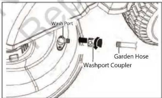
text_image
Wash Port Garden Hose Washport CouplerUSING WASH PORT TO CLEAN MOWER DECK

WARNING: Follow this procedure after EACH USE to prevent buildup and remove corrosive lawn chemicals.

WARNING: You can wash the machine with a mild detergent and water. Do not pressure wash the machine. Avoid excessive use of water, especially near the control panel, under the seat, around the motors and all electric components and bearings.
- Set the parking brake pedal to the braking position. Refer to "Setting the Parking Brake" in the "OPERATING INSTRUCTIONS" section of this manual. Park on a flat level surface.
- Adjust the cutting deck height to the lowest setting. Refer to "Cutting Deck Height Adjustment" in the "OPERATING INSTRUCTIONS" section of this manual.
- Attach the supplied wash port quick-coupler to garden hose.
- Attach garden hose with quick-coupler to wash port on the mower deck. The wash port is on the left side of the mower deck.
- Turn on the water.
- Pull the PTO switch up to start the mower cutting blades and adjust the blade speed to the highest. Refer to "Blade Speed adjustment Button" in the "PARTS & CONTROLS" section of this manual.
- Flush water under the deck for approximately one minute.
- Disengage the mower blades by pushing the PTO switch downward.
- Turn off the water and remove garden hose and quick-coupler from wash port.
- Remove quick-coupler from garden hose and store for future use.
- Turn off the mower completely. See section "Stopping the Mower" in the "OPERATING INSTRUCTIONS" section of this manual
NOTE: When cleaning the deck using the wash port, the mower can be either in mulching or side discharging mode.
NOTE: If the mower is not clean after one wash cycle, repeat the process until the deck is thoroughly cleaned.
Adjusting the Anti-Scalp Wheels
text_image
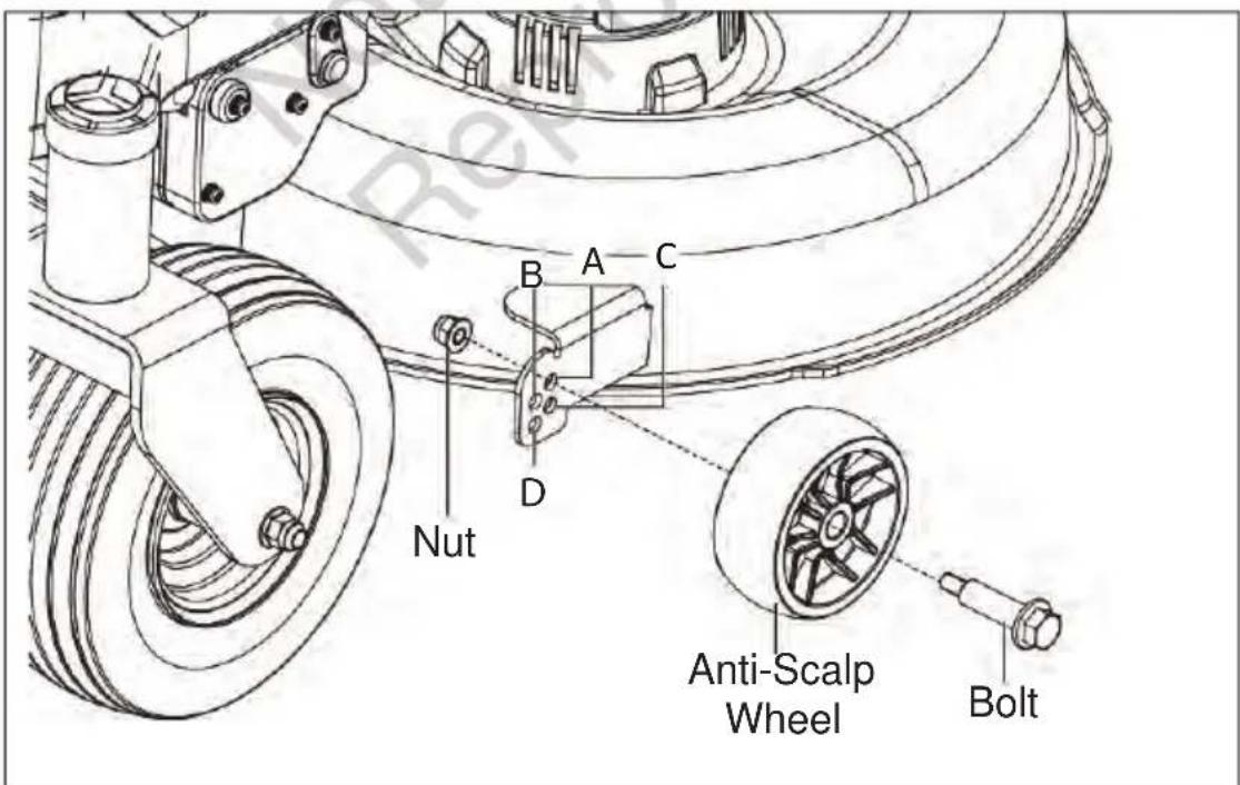
Nut A B C D Anti-Scalp Wheel BoltADJUSTING THE ANTI-SCALP WHEELS
The anti-scalp wheels are designed to minimise the chance of scalping the lawn when mowing on rough, uneven terrain. After setting the cutting height, adjust the anti-scalp wheels so they extend below the deck but do not contact the ground.
The anti-scalp wheels can be set in one of four positions:
- Position A: less than 50mm in grass cutting height
- Position B: 50-75mm in grass cutting height
- Position C: 75-100mm in grass cutting height
- Position D: greater than 100mm in grass cutting height
The anti-scalp wheels are set at Position A by default in production. They are held in place by one nut and lag bolt each.
NOTE: One 16 mm wrench and one 21 mm wrench are required to adjust the wheels.
- Park the mower on a level surface and set the parking brake.
- Stop the motors and remove the safety key. Allow the cutting blades to come to a complete stop.
- Raise the deck to the desired cutting height.
- Use 16 mm wrench to stabilise the nut first and then loosen and remove the lag bolt on the other side with 21 mm wrench.
- Move the anti-scalp wheel to the desired position. Then, tighten the lag bolt and nut securely with the wrenches.
- Repeat with the other anti-scalp wheel, making sure both wheels are installed in the same position.
Adjusting the Blades (Front to Rear)
NOTE: Always level the deck side-to-side before making a front-to-rear adjustment.
- Park the mower on a level surface and set the parking brake.

text_image
Blades front to rear- Measure the distance from the tip of one blade to the ground. For best results, the front tip of the blade should be from 1/8 in to 3/8 in (2mm to 10mm) lower than the rear tip.
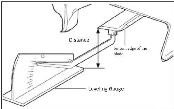
text_image
Distance bottom edge of the blade Leveling Gauge
text_image
Nut Suspension Link- Measure again to verify that the front tip is now 2mm to 10mm lower than the rear tip. If not, continue to adjust and measure until they are.
- Retighten the nuts.
Removing the Mower Deck

WARNING: Make sure that the mower is properly secured and the parking brake is set before proceeding. Raise the deck to the highest cutting height to allow easier access to the blades.

text_image
Deck Height Adjustment Lever 1 Motor Cable Color Pin 2 3 4 Right Side Left sideFollow below steps to remove the mower deck from the product first and then perform maintenance.
- Park the mower on a level surface and set the parking brake.
- Stop the motors and remove the safety key. Allow the cutting blades to come to a complete stop.
- Adjust the deck height adjustment lever to the lowest cutting height position.
- Disconnect both blade motor cables.
- Place a rug or a mat (similar in size to that of the deck) under the deck to prevent damage to the deck.
- Remove the cotter pins and push the shaft pins out. Save both sets for deck re-assembly.
- Remove the cotter pin and washer then push the suspension linkage out to release it from the deck.
- Push the deck sideways and remove it from under the mower
- Clean the deck or replace the blade as directed in "Removing the Blades" and "Installing the Blades" on the next page of this section.
- When the cleaning or blade replacement is complete, reassemble the deck onto the mower in the reverse order.
NOTE: Reconnect the motor cables, ensuring that the left motor cable is connected to the left motor, and the right motor cable to the right motor.

text_image
Blade Motor Cotter Pin Shaff Pin Deck Hook DeckRemoving the Blades

WARNING: Always protect your hands by wearing heavy gloves or wrapping the cutting edges with rags or other materials when performing any maintenance on the mower blade. Always remove the safety key and battery packs when servicing or transporting the mower.
NOTE: The following tools (not included) are required for replacing the blade:
- 15 mm wrench
-
Torque wrench with 15mm sockets
-
Remove the mower deck as section "Removing the Mower Deck" on the previous page of this manual.
- Reverse the deck on the ground with blades facing upward.
- Wedge a block of wood between the blade and mower deck to prevent the blade from turning.
- Use an 15 mm adjustable wrench or socket wrench to turn the blade nut counterclockwise to loosen it.
- Remove the blade nut, cone washer, blade adapter, and blade.
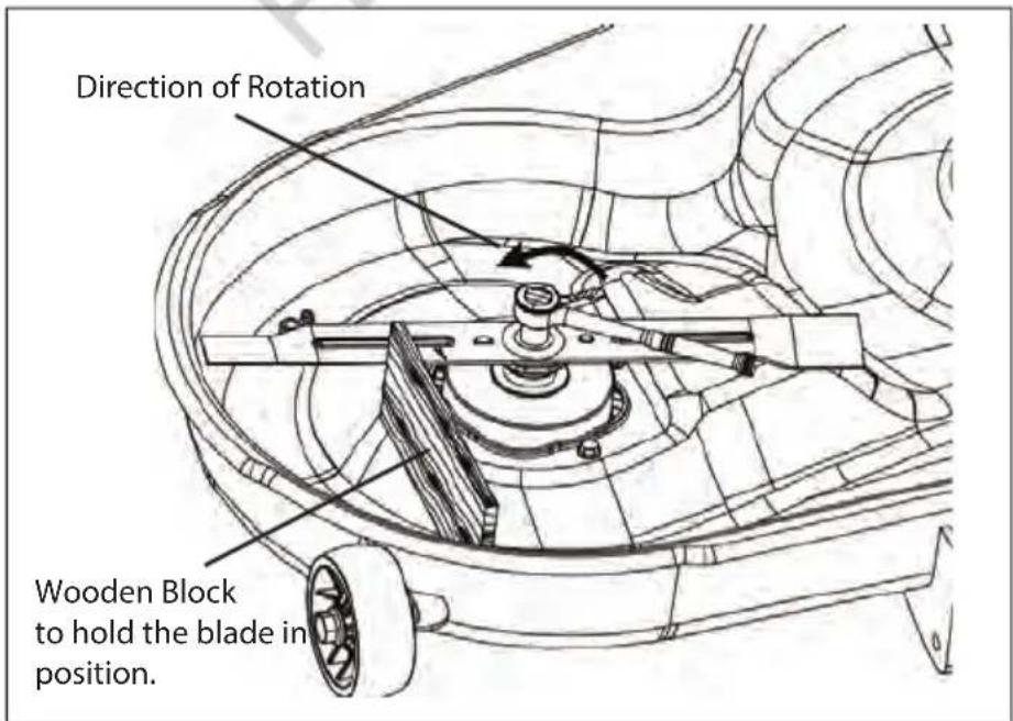
text_image
Direction of Rotation Wooden Block to hold the blade in position.Installing the Blades

WARNING: Always protect your hands by wearing heavy gloves or wrapping the cutting edges with rags or other materials when performing any maintenance on the mower blade. Always remove the safety key and battery packs when servicing or transporting the mower.
NOTE: To re-install or replace the blade, make sure that all parts are replaced in the exact order in which they are removed.
natural_image
Technical line drawing of a mechanical component with no visible text or symbols
text_image
Aligned Holes- Place the new blade on the shaft against the corresponding blade posts. Ensure blade is properly seated with shaft going through centre blade hole and the two blade posts inserted into their respective holes on the blade.
- Place the cone washer onto the blade, make sure the cone washer's opening sits against the blade flat surface.

text_image
Nut Washer Blade Washer Connical Surface- Use a 15 mm torque wrench to tighten the nut clockwise. The recommended torque for the blade bolt is 67-72 N.m.
- Repeat the steps with the second blade, if needed.
- Reassemble the deck onto the mower as directed in "REMOVING THE MOWER DECK" in this manual.

WARNING: Ensure that the blade is properly seated and the blade nut is tightened to the torque specifications above. Failure to properly attach the blade could cause it to come loose and result in possible serious personal injury.
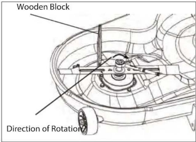
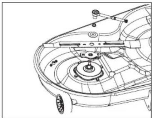
text_image
Wooden Block Direction of RotationChecking the Tyre Pressure
NOTE: Tyre pressure should only be measured or adjusted when tyres are cold.
Check the air pressure in all tyres before use. Improper air pressure will affect handling, steering response, traction, tyre life, level cutting, and operator comfort. Be sure tyres are inflated to the pressure shown below. It is important for level mowing that all tyres have the correct amount of air pressure. If the mower is not tracking straight, please check the air pressure of the tyres first.
WARNING: Check the tyre pressure carefully while inflating. Too much air in the tyre could cause the tyre to burst, causing serious personal injury.

WARNING: Maintaining correct air pressure in the tyres is very important. Too little pressure could allow the tyre to rotate off the wheel rim. Too much pressure could cause the tyre to burst. Failure to maintain correct air pressure in the tyres could cause problems with mower operation and stability, causing serious personal injury.
Replacing the Wheels
NOTE: The following tools are required for replacing the wheels:
- Automotive jack
- Jack stand
- Wheel chocks
- 2pcs open-end wrench or adjustable wrench. Required size is 18 mm
- Torque wrench with 19 mm socket
- Flat blade screwdriver

WARNING: If raising the mower, make sure that the mower is properly secured and the parking brake is set before proceeding. Failure to properly secure the mower could cause it to fall, resulting in death or possible serious personal injury.
NOTE: Check the wheels at 200hr intervals. Check if the front and rear wheels turn freely.
To Replace the Front Wheels
- Raise the arm of the wheel that requires replacement using an automotive jack. Use only recommended jack point shown in the diagrams below.
- Use the 18 mm wrench to stabilise the screw first and then loosen and remove the nut on the other side with another 18 mm wrench.
- Pull the wheel in a forward or downward direction, out of the wheel fork. Replace the front wheel.
- When installing the new wheel, take care of the nut direction and tighten it with a torque wrench. The recommended torque for the front wheel nut is 45-55 N.m.

text_image
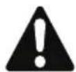
Jack Stand Nut Screw Front Wheel Level SurfaceTo Replace the Rear Wheels
NOTE: The rear wheel for zero turn mower is a driving wheel. When it is damaged, mower performance will be greatly affected. Replace it immediately.
- Restrain the movement of front wheels with wheel chocks.
- Lift the affected side of the mower with an automotive jack at the jack point shown in below image.
- Insert the jack stand underneath the mower's frame. Lower the automotive jack until the mower frame rests on the jack stand.
- Use the 19 mm socket wrench (not included) to loosen the four lug nuts (one turn for each nut).
- Remove the four lug nuts on the rear wheel. Check the four lug nuts and if they are in good condition, save them for reassembly. Otherwise, replace them at the same time.
- Pull the wheel off from the wheel studs. Replace the wheel.
- When securing the new wheel, ensure the proper orientation of the lug nuts – the tapered end against the wheel hub. Finger-tighten the lug nuts.
- Lower the mower by reversing the steps 2 & 3. Tighten the lug nuts in the order shown using a torque wrench. The recommended torque for the rear wheel lug nuts is 92-102Nm

WARNING: Particular attention must be given to tightening the wheel nuts, especially the drivewheel lug nut. Failure to correctly torque these items may result in the loss of a wheel, which can cause serious damage or personal injury.
NOTE: LUG NUTS ONLY - It is recommended that these be checked after the first 2 hours of operation, initially, every 100 hours and following removal for repair or replacement.

text_image
Frame Jack Point Jack Stand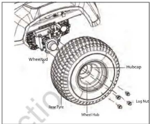
text_image
Wheeltud S Hubcap Rear Tyre Wheel Hub Lug Nut
text_image
Gradient Side Against the Wheel Hub 1 2 3 4Calibrating the Drive Tracking
If the mower is not tracking straight when both steering levers are pushed full forward, first check the air pressure in both rear wheel tyres. If the tyre pressures are set to the recommendation in section "CHECKING THE TYRE PRESSURE" in this manual, calibrate the mower tracking system as follows:
- Set the parking brake pedal in the braking position.
- Press the start/stop button briefly and the LCD screen will show the battery charge level.
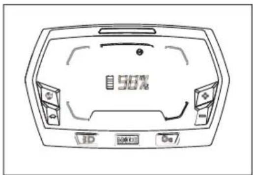
text_image
56%-
Press and hold the driving mode button and the calibration button " simultaneously for more than 3 seconds to enter the calibration interface. The LCD screen will show the calibration bar with two calibration indicators on both sides of the centre blank.
-
When the mower drives to the left, the right wheel speed of the mower should be calibrated; press the "MODE" button briefly to make the right calibration indicator flash. Then press the driving speed adjustment button "Press once, the calibration indicator will move to the right one grid from original position and continue to flash. This will decrease the right wheel speed. To increase the wheel speed, press the driving speed adjustment button "to move the indicator back."
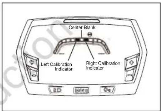
text_image
Center Blank Left Calibration Indicator Right Calibration Indicator 3D HODEB Do- When the mower drives to the right, the left wheel speed of the mower should be calibrated. Press the "MODE" button to set the left calibration indicator flash. Then press the driving speed adjustment button "Press once, the calibration indicator will move to the left one grid from original position and continues to flash. This will decrease the left wheel speed. To increase the wheels speed press the driving speed adjustment button "to move the indicator back.

text_image
Right Calibration Indicator, Move 1 Grid to Right Side- When the calibration is finished, press the driving mode button and the calibration button simultaneously for more than 3 seconds to save and quit the calibration interface.
Restart the mower and test if the mower is tracking straight. Otherwise, repeat the above steps until the mower is tracking straight.
Transporting the Mower
- Park the mower on a level surface.
- Raise the cutting deck to the highest position.
- Position and secure full width ramps to the trailer. Full width ramps will minimise the risk of the mower's wheels going off the side of the ramp.
- Slowly back the mower onto the ramp and into the trailer.
- Stop the mower and set the parking brake pedal.
- Turn off the start/stop button and remove the safety key.
- Secure the mower as needed, using straps or cables to prevent movement during transport.

natural_image
Line drawing of a person riding an electric tricycle on a ramp, with no visible text or symbols.Storing the Mower
• Fully charge the mower before storage.
NOTE: It is recommended to fully charge the mower at least once every 6 months.
- Remove the safety key from the mower.
- Thoroughly clean the mower. Refer to "Cleaning the Mower" above for complete instructions
- Inspect the mower for worn or damaged parts and tighten any nuts or screws that may have become loose.
- Store the mower in a dry, clean location. Do not store it next to corrosive materials, such as fertiliser or rock salt.
- Store the mower in a covered, enclosed space, out of the reach of children.
NOTE: Plastic coverings trap moisture around the mower, which causes rust and corrosion.
| PROBLEM CAUSE SOLUTION | |||
| LCD Display does not come on | Safety key not inserted• Fully insert safety key, press and hold the start/stop button down for at least 1 to 2 secondsBattery not charged• Insert charging plug and fully charge battery | ||
 | (Icon flashing) | The safety key is not inserted. | Insert the safety key then press and hold the start/stop button for 1 to 2 seconds to turn on the mower. |
 | (Icon flashing and alarm beeping) | Operator has left the seat without setting the parking brake | Set the parking brake pedal to the braking position |
| Mower won't drive: | |||
 | (Icon flashing) | The parking brake pedal is set on. | Check LCD screen for flashing Icons;Fully depress the parking brake pedal to release it from the braking position. |
 | (Icon flashing) | The operator is not sitting on the seat.Seat switch disengaged (operator left seat momentarily)The seat switch is not connected correctly. | The operator must be correctly sitting in the seat to operate the mower.Refer to Operator's Manual section "Installing the Seat"If the operator is seated on the seat and the icon is on, stop operating the mower immediately and check the seat connection. If the connection with the mower is confirmed correct, then please contact a Victa authorised service centre.The steering levers require a "reset". Return both steering levers to the open position and restart the mower. |
 | (Icon flashing) | The steering levers were not in the open position when mower was started. | |
| Mower stops driving when in use | |||
 | (Icon flashing) | Steering levers require a "reset". | Check LCD screen for flashing Icons;Return the steering levers to the open position and restart the mower. |
 | (Icon flashing) | Seat switch disengaged (operator left seat momentarily). | The operator must be correctly sitting in the seat to operate the mower. |
| The driving speed/driving mode cannot be adjusted. | For safety, these features cannot be adjusted while driving. | Stop mower and place steering levers in the open position, before adjusting driving mode. | |
Blades don't turn when the PTO switch is engaged. (Icon flashing) (Icon flashing) (Icon flashing)[ (Icon flashing)[ (Icon and Mower Status Indicator flashing) (Icon and Mower Status Indicator flashing) | The PTO switch was not pushed down when the mower was last stopped.Operator not sitting on the seatDeck is clogged with grass or obstruction and cutting motor is overloaded | Check LCD screen for flashing Icons;Push the PTO switch downward and then pull up to restart the mower's blades.The operator must be correctly sitting in the seat to operate the mower.Apply parking brake, turn off and remove safety key. Clear cutting deck of obstructions, allow mower to cool before restarting work | |
The blades stop working while cutting grass.[OVERLOAD](Icon and Mower Status Indicator flashing) (Icon and Mower Status Indicator flashing, alarm beeping) (Icon and Mower Status Indicator flashing, alarm beeping) | Battery level may be low. When battery level reaches approximately 20%, machine goes into limp home mode and mower blades will disen-gage automatically.The mower is over-loaded.The mower deck is clogged with grass and debris.The blades have hit a foreign object, resulting in motor self-protection.The mower is over-heated.The battery pack(s) in the mower's battery compartment is over-heated. | Drive directly to charging point and recharge batteryRaise cutting height if cutting long grassReduce ground speed if cutting long grassThe blades have hit a foreign object, resulting in motor self-protection.Clean the underside of the mower cutting deck. Refer to the "MAINTENANCE" section of this manual.Push the PTO switch downward to reset the blades. Turn off the mower and inspect for damage before restarting.Move mower to shaded area if possible. Shut the mower down and allow the mower to cool.Raise cutting height if cutting long grass.Reduce ground speed if cutting long grass.Avoid mowing in extreme heat. | |
| The alarm continues sounding. | The mower is in limp home mode.Parking brake is disengaged with no operator in the seat | Stop working and return to the battery charging area as soon as possible.Engage parking brake and remove safety key before leaving the mower. | |
| The mower cuts unevenly. • Tyre pressure is low and or uneven.• The blades are worn or bent.• Cutting deck is not level, damaged or worn. | • Check and correct tyre pressures.• Replace the cutting blades as instructed in the “MAINTENANCE” section of this manual.• Check the blade height and adjust cutting deck as required. Refer to “MAINTENANCE” section in this manual. | ||
| The mower does not mulch properly.There are clumps of grass trailing on the ground | • The grass is too long for effective mulching• The cutting height is too low• The ground speed is too fast• The grass is too wet for mulching• Wet grass clippings are sticking to the underside of the deck. | • Cut the grass twice, initially at a high setting and then again after it has dried at a lower setting.• Adjust the cutting height so a maximum of approximately 1/3 of the length of the leaf being cut.• Reduce ground speed.• Wait until the grass dries before mowing.• Clean the underside of the mower cutting deck. Refer to the “MANTENANCE” section of this manual. | |
There is excessive vibration. (Icon flashing and alarm beeping) (Icon flashing and alarm beeping) | • The cutting blades are loose.• The blades are worn unevenly or bent.• The mower deck nuts on the suspension linkage are loose.• The mower is set too low.• Operator left seat without applying parking brake with machine stopped on a slope. | Refer to the “MAINTENANCE” section of this manual.• Tighten the blade bolt to the recommended torque (67- 72 N.m.).• Replace BOTH cutting blades.• Check and tighten all nuts on the suspension linkages.• Raise the deck cutting height.• Apply parking brake.• Refer to the “SAFETY PRECAUTIONS” and “OPERATING INSTRUCTIONS” sections of this manual for mowing on a slope. The maximum recommended operating angle is 15 degrees. | |
| The mower is not tracking straight. | • The tyre pressures for the left and right wheels are different.• Drive motors require recalibration | • Check and adjust the air pressure in both rear wheel tyres as per the specification table on page 52 of this manual.• Refer to the “Calibrating the Drive Tracking” in the “MAINTENANCE” section of this manual. | |
| Parking brake not operating correctly | · Parking brake is worn or requires adjustment | · Contact a Victa authorised service centre for repair. | |
| The parking brake pedal will not release or is slow to spring back. | · Debris or dirt ingress inside the park-ing braking pedal mechanism. | · Contact a Victa authorised service centre for repair. | |
| The mower run time is short. | · Grass conditions, cutting height setting and drive speed will greatly affect the battery run time.· Worn blades · Sharpen or replace cutting blades | · Mow in dry conditions, raise the deck cutting height and slow down.· Fully discharge battery and fully recharge before use. | |
| The mower will not charge. · | · The charger plug is not correctly inserted into the charging port.· There is no power in the wall outlets.· The charger port on the mower is defective.· Charger malfunction.· Battery malfunction | · Reconnect the charger plug to see whether the mower can be charged normally. Be sure the plug and the charging port cover tab are fully connected.· Check operation with a different wall outlet· Contact a Victa authorised service centre for repair | |
| The charging time is long. · Charging time depends on the battery charge level at time of charge | · Refer to specification table on page 52 of this manual for estimated charging time.· Only use the genuine Victa charger supplied with the mower for charging. | ||
| The mower cannot be started after cleaning. | · Water ingress into electronic components | · Only clean the mower as per the instructions in the “MAINTENANCE” section of the Owner’s manual.· Do not use the mower in the rain.· If mower is accidentally left in rain, allow it to dry for 24 hours before use. | |
| The mower loses traction on a slope. | · The rear wheel tyres are worn.· Incorrect tyre pressure.· Mowing in wet conditions· Slope is excessive | · Contact a Victa authorised service centre for replacement.· Check and adjust the air pressure in both rear wheel tyres as per the specification table at the bottom of the Operator’s manual.· It is not recommended to mow in wet conditions.· Refer to the “SAFETY PRECAUTIONS” and “OPERATING INSTRUCTIONS” in this manual for mowing on a slope. The maximum recommended operating angle is 15 degrees. | |
| LCD Display | Fault Description | Error Code | Mower Status Indicator | Alarm Cause Solution | |
| OVERLOAD | The overload indicator flashing and the left drive motor stopped | E33 Solid red No The drive | motor is overloaded. | Reset the steering levers.Consider lower ground speed if grass is long or driving conditions are heavy. | |
| The overload indicator flashing and right drive motor stopped | E83 | ||||
| OVERLOAD | The overload indicator flashing and left blade motor has stopped | E43 Solid red No The blade | motor is overloaded. | Push the PTO switch downward and restart the mower's blades.Raise the deck cutting height or slow the driving speed to reduce the load of the mower. | |
| The overload indicator flashing and right blade motor has stopped | E93 | ||||
 | The overheat icon flashing and the blade motor and drive motor have stopped | E12 Solid red Beeps The mower | has over-heated. | Allow the mower to cool.Switch off and switch on the mower to cancel the error.Reduce the load of the mower by raising the deck cutting height or slowing down the driving speed. | |
| [YGZ] | The overheat icon flashing and the blade motor and drive motor have stopped | E13 Solid red Beeps Tempera- | ture sensor is faulty | Contact a Victa authorised service centre for repair. | |
| OVERLOAD | The LOW POWER icon flashing; drive and blade motors stopped | E11 Solid red Beeps Over | Discharge | Immediately return to charging station and charge battery. | |
 | PTO Switch icon flashing and left blade motor stopped | E41 - E46 | Solid red No The blade | motor was interrupted during operation or the PTO switch requires resetting. | Push the PTO switch downward and then pull up to restart the mower's blades. |
| PTO Switch icon flashing and right blade motor stopped | E41 - E96 | ||||
| See Fault Code | Hour meter does not change and the bat-tery display changes to 0% | E51 Solid red No PCBA com- | munication failure | Contact a Victa authorised service centre for repair. | |
| LCD Display | Fault Description Error Code | Mower Status Indicator | Alarm Cause Solution | ||
| See Fault Code | Left wheel driving motor does not rotate | PCBA controlling the left driving motor failure. | E31 Solid red No PCBA | Have repairs performed by a Victa authorised service centre. | |
| Plug (Six pins, signal wire) connecting the left drive motor to the corresponding PCBA is loose. | E36 Solid red No Loose | Have repairs performed by a Victa authorised service centre. | |||
| See Fault Code | Right wheel driving motor does not rotate | PCBA controlling the right driving motor failure. | E81 Solid red No PCBA | Have repairs performed by a Victa authorised service centre. | |
| Plug (Six pins, signal wire) connecting the right drive motor to the corresponding PCBA is loose. | E86 Solid red No Loose | Have repairs performed by a Victa authorised service centre. | |||
| See Fault Code | Left blade not rotating | PCBA Controlling the left blade motor failure. | E41 Solid red No PCBA | Have repairs performed by a Victa authorised service centre. | |
| Plug (Triple phase, power wire) connecting the left blade motor with the corresponding PCBA is loose. | E46 Solid red No Loose | Firstly check whether the blade is loose.Refer to the “MAINTE-NANCE” section in this Manual to tighten.Otherwise, have repairs performed by a Victa authorised service centre. | |||
| See Fault Code | Right blade not rotating | PCBA controlled right blade motor failure | E91 Solid red No PCBA | Have repairs performed by a Victa authorised service centre. | |
| Plug (Triple phase, power wire) connecting the right blade motor with the corresponding PCBA is loose. | E96 Solid red No Loose | Firstly check if the blade is loose. Refer to the “MAINTE-NANCE” section in this manual to tighten. Otherwise, have repairs performed by a Victa authorised service centre. | |||
 | Steering lever icon flashing | Left wheel drive motor not working | E32 Solid red No Over speed | Remove safety key and restart machine. If error persists contact your Victa authorised service centre. Possibly loose connector, connector failure, switch failure. | |
 | Steering lever icon flashing | Right wheel drive motor not working | E82 Solid red No Over speed | Remove safety key and restart machine. If error persists contact your Victa authorised service centre. Possibly loose connector, connector failure, switch failure. | |
| Voltage 56 V | ||
| Cutting Width 42in (1060mm) | ||
| Wheel Size | Front 11" x 4.00-5 | |
| Rear 18" x 8.50-8 | ||
| Cold Tyre Pressure | Front 22 PSI (151.6 kpa) | |
| Rear 18 PSI (124.1 kpa) | ||
| Turning Radius 0 | ||
| Blade Speed (RPM) Setting 2600, 2800, 3000, 3200 | ||
| Max. Driving Speed Settings | Forward 4.8 km/h, 8.1 km/h, 9.7 km/h, 11.3 km/h | |
| Reverse up to 4.8km/h | ||
| Charging | Charger | Input: 220-240 Vac 50Hz 7A |
| Output: DC59V - 15A | ||
| Charging Temp 5°C - 40°C | ||
| Nominal Cutting Height Adjustment(10 position) | 1.5" - 4.5" / 38 - 114mm | |
| Max.Towing Weight 113 kg | ||
| Operating Temperature 0°C – 40°C | ||
| Storage Temperature -20°C – 55°C | ||
| Weight (With battery pack) 255 kg | ||
©2024 Briggs & Stratton
Victa is a trademarks of Briggs & Stratton Australia Pty. Ltd.
ABN 13 006 576 856
All rights reserved. No part of this booklet may be reproduced by any means without prior written permission. All information herein is subject to change without notice.