HCA-4 - Smoke detector Hochiki - Free user manual and instructions
Find the device manual for free HCA-4 Hochiki in PDF.

User questions about HCA-4 Hochiki
0 question about this device. Answer the ones you know or ask your own.
Ask a new question about this device
Download the instructions for your Smoke detector in PDF format for free! Find your manual HCA-4 - Hochiki and take your electronic device back in hand. On this page are published all the documents necessary for the use of your device. HCA-4 by Hochiki.
USER MANUAL HCA-4 Hochiki
Conventional Fire Alarm System
(HCA-2, HCA-2D, HCA-4, HCA-4D, HCA-8, HCA-8D)
Installation and Operation Manual


Hochiki America Corporation
7051 Village Drive, Suite 100
Buena Park, CA90621-2268
714.522.2246 Corporate Headquarters
800.845.6692 Technical Support
http://www.hochiki.com
Version 2.09
Created: 12/18/2012
HA-06-266
Table of Contents
1. Introduction......5
1.1 Product Features....5
1.2 Electrical Specifications....6
1.3 Fire Alarm System Limitations....7
1.4 Installation Precautions....8
2. Controls and Indicators 10
2.1 Front Panel User Control Buttons.... 10
2.2 LED Indicators: 10
2.3 Local Piezoelectric (PZT) Sounder: 11
3. Control Panel Installation.... 12
3.1 Agency Requirements.... 12
3.2 Requirements for All Installations.... 12
3.3 Calculating Current Draw and Battery Size.... 13
3.3.1 Maximum Battery Standby Load 13
3.3.2 Calculating Maximum Current Draw & Battery Backup Requirements....13
3.4 Mounting the Enclosure 15
3.5 AC Power Connection 15
3.6 Battery Installation.... 16
3.7 NAC Output Circuit Installation 17
3.8 Zone Installation 18
3.9 Inner Door Label (Wiring Diagram) 19
3.10 Relay Outputs 20
3.11 DACT Phone Lines....21
3.12 Remote Annunciator (Model HCA-RA) 22
3.12.1 HCA-RA Installation 22
3.12.2 HCA-RA Specifications 23
3.13 Diagnostic LEDs 24
4. Control Panel Operations 25
4.1 LCD Display Screens 25
4.1.1 Initial Display Screen after System Initialization and Panel Revision 25
4.1.2 System Normal Status Screen 26
4.1.3 Off Normal System Status Screens and Sounds 26
4.1.4 Zone Alarm and/or Trouble Screens 26
4.1.5 System TROUBLE Screens 26
4.1.6 NAC Output Trouble Screens....27
4.1.7 Multiple Trouble Screens....27
4.1.8 Active Alarms and Trouble Screens 27
4.2 Operation Keys 28
4.2.1 System Reset 28
4.2.2 System Silence....28
4.2.3 System Acknowledge 28
4.3 Login Screen....28
4.3.1 Default Access Codes 28
4.4 User Top Level Menu Options....28
4.5 Installer Top Level Menu Options.... 29
4.6 Fire Drill 30
4.7 Date/Time Setup 30
4.8 Walk Test 31
4.9 Event History 31
4.9.1 Viewing Event History 31
4.9.2 Clearing Event History 32
4.10 Disabling Circuits 32
4.10.1 Disabling or Enabling Zones 32
4.10.2 Disabling or Enabling Outputs 33
4.11 Manual DACT test 33
4.12 Operating the Remote Annunciator 33
- Programming 34
5.1 Editing User and Installer Access Codes 34
5.2 Zone Programming Options.... 34
5.2.1 Zone Edit 34
5.2.2 Shorted Zone Mode....35
5.3 Output Circuits and Relay Programming 36
5.3.1 Reserved 36
5.3.2 NAC Output circuits....36
5.3.3 Relay Silencing Programming 38
5.3.4 Cadence Pattern Programming....38
5.4 Releasing Programming Options 39
5.4.1 Agent Releasing 39
5.4.2 Water Releasing....42
5.4.3 How to Install the Disconnect Switch on the Releasing Circuit....45
5.5 Remote Annunciator 47
5.6 DACT Setup 47
5.6.1 Enable/Disable the DACT 47
5.6.2 Auto Test Time of Day 47
5.6.3 Low AC Reporting Delay 48
5.6.4 Edit Accounts....48
5.6.5 Edit Phone Lines 51
5.7 Panel Factory Default Setup 52
5.7.1 Factory Default Settings 52
- DACT Reporting Codes and Compatible Receivers 53
6.1 DACT Reporting Codes for SIA and Contact ID 53
7. Compatible Devices for the HCA Series Panel 54
7.1 Compatible Conventional Initiating Devices.... 54
7.2 Compatible Releasing Devices 54
7.3 Compatible Heat Detector Cable 55
7.4 Compatible Notification Appliances.... 55
8. Warranty 56
1. Introduction
The HCA series fire alarm control panels provide all of the sophisticated features required of a leading edge conventional fire alarm system along with the simple operation and efficient installation methods demanded by both installers and building users.
The panel can be flush or surface mounted and the generously sized metal back box allows ample space for rear or top cable entries.
A comprehensive range of auxiliary devices is available to operate with the HCA series control panels including optical, ionization, photoelectric, photoelectric-thermal and heat detectors.
Each of the HCA series system components has been specifically designed to operate as part of the HCA series system. This provides assurance that the control panel, smoke detectors, interface devices and the ancillary components are all fully compatible with one another and that the full range of system functionality is supported by each device.
1.1 Product Features
The HCA panels have the following key features:
• 2, 4, or 8 conventional input zones (Models HCA-2, HCA2-D, HCA-4, HCA-4D, HCA-8, HCA-8D).
- Built-in Digital Alarm Communicator Transmitter (DACT) included with models HCA-2D, HCA-4D, HCA-8D.
• 4 notification appliance circuits (NAC) with built-in synchronization for ANSI 3.41 and Gentex.
- All 6 models come with a 6.5 amp power supply.
- Optional Remote Annunciator available – Model HCA-RA
- Agent and Water Releasing Support.
• Dedicated alarm and trouble relays.
- 3 programmable general purpose relays in addition to alarm and trouble.
• Built-in two line 32 character LCD display provides large easy to read text.
- 15 key keypad for panel operations and programming.
• Event History Buffer (255 events) with Date/Time stamp. Events can be displayed on LCD.
• Real time clock.
- Built-in walk test.
- Housed in a 14.6"W x 15.6"H x 4.53"D metal enclosure.
- Enclosure supports two 12V, 7Ah backup batteries.
1.2 Electrical Specifications
Table 1 - Electrical Specifications
| Primary AC 120VAC 50/60 Hz or 240VAC | 50/60 Hz |
| Power supply rating 6.5 Amps @ 24VDC (All Models) | |
| Maximum Battery Charging Current 0.98 Amps @ 22VDC | |
| Maximum Battery Charger Capacity 18 Ah battery (Two 7 Ah batteries fit inside cabinet) | |
| Initiating Device Circuits HCA-2 Alarm Zone 1 & 2 | |
| Initiating Device Circuits HCA-4 Alarm Zone 1, 2, 3, & 4 | |
| Initiating Device Circuits HCA-8 Alarm Zone 1, 2, 3, 4, 5, 6, 7, & 8 | |
| Initiating Wiring Style Class B (Style B and C) | |
| Normal Initiating Operating Voltage 23VDC, Maximum 25.5VDC, regulated | |
| Short Circuit Initiating Current (per zone) 48mA Maximum | |
| Maximum Initiating Resistance (per zone) 10 ohms | |
| Initiating End-of-Line Resistor 4.7K ohms 1/2W 5%, 0400-01820 | |
| Standby Detector Current (per zone) 4mA maximum | |
| Maximum Detector Count (per zone) 20 detectors | |
| Initiating Cabling Type 18AWG Twisted Shielded pair (14 – 18 AWG) | |
| Detector Base Impedance 430 ohms | |
| Notification Appliance Circuits | 4 NACs, Special Application |
| Maximum NAC Current Rating | 2.5 Amp maximum per circuit |
| Total NAC Signaling Current | 6.2 Amps total with 6.5 Amp supply |
| NAC Wiring Style | Class B (Style Y) |
| NAC Operating Voltage | 24VDC Nominal, 27VDC Maximum |
| NAC Line Impedance Maximum | 1.5 volt line drop maximum |
| NAC End-of-line Resistor | 10.0K ohms 1/2W 5%, 0400-01046 (0400-02590 for releasing application) |
| NAC Sync Protocols | Continuous On, Gentex, ANSI 3.41 Temporal, March |
| Trouble Relay rating | 3A & 30VDC, 1.0pf |
| Alarm Relay rating | 3A & 30VDC, 1.0pf |
| Relay 1 (programmable) | 3A & 30VDC, 1.0pf |
| Relay 2 (programmable) | 3A & 30VDC, 1.0pf |
| Relay 3 (programmable) | 3A & 30VDC, 1.0pf |
1.3 Fire Alarm System Limitations
An automatic fire alarm system – in general is made up of smoke detectors, heat detectors, manual pull stations, call points, audible warning devices, and fire alarm control panels with remote notification capability, which can supply early warning of a developing fire. Such a system, on the other hand, is unable to assure protection against property damage or loss of life resulting from a fire.
The manufacturer recommends that smoke and /or heat detectors must be positioned throughout a protected premise following the recommendations of the current edition of the National Fire Protection Association Standard 72 (NFPA 72), manufacturer's recommendations contained in the Guide for proper Use of System Smoke Detectors, which is made available at no charge to all installing dealers. A study by the Federal Emergency Management Agency (an agency of the United States government) indicated that smoke detectors may not go off in as many as 35% of all fires. A fire alarm system may not provide timely or sufficient notice, or might not function, for a diversity of reasons:
Smoke detectors may not sense fire where smoke cannot reach the detectors such as in chimneys, in or behind walls, on roofs, or on the other side of closed doors. Smoke detectors also may not sense a fire on another level or floor of a building. A second-floor detector, for example, may not sense a first-floor or basement fire.
Particles or combustion or “smoke” from a developing fire may not reach the sensing chambers of smoke detectors because:
- Barriers such as closed or partially closed doors, walls, or chimneys may inhibit particle or smoke flow.
- Smoke particles may become "cold," stratify, and not reach the ceiling or upper walls where detectors are located.
- Smoke particles may be blown away from detectors by air outlets.
- Smoke particles may be drawn into air returns before reaching the detector.
The amount of “smoke” present may be insufficient to alarm the smoke detectors. Smoke detectors are designed to alarm at various levels of smoke density. If such density levels are not created by a developing fire at the location of detectors, the detectors will not go into alarm. Smoke detectors, even when working properly, have sensing limitations. Detectors that have photo electronic sensing chambers tend to detect smoldering fires better than flaming fires, which have little visible smoke. Detectors that have ionizing-type sensing chambers tend to detect fast-flaming fires better than smoldering fires. Because fires develop in different ways and are often unpredictable in their growth, both types of detectors are necessarily best and a given type of detector may not provide adequate warning of a fire. A smoke detector cannot be expected to provide adequate warning of fires caused by arson, children playing with matches (especially in bedrooms), smoking in bed, and violent explosions (caused by escaping gas, improper storage of flammable materials, etc.). Heat detectors do not sense particles or combustion and alarm only when heat on their sensors increases at a preset rate or reaches a predetermined level. Rate-of-rise heat detectors may be subject to reduced sensitivity overtime. For this reason, the rate-of-rise feature of each detector should be tested at least once per year by a qualified fire protection expert. Heat detectors are designed to protect property, not life.
IMPORTANT! Smoke detectors must be installed in the same room as the control panel and in rooms used by the system for the connection of alarm transmission wiring, communications, signaling, and/or power. If detectors are not located near the control panel, a developing fire may damage the alarm system, crippling its ability to report a fire.
Audible warning devices such as bells may not alert people if these devices are located on the other side of closed or partly open doors or are located on another floor of a building. Any warning device may fail to alert people with a disability or those who have recently consumed drugs, alcohol or medication. Please note that:
- Strobes can, under certain circumstances, cause seizures in people with conditions such as epilepsy.
Studies have shown that certain people, even when they hear a fire alarm signal, do not respond or comprehend the meaning of the signal. It is the property owner's responsibility to conduct fire drills and other training exercise to make people aware of fire alarm signals and instruct them on the proper reaction to alarm signals.
In rare instances, the sounding of a warning device can cause temporary or permanent hearing loss.
A fire alarm system will not operate without any electrical power. If AC power fails, the system will operate from standby batteries only for a specified time and only if the batteries have been properly maintained and replaced regularly.
Equipment used in the system may not be technically compatible with the control. It is essential to use only equipment listed for service with your control panel.
Telephone lines needed to transmit alarm signals from a premise to a central monitoring station may be out of service or temporarily disabled. For added protection against telephone line failure, backup radio transmission systems are recommended.
The most common cause of fire alarm malfunction is insufficient maintenance. To keep the entire fire alarm system in excellent working order, on-going maintenance as required by the manufacturer's recommendations, UL and NFPA 72 shall be followed. Environments with large amounts of dust, dirt or high air velocity require more frequent maintenance. A maintenance agreement should be arranged through the local manufacturer's representative. Maintenance should be scheduled monthly or as required by National and/or local fire codes and should be performed by authorized professional fire alarm installers only. Adequate written records of all inspection should be kept.
1.4 Installation Precautions
WARNING – Several different sources of power can be connected to the fire alarm control panel. Disconnect all sources of power before servicing the control unit. Associated equipment may be damaged by removing and/or inserting cards, modules or interconnecting cables while the unit is energized. Do not attempt to install, service, or operate this unit until this manual is read and understood fully.
CAUTION – System Reacceptance Testing Requirements. To ensure proper system operation, this product must be tested in accordance with NFPA 72 after any programming operation or change in site specific software. Re-acceptance testing is required after any change, addition or deletion of system components, or after any modification, repair or adjustment to system hardware or wiring. All components, circuits, system operations, or software functions known to be affected by a change must be 100% tested. In addition, to ensure that other operations are not inadvertently affected, at least 10% of initiating devices that are not directly affected by the change, up to a maximum of 50 devices, must also be tested and proper system operation verified.
This system meets NFPA requirements for indoor dry operation at 0-49°C/32-120°F and at a relative humidity up to 93 ±2%RH (non-condensing) at 32 ±2°C/90 ±3°F. However, the useful life of the system's standby batteries and the electronic components may be adversely affected by extreme temperature ranges and humidity. Therefore, it is recommended that this system and all peripherals be installed in an environment with a nominal room temperature of 15-27°C/60-80°F.
Verify that wire sizes are adequate for all initiating and indicating device loops. Refer to the manual specifications section for maximum allowable I.R. drop from the specified device voltage.
Like all solid state electronic devices, this system may operate erratically or can be damaged when subjected to lightning-induced transients. Although no system is completely immune from lightning transients and interferences, proper grounding will reduce susceptibility. Overhead or outside aerial wiring is not recommended, due to an increased susceptibility to nearby lightning strikes. Consult with the Technical Services Department if any problems are anticipated or encountered.
Disconnect AC power and batteries prior to removing or inserting circuit boards. Failure to do so can damage circuits.
Make all cable entries from the sides or top of the enclosure using the knockouts provided. Route internal wiring around the outer edges of the enclosure, and verify that it will not interfere with battery, transformer, or printed circuit board locations and connections.
Do not tighten screw terminals more than 9 in-lbs. Over-tightening may damage threads, resulting in reduced terminal contact pressure and difficulty with screw terminal removal.
This system contains static-sensitive components. Always ground yourself with a proper wrist strap before handling any circuits so that static charges are removed from the body. Use static-suppressive packaging to protect electronic assemblies removed from the unit.
Follow the instructions in the installation, operating, and programming manuals. These instructions must be followed to avoid damage to the control panel and associated equipment. FACP operation and reliability depend upon proper installation by authorized personnel.
2. Controls and Indicators
2.1 Front Panel User Control Buttons
Acknowledge
This function, abbreviated "Ack" on the keypad, is used to acknowledge an off normal condition such as an alarm or trouble condition. The acknowledge function tells the panel that building personnel or emergency responders are aware of the alarm, trouble, or supervisory condition. Acknowledging the alarm or trouble condition also silences the panel's sounder (PZT).
Alarm Silence
This function, abbreviated "Silence" on the keypad, is also known as "audible silence". Depending on the configuration of the alarm system, this function will either silence the system's notification appliances completely, or will silence only the audible alarm, with strobe lights continuing to flash. Audible silence allows for easier communication amongst emergency responders while responding to an alarm while still leaving the visual appliances on to indicate there is still an active alarm.
Reset
This function will reset the panel after an alarm condition. All initiating devices are reset, and the panel is cleared of any alarm conditions. If an initiating device is still in alarm after the system is reset, such as a smoke detector continuing to sense smoke, or a manual pull station still in an activated position, another alarm will be initiated.
2.2 LED Indicators:
AC Power Green LED
When this indicator is lit, power is being provided to the system from the building's electrical system and not from the backup battery. When the AC power condition is low or completely gone, the trouble indicator comes on and the AC power indicator goes off. If the AC power indicator is lit without any other indicators also lit, then the system is in a normal standby condition. If no LEDs are lit, there is no power source feeding the panel.
Alarm Red LED
This Indicator is lit when an alarm condition exists in the system, initiated by smoke detectors, heat detectors, sprinkler flow switches, manual pull stations, manual call points, or other initiating devices. Along with the indicator on the panel, notification appliances such as horns and strobes are also activated, signaling a need to evacuate the building occupants. In an alarm condition, the fire alarm control panel indicates where the alarm originated. The alarm panel can be reset once the device which initiated the alarm is reset, such as returning the handle of a manual pull station to its normal position.
Trouble Yellow LED
When on steady or flashing, it means that a trouble condition exists on the panel. Trouble conditions are often activated by a contaminated smoke detector or an electrical problem within the system. Trouble conditions are also activated by a zone being disabled (disconnected from the system), low power on the backup battery, disabled notification appliance circuits, earth ground faults, shorted circuits or open circuits. The alarm panel's sounder will activate if a trouble condition exists. In a trouble condition, the panel displays the zone or devices causing the trouble condition. The trouble indicator goes out automatically when the situation causing the trouble condition is rectified or restores to normal.
Silence Yellow LED
The silence signal indicates that a trouble, supervisory or and/or alarm condition has been silenced by activating the silence key.
Supervisory Yellow LED
The supervisory signal indicates that a portion of the building's fire protection system has been disabled (such as a fire sprinkler control valve being closed and, consequently, a sprinkler tamper switch being
activated), or, less frequently, that a lower priority initiating device has been triggered (such as a duct smoke detector). The "Supervisory" indicator requires a "Reset" to clear.
2.3 Local Piezoelectric (PZT) Sounder:
The piezoelectric sounder provides separate and distinct sounds for alarm, trouble, and supervisory conditions. The PZT sounds are as follows:
- Alarm – On for 1.25 seconds, Off for 0.25 seconds, repeat.
- Supervisory – On for 0.75 seconds, Off for 0.75 seconds, repeat.
- Trouble – On for 0.4 seconds, Off for 0.4 seconds, repeat.
3. Control Panel Installation
Important, please read before proceeding!
The equipment described in this manual is listed by ETL TESTING LABORATORIES for use in fire alarm signaling systems, only when installed in accordance with this manual and the latest National Fire Protection Association Standards NFPA 72; the National Electrical Code (NFPA 70); the Life Safety Code (NFPA 101); and/or the local authority having jurisdiction (AHJ). It is possible to apply system components incorrectly or arrange system components and installation wiring so that required life safety functions are NOT performed. As a result, lives may be lost.
To minimize this possibility:
√ DO NOT deviate from any installation instructions contained in this manual.
√ DO NOT assume any installation details not shown in this manual.
√ DO NOT alter any mechanical or electrical features of the equipment supplied
BE FAMILIAR with the building code, fire prevention code, and/or requirements of the Authority Having Jurisdiction (AHJ) in the locale of the installation.
!Caution!
Under normal and fault conditions, AC line voltages may be present on any terminal. Touching any component could be hazardous and result in loss of life. A short circuit can result in arcing that could cause molten metal injuries to testing personal. To minimize this possibility, only qualified electrical technicians familiar with electrical hazards should perform these checkout procedures. Safety glasses should be worn by such personnel, and instruments used for voltage measurement should be designed for the purpose and should be in good mechanical and working order.
If there is application or installation information that is not clear or not covered in this manual, please contact us at: Hochiki America Corp. Technical Support, 1-800-845-6692 or by email: technicalsupport@hochiki.com
3.1 Agency Requirements
The PANEL is listed by ETL TESTING LABORATORIES to UL 864 9 ^th edition as a FACP control unit for use in NFPA 72 systems.
3.2 Requirements for All Installations
General requirements are described in this section. When installing an individual device, refer to the specific section of the manual for additional requirements.
• All field wiring must be installed in accordance with NFPA 70 National Electric Code.
- Use UL listed smoke detectors and notification appliances compatible with the PANEL from those specified in Section 7 of this manual.
- A full system checkout must be performed every time the panel is programmed.
The HCA series of conventional fire alarm control panels are designed in accordance UL864 9 ^th Edition, Control Units and Accessories for Fire Alarm Systems.
3.3 Calculating Current Draw and Battery Size
Use this section to determine the current draw and standby battery needs for your installation.
3.3.1 Maximum Battery Standby Load
The nominal battery capacity versus system standby current is shown in table 3.3.1 for typical battery sizes. Make sure that the standby battery calculation of table 3.3.2 is less than the number of table 3.3.1 for the battery chosen and the standby hours needed.
Table 3.3.1
| Battery Size Maximum standby load with 5 minutes alarm, 24 hour standby | Maximum standby load with 5 minutes alarm, 60 hour standby | ||
| 7AH | 269mA | * | |
| 12AH | 477mA | 191mA | |
| 18AH | 727mA | 291mA | |
* 7AH size is not capable of 60 hour standby.
3.3.2 Calculating Maximum Current Draw & Battery Backup Requirements
Use table 3.3.2 to assist you in determining the worst case battery backup amp-hour requirements for the particular installation.
1) The known standby and alarm current draws for the panel are already filled in for table 3.3.2. Note that all EOL resistor currents for the zones and output circuits are already accounted for in the main panel current draw numbers and should not be included in the zone or output circuit currents.
2) Add in the total smoke detector standby current draw for each zone that is used and all standby accessory loads on output circuits configured as auxiliary power constant or auxiliary power resettable. Note that auxiliary power door holder current is not included for battery standby because it is powered down during battery backup. Put the appropriate current draw per device in the standby and alarm current boxes and record the total number of devices per zone or circuit in the "number of devices" column.
3) Add in all notification appliance alarm current draws for each output circuit configured as NAC.
4) Add up the total standby and alarm current draw values and record the totals in the appropriate boxes of table 3.3.2.
5) Multiply the standby and alarm currents with the standby and alarm hours to determine the total amp-hours needed for both standby and alarm. Add up the standby and alarm amp-hour results to get the total battery backup amp-hours required. Select a battery size that is at least 120% of the total amp-hours required to achieve a 20% safety margin for the battery backup.
6) Make sure the total standby and alarm current you calculated (including the current for the panel itself) does not exceed the 6.5 amps power supply rating. Also make sure you have not exceeded the maximum current per output circuit.
Table 3.3.2 Worst Case Battery Current Calculations
| Devices Number of Devices Current per device Standby | Current | Alarm Current | ||
| Multiply This Column By This Column To Get Standby/Alarm Currents | ||||
| Main Panel | ||||
| HCA Panel 1 Standby: 0.160A 0.160A | ||||
| Alarm: 0.290A | 0.290A | |||
| Panel Relays | ||||
| Alarm relay 1 Standb | y: 0.0A | 0.0A | ||
| Alarm: 0.025A | 0.025A | |||
| Trouble relay 1 (trouble relay OFF due to loss of AC) | Standby: 0.0A | 0.0A | ||
| Alarm: 0.0A | 0.0A | |||
| Relay 1 | Standby: 0.0A | 0.0A | ||
| Alarm: 0.025A | ||||
| Relay 2 | Standby: 0.0A | 0.0A | ||
| Alarm: 0.025A | ||||
| Relay 3 | Standby: 0.0A | 0.0A | ||
| Alarm: 0.025A | ||||
| Remote Annunciator | ||||
| Number of Remote Annunciators | (maximum 1) | Standby: 0.012A | ||
| Max Alarm: 0.030A | ||||
| Zones | ||||
| Number of Zone 1 Detectors | Standby: | |||
| Max Alarm: 0.040A | ||||
| Number of Zone 2 Detectors | Standby: | |||
| Max Alarm: 0.040A | ||||
| Number of Zone 3 Detectors | Standby: | |||
| Max Alarm: 0.040A | ||||
| Number of Zone 4 Detectors | Standby: | |||
| Max Alarm: 0.040A | ||||
| Number of Zone 5 Detectors | Standby: | |||
| Max Alarm: 0.040A | ||||
| Number of Zone 6 Detectors | Standby: | |||
| Max Alarm: 0.040A | ||||
| Number of Zone 7 Detectors | Standby: | |||
| Max Alarm: 0.040A | ||||
| Number of Zone 8 Detectors | Standby: | |||
| Max Alarm: 0.040A | ||||
| Notification Appliances or Auxiliary Power Devices | ||||
| Output 1 | Standby: | |||
| Alarm: | ||||
| Output 2 | Standby: | |||
| Alarm: | ||||
| Output 3 | Standby: | |||
| Alarm: | ||||
| Output 4 | Standby: | |||
| Alarm: | ||||
| Total Worst Case Standby Current | A | |||
| Total Worst Case Alarm Current | A | |||
| Number of Standby hours required (typically 24 hours) | H | |||
| Number of Alarm hours required (5 minutes is 0.0833 hours) | H | |||
| Number of Standby amp-hours (standby amps X standby hours) | AH | |||
| Number of Alarm amp-hours (alarm amps X alarm hours) | AH | |||
| Total battery amp hours required (add standby and alarm AHs) | AH | |||
3.4 Mounting the Enclosure
Install the enclosure as follows:
- Carefully unpack the system components and inspect for any damage due to shipping.
- Mount the enclosure in a clean, dry, vibration-free area where extreme temperatures are not encountered. The location should be readily accessible with sufficient room for easy installation and maintenance.
- Mount the cabinet by using the two mounting holes located in the upper back of the cabinet. After the panel has been properly located using the mounting holes, the panel can be secured.
- Complete all conduit connections to the cabinet. Use the knockouts provided in the top and the sides.
Wire must NOT enter the bottom of the cabinet, since this area is intended for batteries only.
3.5 AC Power Connection
WARNING!
To reduce the risk of electrical shock, make sure that all power has been turned off or disconnected prior to attempting to connect AC power to the Power Supply.
Apply the AC Power BEFORE connecting the batteries to the Panel!
Provide the Fire Alarm Control Panel with a dedicated AC Circuit rated 15 Amps or higher. Refer to figure 3.5 for the AC power wiring diagram.
- Route the power cable into the cabinet via a left side knock out hole.
- Attach the AC source live (hot) wire from the source to the terminal labeled "L".
- Attach the AC source neutral wire from the source to the terminal labeled "N" terminal.
- Attach the AC ground wire from the source to the terminal labeled 12
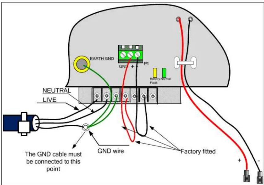
Figure 3.5 - AC Power Wiring Connection
3.6 Battery Installation
The batteries are placed at the bottom of the enclosure. The HCA panel is fully protected if the batteries are connected in the wrong polarity. The Amber battery fault LED on the main circuit board will show steady in such a condition. When the green battery LED is on steady it shows that the battery condition and connections are normal. See Figure 3.6 below.
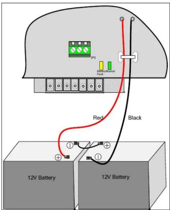
Figure 3.6 - Battery Connection to the HCA Control Panel
3.7 NAC Output Circuit Installation
The HCA series control panel has 4 built-in output circuits which can be individually configured as either class B (style Y) supervised notification appliance circuits (NACs), auxiliary power 24VDC circuits, auxiliary power 24V resettable circuits or auxiliary power 24V door holder circuits.
Figure 3.7 shows output circuit 1 wired as a class B NAC output. Observe the polarity of the wiring and the placement of the 10kΩ end of line (EOL) resistor located at the very end of the class B wiring. To wire an output as an auxiliary power circuit, observe the same polarity as shown in figure 3.7, but it is not a requirement to include the EOL resistor.
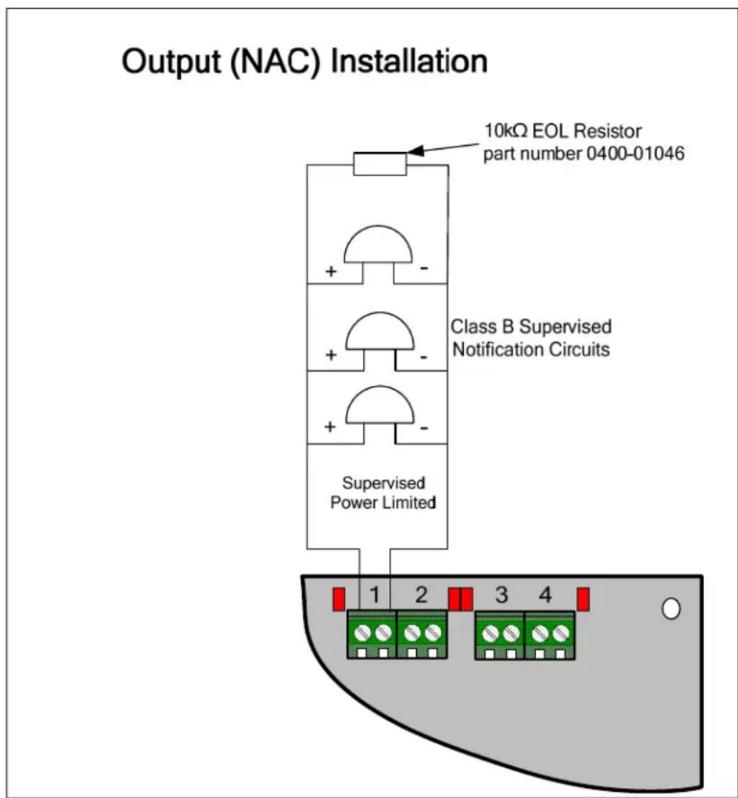
Figure 3.7- Supervised Notification Appliance Wiring
3.8 Zone Installation
The HCA series panel has either 2, 4 or 8 class B (style B or C) conventional input zones depending on the HCA model chosen. The mode programming option determines if the zone logic interprets short circuits as an alarm (style B) or a trouble condition (style C). Wire the smoke detector positive terminals to the HCA terminal labeled “+” and the negative smoke detector terminals to the HCA terminal labeled “-” as shown in figure 3.8 which shows the HCA-8 panel. Each active zone requires a 4.7kΩ end of line (EOL) resistor at the very end of the zone as shown in figure 3.8.
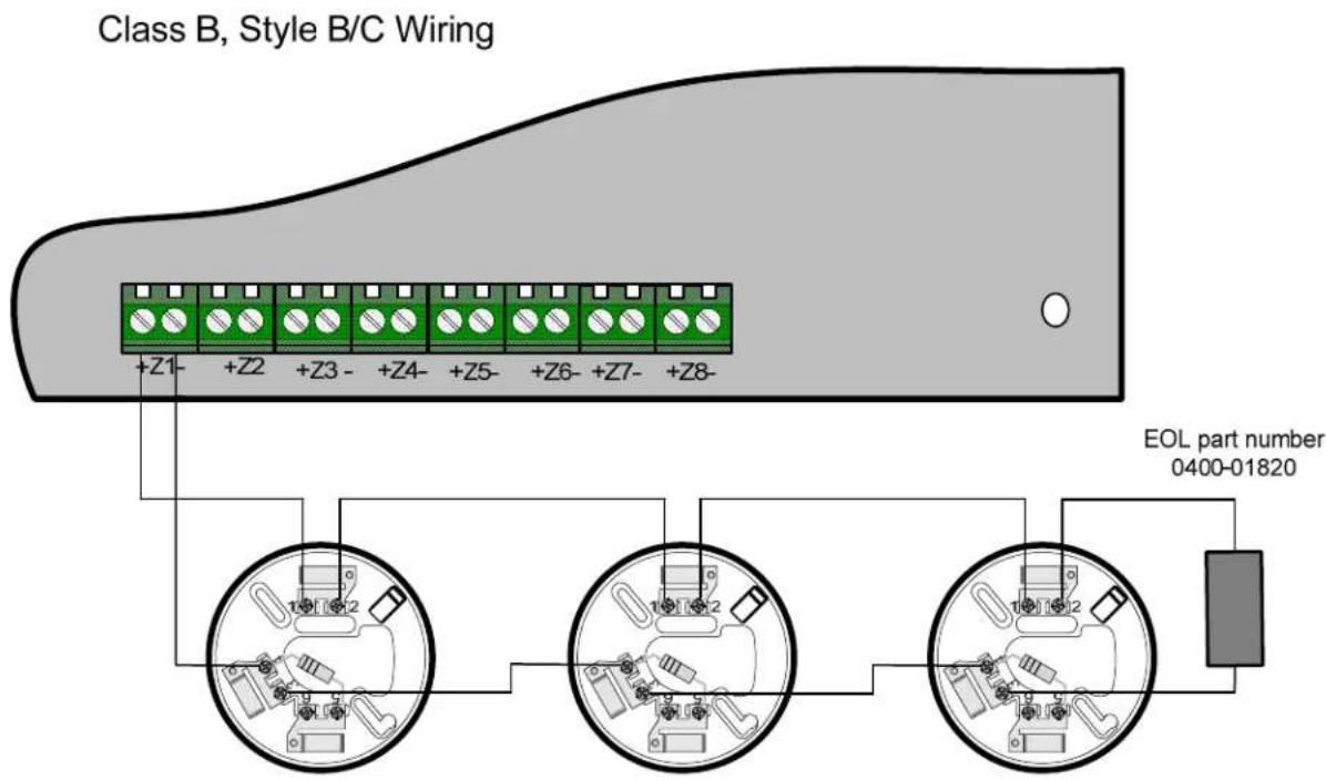
Figure 3.8 Zone Installation
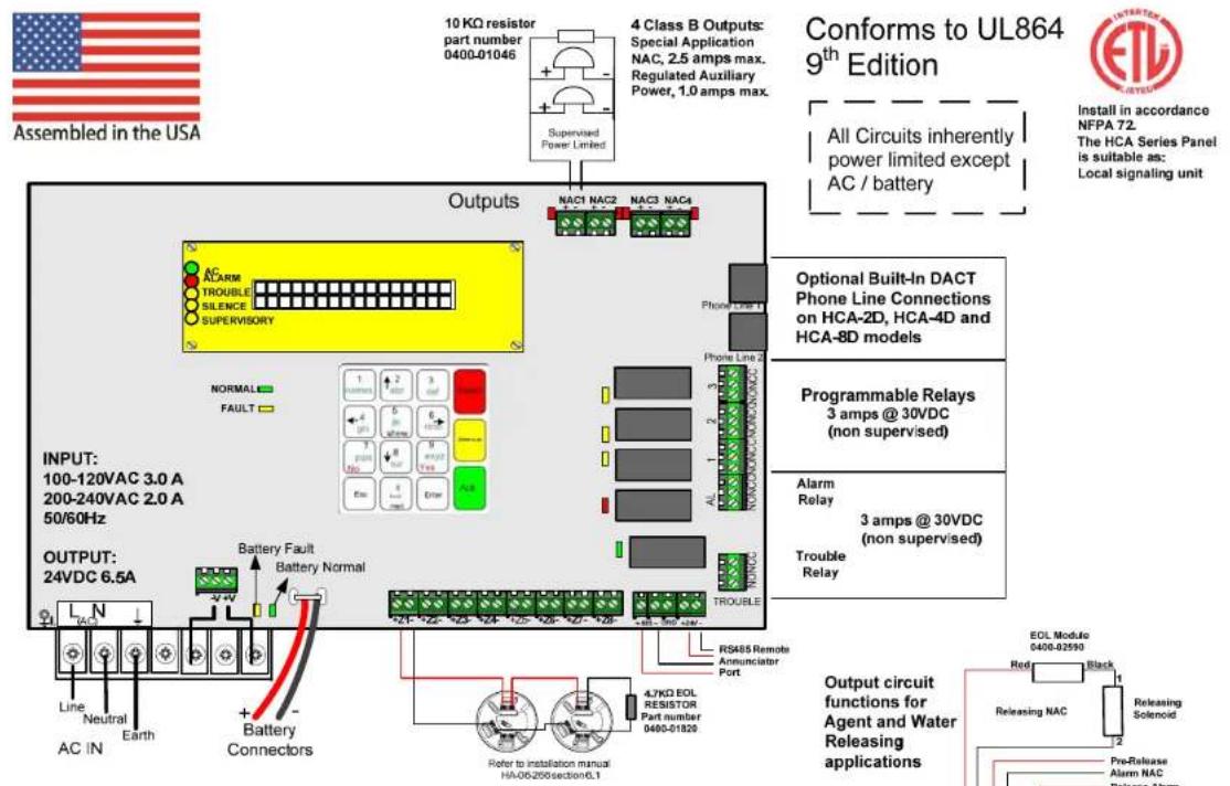
3.9 Inner Door Label (Wiring Diagram)
Compatibility identifier number: 0409007
Software release: Version 2.XX
Indoor use only (dry)
Commercial - protected-premises control unit
HCA SERIES WIRING DIAGRAM
P/N 1700-05660 Doc. HA-03-343 Rev. V2.XX DATE mm/dd/yyyy
Conforms to UL864 ^9^th Edition

Install in accordance NFPA 72
The HCA Series Pane is suitable as:
Local signaling unit
All Circuits inherently power limited except AC / battery
Optional Built-In DACT Phone Line Connections on HCA-2D, HCA-4D and HCA-8D models
Programmable Relays 3 amps @ 30VDC (non supervised)
Alarm Relay
3 amps @ 30VDC (non supervised)
Trouble Relay
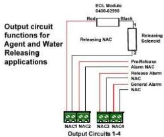
flowchart
graph TD
    A["EDL Module 0400-82593"] --> B["Releasing NAC"]
    B --> C["Releasing Solenoid"]
    C --> D["Pre-Release Alarm NAC"]
    C --> E["Release Alarm NAC"]
    C --> F["General Alarm NAC"]
    A --> G["NAC1 NAC2"]
    A --> H["NAC3 NAC4"]
    G --> I["Output Circuits 1-4"]
    H --> I
    I --> J["Red"]
    I --> K["Black"]
3.10 Relay Outputs
Each HCA series panel has 5, form C relays. 2 of the relays are dedicated to common alarm and common trouble functions. The other 3 relays can be configured as Alarm or Supervisory functions. All 5 relay outputs (Alarm, Trouble, and the programmable relays) carry the same voltage and current ratings. The relays are rated 3 amps at 30VDC, power factor 0.4 - 1.0.
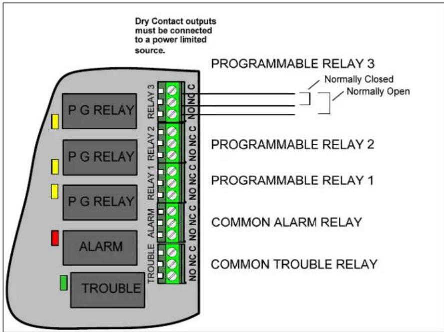
Figure 3.10- HCA Relay Outputs
3.11 DACT Phone Lines
Models HCA-2D, HCA-4D and HCA-8D have a built-in Digital Alarm Communicator Transmitter (DACT). These models have 2, RJ-45 phone line connectors used to wire the incoming telephone lines and pass through any local premises phone connections that are shared with the DACT. See figure 3.11 for wiring details.
IMPORTANT: The HCA DACT must be the first device connected on the incoming telephone lines and all local premises phones must be located on the phone wiring identified as Phone Ring and Phone Tip in the diagram below. Only direct connections to the Telco should be wired to the Telco Ring and Telco Tip in order for the DACT to be able to properly seize control of the telephone line when it needs to report.
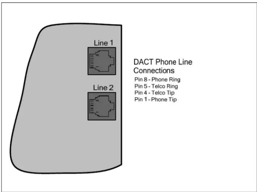
Figure 3.11–RJ-45 Phone Line Connectors
3.12 Remote Annunciator (Model HCA-RA)
3.12.1 HCA-RA Installation
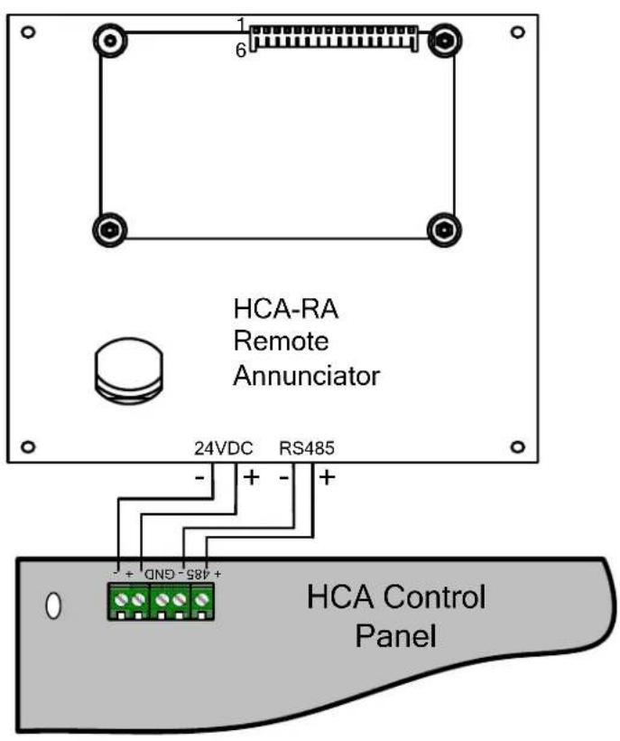
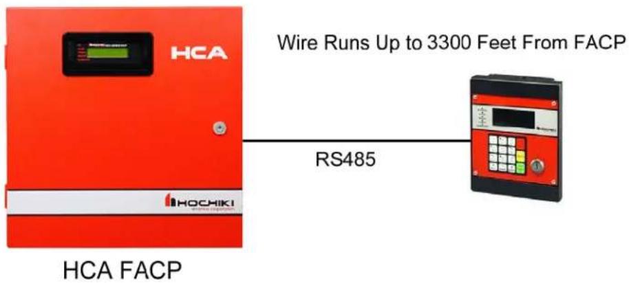
Figure 3.12 HCA-RA connections to the HCA panel.
It is necessary to enable the remote annunciator in the panel programming in order for the annunciator to function as intended. See programming section 5.5 of this manual for instructions on adding a remote annunciator to the HCA panel.
3.12.2 HCA-RA Specifications
Electrical Specifications
Operating Voltage: 16-26 VDC
Standby Current: 12 mA max
Alarm Current: 30 mA
Wiring Distance: 3,300ft max from FACP (using 18 gauge or larger diameter wire)
Maximum Annunciators Per System: 1
Environmental Specifications
Operating Temperature: 32°F -120°F (0°C - 49°C)
Humidity: 10% – 93% non-condensing
Approvals
ETL Listed
Compatibility
Compatible with HCA series fire alarm panels.
Physical Dimensions
160mm x 160mm x 44 mm (6.3in x 6.3in x 1.75in)
Features
- 64-character backlit LCD display (4 lines with 16 characters on each line)
- Membrane Keypad
- Accepts user codes or fire fighter's key
- Larger keypad buttons for system reset and silence
• RS-485 interface to panel
- On-board Piezo sounder audibly indicates alarms, troubles,
and supervisories.
- Five status LEDs for alarm, supervisory, trouble, silence and AC power conditions
• Wiring lengths up to 3300 ft. from the FACP
• ETL listed, complies with NFPA 72
3.13 Diagnostic LEDs
The HCA panel contains various diagnostic LEDs that may be helpful when troubleshooting. Please refer to Figure 3.13 and the table below.
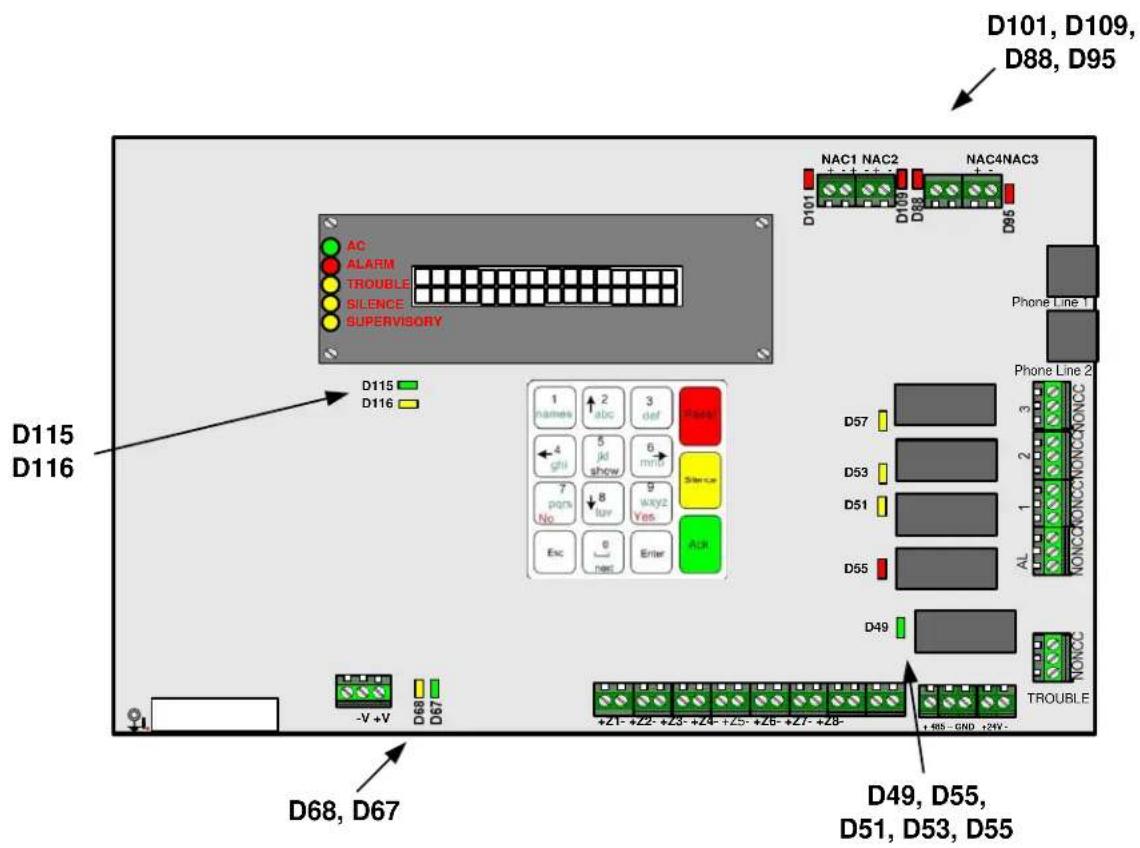
Figure 3.13 HCA Diagnostic LED Locations
| Designation Color Description | ||
| D115 Green | This LED | flickers when the panel is working normally. |
| D116 | Amber | When this LED is lit, it indicates trouble with the panel's internal operation.Contact Hochiki Technical Support for assistance. |
| D67 | Green | This LED is lit when the standby batteries are properly connected. |
| D68 | Amber | This LED is lit if the standby battery polarity is reversed. |
| D101, D109, D88, D95 | Red | These LEDs indicate the On/Off state of each of the four NACs. |
| D49 | Green | This LED is lit when the Trouble is activated. Note that the trouble relay is activated when the panel is normal and there are no troubles present. |
| D55 | Red | This LED is lit when the Alarm relay is activated. |
| D51, D53, D57 | Amber | These LEDs are lit when the corresponding programmable relays are activated. |
4. Control Panel Operations
All non-programming operations and system behaviors are described in this section. See section 5 for initial setup and control panel programming.
The HCA series control panel has 15 keys as shown in the diagram below that are used to operate and program the panel. Some of the keys have additional functions, which become active depending on the menu screen being displayed at the time.
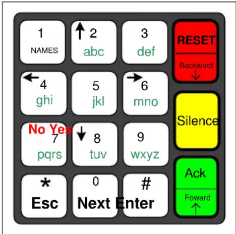
Figure 4 - HCA Control Panel Keypad
Important Note: If the system is left idle in a menu without any activity for 2 minutes, the system will reset itself.
4.1 LCD Display Screens
All status and operations display screens for the HCA panel are described below.
4.1.1 Initial Display Screen after System Initialization and Panel Revision
The HCA control panel will only take a few seconds to initialize after the system is powered on. The first screen to be displayed will be the panel software revision which is displayed for about 10 seconds before the panel will display the system status idle screen. The software revision can also be displayed at any time by pressing the ACK key twice when the panel is idle. Pressing the ESC key with the software revision screen active will bring the panel back to the system status idle screen.
Ver X.YY Date: 12/06/2012
The X is the version number and the YY is the revision number.
4.1.2 System Normal Status Screen
When the control panel condition is normal standby (no active alarms, troubles, etc.), it displays one of two system normal screens:
16/03 13:17:03 SYSTEM NORMAL
European time and date format
03/16 01:17:03pm SYSTEM NORMAL
American time and date format
4.1.3 Off Normal System Status Screens and Sounds
During off normal alarm, trouble, or supervisory conditions, the piezoelectric sounder provides separate and distinct sounds as follows:
- Alarm – On for 1.25 seconds, Off for 0.25 seconds, repeat.
- Supervisory – On for 0.75 seconds, Off for 0.75 seconds, repeat.
- Trouble – On for 0.4 seconds, Off for 0.4 seconds, repeat.
When alarms, supervisory and troubles are active at the same time, the alarm pattern is the highest priority, followed by supervisory and then trouble.
4.1.4 Zone Alarm and/or Trouble Screens
The screen below is displayed when at least one zone is in trouble or alarm.
Z1 2 3 4 5 6 7 8 N A T N S D N A
This screen is activated whenever an off normal condition exists for one or more zones. For any zone in alarm, the zone status letter will blink on and off.
The possible symbols appearing on the bottom line are:
N zone enabled and operating correctly (normal standby)
D zone disabled
T zone enabled and in trouble condition
S zone in supervisory condition
A zone in non-release alarm condition
P zone in pre-release alarm condition
R zone in release alarm condition
B indicates an Abort (Bypass) condition during an active release sequence countdown
4.1.5 System TROUBLE Screens
The screens below are displayed during the following system trouble conditions:
NO BATTERY
This screen is displayed when there is no battery connected.
LOW BATTERY
This screen is displayed when the battery is not fully charged.
| CHARGER FAULT | This screen is displayed when the battery charger is not operating properly. |
| AC FAULT | This screen is displayed when there is no AC power or the AC power is low. |
| GROUND FAULT | This screen is displayed when there is an earth ground fault between at least one control panel circuit and earth ground. |
| Remote Panel err | This screen is displayed when there is a problem communicating to the remote annunciator and the panel has been configured with the remote annunciator. |
| Account # Trbl | This screen is displayed if the DACT fails to communicate to the central station. The account that failed will be indicated by a number, 1 – 4. |
| Phone Line # Trb | This screen is displayed when one of the telephone lines have failed. The line that failed will be indicated by a number, 1 or 2. |
4.1.6 NAC Output Trouble Screens
The screens below are displayed when one or more of the NAC outputs are in trouble. The output trouble type can be an open or shorted supervision trouble, or an over current circuit trouble.
| NAC TROUBLE 1234 | The NAC TROUBLE screen is displayed when there are one or more NACs in trouble. In this example all 4 circuits are in trouble because all 4 circuits are displayed. |
| NAC TROUBLE 23 | In this example NACs 2 and 3 are in trouble. NACs 1 and 4 are normal. |
4.1.7 Multiple Trouble Screens
When more than one trouble screen is active at the same time, each of the active screens will be alternately displayed every 2 seconds so that all of the off normal trouble screens can be viewed.
4.1.8 Active Alarms and Trouble Screens
When there is at least one active alarm and additional troubles that are not zone related, the zone alarm screen will be displayed every other screen no matter how many separate trouble screens are also active. Each of the active trouble screens will be displayed in a rotation with the zone alarm screen.
4.2 Operation Keys
4.2.1 System Reset
When there are active alarms and /or supervisory in the system, pressing the reset key will first silence all outputs and the panel's PZT while the zone input circuits are being reset. At the end of the reset period if there are no active alarms or supervisory the panel status will return to normal. If there are still active alarms or supervisory at the end of the reset period the panel will reactivate the PZT and outputs accordingly.
4.2.2 System Silence
Pressing the silence key when there is an off normal condition will silence the PZT and all active outputs that are configured as silenceable. Non-silenceable output circuits remain active until the panel is reset. The silence LED will be on to indicate the system has been silenced. If a new off normal condition occurs, the panel PZT and outputs will reactivate based on the condition of the panel and the silence LED will be off.
4.2.3 System Acknowledge
When there are off normal conditions in the system, the user can silence the panel PZT by pressing the acknowledge key. Acknowledge has no effect on any output circuits or system LEDs.
4.3 Login Screen
The login screen is activated whenever the user presses the Enter key while the system is in idle mode. The following screen will be displayed.
ENTER PASSWORD: -
Enter a valid 4 digit user or installer code. If the access code is invalid, the message "ACCESS DENIED" will be displayed for 2 seconds and the system display will return to the idle display. To log out of the system, press the Esc key.
4.3.1 Default Access Codes
The installer access code is factory defaulted to 3333. The user access code is factory defaulted to 2222.
4.4 User Top Level Menu Options
After entering the user access code the first user option is displayed as shown in the screen below.
USER MENU 1-FireDrill, Nxt
Pressing 1 will select the fire drill function. The fire drill operates the same from the user or installer menu. Pressing the Next key will display the next user menu option.
USER MENU 2-Date/Time, Nxt
Pressing 2 will select the editing of the date and time. The date and time adjustment is the same for both the user and installer menu. Pressing the Next key will display the next user menu option.
USER MENU 3-Walk Test, Nxt
Pressing 3 will select the walk test function. The walk test function is the same for both the user and installer menus. Pressing the Next key will display the next user menu option.
USER MENU 4-EventHist, Nxt
Pressing 4 will select event history display. The user menu is restricted to viewing event history. The installer menu allows the history to be cleared. Pressing the Next key will take the display back to option 1, Fire Drill.
4.5 Installer Top Level Menu Options
After entering the installer access code the first option is displayed as shown in the screen below.
INSTALLER MENU 1-FireDrill, Nxt
Pressing 1 will select the fire drill function. The fire drill operates the same from the user or installer menu. Pressing the Next key will display the next installer menu option.
INSTALLER MENU 2-Date/Time, Nxt
Pressing 2 will select the editing of the date and time. The date and time adjustment is the same for both the user and installer menu. Pressing the Next key will display the next installer menu option.
INSTALLER MENU 3-Walk Test, Nxt
Pressing 3 will select the walk test function. The walk test function is the same for both the user and installer menus. Pressing the Next key will display the next installer menu option.
INSTALLER MENU 4-EventHist, Nxt
Pressing 4 will select the event history display. From the installer menu the event history can be viewed and cleared. Pressing the Next key will display the next installer menu option.
INSTALLER MENU 5-DisableEn, Nxt
Pressing 5 will select the Disable/Enable menu. Only the installer menu allows access to this operation. Pressing the Next key will display the next installer menu option.
INSTALLER MENU 6-DACT Test, Nxt
Pressing 6 will select the manual DACT test. Only the installer menu allows access to this operation. Pressing the Next key will display the next installer menu option.
INSTALLER MENU 7-ProgramNxt
Pressing 7 selects the programming menu. Only the installer access code allows access to the programming menu. Pressing the Next key will take the display back to option 1, Fire Drill.
4.6 Fire Drill
The fire drill function is accessible from both the user and installer menus. Select option 1 from either the user or installer menu.
Once the Drill option is selected you will see the screen below:
Fire Drill Yes
Press Enter to start the fire drill. Press No and Enter, or the ESC key to not start the fire drill and return to the previous menu.
Once the fire drill is active, all output circuits mapped to at least one zone and configured for the NAC function will activate with the cadence pattern used for fire alarm. When the fire drill is active the screen below will be displayed.
Press Any Key To Stop Fire Drill
Press any of the 15 keys on the keypad to cancel the fire drill. Once cancelled, a system reset is performed to restore the panel to normal standby.
4.7 Date/Time Setup
The date and time can be set from option 2 of either the user or installer menus. The first date and time edit screen that is displayed is below. Choose American or European date/time format.
DATE/TIME TYPE 1Amer 2Euro
Select 1 for North American format. Select 2 for European format.
DATE: 00/00/00 TIME: 00:00 am
At this screen enter the date and press enter. If the date is already correct you may just hit the enter key to move on to the time setting. Enter the time and use the 2 key for am or the 7 key for pm and press enter.
USE DST Yes/No
If day light savings time (DST) adjustment is enabled (Yes), then more screens will appear for selecting the start and end weeks of DST. Press the Yes or No key to enable or disable DST followed by the Enter key.
DST START MONTH nn, WEEK n
The daylight savings time is put into effect on a Sunday at 2:00am. Select the month and week of the month, at which time DST will go into effect. Type month (1..12) followed by Enter. Type the week number. Press Enter.
DST END MONTH nn, WEEK n
The daylight savings time ends on a Sunday at 2:00am. Select the month and week of the month, at which time DST will end. Type month (1..12) followed by Enter. Type the week number. Press Enter
Note: If you want DST to start or end on the last Sunday of the month whether it is the 4^th or 5^th Sunday, use 5 for the week of the month parameter.
4.8 Walk Test
The walk test is designed to be used for on-site testing only and is available from option 3 of either the user or installer menus.
Select which circuit to test from the first walk test screen displayed below:
WALK TEST SELECT ZONE: n
A walk test is performed one zone at a time. Select the zone to be tested. The panel will be in trouble as the other zones are disabled until you exit walk test.
During walk test, the display will show the number of detectors that went into alarm. Each alarm will cause the NACs and relays assigned to the zone to activate for 4 seconds and then the zone will be automatically reset.
WALK TEST ZONE 2 TOTAL ALARMS: 3
In this example zone 2 is in walk test mode and the zone has been put into alarm 3 times during the walk test.
To exit walk test mode, press "Esc" after the last alarm is reset and the screen above is displayed.
4.9 Event History
The event history can be reviewed from both the installer and user menus, option 4. The event history can only be cleared from the installer menu.
4.9.1 Viewing Event History
From the user or installer main menu, select option 4 to view the event history. The next screen displayed will be the most recent event in the event history if accessed from the user menu. When accessed from the installer menu, the screen below is displayed:
Event History 1.Review 2.Clear
Select 1 to view event history or 2 to erase all history.
When viewing event history from the user or installer menu, the display will show as follows if the history is completely clear:
No Event History
This is displayed when the event history is empty.
The above message will last for a few seconds and then you will be returned to the previous menu. When the event history has one or more valid events the most recent event will be displayed first. If you press the down arrow you will see the next most recent event (moving towards older events). If you press the up arrow you will move towards more recent events. Up to 255 events will be stored before the oldest events are overwritten.
When there is at least one event, but less than 255 events, and you reach the end of the valid event history the display will show:
MM/DD HH/MM/SS No Event At 255
This is the format displayed at the end of valid history.
When there is at least one event, but less than 255 events, and you go past the newest event the display will show:
MM/DD HH/MM/SS No Event At N
This is the format displayed one location past the beginning of valid history where N is the number of valid events in the history.
4.9.2 Clearing Event History
It is often useful to clear out the event history after troubleshooting problems or just after system is commissioned. You can only clear the event history from the installer menu. From the installer main menu, select option 4 to reach the screen below.
Event History 1.Review 2.Clear
Select 2 to erase all event history.
The screen will display:
Erasing History
This will display for a few seconds while the history is erased. You will then be returned to the installer main menu.
4.10 Disabling Circuits
4.10.1 Disabling or Enabling Zones
Zones can only be disabled from the installer menu. The zone enable screen provides the ability to disable a zone and then re-enable the zone at a later time. When a zone is disabled it is ignored by the control panel and cannot cause an alarm. A disabled zone will be indicated as a supervisory condition for the zone until you re-enable it.
Enter an installer access code to access the main installer menu. Select option 5to disable or enable a zone. Enter the zone number you wish to disable or enable at the screen below.
ZONE SETUP SELECT ZONE #:
Select the zone numbers 1-2 for the HCA-2, 1-4 for the HCA-4 and 1-8 for the HCA-8 model.
Once you select the zone number, the following screen will display.
ZONE 1 ENABLE YES
In this example, the screen shows that zone 1 is currently enabled. To disable it, press the No key. To enable a disabled zone, press the Yes key from this screen.
Press the ESC key several times to back out of the installer menu and return to the idle display. To enable a zone, return to the installer menu and traverse the menus down to the same zone enable screen used to disable the zone. At the enable screen select the Yes key to enable the zone. The supervisory condition associated with the zone being disabled will restore. Press the ESC key several times to back out of the installer menu.
4.10.2 Disabling or Enabling Outputs
Output Circuits cannot be disabled from the installer menu at this time. You must physically disconnect the output wiring from the terminal block to disable an output at this time.
4.11 Manual DACT test
The manual DACT test can only be initiated from the installer menu. Select option 6 from the installer main menu to get to the manual DACT test. The screen below will be displayed.
Force DACT test: (Y/N): N
To perform the manual DACT change the N to Y by pressing the Yes (9) key and then press the Enter key.
The screen below will display briefly before returning to the main installer menu.
Manual DACT test Started
This screen displays briefly after initiating the manual DACT test.
If the DACT is enabled, the manual DACT test will force the DACT to report a manual test code to all accounts that have the test report filter active. (See programming section for details). Repeated initiation of the manual DACT test will alternate phone lines so that performing the manual DACT twice will insure that both phone lines are tested also.
4.12 Operating the Remote Annunciator
When a remote annunciator is installed, the end users can view system status and perform silence and reset functions remotely from the HCA panel. The remote annunciator keypad is enabled by inserting and rotating the mechanical key to the active position. Once the key is in the active position users can silence and reset the HCA panel from the remote annunciator. Note that the remote annunciator must be enabled in order for the silence and reset functions to work. See section 5.5 for instructions on adding a remote annunciator through programming.
5. Programming
The programming menu is accessible only from the installer menu. Enter the installer access code and select option 7 from the top level installer menu to enter the programming menu.
5.1 Editing User and Installer Access Codes
The HCA panel supports a user and installer access code. The user code is allowed to perform a fire drill, set the date and time, perform a walk test and review the event history. The installer code has access to all of the user code functions plus disabling circuits, executing a manual DACT test and editing all of the programming options.
This first screen displayed when you enter the programming menu is below.
PROGRAMMING MENU 1-UserCodes, Nxt
Pressing 1 will take you to the screen to edit the user and installer access codes. Pressing the Next key will display the next programming menu option.
After selecting 1 for User Codes you will see:
SELECT TYPE USER 1-USER. 2-ADMIN
Select 1 to edit the user code. Select 2 to edit the installer code.
If you select 1, you will see:
USER PASSWORD ENTER CODE:
Type in the 4 digit code you want for the user code and press Enter
If you select 2, you will see:
ADMIN PASSWORD ENTER CODE:
Type in the 4 digit code you want for the installer code and press Enter
5.2 Zone Programming Options
Select option 2 from the main programming menu to edit the zone options.
PROGRAMMING MENU 2-EditZones, Nxt
Pressing 2 will select the editing of the zone options. Pressing the Next key will display the next programming menu option.
5.2.1 Zone Edit
After selecting option 2 for editing zones, the screen below will display.
ZONE SETUP MENU 1-Edit Zone, Nxt
Select 1 to edit specific zone programming options. Or, press Next to display the shorted zone mode option.
After selecting option 1 for editing a specific zone, the screen below will display.
ZONE SETUP SELECT ZONE #:
Select the zone numbers 1-2 for the HCA-2, 1-4 for the HCA-4 and 1-8 for the HCA-8 model.
5.2.1.1 Zone Type
Each of the zones can be configured as FIRE, ALARM VERIFICATION or SUPERVISORY type. FIRE type zones initiate a fire alarm after the zone response debounce if the circuit is activated. ALARM VERIFICATION type zones will initiate a fire alarm only after the zone is initially activated and then reset by the panel and then verified to still be in alarm during the alarm verification period. A SUPERVISORY type zone will indicate a supervisory alarm when it is activated. Use the down arrow to rotate through the alarm types and press the enter key to make the zone type selection.
ZONE 1 TYPE FIRE
In this example, the screen shows that zone 1 type is currently FIRE. To change the zone type use the down arrow key until the desired zone type is present and select enter.
5.2.1.2 Zone Response
Each zone has an alarm debounce delay time that can be used to reduce false alarms. The possible range for the alarm debounce is 1-60 seconds. The default value is 1 second.
ZONE 1 RESPONSE SECONDS: 1
In this example, the screen shows that the zone 1 response time is 1 second. To change the response time enter the desired time followed by the enter key.
5.2.1.3 Zone NAC Activation
Each zone has a list of NACs which will be active when the zone is in alarm. The default value is for all 4 NACs to activate for all of the zones. Note that this screen is skipped when the zone is configured as a supervisory zone. Supervisory zones can only activate relays and not NAC output circuits.
ZONE 1 NACs 1-34
In this example, the screen shows that the zone 1 will activate NACs 1, 3 and 4. The dash indicates that NAC 2 will not activate. Select the keys 1 through 4 to toggle the activation programming for each NAC.
5.2.1.4 Zone Relay Activation
Each zone has a list of programmable relays which will be active when the zone is in alarm. The default value is for all 3 programmable relays to not be active when the zone is in alarm.
ZONE 1 RELAYS 12-
In this example, the screen shows that the zone 1 will activate relays 1 and 2, but not relay 3. A dash indicates that the relay will not activate. Select keys 1 through 3 to toggle the activation for each programmable relay.
5.2.2 Shorted Zone Mode
The HCA panel provides a programming option which determines the behavior of shorted zones. Most smoke detectors do not apply a zero ohm dead short impedance across the zone when they provide an alarm condition. Manual pulls stations on the other hand are typically constructed to provide a zero ohm impedance or an impedance that is similar in value to what a smoke detector would apply across a zone when in an active state. If you are using manual pull stations that apply a zero ohm dead short impedance when activated you want to select Yes to the "Shorted Z=Alarm?" question for this programming option. If you are using manual pull stations that apply an impedance above 220 ohms across the zone when activated you may want to select No to the "Shorted Z=Alarm?" programming
question. If you select no, zones that are completely shorted will be interpreted as being in trouble and not alarm. This programming option defaults to interpreting shorted zones as alarm (Yes).
ZONE SETUP MENU 2-Short Mode Nxt
Select 2 to edit the shorted zone mode option. Press Next to go back to the zone edit option.
The screen below will display when 2 is selected.
Shorted Zn=Alarm Yes
Select Yes to interpret shorted zones as an alarm. Select No to interpret shorted zones as a trouble.
5.3 Output Circuits and Relay Programming
Each output circuit can be individually programmed as either a notification appliance circuit (NAC), auxiliary power resettable circuit, auxiliary power continuous circuit or auxiliary power door holder circuit.
Select option 3 from the main programming menu to edit output circuits and programmable relay options.
PROGRAMMING MENU 3-Outputs, Nxt
Pressing 3 will select the output programming menu. Pressing the Next key will display the next programming menu option.
The first screen for editing the outputs and relays is below.
OUTPUT SETUP 1NAC 2RELAY Next
Select 1 from the output menu for output circuit (NAC) programming
5.3.1 Reserved
5.3.2 NAC Output circuits
5.3.2.1 Strobe Synchronization Silencing Option
When an output circuit cadence pattern is configured as Gentex built-in synchronization, the panel behavior during system silence can be configured to leave the strobes on while silencing the horns or the panel can silence both the horns and strobes.
The first programming screen for the output circuits sets up the strobe silencing characteristics for circuits programmed with the Gentex cadence pattern.
Strobes left on for silence: No
When this programming option is Yes, Gentex strobes will be left active if the NAC is configured as silenceable. When No, both horns and strobes will be silenced.
5.3.2.2 NAC Silencing Attributes
The next programming screen for the NAC outputs sets up the silencing characteristics for circuits programmed as FIRE NAC. Each output configured as a NAC circuit from the zone mapping can be configured as silenceable or not silenceable when the silence key is pressed. In the screen below press the number keys 1, 2, 3 or 4 to toggle the silenceable characteristics for circuits 1, 2, 3 and 4. Press Enter to accept the selections when complete. The silenceable option has no effect on circuits not programmed as FIRE NAC from the zone programming menus.
In this example, the screen shows that only NAC circuit 3 is silenceable. Circuits 1, 2 and 4 are not silenceable.
5.3.2.3 Assigning Outputs to the Resettable Auxiliary Power Function
Output circuits that will be used as resettable 24VDC power need to be selected in the AUX RESETTABLE programming screen. In the programming screen below press the number keys 1, 2, 3 or 4 to toggle whether circuits 1, 2, 3 or 4 are used for resettable auxiliary power or not. Press Enter to accept the selections when complete. Circuits programmed as resettable power will have continuous 24V power present except for 10 seconds when the reset key is pressed.
AUX RESETTABLE -2--
In this example, the screen shows that only output circuit 2 has been assigned a resettable power function. Circuits 1, 3 and 4 are used for other functions.
5.3.2.4 Assigning Outputs to the Continuous Auxiliary Power Function
Output circuits that will be used as constant 24VDC power need to be selected in the AUX CONTINUOUS programming screen. In the programming screen below press the number keys 1, 2, 3 or 4 to toggle whether circuits 1, 2, 3 or 4 are used for continuous auxiliary power or not. Press Enter to accept the selections when complete. Circuits programmed as continuous power will always have power present even when running on battery backup unless the circuit has an over current fault trouble.
AUX CONTINUOUS --3-
In this example, the screen shows that only output circuit 3 has been assigned a continuous power function. Circuits 1, 2 and 4 are used for other functions.
5.3.2.5 Assigning Outputs to the Door Holder Auxiliary Power Function
Output circuits that will be used as door holder 24VDC power need to be selected in the AUX DOOR MAGNETS programming screen. In the programming screen below press the number keys 1, 2, 3 or 4 to toggle whether circuits 1, 2, 3 or 4 are used for door holder power or not. Press Enter to accept the selections when complete. Circuits programmed as door holder power will have continuous 24V power present unless the AC power is gone and the panel is running on battery standby. If the AC power fails the door holder power is shut down to conserve the battery backup and the door holder current load is not included in the battery backup calculations.
AUX DOOR MAGNETS ---4
In this example, the screen shows that only output circuit 4 has been assigned a door holder power function. Circuits 1, 2 and 3 are used for other functions.
Note for all Auxiliary Power functions: Be sure that the Cadence Pattern setting is Continuous. See section 5.3.4 for details on this setting.
5.3.3 Relay Silencing Programming
From the output programming menu select option 2, RELAY. Each of the 3 programmable relays can be configured as silenceable or not silenceable. Use the numbers 1, 2 and 3 to select relays 1, 2 or 3 as silenceable. A dash indicates the relay is non-silenceable.
In this example, the screen shows that only relay 3 is silenceable. Relays 1 and 2 are non-silenceable.
NOTE: If you want to select which relays activate when an alarm or supervisory event occurs, go to the zone programming menus to map the relays to the individual zones.
5.3.4 Cadence Pattern Programming
Each output that is programmed as a NAC will operate with a cadence pattern when activated. (Continuously on is one of the valid cadence patterns). The cadence pattern is programmed individually for each circuit.
OUTPUT SETUP 3. Cadence
Select 3 from the output menu for cadence programming
NAC 1 CADENCE Continuous
The first screen is NAC 1 cadence. Use the down or up arrows to change the cadence, then press the enter key to move on to the next NAC.
The cadence pattern choices are:
1) Continuous – The output will be on continuously.
2) Gentex Sync – Select this option if using Gentex appliances and you want the strobes in sync.
3) March Code – This option will produce a pattern of 5 seconds on, 5 seconds off
4) Temporal Code - This option will produce the ANSI 3.41 temporal coded pattern of 0.5 seconds on, 0.5 seconds off, 0.5 seconds on, 0.5 seconds off, 0.5 seconds on, 1.5 seconds off, repeat.
Note: Be sure that the Cadence Pattern is set as Continuous for all NACs being used with Auxiliary Power functions such as Door Holder and Resettable Auxiliary Power.
5.4 Releasing Programming Options
The HCA panel provides both water and agent releasing programming options. You must use either the HCA-4 or HCA-8 if you are using releasing features as all releasing programming options require the use of zones 1 through 4. Note that if you want to use a disconnect switch for the releasing circuit, you must use the HCA-8! Both the water and agent releasing configurations use zones 2 and 3 for cross alarm functions and zone 4 as a manual release alarm function; zone 5 of the HCA-8 is used for the disconnect circuit (see section 5.4.3). The zone 1 function depends on the releasing option chosen as detailed in the following sections.
Select option 4 from the main programming menu to reach the programming options for releasing.
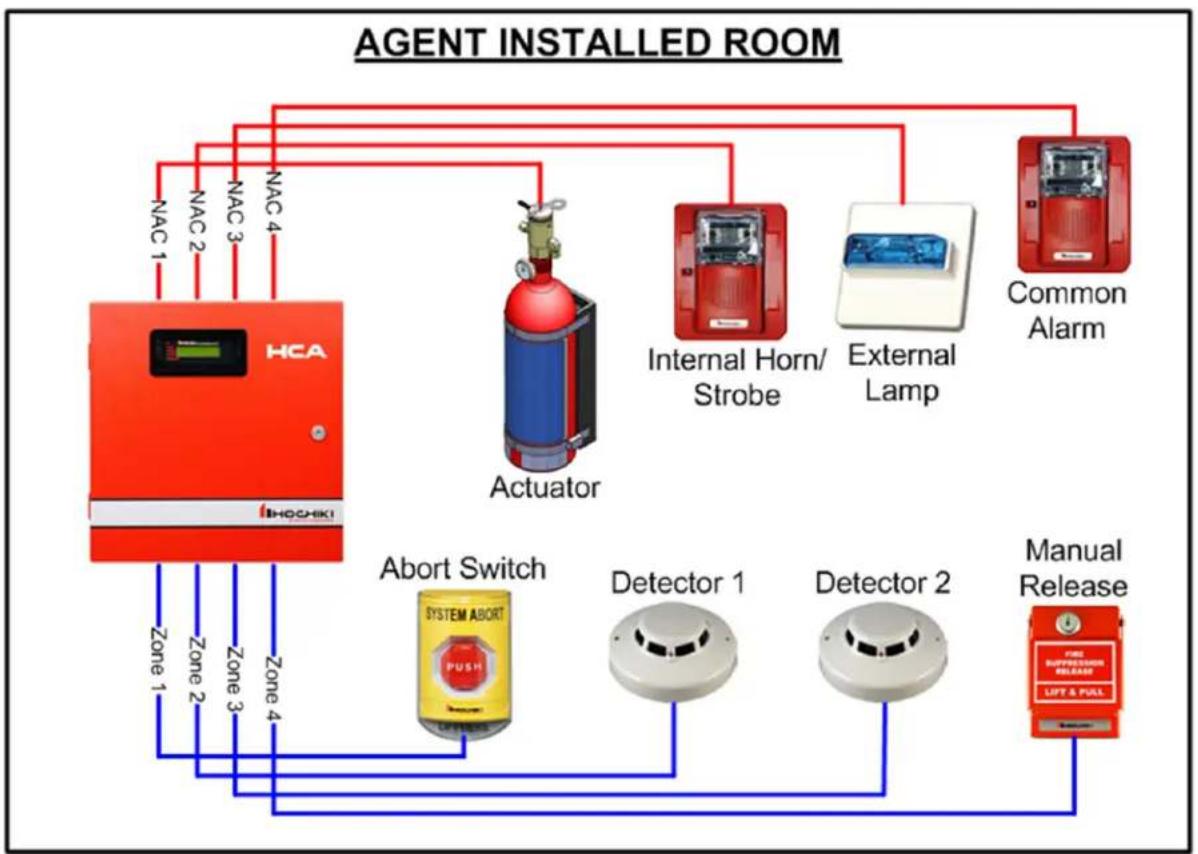
5.4.1 Agent Releasing
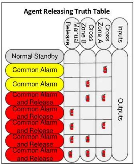
The agent releasing option configures the panel for the cross zone releasing configuration shown in figure 5.1. Figure 5.2 is a truth table that shows the cross alarm or manual release inputs that are needed for agent releasing to occur.
PROGRAMMING MENU 4-Releasing, Nxt
Pressing 4 will select the releasing programming options. Pressing the Next key will display the next programming menu option.
Set the release mode in the first screen.
Releasing Option Agent Release
Use the down arrow to scroll through None, Water Release and the Agent Release options. Once the desired release option is shown press the enter key to accept the option.
Select the pre-alarm delay time before the solenoid activates once cross zones 2 and 3 are both active.
Solenoid Cross Alarm Delay: 30
Select solenoid delay time. Default is 30 seconds. Possible range is 30-60 seconds.
Select whether the Solenoid output should be automatically shut down after the shutdown timer expires.
Auto Shutdown Solenoid(Y/N): Y
Choose the auto shutdown solenoid option. Select Y for the auto shutdown solenoid feature. Select N to leave the solenoid active until system reset. Press enter to accept displayed option on the screen. Default is Y (Yes).
If you select Y for Auto Shutdown Solenoid, the screen below will display to select the auto shutdown time.
Solenoid Shutdown Time: 030
Select solenoid delay time. Default is 30 seconds. Possible range is 10-600 seconds.
Finally, select the output cadence pattern for NACs 2, 3 and 4. NAC 1 cadence is always continuous.
Release Pattern Continuous
Use down arrow to scroll through cadence patterns for output circuits 2, 3 and 4 with the releasing function. Once the desired cadence is shown press enter key to accept cadence option.
The releasing cadence patterns are:
1) Continuous – The output will be on continuously.
2) Gentex Sync – Select this option if using Gentex appliances and you want the strobes in sync.
3) March Code – This option will produce a pattern of 5 seconds on, 5 seconds off
4) Temporal Code – This option will produce the ANSI 3.41 temporal coded pattern of 0.5 seconds on, 0.5 seconds off, 0.5 seconds on, 0.5 seconds off, 0.5 seconds on, 1.5 seconds off, repeat.
5.4.1.1 Zone and Output Definitions for Agent Releasing Option
When you configure the HCA panel for the agent releasing option, the zones and outputs are configured as follows:
- Zone 1 is configured as an abort zone. The abort function is non-latching. It must remain active as long as it is desired to abort the releasing function. If the abort switch is deactivated before the panel is reset, the remaining pre-alarm delay time will continue to count down to zero at which time releasing will occur.
- Zones 2 and 3 are configured for cross zone releasing. Zones 2 and 3 are intended to be populated with automatic initiating devices such as smoke detectors. When the first zone of zones 2 and 3 becomes active, output circuit 4 will activate indicating general alarm. When both zones 2 and 3 become active, a pre-alarm delay period (default 30 seconds) occurs where zone 1 can abort the releasing function. Output circuit 2 will activate at the beginning of the pre-alarm delay period to alert personnel of the pending agent release. If abort zone 1 is not activated by onsite personnel within the pre-alarm period, output circuit 1 will activate and discharge for either the programmed shutdown time or until system reset depending on the programming configuration. Output circuit 3 activates when output 1 activates and remains active until system reset indicating that the discharge has occurred. The cross zoning of zones 2 and 3 requires that at least one detector from each zone must be in alarm in order to activate the agent releasing output circuit 1 and the releasing indicator, output circuit 3.
- Zone 4 is a manual release zone. Manual releasing switches must be wired to zone 4 so that when one or more release switches are activated, agent releasing occurs immediately. As soon as zone 4 activates, output circuit 4 activates indicating general alarm. There is no pre-alarm delay period for manual release, so output circuit 2 activates immediately along with circuits 1 and 3 which will release the agent and indicate that a release has occurred. An active manual release will override any pre-alarm delay that might be occurring with the cross alarms and activate the agent release immediately.
- Zone 5 of the HCA-8 is automatically configured as a normally-closed supervisory zone. This zone is used with the releasing circuit disconnect switch. When the switch is activated it does two things; it physically disconnects the releasing circuit, and it creates a supervisory condition on zone 5. See section 5.4.3 of this manual for additional information and wiring instructions.
- Zones 6 through 8 on the HCA-8 behave as non-releasing fire, alarm verification or supervisory zones based on the programming options for these zones.
- Output Circuit 1 is dedicated for the agent release function. It will activate (discharge) after the pre-alarm delay has expired for cross zones 2 and 3, or immediately after the manual release zone 4 is activated. To prevent the pre-alarm period from expiring and preventing the output circuit from agent release, the abort zone 1 must become active within the pre-alarm delay period. Output circuit 1 will automatically shut down once activated after the auto shutdown timer has expired or it will remain active until system reset depending on the panel programming.
- Output Circuit 2 activates during the pre-alarm period to indicate the pending release and stays active after the agent releasing circuit 1 activates and until the panel is reset.
- Output Circuit 3 activates at the same time as the agent release circuit 1 to indicate a release has occurred and stays active until the panel is reset.
- Output Circuit 4 activates when at least one of zone 2, 3 or 4 activate to indicate general alarm. Output Circuit 4 may also operate in response to zones 6 – 8 of the HCA-8, depending on their programming.
flowchart
graph TD
    A["HCA"] -->|NAC 1| B["Actuator"]
    A -->|NAC 2| B
    A -->|NAC 3| B
    A -->|NAC 4| B
    B --> C["Internal Horn/ Strobe"]
    B --> D["External Lamp"]
    B --> E["Common Alarm"]
    B --> F["Abort Switch"]
    F --> G["Detector 1"]
    F --> H["Detector 2"]
    F --> I["Manual Release"]
    G --> J["FIRE SUFFRICATION RELEASE"]
    H --> J
    I --> J
    J --> K["LIFT & PULL"]
    style A fill:#f9f,stroke:#333
    style B fill:#ccf,stroke:#333
    style C fill:#cfc,stroke:#333
    style D fill:#fcc,stroke:#333
    style E fill:#cff,stroke:#333
    style F fill:#ffc,stroke:#333
    style G fill:#cfc,stroke:#333
    style H fill:#fcc,stroke:#333
    style I fill:#cfc,stroke:#333
Figure 5.1 – Agent Releasing Configuration
other
Agent Releasing Truth Table | Agent | Manual Release | Manual Release Zone B | Cross Zone A | Cross Zone B | Cross Zone A | Cross Zone B | Inputs | |---|---|---|---|---|---|---|---| | Normal Standby | | | | | | | Outputs | | Common Alarm | | | | | | | | | Common Alarm | | | | | | | | | Common Alarm and Release | | | | | | | | | Common Alarm and Release | | | | | | | | | Common Alarm and Release | | | | | | | | | Common Alarm and Release | | | | | | | | | Common Alarm and Release | | | | | | | | | Common Alarm and Release | | | | | | | | InputsFigure 5.2 – Agent Releasing Truth Table
5.4.2 Water Releasing
There is both a single interlock and double interlock water releasing programming option. The single interlock release has similar behavior to the agent release programming option. The difference between single interlock and agent releasing is that zone 1 is configured as a supervisory zone for single interlock vs. an abort function for agent releasing. Note also that there is no pre-alarm delay for a cross alarm of zones 2 and 3 with water releasing as there is for agent releasing.
The double interlock zone uses zone 1 as the interlock switch alarm zone. The interlock switch is required to be active along with a cross alarm of zones 2 and 3, or the manual release zone 4 in order for there to be a release.
See figure 5.3 for the water releasing truth table indicating what zones must be active in order for there to be a water release.
To set up the panel for the water releasing select option 4 from the main menu.
PROGRAMMING MENU 4-Releasing, Nxt
Select 4 from the main menu for general releasing.
Select the Water Release mode.
Releasing Option Water Release
Use the down arrow to scroll through None, Water Release and Agent Release options. Once the desired release option is shown press the enter key to accept the option.
Select either single or double pre-action mode for the water release option.
Pre-Action Mode Single Interlock
Use the down arrow to scroll through Single Interlock and Double Interlock. Once the desired interlock mode is shown press enter key to accept the option.
Select whether the Solenoid output should be automatically shut down after the shutdown timer expires.
Auto Shutdown Solenoid(Y/N): Y
Choose the auto shutdown solenoid option. Select Y for auto shutdown solenoid feature. Select N to leave solenoid active until system reset. Press enter to accept option displayed on the screen. Default is Y (Yes).
If you select Y for Auto Shutdown Solenoid, the screen below will display to select the auto shutdown time.
Solenoid Shutdown Time: 030
Select solenoid delay time. Default is 30 seconds. Possible range is 10-600 seconds.
Finally, select the output cadence pattern for NACs 2, 3 and 4. NAC 1 is always the continuous pattern.
Release Pattern Continuous
Use down arrow to scroll through cadence patterns for output circuits 2, 3 and 4 with the releasing function. Once desired cadence is shown press the enter key to accept cadence option.
The releasing cadence patterns are:
1) Continuous - The output will be on continuously.
2) Gentex Sync – Select this option if using Gentex appliances and you want the strobes in sync.
3) March Code – This option will produce a pattern of 5 seconds on, 5 seconds off
4) Temporal Code – This option will produce the ANSI 3.41 temporal coded pattern of 0.5 seconds on, 0.5 seconds off, 0.5 seconds on, 0.5 seconds off, 0.5 seconds on, 1.5 seconds off, repeat.
5.4.2.1 Zone and Output Definitions for Water Releasing Options
When you configure the HCA panel for single or double interlock water releasing, the zones and outputs are configured as follows:
- Zone 1 is configured as a supervisory zone for the single interlock option. You would normally use this to monitor sprinkler piping pressure in single interlock applications.
- Zone 1 is configured as an interlock switch alarm zone for the double interlock option. In order for a release to occur both the double interlock zone (zone 1) and either the manual release zone or both cross alarm zones must be active.
- Zones 2 and 3 are configured for cross zone releasing. Zones 2 and 3 are intended to be populated with automatic initiating devices such as smoke detectors. When the first zone of zones 2 and 3 becomes active, output circuit 4 will activate indicating general alarm. The cross zoning of zones 2 and 3 requires that at least one detector from each zone must be in alarm in order for the cross zone alarm to be active which will cause a water release for single interlock and may occur for double interlock depending on the state of the interlock zone 1.
- Zone 4 is a manual release zone. Manual releasing switches must be wired to zone 4 so that when one or more release switches are activated, a water release for single interlock will occur and may occur for double interlock depending on the state of the interlock zone 1.
- Zone 5 of the HCA-8 is automatically configured as a normally-closed supervisory zone. This zone is used with the releasing circuit disconnect switch. When the switch is activated it does two things; it physically disconnects the releasing circuit, and it creates a supervisory condition on zone 5. See section 5.4.3 of this manual for additional information and wiring instructions.
- Zones 6 through 8 on the HCA-8 behave as non-releasing fire, alarm verification or supervisory zones based on the programming options for these zones.
- Output Circuit 1 is dedicated for the water release solenoid(s). It will activate when the release requirements for single or double interlock have all been met. Output circuit 1 will automatically shut down once activated after the auto shutdown timer has expired or it will remain active until system reset depending on the panel programming.
- Output Circuit 2 activates at the same time as output 1 for water releasing because there is no cross alarm delay for water releasing. Output 2 stays active until the panel is reset.
- Output Circuit 3 activates at the same time as output 1 to indicate a release has occurred and stays active until the panel is reset.
- Output Circuit 4 activates when at least one of zone 2, 3 or 4 activate (or zone 1 for double interlock) to indicate general alarm. Output Circuit 4 may also operate in response to zones 6 – 8, depending on their programming.
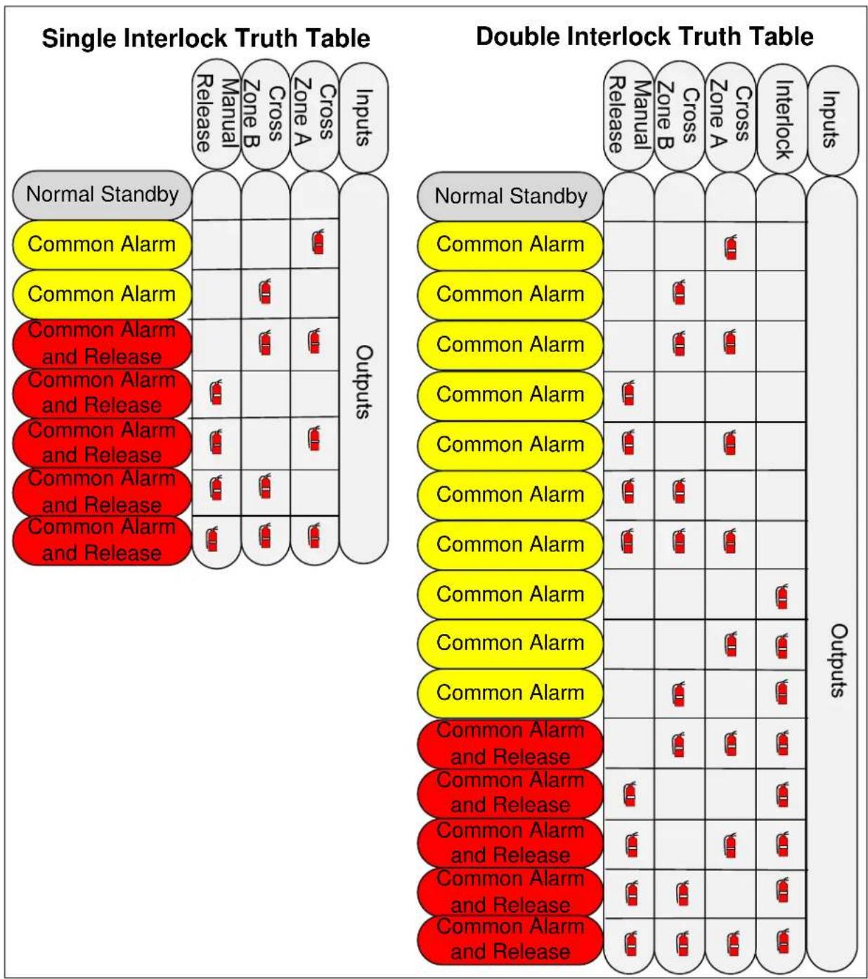
bar
| Interlock Type | Manual Release | Cross Zone B | Cross Zone A | Inputs | | :--- | :--- | :--- | :--- | :--- | | Normal Standby | 0 | 0 | 0 | 0 | | Common Alarm | 0 | 0 | 1 | 0 | | Common Alarm | 0 | 1 | 0 | 0 | | Common Alarm and Release | 0 | 1 | 1 | 0 | | Common Alarm and Release | 1 | 0 | 1 | 0 | | Common Alarm and Release | 1 | 0 | 1 | 0 | | Common Alarm and Release | 1 | 0 | 1 | 0 | | Common Alarm and Release | 1 | 1 | 0 | 0 | | Common Alarm and Release | 1 | 1 | 0 | 0 | | Common Alarm and Release | 1 | 1 | 1 | 0 | Double Interlock Truth Table: Manual Release, Cross Zone B, Cross Zone A, Interlock, Inputs. Outputs are shown in the table.Figure 5.3 – Water Releasing Truth Table
5.4.3 How to Install the Disconnect Switch on the Releasing Circuit
NFPA requirements state that a releasing service fire alarm system shall be provided with a disconnect switch to allow the system to be tested without actuating the fire suppression systems. This disconnect switch shall be a physical switch. When the switch is operated the panel shall indicate a supervisory signal at the control unit (NFPA 72 2010 Edition, 23.13.5). This section explains how to connect the disconnect switch to the HCA.
You will need a Hochiki America SOM-R-DS Disconnect Switch for this application.
The disconnect switch is connected in-line with the releasing circuit (NAC 1). When the switch is operated, it creates an open-circuit condition which prevents the release of the extinguishing agent. The switch is also connected to Zone 5 on the panel. When the switch is operated to disable NAC 1, zone 5 will be activated to indicate a supervisory signal at the panel.
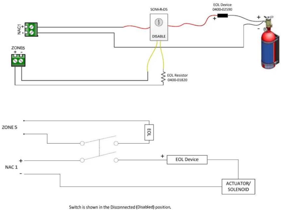
flowchart
graph TD
    A["NAC1"] --> B["ZONE5"]
    C["+"] --> D["SOM-R-DS DISABLE"]
    D --> E["EOL Device 0400-02590"]
    E --> F["+"]
    G["+"] --> H["+"]
    I["EOL Resistor 0400-01820"] --> D
    J["+"] --> K["+"]
    L["+"] --> M["+"]
    N["ZONE5"] --> O["EOI"]
    P["NAC1"] --> Q["+"]
    R["+"] --> S["EOL Device"]
    T["+"] --> U["ACTUATOR/ SOLENOID"]
    V["+"] --> W["+"]
    X["+"] --> Y["+"]
    Z["+"] --> AA["+"]
    AB["+"] --> AC["+"]
    AD["+"] --> AE["+"]
    AF["+"] --> AG["+"]
    AH["+"] --> AI["+"]
    AJ["+"] --> AK["+"]
    AL["+"] --> AM["+"]
    AN["+"] --> AO["+"]
    AP["+"] --> AQ["+"]
    AR["+"] --> AS["+"]
    AT["+"] --> AU["+"]
    AV["+"] --> AW["+"]
    AX["+"] --> AY["+"]
    AZ["+"] --> BA["+"]
    BB["+"] --> BC["+"]
    BD["+"] --> BE["+"]
    BF["+"] --> BG["+"]
    BH["+"] --> BI["+"]
    BJ["+"] --> BK["+"]
    BL["+"] --> BM["+"]
    BN["+"] --> BO["+"]
    BP["+"] --> BQ["+"]
    BR["+"] --> BS["+"]
    BT["+"] --> BU["+"]
    BV["+"] --> BW["+"]
    BX["+"] --> BY["+"]
    BZ["+"] --> CA["+"]
    CB["+"] --> CC["+"]
    CD["+"] --> CE["+"]
    CF["+"] --> CG["+"]
    CH["+"] --> CI["+"]
    CJ["+"] --> CK["+"]
    CL["+"] --> CM["+"]
    CN["+"] --> CO["+"]
    CP["+"] --> CY["+"]
    CZ["+"] --> DA["+"]
    DB["+"] --> DC["+"]
    DD["+"] --> DE["+"]
    DF["+"] --> DG["+"]
    DH["+"] --> DI["+"]
    DJ["+"] --> DK["+"]
    DL["+"] --> DV["+"]
    DW["+"] --> DX["+"]
    DX --> DW
    DX --> DX
    DX --> DX
    DX --> DX
    DX --> DX
    DX --> DX
    DX --> DX
    DX --> DX
    DX --> DX
    DX --> DX
    DX --> DX
    DX --> DX
    DX --> DX
    DX --> DX
    DX --> DX
    DX --> DX
    DX --> DX
    DX --> DX
    DX --> DX
    DX --> DX
    DX --> DX
    DX --> SX
    DX --> SX
    DX --> SX
    DX --> SX
    DX --> SX
    DX --> SX
    DX --> SX
    DX --> SX
    DX --> SX
    DX --> SX
    DX --> SX
    DX --> SX
    DX --> SX
    DX --> SX
    DX --> SX
    DX --> SX
    DX --> SX
    DX --> SX
    DX --> SX
    DX --> SX
    DX --> RX
    DX --> RX
    DX --> RX
    DX --> RX
    DX --> RX
    DX --> RX
    DX --> RX
    DX --> RX
    DX --> RX
    DX --> RX
    DX --> RX
    DX --> RX
    DX --> RX
    DX --> RX
    DX --> RX
    DX --> RX
    DX --> RX
    DX --> RX
    DX --> RX
    DX --> RX
    DX --> SX
    DX --> SX
    DX --> SX
    DX --> SX
    DX --> SX
    DX --> SX
    DX --> SX
    DX --> SX
    DX --> SX
    DX --> SX
    DX --> SX
    DX --> SX
    DX --> SX
Figure 5.4 – Disconnect Switch for Releasing
Additional notes about Releasing:
- The only programmable options for zones 1 – 5 are the relay settings when releasing is selected.
- The 4-zone HCA panel does not have the capability of supporting a disconnect switch because the panel only has four zones; there is no zone 5. The 4-zone HCA may be used for applications where a disconnect switch is not required. ALWAYS confirm with your AHJ before installing the system!
When the disconnect switch is operated it will result in two messages on the HCA control panel:
- A Supervisory event on zone 5
- A "NAC CIRCUIT 1 Trouble" event
When these events are present on the panel ensure that the disconnect switch is in the intended position. The disconnect switch should always be in the ENABLED position except when service or maintenance is being performed.
5.5 Remote Annunciator
The programming option to indicate the presence of a remote annunciator is located in option 5 of the programming menu. The HCA panel supports up to 1 remote annunciator.
PROGRAMMING MENU 5-RemoteDis, Nxt
Pressing 5 will select the remote annunciator menu. Pressing the Next key will display the next programming menu option.
The screen below displays after selecting option 5.
Annunciator En 1 No
Select Yes if you are going to use the remote annunciator or select no if no remote annunciator will be used.
5.6 DACT Setup
Models HCA-2D, HCA-4D and HCA-8D have a built in Digital Alarm Communicator Transmitter (DACT) for reporting events via telephone lines to a compatible remote central station receiver. Select Option 6 from the programming menu to edit the DACT programming options.
PROGRAMMING MENU 6-Edit DACT, Nxt
Pressing 6 will select the DACT programming options. Pressing the Next key will display the next programming menu option.
5.6.1 Enable/Disable the DACT
There is a master enable flag for the DACT which allows the installer to enable or disable the DACT easily without changing any other DACT programming options. Note that the panel will not be in trouble if you turn off the DACT using this master enable flag. It is an acceptable programming configuration to use one of the HCA panels that includes the DACT hardware, but not actually enable the DACT. The default setting for this enable flag is No. You will need to enable the DACT and properly program account numbers and phone numbers before it will be able to report events. Models without the DACT hardware will not display the enable/disable DACT option.
Enable DACT (Y/N): N
Press Y and Enter to enable the DACT. Press N and Enter to turn off the DACT.
5.6.2 Auto Test Time of Day
The auto test is a daily test (every 6 or 24 hours) that will report a test code to the remote central station receiver to indicate that the panel is capable of remote communications. The auto test will alternate the phone line used to ensure that each phone line is in good working order.
The first DACT programming screen is the hour of the day the auto test will occur.
Auto Test Time Hour(0-23):02
Enter the hour when the auto test will occur followed by Enter. Default time is 2:00AM.
The next DACT programming screen is the minute within the hour of the day for the auto test.
Auto Test Time Minute(0-59): 00
Enter the minute the auto test will occur followed by Enter. Default time is 2:00AM.
The next DACT programming screen sets the interval for the auto test.
AutoTest Period: Run Every 6 hrs
The auto test interval may be set to 24 hours or 6 hours. Use the down arrow key to toggle between the two selections.
5.6.3 Low AC Reporting Delay
The Low AC reporting delay is the delay between when a low AC input power condition is detected by the panel and when it gets reported to the central station via the DACT. To be in compliance with UL 864, it is required that this delay be set between 1 hour (60 minutes) and 3 hours (180 minutes). The HCA panel allows for this parameter to be set between 1 minute and 990 minutes for installations that will allow this time to be set outside of the 60 to 180 minute UL864 requirement.
Low AC Reporting Delay (min): 180
Enter the number of minutes for the low AC reporting delay followed by the Enter key. Default value is 180 minutes.
5.6.4 Edit Accounts
There are 4 reporting accounts within the DACT which can be used for reporting the various reportable events to different receivers and/or phone numbers. See table 6.1 for a list of all events that can be reported to the central station and which reporting filter is associated with each possible event.
To edit any of the accounts, select Y (yes) and then enter. To skip past the edit accounts menus select N (no) and the Enter key.
Edit Accounts (Y/N): Y
Select Y and Enter to edit the account options.
Next, select which of the 4 accounts you wish to edit (possible values 1-4).
Select Which Account (1-4):
Enter the account index you want to edit.
5.6.4.1 Account Number
Each account has a 6 digit string called the account number that is sent to the central station to identify which account is sending the event(s). The DACT allows up to 6 digits to be used for the account number. If less than 4 digits are used, leading zeros are padded in front of the number to make the account number have a minimum of 4 digits. Contact ID uses only 4 digits. The 4 least significant digits of the account number are used for Contact ID; the upper 2 digits are not used with contact ID, even when more than 4 digits are entered for the account number. Account numbers for SIA can be 4-6 digits in length.
You may enter blanks or spaces in the account number by pressing the Silence key for the 2 most significant digits. The ESC key will back the cursor left one position until you reach the left most digit and then it will escape out of the account edit menu.
Account Number: 123456
Enter the account number you want to use for reporting.
5.6.4.2 Reporting Format
The DACT supports both Contact ID and SIA reporting formats. Use the up or down arrows to scroll through the reporting format selection and press the Enter key when the format you want is visible in the display screen.
Reporting Format CID
Select the reporting format desired for this account.
5.6.4.3 Alarm Reporting Filter
The alarm reporting filter determines if this account will report alarms and alarm restores to the central station.
Report Alarms (Y/N): Y
Select Y if you want alarms reported to this account. Select N if you do not want alarms reported.
5.6.4.4 Supervisory Reporting Filter
The supervisory reporting filter determines if this account will report supervisory and supervisory restores to the central station.
Report Suprvisry (Y/N): Y
Select Y if you want supervisory reported to this account. Select N if you do not want supervisory reported.
5.6.4.5 Trouble Reporting Filter
The trouble reporting filter determines if this account will report trouble and trouble restore events to the central station.
Report Trouble (Y/N): Y
Select Y if you want troubles reported to this account. Select N if you do not want troubles reported.
5.6.4.6 Tests Reporting Filter
The tests reporting filter determines if this account will report tests and test restore events to the central station.
Report Tests (Y/N): Y
Select Y if you want test events reported to this account. Select N if you do not want test events reported.
5.6.4.7 Fire Drill Reporting Filter
The fire drill reporting filter determines if this account will report fire drill begin and fire drill end events to the central station.
Report FireDrill
(Y/N): Y
Select Y if you want fire drill events reported to this account. Select N if you do not want test events reported.
5.6.4.8 Disable/Enable Circuits Reporting Filter
The disable reporting filter determines if this account will report circuit disable and enable events to the central station.
Report Disables
(Y/N): Y
Select Y if you want disable and enable circuit events reported to this account. Select N if you do not want disable and enable events reported.
5.6.4.9 Primary Phone Number
Each account has a 20 digit primary phone number for calling the central station. The primary phone number is always used first; the secondary phone number is only used when the DACT is unable to communicate using the primary phone number.
In addition to the digits "0" through "9", you can also insert commas "," that will generate pauses between the digits being dialed. This might be useful when you need to dial an outside line when connected to a local PBX. To enter a comma, the "ACK" key is used when entering the phone number. Commas count as part of the 20 digit limitation in the phone number. You can also enter spaces by using the SILENCE key. The ESC key will back the cursor left one position until you reach the left most digit and then it will escape out of the phone number edit menu.
PrimaryPhoneNum:
Enter the first phone number to call when this account needs to report an event.
5.6.4.10 Secondary Phone Number
Each account has a secondary phone number for calling the central station when the account is unable to get through on the primary number. If you only want to have the account attempt to call one number you can program the primary number in both the secondary and primary programming locations.
SecondPhoneNum:
Enter the secondary number to call when this account cannot report events using the primary phone number
5.6.5 Edit Phone Lines
The DACT has 2 phone lines for reporting to a central station receiver. Both lines must be used for proper operation of the DACT. In addition, both phone lines must be supervised for the panel installation to be compliant with UL864 – see section 5.6.5.2.
Edit Phone Lines
(Y/N): N
If you want to edit the programming options specific to the phones lines, enter Y and the Enter key to see the first programming screen on the phone lines.
Select which phone line you want to edit.
Select Phone Line: (1-2):
Enter 1 or 2 followed by the Enter key.
5.6.5.1 Dialing Format
Select which dialing format you would like this line to use. You can chose to only use touch tone dialing, a combination of touch tone and pulse dialing when multiple call attempts are needed, or pulse dialing only for dialing the phone number.
Dialing Format: Dial Tones Only
Use the up or down arrow keys to select tone dialing only, tone and pulse dialing, or pulse dialing only.
5.6.5.2 Supervise Phone Line
You can select whether the line is to be supervised for phone line voltage or not by selecting Y (yes) or N (no). Normally, you always want to supervise the phone line and it is a requirement for UL864 and NFPA compliant installations. Default is Y.
Supervise Line (Y/N): Y
Enter Y or N to indicate if the line is to be used or not.
5.7 Panel Factory Default Setup
If there is ever a need to start over with the programming process the panel can be brought back to the default factory programming settings. From the programming menu select option 7
PROGRAMMING MENU 7-Defaults, Nxt
Pressing 7 will select the programming options to restore the factory default options. Pressing the Next key will take the display back to the option 1 programming menu screen.
The screen below will be displayed after select option 7.
LOAD DEFAULTS No
Select Yes and Enter to reload the manufacturer default settings. Select No and Enter, or Esc to skip defaulting the panel.
5.7.1 Factory Default Settings
Default factory settings:
1) All zones are configured as FIRE alarm type zones with 1 second response time.
2) All zones are mapped to all 4 NAC outputs with continuous cadence pattern for alarm.
3) Dead shorts on zone inputs are interpreted as alarm, not trouble. (shorted mode = alarm)
4) The releasing features are deactivated.
5) The DACT is deactivated.
6) The installer access code is defaulted to 3333.
7) The user access code is defaulted to 2222.
6. DACT Reporting Codes and Compatible Receivers
This section lists all central station receiver output codes that are used for all reportable events in the HCA panel. The HCA control panel is compatible with central station receivers that support SIA and/or Contact ID reporting formats such as those manufactured by ADEMCO, Silent Knight and Sur-Gard.
6.1 DACT Reporting Codes for SIA and Contact ID
The table below lists all reportable events in the HCA series control panel and the associated SIA and Contact ID reporting codes.
Table 6.1 Panel Output Codes for SIA and Contact ID Reporting Formats.
| SIA Reporting Format | Contact ID Reporting Format | |||||
| HCA Panel Event | HCA Reporting Filter Associated with This Event | Event Code | Parameter | Qualifier | Event Code | Contact # |
| Fire Zone Alarm Alarm FA Zone # 1 | 110 Zone # | |||||
| Fire Zone Alarm Restore Alarm FH Zone # 3 110 Zone # | ||||||
| Fire Zone Trouble Trouble FT Zone # 1 373 Zone # | ||||||
| Fire Zone Trouble Restore | Trouble FJ Zone # | 3 373 Zone # | ||||
| Fire Zone Disabled Disablement | FB Zone # 1 571 | Zone # | ||||
| Fire Zone Enabled | Disablement | FU Zone # 3 571 Zone # | ||||
| Supervisory Zone Active | Supervisory | SS Zone # 1 200 Zone # | ||||
| Supervisory Zone Restore | Supervisory | SR | Zone # | 3 | 200 | Zone # |
| Supervisory Zone Trouble | Trouble ST Zone # 1 373 Zone # | |||||
| Supervisory Zone Trouble Restore | Trouble | SJ | Zone # | 3 | 373 | Zone # |
| Supervisory Zone Disabled | Disablement | SB | Zone # | 1 | 571 | Zone # |
| Supervisory Zone Enabled | Disablement | SU | Zone # | 3 | 571 | Zone # |
| Notification Circuit Trouble | Trouble | FT | NAC # + 10 | 1 | 373 | NAC # + 10 |
| Notification Circuit Trouble Restore | Trouble | FJ | NAC # + 10 | 3 | 373 | NAC # + 10 |
| Fire Drill Begin | Fire Drill | FI | 0 | 1 | 604 | 0 |
| Fire Drill End | Fire Drill | FK | 0 | 3 | 604 | 0 |
| AC Power Trouble | Trouble AT 0 | 1 301 0 | ||||
| AC Power Trouble Restore | Trouble | AR | 0 | 3 | 301 | 0 |
| Battery Charger Trouble | Trouble | YP | 0 | 1 | 312 | 0 |
| Battery Charger Trouble Restore | Trouble | YQ | 0 | 3 | 312 | 0 |
| Low Battery Trouble | Trouble YT 0 | 1 302 0 | ||||
| Low Battery Trouble Restore | Trouble | YR | 0 | 3 | 302 | 0 |
| Battery Missing Trouble | Trouble | YM | 0 | 1 | 311 | 0 |
| Battery Missing Trouble Restore | Trouble | YR | 0 | 3 | 311 | 0 |
| Earth Ground Fault Trouble | Trouble | YP | 0 | 1 | 310 | 0 |
| Earth Ground Fault Trouble Restore | Trouble | YQ | 0 | 3 | 310 | 0 |
| Remote Annunciator Trouble | Trouble ET 1 | 1 333 1 | ||||
| Remote Annunciator Trouble Restore | Trouble | ER | 1 | 3 | 333 | 1 |
| Phone Line 1 Trouble | Trouble | LT | 1 | 1 | 351 | 1 |
| Phone Line 1 Trouble Restore | Trouble LR 1 | 3 351 1 | ||||
| Phone Line 2 Trouble | Trouble | LT | 2 | 1 | 352 | 2 |
| Phone Line 2 Trouble Restore | Trouble LR 2 | 3 352 2 | ||||
| DACT Account Trouble | Trouble RT Account # | 1 354 Account # | ||||
| DACT Account Trouble Restore | Trouble | YK | Account # | 3 | 354 | Account # |
| DACT Failure Trouble | Trouble | IA | 0 | 1 | 350 | 0 |
| DACT Failure Trouble Restore | Trouble | IR | 0 | 3 | 350 | 0 |
| Walk Test Begin | Test | TS Zone # 1 607 Zone # | ||||
| Walk Test End | Test | TE Zone # 3 607 Zone # | ||||
| Auto Test Normal Standby | Test | RP | 0 | 1 | 602 | 0 |
| Auto Test Off Normal | Test | RY | 0 | 1 | 608 | 0 |
| Manual DACT test | Test | RX | 0 | 1 | 601 | 0 |
| System Programming Begin | Trouble | LB | 0 | 1 | 627 | 0 |
| System Programming Ended | Trouble | LS | 0 | 1 | 628 | 0 |
| System Reset | Trouble | OR | 0 | 1 | 313 | 0 |
| Initial Power Up Reset | Trouble | RR | 0 | 1 | 305 | 0 |
| Time or Date Changed | Test | JT | 0 | 1 | 625 | 0 |
7. Compatible Devices for the HCA Series Panel
7.1 Compatible Conventional Initiating Devices
| Hochiki America Initiating Devices | ||
| Maximum number per zone | ||
| Detectors | ||
| SLV-24V Photoelectric high velocity smoke detector 20 | ||
| SLV-24N Photoelectric high velocity smoke detector 20 | ||
| SLR-24H Photoelectric smoke/heat detector 20 | ||
| SLR-24V 24VDC Photoelectric smoke detector 20 | ||
| SLR-835 8 – 35VDC Photoelectric smoke detector 20 | ||
| DSC-EA Rate of rise heat detector 20 | ||
| DCD-135 Fixed temperature rate of rise heat detector 20 | ||
| DCD-190 Fixed temperature rate of rise heat detector 20 | ||
| BASES | ||
| NS6-224 | 43mA draw, 24V | 20 |
| NS4-224 | 43mA draw, 24V | 20 |
| NS6-100 150mA maximum, 24V | 20 | |
| NS4-100 150mA maximum, 24V | 20 | |
| PULL STATION | ||
| HPS-SAK/HPS-DAH | Conventional Manual Pull Station | 25 |
| HPS-SAH/HPS-DAK | Conventional Manual Pull Station | 25 |
7.2 Compatible Releasing Devices
| Compatible Releasing Devices | |
| Agent Releasing Actuator | |
| TSP 131-035 | Electrical Actuator/Solenoid |
| Sevo Systems - SOL EA45 | Electrical Actuator/Solenoid |
| TLX Technologies - PA0036-3 | Electrical Actuator/Solenoid |
| Water Releasing Solenoids | |
| Parker/Skinner - 73218BN4UNLVNOC111C2 | Solenoid |
| Parker/Skinner - LV2LBX25 | Solenoid |
| Parker/Skinner - X5H65100 24Volt | Solenoid |
| ASCO - T8210A107 | Solenoid |
| ASCO - R8210A107 | Solenoid |
| ASCO - 8210A107 | Solenoid |
| ASCO - HV2185328 | Solenoid |
| Victaulic - 753-E FireLock 300 psi | Solenoid |
| Viking -11591 | Solenoid |
| Releasing Abort Switch | |
| 0300-1000 | Abort Switch |
| PB-SA (0500-06440) | Abort Switch |
| Manual Release Switch | |
| HPS-DAK-SR | Manual Release Pull Station |
| Releasing EOL Module | |
| 0400-02590 | EOL releasing module |
7.3 Compatible Heat Detector Cable
| Compatible Devices | |||
| Manufacturer | Models | Description | Maximum Length |
| Proline Protection Systems LTD | TH 68 | Fixed Temp. line type heat detector cable 68^ ( 155^ ) | 8,000 feet (2,438m) |
| Proline Protection Systems LTD | TH 88 | Fixed Temp. line type heat detector cable 88^ ( 190^ ) | 8,000 feet (2,438m) |
| Proline Protection Systems LTD | TH 105 | Fixed Temp. line type heat detector cable 105^ ( 221^ ) | 8,000 feet (2,438m) |
7.4 Compatible Notification Appliances
The following devices from Gentex are compatible for use with the HCA control panel for synchronized applications on NAC 1, NAC 2, NAC 3, and NAC 4:
Note: To determine the maximum quantity of notification appliances that can be used per NAC circuit use the worst case current consumption for the appliance models chosen and make sure the total current for all appliances does not exceed the maximum current rating of the HCA NAC circuit.
| Gentex | Environment | Model Series | Description | Mount |
| WSSPK Series | Outdoor | WSSPK24-15/75 | Speaker Strobe | Wall |
| SSPK24WLP Series | Indoor | SSPK24WLP | Speaker Strobe | Wall |
| SSPKCLP Series | Indoor | SSPK24CLP | Speaker Strobe | Ceiling |
| Commander4 Series | Indoor | GCC24 | Horn Strobe | Ceiling |
| Commander4 Series | Indoor | GCS24 | Strobe | Ceiling |
| Commander3 Series | Indoor | GEC3-24 | Horn Strobe | Wall |
| Commander3 Series | Indoor | GES3-24 | Strobe | Wall |
| Commander3 Series | Indoor | GEH24 | Horn | Wall |
| Commander2 Series | Indoor | GEC24 | Horn Strobe | Wall |
| Commander2 Series | Indoor | GES24 | Strobe | Wall |
| Commander2 Series | Indoor | GEH24 | Horn | Wall |
| Outdoor Commander Series | Outdoor | WGEC24 | Horn Strobe | Wall |
| Outdoor Commander Series | Outdoor | WGES24 | Strobe | Wall |
| Outdoor commander Series | Outdoor | GEH24 | Horn | Wall |
| GX91/GX93 Series | Indoor | GX93 | Mini Horn | Wall |
8. Warranty
Hochiki America Corporation manufactured equipment is guaranteed to be free from defects in materials and workmanship for a period of three (3) years from date of original shipment. HOCHIKI will repair or replace, at its option, any equipment which it determines to contain defective material or workmanship. Said equipment must be shipped to HOCHIKI prepaid. Return equipment will be prepaid by HOCHIKI. We shall not be responsible to repair or replace equipment which has been repaired by others, abused, improperly installed, altered or otherwise misused or damaged or exposed to conditions outside the products specifications in any way. Unless previously contracted by HOCHIKI, HOCHIKI will assume no responsibility for determining the defective or operative status at the point of installation, and will accept no liability beyond the repair or replacement of the product at our factory service department. Please contact HOCHIKI's Sales department for proper procedure for claims and return of merchandise.
Hochiki America Corporation
7051 Village Drive, Suite 100
Buena Park, CA 90621-2268
1-800-845-6692
technicalsupport@hochiki.com
End of Manual
Updated July 2013