
GM6A-RST - Radio Interface PAC - Free user manual and instructions
Find the device manual for free GM6A-RST PAC in PDF.


| Product Type | Radio Interface Module |
| Compatible Vehicles | Select General Motors vehicles with 29-bit LAN v2, 20-pin and 16-pin connector radios |
| Dimensions | Approx. 4.0 x 2.0 x 1.0 inches (10.2 x 5.1 x 2.5 cm) |
| Weight | 0.2 lb (90 g) |
| Power Supply | 12V DC vehicle electrical system |
| Retained Factory Features | BOSE audio, OnStar, vehicle settings, steering wheel controls (SWC), front/rear park assist, warning chimes |
| Data Bus Outputs | Retained accessory power (RAP), vehicle speed signal (VSS), illumination, reverse trigger, parking brake |
| Steering Wheel Control (SWC) Support | Yes, pre-programmed; re-assignable via programming button |
| Aftermarket Radio Compatibility | Alpine, JVC, Kenwood, Clarion, Pioneer, Sony, Stinger, and others (selectable via DIP switches) |
| Camera Input | Supports factory rear camera retention; optional VS41 for multi-camera |
| Chime Speaker | Included for vehicles with aftermarket amplifiers |
| Firmware Updates | Via USB and RadioPRO PC Application |
| Programming Method | DIP switches and programming button; PC application for advanced settings |
| Installation Requirements | Professional installation recommended; cut brown mute loop for OnStar |
| Maintenance | No regular maintenance; keep connectors clean and dry |
| Safety Notes | Disconnect vehicle battery before installation; ensure proper wiring |
| Spare Parts / Accessories | Harnesses (vehicle connectors, adapters), chime speaker, CAM-GM51 harness, VS41 |
| Repair Policy | Contact PAC technical support for issues; no user-serviceable parts |
| Operating Temperature | -40°C to +85°C (-40°F to +185°F) |
| Country of Origin | China |
Frequently Asked Questions - GM6A-RST PAC
User questions about GM6A-RST PAC
0 question about this device. Answer the ones you know or ask your own.
Ask a new question about this device
Download the instructions for your Radio Interface in PDF format for free! Find your manual GM6A-RST - PAC and take your electronic device back in hand. On this page are published all the documents necessary for the use of your device. GM6A-RST by PAC.
USER MANUAL GM6A-RST PAC
Introduction and Features
The GM6A-RST interface allows the replacement of a factory radio in select General Motors vehicles with 29-bit LAN v2, 20-pin and 16-pin connector radios. Using this interface will retain factory features such as BOSE, OnStar, vehicle settings, steering wheel controls (SWC), front and rear park assist and warning chimes when the original radio is removed. The GM6A-RST also provides data bus driven outputs such as retained accessory power (RAP), vehicle speed (VSS), illumination, reverse trigger and parking brake.
Important Notes
- Please make your vehicle settings selections before removing the factory radio for optimal installation time. Once the radio has been removed, the vehicle settings which are normally selected through the factory radio can be accessed and changed by downloading and installing the PAC RadioPRO PC Application from http://www.pac-audio.com/firmware.
- Before removing your factory radio, please review the following settings as these will not be retained once the factory radio is removed:
- Ambient Lighting Control
- Teen Driver Feature
- Valet Mode
-
Rear Park Assist Symbols displayed on Reverse Camera Image
-
When you plug in the module for the first time, it must go through an initialization process that takes up to 12 seconds. Make sure you have the vehicle running diring this process.
- The radio select dip-switchs on the side of the interface must be adjusted to the proper radio setting before plugging the interface into the vehicle (see page 2 for setting chart).
- The Voice button can be set to activate the factory OnStar function by using the RadioPRO PC Application. By default, this button is re-programmed to control the aftermarket radios voice function.
- The interface comes pre-programmed for all of the vehicles factory SWC functions and does not require programming unless you wish to re-assign the SWC functions, utilize the buttons that have no initial programming or utilize short press long press dual command functionality. The SWC can always be restored to default settings by pressing and releasing the program button on the side of the interface once and waiting 7 seconds for the LED to flash 4 times.
• Chevrolet Malibu and Camaro will require SWC re-mapping. Failure to do this will result in irregular steering wheel control functionality.
• Chevrolet Camaro: You will not be able to control the volume of OnStar or launch OnStar with the SWC.
- The VS41 can be added to control Rear, Frotn, Left, Right cameras through the interface. See Page 5 for details.
- Language: In some vehicles the Lauguage setting is controlled over MOST. Please make sure that you adjust this accordingly before removing the radio as this will not show up in most cases after your install.
- For Referencing (IO) Codes. Please refer the vehicles RPO CODE sticker normally located in the vehicles glove box or the underside of the spare tire cover.
Module Layout

DIP switches

Interface Connector 1 Interface Connector 2 Interface Connector 3
Installation Steps

Set DIP switches that correspond with your radio to the ON position. Set all other DIP switches to the OFF position.

| Alpine JVC | Kenwood / Lightning Audio | Stinger | Clarion / Nakamichi | All Other Brands | Pioneer Sony Fusion | |
| 1 2 1 & | 2 3 3 1, 2, & 3 | 1, 2, & 3 4 1 & 4 |
If your brand is not listed above, please use "ALL OTHER BRANDS."
- Set the Radio Select DIP switches according to the radio you are installing.
- Wire your aftermarket radio to the GM6A-RST's harness according to the wiring connections chart on Page.3.
- Cut the Brown mute loop in Interface Connector 4. If not cut will turn the GM6A's accessory output off, when any OnStar function is active.
- Plug Interface Connectors 1 & 2 into the appropriate ports on the GM6A-RST interface (using the diagram on page 1 or the label on the bottom of the interface).
- The Interface Connector 3 connection port will be dependent upon whether or not the vehicle has a factory amplified system. Plug this connector into the appropriate port on the GM6A-RST (using the diagram on page 1 or the label on the bottom of the interface).
- Remove the factory radio and plug in the GM6A-RST's Vehicle Connector 1, 2, & 3 into the factory vehicle harness. Vehicle Connector 3 might not be present in all vehicles. In vehicles with IOA/IOB use Vehicle Connector 7 to adapt your main harness to your vehicle. (NOT FOR USE IN IMPALA, IMPROPER USE OF THIS HARNESS WILL RESULT IN EQUIPMENT DAMAGE.)
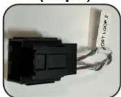
- Vehicle Connectors 4 & 5 are used when removing the factory CD player in the dash and are mandatory that they are plugged in to keep the MOST loop Intact. Failing to plug these in will result in no sound. Not all connectors may be present.
- Vehicle Connector 6 (GM5CAM-DIS-HAR) will only be used in vehicle with an IOB Build Code and will be connected to the harness that was plugged in to the factory display once removed. This is used to maintain the camera signal in IOB build code vehicles.

natural_image
Close-up of a white 3-pin connector with black, yellow, and red wires (no text or symbols visible)Interface Connector 1 (3-pin)
natural_image
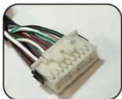
Close-up of a white electrical connector with multiple wires (no visible text or symbols)Interface Connector 2 (20-pin)
natural_image
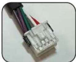
Close-up of a white electrical connector with multiple colored wires (no visible text or symbols)Interface Connector 3 (12-pin)
natural_image
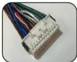
Close-up of a white electrical connector with multiple colored wires (no visible text or symbols)Interface Connector 4 (24-pin)
natural_image
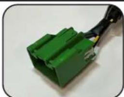
Close-up of a green plastic electrical connector with black wires (no visible text or symbols)Vehicle Connector 1 (20-pin)

natural_image
Close-up of a gray plastic electrical connector with wires (no visible text or symbols)Vehicle Connector 2 (16-pin)

natural_image
Close-up of a gray plastic electrical connector with green wires (no text or symbols visible)Vehicle Connector 3 (8-pin)

natural_image
Close-up of a multi-pin electronic component with gray, beige, and green connectors, no visible text or symbols on the main body.Vehicle Connector 7 (Adapter) NOT FOR IMPALA

natural_image
Close-up of a black USB drive with a white tag labeled 'MOST LOOP-1' attached to it (no other text or symbols visible)Vehicle Connector 4 (10-pin)
natural_image
Close-up of a black electronic component with attached cable (no visible text or symbols)Vehicle Connector 5 (12-pin)

natural_image
Two rectangular electronic components with wires attached, one partially visible (no text or symbols)Vehicle Connector 6 (20-pin)
Wiring Connections Chart
Aftermarket Radio Connections
| Yellow Constant 12V + | |
| Black Ground - | |
| Red Acc. Output | |
| White Front _left + input | |
| White / Black | Front Left - input |
| Grey | Front Right + input |
| Grey / Black | Front Right - input |
| Green | Rear Left + input |
| Green / Black | Rear Left - input |
| Purple | Rear Right + input |
| Purple / Black | Rear Right - input |
| Light Green Parking Brake Output (-) |
| Pink Vehicle Speed Output |
| Blue / White Remote Turn On |
| Blue Not Used |
| Orange / White Illumination Output (+) |
| Purple / White Reverse Output (+) |
| Brown Loop Mute Output (CUT) |
SWC Connector
| Blue / Yellow | Kenwood or Newer JVC |
| 3.5mm Jack | Alpine, JVC, Clarion, Pioneer, Sony, Boyo, Dual, Lightning Audio, Visteon or Advent |
Vehicle Side Connections
| Green / Black* S | WC Input |
IMPORTANT NOTES REGARDING GREEN / BLACK WIRE CONNECTIONS\*
There is a 60" Pigtail that is used for connecting the SWC input to the GM6A module that has a bullet connector on one end, and a loose wire on the other.
This is designed to plug into the matching bullet connector on the GM6X-HAR; both of which have a matching SWC Input label.
Wiring Connections (Con't)
- Make all connections as described in the chart above. Be sure to review all connections before plugging the harness into your vehicle.
- PLEASE NOTE: If you are installing this in any vehicle other than trucks and SUVs, it's best to make all connections behind the radio first, then pressing any button on the SWC and verifying that the LED on the module blinks. If it does, this step is not needed. If it does not, please proceed with this wiring connection.
In vehicles with an IO5 / IO6 RPO CODE, to retain the steering wheel control buttons you must hardwire them into the GM6A-RST. The wire you need to connect into can be found by removing the steering wheel shroud located beneath the steering wheel column, and accessing the wire in pin 9 at the Black 10-pin connector located at the base of the clock spring. (Fig. 1).

natural_image
Close-up of a car's engine bay with visible wiring and a white arrow pointing to a component (no text or symbols)Fig. 1
Once you have located the Green/Black wire in the vehicle you must connect the provided 60" Green/Black wire from the GM6A module. This is a data signal so to ensure consistent operation, it is highly recommended to solder this wired connection. DO NOT cut this wire in half. In some vehicles it may be necessary to remove the cover around the steering column and tag the wire in pin 9 at the Black 10-pin connector located at the base of the clock spring.
- Plug the chime speaker module in if needed. It is only necessary if you are connecting an aftermarket amplifier to the cabin speakers. Connect the chime speaker to the chime plug coming out of Interface Connector 3 and install the chime speaker in a place free of obstructions, where it can be easily heard (usually low in the dash facing downward).
- Connect the SWC wire or the 3.5mm SWC jack to the aftermarket radio according to the chart above (aftermarket radio MUST support a wired remote input).
- If you wish to reassign functions to the SWC, then follow the programming instructions on page 5.
- Connect the Red and White RCAs to the aftermarket radios AUX input to retain the factory 3.5mm AUX input jack.
- If the vehicle was equipped with the base level radio (IO3) and a factory reverse camera, then connect the Yellow RCA in the harness to the reverse camera input on the back of the radio. If your vehicle is equipped with the IO4, IO5 or IO6 system, follow notes "A & B" below for reverse camera retention. Please reference the vehicles RPO CODE sticker normally located in the vehicles glove box or the underside of the spare tire cover. Please Disreguard the Yellow RCA on the main GM6X-HAR when using the CAM-GM51.
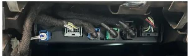
a. Connect the supplied CAM-GM51 Harness (Fig.2). The CAM-GM51 harness connects at the Human Machine Interface Control Module (HMICM), not at the radio. The HMICM is normally found behind the glove box in trucks and SUVs, or high in the passenger side kick panel area in other vehicles. The (HMICM) will have the USB and LVDS cables connected to it. (Pictured Below)
b. The factory reverse camera is powered by the vehicle, not the HMICM. The camera will continue to be powered even when disconnected from the HMICM, so no additional wiring is required to supply the camera with power.
natural_image
Interior view of a car showing electrical connector modules and wiring (no visible text or symbols)
natural_image
Close-up of a gray USB connector with visible internal wiring (no text or symbols)Fig. 2
Programming Button and Adjustment Dial Functions
You can press and hold the programming button on the side of the interface to access different programming modes. Once the LED is lit to the mode you desire (see below for modes), immediately release the programming button to access that mode.
PLEASE NOTE:
- This process must be done with the interface in the vehicle and the key in the ignition position.
- If there is a Bose system, and you are also installing an amplifier on the cabin speakers, make sure that the included chime speaker is connected.
A. LED 1 flash green: SWC re-assignment. This allows you to re-assign the SWC functions to the buttons of your choice. Please see the Optional Steering Wheel Control Programming instructions below for more details.
B. Both LEDs flash green: Chime volume adjustment. This allows you to adjust the volume of the chimes using the adjustment dial on the side. Please see note 6 under Testing and Verification for more details.
C. Both LEDs flash red: Master reset. This does a master reset of the interface and restores the following settings to factory defaults:
- SWC Mapping
- Camera Settings
• Infotainment Settings
• Interface User Options
Default Steering Wheel Control Programming
Default SWC Button Assignments
| Alpine | JVC | Kenwood | Clarion | Pioneer | Sony | Stinger | |
| Volume + | Volume + | Volume + | Volume + | Volume + | Volume + | Volume + | Volume + |
| Volume - | Volume - | Volume - | Volume - | Volume - | Volume - | Volume - | Volume - |
| Track Up | Track Up | Track Up | Track Up | Track Up | Track Up | Track Up | Track Up |
| Track Down | Track Down | Track Down | Track Down | Track Down | Track Down | Track Down | Track Down |
| Mode | Source | Source | Source | Source | Source | Source | Source |
| Voice | Voice | Voice | Voice | Voice | Voice | Voice | Voice |
| Phone | Phone Receive | Phone Receive | Answer Call | Answer / End Call | Answer Call | Answer/End Call | Answer / End Call |
Optional Steering Wheel Control Programming
Programming
- Turn the key to the ignition position.
- Press and release programming button on the side of the interface.
- Within 7 seconds, press the button that is to be learned on the steering wheel. LED 1 will turn red when the button is pressed. At this point you have two options:
A. For short press functionality: Release the button within 1.5 seconds. LED 1 will turn back to green.
B. For long press functionality: Hold the button until LED 1 starts blinking. Release the button and the LED will back to green.
-
Repeat step 3 for each additional audio function on the steering wheel.
-
If you come across a function in the chart that your steering wheel does not have, or you do not want to program, press and release the programming button on the side of the interface to skip that function.
- Once programming is completed, wait seven seconds and LED 1 will flash three times indicating that programming has finished.
- Test the interface for proper functionality. Whenever a button on the steering wheel is pressed, then LED 1 will illuminate green.
- If any function does not work, repeat the programming steps.
Optional Steering Wheel Control Programming (cont.)
Optional Programming Order
| Alpine JVC | Kenwood / Lightning Audio | Stinger | Clarion / Nakamichi | All other Brands | Pioneer Sony | |||
| 1 | Volume + | Volume + | Volume + | Volume + | Volume + | No specific programming order. Please refer to the owner's manual of your radio for SWC programming instructions. | Volume + | Volume + |
| 2 | Volume - | Volume - | Volume - | Volume - | Volume - | Volume - | Volume - | |
| 3 | Mute | Mute | Mute | Mute | Mute | Mute | Mute | |
| 4 | Preset + | Source | Source | Source | Source | Preset + | Preset + | |
| 5 | Preset - | Track + | Play | Search + | Search + | Preset - | Preset - | |
| 6 | Source | Track - | Track + | Search - | Search - | Source | Source / End Call | |
| 7 | Track + | Band / Disc + | Track - | Band | Band | Track + | Track + | |
| 8 | Track - | Preset / Disc - | Disc / FM + | Send / End | Send / End | Track - | Track - | |
| 9 | Power | Select | Disc / AM - | Send | Send | Band | Band | |
| 10 | Enter / Play | Attenuation | Answer | End | End | Phone Menu | Power / End Call | |
| 11 | Band / Program | Phone Receive | Voice | Voice | Voice | Answer Call | Voice / Answer / End Call | |
| 12Receive Phone Reject On Hook End Call | Voice (Android Auto & Car Play) Answer / End Call*** | |||||||
| 13 | End | Voice | Off Hook | Voice | ||||
| 14 | Voice | Power | Mute | |||||
| 15 | Preset + | |||||||
| If your brand is not listed above, please use “ALL OTHER BRANDS.” | ||||||||
| Please Note: On any entry with multiple commands, the commands shown are source dependent. | ||||||||
VS41 Functionality & Wiring
- The VS41 can be connected to the GM6A-RST and used to switch multiple cameras. Please refer to the document labeled "Instructions for wiring the VS41 with GM6A-RST" Which can be found on https://pac-audio.com under the VS41 product page.
RadioPRO PC App
Download the RadioPRO PC App at: https://pac-audio.com/app-downloads/
Use of the RadioPRO PC App allows you to do the following:
- Configure User Interface Options such as:
• Factory amplifier settings - Chime Volume
- Camera Settings
- Telematics Volume
- Change Vehicle Settings
- Update Product Firmware
- Read Firmware/Hardware Versions
PLEASE NOTE:
The interface must be connected to the vehicle when using the following features of the RadioPRO PC App:
• Factory Amplifier Settings
- Chime Volume
• Telematics Volume
- Change Vehicle Settings
• Interface User Options
- Camera Settings
The interface does not need to be connected to the vehicle when using the following features of the RadioPRO PC App:
- Firmware Updates
- Reading firmware/hardware versions
OnStar Volume Adjustment for Vehicles without SWC
- If SWC buttons are not present you must use the Adjustment Dial on the side of the interface until the desired level is reached.
- When OnStar is active turn the Adjustment Dial on the side of the interface until the desired level is reached.
Testing and Verification
- Turn the ignition on. Allow the module to go through it's initialization procedure which takes 12 seconds. Once complete, the LED on the interface will turn on and the +12v accessory wire will turn on.
- Turn on the radio and check balance and fade. PLEASE NOTE: In vehicles equipped with BOSE, if there is no audio, you will need to do a full sleep cycle on the vehicle. To do this, turn off the ignition, close all doors, lock the vehicle with the key fob, and allow it to sit untouched for five minutes. If after five minutes you still do not have audio, you will need to disconnect power from the factory amplifier then reconnect it. If you need assistance with this process, call our technical support department at the number listed below.
- Pressing the OnStar button on the rearview mirror will turn off all audio and allow the OnStar audio to be heard.
- Verify that all SWC are functioning properly for both the aftermarket radio and OnStar. To adjust OnStar volume, press the OnStar button on the mirror or steering wheel, then use the volume buttons on the SWC to adjust the level (this function not available in Camaro, you must use the adjustment dial on the module to set OnStar volume). If the vehicle is not equipped with steering wheel controls, you can use the adjustment dial to raise the volume of the OnStar.
- Verify that chimes are functioning. Chimes will play out of the front left speaker. If you have an aftermarket amplifier on your speakers, chimes will play out of the supplied RPA-SPK chime speaker.
- If you need to adjust the volume of the chimes: With the vehicle on, press and hold the programming button until both LEDs flash green then release. Now turn the dial on the side of the module to adjust volume. If no BOSE amp you will hear an audible chime during adjustment. If there is a BOSE amp there is no audible chime and you have to do a sleep cycle to hear the change. Chime adjustment mode will time out after 10 seconds of inactivity.
- Turn off vehicle and remove key. RAP will be active and keep the radio on for 10 minutes or until the drivers door is opened.
Technical Support and Product Updates (Firmware)
The GM6A-RST can be updated with new firmware as it becomes available using a USB cable and RadioPRO PC application. Please visit www.PAC-audio.com/firmware for available updates.
Email: support@PAC-audio.com
Standard / International: 727-592-5991
- Introduction and Features
- Important Notes
- Module Layout
- Installation Steps
- Wiring Connections Chart
- IMPORTANT NOTES REGARDING GREEN / BLACK WIRE CONNECTIONS\*
- Wiring Connections (Con't)
- Programming Button and Adjustment Dial Functions
- PLEASE NOTE:
- Default Steering Wheel Control Programming
- Default SWC Button Assignments
- Optional Steering Wheel Control Programming
- Programming
- Optional Steering Wheel Control Programming (cont.)
- VS41 Functionality & Wiring
- RadioPRO PC App
- OnStar Volume Adjustment for Vehicles without SWC
- Testing and Verification
- Technical Support and Product Updates (Firmware)
Brand : PAC
Model : GM6A-RST
Category : Radio Interface