Rack D2163D4I2-2T - Server ASROCK - Free user manual and instructions
Find the device manual for free Rack D2163D4I2-2T ASROCK in PDF.

User questions about Rack D2163D4I2-2T ASROCK
0 question about this device. Answer the ones you know or ask your own.
Ask a new question about this device
Download the instructions for your Server in PDF format for free! Find your manual Rack D2163D4I2-2T - ASROCK and take your electronic device back in hand. On this page are published all the documents necessary for the use of your device. Rack D2163D4I2-2T by ASROCK.
USER MANUAL Rack D2163D4I2-2T ASROCK
Industry Standard, Flexible Architecture
GREEN
Less Heat, Less Power Consumption
STABLE
Robust Design, Quality Parts
Stable and
Reliable Solution
Server/Workstation
Motherboard
D2163D4I2-2T
D2143D4I2-2T
User Manual
English

Version 1.0
Published July 2020
Copyright©2020 ASRock Rack Inc. All rights reserved.
Copyright Notice:
No part of this documentation may be reproduced, transcribed, transmitted, or translated in any language, in any form or by any means, except duplication of documentation by the purchaser for backup purpose, without written consent of ASRock Rack Inc.
Products and corporate names appearing in this documentation may or may not be registered trademarks or copyrights of their respective companies, and are used only for identification or explanation and to the owners' benefit, without intent to infringe.
Disclaimer:
Specifications and information contained in this documentation are furnished for informational use only and subject to change without notice, and should not be constructed as a commitment by ASRock Rack. ASRock Rack assumes no responsibility for any errors or omissions that may appear in this documentation.
With respect to the contents of this documentation, ASRock Rack does not provide warranty of any kind, either expressed or implied, including but not limited to the implied warranties or conditions of merchantability or fitness for a particular purpose.
In no event shall ASRock Rack, its directors, officers, employees, or agents be liable for any indirect, special, incidental, or consequential damages (including damages for loss of profits, loss of business, loss of data, interruption of business and the like), even if ASRock Rack has been advised of the possibility of such damages arising from any defect or error in the documentation or product.

This device complies with Part 15 of the FCC Rules. Operation is subject to the following two conditions:
(1) this device may not cause harmful interference, and
(2) this device must accept any interference received, including interference that may cause undesired operation.
CALIFORNIA, USA ONLY
The Lithium battery adopted on this motherboard contains Perchlorate, a toxic substance controlled in Perchlorate Best Management Practices (BMP) regulations passed by the California Legislature. When you discard the Lithium battery in California, USA, please follow the related regulations in advance.
"Perchlorate Material-special handling may apply, see www.dtsc.ca.gov/hazardouswaste/perchlorate"
ASRock Rack's Website: www.ASRockRack.com
Contact Information
If you need to contact ASRock Rack or want to know more about ASRock Rack, you're welcome to visit ASRock Rack's website at www.ASRockRack.com; or you may contact your dealer for further information.
ASRock Rack Incorporation
6F., No.37, Sec. 2, Jhongyang S. Rd., Beitou District,
Taipei City 112, Taiwan (R.O.C.)
Contents
Chapter 1 Introduction 1
1.1 Package Contents 1
1.2 Specifications 2
1.3 Unique Features 5
1.4 Motherboard Layout 6
1.5 Onboard LED Indicators 8
1.6 I/O Panel 9
1.7 Block Diagram 11
Chapter 2 Installation 12
2.1 Screw Holes 12
2.2 Pre-installation Precautions 12
2.3 Installation of Memory Modules (DIMM) 13
2.4 Expansion Slots (PCI Express Slots) 15
2.5 Jumper Setup 16
2.6 Onboard Headers and Connectors 17
2.7 AC-IN / DC-IN Power Connections 22
2.8 Unit Identification purpose LED/Switch 23
2.9 Driver Installation Guide 23
2.10 Dual LAN and Teaming Operation Guide 24
2.11 M.2_SSD (NGFF) Module Installation Guide (M2_1) 25
2.12 M.2_SSD (NGFF) Module Installation Guide (M2_2) 27
Chapter 3 UEFI Setup Utility 28
3.1 Introduction 28
3.1.1 UEFI Menu Bar 28
3.1.2 Navigation Keys 29
3.2 Main Screen 30
3.3 Advanced Screen 31
3.3.1 CPU Configuration 32
3.3.2 DRAM Configuration 35
3.3.3 Chipset Configuration 36
3.3.4 Storage Configuration 39
3.3.5 ACPI Configuration 41
3.3.6 USB Configuration 42
3.3.7 Super IO Configuration 43
3.3.8 Serial Port Console Redirection 44
3.3.9 H/W Monitor 48
3.3.10 Runtime Error Logging 50
3.3.11 Instant Flash 52
3.4 Security 53
3.4.1 Key Management 54
3.5 Boot Screen 58
3.5.1 CSM(Compatibility Support Module) 60
3.6 Event Logs 62
3.7 Server Mgmt 63
3.7.1 System Event Log 64
3.7.2 BMC Network Configuration 65
3.8 Exit Screen 67
Chapter 4 Software Support 68
4.1 Install Operating System 68
4.2 Support CD Information 68
4.2.1 Running The Support CD 68
4.2.2 Drivers Menu 68
4.2.3 Utilities Menu 68
4.2.4 Contact Information 68
Chapter 5 Troubleshooting 69
5.1 Troubleshooting Procedures 69
5.2 Technical Support Procedures 71
5.3 Returning Merchandise for Service
Chapter 1 Introduction
Thank you for purchasing ASRock Rack D2143D4I2-2T / D2163D4I2-2T
motherboard, a reliable motherboard produced under ASRock Rack's consistently stringent quality control. It delivers excellent performance with robust design conforming to ASRock Rack's commitment to quality and endurance.
In this manual, chapter 1 and 2 contains introduction of the motherboard and step-by-step guide to the hardware installation. Chapter 3 and 4 contains the configuration guide to BIOS setup and information of the Support CD.

Because the motherboard specifications and the BIOS software might be updated, the content of this manual will be subject to change without notice. In case any modifications of this manual occur, the updated version will be available on ASRock Rack website without further notice. You may find the latest memory and CPU support lists on ASRock Rack website as well. ASRock Rack's Website: www.ASRockRack.com
If you require technical support related to this motherboard, please visit our website for specific information about the model you are using. http://www.asrockrack.com/support/
1.1 Package Contents
- ASRock Rack D2143D4I2-2T / D2163D4I2-2T Motherboard (Mini-ITX Form Factor: 6.7-in x 6.7-in, 17.02 cm x 17.02 cm)
• Quick Installation Guide
• 1 x Oculink to 4 SATA Cable (60cm)
• 1 x SATA Power Cable (80cm)
• 1 x ATX 4P to 24P Power Cable - 1 x I/O Shield
• 2 x Screws for M.2 Sockets

If any items are missing or appear damaged, contact your authorized dealer.
1.2 Specifications
| D2143D4I2-2T / D2163D4I2-2T | |
| MB Physical Status | |
| Form Factor Mini-ITX | |
| Dimension 6.7" x 6.7" (17.02 cm x 17.02 cm) | |
| Processor System | |
| CPU D2163D4I2-2T | |
| Chipset Soc | |
| System Memory | |
| Capacity - 4 x 288-pin DDR4 DIMM slots- Support up to 256GB DDR4 ECC RDIMM/LR DIMM | |
| Type - Quad Channel DDR4 memory technology- Support DDR4 ECC RDIMM/LR DIMM | |
| Voltage 1.2V | |
| DIMM Size per DIMM | - R/LR DIMM: 32GB, 16GB, 8GB, 4GB |
| DIMM Frequency | - ECC RDIMM: 2133/2400/2666 MHz- LR DIMM: 2133/2400/2666 MHz*the max speed may vary based on SoC SKU |
| Expansion Slot | |
| PCIe 3.0 x 16 | SLOT7: Gen3 x16 link |
| Storage | |
| SATA Controller | Intel® Xeon® D-2143 or D-2163: 8 x SATAIII 6.0 Gb/s from 2 x OCulink, 2 x SATAIII 6.0 Gb/s from M.2 M-key |
| Ethernet | |
| Interface 10000/1000 Mbps | |
| LAN Controller - 2 x RJ45 10GLAN by Intel® X557-AT2- Supports Wake-On-LAN- Supports Energy Efficient Ethernet 802.3az- Supports Dual LAN with Teaming function- Supports PXE- LAN1 Supports NCSI | |
| Management | |
| BMC Controller | ASPEED AST2500 : IPMI (Intelligent Platform Management Interface) 2.0 with ikvm and vMedia support |
| IPMI Dedicated GLAN | 1 x Realtek RTL8211E for dedicated management LAN |
| Features | - Watch Dog- NMI |
| Graphics | |
| Controller ASPEED AST2500 | |
| Rear Panel I/O | |
| VGA Port D-sub x 1 | |
| Lan Port | - 2x 10GLAN RJ45(by Intel® X557-AT2) - 1 x RJ45 Dedicated IPMI LAN port - LAN Ports with LED (ACT/LINK LED and SPEED LED) |
| UID Button 1 | |
| USB 3.0 2 | |
| Internal Connector | |
| COM Header 1 | |
| M.2 | - 1x M-Key (PCIe3.0 x4 or SATAIII 6.0 Gb/s); Supports 2242 form factor - 1x M-Key (PCIe3.0 x4 or SATAIII 6.0 Gb/s); Supports 22110/2280 form factor |
| Auxiliary Panel Header | 1 (include chassis intrusion, 2 front LAN LED, System LED) |
| TPM Header 1 x (13-pin) | |
| IPMB Header 1 | |
| Fan Header | 1 x CPU Fan, 2 x System Fans (1 front, 1 rear) (build in CPU active fansink) |
| ATX Power | 1 x (4-pin) + 1 x (8-pin) support 12V DC-IN (DC-IN mode power budget is up to 432W) |
| SATA Power | 1 (for DC-IN mode) *Caution: Misconnection may permanently damage the motherboard. |
| OCulink | 4 x OCulinks support PCIe3.0 x4; 2 of OCulinks support 4 SATAIII 6Gb/s each |
| System BIOS | |
| BIOS Type 256Mb AMI UEFI Legal BIOS | |
| BIOS Features | - Plug and Play (PnP) - ACPI 1.1 Compliance Wake Up Events - SMBIOS 2.3.1 Support - ASRock Instant Flash |
| Hardware Monitor | |
| Temperature | - CPU/PCH/DDR/LAN/Storage Temperature Sensing - MB/Card side/TR1 Temperature Sensing |
| Fan | - CPU/Rear/Front Fan Tachometer - CPU Quiet Fan (Allow Chassis Fan Speed Auto-Adjust by CPU Temperature) - CPU/Rear/Front Fan Multi-Speed Control |
| Voltage | Voltage Monitoring: +12V, +5V, +3.3V, CPU Vcore, DRAM, +1.1V,+1.0V, +BAT, 3VSB, 5VSB |
Support OS
OS Microsoft® Windows®:
- Server 2012 R2 (64 bit)
- Server 2016 (64 bit)
Linux:
- RedHat Enterprise Linux Server 6.8 (64 bit) / 7.4 (64 bit)
- CentOs 6.8 (64 bit) / 7.4 (64 bit)
- SUSE Enterprise Linux Server 11 SP4 (64 bit) / 12 SP3 (64 bit)
- UBuntu 16.04 (64 bit) / 18.04 (64 bit)
- Fedora 26 (64 bit)
- FreeBSD 11.2 (64 bit)
Virtual:
- VMWare ESXi 6.5 u1
- Citrix XenServer 7.2
- Win hyper-V Server 2016
* Please refer to our website for the latest OS support list.
*On Ubuntu 16.04 (64 bit) / 18.04 (64 bit) system, Intel Raid mode only supports UEFI BOOT.
Environment
Temperature Operation temperature: 10°C \~ 35°C / Non operation
temperature: -40°C \~ 70°C
* Install a CPU Fan when the airflow through the heatsink is below 2CFM.
* For detailed product information, please visit our website: http://www.asrockrack.com

This motherboard supports Wake from on Board LAN. To use this function, please make sure that the "Wake on Magic Packet from power off state" is enabled in Device Manager > Intel® Ethernet Connection > Power Management. And the "PCI Devices Power On" is enabled in UEFI SETUP UTILITY > Advanced > ACPI Configuration. After that, onboard LAN1&2 can wake up S5 under OS.

If you install Intel ^® LAN utility, this motherboard may fail Windows ^® Hardware Quality Lab (WHQL) certification tests. If you install the drivers only, it will pass the WHQL tests.
1.3 Unique Features
ASRock Instant Flash is a BIOS flash utility embedded in Flash ROM. This convenient BIOS update tool allows you to update system BIOS without entering operating systems first like MS-DOS or Windows. With this utility, you can press the
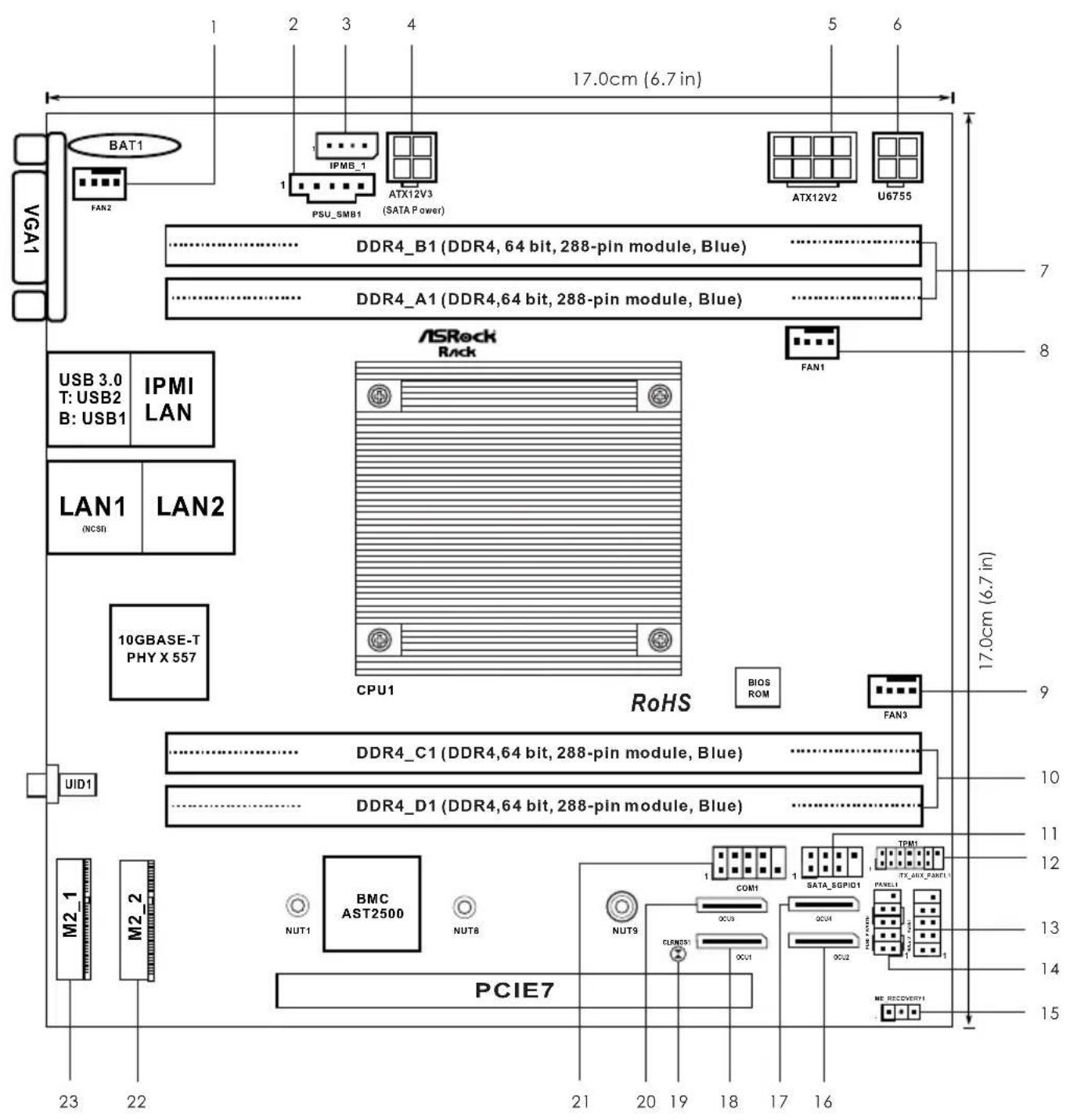
1.4 Motherboard Layout
text_image
17.0cm (6.7 in) BAT1 FAN2 IPME_1 PSU_SMB1 ATX12V3 (SATA Power) ATX12V2 U6755 DDR4_B1 (DDR4, 64 bit, 288-pin module, Blue) DDR4_A1 (DDR4,64 bit, 288-pin module, Blue) ASRock Rack USB 3.0 T: USB2 B: USB1 IPMI LAN LAN1 (NCSI) LAN2 10GBASE-T PHY X 557 CPU1 RoHS BIOS ROM FAN1 FAN3 DDR4_C1 (DDR4,64 bit, 288-pin module, Blue) DDR4_D1 (DDR4,64 bit, 288-pin module, Blue) PID1 M2_1 M2_2 NUT1 BMC AST2500 NUT8 PCIE7 23 22 21 20 19 18 17 16 15 14 13 12 11 10 9 8 7 17.0cm (6.7 in)No. Description
1 Rear Fan Connector (FAN2)
2 PSU SMBus (PSU_SMB1)
3 Intelligent Platform Management Bus header (IPMB_1)
4 SATA Power Connector (DC-IN Mode) (ATX12V3)**
5 ATX 12V Power Connector (ATX12V2)
6 ATX 12V Power Connector (U6755)**
7 2 x 288-pin DDR4 DIMM Slots (DDR4_A1, DDR4_B1)
8 CPU Fan Connector (FAN1)
9 Front Fan Connector (FAN3)
10 2 x 288-pin DDR4 DIMM Slots (DDR4_C1, DDR4_D1)
11 SATA SGPIO Connector (SATA_SGPIO1)
12 TPM Header (TPM1)
13 Auxiliary Panel Header (ITX_AUX_PANEL1)
14 System Panel Header (PANEL1)
15 ME Recovery Jumper (ME_RECOVERY1)
16 OCuLink x4 Connector (OCU2)
17 OCuLink x4 Connector (OCU4)
18 OCuLink x4 Connector (OCU1)
19 Clear CMOS Pad (CLRMOS1)
20 OCuLink x4 Connector (OCU3)
21 COM Port Header (COM1)
22 M.2 Socket (M2_2) (Type 2242)
23 M.2 Socket (M2_1) (Type 2280/22110)
*For DIMM installation and configuration instructions, please see p.13 (Installation of Memory Modules (DIMM)) for more details.
**Caution: Misconnection between the ATX12V3 and the U6755 connectors may permanently damage the motherboard.
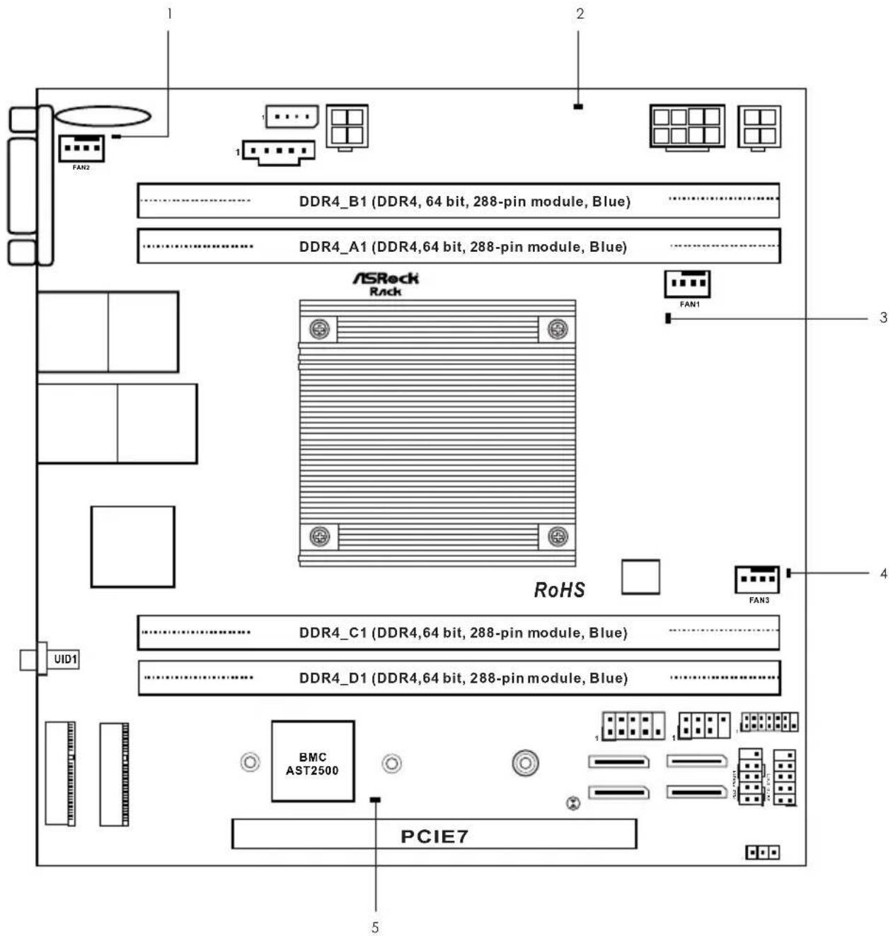
1.5 Onboard LED Indicators
text_image
FAN2 DDR4_B1 (DDR4, 64 bit, 288-pin module, Blue) DDR4_A1 (DDR4,64 bit, 288-pin module, Blue) ASRock Rack FAN1 RoHS FAN3 DDR4_C1 (DDR4,64 bit, 288-pin module, Blue) DDR4_D1 (DDR4,64 bit, 288-pin module, Blue) UID1 BMC AST2500 PCIE7 5 1 2 3 4No. Item Status Description
| 1 | LED_FAN2 | Amber | FAN2 failed |
| 2 | SB_PWR1 | Green | STB PWR ready |
| 3 | LED_FAN1 | Amber | FAN1 failed |
| 4 | LED_FAN3 | Amber | FAN3 failed |
| 5 | BMC_LED1 | Green | BMC heartbeat LED |
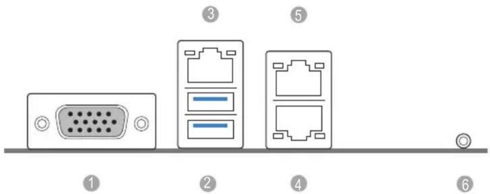
1.6 I/O Panel
text_image
Diagram showing six labeled electronic device ports: VGA, Ethernet ports, and a terminal with a circular connector.No. Description No. Description
1 VGA Port (VGA1) 4 10G LAN RJ-45 Port (LAN1)**
2 USB 3.0 Ports (USB3_12) 5 10G LAN RJ-45 Port (LAN2)**
3 Dedicated IPMI LAN Port* 6 UID Switch/LED (UID1)
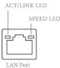
LAN Port LED Indications
*There are two LED next to the LAN port. Please refer to the table below for the LAN port LED indications.
text_image
ACT/LINK LED SPEED LED LAN PortDedicated IPMI LAN Port LED Indications
| Activity / Link LED Speed LED | |||
| Status Description Status Description | |||
| Off No Link Off | No Link | ||
| Blinking Yellow | Data Activity | Off | 10M bps connection |
| On | Link | Yellow | 100M bps connection |
| Green | 1G bps connection | ||
**There are two LEDs on each LAN port. Please refer to the table below for the LAN port LED indications.
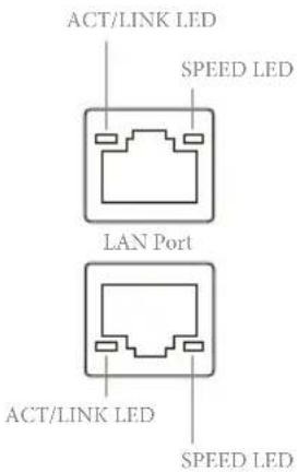
text_image
ACT/LINK LED SPEED LED LAN Port ACT/LINK LED SPEED LED10G LAN Port (LAN3, LAN4) LED Indications
| Activity / Link LED Speed LED | |||
| Status Description Status Description | |||
| Off No Link Off 100Mbps connection or | no link | ||
| Blinking Yellow | Data Activity | Yellow | 1Gbps connection |
| On | Link | Green | 10Gbps connection |
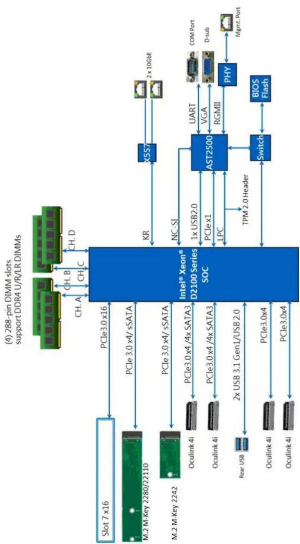
1.7 Block Diagram
flowchart
graph TD
    A["(4) 288-pin DIMM slots support DDR4 U/R/LR DIMMs"] --> B["Intel® Xeon® D2100 Series SOC"]
    B --> C["X557"]
    B --> D["AST2500"]
    B --> E["Switch"]
    B --> F["BIOS Flash"]
    B --> G["MCOS"]
    B --> H["COM Port"]
    B --> I["D-sub"]
    B --> J["Mgmt. Port"]
    B --> K["PCle3.0x4"]
    B --> L["PCle3.0x4/4x SATA3"]
    B --> M["PCle3.0x4/4x SATA3"]
    B --> N["PCle3.0x4/sSATA"]
    B --> O["PCle3.0x4/sSATA"]
    B --> P["PCle3.0x4/sSATA"]
    B --> Q["PCle3.0x4/sSATA"]
    B --> R["PCle3.0x4/sSATA"]
    B --> S["PCle3.0x4/sSATA"]
    B --> T["PCle3.0x4/sSATA"]
    B --> U["PCle3.0x4/sSATA"]
    B --> V["PCle3.0x4/sSATA"]
    B --> W["PCle3.0x4/sSATA"]
    B --> X["PCle3.0x4/sSATA"]
    B --> Y["PCle3.0x4/sSATA"]
    B --> Z["PCle3.0x4/sSATA"]
    B --> AA["PCle3.0x4/sSATA"]
    B --> AB["PCle3.0x4/sSATA"]
    B --> AC["PCle3.0x4/sSATA"]
    B --> AD["PCle3.0x4/sSATA"]
    B --> AE["PCle3.0x4/sSATA"]
    B --> AF["PCle3.0x4/sSATA"]
    B --> AG["PCle3.0x4/sSATA"]
    B --> AH["PCle3.0x4/sSATA"]
    B --> AI["PCle3.0x4/sSATA"]
    B --> AJ["PCle3.0x4/sSATA"]
    B --> AK["PCle3.0x4/sSATA"]
    B --> AL["PCle3.0x4/sSATA"]
    B --> AM["PCle3.0x4/sSATA"]
    B --> AN["PCle3.0x4/sSATA"]
    B --> AO["PCle3.0x4/sSATA"]
    B --> AP["PCle3.0x4/sSATA"]
    B --> AQ["PCle3.0x4/sSATA"]
    B --> AR["PCle3.0x4/sSATA"]
    B --> AS["PCle3.0x4/sSATA"]
    B --> AT["PCle3.0x4/sSATA"]
    B --> AU["PCle3.0x4/sSATA"]
    B --> AV["PCle3.0x4/sSATA"]
    B --> AW["PCle3.0x4/sSATA"]
    B --> AX["PCle3.0x4/sSATA"]
    B --> AY["PCle3.0x4/sSATA"]
    B --> AZ["PCle3.0x4/sSATA"]
    B --> BA["PCle3.0x4/sSATA"]
    B --> BB["PCle3.0x4/sSATA"]
    B --> BC["PCle3.0x4/sSATA"]
    B --> BD["PCle3.0x4/sSATA"]
    B --> BE["PCle3.0x4/sSATA"]
    B --> BF["PCle3.0x4/sSATA"]
    B --> BG["PCle3.0x4/sSATA"]
    B --> BH["PCle3.0x4/sSATA"]
    B --> BI["PCle3.0x4/sSATA"]
    B --> BJ["PCle3.0x4/sSATA"]
    B --> BK["PCle3.0x4/sSATA"]
    B --> BL["PCle3.0x4/sSATA"]
    B --> BM["PCle3.0x4/sSATA"]
    B --> BN["PCle3.0x4/sSATA"]
    B --> BO["PCle3.0x4/sSATA"]
    B --> BP["PCle3.0x4/sSATA"]
    B --> BQ["PCle3.0x4/sSATA"]
    B --> BR["PCle3.0x4/sSATA"]
    B --> BS["PCle3.0x4/sSATA"]
    B --> BT["PCle3.0x4/sSATA"]
    B --> BU["PCle3.0x4/sSATA"]
    B --> BV["PCle3.0x4/sSATA"]
    B --> BW["PCle3.0x4/sSATA"]
    B --> BX["PCle3.0x4/sSATA"]
    B --> BY["PCle3.0x4/sSATA"]
    B --> BZ["PCle3.0x4/sSATA"]
    B --> CA["PCle3.0x4/sSATA"]
    B --> CB["PCle3.0x4/sSATA"]
    B --> CC["PCle3.0x4/sSATA"]
    B --> CD["PCle3.0x4/sSATA"]
    B --> CE["PCle3.0x4/sSATA"]
    B --> CF["PCle3.0x4/sSATA"]
    B --> CG["PCle3.0x4/sSATA"]
    B --> CH["PCle3.0x4/sSATA"]
    B --> CI["PCle3.0x4/sSATA"]
    B --> CJ["PCle3.0x4/sSATA"]
    B --> CK["PCle3.0x4/sSATA"]
    B --> CL["PCle3.0x4/sSATA"]
    B --> CD
Chapter 2 Installation
This is a Mini-ITX form factor (6.7" x 6.7", 17.0 cm x 17.0 cm) motherboard. Before you install the motherboard, study the configuration of your chassis to ensure that the motherboard fits into it.

Make sure to unplug the power cord before installing or removing the motherboard. Failure to do so may cause physical injuries to you and damages to motherboard components.
2.1 Screw Holes
Place screws into the holes indicated by circles to secure the motherboard to the chassis.

Do not over-tighten the screws! Doing so may damage the motherboard.
2.2 Pre-installation Precautions
Take note of the following precautions before you install motherboard components or change any motherboard settings.
- Unplug the power cord from the wall socket before touching any components.
- To avoid damaging the motherboard's components due to static electricity, NEVER place your motherboard directly on the carpet or the like. Also remember to use a grounded wrist strap or touch a safety grounded object before you handle the components.
- Hold components by the edges and do not touch the ICs.
- Whenever you uninstall any component, place it on a grounded anti-static pad or in the bag that comes with the component.
- When placing screws into the screw holes to secure the motherboard to the chassis, please do not over-tighten the screws! Doing so may damage the motherboard.

Before you install or remove any component, ensure that the power is switched off or the power cord is detached from the power supply. Failure to do so may cause severe damage to the motherboard, peripherals, and/or components.
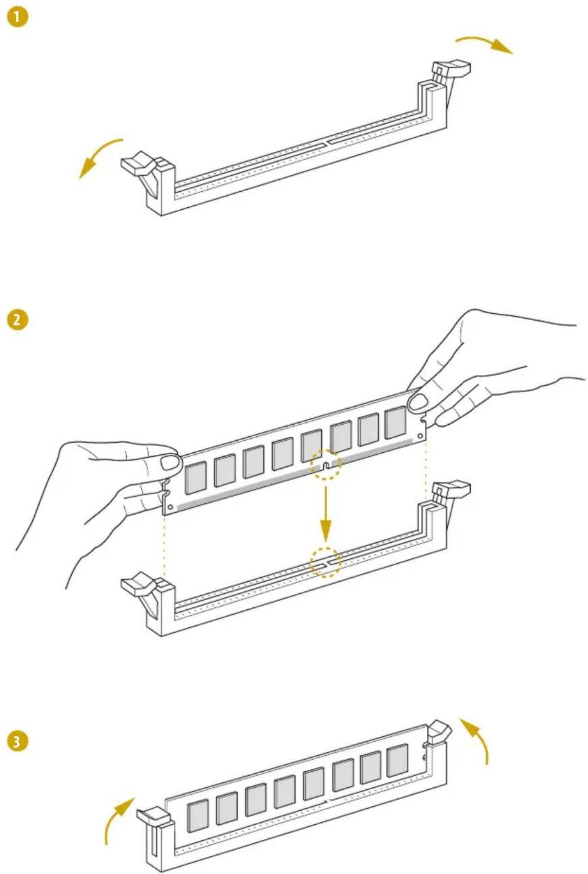
2.3 Installation of Memory Modules (DIMM)
This motherboard provides four 288-pin DDR4 (Double Data Rate 4) DIMM slots, and supports Dual / Quad Channel Memory Technology.

- For dual channel configuration, you always need to install identical (the same brand, speed, size and chip-type) DDR4 DIMM pairs.
- It is not allowed to install a DDR, DDR2 or DDR3 memory module into a DDR4 slot; otherwise, this motherboard and DIMM may be damaged.
- Please install the memory module on CH0_A1 for the first priority.
- To activate Dual Channel Memory Technology, please follow the "Dual Channel Memory Configuration" table below.
Dual / Quad Channel Memory Configuration
Priority
DDR4_A1
(Blue)
DDR4_B1
(Blue)
DDR4_C1
(Blue)
DDR4_D1
(Blue)
1 Populated Populated
2 Populated Populated Populated Populated
*Since installing three memory modules is NOT supported on this motherboard, we suggest not using this configuration.

The DIMM only fits in one correct orientation. It will cause permanent damage to the motherboard and the DIMM if you force the DIMM into the slot at incorrect orientation.
2.4 Expansion Slots (PCI Express Slots)
There is 1 PCI Express slots on this motherboard.
PCIE slot:
PCIE7 (PCIE 3.0 x16 slot) is used for PCI Express x16 lane width cards.
Installing an expansion card
Step 1. Before installing an expansion card, please make sure that the power supply is switched off or the power cord is unplugged. Please read the documentation of the expansion card and make necessary hardware settings for the card before you start the installation.
Step 2. Remove the system unit cover (if your motherboard is already installed in a chassis).
Step 3. Remove the bracket facing the slot that you intend to use. Keep the screws for later use.
Step 4. Align the card connector with the slot and press firmly until the card is completely seated on the slot.
Step 5. Fasten the card to the chassis with screws.
Step 6. Replace the system cover.
2.5 Jumper Setup
The illustration shows how jumpers are setup. When the jumper cap is placed on the pins, the jumper is "Short". If no jumper cap is placed on the pins, the jumper is "Open". The illustration shows a 3-pin jumper whose pin1 and pin2 are "Short" when a jumper cap is placed on these 2 pins.
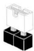
Short

Open
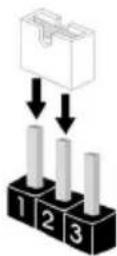
ME Recovery Jumper
(3-pin ME_RECOVERY1)
(see p.6, No. 15)
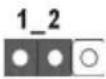
Normal Mode (Default)
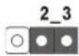
ME Recovery Mode
2.6 Onboard Headers and Connectors

Onboard headers and connectors are NOT jumpers. Do NOT place jumper caps over these headers and connectors. Placing jumper caps over the headers and connectors will cause permanent damage to the motherboard.
System Panel Header
(9-pin PANEL1)
(see p.6, No. 14)
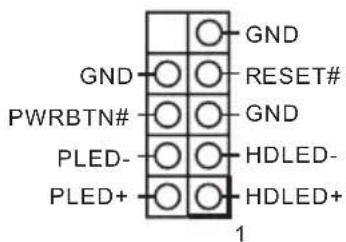
Connect the power switch, reset switch and system status indicator on the chassis to this header according to the pin assignments. Particularly note the positive and negative pins before connecting the cables.

PWRBTN (Power Switch):
Connect to the power switch on the chassis front panel. You may configure the way to turn off your system using the power switch.
RESET (Reset Switch):
Connect to the reset switch on the chassis front panel. Press the reset switch to restart the computer if the computer freezes and fails to perform a normal restart.
PLED (System Power LED):
Connect to the power status indicator on the chassis front panel. The LED is on when the system is operating. The LED is off when the system is in S4 sleep state or powered off (S5).
HDLED (Hard Drive Activity LED):
Connect to the hard drive activity LED on the chassis front panel. The LED is on when the hard drive is reading or writing data.
The front panel design may differ by chassis. A front panel module mainly consists of power switch, reset switch, power LED, hard drive activity LED, speaker and etc. When connecting your chassis front panel module to this header, make sure the wire assignments and the pin assignments are matched correctly.
Auxiliary Panel Header
(9-pin ITX_AUX_PAN-EL1)
(see p.6, No. 13)

text_image
LAN2_ACT# LED_PWR LED_PWR LAN1_ACT# SYSTEM_FAULT_LED_P SYSTEM_FAULT_LED_N GND CASEOPEN# 1This header supports multiple functions on the front panel, including front panel SMB, internet status indicator.
OCuLink Connectors
(OCU1)
(see p.6, No. 18)
(OCU2)
(see p.6, No. 16)
(OCU3)
(see p.6, No. 20)
(OCU4)
(see p.6, No. 17)
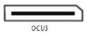

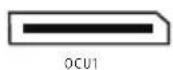

Please connect PCIE SSDs to these connectors.
TPM Header
(13-pin TPM1)
(see p.6, No. 11)
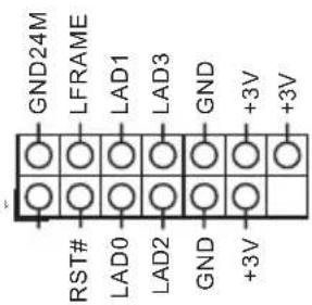
text_image
GND24M LFRAME LAD1 LAD3 GND +3V +3V RST# LAD0 LAD2 GND +3VThis connector supports
Trusted Platform Module (TPM) system, which can securely store keys, digital certificates, passwords, and data. A TPM system also helps enhance network security, protects digital identities, and ensures platform integrity.
PSU SMBus
(PSU__SMB1)
(see p.6, No. 2)
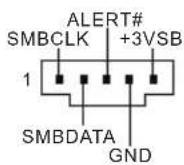
PSU SMBus monitors the
status of the power supply, fan and system temperature.
Front and Rear
Fan Connectors
(4-pin FAN2)
(see p.6, No. 1)
(4-pin FAN3)
(see p.6, No. 9)
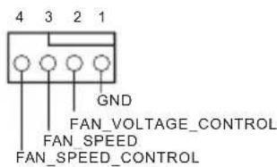
text_image
4 3 2 1 GND FAN_VOLTAGE_CONTROL FAN_SPEED FAN_SPEED_CONTROLPlease connect the fan cables to the fan connectors and match the black wire to the ground pin. All fans supports Fan Control.
CPU Fan Connectors
(4-pin FAN1)
(see p.6, No. 8)
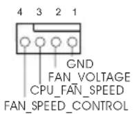
Please connect the CPU fan cable to the connector and match the black wire to the ground pin.
Though this motherboard provides a 4-Pin CPU fan (Quiet Fan) connector, 3-Pin CPU fans can still work successfully even without the fan speed control function. If you plan to connect a 3-Pin CPU fan to the CPU fan connector on this motherboard, please connect it to Pin 1-3.
*For more details, please refer to the Cooler QVL list on the ASRock Rack website.
Serial Port Header
(9-pin COM1)
(see p.6, No. 21)
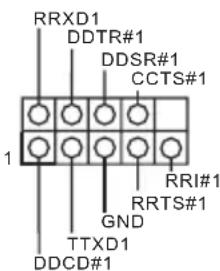
text_image
RRXD1 DDTR#1 DDSR#1 CCTS#1 RRI#1 RRTS#1 GND TTXD1 DDCD#1This COM header supports a serial port module.
Intelligent Platform
Management Bus header
(4-pin IPMB_1)
(see p.6, No. 3)
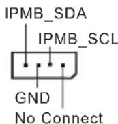
This 4-pin connector is used to provide a cabled baseboard or front panel connection for value added features and 3rd-party add-in cards, such as Emergency Management cards, that provide management features using the IPMB.
ATX 4-PIN Power
Connector
(4-pin U6755
(ATX 24pin-to-4pin)
(see p.6, No. 6)
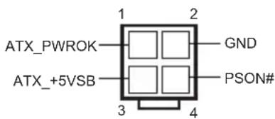
text_image
ATX_PWROK ATX_+5VSB 1 2 GND 3 4 PSON#The motherboard provides one 4-pin power/signal connector which is a required input for ATX power source.
When using ATX power, it is necessary to use a 24pin-to-4pin power cable to connect between the 24pin power connector of PSU and the U6755 connector on the motherboard for power supply and signal communication.
For DC-IN 12V application, it is not necessary to use this ATX 4-PIN power connector.
*Caution: Misconnection between the ATX12V3 and the U6755 connectors may permanently damage the motherboard.
SATA Power Connector
(DC-IN Mode)
(4-pin ATX12V3)
(see p.6, No. 4)
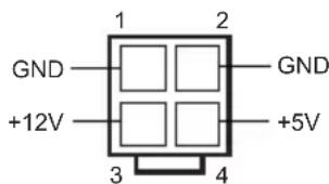
text_image
GND +12V 1 2 GND +5V 3 4Please use a SATA power cable to connect this SATA Power Connector and your SATA HDD for supplying power from the motherboard, when using DC-IN mode without SATA power supply.
*Caution: Misconnection between the ATX12V3 and the U6755 connectors may permanently damage the motherboard.
ATX 12V Power Connector (8-pin ATX12V2) (see p.6, No. 5)
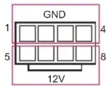
The motherboard provides one 8-pin 12V power connector which is a required input for either DC-IN 12V or ATX +12V power source.
When using ATX power, it is necessary to use a 24pin-to-4pin power cable to connect between the 24pin power connector of PSU and the U6755 connector on the motherboard for power supply and signal communication.
Clear CMOS Pads (CLR MOS1) (see p.6, No. 19)

This allows you to clear the data in CMOS. To clear CMOS, take out the CMOS battery and short the Clear CMOS Pad.
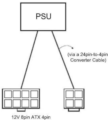
2.7 ATX PSU / DC-IN Power Connections
This motherboard supports both +12V DC and ATX power input. Please refer to the table below for the required connections between the motherboard and the power supply.
Connector DC-IN ATX PSU
12V 8pin O O
ATX 4pin X
O
(with the bundled ATX
24pin-to-4pin converter cable)
DC-IN
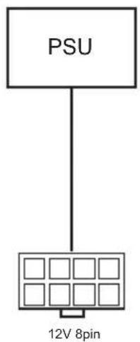
text_image
PSU 12V 8pinATX PSU
flowchart
graph TD
    A["PSU"] --> B["12V 8pin ATX 4pin"]
    A --> C["(via a 24pin-to-4pin Converter Cable)"]
The following diagram illustrates how to connect the bundled ATX 24pin-to-4pin converter cable.
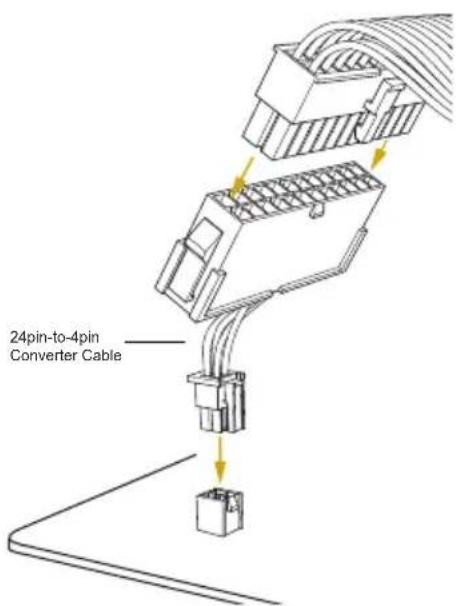
text_image
24pin-to-4pin Converter Cable2.8 Unit Identification purpose LED/Switch
With the UID button, You are able to locate the server you're working on from behind a rack of servers.
Unit Identification purpose LED/Switch (UID1)

When the UID button on the front or rear panel is pressed, the front/rear UID blue LED indicator will be turned on. Press the UID button again to turn off the indicator.
2.9 Driver Installation Guide
To install the drivers to your system, please insert the support CD to your optical drive first. Then, the drivers compatible to your system can be auto-detected and listed on the support CD driver page. Please follow the order from top to bottom to install those required drivers. Therefore, the drivers you install can work properly.
2.10 Dual LAN and Teaming Operation Guide
Dual LAN with Teaming enabled on this motherboard allows two single connections to act as one single connection for twice the transmission bandwidth, making data transmission more effective and improving the quality of transmission of distant images. Fault tolerance on the dual LAN network prevents network downtime by transferring the workload from a failed port to a working port.

The speed of transmission is subject to the actual network environment or status even with Teaming enabled.
Before setting up Teaming, please make sure whether your Switch (or Router) supports Teaming (IEEE 802.3ad Link Aggregation). You can specify a preferred adapter in Intel PROSet. Under normal conditions, the Primary adapter handles all non-TCP/IP traffic. The Secondary adapter will receive fallback traffic if the primary fails. If the Preferred Primary adapter fails, but is later restored to an active status, control is automatically switched back to the Preferred Primary adapter.
Step 1
From Device Manager, open the properties of a team.
Step 2
Click the Settings tab.
Step 3
Click the Modify Team button.
Step 4
Select the adapter you want to be the primary adapter and click the Set Primary button.
If you do not specify a preferred primary adapter, the software will choose an adapter of the highest capability (model and speed) to act as the default primary. If a failover occurs, another adapter becomes the primary. The adapter will, however, rejoin the team as a non-primary.
2.11 M.2\_SSD (NGFF) Module Installation Guide (M2\_1)
The M.2, also known as the Next Generation Form Factor (NGFF), is a small size and versatile card edge connector that aims to replace mPCIe and mSATA. The Ultra M.2 Socket supports a M.2 SATA3 6.0 Gb/s module or a M.2 PCI Express module up to Gen3 x4 (32Gb/s).
Installing the M.2\_SSD (NGFF) Module
natural_image
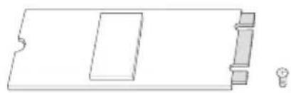
Pure technical line drawing of a rectangular component with internal cutouts and a small bulb at the bottom (no text or symbols)Step 1
Prepare a M.2_SSD (NGFF) module and the screw.
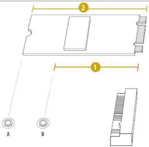
text_image
2 1 A BStep 2
Depending on the PCB type and length of your M.2_SSD (NGFF) module, find the corresponding nut location to be used.
No.12
Nut Location B A
PCB Length 8m 11cm
Module Type Type228 0 Type 22110

A

B

Step 3
Move the standoff based on the module type and length.
Skip Step 3 and 4 and go straight to Step 5 if you are going to use the default nut.
Otherwise, release the standoff by hand.

A

B

Step 4
Peel off the yellow protective film on the nut to be used. Hand tighten the standoff into the desired nut location on the motherboard.

A
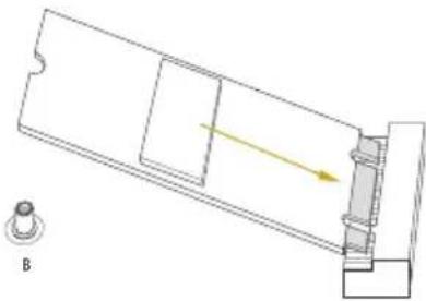
natural_image
Technical line drawing of a mechanical assembly with a yellow arrow indicating direction, no text or symbols present
A
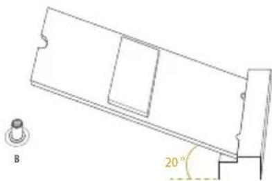
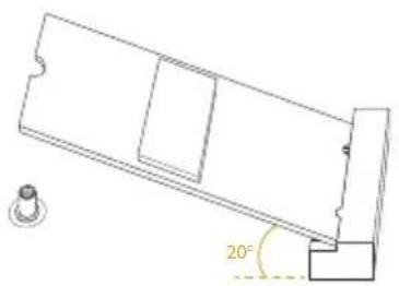
natural_image
Technical line drawing of a mechanical component with a 20-degree angle标注 (no text or symbols beyond the angle marker)
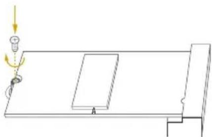
natural_image
Simple line drawing of a table with a hanging object and directional arrows, no text or symbols present.Step 5
Align and gently insert the M.2 (NGFF) SSD module into the M.2 slot. Please be aware that the M.2 (NGFF) SSD module only fits in one orientation.
Step 6
Tighten the screw with a screwdriver to secure the module into place.
Please do not overtighten the screw as this might damage the module.
2.12 M.2\_SSD (NGFF) Module Installation Guide (M2\_2)
The M.2, also known as the Next Generation Form Factor (NGFF), is a small size and versatile card edge connector that aims to replace mPCIe and mSATA. This M.2_SSD (NGFF) Socket 3 can accommodate a M.2 PCI Express module up to Gen3 x4 (32 Gb/s) only.
Installing the M.2_SSD (NGFF) Module
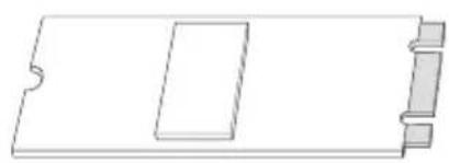
natural_image
Pure technical line drawing of a rectangular component with notches and side brackets (no text or symbols)Step 1
Prepare a M.2_SSD (NGFF) module and the screw.
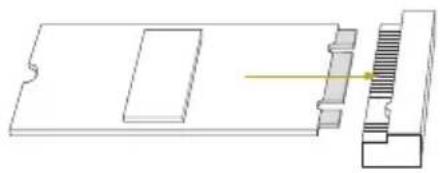
natural_image
Technical line drawing of a mechanical component with a 20-degree angle标注 (no text or symbols beyond the angle marker)Step 2
Gently insert the M.2 (NGFF) SSD module into the M.2 slot. Please be aware that the M.2 (NGFF) SSD module only fits in one orientation.
natural_image
Pure mechanical assembly diagram showing a rectangular block with internal components and a yellow arrow indicating direction (no text or symbols)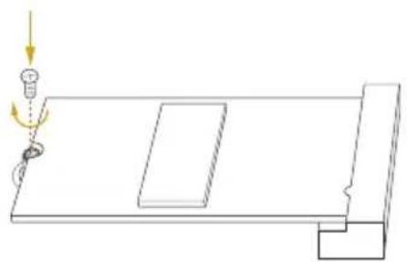
natural_image
Simple line drawing of a table with a light bulb and a hanging object, no text or symbols presentStep 3
Tighten the screw with a screwdriver to secure the module into place. Please do not overtighten the screw as this might damage the module.
M.2\_SSD (NGFF) Module Support List
For the latest updates of M.2_SSD (NFGG) module support list, please visit our website for details: http://www.asrockrack.com
Chapter 3 UEFI Setup Utility
3.1 Introduction
This section explains how to use the UEFI SETUP UTILITY to configure your system. The UEFI chip on the motherboard stores the UEFI SETUP UTILITY. You may run the UEFI SETUP UTILITY when you start up the computer. Please press during the Power-On-Self-Test (POST) to enter the UEFI SETUP UTILITY; otherwise, POST will continue with its test routines.
If you wish to enter the UEFI SETUP UTILITY after POST, restart the system by pressing

Because the UEFI software is constantly being updated, the following UEFI setup screens and descriptions are for reference purpose only, and they may not exactly match what you see on your screen.
3.1.1 UEFI Menu Bar
The top of the screen has a menu bar with the following selections:
Item Description
| Main To set up the system time/date information | |
| Advanced To set up the advanced UEFI features | |
| Security To set up the security features | |
| Boot | To set up the default system device to locate and load the Operating System |
| Event Logs For event log configuration | |
| Server Mgmt To manage the server | |
| Exit To exit the current screen or the UEFI SETUP UTILITY | |
Use <<--> key or <--> key to choose among the selections on the menu bar, and then press
3.1.2 Navigation Keys
Please check the following table for the function description of each navigation key.
Navigation Key(s) Function Description
← / Moves cursor left or right to select Screens
↑ / Moves cursor up or down to select items
+ / - To change option for the selected items
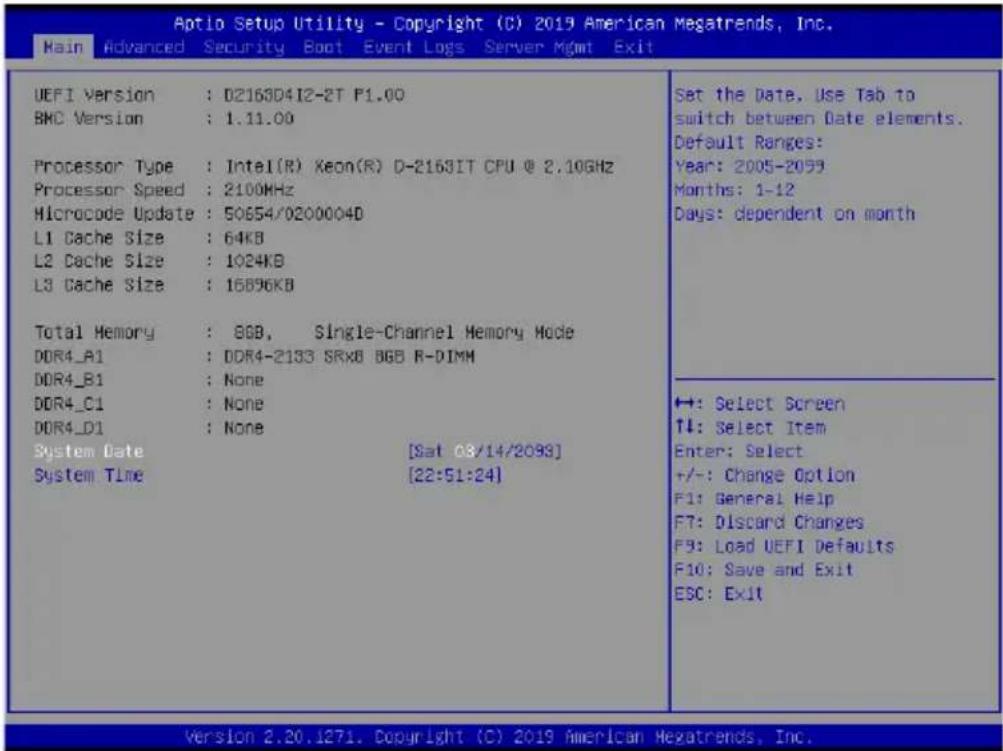
3.2 Main Screen
Once you enter the UEFI SETUP UTILITY, the Main screen will appear and display the system overview. The Main screen provides system overview information and allows you to set the system time and date.
text_image
Aptio Setup Utility - Copyright (C) 2019 American Megatrends, Inc. Main Advanced Security Boot Event Logs Server Mgmt Exit UEFI Version : D2163D4I2-2T F1.00 BMC Version : 1.11.00 Processor Type : Intel(R) Keon(R) D-2163IT CPU @ 2.10GHz Processor Speed : 2100MHz Microcode Update : 50654/0200004D L1 Cache Size : 64KB L2 Cache Size : 1024KB L3 Cache Size : 16896KB Total Memory : 8GB, Single-Channel Memory Mode DDR4_A1 : DDR4-2133 SRx8 BGB R-DIMM DDR4_B1 : None DDR4_C1 : None DDR4_D1 : None System Date [Sat 03/14/2098] System Time [22:51:24] Set the Date, Use Tab to switch between Date elements. Default Ranges: Year: 2005-2099 Months: 1-12 Days: dependent on month ↔: Select Screen ↑↓: Select Item Enter: Select +/-: Change Option F1: General Help F7: Discard Changes F8: Load UEFI Defaults F10: Save and Exit ESC: Exit Version 2.20.1271. Copyright (C) 2019 American Megatrends, Inc.3.3 Advanced Screen
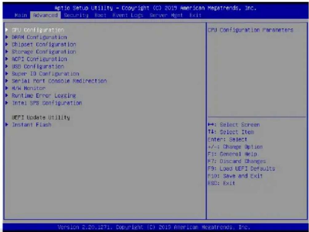
In this section, you may set the configurations for the following items: CPU Configuration, DRAM Configuration, Chipset Configuration, Storage Configuration, ACPI Configuration, USB Configuration, Super IO Configuration, Serial Port Console Redirection, H/W Monitor, Runtime Error Logging, Intel SPS Configuration and Instant Flash.
text_image
Aptio Setup Utility - Copyright (C) 2019 American Megatrends, Inc. Main Advanced Security Boot Event Logs Server Mgmt Exit ▶ CPU Configuration ▶ DRAM Configuration ▶ Chipset Configuration ▶ Storage Configuration ▶ ACPI Configuration ▶ USB Configuration ▶ Super ID Configuration ▶ Serial Port Console Redirection ▶ H/W Monitor ▶ Runtime Error Logging ▶ Intel SPS Configuration UEFI Update Utility ▶ Instant Flash CPU Configuration Parameters +: Select Screen T↓: Select Item Enter: Select +/-: Change Option F1: General Help F7: Discard Changes F9: Load UEFI Defaults F10: Save and Exit ESC: Exit Version 2.20.1271. Copyright (C) 2019 American Megatrends, Inc.
Setting wrong values in this section may cause the system to malfunction.
3.3.1 CPU Configuration
text_image
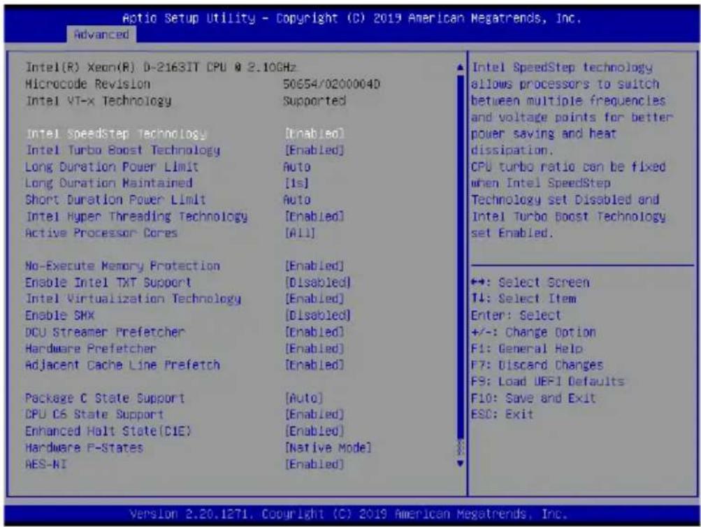
Aptio Setup Utility - Copyright (C) 2019 American Megatrends, Inc. Advanced Intel(R) Xeon(R) D-2163IT CPU @ 2.10GHz Microcode Revision 50654/0200004D Intel VT-x Technology Supported Intel speedstep technology [Enabled] Intel Turbo Boost Technology [Enabled] Long Duration Power Limit Auto Long Duration Maintained [Is] Short Duration Power Limit Auto Intel Hyper Threading Technology [Enabled] Active Processor Cores [All] No-Execute Memory Protection [Enabled] Enable Intel TXT Support [Disabled] Intel Virtualization Technology [Enabled] Enable SMX [Disabled] DCU Streamer Prefetcher [Enabled] Hardware Prefetcher [Enabled] Adjacent Cache Line Prefetch [Enabled] Package C State Support [Auto] CPU C6 State Support [Enabled] Enhanced Halt State(CIE) [Enabled] Hardware P-States [Native Mode] AES-NI [Enabled] Intel SpeedStep technology allows processors to switch between multiple frequencies and voltage points for better power saving and heat dissipation. CPU turbo ratio can be fixed when Intel SpeedStep Technology set Disabled and Intel Turbo Boost Technology set Enabled. ◆: Select Screen ↑: Select Item Enter: Select +/-: Change Option F1: General Help F7: Discard Changes F9: Load UEFI Defaults F10: Save and Exit ESC: Exit Version 2.20.1271, Copyright (C) 2019 American Megatrends, Inc.Intel SpeedStep Technology
Intel SpeedStep technology allows processors to switch between multiple frequencies and voltage points for better power saving and heat dissipation. CPU turbo ratio can be fixed when Intel SpeedStep Technology set Disabled and Intel Turbo Boost Technology set Enabled.

Please note that enabling this function may reduce CPU voltage and lead to system stability or compatibility issues with some power supplies. Please set this item to [Disabled] if above issues occur.
Intel Turbo Boost Technology
Intel Turbo Boost Technology enables the processor to run above its base operating frequency when the operating system requests the highest performance state.
Long Duration Power Limit
Configure Package Power Limit 1 in watts. When the limit is exceeded, the CPU ratio will be lowered after a period of time. A lower limit can protect the CPU and save power, while a higher limit may improve performance.
Long Duration Maintained
Configure the period of time until the CPU ratio is lowered when the Long Duration Power
Limit is exceeded.
Short Duration Power Limit
Configure Package Power Limit 2 in watts. When the limit is exceeded, the CPU ratio will be lowered immediately. A lower limit can protect the CPU and save power, while a higher limit may improve performance.
Intel Hyper Threading Technology
Intel Hyper Threading Technology allows multiple threads to run on each core, so that the overall performance on threaded software is improved.
Active Processor Cores
Select the number of cores to enable in each processor package.
No-Execute Memory Protection
Processors with No-Execution Memory Protection Technology may prevent certain classes of malicious buffer overflow attacks.
Enable Intel TXT Support
Enables Intel Trusted Execution Technology Configuration.
Intel Virtualization Technology
Intel Virtualization Technology allows a platform to run multiple operating systems and applications in independent partitions, so that one computer system can function as multiple virtual systems.
Enable SMX
Use this item to enable Safer Mode Extensions.
DCU Streamer Prefetcher
DCU streamer prefetcher is an L1 data cache prefetcher (MSR 1A4h [2]).
Hardware Prefetcher
Automatically prefetch data and code for the processor. Enable for better performance.
Adjacent Cache Line Prefetch
Automatically prefetch the subsequent cache line while retrieving the currently requested cache line. Enable for better performance.
Package C State Support
Enable CPU, PCIe, Memory, Graphics C State Support for power saving.
CPU C6 State Support
Enable C6 deep sleep state for lower power consumption.
Enhanced Halt State(C1E)
Enable Enhanced Halt State (C1E) for lower power consumption.
Hardware P-States
Disable: Hardware chooses a P-state based on OS Request (Legacy P-States)
Native Mode: Hardware chooses a P-state based on OS guidance
Out of Band Mode: Hardware autonomously chooses a P-state (no OS guidance)
AES-NI
Use this item to enable or disable AES-NI support.
CPU Thermal Throttling
Enable CPU internal thermal control mechanisms to keep the CPU from overheating.
3.3.2 DRAM Configuration
| Aptio Setup Utility - Copyright (C) 2019 American Megatrends, Inc. Advanced | ||
| Enforce POR DRAM Frequency | [Enforce POR] [Auto] | Enforce POR - Enforces Plan Of Record restrictions for DDR4 frequency and voltage programming. Disable - Disables this feature. Auto - Sets it to the MRC default setting; current default is Enable. |
| Channel Interleaving Rank Interleaving Mirror Mode Memory Rank Sparing | [Auto] [Auto] [Disabled] [Disabled] | |
| +:-: Select Screen ↑↓: Select Item Enter: Select +/-: Change Option F1: General Help F7: Discard Changes F3: Load UEFI Defaults F10: Save and Exit ESC: Exit | ||
Enforce POR
Enforce POR - Enforces Plan Of Record restrictions for DDR4 frequency and voltage programming.
Disable - Disables this feature.
DRAM Frequency
If [Auto] is selected, the motherboard will detect the memory module(s) inserted and assign the appropriate frequency automatically.
Channel Interleaving
Select to configure Channel Interleaving settings.
Rank Interleaving
Select to configure Rank Interleaving settings.
Mirror Mode
Mirror Mode will set entire 1LM/2LM memory in system to be mirrored, consequently reducing the memory capacity by half. Mirror Enable will disable XPT Prefetch.
Memory Rank Sparing
Enable or disable Memory Rank Sparing.
3.3.3 Chipset Configuration
text_image
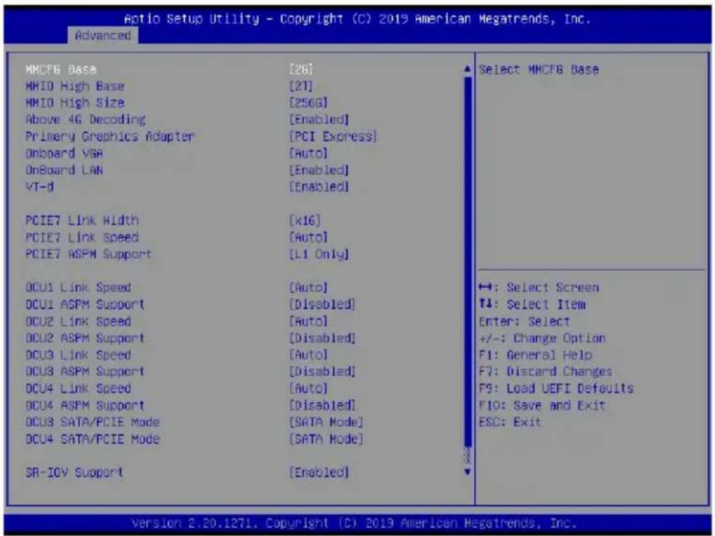
Optio Setup Utility - Copyright (C) 2019 American Megatrends, Inc. Advanced MMCFG Base [26] MMIO High Base [2T] MMIO High Size [256G] Above 4G Decoding [Enabled] Primary Graphics Adapter [PCI Express] Onboard VGA [Auto] OnBoard LAN [Enabled] VT-d [Enabled] PCIE7 Link Width [x16] PCIE7 Link Speed [Auto] PCIE7 ASPM Support [L1 Only] DCU1 Link Speed [Auto] DCU1 ASPM Support [Disabled] DCU2 Link Speed [Auto] DCU2 ASPM Support [Disabled] DCU3 Link Speed [Auto] DCU3 ASPM Support [Disabled] DCU4 Link Speed [Auto] DCU4 ASPM Support [Disabled] DCU3 SATA/PCIE Mode [SATA Mode] DCU4 SATA/PCIE Mode [SATA Mode] SR-IOV Support [Enabled] Select MMCFG Base →: Select Screen ↑: Select Item Enter: Select +/-: Change Option F1: General Help F7: Discard Changes F9: Load UEFI Defaults F10: Save and Exit ESC: Exit Version 2.20.1271, Copyright (C) 2019 American Megatrends, Inc.MMCFG Base
Use this item to select MMCFG Base.
MMIO High Base
Use this item to select MMIO High Base.
MMIO High Size
Use this item to select MMIO High Size.
Above 4G Decoding
Enable or disable 64bit capable Devices to be decoded in Above 4G Address Space (only if the system supports 64 bit PCI decoding).
Primary Graphics Adapter
If PCI Express graphics card is installed on the motherboard, you may use this option to select PCI Express or Onboard VGA as the primary graphics adapter.
*If no PCI Express graphics card is installed, [Onboard VGA] is the default graphics adapter. There is no screen on monitor even if a HDMI display is connected. Select [Onboard Hdmi] instead to use HDMI as output source.
Onboard VGA
Use this to enable or disable the Onboard VGA function. The default value is [Auto].
*This item is not available when the Primary Graphic Adapter is set to [Onboard VGA].
Onboard LAN
Use this to enable or disable the Onboard LAN function. The default value is [Auto].
VT-d
Intel(R) Virtualization Technology for Directed I/O helps your virtual machine monitor better utilize hardware by improving application compatibility and reliability, and providing additional levels of manageability, security, isolation, and I/O performance.
PCIE7 Link Width
This allows you to select PCIE7 Link Width. The default value is [Auto].
PCIE7 Link Speed
This allows you to select PCIE7 Link Speed. The default value is [Auto].
PCIE7 ASPM Support
This option enables or disables the ASPM support for all CPU downstream devices.
OCU1 Link Speed
This allows you to select OCU1Link Speed. The default value is [Auto].
OCU1 ASPM Support
This option enables or disables the ASPM support for all CPU downstream devices.
OCU2 Link Speed
This allows you to select OCU2Link Speed. The default value is [Auto].
OCU2 ASPM Support
This option enables or disables the ASPM support for all CPU downstream devices.
OCU3 Link Speed
This allows you to select OCU3 Link Speed. The default value is [Auto].
OCU3 ASPM Support
This option enables or disables the ASPM support for all CPU downstream devices.
OCU4 Link Speed
This allows you to select OCU4 Link Speed. The default value is [Auto].
OCU4 ASPM Support
This option enables or disables the ASPM support for all CPU downstream devices.
OCU3 SATA/PCIE Mode
This allows you to select OCU3 SATA/PCIE Mode. The default value is [SATA Mode].
OCU4 SATA/PCIE Mode
This allows you to select OCU4 SATA/PCIE Mode. The default value is [SATA Mode].
SR-IOV Support
If system has SR-IOV capable PCIe Devices, this option Enables or Disables Single Root IO Virtualization Support.
Restore AC Power Loss
This allows you to set the power state after a power failure. If [Power Off] is selected, the power will remain off when the power recovers. If [Power On] is selected, the system will start to boot up when the power recovers.
Restore AC Power Current State
This allows you to restore AC Power Current State.
3.3.4 Storage Configuration
text_image
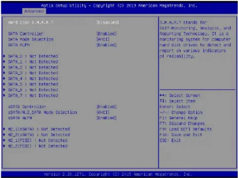
Aptio Setup Utility - Copyright (C) 2019 American Megatrends, Inc. Advanced Hard Disk S.M.A.R.T [Disabled] SATA Controller [Enabled] SATA Mode Selection [AHCI] SATA ALPM [Enabled] ▶ SATA_0 : Not Detected ▶ SATA_1 : Not Detected ▶ SATA_2 : Not Detected ▶ SATA_3 : Not Detected ▶ SATA_4 : Not Detected ▶ SATA_5 : Not Detected ▶ SATA_6 : Not Detected ▶ SATA_7 : Not Detected sSATA Controller [Enabled] sSATA/H.2_SATA Mode Selection [AHCI] sSATA ALPM [Enabled] ▶ H2_1(sSATA) : Not Detected ▶ H2_2(sSATA) : Not Detected ▶ H2_1(PCIE) : Not Detected ▶ H2_2(PCIE) : Not Detected S.M.A.R.T stands for Self-Monitoring, Analysis, and Reporting Technology. It is a monitoring system for computer hard disk drives to detect and report on various indicators of reliability. ↔: Select Screen ↑↓: Select Item Enter: Select +/-: Change Option F1: General Help F7: Discard Changes F9: Load UEFI Defaults F10: Save and Exit ESC: Exit Version 2.20.1271. Copyright (C) 2019 American Megatrends, Inc.Hard Disk S.M.A.R.T.
S.M.A.R.T stands for Self-Monitoring, Analysis, and Reporting Technology. It is a monitoring system for computer hard disk drives to detect and report on various indicators of reliability.
SATA Controller
Use this item to enable or disable SATA Controllers.
SATA Mode Selection
Identify the SATA port is connected to Solid State Drive or Hard Disk Drive. Press
SATA ALPM
Use this item to enable or disable Support Aggressive Link Power Management.
SATA Port 0 / 1 / 2 / 3 / 4 / 5 / 6 / 7
Depending on how many SATA ports you have, you will see SATA_x (x means number) listed on the screen, with its status indicated as SATA device [(Model Name)] or [Not Detected].
sSATA Controller
Use this item to enable or disable sSATA Controllers.
sSATA/M.2\_SATA Mode Selection
Identify the sSATA port is connected to Solid State Drive or Hard Disk Drive. Press
sSATA ALPM
Use this item to enable or disable Support Aggressive Link Power Management.
M2\_1(sSATA) / M2\_2(sSATA) / M2\_1(PCIE) / M2\_2(PCIE)
Depending on how many SATA ports you have, you will see sSATA_x (x means number) listed on the screen, with its status indicated as sSATA device [(Model Name)] or [Not Detected].
3.3.5 ACPI Configuration
text_image
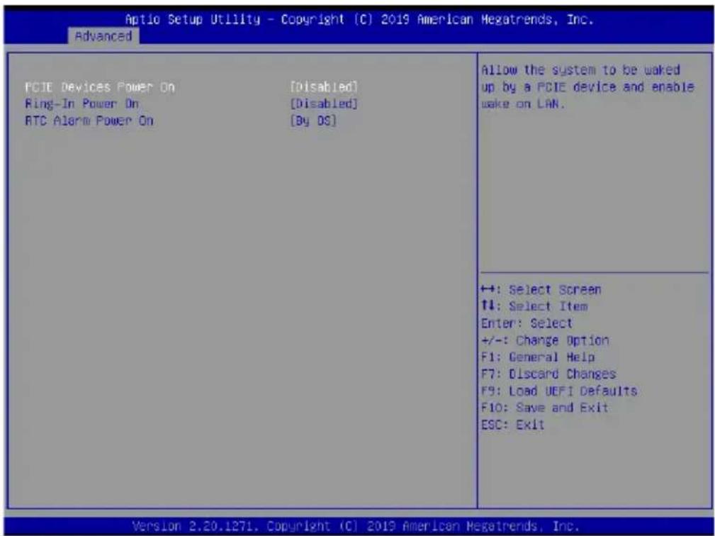
Aptio Setup Utility - Copyright (C) 2019 American Megatrends, Inc. Advanced PCIE Devices Power On [Disabled] Ring-In Power On [Disabled] RTC Alarm Power On [By DS] Allow the system to be woked up by a PCIE device and enable wake on LAN. ++: Select Screen ↑↓: Select Item Enter: Select +/-: Change Option F1: General Help F7: Discard Changes F9: Load UEFI Defaults F10: Save and Exit ESC: Exit Version 2.20.1271. Copyright (C) 2019 American Megatrends, Inc.PCIE Devices Power On
Allow the system to be waked up by a PCIE device and enable wake on LAN.
Ring-In Power On
Use this item to enable or disable Ring-In signals to turn on the system from the powersoft-off mode.
RTC Alarm Power On
Allow the system to be waked up by the real time clock alarm. Set it to By OS to let it be handled by your operating system.
3.3.6 USB Configuration
text_image
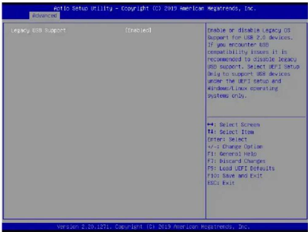
Aptio Setup Utility - Copyright (C) 2019 American Megatrends, Inc. Advanced Legacy USB Support [Enabled] Enable or disable Legacy OS Support for USB 2.0 devices. If you encounter USB compatibility issues it is recommended to disable legacy USB support. Select UEFI Setup Only to support USB devices under the UEFI setup and Windows/Linux operating systems only. +: Select Screen +: Select Item Enter: Select +/-: Change Option F1: General Help F7: Discard Changes F9: Load UEFI Defaults F10: Save and Exit ESC: Exit Version 2.20.127L. Copyright (C) 2019 American Megatrends, Inc.Legacy USB Support
Enable or disable Legacy OS Support for USB 2.0 devices. If you encounter USB compatibility issues it is recommended to disable legacy USB support.
Select UEFI Setup Only to support USB devices under the UEFI setup and Windows/Linux operating systems only.
3.3.7 Super IO Configuration
text_image
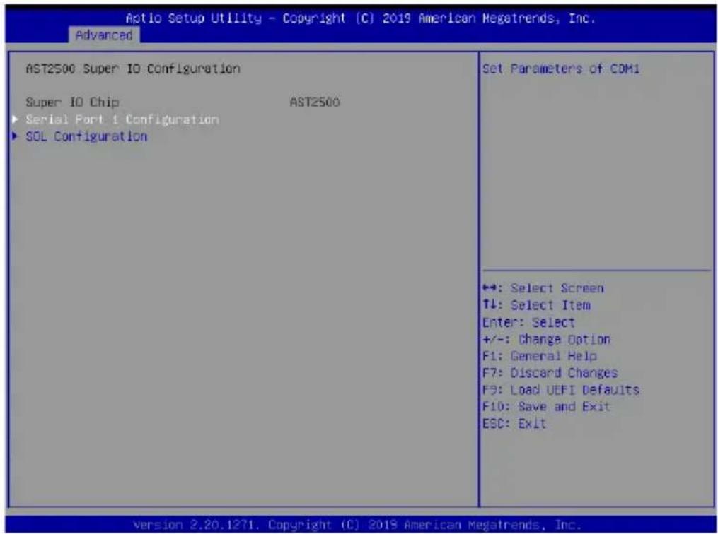
Aptio Setup Utility - Copyright (C) 2019 American Megatrends, Inc. Advanced AST2500 Super IO Configuration Super IO Chip AST2500 ► Serial Port 1 Configuration ► SOL Configuration Set Parameters of COM1 +: Select Screen T↓: Select Item Enter: Select +/-: Change Option F1: General Help F7: Discard Changes F9: Load UEFI Defaults F10: Save and Exit ESC: Exit Version 2.20.1271. Copyright (C) 2019 American Megatrends, Inc.Serial Port 1 Configuration
Use this item to set parameters of COM1.
Serial Port
Use this item to enable or disable the serial port (COM).
Change Settings
Use this item to select an optimal setting for Super IO device.
SOL Configuration
Use this item to set parameters of SOL.
Serial Port
Use this item to enable or disable the serial port (COM).
Change Settings
Use this item to select an optimal setting for Super IO device.
3.3.8 Serial Port Console Redirection
text_image
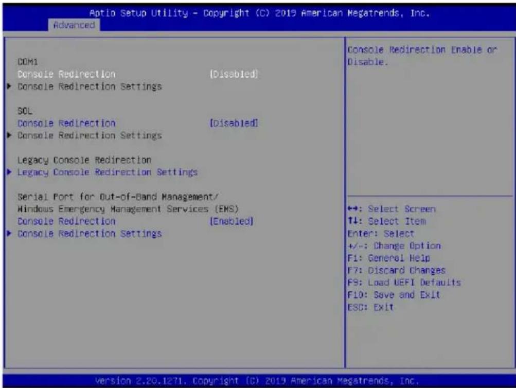
Aptio Setup Utility - Copyright (C) 2019 American Megatrends, Inc. Advanced COM1 Console Redirection (Disabled) ► Console Redirection Settings SOL Console Redirection [Disabled] ► Console Redirection Settings Legacy Console Redirection ► Legacy Console Redirection Settings Serial Port for Out-of-Band Management/ Windows Emergency Management Services (EMS) Console Redirection (Enabled) ► Console Redirection Settings Console Redirection Enable or Disable. +: Select Screen ↑↓: Select Item Enter: Select +/-: Change Option F1: General Help F7: Discard Changes F9: Load UEFI Defaults F10: Save and Exit ESC: Exit Version 2.20.1271. Copyright (C) 2019 American Megatrends, Inc.COM 1 / SOL
Console Redirection
Use this option to enable or disable Console Redirection. If this item is set to Enabled, you can select a COM Port to be used for Console Redirection.
Console Redirection Settings
Use this option to configure Console Redirection Settings, and specify how your computer and the host computer to which you are connected exchange information. Both computers should have the same or compatible settings.
Terminal Type
Use this item to select the preferred terminal emulation type for out-of-band management.
| Option Description | |
| VT100 ASCII character set | |
| VT100+ Extended VT100 that supports color and function keys | |
| VT-U TF8 UTF8 encoding is used to map Unicode chars onto 1 or more bytes | |
| ANSI Extended ASCII character set |
Bits Per Second
Use this item to select the serial port transmission speed. The speed used in the host computer and the client computer must be the same. Long or noisy lines may require lower transmission speed. The options include [9600] , [19200] , [38400] , [57600] and [115200] .
Data Bits
Use this item to set the data transmission size. The options include [7] and [8] (Bits).
Parity
Use this item to select the parity bit. The options include [None], [Even], [Odd], [Mark] and [Space]. A parity bit can be sent with the data bits to detect some transmission errors. Mark and Space Parity do not allow for error detection. They can be used as an additional data bit.
Even: parity bit is 0 if the num of 1's in the data bits is even.
Odd: parity bit is 0 if num of 1's in the data bits is odd.
Mark: parity bit is always 1.
Space: Parity bit is always 0.
Stop Bits
The item indicates the end of a serial data packet. The standard setting is [1] Stop Bit. Select [2] Stop Bits for slower devices.
Flow Control
Use this item to set the flow control to prevent data loss from buffer overf low. When sending data, if the receiving buffers are full, a "stop" signal can be sent to stop the data flow. Once the buffers are empty, a "start" signal can be sent to restart the flow. Hardware flow uses two wires to send start/stop signals. The options include [None] and [Hardware RTS/CTS].
VT-UTF8 Combo Key Support
Use this item to enable or disable the VT-UTF8 Combo Key Support for ANSI/VT100 terminals.
Recorder Mode
Use this item to enable or disable Recorder Mode to capture terminal data and send it as text messages.
Resolution 100x31
Use this item to enable or disable extended terminal resolution support.
Putty Keypad
Use this item to select Function Key and Keypad on Putty.
Legacy Console Redirection
Legacy Console Redirection Settings
Use this option to configure Legacy Console Redirection Settings, and specify how your
computer and the host computer to which you are connected exchange information.
Redirection COM Port
Select a COM port to display redirection of Legacy OS and Legacy OPROM Messages.
Resolution
On Legacy OS, the Number of Rows and Columns supported redirection.
Redirect After POST
When Bootloader is selected, then Legacy Console Redirection is disabled before booting to legacy OS. When Always Enable is selected, then Legacy Console Redirection is enabled for legacy OS. Default setting for this option is set to Always Enable.
Serial Port for Out-of-Band Management/Windows Emergency Management Services (EMS)
Console Redirection
Use this option to enable or disable Console Redirection. If this item is set to Enabled, you can select a COM Port to be used for Console Redirection.
Console Redirection Settings
Use this option to configure Console Redirection Settings, and specify how your computer and the host computer to which you are connected exchange information.
Out-of-Band Mgmt Port
Microsoft Windows Emergency Management Services (EMS) allows for remote management of a Windows Server OS through a serial port.
Terminal Type
Use this item to select the preferred terminal emulation type for out-of-band management. It is recommended to select [VT-UTF8].
| Option Description | |
| VT100 ASCII character set | |
| VT100+ Extended VT100 that supports color and function keys | |
| VT-U TF8 UTF8 encoding is used to map Unicode chars onto 1 or more bytes | |
| ANSI Extended ASCII character set |
Bits Per Second
Use this item to select the serial port transmission speed. The speed used in the host computer and the client computer must be the same. Long or noisy lines may require lower transmission speed. The options include [9600] , [19200] , [57600] and [115200] .
Flow Control
Use this item to set the flow control to prevent data loss from buffer overflow. When sending data, if the receiving buffers are full, a "stop" signal can be sent to stop the data flow. Once the buffers are empty, a "start" signal can be sent to restart the flow. Hardware flow uses two wires to send start/stop signals. The options include [None], [Hardware RTS/
CTS], and [Software Xon/Xoff].
Data Bits
Parity
Stop Bits
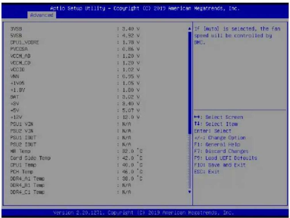
3.3.9 H/W Monitor
In this section, it allows you to monitor the status of the hardware on your system, including the parameters of the CPU temperature, motherboard temperature, CPU fan speed, chassis fan speed, and the critical voltage.
text_image
Aptio Setup Utility - Copyright (C) 2019 American Megatrends, Inc. Advanced 3VSB : 3.40 V 5VSB : 4.92 V CPU1_VCORE : 1.78 V PVCCSA : 0.86 V VCCH_AB : 1.20 V VCCH_CD : 1.20 V VCCIO : 1.02 V YNN : 0.95 V +1VOS : 1.05 V +1.0V : 1.80 V BAT : 3.02 V +8V : 3.40 V +5V : 5.07 V +12V : 12.0 V PSU1 VIN : N/A PSU2 VIN : N/A PSU1 IOUT : N/A PSU2 IOUT : N/A HB Temp : 32.0 °C Card Side Temp : 42.0 °C CPU1 Temp : 40.0 °C PCH Temp : 46.0 °C DDR4_A1 Temp : 38.0 °C DDR4_B1 Temp : N/A DDR4_C1 Temp : N/A If [Auto] is selected, the fan speed will be controlled by BMC. ↔: Select Screen T1: Select Item Enter: Select +/-: Change Option F1: General Help F7: Discard Changes F9: Load UEFI Defaults F10: Save and Exit ESO: Exit Version 2.20.1271, Copyright (C) 2019 American Megatrends, Inc.Fan Control
If [Auto] is selected, the fan speed will controlled by BMC.
If [Manual] is selected, configure the items below.
FAN1
This allows you to set the CPU fan1's speed. The default value is [Smart Fan].
FAN2
This allows you to set the rear fan1's speed. The default value is [Smart Fan].
FAN3
This allows you to set the front fan1's speed. The default value is [Smart Fan].
Smart Fan Control
This allows you to set the Smart fan's level speed.
Smart Fan Duty Control
Smart Fan Duty x (x means 1 to 11 stage)
This allows you to set duty cycle for each stage.
Smart Fan Temp Control
Smart Fan Temp x (x means 1 to 11 stage)
This allows you to set temperature for each stage.
Watch Dog Timer
This allows you to enable or disable the Watch Dog Timer. The default value is [Disabled].
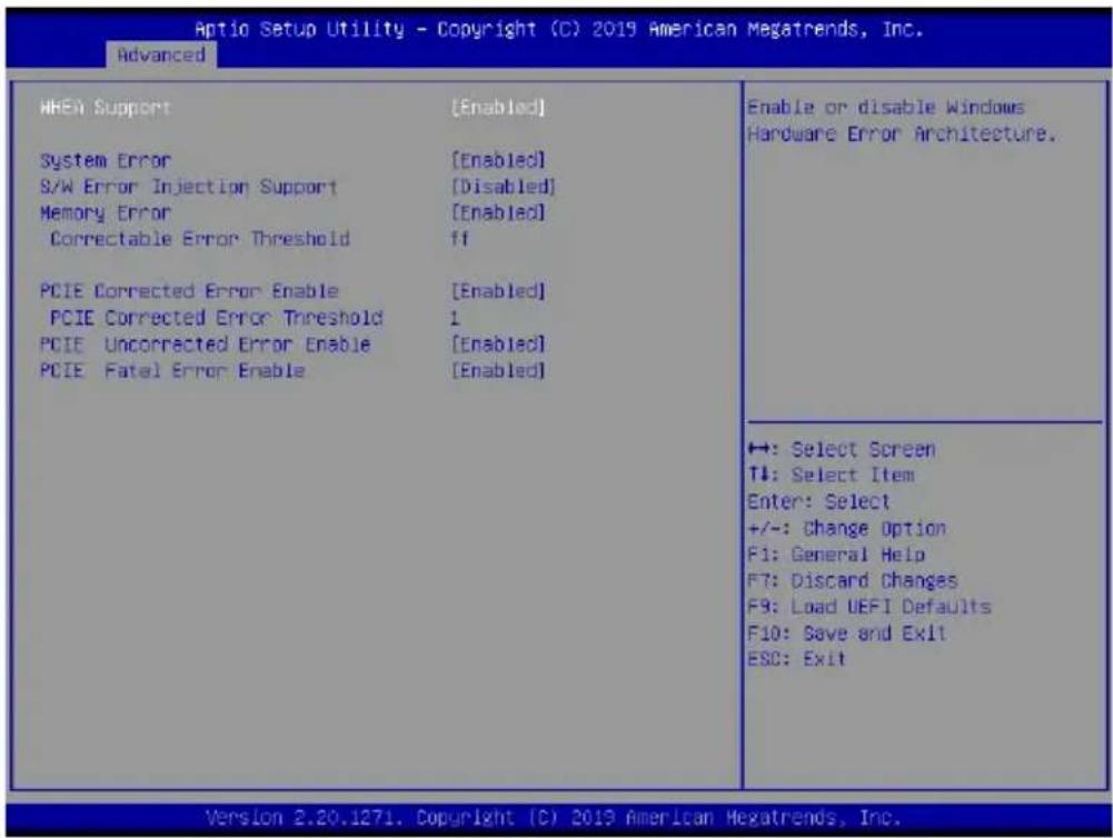
3.3.10 Runtime Error Logging
text_image
Aptio Setup Utility - Copyright (C) 2019 American Megatrends, Inc. Advanced HHEV Support [Enabled] System Error [Enabled] S/W Error Injection Support [Disabled] Memory Error [Enabled] Correctable Error Threshold ff PCIE Corrected Error Enable [Enabled] PCIE Corrected Error Threshold 1 PCIE Uncorrected Error Enable [Enabled] PCIE Fatal Error Enable [Enabled] Enable or disable Windows Hardware Error Architecture. ←: Select Screen T↓: Select Item Enter: Select +/-: Change Option F1: General Help F7: Discard Changes F9: Load UEFI Defaults F10: Save and Exit ESC: Exit Version 2.20.1271. Copyright (C) 2019 American Megatrends, Inc.WHEA Support
Use this item to enable or disable Windows Hardware Error Architecture.
System Error
Use this item to enable or disable System Error feature. When it is set to [Enabled], you can configure Memory Error and PCIE Error log features.
S/W Error Injection Support
When it is set to [Enabled], S/W Error Injection is supported by unlocking MSR Ox790.
Memory Error
Memory enabling and logging setup option.
Correctable Error Threshold
Correctable Error Threshold (0 - 0x7FFF) used for sparing, tagging, and leaky bucket.
PCIE Corrected Error Enable
Use this item to enable or disable PCIe Correctable errors.
PCIE Corrected Error Threshold
PCIE Correctable Error Threshold (0x01-0xFF) used for sparing, tagging, and leaky bucket.
PCIE Uncorrected Error Enable
Use this item to enable or disable PCIe Uncorrectable errors.
PCIE Fatal Error Enable
Use this item to enable or disable PCIe Fatal errors.
3.3.11 Instant Flash
Instant Flash is a UEFI flash utility embedded in Flash ROM. This convenient UEFI update tool allows you to update system UEFI without entering operating systems first like MS-DOS or Windows ^® . Just save the new UEFI file to your USB flash drive, floppy disk or hard drive and launch this tool, then you can update your UEFI only in a few clicks without preparing an additional floppy diskette or other complicated flash utility. Please be noted that the USB flash drive or hard drive must use FAT32/16/12 file system. If you execute Instant Flash utility, the utility will show the UEFI files and their respective information. Select the proper UEFI file to update your UEFI, and reboot your system after the UEFI update process is completed.
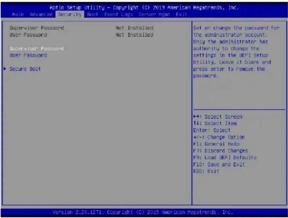
3.4 Security
In this section, you may set or change the supervisor/user password for the system. For the user password, you may also clear it.
text_image
Aptio Setup Utility - Copyright (C) 2019 American Megatrends, Inc. Main Advanced Security Boot Event Logs Server Mgmt Exit Supervisor Password Not Installed User Password Not Installed Supervisor Password User Password ▶ Secure Boot Set or change the password for the administrator account. Only the administrator has authority to change the settings in the UEFI Setup Utility. Leave it blank and press enter to remove the password. ◆: Select Screen ↑: Select Item Enter: Select +/-: Change Option F1: General Help F7: Discard Changes F9: Load UEFI Defaults F10: Save and Exit ESC: Exit ◆: Select Screen ↑: Select Item Enter: Select +/-: Change Option F1: General Help F7: Discard Changes F9: Load UEFI Defaults F10: Save and Exit ESC: Exit Version 2.20.1271. Copyright (C) 2019 American Megatrends, Inc.Supervisor Password
Set or change the password for the administrator account. Only the administrator has authority to change the settings in the UEFI Setup Utility. Leave it blank and press enter to remove the password.
User Password
Set or change the password for the user account. Users are unable to change the settings in the UEFI Setup Utility. Leave it blank and press enter to remove the password.
Secure Boot
Use this to enable or disable Secure Boot Control. The default value is [Disabled]. Enable to support Windows Server 2012 R2 or later versions Secure Boot.
Secure Boot Mode
Secure Boot mode selector: Standard/Custom. In Custom mode, Secure Boot Policy variables can be configured by a physically present user without full authentication.
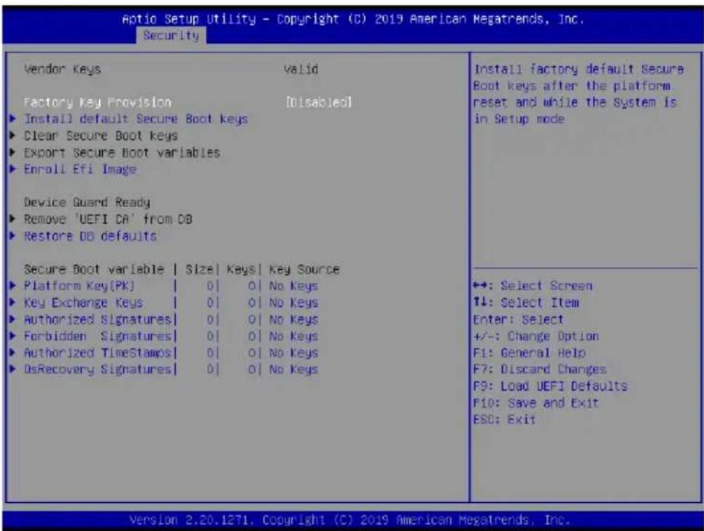
3.4.1 Key Management
In this section, expert users can modify Secure Boot Policy variables without full authentication.
text_image
Aptio Setup Utility - Copyright (C) 2019 American Megatrends, Inc. Security Vendor Keys Valid Factory Key Provision [Disabled] ► Install default Secure Boot keys ► Clear Secure Boot keys ► Export Secure Boot variables ► Enroll Efi Image Device Guard Ready ► Remove 'UEFI DA' from DB ► Restore DB defaults Secure Boot variable | Size | Keys | Key Source ► Platform Key(Pk) | 0 | 0 | No Keys ► Key Exchange Keys | 0 | 0 | No Keys ► Authorized Signatures | 0 | 0 | No Keys ► Forbidden Signatures | 0 | 0 | No Keys ► Authorized TimeStamps | 0 | 0 | No Keys ► OsRecovery Signatures | 0 | 0 | No Keys Install factory default Secure Boot keys after the platform reset and while the System is in Setup mode +: Select Screen ↑↓: Select Item Enter: Select +/-: Change Option F1: General Help F7: Discard Changes F9: Load UEFI Defaults F10: Save and Exit ESC: Exit Version 2.20.1271. Copyright (C) 2019 American Megatrends, Inc.Factory Key Provision
Install factory default Secure Boot keys after the platform reset and while the System is in Setup mode.
Install Default Secure Boot Keys
Please install default secure boot keys if it's the first time you use secure boot.
Clear Secure Boot keys
Force System to Setup Mode - clear all Secure Boot Variables. Change takes effect after reboot.
Export Secure Boot variables
Copy NVRAM content of Secure Boot variables to files in a root folder on a file system device.
Enroll Efi Image
Allow the image to run in Secure Boot mode. Enroll SHA256 Hash certificate of a PE image into Authorized Signature Database (db).
Remove 'UEFI CA' from DB
Device Guard ready system must not list 'Microsoft UEFI CA' Certificate in Authorized Signature database (db).
Restore DB defaults
Restore DB variable to factory defaults.
Platform Key(PK)
Enroll Factory Defaults or load certificates from a file:
- Public Key Certificate in:
a) EFI_SIGNATURE_LIST
b) EFI_CERT_X509 (DER)
c) EFI_CERT_RSA2048 (bin)
d) EFI_CERT_SHA256, 384, 512 - Authenticated UEFI Variable
- EFI PE/COFF Image(SHA256)
Key Source: Factory, External, Mixed
Key Exchange Keys
Enroll Factory Defaults or load certificates from a file:
- Public Key Certificate in:
a) EFI_SIGNATURE_LIST
b) EFI_CERT_X509 (DER encoded)
c) EFI_CERT_RSA2048 (bin)
d) EFI_CERT_SHA256, 384, 512 - Authenticated UEFI Variable
- EFI PE/COFF Image(SHA256)
Key Source: Factory, External, Mixed
Authorized Signatures
Enroll Factory Defaults or load certificates from a file:
-
Public Key Certificate in:
a) EFI_SIGNATURE_LIST
b) EFI_CERT_X509 (DER encoded)
c) EFI_CERT_RSA2048 (bin)
d) EFI_CERT_SHA256, 384, 512 -
Authenticated UEFI Variable
-
EFI PE/COFF Image(SHA256)
Key Source: Factory, External, Mixed
Forbidden Signatures
Enroll Factory Defaults or load certificates from a file:
-
Public Key Certificate in:
a) EFI_SIGNATURE_LIST
b) EFI_CERT_X509 (DER encoded)
c) EFI_CERT_RSA2048 (bin)
d) EFI_CERT_SHA256, 384, 512 -
Authenticated UEFI Variable
-
EFI PE/COFF Image(SHA256)
Key Source: Factory, External, Mixed
Authorized TimeStamps
Enroll Factory Defaults or load certificates from a file:
- Public Key Certificate in:
a) EFI_SIGNATURE_LIST
b) EFI_CERT_X509 (DER encoded)
c) EFI_CERT_RSA2048 (bin)
d) EFI_CERT_SHA256, 384, 512 - Authenticated UEFI Variable
- EFI PE/COFF Image(SHA256)
Key Source: Factory, External, Mixedt
OsRecovery Signatures
Enroll Factory Defaults or load certificates from a file:
- Public Key Certificate in:
a) EFI_SIGNATURE_LIST
b) EFI_CERT_X509 (DER encoded)
c) EFI_CERT_RSA2048 (bin)
d) EFI_CERT_SHA256, 384, 512 - Authenticated UEFI Variable
- EFI PE/COFF Image(SHA256)
Key Source: Default, External, Mixed, Test
3.5 Boot Screen
In this section, it will display the available devices on your system for you to configure the boot settings and the boot priority.
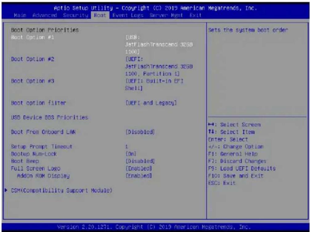
text_image
Aptio Setup Utility - Copyright (C) 2019 American Megatrends, Inc. Main Advanced Security Boot Event Logs Server Ngmt Exit Boot Option Priorities Boot Option #1 [USB: JetFlashTranscend 32GB 1100] Boot Option #2 [UEFI: JetFlashTranscend 32GB 1100, Partition 1] Boot Option #3 [UEFI: Built-in EFI Shell] Boot option filter [UEFI and Legacy] USB Device BBS Priorities Boot From Onboard LAN [Disabled] Setup Prompt Timeout 1 Bootup Num-Lock [On] Boot Beep [Disabled] Full Screen Logo [Enabled] AddOn ROM Display [Enabled] ► CSM(Compatibility Support Module) Sets the system boot order ←: Select Screen ↑4: Select Item Enter: Select +/-: Change Option F1: General Help F7: Discard Changes F9: Load UEFI Defaults F10: Save and Exit ESC: Exit Version 2.20.1271. Copyright (C) 2019 American Megatrends, Inc.Boot Option #1
Use this item to set the system boot order.
Boot Option #2
Use this item to set the system boot order.
Boot Option #3
Use this item to set the system boot order.
Boot Option Filter
This option controls Legacy/UEFI ROMs priority.
USB Device BBS Priorities
This page will show only when system install USB Storage.
Boot From Onboard LAN
Use this item to enable or disable the Boot From Onboard LAN feature.
Setup Prompt Timeout
Configure the number of seconds to wait for the UEFI setup utility.
Bootup Num-Lock
If this item is set to [On], it will automatically activate the Numeric Lock function after boot-up.
Boot Beep
Select whether the Boot Beep should be turned on or off when the system boots up. Please note that a buzzer is needed.
Full Screen Logo
Enable to display the boot logo or disable to show normal POST messages
AddOn ROM Display
Use this option to adjust AddOn ROM Display. If you enable the option “Full Screen Logo” but you want to see the AddOn ROM information when the system boots, please select [Enabled]. Configuration options: [Enabled] and [Disabled]. The default value is [Enabled].
3.5.1 CSM(Compatibility Support Module)
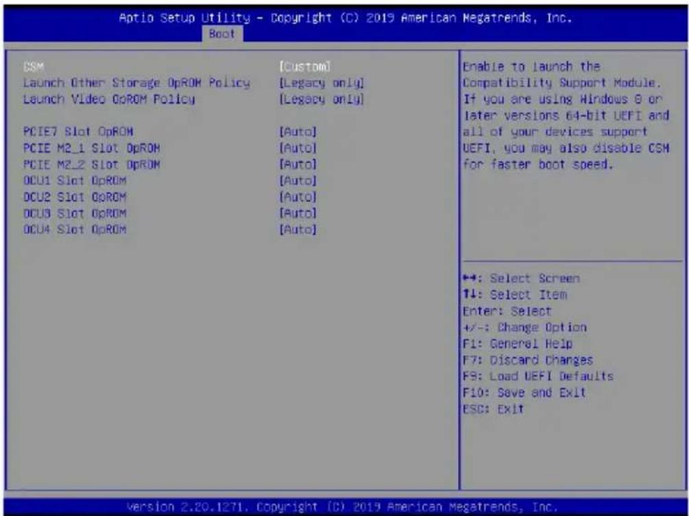
text_image
Aptio Setup Utility - Copyright (C) 2019 American Megatrends, Inc. Boot CSM Launch Other Storage OpROM Policy Launch Video OpROM Policy PCIE7 Slot OpROM PCIE M2_1 Slot OpROM PCIE M2_2 Slot OpROM OCU1 Slot OpROM OCU2 Slot OpROM OCU3 Slot OpROM OCU4 Slot OpROM [Custom] [Legacy only] [Legacy only] [Auto] [Auto] [Auto] [Auto] [Auto] Enable to launch the Compatibility Support Module. If you are using Windows 8 or later versions 64-bit UEFI and all of your devices support UEFI, you may also disable CSM for faster boot speed. +4: Select Screen ↑↓: Select Item Enter: Select +/-: Change Option F1: General Help F7: Discard Changes F9: Load UEFI Defaults F10: Save and Exit ESC: Exit Version 2.20.1271, Copyright (C) 2019 American Megatrends, Inc.CSM
Enable to launch the Compatibility Support Module. Please do not disable unless you're running a WHCK test. If you are using Windows Server 2012 R2 or later versions 64-bit UEFI and all of your devices support UEFI, you may also disable CSM for faster boot speed.
Launch Other Storage OpROM Policy
Select UEFI only to run those that support UEFI option ROM only. Select Legacy only to run those that support legacy option ROM only. Select Do not launch to not execute both legacy and UEFI option ROM.
Launch Video OpROM Policy
Select UEFI only to run those that support UEFI option ROM only. Select Legacy only to run those that support legacy option ROM only. Select Do not launch to not execute both legacy and UEFI option ROM.
PCIE7 Slot OpROM
Use this item to select slot storage and Network Option ROM policy. In Auto option, the default is Disabled with NVMe device, but it is Legacy with other devices. (This item can't select Video Option ROM policy.)
PCIE M2\_1 Slot OpROM
Use this item to select slot storage and Network Option ROM policy. In Auto option, the default is Disabled with NVMe device, but it is Legacy with other devices. (This item can't select Video Option ROM policy.)
PCIE M2\_2 Slot OpROM
Use this item to select slot storage and Network Option ROM policy. In Auto option, the default is Disabled with NVMe device, but it is Legacy with other devices. (This item can't select Video Option ROM policy.)
OCU1 Slot OpROM
Use this item to select slot storage and Network Option ROM policy. In Auto option, the default is Disabled with NVMe device, but it is Legacy with other devices. (This item can't select Video Option ROM policy.)
OCU2 Slot OpROM
Use this item to select slot storage and Network Option ROM policy. In Auto option, the default is Disabled with NVMe device, but it is Legacy with other devices. (This item can't select Video Option ROM policy.)
OCU3 Slot OpROM
Use this item to select slot storage and Network Option ROM policy. In Auto option, the default is Disabled with NVMe device, but it is Legacy with other devices. (This item can't select Video Option ROM policy.)
OCU4 Slot OpROM
Use this item to select slot storage and Network Option ROM policy. In Auto option, the default is Disabled with NVMe device, but it is Legacy with other devices. (This item can't select Video Option ROM policy.)
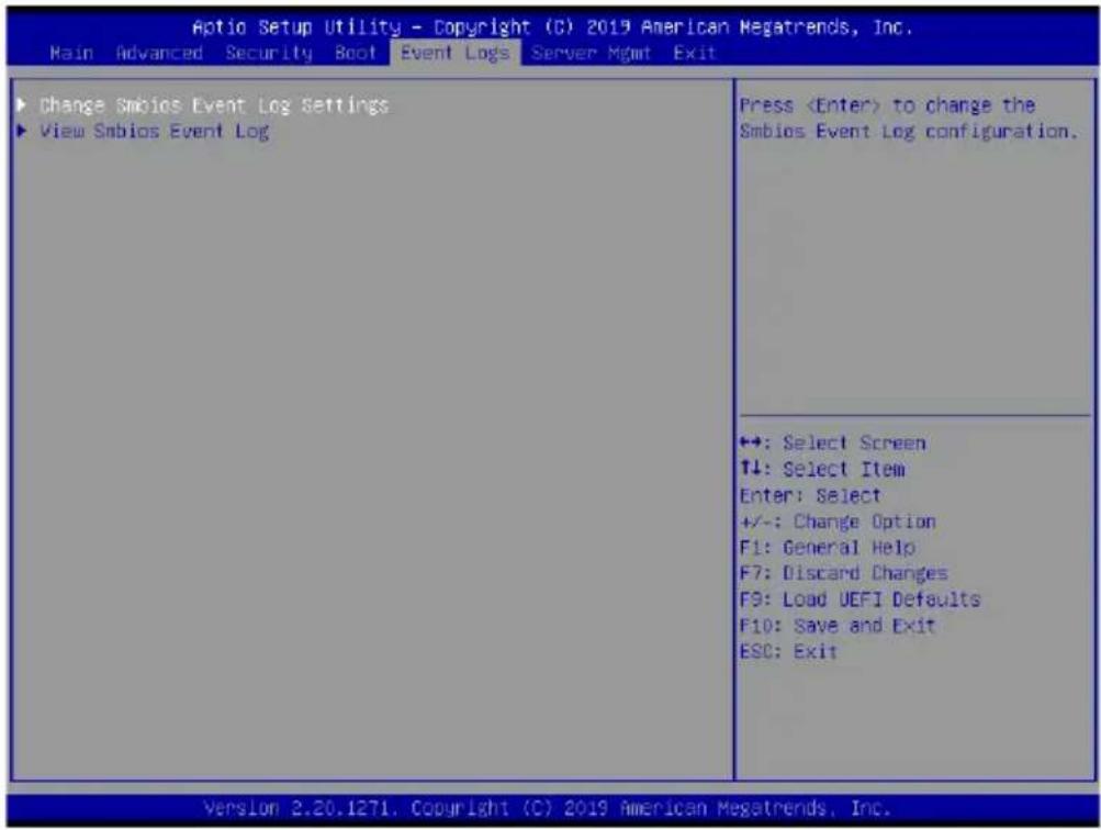
3.6 Event Logs
text_image
Aptio Setup Utility - Copyright (C) 2019 American Megatrends, Inc. Main Advanced Security Boot Event Logs Server Mgmt Exit Change Smbios Event Log Settings View Smbios Event Log PressChange Smbios Event Log Settings
This allows you to configure the Smbios Event Log Settings.
When entering the item, you will see the followings:
Smbios Event Log
Use this item to enable or disable all features of the SMBIOS Event Logging during system boot.
Erase Event Log
The options include [No], [Yes, Next reset] and [Yes, Every reset]. If Yes is selected, all logged events will be erased.
When Log is Full
Use this item to choose options for reactions to a full Smbios Event Log. The options include [Do Nothing] and [Erase Immediately].
Log System Boot Event
Choose option to enable/disable logging of System boot event.
View Smbios Event Log
Press

All values changed here do not take effect until computer is restarted.
3.7 Server Mgmt
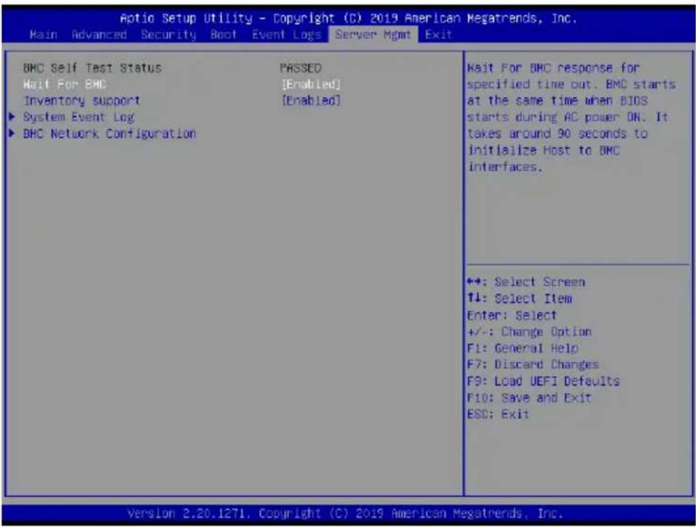
text_image
Aptio Setup Utility - Copyright (C) 2019 American Megatrends, Inc. Main Advanced Security Boot Event Logs Server Mgmt Exit BMC Self Test Status PASSED Halt For BMC [Enabled] Inventory support [Enabled] ► System Event Log ► BMC Network Configuration Wait For BMC response for specified time out. BMC starts at the same time when BIOS starts during AC power ON. It takes around 90 seconds to initialize Host to BMC interfaces. ◆: Select Screen ↑↓: Select Item Enter: Select +/-: Change Option F1: General Help F7: Discard Changes F9: Load UEFI Defaults F10: Save and Exit ESD: Exit ◆+: Select Screen ↑↓: Select Item Enter: Select +/-: Change Option F1: General Help F7: Discard Changes F9: Load UEFI Defaults F10: Save and Exit ESD: Exit Version 2.20.1271, Copyright (C) 2019 American Megatrends, Inc.Wait For BMC
Wait For BMC response for specified time out. BMC starts at the same time when BIOS starts during AC power ON. It takes around 90 seconds to initialize Host to BMC interfaces.
Inventory Support
This will execute inventory function for system. Enabling this item will take some time at system boot.
3.7.1 System Event Log
text_image
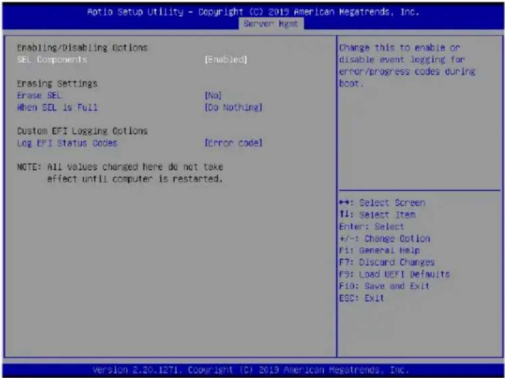
Aptio Setup Utility - Copyright (C) 2019 American Megatrends, Inc. Server: Rgmt Enabling/Disabling Options SEL Components [Enabled] Erasing Settings Erase SEL [No] When SEL is Full [Do Nothing] Custom EFI Logging Options Log EFI Status Codes [Error code] NOTE: All values changed here do not take effect until computer is restarted. Change this to enable or disable event logging for error/progress codes during boot. +: Select Screen +: Select Item Enter: Select +/-: Change Option F1: General Help F7: Discard Changes F9: Load UEFI Defaults F10: Save and Exit ESC: Exit Version 2.20.1271, Copyright (C) 2019 American Megatrends, Inc.SEL Components
Change this to enable ro disable event logging for error/progress codes during boot.
Erase SEL
Use this to choose options for earsing SEL.
When SEL is Full
Use this to choose options for reactions to a full SEL.
Log EFI Status Codes
Use this item to disable the logging of EFI Status Codes or log only error code or only progress code or both.
3.7.2 BMC Network Configuration
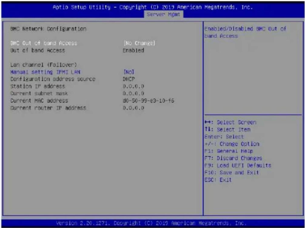
text_image
Aptio Setup Utility - Copyright (C) 2019 American Megatrends, Inc. Server Mgmt BMC Network Configuration BMC Out of band Access [No Change] Out of band Access Enabled Lan channel (Failover) Manual setting IPMI LAN [No] Configuration address source DHCP Station IP address D.0.0.0 Current subnet mask D.0.0.0 Current MAC address d0-50-99-e3-10-f6 Current router IP address D.0.0.0 Enabled/Disabled BMC Out of band Access ←: Select Screen ↑↓: Select Item Enter: Select +/-: Change Option F1: General Help F7: Discard Changes F9: Load UEFI Defaults F10: Save and Exit ESC: Exit Version 2.20.1271. Copyright (C) 2019 American Megatrends, Inc.BMC Out of Band Access
Enabled/Disabled BMC Out of band Access.
Lan Channel (Failover)
Manual Setting IPMI LAN
If [No] is selected, the IP address is assigned by DHCP. If you prefer using a static IP address, toggle to [Yes], and the changes take effect after the system reboots. The default value is [No].
Configuration Address Source
Select to configure BMC network parameters statically or dynamically(by BIOS or BMC). Configuration options: [Static] and [DHCP].
Static: Manually enter the IP Address, Subnet Mask and Gateway Address in the BIOS for BMC LAN channel configuration.
DHCP: IP address, Subnet Mask and Gateway Address are automatically assigned by the network's DHCP server.

When [DHCP] or [Static] is selected, do NOT modify the BMC network settings on the IPMI web page.

The default login information for the IPMI web interface is:
Username: admin
Password: admin
For more instructions on how to set up remote control environment and use the IPMI management platform, please refer to the IPMI Configuration User Guide or go to the Support website at: http://www.asrockrack.com/support/ipmi.asp
3.8 Exit Screen
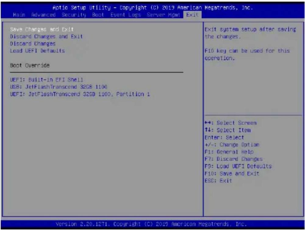
text_image
Aptio Setup Utility - Copyright (C) 2019 American Megatrends, Inc. Main Advanced Security Boot Event Logs Server Mgmt Exit Save Changes and Exit Discard Changes and Exit Discard Changes Load UEFI Defaults Boot Override UEFI: Built-In EFI Shell USB: JetFlashTranscend 32GB 1100 UEFI: JetFlashTranscend 32GB 1100, Partition 1 Exit system setup after saving the changes. F10 key can be used for this operation. ++: Select Screen ↑↓: Select Item Enter: Select +/-: Change Option F1: General Help F7: Discard Changes F9: Load UEFI Defaults F10: Save and Exit ESC: Exit Version 2.20.1271, Copyright (C) 2019 American Megatrends, Inc.Save Changes and Exit
When you select this option, the following message "Save configuration changes and exit setup?" will pop-out. Press
Discard Changes and Exit
When you select this option, the following message “Discard changes and exit setup?” will pop-out. Press
Discard Changes
When you select this option, the following message "Discard changes?" will pop-out. Press
Load UEFI Defaults
Load UEFI default values for all the setup questions. F9 key can be used for this operation.
Boot Override
These items displays the available devices. Select an item to start booting from the selected device.
Chapter 4 Software Support
4.1 Install Operating System
This motherboard supports various Microsoft® Windows® Server 2012 R2 / 2016 / Linux compliant. Because motherboard settings and hardware options vary, use the setup procedures in this chapter for general reference only. Refer to your OS documentation for more information.
4.2 Support CD Information
The Support CD that came with the motherboard contains necessary drivers and useful utilities that enhance the motherboard's features.
4.2.1 Running The Support CD
To begin using the support CD, insert the CD into your CD-ROM drive. The CD automatically displays the Main Menu if “AUTORUN” is enabled in your computer. If the Main Menu does not appear automatically, locate and double click on the file “ASRSetup.exe” from the root folder in the Support CD to display the menu.
4.2.2 Drivers Menu
The Drivers Menu shows the available device's drivers if the system detects installed devices. Please install the necessary drivers to activate the devices.
4.2.3 Utilities Menu
The Utilities Menu shows the application softwares that the motherboard supports. Click on a specific item then follow the installation wizard to install it.
4.2.4 Contact Information
If you need to contact ASRock Rack or want to know more about ASRock Rack, welcome to visit ASRock Rack's website at http://www.ASRockRack.com; or you may contact your dealer for further information.
Chapter 5 Troubleshooting
5.1 Troubleshooting Procedures
Follow the procedures below to troubleshoot your system.

Always unplug the power cord before adding, removing or changing any hardware components. Failure to do so may cause physical injuries to you and damages to motherboard components.
- Disconnect the power cable and check whether the PWR LED is off.
- Unplug all cables, connectors and remove all add-on cards from the motherboard. Make sure that the jumpers are set to default settings.
- Confirm that there are no short circuits between the motherboard and the chassis.
- Install a CPU and fan on the motherboard, then connect the chassis speaker and power LED.
If there is no power...
- Confirm that there are no short circuits between the motherboard and the chassis.
- Make sure that the jumpers are set to default settings.
- Check the settings of the 115V/230V switch on the power supply.
- Verify if the battery on the motherboard provides \~3VDC. Install a new battery if it does not.
If there is no video...
- Try replugging the monitor cables and power cord.
- Check for memory errors.
If there are memory errors...
- Verify that the DIMM modules are properly seated in the slots.
- Use recommended DDR4 ECC RDIMMs/LR DIMMs.
- If you have installed more than one DIMM modules, they should be identical with the same brand, speed, size and chip-type.
- Try inserting different DIMM modules into different slots to identify faulty ones.
- Check the settings of the 115V/230V switch on the power supply.
Unable to save system setup configurations...
- Verify if the battery on the motherboard provides \~3VDC. Install a new battery if it does not.
- Confirm whether your power supply provides adequate and stable power.
Other problems...
- Try searching keywords related to your problem on ASRock Rack's FAQ page: http://www.asrockrack.com/support
5.2 Technical Support Procedures
If you have tried the troubleshooting procedures mentioned above and the problems are still unsolved, please contact ASRock Rack's technical support with the following information:
- Your contact information
- Model name, BIOS version and problem type.
- System configuration.
- Problem description.
You may contact ASRock Rack's technical support at:
http://www.asrockrack.com/support/tsd.asp
5.3 Returning Merchandise for Service
For warranty service, the receipt or a copy of your invoice marked with the date of purchase is required. By calling your vendor or going to our RMA website (http://event.asrockrack.com/tsd.asp) you may obtain a Returned Merchandise Authorization (RMA) number.
The RMA number should be displayed on the outside of the shipping carton which is mailed prepaid or hand-carried when you return the motherboard to the manufacturer. Shipping and handling charges will be applied for all orders that must be mailed when service is complete.
This warranty does not cover damages incurred in shipping or from failure due to alteration, misuse, abuse or improper maintenance of products.
Contact your distributor first for any product related problems during the warranty period.