
DMA8825 - Receiver PHONIC - Free user manual and instructions
Find the device manual for free DMA8825 PHONIC in PDF.


| Product Type | Digital Matrix Amplifier |
| Model | DMA8825 |
| Brand | Phonic (by Asystems) |
| Channels | 8 inputs (Euroblock + RCA), 8 amplified outputs (Euroblock) |
| Power Output (Stereo, 8Ω) | 150W per channel, all channels driven |
| Power Output (Stereo, 4Ω) | 250W per channel, all channels driven |
| Power Output (Bridge, 8Ω) | 500W per channel (4 bridged pairs) |
| Distributed Output | 250W per channel at 70.7V/100V |
| Dimensions (W x H x D) | 483 x 89 x 394 mm (19" x 3.5" x 15.5") |
| Weight | 9.53 kg (21 lbs) |
| Power Supply | 120/230 VAC, 50/60 Hz, 15A Edison |
| Input Connections | 3-pin Euroblock (balanced/unbalanced) + stereo RCA |
| Output Connections | 3-pin Euroblock (amplified and line-level) |
| Digital I/O | AES/EBU input/output, Word Clock (BNC) |
| Network | Ethernet RJ-45 (100Base-T), Dante optional (DT44/DT88 card) |
| DSP | 40-bit floating point, sample rate 44.1/48 kHz |
| Built-in Processing | 4-band parametric EQ, 31-band graphic EQ, compressor, limiter, ALC, ducker, feedback silencer, crossover, signal generator |
| Control | Onboard via VGA + USB mouse, Windows software, optional RM-2VR/RM-4/RM-6E remotes |
| Rack Mount | 2U, 19-inch standard rack |
| Cooling | Temperature-dependent speed-controlled axial fan |
| Protection | Inrush current limit, temperature monitoring, over-current protection, mains fuses |
| Safety | Class I, grounded plug; do not expose to moisture; disconnect mains before cleaning |
| Cleaning | Use only dry cloth; no liquid or aerosol cleaners |
| Spare Parts / Accessories | Expansion cards (DT44/DT88), remote controls (RM series), USB mouse, VGA monitor (not included) |
| Warranty | Refer to manufacturer (Asystems) |
Frequently Asked Questions - DMA8825 PHONIC
User questions about DMA8825 PHONIC
0 question about this device. Answer the ones you know or ask your own.
Ask a new question about this device
Download the instructions for your Receiver in PDF format for free! Find your manual DMA8825 - PHONIC and take your electronic device back in hand. On this page are published all the documents necessary for the use of your device. DMA8825 by PHONIC.
USER MANUAL DMA8825 PHONIC
natural_image
Abstract black geometric logo resembling the letter 'A' on white background (no text or symbols)SYSTEMS
INSTALLATION AND SETUP 5
RACK MOUNTING....5
CONNECTION 5
DIGITAL I/O EXPANSION CARD 6
IMPORTANT SAFETY INSTRUCTIONS
The apparatus shall not be exposed to dripping or splashing and that no objects filled with liquids, such as vases, shall be placed on the apparatus. The MAINS plug is used as the disconnect device, the disconnect device shall remain readily operable.
Warning: the user shall not place this apparatus in the confined area during the operation so that the mains switch can be easily accessible.
-
Read these instructions before operating this apparatus.
-
Keep these instructions for future reference.
-
Heed all warnings to ensure safe operation.
-
Follow all instructions provided in this document.
-
Do not use this apparatus near water or in locations where condensation may occur.
-
Clean only with dry cloth. Do not use aerosol or liquid cleaners. Unplug this apparatus before cleaning.
-
Do not block any of the ventilation openings. Install in accordance with the manufacturer's instructions.
-
Do not install near any heat sources such as radiators, heat registers, stoves, or other apparatus (including amplifiers) that produce heat.
-
Do not defeat the safety purpose of the polarized or grounding-type plug. A polarized plug has two blades with one wider than the other. A grounding type plug has two blades and a third grounding prong. The wide blade or the third prong is provided for your safety. If the provided plug does not fill into your outlet, consult an electrician for replacement of the obsolete outlet.
-
Protect the power cord from being walked on or pinched particularly at plug, convenience receptacles, and the point where they exit from the apparatus.
-
Only use attachments/accessories specified by the manufacturer.
-
Use only with a cart, stand, tripod, bracket, or table specified by the manufacturer, or sold with the apparatus. When a cart is used, use caution
when moving the cart/apparatus combination to avoid injury from tip-over.
- Unplug this apparatus during lighting storms or when unused for long periods of time.

- Refer all servicing to seavified personnel. Servicing is required when the apparatus has been damaged in any way, such as power-supply cord or plug is damaged, liquid has been spilled or objects have fallen into the apparatus, the apparatus has been exposed to rain or moisture, does not operate normally, or has been dropped.

CAUTION: TO REDUCE THE RISK OF ELECTRIC SHOCK, DO NOT REMOVE COVER (OR BACK) NO USER SERVICEABLE PARTS INSIDE REFER SERVICING TO QUALIFIED PERSONNEL

The lightning flash with arrowhead symbol, within an equilateral triangle, is intended to alert the user to the presence of uninsulated "dangerous voltage" within the product's enclosure that may be of sufficient magnitude to constitute a risk of electric shock to persons.

The exclamation point within an equilateral triangle is intended to alert the user to the presence of important operating and maintenance (servicing) instructions in the literature accompanying the appliance.
WARNING: To reduce the risk of fire or electric shock, do not expose this apparatus to rain or moisture.
CAUTION: Use of controls or adjustments or performance of procedures other than those perceived result in hazardous radiation exposure.
1. INTRODUCTION
Congratulations on your purchase of a DMA series digital matrix amplifier. The DMA's flexible deisgn will provide you with up to eight channels of audio matrixing and processing. A single DMA amplifier offers eight-in, eight-out support (or eight-in, four-out), and the entire system can be controlled through standard potentiometers, remote controls or flexible remote software. Internal processing is accomplished through a high quality 40-bit floating point processor, with internal signal processors and matrix routing all handled with ease.
DMA digital matrix amplifiers offer easy, effective means for injecting signal processors directly into your input and output path, with clear, easy-to-use software both onboard and on your Windows computer. The software offers full performance monitoring for each processor, giving real-time information on the load placed upon DSPs.
2. FEATURES
- 8 input channels available via 3-pin Euroblock connections and stereo RCA inputs
• Full control possible through onboard software accessed with VGA display and USB mouse connected - Built-in multi-channel amplifier for low-impedance or line distribution application*
- For power output levels for individual models, please consult the Specifications on page 17
- 40-bit floating point processor with internal sampling selectable between 44.1 and 48 kHz
- Optional 4x4 or 8x8 networking capabilities through audio streaming LAN card
• Digital AES/EBU input and output connectors - Auto shutdown mode for reduced power consumption
- Ethernet connectivity for network and internet control application
• Automatic DHCP network IP configuration - Easy and intuitive control software from Asystems
• Event scheduling and user-accounts - 4-band parametric EQs and 31-band graphic equalizers
- Adjustable compressors and limiters built-in
• Feedback silencing technology seeks and destroys feedback - User-defined crossovers available on output channels
• Autoleveler (Loudness Control)
• Level ducking with trigger control
*Operating mode is dependent on purchased model.
3. CONTROLS AND I/O
FRONT PANEL

1. Mounting Holes
These holes are for mounting the DMA device in a standard 19" rack.
2. Output Level Control Knobs
Every output channel is equipped with a rotary knob for adjusting the final output level. These controls can be deactivated within the DMA software.
3. OUT LED
Every output channel is equipped with a 4-segment IN LED level meter, including a CLIP/PROTECT indicator.
4. BRIDGE LED
This LED lights when the two corresponding channels are bridged with one another.
NOTE: Every input channel is equipped with one output level control knob, one IN LED and 1 level meter. Each channel pair features a BRIDGE LED.
5. Cooling Inlet Vents
Cool air is drawn in here. Please do not cover these vents for any reason as you risk overheating the DMA.
6. Reset Button
A pinhole button is included for resetting the DMA series matrix amplifier to the factory default settings.
7. Indicators
POWER: Lights when the device is on.
DISABLE: Lights when the power switch is disabled.
STANDBY/UNLOCK: Lights when DMA device is in the Standby mode.
PROTECT: Lights when the protect circuitry is active.
8. Power Switch
Flick this switch to turn the unit on and enter it into STANDBY mode. Please note that this switch can be disabled through the onboard software. If the power switch becomes unresponsive, check your power settings.
WARNING: The DMA requires up to 2 minutes to be fully discharged after the power is turned off. During this time the system cannot be powered on properly.
REAR PANEL
The Asystems DMA8825, DMA8813, DMA8425 and DMA8413 share the same basic I/O design and layout. The major difference is that the DMA8825 and DMA8813 have 8 speaker output connectors and 8 line-out connectors, while the DMA8425 and DMA8413 have 4 speaker output connectors and 4 line-out connectors (as shown below).

1. AC Power Connector
This power inlet is for connecting a standard IEC power cable. Under no circumstances should the user remove the grounding pin on the power cable.
2. AES/EBU Connector
For connecting AES/EBU-enabled devices.
3. RS-232 Connector
For remote control through non-Ethernet based hardware that utilizes a RS-232 control data protocol. This feature is only found on the DMA8825. A detailed protocol document can be found on the Asystems website.
4. VGA Connector
Connect this port to an appropriate video screen to view the DMA's internal software. This can be controlled by any connected wired or wireless mouse.
5. SD Card Slot
Insert an SD card here to play digital audio files.
6. WCLK Connector
This port is for connection of a master clock, enabling multiple digital audio devices to be perfectly synchronized.
7. USB Ports
These USB ports are for connection of a standard wired or wireless USB mouse for stand-alone control of the internal software. The second USB port can be used when performing firmware updates.
8. SPEAKER OUTPUTS (Amplified Output)
For connecting passive loudspeakers.
9. PERIPHERAL Connector
For connecting the Asystems RM-6E programmable remote control (sold separately).
10. PRESET RECALL Connector
For connecting Asystems' RM-4 series remote preset recall control (sold separately).
11. REMOTE LEVEL CONTROL Connector
For connecting Asystems' RM-2VR series remote level control (sold separately).
12. INPUT Connectors
Two types of input connectors are offered - Euroblock and unbalanced RCA.
13. OUTPUT Connectors
DMA matrix amplifiers adopt 3-pin Euroblock output connectors for line-level output. These can be used as balanced or unbalanced connections (see section "Audio Output" on page 6 for more).
14. DIGITAL I/O Expansion Card Slot
This slot is for installing Asystems' DT44 or DT88 Dante Networking card to enable the DMA as a networking portal to other Dante-enabled devices.
15. ETHERNET Connector
RJ-45 connector for connecting the DMA8825, DMA8813, DMA8425 or DMA8413 to a PC or local area network.
4. INSTALLATION AND SETUP
4.1 RACK MOUNTING
DMA8825, DMA8813, DMA8425 and DMA8413 are compatible with standard 19" audio equipment racks. Slide the DMA in to the rack and secure it with four Phillips screws and appropriate square nuts. The DMA matrix amplifiers all take up 2 standard units of rack space.

natural_image
Front view of a server rack with indicator lights and a warning symbol (no readable text or labels)4.2 CONNECTIONS
Connect all necessary input and output devices.

AUDIO INPUT
Input can be achieved through correctly wiring the Euroblock connectors and RCA connectors
Euroblock Connectors RCA Connectors


Balanced
PIN 1: Shield/Ground
PIN 2: Cold (-)
PIN 3: Hot (+)
Unbalanced
PIN 1: Shield/Ground
PIN 2: Link to PIN 1
PIN 3: Hot (+)
AUDIO OUTPUT
AMPLIFIED OUTPUTS
These euroblock outputs are used to connect speakers, either in low-impedance or distributed lines depending on your model. Amplified outputs are wired like so:
PIN 1: Cold (-)
PIN 2: Hot (+)
Each pair of amplified output channels can be bridged into one channel. This combines the output power of both channels creating a single channel with twice as much power.
To bridge channels, just wire the "+" pin of an odd-numbered channel to the "+" pin of the next even channel. When bridged, the "+" pin of the even channel becomes the "-" pin of the bridged new output.
When activating bridge mode, be sure to go into the Control Panel menu of the DMA software and click the corresponding "Bridged" button.
AUX OUTPUTS
Offering line-level signals, AUX OUTPUT connectors can be wired as either as balanced or unbalanced connections.

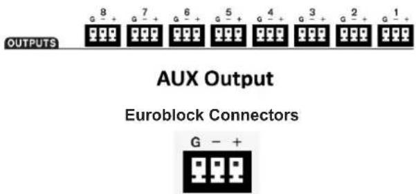
Balanced
PIN 1: Shield/Ground
PIN 2: Cold (-)
PIN 3: Hot (+)
Unbalanced
PIN 1: Shield/Ground
PIN 2: Link to PIN 1
PIN 3: Hot (+)
DIGITAL I/O EXPANSION CARD
- Loosen the two screws and remove the cover plate.

- Connect the DT44 or DT88 Dante Networking card.

- Tighten the two screws back to secure the cover plate.

ONBOARD CONTROL
DMA8825, DMA8813, DMA8425 and DMA8413 include built-in control software. You can get full control over the DMA matrix amplifier via the control software by plugging in a standard VGA display and a USB mouse to the ports shown below.

REMOTE CONTROL
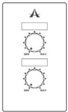
1. RM-2VR REMOTE LEVEL CONTROL
Please connect Asystems' RM-2VR Remote Control to the REMOTE LEVEL CONTROL connectors of the DMA matrix amplifier. The channels controlled by the VR is determined by the wiring of the control. Please note, the ground for channel 2 is internally wired to channel 1. Only one grounding pin needs to be connected to the DMA.
In the example found to the right, channels one and two can be remotely controlled using the RM-2VR.

2. RM-4 REMOTE PRESET RECALL CONTROL
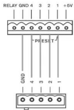
With Asystems' RM-4 Remote Preset Recall connected to the PRESET connector and some configurations within the control software, 4 presets can be accessed via pressing a button. See page 15 for more information on setting presets.


3. RM-6E PROGRAMMABLE REMOTE CONTROL
The Asystems RM-6E Programmable Remote Control can be connected to the PERIPHERAL connector on the rear of the DMA. The DIP switch on the RM-6E determines which communication port the remote will use (see configurations below). Up to 6 functions can be programmed to be controlled remotely using the RM-6E. See page 16 for more information.



4. WINDOWS-BASED PC
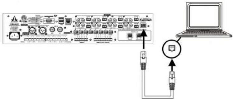
DMA8825, DMA8813, DMA8425 and DMA8413 can be controlled via a connected Windows-based PC.
- Connect the Ethernet port of the DMA to the Ethernet port of your computer with a CAT5 RJ-45 Ethernet cable.
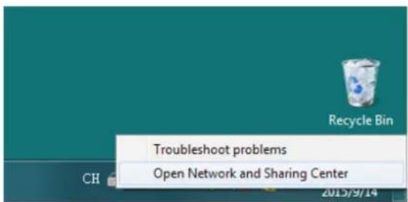
- On your PC, right click your network icon and select "Open Network and Sharing Center".
- Double click your main connection located next to the "Connections".

- Click "Properties" Properties button.
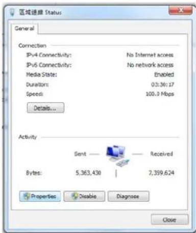
- Select "Internet Protocol Version 4 (TCP/IPv4)" and then click the "Properties" button.

- Change the field "IP address" to "192.168.10.3", and then click "OK".

- Within the Login box of the DMA software, enter the following:
IP Address: 192.168.10.200
User Name: USER 1
Password: ASYSTEMS

Hint: In the event you are unable to log in using any of the main user accounts, connect a monitor and mouse to the DMA digital matrix amplifier. This will allow you to view network settings while in stand-alone mode and reset all accounts.
-
Launch the control software by double clicking the executable file. The latest version of the DMA software can always be found on the Asystems website.
-
Click

5. CONTROL SOFTWARE
DSP
The DSP page will give you an overall profile of input and output mixes as well as assigned signal processors.
Name Cell: The white boxes at the left and right of each row will display the name of each input and output channel. Users can edit the name for each channel by double-clicking on the white box.
ON/OFF: This button will allow the user to switch the corresponding input channel on and off.
Signal Processor Cells: Every input/output channel has a row of four arrow shape cells. Assign any of the internal DSP functions by right-clicking any of these cells.
Channel In: Clicking the blue bar to the left of the screen will jump directly to the "Channel In Matrix" tab.

flowchart
graph TD
    subgraph Channel_In
        CH1["CH1"] --> MixIn["Mix In"]
        CH2["CH2"] --> MixIn
        CH3["CH3"] --> MixIn
        CH4["CH4"] --> MixIn
        CH5["CH5"] --> MixIn
        CH6["CH6"] --> MixIn
        CH7["CH7"] --> MixIn
        CH8["CH8"] --> MixIn
    end

    subgraph Mix_Out
        CH1 --> ChannelOut["Channel Out"]
        CH2 --> ChannelOut
        CH3 --> ChannelOut
        CH4 --> ChannelOut
        CH5 --> ChannelOut
        CH6 --> ChannelOut
        CH7 --> ChannelOut
        CH8 --> ChannelOut

    end

    style Channel_In fill:#f9f,stroke:#333
    style Mix_In fill:#ccf,stroke:#333
    style Channel_Out fill:#cfc,stroke:#333
    style DSP_1Usage fill:#fff,stroke:#000
    style DSP_2Usage fill:#fff,stroke:#000
Mix In/Mix Out: Clicking this red bar allows the user to jump directly to the "Mix Matrix" tab.
Channel Out: Clicking this green bar allows the user direct access to the "Control Panel" tab.
Clear: Clicking this button resets all DSP configurations.
Channel In Matrix
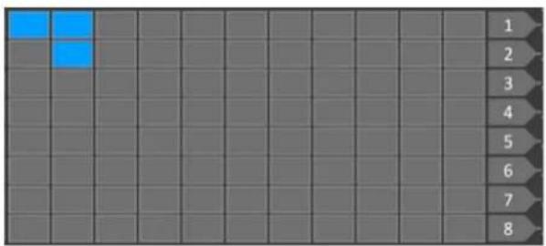
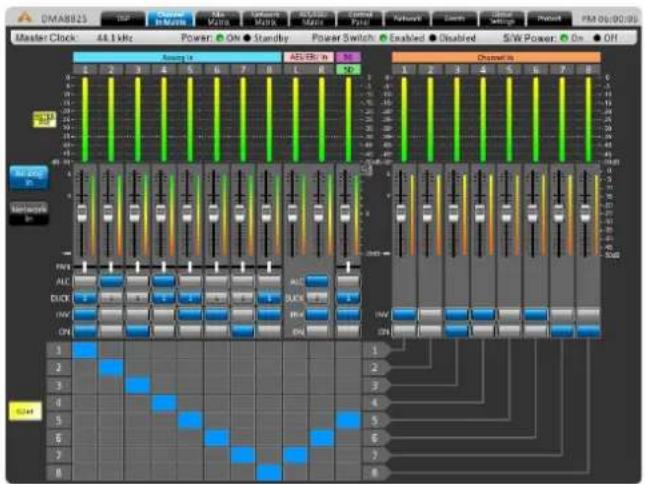
In this page, you can assign any input source to any input channel by clicking the corresponding cell in the cell matrix.
Example:
The image below shows how to assign input source 1 and 2 to Channel In 1, and Input source 2 to Channel In 2.
natural_image
Grid background with eight numbered rows and two highlighted blue squares (no text or symbols)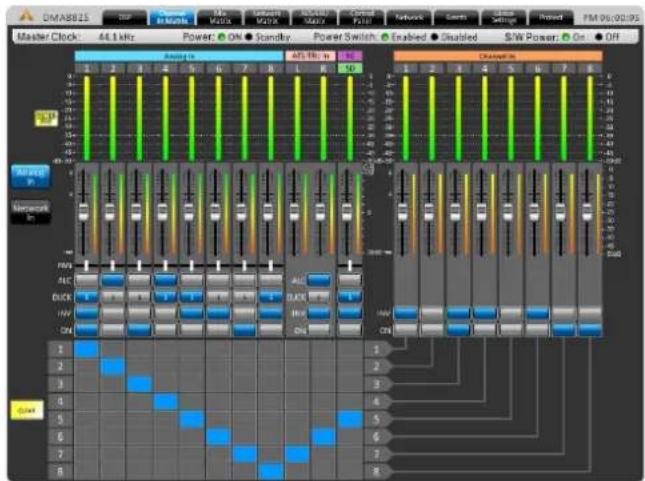
Meter Pre/Meter Post: This buttons sets all input sources to pre/post, determining whether or not they are affected by on-screen faders or not.
Analog In and Network In: Use these two buttons to view analog input sources connected via rear panel, as well as digital input sources from the Dante card.
PAN: This sliding control is used to adjust the left/right mix of the input signals.
ALC: Select this button to enable Automatic Level Control on the corresponding channel.
DUCK: Select this button to enable the ducking function on the corresponding channel.
INV: Select this button to invert the phase of the corresponding channel.
ON: Select this button to turn the corresponding signal on and off.
CLEAR: Clicking this button erases all assigned input/output routing.
Mix Matrix
In this page, you can assign which input sources are sent to the main mix outputs. All controls within the Mix Matrix are as the same as those found under the Channel In Matrix tab (page 10), except:
Analog In, Network In and Mix In: Use these three buttons to view analog input sources connected via rear panel, digital input sources from the Dante card and input signal processed in the Channel In Matrix tab.
Auto Mixer: When this function is enabled, ALC and DUCK work simultaneously.

Network Matrix
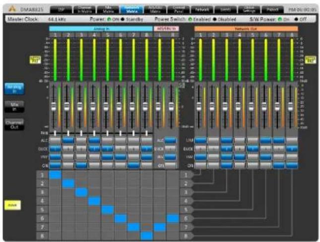
In this page, you can assign which kind of input source to be output via the connected Dante card. All controls are as same as controls under the Channel In Matrix tab (page 10), except:
Channel Out: To view output channel (the last output control in the signal path) effected by the Control Panel tab.
LIM: To enable/disable the built-in Limiter.
AES/EBU Matrix
Within the AES/EBU Matrix page, you can assign which input sources are sent to the AES/EBU output mix. All controls are as same as those under the Channel In Matrix tab (page 10) and Network Matrix tab (above).
AES/EBU signals can be synced using the WORD CLOCK input. For system clock settings, see page 15.

Control Panel
The control panel menu offers complete control of input channels. This menu includes level and gain controls, metering, and a host of other parameters that can be edited.
Channel Name: A pre-selected channel name can be viewed or edited in this screen.
Fader: The input level can be adjusted using this onscreen fader.
OUT: The input and output signal level of the channel can be viewed through these meters. They can be adjusted between pre- and post-fader meters.
GR: The gain reduction meter will provide a real-time indication of any reduction in gain applied by the internal DSP processes (including compressors-limiters, equalizers, etcetera).

Limiter: This button will activate the internal limiter function for the corresponding channel.
Pre/Post: This button allows you to adjust the output meter between a pre-fader and post-fader meter.
Duck: Activate the 'ducking' feature by pushing this button. The duck function can be activated as ducker 1, ducker 2, or off, the settings of which are decided by their respective menus.
INV: This button will invert the phase of the corresponding signal.
ON/OFF: This button will turn the corresponding channel on and off.
Bridged: When the speaker outputs are wired for bridge mode, users must push this button to bridge the outputs of the two channels.
Network
There are two pages under this tab.
Security
The menus found under this page may vary depending on the method of control being used.
Onboard Control
User Account Profile
You can create user accounts within this tab. Once a User Name and Password are defined, click "SAVE" to store.

Remote Control From PC
Enter necessary information to log in. Default values are:
IP Address: 192.168.10.200
User Name: USER 1
Password: ASYSTÉMS

Events
In the Events menu you will be able to set up a number of events to occur at a particular time of day. Events can range from simply powering on and off the device to activating audio files at a particular time.
Current Time & Current Date: Here users can set the current date and time. Click the Save button to set these settings. The date and time will be maintained within the DMA amplifier provided power is supplied to the device, whether active or in standby mode.
Time Format: Set the time format to 12/24 Hour time.
Schedule: Any Events already set will be displayed here.
Number: Assign a number to the event you're currently setting.

Subject: Provide a name or description to your event.
Location: Describe the location of where the event will occur.
Date: Set the date to begin your event.
Time: Set the time the event should occur, down to the very second.
Type: Select the type of event you are setting here. Available types include power change, channel mute, relay and SD card (typically for initiating audio playback).
Action: The action can be selected between on and standby.
Period: In the period section you will be able to set whether to set your event to occur once, weekly, daily, etc. You can also pick the days of the week for it to occur.
Global Settings
Analog In
Each of the analog inputs can have +48V of phantom power applied to it, ideal for condenser microphones. This menu also allows the user to trim the signal slightly if levels are too excessive.
A high-pass filter can also be added to each of the analog inputs to help remove stage rumble and other unwanted noise.

Global In On/Off
This menu provides each individual button input, including the analog inputs, network inputs, AES/EBU inputs and signal generator.

Ducker
The ducker allows a signal to temporarily attenuate below another signal when said signal activates the ducking feature. This is useful when making announcements and other such times when a signal needs to be heard clearly. The ducker can be activated on input and output channels by pushing the 'Duck' buttons found in the individual Matrix control pages. There are two of these 'duckers' total on the DMA.
Source: This is used to select the source of the duck function; i.e. the trigger signal. When the selected source's signal rises to a user-selected level, the currently selected 'duck' signals will attenuate at the selected level.
Threshold: This determines the level that the source signal needs to be before the ducking function will be activated.
Depth: This determines how much the selected 'duck' signals will be attenuated.

Attack: The attack time is the time it takes for the ducking feature to kick in after the source signal passes the selected threshold.
Release: The release time control will determine the time the 'duck' feature will remain active as the source signal drops back below the set threshold.
ALC – Auto Level Control
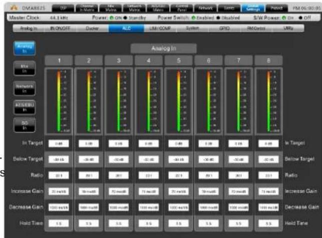
An autoleveler will allow users to dynamically change the level of an input or output signal to match a predefined level set by the user. The autolevel function can be activated for each individual mix in the matrix pages. The settings for these autolevelers can be found within this ALC menu.
In Target: The target level setting allows users to select the desired signal level for their autoleveler. All signals that are processed by the autoleveler will essentially aim for the target level.
Below Target: The below target threshold of the autoleveler is the point at which the autoleveler will kick in. Signals below the threshold will not be affected, but signals above will be have their gain increased.
Ratio: The ratio is the input level change in decibels to the output level change in decibels.
bar
OMASIS Master Clock 44.1 kHz Power On Standby Power Switch Enabled Disabled S/W Power On Off Analog In IN ON/OFF Docker ALC LSI/COMP System GPIO PMCycles LRF Analog In In Target 0.48 1.08 0.05 0.89 0.48 1.38 0.16 0.68 In Target Below Target -39.15 -28.48 -20.48 -31.05 -30.15 -20.45 -20.48 -21.05 Below Target Ratio 20.1 20.1 20.1 22.1 22.1 20.1 20.1 Ratio Increase Gain 20 ms/Hz 50 ms/Hz 70 ms/Hz 71 ms/Hz 70 ms/Hz 71 ms/Hz Increase Gain Decrease Gain 120 ms/Hz 100 ms/Hz 130 ms/Hz 130 ms/Hz 1400 ms/Hz 1300 ms/Hz 130 ms/Hz Decrease Gain Hold Time 5.5 5.5 5.5 5.5 5.5 5.5 Held Time Power Shift Enabled Disabled S/W Power On OffIncrease Gain: The increase gain determines the amount that the signal can be increased to meet the target level. This helps prevent sudden, alarming changes in audio level.
Decrease Gain: The decrease gain works the same as the decrease gain, but in reverse. It determines the amount a signal can be cut.
Hold Time: This determines the time the ALC will remain engaged after the signal falls back below the determined threshold.
LIM/COMP - Limiter/Compressor
This menu allows compressors and limiters to be applied to channel outputs, network outputs or AES/EBU outputs.
Limiter Threshold: This control determines the threshold for the limiter function. This means that no signal will surpass the selected threshold, being 'compressed' at a ratio of infinity:1.
Compressor Threshold: Use this control to set the threshold of the compressor function. Any signals that surpass the selected threshold will be compressed at the selected ratio.
Compressor Ratio: This control can be used to set the ratio for the compressor. The ratio is expressed as :

bar
Channel Out | Channel | 1 | 2 | 3 | 4 | 5 | 6 | 7 | 8 | | :--- | :--- | :--- | :--- | :--- | :--- | :--- | :--- | :--- | | Litter Threshold | 0.49 | 0.48 | 0.49 | 0.49 | 0.49 | 0.49 | 0.49 | 0.49 | | Compressor Threshold | 0.49 | 0.48 | 0.49 | 0.49 | 0.49 | 0.49 | 0.49 | 0.49 | | Compressor Ratio | 0.1 | 0.1 | 0.1 | 0.1 | 0.1 | 0.1 | 0.1 | 0.1 | | Attack | 1.0x | 1.0x | 1.0x | 1.0x | 1.0x | 1.0x | 1.0x | 1.0x | | Release | 832.0x | 832.0x | 832.0x | 832.0x | 832.0x | 832.0x | 832.0x | 832.0x | | Side Chain H.P.P. | OFF | OFF | OFF | OFF | OFF | OFF | OFF | OFF | Master Clock: All 1 kHz Power: On Standby Power Switch: Enabled Disabled S/W Power: On Off Analog In ReON/OFF Dasher AL US/CMF System OPD PM Control Llly Channel Out Litter Threshold Compressor Threshold Compressor Ratio Attack Release Side Chain H.P.P.Compressor Attack: This control adjusts the attack time of the compressor, essentially determining the time taken for the compressor to kick in after it passes the selected threshold.
Compressor Release: The release control determines the time the DMA will wait before disengaging the compressor when the signal bypasses the selected threshold.
Side Chain HPF: This allows users to set a high pass filter on these channels to essentially help rid these channels of low-frequency noise.
System
System Clock: This menu allows you to select a master clock source for digital devices. Selecting 44.1 or 48 kHz will set the DMA as the master clock source and determine the sampling rate. Selecting AES/EBU, Network, or Word Clock will set these as the master clock. Whenever a new clock source is selected, the ENTER button must be pushed to confirm.
Power Settings: There are three power settings on the DMA. The software power can be turned on and off, essentially enabling the DMA to be turned on and off via the software – including event scheduling. The hardware power can be selected on and off, essentially allowing the unit to be activated and deactivated using the hardwired switch on the front of the DMA.

Relay (GPIO)
The GPI – or General Purpose Interface – output is used to remotely control the DMA digital matrix amplifier. The relay page itself is used to setup the GPIs, including any and all remote controls connected to the unit.
The Preset panel is for use with the RM-4 remote preset controllers. The numbers in the "Port" field correspond with the ports on the rear of the DMA amplifier. The "No" field is the "Scene" number found in the utility tab. Any of your pre-saved scenes can be assigned to the available ports.

RM Control
This page offers a number of assignment options for the Asystems RM remote controls, specifically the RM-6E (sold separately). Each of the "Keys" listed in this page will correspond with a button on the RM-6E. Beside each key users will be able to select the function. This may be gain control, input/output mute, matrix mixing, etc. The last field will allow users to select a 'source' related to their selected function. For example, if "Gain Control" is selected, users will be able to select which input channel's gain is adjusted when that key is selected on the remote.
Up to 8 RM-6E remotes can be used at any one time. Each should be set to a different port to help identify it. Individual remotes can be locked using the corresponding buttons within the RM Control menu. Port settings for the RM-6E can be found on page 8.

Utility
All of the DSP processes can have their settings saved for later use. While there are a number of factory presets available, users are always encouraged to find their own settings and save them for later use. The DMA has onboard storage for a number of settings to be saved, or users can connect USB flash drives to save settings.
Also available in the Utility menu is a firmware update button. When a new version of firmware is available it can be installed using the "Update" button. Place the firmware update file on a formatted USB flash drive and insert it into a USB port. The "Update" button should take care of the rest. After the firmware is updated, the initialize button can be selected to reset the device. Save any settings (or "scenes") before initializing the system.

Protect
The protect menu gives real-time updates on the system performance. Everything from the system temperature to the output wattage is represented on this page. If the Protect LED on the front of the DMA amplifier lights up, this menu can be viewed to better understand the issue.

SPECIFICATIONS
| DMA8413 DMA8425 DMA8813 DMA8825 | ||||
| Low Z, Stereo Mode, all channels driven | RMS Power Output Per Channel | |||
| 8Ω, 20Hz-20kHz 1% THD | 80W 150W 80W | 150W | ||
| 4Ω, 20Hz-20kHz 1% THD | 130W 250W 130W | 250W | ||
| Low Z, Bridge Mode, all channels driven | RMS Power Output | |||
| 8Ω, 20Hz-20kHz 1%THD | 260W 500W 260W | 500W | ||
| 70.7V, 100V distributed output RMS | Power Output Per Channel | |||
| 20Hz-20kHz 1%THD, per channel | 130W 250W 130W | 250W | ||
| Models Available | 4Ω and 8Ω70.7 / 100V Constant Voltage | 4Ω and 8Ω70.7 / 100V Constant Voltage | 4Ω and 8Ω70.7 / 100V Constant Voltage | 4Ω and 8Ω70.7 / 100V Constant Voltage |
| Line Current Draw(all channels driven) | ||||
| Line Current, Standby mode | 190mA 190mA | 190mA 190mA | ||
| Line Current, Idle (no signal) | 540mA 540mA | 540mA 540mA | ||
| Line Current, Typical(1/8 power pink noise) | 2.85A 2.85A | 2.85A 2.85A | ||
| Line Current, Maximum(1/3 power sine wave) | 6.00A 6.00A | 6.00A | ||
| Signal to Noise(20Hz-20KHz, unweighted) | >110dB >110dB | >110dB >110dB | ||
| Distortion (SMPTE, typical) - 8 ohm load, 10dB below rated power | <0.5% <0.5% <0.5% | <0.5% | ||
| Distortion (THD-N, typical) -8 ohm load, 10dB below rated power, 20Hz-20kHz | <0.5% <0.5% <0.5% | <0.5% | ||
| Frequency Response | 20Hz-20kHz, +/-1dB 20Hz-20kHz, +/-1dB 20Hz-20kHz, +/-1dB 20Hz-20kHz, +/-1dB | |||
| Damping Factor (8 ohm load,<1kHz) | >250 >250 >250 | >250 | ||
| Input Impedance | 20K Ohm, balanced 20K Ohm, balanced 20K Ohm, balanced 20K Ohm, balanced | |||
| Maximum Input Level | +24dB +24dB +24dB +24dB | |||
| Cooling | Temperature dependent speed-controlled axial fan | |||
| Control Network | Onboard, compatible with standard 100MB Ethernet hardware | |||
| Front Panel Indicators | 8 x Clip, -10dB, -20dB, Signal, Bridge (per pair) Power, Standby, Protect, Power Disable | |||
| Attenuators | 8 x front panel, software, and remote | |||
| Input Connections | Euroblock & Stereo RCA | Euroblock & Stereo RCA | Euroblock & Stereo RCA | Euroblock & Stereo RCA |
| Output Connections | Euroblock | Euroblock | Euroblock | Euroblock |
| Amplifier Protection | Inrush current limitation, temperature monitoring, output over-current protection, mains fuses | |||
| Power Supply (Region Dependent) | 120VAC, 230VAC, 50/60Hz,15A Edison cable | |||
| Dimensions (W x H x D) | 483 x 89 x 394 mm(19" x 3.5" x 15.5") | 483 x 89 x 394 mm(19" x 3.5" x 15.5") | 483 x 89 x 394 mm(19" x 3.5" x 15.5") | 483 x 89 x 394 mm(19" x 3.5" x 15.5") |
| Weight | 9.53 kg (21 lbs) | 9.53 kg (21 lbs) | 9.53 kg (21 lbs) | 9.53 kg (21 lbs) |
PARAMETERS
| Function Parameter Range | ||
| Compressor / Limiter | Compressor Threshold -50 dB to 0 dB | |
| Ratio 1:1 to 20:1 | ||
| Limiter Threshold -50 dB to 0 dB | ||
| Output Gain 0 dB to 18 dB | ||
| Attack / Release 1 ms to 8 seconds | ||
| Gate | Threshold -50 dB to 0 dB | |
| Range -90 dB to 0 dB | ||
| Attack / Hold / Release 1 ms to 8 seconds | ||
| Expander | Threshold -50 dB to 0 dB | |
| Ratio 1:1 to 20:1 | ||
| Attack / Release 1 ms to 8 seconds | ||
| Delay | Delay Time (mS) 0.0 to 680.0 ms | |
| Delay Time (meters) 0.0 to 245.5 | ||
| Delay Time (feet) 0.0 to 805.4 | ||
| Temperature (C) 0° to 50° | ||
| Temperature (F) 32° to 122° | ||
| 4-band Equalizer | Type | BPF, Notch, Peak, HPF, LPF, High Shelf, Low Shelf |
| Gain | -18 dB to +18 dB | |
| Frequency | 20 Hz to 20 kHz | |
| Q | 0.1 to 10 | |
| 31-band Graphic EQ | Frequencies | 20 Hz to 20 kHz |
| Range | -12dB to +12dB | |
| Q | 1.6 to 10 | |
| Filters | Type | HPF (6 dB, 12 dB, 18dB, 24dB), LPF (6 dB, 12 dB, 18dB, 24dB), High Shelf, Low Shelf, Peak, APF, BPF, Notch |
| Gain | -18 dB to +18 dB | |
| Frequency | 20 Hz to 20 kHz | |
| Q | 0.1 to 10 | |
| Feedback Silencer | Threshold -50 dB to 0 dB | |
| Release Time | 10 sec/dB to 300 sec/dB | |
| Gain | -20 dB to 0 dB | |
| Frequency | 20 Hz to 20 kHz | |
| Q | 4.5 to 10 | |
| VCA | Gain | -∞ to 6 dB |
| Automatic Level Control | In Target 0 dB to -50 dB | |
| Below Target -30 dB to 0 dB | ||
| Ratio | 1:5~20:1 | |
| Increase Gain | 40ms/dB to 1000ms/dB | |
| Decrease Gain | 1000ms/dB to 40ms/dB | |
| Hold Time | 0s to 10s | |
| Ducker | Source | Analog 1 to 8, Network 1 to 8, AES/EBU |
| Threshold -50 dB to 0 dB | ||
| Depth | -80 dB to 0 dB | |
| Attack / Release | 0.2s to 20s | |
| Crossover | HPF / LPF Type | Butterworth 12dB, 18dB, 24dB |
| HPF / LPF Frequency | 20 Hz to 20 kHz | |
| Signal Generator | Sine Wave Frequencies | 20Hz to 20KHz |
| Sweep Wave Start/End Frequencies | 20Hz / 20KHz | |
| Sweep Wave Hold Time | 50ms to 2000ms | |
| Signal Level Range -60dB to -10dB |
ÍNDICE
INTRODUCCIÓN....21
CARACTERÍSTICAS....21
natural_image
Front view of a server rack with indicator lights and a logo, mounted on two side rails (no text or symbols visible)4.2 CONEXIÓN


3. CONTROL REMOTO PROGRAMABLE RM-6E
Eventos/Events

ALC – Auto Level Control
bar
Analog In | 1 | 2 | 3 | 4 | 5 | 6 | 7 | 8 | |---|---|---|---|---|---|---|---| | In Target | 0.49 | 0.49 | 0.49 | 0.49 | 0.49 | 0.49 | 0.49 | | Below Target | -34.19 | -34.45 | -35.48 | -37.08 | -39.09 | -39.49 | -39.49 | | Ratio | 20.1 | 20.1 | 20.1 | 20.1 | 20.1 | 20.1 | 20.1 | | Increase Gain | 35 mV/d | 35 mV/d | 35 mV/d | 35 mV/d | 35 mV/d | 35 mV/d | 35 mV/d | | Decrease Gain | 100 mV/d | 100 mV/d | 100 mV/d | 100 mV/d | 100 mV/d | 100 mV/d | 100 mV/d | | Hold Time | 5.5 | 5.5 | 5.5 | 5.5 | 5.5 | 5.5 | 5.5 | Analog In Power: On Standley Power Switch: Enabled Disabled S/W Power: On Off Analog In: IN ON/OFF Docker ALC LM/COMP System GPO IM/Control Lbps In Target Below Target Ratio Increase Gain Decrease Gain Hold TimeUtility
Protect
natural_image
Abstract black geometric logo resembling the letter 'A' with a stylized triangular shape and curved extensions (no text or symbols)SYSTEMS
www.asystems-sys.com

- IMPORTANT SAFETY INSTRUCTIONS
- INTRODUCTION
- FEATURES
- CONTROLS AND I/O
- Mounting Holes
- Output Level Control Knobs
- OUT LED
- BRIDGE LED
- Cooling Inlet Vents
- Reset Button
- Indicators
- Power Switch
- REAR PANEL
- AC Power Connector
- AES/EBU Connector
- RS-232 Connector
- VGA Connector
- SD Card Slot
- WCLK Connector
- USB Ports
- SPEAKER OUTPUTS (Amplified Output)
- PERIPHERAL Connector
- PRESET RECALL Connector
- REMOTE LEVEL CONTROL Connector
- INPUT Connectors
- OUTPUT Connectors
- DIGITAL I/O Expansion Card Slot
- ETHERNET Connector
- INSTALLATION AND SETUP
- RACK MOUNTING
- CONNECTIONS
- AUDIO INPUT
- Balanced
- Unbalanced
- AUDIO OUTPUT
- AMPLIFIED OUTPUTS
- AUX OUTPUTS
- DIGITAL I/O EXPANSION CARD
- ONBOARD CONTROL
- REMOTE CONTROL
- RM-2VR REMOTE LEVEL CONTROL
- RM-4 REMOTE PRESET RECALL CONTROL
- RM-6E PROGRAMMABLE REMOTE CONTROL
- WINDOWS-BASED PC
- CONTROL SOFTWARE
- DSP
- Channel In Matrix
- Example:
- Mix Matrix
- Network Matrix
- AES/EBU Matrix
- Control Panel
- Network
- Security
- User Account Profile
- Remote Control From PC
- Events
- Global Settings
- Analog In
- Global In On/Off
- Ducker
- ALC – Auto Level Control
- LIM/COMP - Limiter/Compressor
- System
- Relay (GPIO)
- RM Control
- Utility
- Protect
- ÍNDICE
- CONEXIÓN
- CONTROL REMOTO PROGRAMABLE RM-6E
- Eventos/Events
Brand : PHONIC
Model : DMA8825
Category : Receiver