
S4101-16ET2GF-240-C - Network switch Dahua Technology - Free user manual and instructions
Find the device manual for free S4101-16ET2GF-240-C Dahua Technology in PDF.


| Product Type | Network Switch |
| Brand | Dahua Technology |
| Model | S4101-16ET2GF-240-C |
| Ports | 16 x 10/100/1000Base-T Ethernet, 2 x 1000Base-X SFP Fiber |
| Power over Ethernet | IEEE 802.3af/at compliant, Total PoE Budget: 240W |
| Switching Capacity | 36 Gbps |
| Forwarding Rate | 26.78 Mpps |
| MAC Address Table | 8K entries |
| VLAN Support | IEEE 802.1Q VLAN up to 4096 VLAN groups |
| Management | Web GUI, SNMP v1/v2c/v3, CLI via console port |
| Dimensions (W x D x H) | 17.3 x 8.3 x 1.7 inches (440 x 210 x 44 mm) |
| Weight | Approx. 7.5 lbs (3.4 kg) |
| Power Supply | Internal, AC 100-240V, 50-60Hz, 3.5A |
| Power Consumption | Max: 280W (including PoE) |
| Operating Temperature | 32°F to 104°F (0°C to 40°C) |
| Storage Temperature | -40°F to 158°F (-40°C to 70°C) |
| Humidity | 5% to 90% non-condensing |
| Cooling | Internal fan with intelligent speed control |
| LED Indicators | Power, System, Per-port link/activity, PoE status |
| Mounting | Rack-mountable (1U), desktop placement also supported |
| Safety Certifications | CE, FCC, RoHS |
| Care and Cleaning | Wipe with dry cloth; avoid liquids and solvents |
| Spare Parts and Repairability | Replacement power supply and fans available; visit support website |
| General Information | Layer 2 managed switch designed for surveillance and enterprise networks |
Frequently Asked Questions - S4101-16ET2GF-240-C Dahua Technology
User questions about S4101-16ET2GF-240-C Dahua Technology
0 question about this device. Answer the ones you know or ask your own.
Ask a new question about this device
Download the instructions for your Network switch in PDF format for free! Find your manual S4101-16ET2GF-240-C - Dahua Technology and take your electronic device back in hand. On this page are published all the documents necessary for the use of your device. S4101-16ET2GF-240-C by Dahua Technology.
USER MANUAL S4101-16ET2GF-240-C Dahua Technology
natural_image
Abstract geometric composition with gray and blue color blocks (no text or symbols)V1.2.0
Foreword
General
This manual introduces the functions and operations of the DoLynk Care platform (hereinafter referred to as the "Platform"). Read carefully before using the platform, and keep the manual safe for future reference.
Safety Instructions
The following signal words might appear in the manual.
| Signal Words Meaning | |
 WARNING WARNING | Indicates a medium or low potential hazard which, if not avoided, could result in slight or moderate injury. |
 .CAUTION .CAUTION | Indicates a potential risk which, if not avoided, could result in property damage, data loss, reductions in performance, or unpredictable results. |
 TIPS TIPS | Provides methods to help you solve a problem or save time. |
 NOTEProvides additional information as a supplement to the text. NOTEProvides additional information as a supplement to the text. | |
Revision History
| Version | Software Version | Revision Content | Release Time |
| V1.2.0 V1.200 | .0000001.0 | Update the content of login, register, and changing password; Add company certification. | August 2023 |
| V1.1.0 V1.100 | .0000000.0 | Add switch configuration, including switch settings, port settings VLAN and link aggregation. Add alarm hub configuration and accessories management. | July 2023 |
| V1.0.1 V1.017 | .0000000 | Add passive infrared camera configuration, binding Converter account, UTC settings and more. | April 2023 |
| V1.0.0 | V1.000.0000015.0 | First release. | September 2022 |
Privacy Protection Notice
As the device user or data controller, you might collect the personal data of others such as their face, fingerprints, and license plate number. You need to be in compliance with your local privacy protection laws and regulations to protect the legitimate rights and interests of other people by implementing measures which include but are not limited: Providing clear and visible identification to inform people of the existence of the surveillance area and provide required contact information.
About the Manual
- The manual is for reference only. Slight differences might be found between the manual and the product.
- We are not liable for losses incurred due to operating the product in ways that are not in compliance with the manual.
- The manual will be updated according to the latest laws and regulations of related jurisdictions. For detailed information, see the paper user's manual, use our CD-ROM, scan the QR code or visit our official website. The manual is for reference only. Slight differences might be found between the electronic version and the paper version.
- All designs and software are subject to change without prior written notice. Product updates might result in some differences appearing between the actual product and the manual. Please contact customer service for the latest program and supplementary documentation.
- There might be errors in the print or deviations in the description of the functions, operations and technical data. If there is any doubt or dispute, we reserve the right of final explanation.
- Upgrade the reader software or try other mainstream reader software if the manual (in PDF format) cannot be opened.
- All trademarks, registered trademarks and company names in the manual are properties of their respective owners.
- Please visit our website, contact the supplier or customer service if any problems occur while using the device.
- If there is any uncertainty or controversy, we reserve the right of final explanation.
Table of Contents
Foreword....
1 Introduction....1
2 Signing Up and Login 2
2.1 Signing Up....2
2.2 Login ....3
2.3 Changing Password....4
3 Company Certification....5
4 Home....7
4.1 Home Page....7
4.2 Entrusting Tasks....8
4.2.1 Viewing the List....8
4.2.2 Processing the Entrusting Tasks 9
4.3 Error Tasks....11
4.3.1 Viewing the Error Task List....11
4.3.2 Processing the Error Tasks....11
4.4 Device Overview ....12
4.5 Error Overview....13
5 Site Management 14
5.1 Site List....14
5.2 Adding Sites....16
5.3 Device Management 16
5.3.1 Adding Devices....17
5.3.2 Importing Devices in Batches....18
5.3.3 Delivering Devices 18
5.3.4 Applying for Permissions....18
5.3.5 Moving Devices to Other Sites 19
5.3.6 Live View Page....19
5.3.7 Managing Network Transmission Devices....20
5.3.7.1 Viewing Topology ......20
5.3.7.2 Configuring Switches....22
5.3.7.3 Viewing Alarm Messages ......25
5.3.7.4 Configuring Port 25
5.3.7.5 Configuring Device VALN 28
5.3.7.6 Configuring Port VLAN 28
5.3.7.7 Configuring Link Aggregation 29
5.3.7.7.1 Configuring Load Balancing....30
5.3.7.7.2 Adding Link Aggregation ....30
5.3.8 Managing Alarm Hubs....32
5.3.8.1 Configuring Alarm Hub....34
5.3.8.1.1 Device Settings .... 34
5.3.8.1.2 User Management....36
5.3.8.1.3 Arming/Disarming Settings....38
5.3.8.1.4 Alarm Settings....39
5.3.8.1.5 Network Settings 42
5.3.8.2 Viewing Messages....43
5.3.8.3 Managing Accessories....44
5.3.9 Alarm Receiving Center Service....45
5.3.9.1 Creating Converter Accounts....45
5.3.9.2 Applying for Security Service....47
5.3.9.3 Disabling the Converter Account ....48
6 Device Maintenance....49
6.1 Health Center....49
6.2 Health Diagnosis 49
6.3 Health Reports ....50
7 Customer Management....51
7.1 Viewing Customer List ....51
7.2 Viewing the Device Information ....51
8 Company Management 52
8.1 Viewing Company Information....52
8.2 Managing Operators....53
9 Service Management 56
9.1 Service Market ....56
9.2 My Service 56
9.2.1 Package Information....56
9.2.2 Order Information....57
Appendix 1 Accessory Settings....58
Appendix 1.1 Outdoor Siren....58
Appendix 1.2 Wireless Keypad....58
Appendix 1.3 Glass Break Detector....59
Appendix 1.4 PIRCam....59
Appendix 1.5 Door Detector....60
Appendix 1.6 Keyfob....60
Appendix 1.7 Panic Button (Simple)....61
Appendix 1.8 Updated Door Detector....61
Appendix 1.9 Panic Button (Double)....62
Appendix 1.10 Alarm Repeater ....62
Appendix 1.11 PIR Sensor....62
Appendix 1.12 Wireless Input Expander 1.0....63
Appendix 1.13 Wireless Input Expander 2.0....63
Appendix 1.14 Wireless Relay....64
Appendix 1.15 Wireless Dual-tech....64
Appendix 1.16 Wireless Water Leak Detector ....65
Appendix 1.17 Indoor Siren....65
Appendix 2 Cybersecurity Recommendations....66
1 Introduction
DoLynk Care provides services, such as device management and alarm maintenance for installers to deliver, entrust, and manage the terminal devices, in order to strengthen the relationship with customers. Third-level SI users can be covered relying on the SMB business types and installer channels. To further develop overseas business, DoLynk Care helps the company transform from device supplier to solution provide. As required by the actual needs, DoLynk Care comes with cloud platform embedded in its system, allowing it to cover many areas, such as access, attendance, video intercom, retails, and parks, to diversify development.
2 Signing Up and Login
2.1 Signing Up
For the first time to log in to DoLynk Care, you must create an account first. The sign up methods include personal account registration and GSP invitation registration.

You can log in to the platform with the accounts of the systems including Partner app and DoLynk Dashboard.
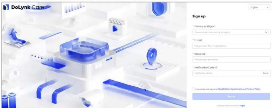
Personal account registration
You can sign up through registration portal of the platform login page. The registered account is a personal account. If you need to use features such as entrusting devices and purchasing service packages, you need to get authenticate your company after logging in.
- Enter the platform address in the browser, and then press Enter.
- Click Sign up to create an account.
- Select the country or region, enter the email address and password, and then click Send to obtain the verification code.
- Enter the verification code that was sent to the registered email, and then read and select I have read and agree to Registration Agreement and Privacy Policy. Click Sign up.

If the browser language is Thai, you can register an account with your mobile phone number to obtain the verification code.
Figure 2-1 Personal account registration
GSP Invitation Registration
The GSP system triggers and sends a registration link to your email. You can register for a DoLynk Care account by clicking the link. The account registered through the GSP invitation is an enterprise account.
-
Click the link received in the email to go to the registration page.
-
The system automatically fills in the customer's email address, company name, country, province, city and company address, and you cannot modify the information. Enter the invitation code, set the password, and then click Send to obtain the verification code.

You can obtain the invitation code from your superior distributor.
- Enter the verification code obtained from the registered email, and then read and select I have read and agree to Registration Agreement and Privacy Policy. Click Sign up.

The registration link is valid for 3 days. If the link is invalid, you can ask your sales to send an invitation registration email again.
2.2 Login
Procedure
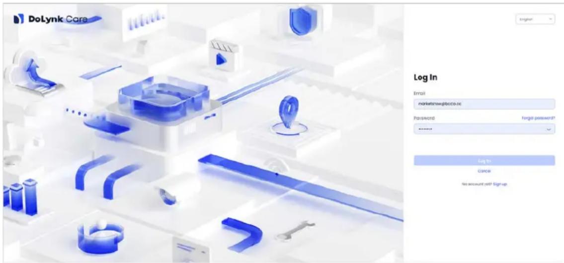
Step 1 Open the browser, enter the web address, and then press the Enter key.
Step 2 Enter Email and Password, and then click Log in.

- When selecting the language as Thai, you can log in with your phone number.
- If you log in using your personal account from Partner app, you need to select a country when you log in for the first time.
- If you log in using the company account from Partner app, you need to select a role, administrator or employee to log in for the first time. If the selected role is an employee, you must first contact the administrator to create an employee account. For details, see "8.2 Managing Operators".
Figure 2-2 Log in
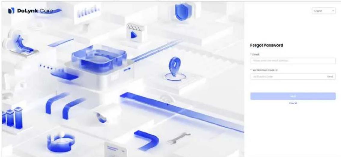
Step 3 (Optional) If you forget your password, click Password page.
Forgot password?, and enter the Forgot
1) Enter the email address, and then click send to obtain the verification code.
2) Enter the verification code, and then click Next.
3) Enter your original password and new password, and confirm it, and then click OK.

- Click DoLynk Care on the upper right corner of the page to go to the portal page.
- If the account is from another system such as Partner app and has never logged in to DoLynk Care before, the Forgot password? is not supported. You have to log in to DoLynk Care at least once.
When selecting the language as Thai, you can reset your password with your phone number.
Figure 2-3 Forgot password
2.3 Changing Password
After logging in to DoLynk Care, you can change the password of your current account.
Procedure
Step 1 Log in to DoLynk Care.
Step 2 Click the account name at the upper right corner of the page, and then select Change Password.
Step 3 Enter the old password and the new password according to the requirements prompted on the page, and then confirm the new password.

Click next to the password to display the password.
Step 4 Click OK
3 Company Certification
When you log in to a personal account for the first time, you must get company certification to become a company user. By default, company account users who are invited to register through GSP invitation link do not need to be certified.
Procedure
Step 1 Log in to DoLynk Care.
Step 2 Select Company, and then click Authenticate on the prompt page to go to the company certification page.
Step 3 Configure the parameters.
Table 3-1 Company Certification
| Parameter | Description | Country | Attribute |
| Company name Enter the company name | Note applicable only to North America | Required | |
| Country or Region | Select a country or region. You can only select the province or region of the country where the current account is registered. | All Required | |
| Company Address | Enter the company address. | All | Required |
| Tax Number | Enter the company tax number. | All Required | |
| Invitation Code | Enter the agent invitation code. | General | Vietnam, South Africa and Thailand are not required. Other countries and regions are required. |
| Distributor Registration Code | Enter the distributor registration code | Applicable only to North America | Required |
| Company logo | Click to upload the company logo as prompted. | General Required | |
Step 4 Click OK.
Related Operations
- After you have applied for a company certification, please wait for the sales to review. The certificate status is displayed as Being Authenticated. The company information cannot be modified in this status.

If the region of the application company is in North America, the distributor registration code is required. After entering the code and being verified, the account will be certified successfully without review.
- Accounts that are being reviewed or not certified cannot deliver lent devices, entrust devices,
view the live video, play the recordings or purchase service packages. However, you can add devices and sites.
- After the verification is passed, the certificate status is displayed as Already Authenticated. You can click ☐ to modify the company information, including company address, tax number and logo.
- If the review fails, the certificate status is displayed as Authentication failed. You can fill in the company information to apply for company certification again.
4 Home
4.1 Home Page
Figure 4-1 Home page
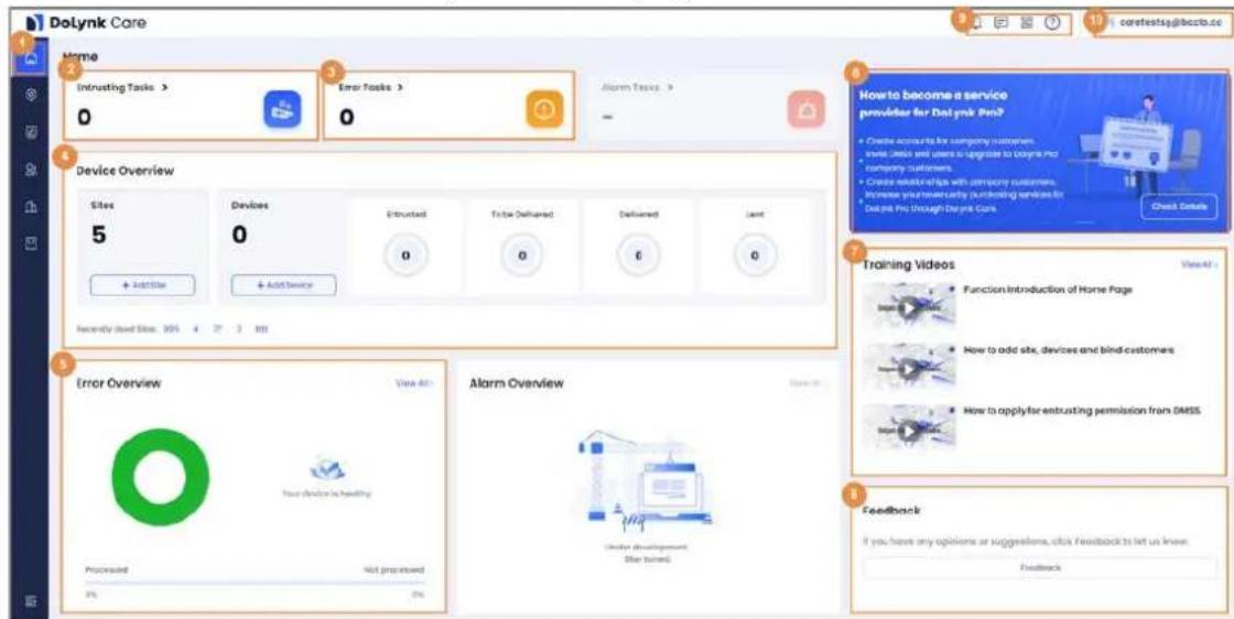
Table 4-1 Introduction
| No. Name | Description | |
| 1 | Navigation bar | Displays 6 modules ofHome, Sites, Health Center, Customers, company and Services. Health Center includes Health Center, Health Diagnosis, and Health Report. Services includes Service Market and My Service. |
| 2 | Entrusting tasks | Click the Entrusting Tasks card area to enter the Entrusting Tasks page. For details, see "4.2 Entrusting Tasks". |
| 3 | Error tasks | Click the Error Tasks card area to enter the Error Tasks page. For details, see "4.3 Error Tasks". |
| 4 | Device overview | Display the sites and the devices. For details, see "4.4 Device Overview". |
| 5 | Error overview | Displays the errors of the devices. For details, see "4.5 Error Overview". |
| 6 | Advertisement | Display the advertising information of the product. You can scan the QR code to upgrade the app. |
| 7 | Training videos Display the training videos. | |
| 8 | Feedback | Click Feedback to give suggestions and advice. |
| 9 | : Task center. You can check all the new messages here.: Notification center.◇ The messages related to the interactions with DMSS will be displayed in Personal Message.◇ The messages related to DoLynk Dashboard will be displayed in System Message.: Scan the QR code with the DMSS app to entrust devices.: Click to view User Manual, Datasheet, FAQ, Device Troubleshooting Guide, and Wizard. | |
| 10 | Click to manage account, change password, use activation code, view operation logs and log out.Click Account Management to edit username, upload profile photo, delete the account or delete a device.⚠️After deletion, the user data cannot be restored. Be cautious. BookYou cannot delete the account when there are sites, devices, operator accounts or service packages in using.Click Change Password to change the login password.Click Use Activation Code to enter the activation code to redeem services.Click Operation Log to view the logs. You can select the operator, operation and time to view and export the operation logs.Click Exit to log out the current account and return to login page. | |
4.2 Entrusting Tasks
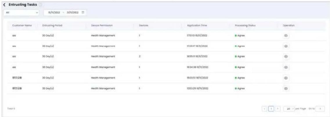
You can view the entrusting task list, and operate the tasks uploaded from DMSS app.
4.2.1 Viewing the List
Procedure
Step 1 Select Home > Entrusting Tasks, and then view the list of entrusting tasks.
Step 2 Select from processing status, start time, and end time, and then view the tasks.

Processing Status includes All, Not processed, Agree and Rejected.
Figure 4-2 Entrusting tasks
4.2.2 Processing the Entrusting Tasks
You can process the tasks uploaded from the app.
Prerequisites
You have scanned the entrusting code with DMSS app, and entrust the devices to DoLynk Care.

If the DMSS account is registered in the Imou platform, you need to upgrade the account then entrust the devices.
Procedure
Step 1 Select Home > Entrusting Tasks, and then view the list.

When you start an entrusting task in DMSS, you can click 🔒 to view the message notification of the entrusting.
Step 2 Select from the Processing Status as Not processed.
Step 3 Click, and then enter the Entrusting Review page.
Step 4 You can view the Email, Entrusting Period, Device Permission, Application Time, Device Name and Device SN.
Step 5 Verify the entrusting tasks.
Figure 4-3 Entrusting verify
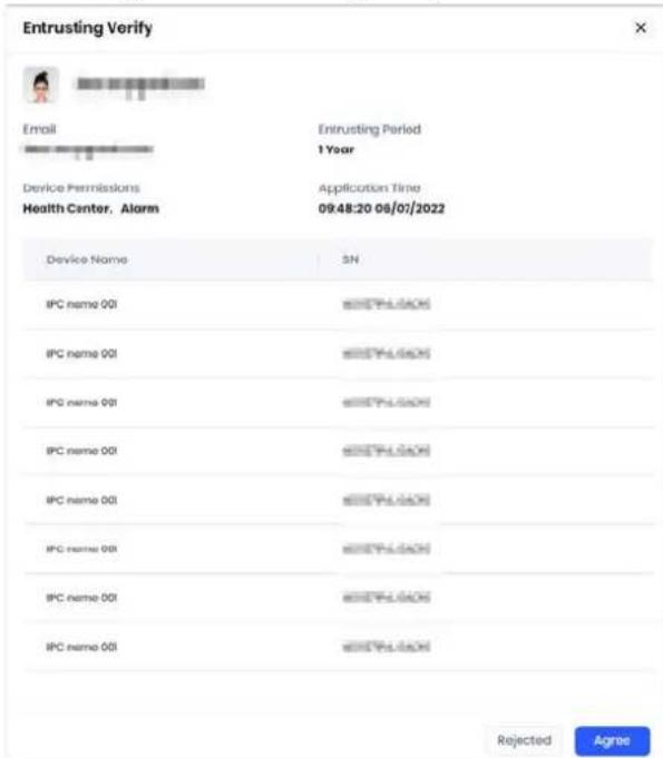
- Reject the entrusting task: Click Rejected, and the Processing Status is displayed as Rejected.
-
Agree the entrusting task: Click Agree, and the Processing Status is displayed as Agree.
-
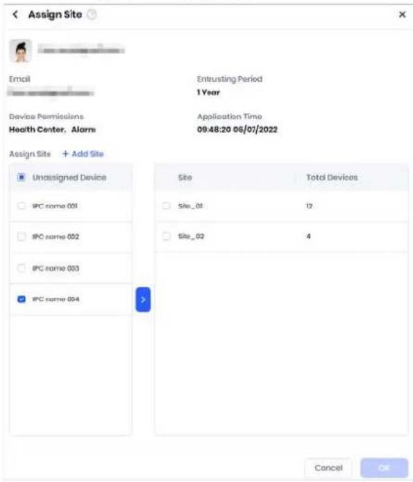
Click Agree, and enter the Assign Site page.
- Select devices from the Unassigned Device box, and then click to assign the devices to sites.
- Click OK.
Figure 4-4 Assign site
4.3 Error Tasks
You can view the error task list and process the error tasks.
4.3.1 Viewing the Error Task List
Procedure
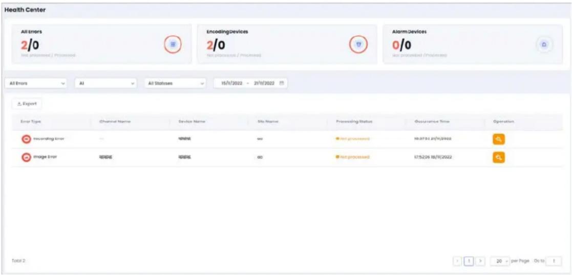
Step 1 Select Home > Error Tasks, and then enter the Health Center page to view the list of the error tasks.
Step 2 Select the error type, site, processing status, and time to view the error tasks.
- Encoding devices errors include Abnormal Voltage, Disk Error, Recording Error, Image Error, Channel Offline and Abnormal Device Temperature.
- Alarm device error include Abnormal Voltage, Accessory Offline and RF-HD Error.
- Processing status includes All Statuses, Processed and Not processed.
Figure 4-5 Error task list
Related Operations
To export the report of unprocessed errors, you can click Export.
4.3.2 Processing the Error Tasks
You can process the error tasks.
Procedure
Step 1 Select Home > Error Tasks, and then enter the Health Center page.
Step 2 Select Processing Status as Not processed.
Step 3 Click, and then enter the Fix Errors page.
Step 4 You can view the Device Name, Email, Device SN and Occurrence Time.
Step 5 Enter the Operation Details, and then click Process.
Figure 4-6 Fix error
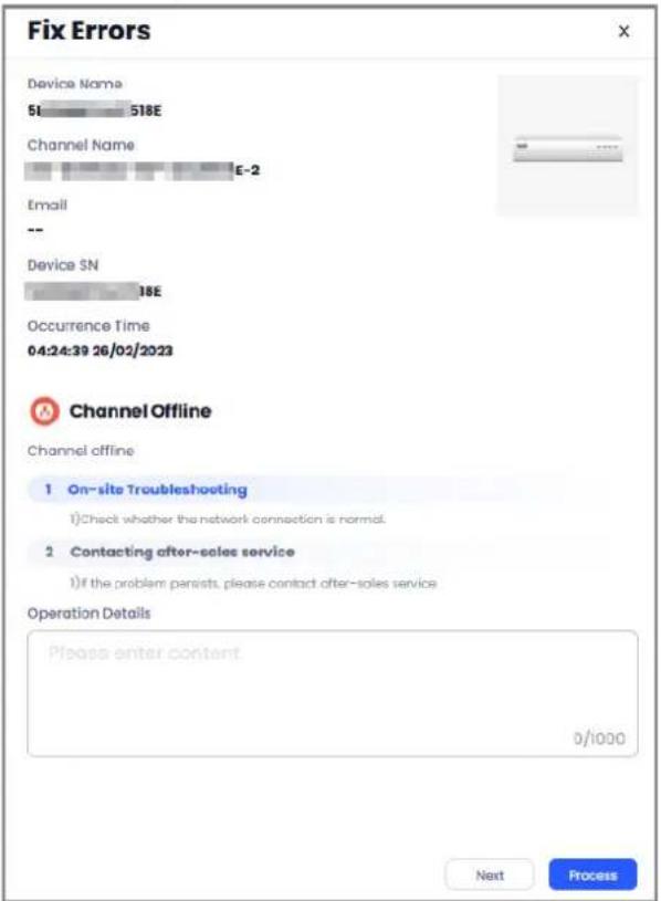
Step 6 After the process, the device will automatically start self-check.
After the self-check is completed, the Processing Status will be Processed.
4.4 Device Overview
Select Home > Device Overview, to view the site number and device number.

- Recent Used Sites displays the recently used 5 sites, and helps you quickly enter the site.
- The Devices column displays numbers of devices of different statuses, including Entrusted, To be Delivered, Delivered, Lent.
-
Add Site.
-
Click Add Site, and then configure the site parameters.
Table 4-2 Parameters description of adding site
| Parameter Description | |
| Site Name | Required field, enter the site name. |
| Customer Email | Enter the customer email address.Please enter the email address of the account that your customer has registered on DMSS app. DoLynk Care will verify it. |
| Customer Name Enter the | customer name. |
| Operator | Select an operator added by the current DoLynk Care account, to bind the site and customer. Click add operator to add a new operator. For detailed information, see "8.2 Managing Operators". |
| Time Zone Select the time zone of the site. | |
| DST | Select DST on or off. The time will be adjusted automatically after DST on. |
| Phone Number | Enter the phone number of the customer. |
| Address | Enter the address information that you configured when registered the DoLynk Care account. |
- Click OK。
- Add Device.
- Click Add Device.
Table 4-3 Parameters description of adding device
| Parameter Description | |
| Device name Enter the name of the device. | |
| Device SN | You need to enter the SN number manually when using the webpage. You can scan the code on device when using the app. |
| Device password Enter the password of the device. | |
| Add the device to | You can add the device to existing site or new site. If you select adding the device to a new site, you need to create the site first. |
| Select site | If add the device to existing site, you can select a site in the list. |
- Click OK.
4.5 Error Overview
You can view the statistics of errors based on types, error trend within a specific period and error processing statistics by operator.
Procedure
Step 1 Select Home > Error Overview > View All, and then enter the Error Overview page.
Step 2 Select a period of time to filer the data.

- The page displays the data in last 7 days by default.
- You can quickly filter the data by selecting Last 7 Days, Last 30 Days, Last 6 Months and Last Year.
5 Site Management
5.1 Site List
Click Sites to view the site list.
- All the sites are displayed in the format of cards, with the information including site name, customer name, operator, site address, and device numbers of different statuses. On the upper right corner of the page, you can enter the site name, customer name or operator in the to search for the sites.
- Hover the mouse over the site card, and then click 📋 to edit the site.
If the customer email is configured when adding the site, the customer email cannot be modified.
If you changed the time zone of the site, all the time zone of the devices in this site whose status are To be Delivered will be changed at the same time.
Figure 5-1 Edit site
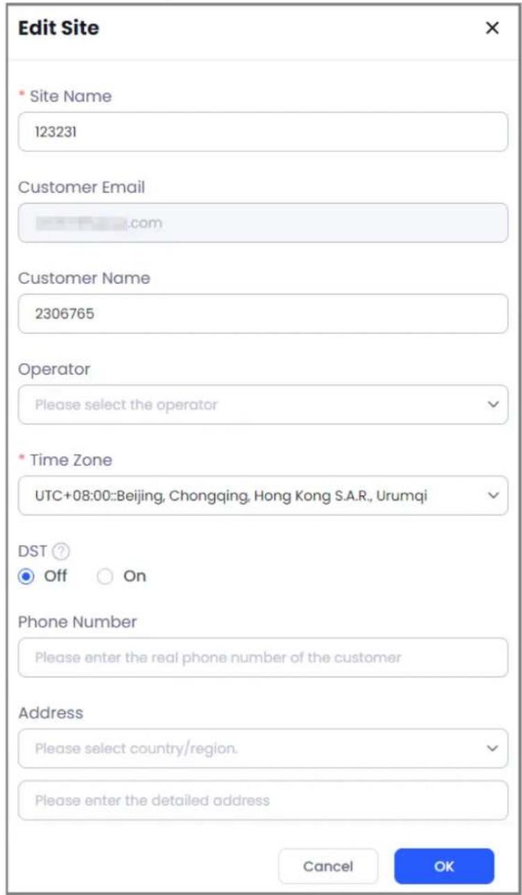
- Hover the mouse over the site card, and then click to delete the selected site.

Sites can only be deleted when they are not bound to devices in the entrusted, to-be-delivered, delivered and lent status.
5.2 Adding Sites
For the detailed information, see "4.4 Device Overview".
5.3 Device Management
Click a site to view all the devices under the current site. You can also add devices, deliver devices, import devices in batches, apply for permissions, delete and export devices in batches.
Procedure
Step 1 Click Sites, and then select a site to enter the device list page. You can view all the devices under the current site.
Step 2 You can view Device Name, Device Type, Device Status, Health Status, and Authorization Status.

- For the delivered devices, you can apply for permissions and delete them.
- Except network transmission devices, other to-be-delivered devices can be delivered and deleted.
- Live videos are available for NVRs and IPCs that are in the to be delivered status. You can only view the details for other devices.
- Lending alarm hubs support cancelling lending and viewing details, but cannot be deleted.
- Network transmission devices and alarm hubs support viewing the home page of the device.
- Network transmission devices and alarm hubs can be remotely configured.
Step 3 Select the device type to display the results.

Device Type includes All, Encoding Devices, Alarm Devices, Network Transmission Devices, and Access Control and Video Intercom Devices.
Step 4 Click 📋 to filter the results according to authorization status.

Authorization Status includes All, To be Delivered, Entrusted, Delivered, and Lent.
Figure 5-2 Device list
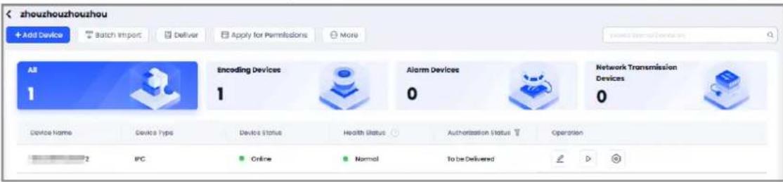
Related Operations
- Export device list: Select More > Export, and then export the information list of all devices, including device SN, device name, device model, and device type.
- Search for device: Click device based on device name, and then enter the device name and device SN to search for devices.
- Edit device: Click to enter the Edit Device page, and then modify the device name or delete the device.
- For the network transmission devices, hover the mouse to More, and then select Topology to view the topology of the network transmission device.
5.3.1 Adding Devices
Procedure
Step 1 Click Sites, select a site and then enter the device list.
Step 2 Click Add Device, and enter the Add Device page.
Step 3 Enter Device Name, Device SN and Device Password, and then click OK.
Figure 5-3 Add device under site
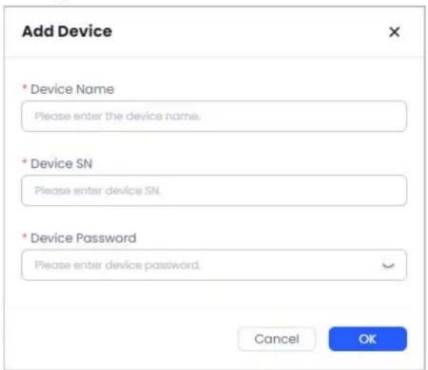

- You cannot add the device which has been bound to a customer.
- If the added device is offline, then it will go to the network connection configuration page of the device.
5.3.2 Importing Devices in Batches
You can import devices in batches.
Procedure
Step 1 Click Sites, select a site and then enter the device list.
Step 2 Click Batch Import, and enter the Batch Import page.
Step 3 Click Download Template to obtain the template. Fill in the template, and then click Upload File or drag the file to upload the device information.
Step 4 Click OK.
5.3.3 Delivering Devices
You can deliver devices to customers. Network transmission devices cannot be delivered.
Procedure
Step 1 Click Sites, select a site and then enter the device list.
Step 2 Click Deliver to enter the Deliver Device page.
Step 3 Enter the customer name and email.
Step 4 Devices with the Authorization Status as To be Delivered, Health Status as Normal will be filtered out and displayed in the list. Select the devices.
Step 5 Click OK.
After the delivery, Authorization Status changed to Delivered.
5.3.4 Applying for Permissions
You can apply for permissions on the devices that have been delivered.
Procedure
Step 1 Click Sites, select a site and then enter the device list.
Step 2 Click Apply for Permissions to enter the Apply for Permissions page.

For the devices whose Authorization Status is Delivered and Health Status is normal, you can select one or multiple devices to apply for permissions.
Step 3 Confirm Customer Name and Customer Email.

If the site already has the name and email, they will be automatically filled in and cannot be modified. If there is no information, you need to fill in manually.
Step 4 Select Period and Device Permission.

- Period includes 30, 90, 180 and 365 days. 30 days is selected by default.
• Device Permission is selected as Health Management by default.
Step 5 Click OK to apply for permission.
5.3.5 Moving Devices to Other Sites
You can move the devices which are in To be Delivered status to another site.
Procedure
Step 1 Click Sites, and then select a site.
Step 2 Select a device whose Authorization Status is To be Delivered Click in operation area, and then select Move to.
Step 3 Select the site that you want to move to, and then click OK.
Step 4 Confirm the information again, and then click OK.
5.3.6 Live View Page
NVR and IPCs whose authorization status are To be Delivered can display liove videos. You can open or close the audio, shift the stream, take a snapshot and play video recordings on the live view page.
Procedure
Step 1 Click a site to enter the device list page, and then select a NVR and IPC whose status are To be Delivered.
Step 2 In the operation area, click ▶ to enter the live view page.
Step 3 Hover the mouse over the image and the tool bar will be displayed.
Figure 5-4 Live video
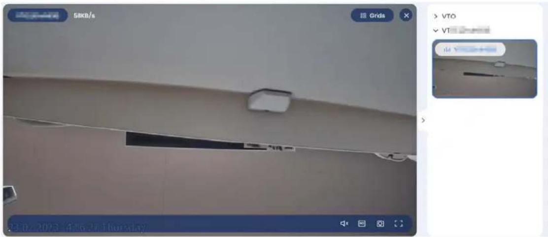
Table 5-1 Icons description
| Icons Functions | |
| Click to divide the view into 4 windows. | |
| Click to open the audio. The audio is closed by default. | |
| [ASS2] | Click to change the video streams. The main stream has a higher image quality but is not as smooth. The sub stream is smooth but has a lower image quality. |
 | Click to take a snapshot. |
 Click to maximize the view. Click to maximize the view. | |
Step 4 In the playback area, click the video file to play it.

The device will produce videos after being inserted a SD card or installed a hard disk, and the function of device image and video stream has been enabled.
5.3.7 Managing Network Transmission Devices
You can go to the home page of the network transmission device to view the device information, alarm messages and port status. Supports configuring port VLAN and link aggregation. You can also edit, delete, configure and move the network transmission devices.
5.3.7.1 Viewing Topology
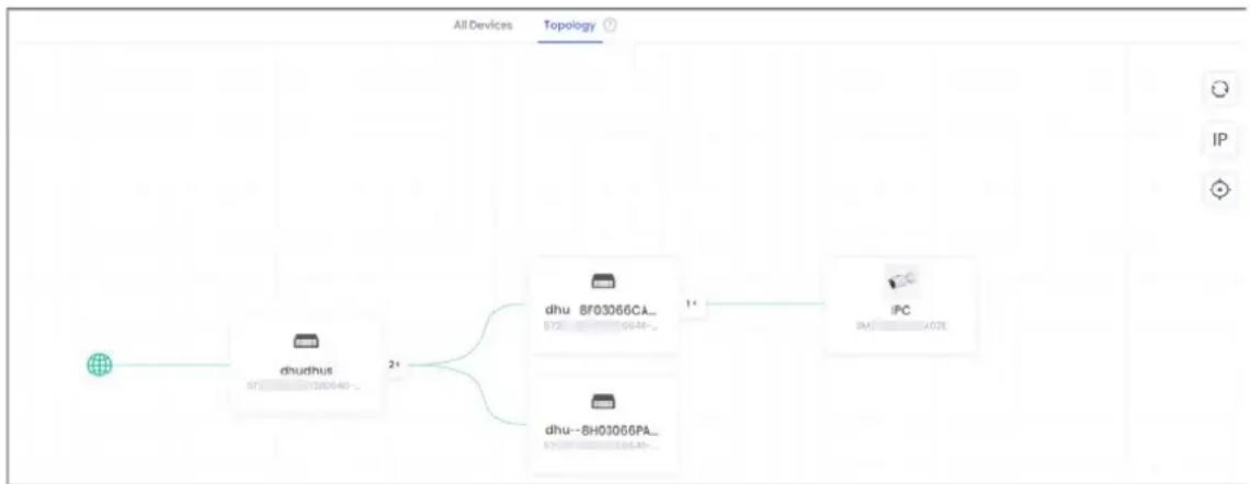
For the site that contains a network transmission device, you can view the topology of the devices in the site, and view the configured VLAN, link aggregation, loopback, error and live view of video channels.
Procedure
Step 1 Click Sites, and then select a site that contains a switch to go the site page.
Step 2 Click Topology on the top of the site page to view the topology of the devices in the site.

If there topology is not displayed properly, click next to Topology, and then solve the problem according to the suggestions.
Figure 5-5 Topology
flowchart
graph LR
    A["All Devices"] --> B["Topology"]
    B --> C["IPC"]
    A --> D["dhu_ BF03066CA_<br>572 09:46-"]
    A --> E["dhu--BH03066PA_<br>572 10:18-"]
    D --> F["IPC"]
    E --> F
- If there is an error occurs in the device, you can view and process the error through topology.
- The device with errors will be marked as 4. Click the device on the topology and
then the error information will be displayed on the right of the page.

The number in the mark represents how many errors in the devices.
- Click to process the error. For details, see "4.3.2 Processing the Error Tasks".
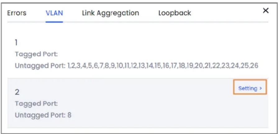
- View the VALN.
- Click a switch on the topology.
- Click VALN on the right of the page to view the information of configured VLAN.
- Hover over the VALN card, and then click Setting to go to the VALN configuration page. For details, see "5.3.7.5 Configuring Device VALN".
Figure 5-6 Viewing VLAN on the topology
• View the link aggregation.
- Click a switch on the topology.
- Click Link Aggregation on the right of the page to view the information of configured aggregation.
- View the loop.
- Click a switch on the topology.
- Click Loopback on the right of the page to view the information of loop.
- View the live video.
- Click a device that has a video channel on the topology, such as IPC or NVR.
- Click Video on the right of the page to view the live video.
For the operation of live video, see "5.3.6 Live View Page".
Related Operations
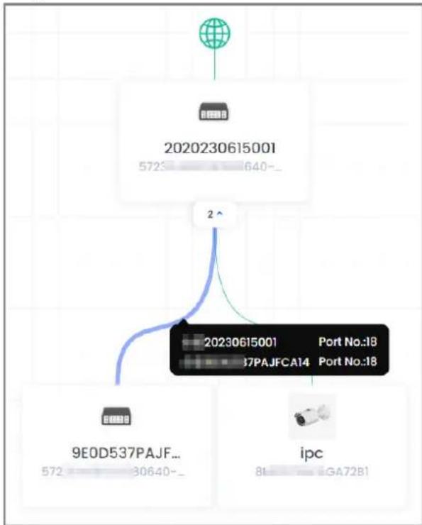
- Hover over the line on the topology. The information of device and port on the line will be displayed.
Figure 5-7 The information on the line
flowchart
graph TD
    A["2020230615001"] --> B["2"]
    B --> C["9E0D537PAJF..."]
    B --> D["ipc"]
    C --> E["Port No:18"]
    D --> F["Port No:18"]
- The number next to the device on the topology represents the devices connected to the switch. You can click the number to fold/unfold the devices.
- Click to refresh the topology.
- Click to display or hide the IP of the devices on topology.
- Click to adaptively display the topology.
5.3.7.2 Configuring Switches
Procedure
Step 1 Click Sites, and then select a site that contains a switch to go the site page.
Step 2 Select a switch and then click.
Figure 5-8 Switch configuration
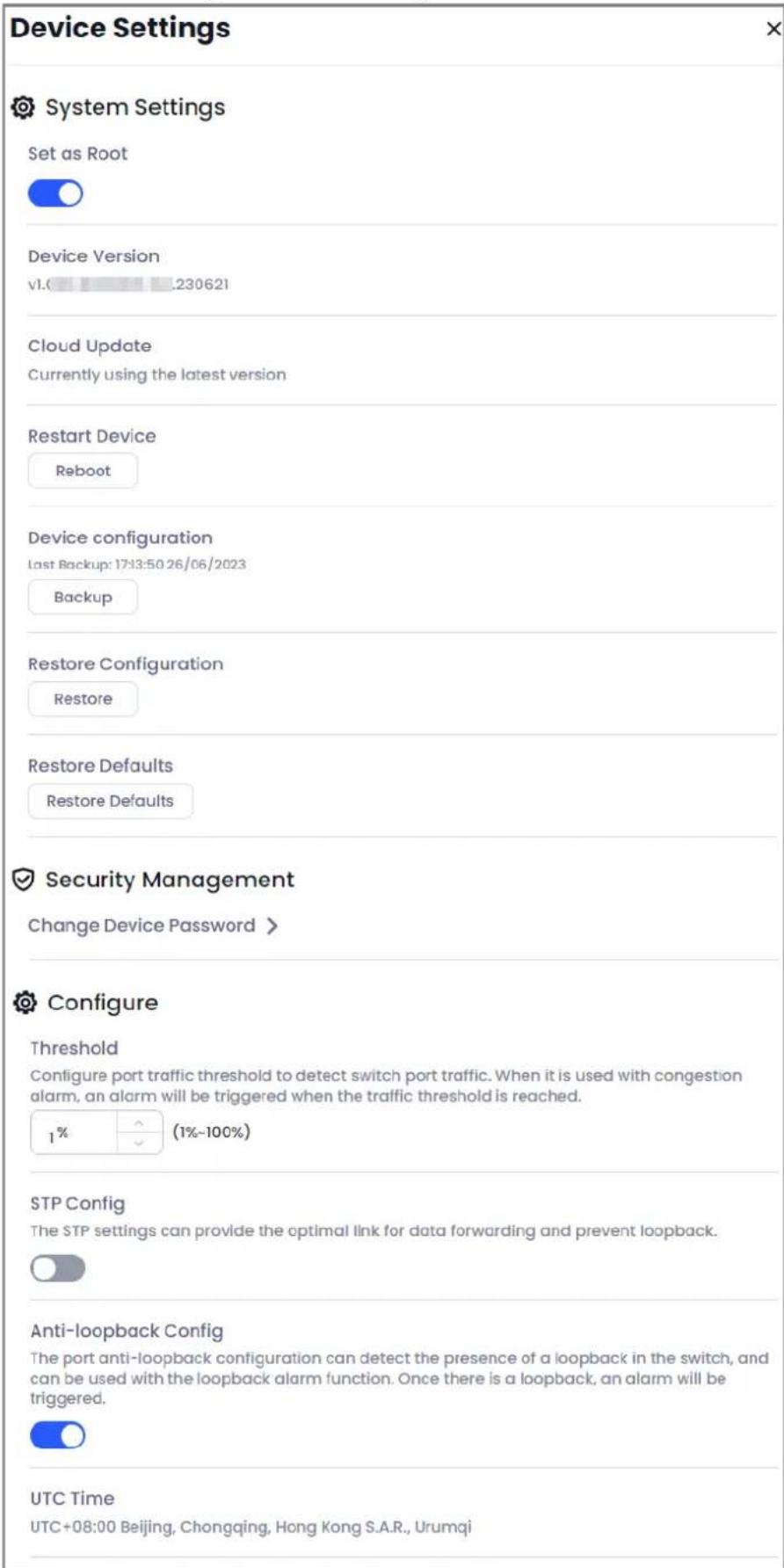
Table 5-2 Parameter description of switch
| Parameter Description | |
| Set as Root | Click to set the switch as the root. You can view the subordinate devices on the topology. |
| Device Version | Displays the current version of the device. |
| Cloud Update | When there is an available new version for upgrading, you can upgrade the device to the newest version. |
| Restart Device | Click Reboot to restart the switch. |
| Device Configuration | Displays the time of last backup. You can click Backup to back up the current configuration. |
| Restore configuration | Click Restore to restore the device configuration from the last backup. |
| Restore default | Click Restore Default to restore the device to its factory defaults. |
| Change device password | Click > to go to the change device password page. Enter the old and new password, and then confirm the new password. Click Complete. |
| Threshold | Click / or enter a value to set the alarm threshold for port congestion. An alarm is triggered when port congestion exceeds the set value. |
| STP Config | STP (Spanning Tree Protocol) is a kind of management protocol that provides optimal links for data forwarding and prevents the generation of loops.1. Click to enable the function.2. Configure the Work Mode. Select RSTP by default.3. Configure the Bridge Priority Config. Select 32768 by default. The switch with the lowest bridge priority in the topology will be elected as the root switch. • STP: The basic Spanning Tree Protocol.• RSTP (Rapid Spanning Tree Protocol): Based on STP, it has been improved to realize the rapid convergence of network topology. • STP: The basic Spanning Tree Protocol.• RSTP (Rapid Spanning Tree Protocol): Based on STP, it has been improved to realize the rapid convergence of network topology. |
| Anti-loopback Config | Click to enable the function. After it is enabled, an alarm will be triggered when the system detects a loop. |
| Perpetual PoE | Click to enable the function. After it is enabled, the system will ensure that the port can supply power to the front-end device without disruption, even if the switch is restarted. This parameter is only available for devices that support the perpetual PoE function. This parameter is only available for devices that support the perpetual PoE function. |
| UTC time Displays the UTC time that was configured on the device. | |

The STP function and anti-loopback function can be disabled at the same time, but cannot be enabled at the same time.
5.3.7.3 Viewing Alarm Messages
You can view the alarm messages of the switch, and search for the messages by type, port or time.
You can also configure the subscription message.
Procedure
Step 1 Click Sites, and then select a site that contains a switch to go the site page.
Step 2 Select a switch, and then click ☐ to go to the home page of the switch.
Step 3 Click View Alarm Messages.
You can view the information of the messages, including message type, port No., triggered time, IP address and MAC. You can select alarm message type, port or time on the top of the page to filter the alarm messages.
Step 4 Click Message Subscription to select the alarm message types that you want to receive.
You can select from IP Conflict, Loopback Alarm, Network Connection and Port Congested.

The configuration of subscription message types for the same account are valid for both web page and app.
5.3.7.4 Configuring Port
You can view the port status and configure the port settings on the home page of the switch.
Procedure
Step 1 Click Sites, and then select a site that contains a switch to go the site page.
Step 2 Select a switch, and then click ☐ to go to the home page of the switch.
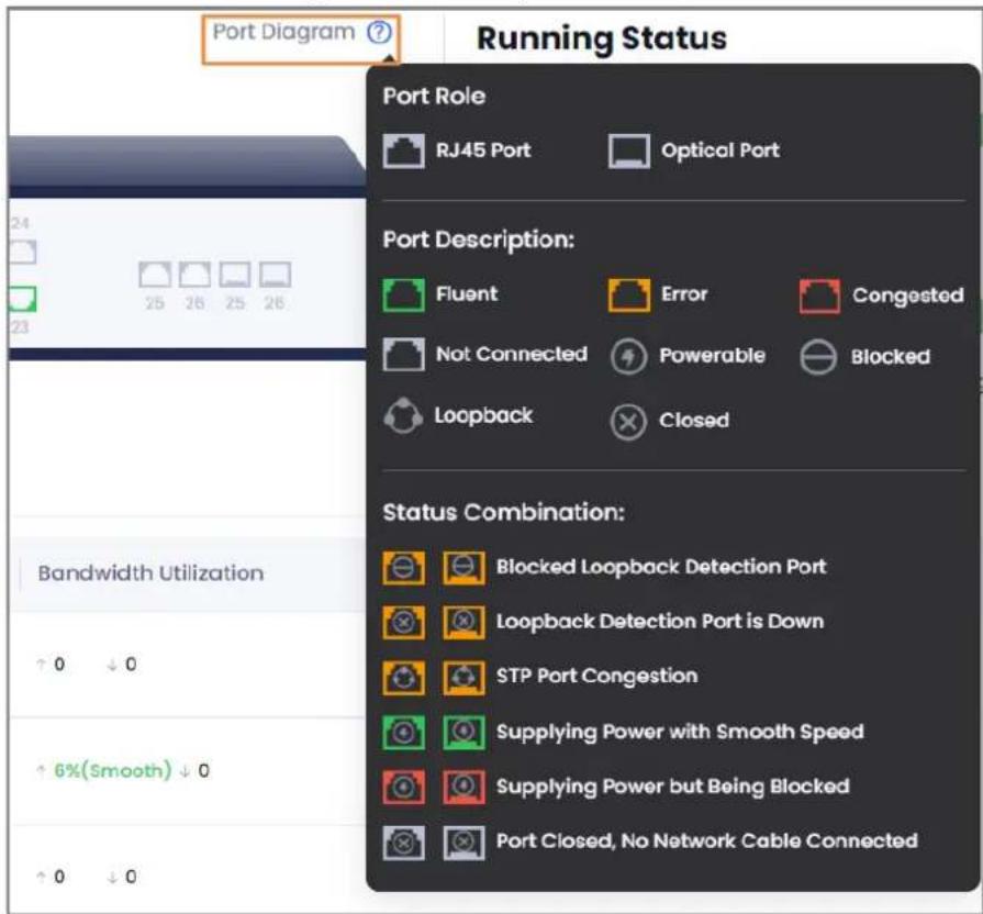
- View the status of the port, including port diagram, flow, speed rate, bandwidth utilization and speed/duplexing.

For the meaning of port diagrams, you can click next to Port Diagram on the top of the page to view the meaning.
Figure 5-9 Port diagram
• View the peer device.
Click to view the peer device of corresponding port, including Device Name, Device Type and Device IP.
- Configure the port.
Figure 5-10 Configure the port
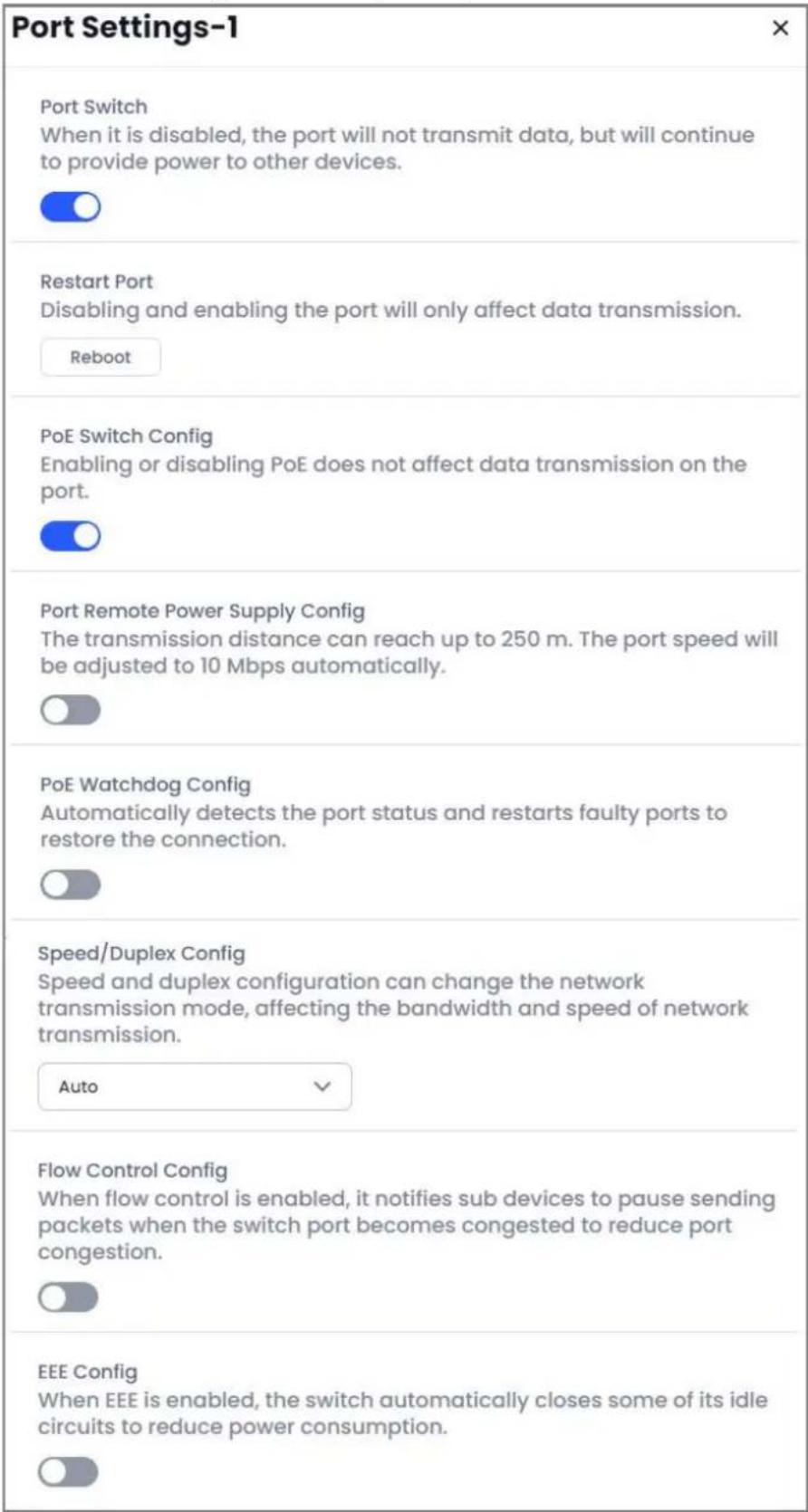
Table 5-3 Parameter description of port configuration
| Parameters Description | |
| Port Switch | Click / to enable or disable the port. |
| Restart Port | ClickRebootto restart the port. |
| PoE Switch Config | Click / to enable or disable the PoE. |
| Port Remote Power Supply Config | Click / to enable or disable the function. |
| PoE Watchdog Config | Click / to enable or disable the function. After enabled, the switch automatically checks the status of PD (Powered Device) end devices every 60 s, and automatically shuts down and restarts the PoE port if there is no data transfer, thereby achieving port monitoring and keeping PD end devices online. |
| Speed/Duplex Config | SelectAutoby default. The option is based on the ability of port.Full means full duplex.Half mean half duplex. |
| Flow Control Config | Click / to enable or disable the function. |
| EEE Config | Click / to enable or disable the function. |
5.3.7.5 Configuring Device VALN
You can add a VLAN ID so that you can add ports to the configured VLAN ID to configure a VLAN group. Supports viewing the information of VLAN groups, including tagged port and untagged port.
Background Information
VLAN (Virtual Local Area Network) is a logical set of devices and users that are not constrained by physical location and can be organized according to functions, departments, and applications, and communicate with each other as if they were in the same network segment. At the same time, they can be shared with other information systems that share physical network links without disturbance.
Procedure
Step 1 Click Sites, and then select a site that contains a switch to go the site page.
Step 2 Select a switch, and then click ☐ to go to the home page of the switch.
Step 3 Click Device VLAN. Displays the VLAN whose VLAN ID is 1 by default.

You cannot delete the VLAN whose VALN ID is 1.
Step 4 Click Add VLAN to enter the VLAN ID, and then click OK.

- The range of VLAN ID is 2 to 4094.
- You can add a single VLAN, a range of VLANs or multiple sets of VLANs.
5.3.7.6 Configuring Port VLAN
You can add a port to the VLAN ID, and configure the port VLAN mode.
Procedure
Step 1 Click Sites, and then select a site that contains a switch to go the site page.
Step 2 Select a switch, and then click ☐ to go to the home page of the switch.
Step 3 Click Port VLAN and then configure the parameters.
Figure 5-11 Port VLAN
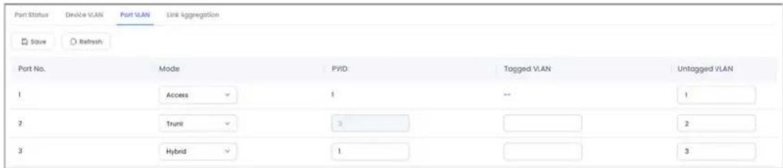
Table 5-4 Description of port VLAN
| Parameter Description | |
| Port | Displays all the ports of the switch. |
| Mode | Includes 3 kinds of modes: Access, Trunk and Hybrid.Access: Mainly be used for the ports to connect to devices, such as PC and IPC.In access mode, you can configure the Untagged VLAN, and only one VLAN can be added at a time.Trunk: Mainly be used for the ports to connect to switches.In trunk mode, you can configure Tagged VLAN and Untagged VLAN. You can add a single VLAN, a range of VLANs or multiple sets of VLANs for the tagged VLAN at a time. For example,Enter 2 to add the port to the VLAN whose VLAN ID is 2.Enter 2–5 to add the port to the VLANs whose VLAN IDs are from 2 to 5.Enter 2, 3–5, 8 to add the port to the multiple sets of VLANs whose VLAN IDs are 2, 3, 4, 5 and 8.Hybrid: Mainly be used for the ports to connect to switches, routers or end devices. You can configure the Tagged VLAN, Untagged VLAN and PVID. |
| PVID | Access mode: Set as 1 by default. After you configured the value of untagged VLAN, the PVID will keep same as the value of untagged VALN.Trunk mode: Set as 1 by default. After you configured the value of untagged VLAN, the PVID will be filled in automatically.Hybrid mode: Set as 1 by default. You can configure it and only one VLAN can be added at a time. |
| Tagged VLAN | Access mode: You cannot configure it. Keep empty by default.Trunk and hybrid mode: You can add a single VLAN, a range of VLANs or multiple sets of VLANs for the tagged VLAN at a time. |
| Untagged VLAN | Only one VLAN can be added at a time. |
5.3.7.7 Configuring Link Aggregation
Link aggregation allows traffic to be spread across member ports in an aggregation group to increase bandwidth. Each member port of the same aggregation group dynamically backs up to
each other, improving the reliability of the link.
5.3.7.7.1 Configuring Load Balancing
Procedure
Step 1 Click Sites, and then select a site that contains a switch to go the site page.
Step 2 Select a switch, and then click ☐ to go to the home page of the switch.
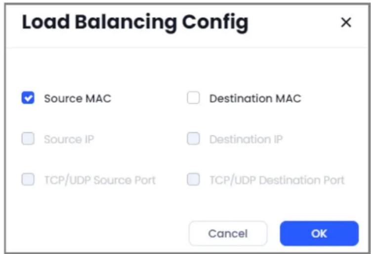
Step 3 Select Link Aggregation > Load Balancing Config, and then select load balancing mode. Includes the following options:
- Source MAC means link aggregation calculation based on the source MAC address of packet.
- Destination MAC means link aggregation calculation based on the destination MAC address of packet.
- Source IP means link aggregation calculation based on source IPv4.
- Destination IP means link aggregation calculation based on destination IPv4.
- TCP/UDP Source Port means link aggregation calculation based on TCP/UDP source port.
- TCP/UDP Destination Port means link aggregation calculation based on TCP/UDP destination port.
Figure 5-12 Load balancing configuration
Step 4 Click OK
5.3.7.7.2 Adding Link Aggregation
You can add link aggregations to realize the load balancing.
Procedure
Step 1 Click Sites, and then select a site that contains a switch to go the site page.
Step 2 Select a switch, and then click ☐ to go to the home page of the switch.
Step 3 Select Link Aggregation > Add Link Aggregation, and then configure the parameters.
Figure 5-13 Add link aggregation
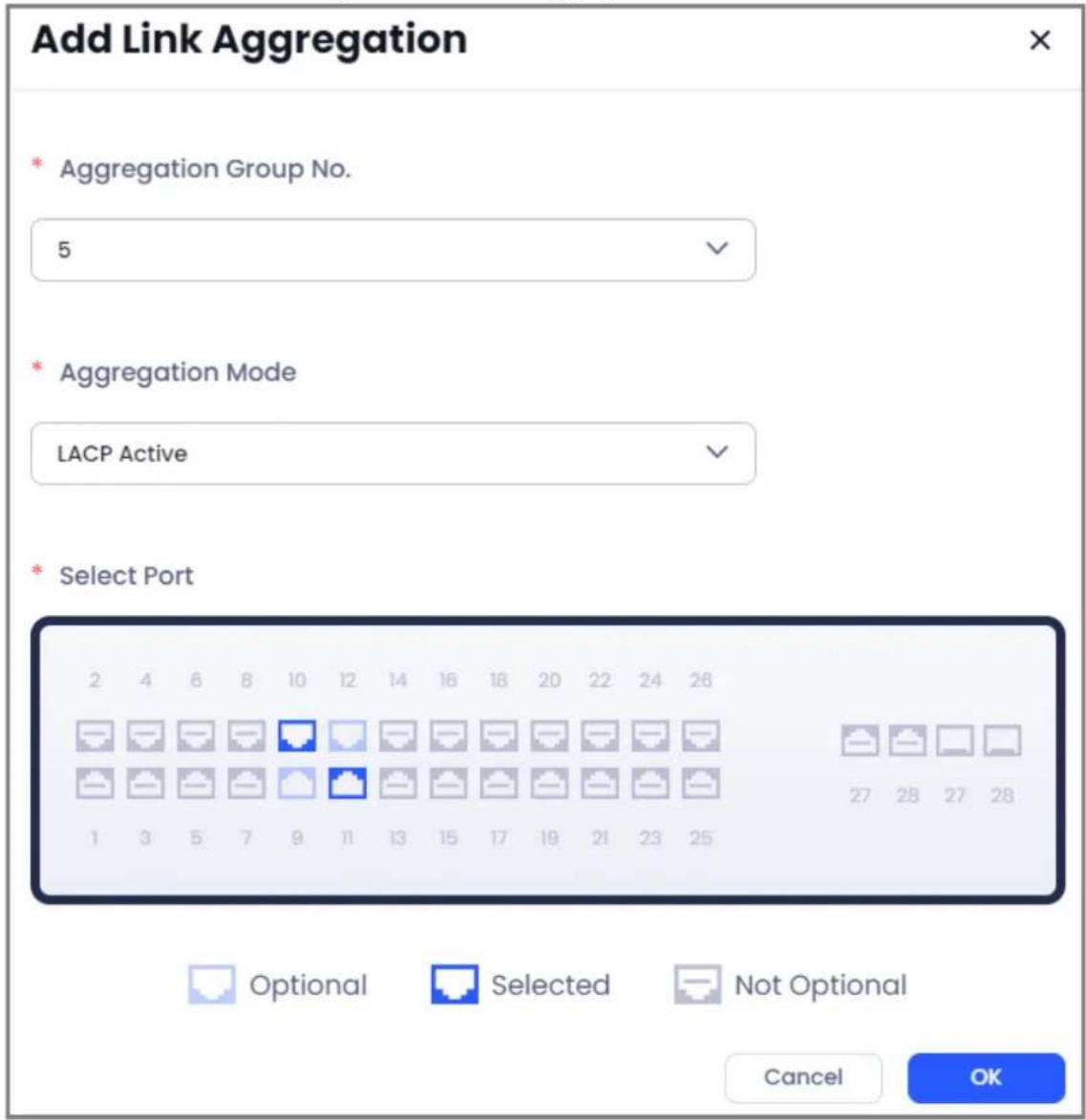
Table 5-5 Parameters description of link aggregation
| Parameter Description | |
| Aggregation Group No. | Select the number of link aggregation.The max group numbers that you can select are based on the abilities of devices. |
| Aggregation Mode | Select the aggregation mode. SelectLACP Activeby default.Static:Static link aggregation. It is simple and reliable, but not adaptable to dynamic changes in the network, usually used in the situation that the peer device does not support the LACP protocol.LACP Active:In active mode, the LACP protocol is enabled unconditionally at the local end regardless of whether the peer device supports the LACP protocol. In this mode, the port is in an active negotiation state.LACP Passive:In passive mode, the LACP protocol will be enabled only if it is detected that the peer device supports the LACP protocol. In this mode, the port is in a passive negotiation state. |
| Select Port | Click the icon of the port to add the port into the aggregation.Click the selected port again to cancel the selection.After you selected a port, the system will filter those ports that are conflict with the selected port automatically, and you cannot select them.The max ports that you can add into a aggregation are based on the abilities of devices. |
Step 4 Tap OK.
5.3.8 Managing Alarm Hubs
You can go to the device home page to view the alarm hub information, alarm message, lending period, and select the arm mode and more. You can also manage the peripherals and bind the Converter account.
Procedure
Step 1 Click Sites and then select the site that contains an alarm hub.
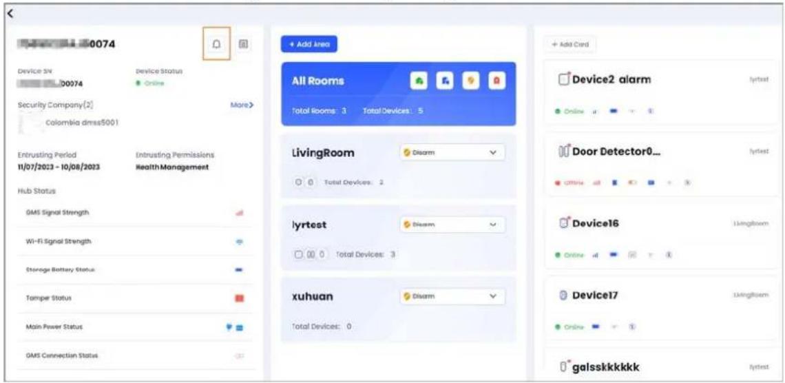
Step 2 Click ☐ to go to the device home page, and then view the hub information, hub status, area information, and accessory details.
Figure 5-14 Alarm hub home page
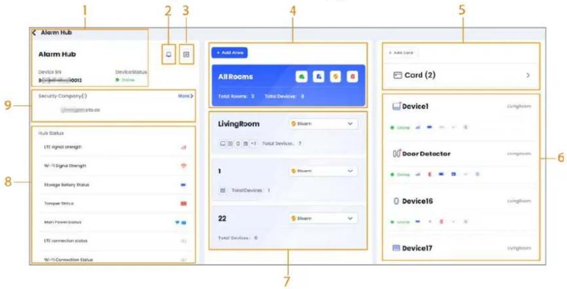
Table 5-6 Alarm hub home page introduction
| No. Introduction | |
| 1 Displays the alarm | hub information, including name, device SN and status. |
| 2 Click the icon to view the alarms and error messages. | |
| 3 | Click the icon to view the device logs and app logs. You can send the logs to current user email. |
| 4 | Displays the rooms information and devices number.Click to arm all the areas as Home.Click to arm all the areas as Away.Click to disarm all the areas.Click Add Area to add new areas. |
| 5 | Mange the cards of the users.Click > to view the cards that were already added.Click Add Card, and then follow the pop-up window to add a new card. |
| 6 | Accessory information.Click the area card to view the corresponding accessory information in this area.Click the accessory card to view the detailed information.Click to edit the accessory information. You can modify the name and assign an area for the accessory.Only supports to edit the online accessories. |
| 7 | Displays the added areas and device number in the area.You can select the arm status, includingHome, Awayand Disarm.Click to edit the area name.Click to delete the current area. Only the area that has no devices can be deleted. Only the area that has no devices can be deleted. |
| 8 | Displays the alarm hub status, including signal strength, battery status, network connection status, program version and more. |
| 9 | Displays the bound security company. You can bind multiple security companies. ClickMoreto view more security companies. |
Related Operations
- On the device list page, click ☑ to lend the device to the site customer. Click 🔒 to cancel lending the device.
- On the device list page, click , or click , and then select Settings to go to the device settings page. You can upgrade the device through cloud, restart the device, backup or restore the configuration of the device, restore the device to default configuration and change the password.
5.3.8.1 Configuring Alarm Hub
You can configure the alarm hub, including device settings, user management, arming/disarming settings, alarm settings and network settings.
5.3.8.1.1 Device Settings
Procedure
Step 1 Click Sites and then select the site that contains an alarm hub.
Step 2 Select an alarm hub, and then click 🔒 to go to the settings page.
Step 3 Click Device Settings to configure the parameters.
Table 5-7 Parameters description of device settings
| Parameter Description | |
| LED Indicator | Disabled by default. Click to enable the function.When the function is disabled, the LED indicator will stop from lighting up for alarms, errors and arming/disarming statuses. |
| Reduced Sensitivity Mode | Click to enable the mode.When the mode is enabled, the alarm hub will reduce reception sensitivity and simulate changes in the installation environment. It is for testing purposes only.The alarm hub will automatically exit the reduced sensitivity mode after 30 minutes. |
| Cloud Service Connection Interval | Set the server-hub ping interval with the range from 150 to 900 seconds (150 seconds by default). If the D-cloud detects that the hub's offline duration exceeds 150 seconds, it will report the hub status to the user through app. |
| Arming Indicator | Tap to send a test command to the corresponding detectors. The indicator light will always be on after the detector is triggered until it exits the test mode.The detector will automatically exit the test mode after 3 minutes. |
| Keep Heartbeat Alive | Configure the hub-detector ping interval. The settings determine how frequently the hub communicates with the accessories and how quickly the loss of connection is detected.Detector Ping Interval: The frequency of connected accessories operated by the hub is configured in the range of 12 seconds to 300 seconds (60 seconds by default). The shorter the detector ping interval, the shorter the life span of the battery.Range for Offline Packet Loss Reporting of Alarm Hub: A counter of undelivered packets is configured in the range of 3 to 60 (15 packets by default). The smaller the number, the more frequently the offline status of accessories is detected and reported.If the hub constantly loses connection with the accessories and cannot detect their defined heartbeats, it will report their offline status to the system. |
| System Integrity Check | Disabled by default. When enabled, the hub checks the status of all detectors before arming, such as battery charge level, tamper incidents, and connectivity.When the function is disabled, even if errors are detected, arm the area without prompts.When the function is enabled, arm the area successfully when there is no error detected.When there are errors detected, a pop-up window will display the information of errors, and you can select to force arming or cancel the arming. If you are using a keyfob, you will receive the reason for the failure of the arming, and you can arm again within 30 seconds.When the function is enabled, the functions of the main power failure detection, alarm hub tamper detection, connected to cloud platform detection, wired network and Wi-Fi errors detection, cellular network errors detection and RF jamming detection must be enabled.For details, see "5.3.8.1.4 Alarm Settings".If the detecting functions of these errors are not enabled, the system will not prompt these errors and directly be armed. |
| Device Password | Click Change Device Password to change the password of the alarm hub. |
| Restart Device | Click Reboot to restart the device. |
| Cloud Update | You can perform cloud upgrade when the system detects an upgradeable version of the program. |

You can click User Manual next to the device name on the top of the page to view more information on device settings.
5.3.8.1.2 User Management
You can create keypad users and add cards for the users. The user can arm/disarm the area by swiping the bound card or entering the password. You can also add phone numbers for the users. Users can receive SMS push for alarms, errors and operation notification.
Procedure
Step 1 Click Sites and then select the site that contains an alarm hub.
Step 2 Select an alarm hub, and then click 🔒 to go to the settings page.
Step 3 Click User Management
- Add users.
-
Click Add.
-
Configure the information on the user and assign permissions and areas for the user.
Figure 5-15 Add a user of keyfob
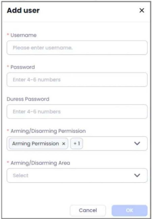
◇ Duress Password: Set the duress password.
- Arming/Disarming Permission: Select the arming or disarming permission for the user.
- Arming/Disarming Area: Assign the area for the user so that the user can arm or disarm the area.
3. Click OK.
- Manage the phone number.
- Click Add.
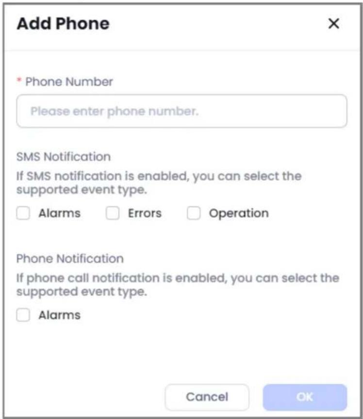
- Enter the phone number, and then select the types of SMS notification and phone call notification.

For the phone call notification, only alarms is available.
Figure 5-16 Add phone number
3. Click OK.
Related Operations
- Click + on the user management area to add a card for the user.
- Click 📞 / 🌐 on the phone No. management area to test the SMS or phone call.
- Click to edit the information on users or phone number.
- Click ☐ to delete a user or phone number.
5.3.8.1.3 Arming/Disarming Settings
You can configure the buttons of global arming/disarming, add scheduled arming/disarming and set the ringtone of arming/disarming.
Procedure
Step 1 Click Sites and then select the site that contains an alarm hub.
Step 2 Select an alarm hub, and then click 🔒 to go to the settings page.
Step 3 Click Arming/Disarming Settings
- Global Arming/Disarming: Click 🐘/ 🐘 to enable or disable the arming/disarming button on the home page of the alarm hub.
- Scheduled Arming/Disarming: Up to 8 schedules can be added. You can enable or disable the added schedules.
1. Click Add.
- Configure the parameters of scheduled arming/disarming.
Figure 5-17 Add scheduled arming/disarming
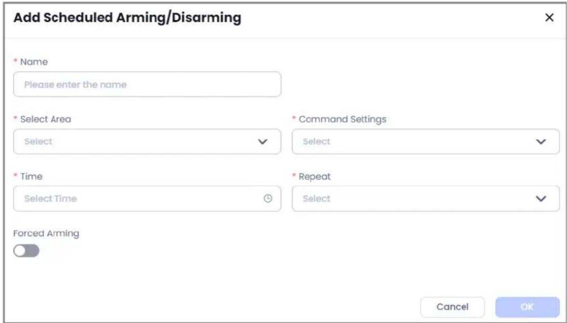
Table 5-8 Parameters description of scheduled arming/disarming
| Parameter Description | |
| Select Area | Select the area that you want to add a scheduled arming/disarming. For the area configuration, see "5.3.8 Managing Alarm Hubs". |
| Command Settings | Select the command that the schedule will carry out. You can select from Disarm, Away or Home. |
| Time Select the time for the schedule to carry out the configured command. | |
| Repeat | Select the repeat time for the scheduled arming/disarming. |
| Forced Arming | Tap to enable the function as needed.After the function is enabled, the command for the scheduled arming/disarming is invalid. In the system integrity check scenario, even if the system detects an error, the scheduled arming can be carried out successfully. |
3. Click OK
- Ringtone settings: Click 📄/ 🔒 to enable or disable the buzzer. After enabled, there will be sound prompt for arming or disarming.
5.3.8.1.4 Alarm Settings
Configure the notification and detection types. Supports setting the alarm center so that the alarm hub can be registered to DSS Pro platform or Converter.
Procedure
Step 1 Click Sites and then select the site that contains an alarm hub.
Step 2 Select an alarm hub, and then click 🔒 to go to the settings page.
Step 3 Click Alarm Settings.
- Notifications and Health Check: Click / to enable or disable the functions of
pushing the notification and detecting the errors. After being disabled, you cannot receive the corresponding notification or errors.

If you enable the functions of health check, when the system detects an error, you cannot arm the area successfully when the system integrity function is enabled. There will be a pop-up window and notification to inform you about the error.
When the function of wired network and Wi-Fi network errors detection is enabled, it will report an error when both wired network and Wi-Fi network are failed.
When the function of wired network and Wi-Fi network errors detection is enabled, if the function of cellular network is not enabled, the system will not detect the Wi-Fi network status.
- Link Siren for Tamper and Trigger Siren When Disarmed: Click / to enable or disable the function.
- Central Monitoring Station (CMS): Click 🔍 to enable the CMS function.
You can configure the IP/domain and port of DSS Pro or Converter, and enter the ID of device. Click Save. After the function is enabled, you can register the alarm hub to the DSS Pro or Converter.
- Alarm Center:
- Click Settings, and then configure the parameters.
Figure 5-18 Alarm center settings
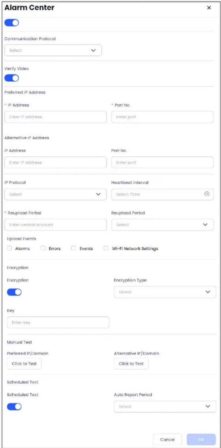
Table 5-9 Parameters description of alarm center
| Parameters Introduction | |
| Alarm Center | Click 📄/ 🔒 to enable or disable the alarm center. |
| Communication Protocol | Select the protocol type. Select SIA-DC09 by default. Softgard and Private are the private protocols. |
| Verify Video | Click /to enable or disable the function.After enabled, the alarm hub will send the URL of images and videos taken by PIRCam to the alarm center. |
| Preferred IP Address | Enter the IP and port No. of preferred ARC. |
| Alternative IP Address | Enter the IP and port No. of alternative ARC. |
| IP protocol | Select TCP by default. When you create an account on ARC, you must select the same protocol as here. |
| Heartbeat Interval | Configure the heartbeat interval between the alarm hub and ARC. If the interval exceeds the value, then the system judges that the alarm hub is offline and select alternate ARC to report alarms and notifications. |
| Central Account Enter the account of ARC. | |
| Reupload Period | Configure the reupload period when failed to send the messages. The messages that failed to be sent will not be reuploaded beyond this period. |
| Upload Events | Select the events that you want to report to the ARC.Alarms: Alarm messages.Errors: The errors messages, including main power failure, low battery, tamper, device offline and more.Events: Includes the notifications on enabling/disabling the peripherals, adding/deleting peripherals and adding/deleting users.Arming/Disarming: Arming and disarming notifications. |
| Encryption | Click /to enable or disable the function. After enabled, you must select the encryption type. It is recommended to select AES128. When you create an account on ARC, you must select the same encryption type as here. |
| Manual Test | Select Preferred IP/Domain or Alternative IP/Domain, and then click Click to Test to test whether the communication between alarm hub and ARC is normal. The test result will come back within 30 seconds. |
| Scheduled Test | Click /to enable or disable the function.After enabled, you can select the Auto Report Period. A periodic test report will be sent to the ARC every set period of time. |
- Click OK.
5.3.8.1.5 Network Settings
Procedure
Step 1 Click Sites and then select the site that contains an alarm hub.
Step 2 Select an alarm hub, and then click 🔒 to go to the settings page.
Step 3 Click Network Settings.
- Wired Network Configuration.
-
Configure the wired network, including IP, subnet mask, gateway, DNS and MAC.
-
Click Save.

When a DHCP server exists on the network, you can click to enable the DHCP, and then the alarm hub can automatically obtain a dynamic IP address.
• Wi-Fi network configuration.
-
Click to enable the Wi-Fi network.
-
Click Change Wi-Fi to select the Wi-Fi network. Enter the password of the Wi-Fi network and then click Connect.
-
Click OK.

Click Refresh to refresh the Wi-Fi network list.
- Cellular network configuration.
- Configure the parameters of the cellular network.
Table 5-10 Parameters description of cellular network
| Parameters Description | |
| Cellular Network | Click to enable the cellular network. |
| Priority Click to set the cellular as the priority network. | |
| SIM1/SIM2 | Support dual SIM cards.The alarm hub can use the cellular traffic of the SIM card to send messages. |
| User Name | Enter the user name and password of the SIM card. |
| Password | |
| APN | The Access Point Name (APN) is the name that the device reads to establish a gateway connection between the carrier's cellular network and the public Internet. |
| Authentication Mode | Enter the authentication mode. |
| Dial No. Enter the dial No. | |
| PIN Code Enter the PIN code of the SIM card. | |
| Mobile Data Usage | Displays the used data of cellular traffic. |
| Reset Statistics | Click to reset the used data of cellular traffic. |
- Click Save.
5.3.8.2 Viewing Messages
You can view the alarm messages and arming/disarming messages on the home page of alarm hub.
Procedure
Step 1 Click Sites and then select the site that contains an alarm hub.
Step 2 Select an alarm hub, and then click 🔒 to go to the settings page.
Step 3 Click ☐ to view the alarm messages and arming/disarming messages.
Figure 5-19 Viewing messages

Unread messages are marked with

Related Operations
Click the message to view the details, including the source, content, time and types of the messages.
5.3.8.3 Managing Accessories
You can add accessories to the alarm hub. You can view the status and configure the parameters of the accessories in alarm hub page.
- Click the accessory card to view accessory status.
- Takes outdoor siren as an example. You can view the status including temporarily unavailable, temperature, signal strength, external power status, tamper status, online status, alarm volume, alarm duration, sound prompt for entering or exiting arming and disarming, beep volume, repeat status and program version.

The status that you can view is based on the actual accessories.
- Hover the mouse over the accessory card, and then click 📋 to test the accessory. Takes PIRCam as an example. You can select Snapshot Test, Signal Strength Test, Zone Test and RF-HD test.
Table 5-11 Test description
| Test items Description | |
| Snapshot test | Test the PIR camera snapshot. You can adjust the installation position according to the snapshot image. |
| Signal strength test | Test the signal strength of the current position. Select the position with the best signal strength to install the PIR camera. Click Start Check to test the signal strength. The test will end after 180 seconds. You can also click Stop Test to stop the test immediately. |
| Detector test | Test the signal strength in the zone. Click to test the signal strength.The test will be ended after 180 seconds. You can also clickStop Testto stop the test immediately. |
| RF-HD Test | Test RF-HD signal strength and check whether it is connected. Click to test the signal strength. The test will be ended after 120 seconds. You can also clickStop Testto stop the test immediately. |
- Click 🔔 to edit the accessory. You can change the name, assign areas and delete the accessory.
- Click to go to the settings page of the accessory.

◇ You cannot configure the accessory that is offline.
◇ You cannot configure the accessory that is in arming status.
5.3.9 Alarm Receiving Center Service
You can apply security service for alarm hub. Bind the devices to the security companies in the region. The security companies must register the Converter account first. The alarm messages will be sent to the bound Converter account and the security companies can process the alarms.

You can only apply security service for the alarm hubs whose status is To be Delivered, or the entrusted and lent alarm hubs that have configuration permissions.
5.3.9.1 Creating Converter Accounts
The security companies must register a Converter account on company official website. DoLynk Care users can bind the alarm hubs to the Converter account.
Procedure
Step 1 Enter the URL of company official website in the browser and then press enter.
Step 2 On the home page, find the registration portal of Converter and then click Register.
Step 3 Configure the account information, including email, company name, country/area, address, logo, username, language of replying email, business coverage area and password.
Step 4 Enter the verification code and click Agreement and Privacy Policy. I have read and agree to Converter Registration
Step 5 Click Sign up.
Figure 5-20 Creating Converter account
Welcome! Let's Create Your Converter Account.
someone@example.com
* Company Name
Please enter company name.
Country/Region
Please select the country and area.
* Company Address
Please enter company address.
* Business Coverage Area
Please select the business coverage area.
*Username
Please enter username
*Logo

* Email Language
English
* Password
Please enter password.
Verification Code
Please enter the verification code
Send
☐ I have read and agree to Converter Registration Agreement and Privacy Policy
sign up

- After registration, the account needs to be reviewed by the main and sub country account of DoLynk Dashboard.
- After login, if the trial software is not the latest version, please update.
5.3.9.2 Applying for Security Service
You can bind the alarm hub to Converter accounts. After binding, the alarms messages, notifications, error messages and events will be sent to Converter accounts.

If the bound Converter account is offline or logged out, the automatic network replenishment of the messages is 30 days.
Procedure
Step 1 Click Sites and select the site that contains alarm hub.
Step 2 Click More on the site list page, and then select Apply for Security Service.
Figure 5-21 Applying for security service
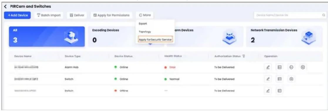
Step 3 Displays the devices that can be bound to the Converter account. Select the devices.
Step 4 Click Next to enter in to the binding page. The system displays all the security companies which are in the same city as the current DoLynk Care account, including the company name, email and logo.

- The same city indicates that the city that filled during registration of DoLynk Care account is within the Business Coverage Area that filled during the registration of Converter account.
- The Converter accounts whose available device access channels are less than the number of devices to be bound will not be displayed.
- If the country does not have available security companies, you can manually enter the email of the security company.
Related Operations
- After the binding application is sent, the Converter account must review and approve the application.
- For the device to be delivered, if the device has been bound to a Converter account, the binding relationship will transmit to DMSS when the device is delivered.
- If you want to bind the devices whose status are Entrusting or Lending to the Converter
accounts, you must apply for permissions from the DMSS first.
- After binding successfully, you can view the Converter information on the alarm hub home page.
5.3.9.3 Disabling the Converter Account
DoLynk Care cannot disable the binding relationship with Converter account. You must disable the relationship on Converter. After disabled, DoLynk Care will not send the messages to the Converter account.

If you delete the device, the binding relationship between the device and Converter account will be deleted, and the messages of the device will not be sent to Converter account any more.
6 Device Maintenance
6.1 Health Center
For details, see "4.5 Error Overview".
6.2 Health Diagnosis
You can diagnose the health status of the devices.
Prerequisites
Devices have been added to the sites, and the authorization status are to be delivered, entrusted and lent.
- If there are no sites, select Sites > Add Site. For details, see the adding site operation in "4.4 Device Overview".
- If there have been sites but no devices, select Add Device. For details, see the adding device operation in "4.4 Device Overview".
- If there have been sites and devices, you can check the device status and view the results.
Procedure
Step 1 Select Health Center > Health Diagnosis, and then enter the Health Diagnosis page.
The left side displays the site card with information including site name, device number, number of devices with errors, and the last check time.
The right side displays the diagnosis information. Before the checking, it displays site name, customer name, Email, address, numbers of devices to be checked, errors and devices with errors.
Step 2 Click Start Check, and then displays the results.

Some devices cannot be checked, including network transmission devices, devices that do not support check, and entrusted devices without permissions granted by the customer.
Step 3 Click Complete.
Figure 6-1 Health diagnosis
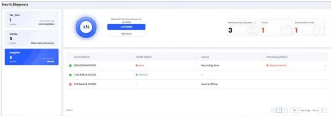
Step 4 (Optional) Fix the devices with errors. For details, see. After fixing the errors, click Recheck to check the health status.
6.3 Health Reports
You can view the errors that occurred to all devices under the site over a period of time.
Procedure
Step 1 Select Health Center > Health Reports, and then enter the Health Reports page.
Step 2 Select site and time, and then view the health reports.
Figure 6-2 Health Reports
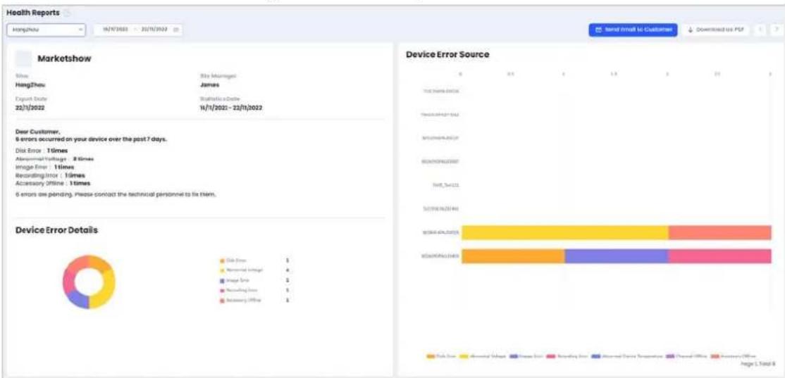
Related Operations
- Click Send Email to Customer, and then send the health report to the customer.
- Click Download as PDF, and then save the health report to local storage in PDF format.
7 Customer Management
You can manage your self-employed customers. View the detail information of the customers and their devices.
7.1 Viewing Customer List
View the self-employed customers of the current DoLynk Care account.
Procedure
Step 1 Click Customers.
Step 2 View the information of the customers and their devices, including authorization status and numbers.
Related Operations
- Click to view the complete email address.
- Hover the mouse over the customer card, and then click o to modify the customer's information. You can modify the customer's name and profile picture.
- (Optional) Hover the mouse over the customer card, and then click to delete the customer.

Only supports to delete the customer who has no site and no devices.
- On the upper-right corner of the customer list page, enter the name of the customer to search quickly.
7.2 Viewing the Device Information
Procedure
Step 1 Click a customer in the customer management page and enter the device list page.
Step 2 You can view the detailed information of the devices, including device name, types, sites, authorization status.
Related Operations
- You can filter site and authorization status to view the results.
- Click site name or device name to go to the site management page.
- Click 📷 to view more information of the device, including SN number, delivering time or lending period.
8 Company Management
8.1 Viewing Company Information
You can view and manage the company information.
Procedure
Step 1 Click Company, and then enter the Company page.
Step 2 View the company information, including Distributor Name, Inviter's Email, Invitation Code, Company Email, Tax Number, and Company Address.
Related Operations
- Change inviter: Click, enter Inviter's Email, and then Click Search. The Invitation Code will be filled automatically.
Figure 8-1 Change inviter
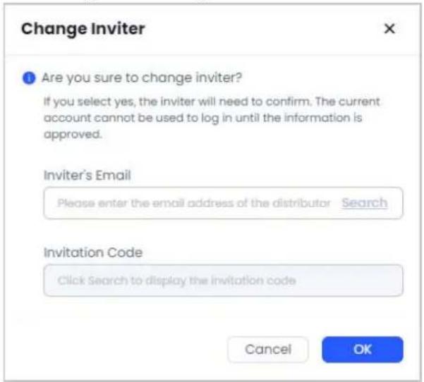
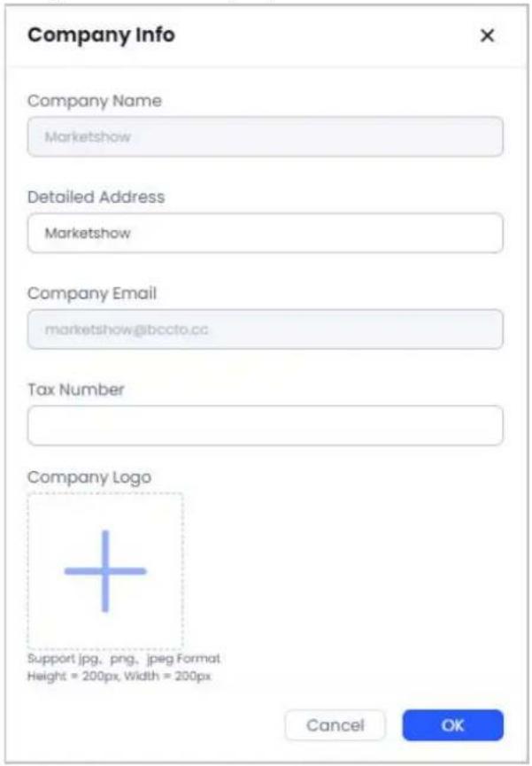
- Edit company information: Click, change Logo.
Detailed Address, Tax Number and Company
Figure 8-2 Edit company information
- Enable Co-Branding: Click to enable it, and the end user can see the logo, address and email of the installer or service provider.
- Scan the entrusting QR code, you can entrust devices with DMSS app.
8.2 Managing Operators
You can add operators and assign a site to the operator.
Procedure
Step 1 Click Company.
Step 2 Operator information is displayed in cards, and you can view the profile, name, email and managed site number.
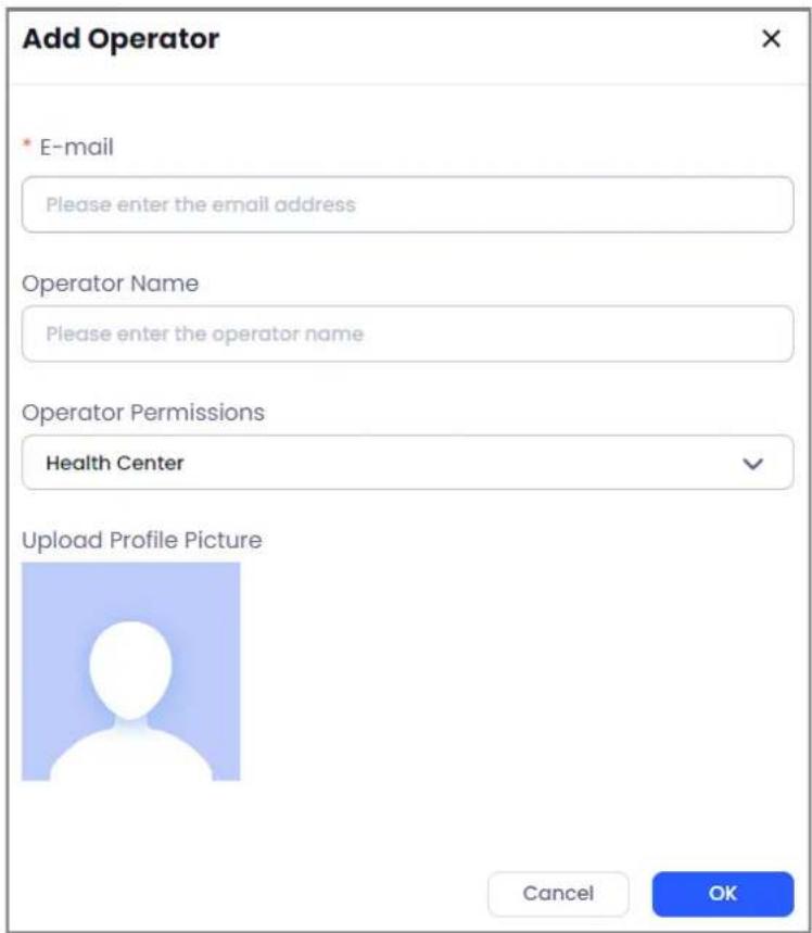
Step 3 Click Add Operator, configure the Operator Name and E-mail, and then select Operator Permissions.

- If the number of operator account exceeds the limit of the service package, you cannot add a new account and a new service package needs to be purchased.
- If the operator account added has already registered a personal account, you can invite it to become a company operator account, and the personal account needs to review the invitation.
After the invitation is accepted, the devices and sites under this personal account will be transferred to the default site of the company account, but the previous error data and site data will be cleared.
Figure 8-3 Adding an operator
- Edit operator account: Hover over the operator card, and then click 🔒 to edit Operator Name, Operator Permissions and profile picture.

Administrator account cannot be edited.
- Delete operator account: Hover over the operator card, and then click.

You can only delete the operator account that has no site under the account.
Step 4 (Optional) Click an operator to display all the sites under the operator account, including Site Name, Customer Name, Address, Devices, Devices with errors.
- Operate in batch. Select one or several sites:
◇ Click Assign to assign the site to other operators.
- Click Remove to remove all the sites under the current operator account.
◇ Click Delivery to deliver the sites to other operator account.
- Operate one by one. Select a site:
◇ Click ⊖ in the operation area to remove the site from the operator account.
◇ Click ☑ in the operation area to deliver the sites to another operator.
9 Service Management
9.1 Service Market
Select Services > Services to view the service package benefits and types.
Service Packages
Service packages include Mini Package, Basic Package and Premium Package.
- Mini package: Supports 5 operator accounts and 256 devices.
- Basic package: Supports 10 operator accounts and 512 devices.
- Premium package: Supports 18 operator accounts and 1024 devices.
Rules for Service Package
- If you are using the mini package, when purchasing basic package or premium package, the later two take effect immediately. Mini package displays Suspended, and the basic package or premium package displays In Service. After the package expires, it will turn to mini package.
- If you are using the basic package, when purchasing premium package, the premium package takes effect immediately. Basic package displays Suspended. After the package expires, it will turn to mini package. Some functions can be limited accordingly.
- When purchasing multiple service packages, they take effect according to the priority.
9.2 My Service
9.2.1 Package Information
You can view the information on the current package.
Prerequisites
You have purchased the service package, and is bound with operators and sites.
Procedure
Step 1 Select Services > My Service to view the currently-used service package.
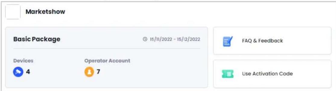
Step 2 View the company name, company profile, the current package period, device number and operator account number.
Figure 9-1 Package information
Related Operations
- Click FAQ & Feedback to view the frequently ask questions and solutions, and feedback method.

If you have additional questions, please contact: dolynksecurity@dolynk.com.
- Click Use Activation Code, enter Activation Code to redeem the service package.

You need to use credits to generate activation code in Partner app to redeem for different packages.
9.2.2 Order Information
You can view the information on the orders, including purchased orders and redemption orders.
Procedure
Step 1 Select Services > My Service, you can view the purchased orders in the Purchase Orders section.
Step 2 Select the service type and order status, you can filter to view the purchased orders.

- Service type includes Mini package, Basic package and Premium Package; Order status includes To be Paid and Paid.
- Order information includes Order No., Services, Content, Validity Period, Order Time, Order Status and Amount.
Figure 9-2 Purchased order

Related Operations
- Click ☐ to pay the unpaid order.
- Click ☐ to delete the unpaid order.
- Click Request Invoice to request receipts for orders that have been paid.

You need to contact after-sales to request invoice.
Appendix 1 Accessory Settings

The parameters that you can configure will be different based on the abilities of the accessories.
Appendix 1.1 Outdoor Siren
You can click the User Manual next to the device name to view more information on accessory settings.
- Supports enabling or disabling the over-temperature alarm. After being enabled, you can set the threshold for triggering an alarm.
● Supports setting the siren sound, and select the sound types for the alarms. - Supports setting the duration of the alarm.
- Supports enabling or disabling the indicator of arming status.
● Supports assigning the control areas for the accessory. - Supports setting the temporarily unavailable modes. You can select from Enable, Only Disable Tamper Alarm or Disable.
- Supports enabling or disabling the function of the external power status detection.
● Supports enabling or disabling the LED indicator. - Supports setting the transfer power of the accessory.
- Supports cloud upgrading the accessory, when the system detects the latest version that can be upgraded.
Appendix 1.2 Wireless Keypad
You can click the User Manual next to the device name to view more information on accessory settings.
● Supports enabling or disabling the fire alarm function.
- Supports enabling or disabling the function of linking fire alarm to siren.
- Supports enabling or disabling the panic alarm function.
● Supports enabling or disabling the function of linking panic alarm to siren.
- Support enabling or disabling the medical alarm function.
● Supports enabling or disabling the function of linking medical alarm to siren.
● Supports enabling or disabling the function of no password for arming.
- Supports enabling or disabling the over-temperature alarm. After being enabled, you can set the threshold for triggering an alarm.
● Supports setting the buzzer volume.
- Supports assigning the control areas for the accessory.
- Supports setting the temporarily unavailable modes. You can select from Enable, Only Disable Tamper Alarm or Disable.
● Supports enabling or disabling the card reader.
- Supports enabling or disabling the function of soft encryption.
• Supports setting the backlight brightness.
- Supports enabling or disabling the function of locking keypad. After being enabled, you can configure the Failed Arming/Disarming Password Attempts and the Lock Time.
- Supports cloud upgrading the accessory, when the system detects the latest version that can be upgraded.
Appendix 1.3 Glass Break Detector
- Supports enabling the external input. After being enable, you can select the external detector type, select external input type, enable 24-hour zone and enable the function of link alarms to siren.
- Supports enabling or disabling the over-temperature alarm. After being enabled, you can set the threshold for triggering an alarm.
● Supports enabling or disabling the 24-hour zone. - Supports enabling or disabling the home mode.
- Supports enabling or disabling the function of home mode delay. After being enabled, you can configure the delay time for entering or exiting arming mode.
- Supports enabling or disabling the function of link alarm to siren.
- Support enabling or disabling the function of alarm-video linkage. After being enabled, you can select the video channel.
- Supports setting the temporarily unavailable modes. You can select from Enable, Only Disable Tamper Alarm or Disable.
- Supports enabling or disabling the LED indicator.
- Supports configuring the sensitivity of the detector.
● Supports configuring the transfer power of the detector. - Supports cloud upgrading the accessory, when the system detects the latest version that can be upgraded.
Appendix 1.4 PIRCam
You can click the User Manual next to the device name to view more information on accessory settings.
- Supports configuring the times to take snapshots. You can set the times to take snapshots when alarms were triggered. If the PIR alarm is triggered more than this value in a arming/disarming period, it will not take snapshots any more.
- Supports configuring the solution of the snapshots.
- Supports configuring the trigger interval.
- Supports configuring the number of snapshots.
- Supports enabling or disabling the over-temperature alarm. After being enabled, you can set the threshold for triggering an alarm.
- Supports enabling or disabling the home mode.
- Supports enabling or disabling the function of home mode delay. After being enabled, you can configure the delay time for entering or exiting arming mode.
-
Supports enabling or disabling the function of link alarm to siren.
-
Support enabling or disabling the function of alarm-video linkage. After being enabled, you can select the video channel.
- Supports setting the temporarily unavailable modes. You can select from Enable, Only Disable Tamper Alarm or Disable.
- Supports enabling or disabling the LED indicator.
- Supports configuring the sensitivity of the detector.
● Supports configuring the transfer power of the detector. - Supports cloud upgrading the accessory, when the system detects the latest version that can be upgraded.
Appendix 1.5 Door Detector
You can click the User Manual next to the device name to view more information on accessory settings.
- Supports enabling or disabling the function of external detector. After being enabled, you can select the external input type.
- Supports enabling or disabling the over-temperature alarm. After being enabled, you can set the threshold for triggering an alarm.
- Supports enabling or disabling the 24-hour zone.
- Supports enabling or disabling the home mode.
- Supports enabling or disabling the function of home mode delay. After being enabled, you can configure the delay time for entering or exiting arming mode.
- Supports enabling or disabling the function of link alarm to siren.
- Support enabling or disabling the function of alarm-video linkage. After being enabled, you can select the video channel.
- Supports setting the temporarily unavailable modes. You can select from Enable, Only Disable Tamper Alarm or Disable.
- Supports enabling or disabling the LED indicator.
- Supports enabling or disabling the doorbell for the door detector.
● Supports configuring the transfer power of the detector. - Supports cloud upgrading the accessory, when the system detects the latest version that can be upgraded.
Appendix 1.6 Keyfob
You can click the User Manual next to the device name to view more information on accessory settings.
- Supports enabling or disabling the SOS alarm function.
● Supports enabling or disabling the function of link alarm to siren. - Support enabling or disabling the function of alarm-video linkage. After being enabled, you can select the video channel.
● Supports assigning control permissions for the keyfob based on areas. - Supports setting the temporarily unavailable modes. You can select from Enable or Disable.
- Supports enabling or disabling the LED indicator.
- Supports cloud upgrading the accessory, when the system detects the latest version that can be upgraded.
Appendix 1.7 Panic Button (Simple)
You can click the User Manual next to the device name to view more information on accessory settings.
- Supports enabling or disabling the function of link alarm to siren.
- Support enabling or disabling the function of alarm-video linkage. After being enabled, you can select the video channel.
- Supports setting the temporarily unavailable modes. You can select from Enable or Disable.
- Supports configuring the operation mode. You can select from Panic or Control.
● Supports selecting alarm types when the operation mode is selected as Panic. - Supports configuring and enabling the scene mode of linking relay and switch when the operation mode is selected as Control.
● Supports configuring the LED brightness.
● Supports configuring the function of accidental press prevention. You can disable the function. - Supports cloud upgrading the accessory, when the system detects the latest version that can be upgraded.
Appendix 1.8 Updated Door Detector
You can click the User Manual next to the device name to view more information on accessory settings.
- Supports enabling or disabling the door detector. After being enabled, you can enable or disable the function of link door detector to siren.
- Supports enabling or disabling the function of external detector. After being enabled, you can enable or disable the function of link external input to siren, and select the external input types.
- Supports enabling or disabling vibration detector. After being enabled, you can enable or disable the functions of link vibration alarm to siren and ignoring simple crash sound. You can also select the sensitivity.
- Supports enabling or disabling incline detector. After being enabled, you can enable or disable the function of link incline alarm to siren. You can set the incline angle and select the delay time for triggering incline alarms.
- Supports enabling or disabling the over-temperature alarm. After being enabled, you can set the threshold for triggering an alarm.
● Supports enabling or disabling the 24-hour zone.
- Supports enabling or disabling the home mode.
- Supports enabling or disabling the function of home mode delay. After being enabled, you can configure the delay time for entering or exiting arming mode.
- Support enabling or disabling the function of alarm-video linkage. After being enabled, you can select the video channel.
- Supports setting the temporarily unavailable modes. You can select from Enable, Only Disable Tamper Alarm or Disable.
- Supports enabling or disabling the LED indicator.
- Supports enabling or disabling the doorbell for the door detector.
● Supports configuring the transfer power of the detector. - Supports cloud upgrading the accessory, when the system detects the latest version that can be upgraded.
Appendix 1.9 Panic Button (Double)
You can click the User Manual next to the device name to view more information on accessory settings.
- Supports enabling or disabling the function of link alarm to siren.
- Support enabling or disabling the function of alarm-video linkage. After being enabled, you can select the video channel.
● Supports setting the temporarily unavailable modes. You can select from Enable or Disable.
• Supports configuring the LED brightness. - Supports configuring the function of accidental press prevention. You can disable the function.
- Supports cloud upgrading the accessory, when the system detects the latest version that can be upgraded.
Appendix 1.10 Alarm Repeater
You can click the User Manual next to the device name to view more information on accessory settings.
- Supports setting the temporarily unavailable modes. You can select from Enable, Only Disable Tamper Alarm or Disable.
- Supports configuring the repeater forwarding peripheral.
- Supports enabling or disabling the LED indicator.
● Supports configuring the transfer power of the repeater. - Supports cloud upgrading the accessory, when the system detects the latest version that can be upgraded.
Appendix 1.11 PIR Sensor
You can click the User Manual next to the device name to view more information on accessory settings.
- Supports enabling or disabling the over-temperature alarm. After being enabled, you can set the threshold for triggering an alarm.
- Supports enabling or disabling the 24-hour zone.
- Supports enabling or disabling the home mode.
- Supports enabling or disabling the function of home mode delay. After being enabled, you can configure the delay time for entering or exiting arming mode.
- Supports enabling or disabling the function of link alarm to siren.
- Support enabling or disabling the function of alarm-video linkage. After being enabled, you can
select the video channel.
- Supports setting the temporarily unavailable modes. You can select from Enable, Only Disable Tamper Alarm or Disable.
- Supports enabling or disabling the LED indicator.
- Supports configuring the sensitivity of the sensor.
- Supports configuring the transfer power of the sensor.
- Supports cloud upgrading the accessory, when the system detects the latest version that can be upgraded.
Appendix 1.12 Wireless Input Expander 1.0
- Supports selecting the external detector type. You can select the external input type and alarm type.
- Supports enabling or disabling the over-temperature alarm. After being enabled, you can set the threshold for triggering an alarm.
• Supports enabling or disabling the 24-hour zone.
• Supports enabling or disabling the home mode. - Supports enabling or disabling the function of home mode delay. After being enabled, you can configure the delay time for entering or exiting arming mode.
• Supports enabling or disabling the function of link alarm to siren. - Support enabling or disabling the function of alarm-video linkage. After being enabled, you can select the video channel.
- Supports setting the temporarily unavailable modes. You can select from Enable, Only Disable Tamper Alarm or Disable.
- Supports enabling or disabling the LED indicator.
- Supports configuring the transfer power of the expander.
- Supports cloud upgrading the accessory, when the system detects the latest version that can be upgraded.
Appendix 1.13 Wireless Input Expander 2.0
- Supports selecting the external detector type. You can select the external input type and alarm type.
- Supports enabling or disabling the function of external tamper. After being enabled, you can select the cable connection type of external tamper.
- Supports enabling or disabling the function of movement alarm. After being enabled, you can enable or disable the function of link movement alarm to siren.
- Supports enabling or disabling the over-temperature alarm. After being enabled, you can set the threshold for triggering an alarm.
● Supports enabling or disabling the 24-hour zone. - Supports enabling or disabling the home mode.
- Supports enabling or disabling the function of home mode delay. After being enabled, you can configure the delay time for entering or exiting arming mode.
-
Supports enabling or disabling the function of link alarm to siren.
-
Support enabling or disabling the function of alarm-video linkage. After being enabled, you can select the video channel.
- Supports setting the temporarily unavailable modes. You can select from Enable or Disable.
- Supports enabling or disabling the LED indicator.
● Supports configuring the transfer power of the expander.
● Supports enabling or disabling the doorbell function for door detector. - Supports selecting the external power supply mode.
- Supports cloud upgrading the accessory, when the system detects the latest version that can be upgraded.
Appendix 1.14 Wireless Relay
You can click the User Manual next to the device name to view more information on accessory settings.
- Supports enabling or disabling the function of external tamper. After being enabled, you can select the cable connection type of external tamper.
● Supports setting the temporarily unavailable modes. You can select from Enable or Disable. - Supports enabling or disabling the LED indicator.
- Supports configuring the scene mode. You can add a new mode, enable or disable the mode.
● Supports configuring the output type, output mode and output control.
● Supports configuring the transfer power of the relay. - Supports cloud upgrading the accessory, when the system detects the latest version that can be upgraded.
Appendix 1.15 Wireless Dual-tech
You can click the User Manual next to the device name to view more information on accessory settings.
- Supports enabling or disabling the over-temperature alarm. After being enabled, you can set the threshold for triggering an alarm.
• Supports enabling or disabling the 24-hour zone. - Supports enabling or disabling the home mode.
- Supports enabling or disabling the function of home mode delay. After being enabled, you can configure the delay time for entering or exiting arming mode.
- Supports enabling or disabling the function of link alarm to siren.
- Support enabling or disabling the function of alarm-video linkage. After being enabled, you can select the video channel.
- Supports setting the temporarily unavailable modes. You can select from Enable, Only Disable Tamper Alarm or Disable.
- Supports enabling or disabling the LED indicator.
- Supports configuring the sensitivity of the detector.
- Supports configuring the transfer power of the detector.
- Supports cloud upgrading the accessory, when the system detects the latest version that can be upgraded.
Appendix 1.16 Wireless Water Leak Detector
You can click the User Manual next to the device name to view more information on accessory settings.
- Supports enabling or disabling the over-temperature alarm. After being enabled, you can set the threshold for triggering an alarm.
● Supports enabling or disabling the function of link alarm to siren. - Support enabling or disabling the function of alarm-video linkage. After being enabled, you can select the video channel.
- Supports setting the temporarily unavailable modes. You can select from Enable or Disable.
- Supports enabling or disabling the LED indicator.
- Supports configuring the transfer power of the detector.
- Supports cloud upgrading the accessory, when the system detects the latest version that can be upgraded.
Appendix 1.17 Indoor Siren
You can click the User Manual next to the device name to view more information on accessory settings.
- Supports assigning the control areas for the accessory.
- Supports setting the temporarily unavailable modes. You can select from Enable, Only Disable Tamper Alarm or Disable.
- Supports enabling or disabling the LED indicator.
- Supports setting the siren sound, and select the sound types for the alarms.
- Supports setting the duration of the alarm.
- Supports enabling or disabling the indicator of arming status.
- Supports enabling or disabling the over-temperature alarm. After being enabled, you can set the threshold for triggering an alarm.
- Supports setting the transfer power of the accessory.
- Supports cloud upgrading the accessory, when the system detects the latest version that can be upgraded.
Appendix 2 Cybersecurity Recommendations
The necessary measures to ensure the basic cyber security of the platform:
1. Use Strong Passwords
Please refer to the following suggestions to set passwords:
- The length should not be less than 8 characters.
- Include at least two types of characters; character types include upper and lower case letters, numbers and symbols.
- Do not contain the account name or the account name in reverse order.
- Do not use continuous characters, such as 123, abc, etc.
- Do not use overlapped characters, such as 111, aaa, etc.
2. Customize the Answer to the Security Question
The security question setting should ensure the difference of answers, choose different questions and customize different answers (all questions are prohibited from being set to the same answer) to reduce the risk of security question being guessed or cracked.
Recommendation measures to enhance platform cyber security:
1. Enable Account Binding IP/MAC
It is recommended to enable the account binding IP/MAC mechanism, and configure the IP/MAC of the terminal where the commonly used client is located as an allowlist to further improve access security.
2. Change Passwords Regularly
We suggest that you change passwords regularly to reduce the risk of being guessed or cracked.
3. Turn On Account Lock Mechanism
The account lock function is enabled by default at the factory, and it is recommended to keep it on to protect the security of your account. After the attacker has failed multiple password attempts, the corresponding account and source IP will be locked.
4. Reasonable Allocation of Accounts and Permissions
According to business and management needs, reasonably add new users, and reasonably allocate a minimum set of permissions for them.
5. Close Non-essential Services and Restrict the Open Form of Essential Services
If not needed, it is recommended to turn off NetBIOS (port 137, 138, 139), SMB (port 445), remote desktop (port 3389) and other services under Windows, and Telnet (port 23) and SSH (port 22) under Linux. At the same time, close the database port to the outside or only open to a specific IP address, such as MySQL (port 3306), to reduce the risks faced by the platform.
6. Patch the Operating System/Third Party Components
It is recommended to regularly detect security vulnerabilities in the operating system and third-party components, and apply official patches in time.
7. Security Audit
- Check online users: It is recommended to check online users irregularly to identify whether there are illegal users logging in.
- View the platform log: By viewing the log, you can get the IP information of the attempt to log in to the platform and the key operation information of the logged-in user.
8. The Establishment of a Secure Network Environment
In order to better protect the security of the platform and reduce cyber security risks, it is
recommended that:
- Follow the principle of minimization, restrict the ports that the platform maps externally by firewalls or routers, and only map ports that are necessary for services.
- Based on actual network requirements, separate networks: if there is no communication requirement between the two subnets, it is recommended to use VLAN, gatekeeper, etc. to divide the network to achieve the effect of network isolation.
- Foreword
- General
- Safety Instructions
- Privacy Protection Notice
- About the Manual
- Table of Contents
- Foreword....
- Managing Alarm Hubs....32
- Alarm Receiving Center Service....45
- Device Maintenance....49
- Customer Management....51
- Company Management 52
- Service Management 56
- Appendix 1 Accessory Settings....58
- Introduction
- Signing Up and Login
- Signing Up
- Personal account registration
- GSP Invitation Registration
- Login
- Procedure
- Changing Password
- Company Certification
- Related Operations
- Home
- Home Page
- Entrusting Tasks
- Viewing the List
- Processing Status includes All, Not processed, Agree and Rejected.
- Processing the Entrusting Tasks
- Prerequisites
- Error Tasks
- Viewing the Error Task List
- Processing the Error Tasks
- Device Overview
- Error Overview
- Site Management
- Site List
- Adding Sites
- Device Management
- Authorization Status includes All, To be Delivered, Entrusted, Delivered, and Lent.
- Adding Devices
- Importing Devices in Batches
- Delivering Devices
- Applying for Permissions
- Moving Devices to Other Sites
- Live View Page
- Managing Network Transmission Devices
- Viewing Topology
- Configuring Switches
- Viewing Alarm Messages
- Configuring Port
- Configuring Device VALN
- Background Information
- Configuring Port VLAN
- Configuring Link Aggregation
- Configuring Load Balancing
- Adding Link Aggregation
- Managing Alarm Hubs
- Configuring Alarm Hub
- Device Settings
- User Management
- Click OK.
- Arming/Disarming Settings
- Step 3 Click Arming/Disarming Settings
- Click Add.
- Click OK
- Alarm Settings
- Network Settings
- Viewing Messages
- Managing Accessories
- Alarm Receiving Center Service
- Creating Converter Accounts
- Welcome! Let's Create Your Converter Account.
- Applying for Security Service
- Disabling the Converter Account
- Device Maintenance
- Health Center
- Health Diagnosis
- Health Reports
- Customer Management
- Viewing Customer List
- Viewing the Device Information
- Company Management
- Viewing Company Information
- Managing Operators
- Service Management
- Service Market
- Service Packages
- Rules for Service Package
- My Service
- Package Information
- Order Information
- Request Details
- Appendix 1 Accessory Settings
- Appendix 1.1 Outdoor Siren
- Appendix 1.2 Wireless Keypad
- Appendix 1.3 Glass Break Detector
- Appendix 1.4 PIRCam
- Appendix 1.5 Door Detector
- Appendix 1.6 Keyfob
- Appendix 1.7 Panic Button (Simple)
- Appendix 1.8 Updated Door Detector
- Appendix 1.9 Panic Button (Double)
- Appendix 1.10 Alarm Repeater
- Appendix 1.11 PIR Sensor
- Appendix 1.12 Wireless Input Expander 1.0
- Appendix 1.13 Wireless Input Expander 2.0
- Appendix 1.14 Wireless Relay
- Appendix 1.15 Wireless Dual-tech
- Appendix 1.16 Wireless Water Leak Detector
- Appendix 1.17 Indoor Siren
- Appendix 2 Cybersecurity Recommendations
- The necessary measures to ensure the basic cyber security of the platform:
- Use Strong Passwords
- Customize the Answer to the Security Question
- Recommendation measures to enhance platform cyber security:
- Enable Account Binding IP/MAC
- Change Passwords Regularly
- Turn On Account Lock Mechanism
- Reasonable Allocation of Accounts and Permissions
- Close Non-essential Services and Restrict the Open Form of Essential Services
- Patch the Operating System/Third Party Components
- Security Audit
- The Establishment of a Secure Network Environment
Brand : Dahua Technology
Model : S4101-16ET2GF-240-C
Category : Network switch