JSR 625 - Receiver JBL - Free user manual and instructions
Find the device manual for free JSR 625 JBL in PDF.

User questions about JSR 625 JBL
0 question about this device. Answer the ones you know or ask your own.
Ask a new question about this device
Download the instructions for your Receiver in PDF format for free! Find your manual JSR 625 - JBL and take your electronic device back in hand. On this page are published all the documents necessary for the use of your device. JSR 625 by JBL.
USER MANUAL JSR 625 JBL
The lightning flash with arrowhead symbol, within an equilateral triangle, is intended to alert the user to the presence of uninsulated "dangerous voltage" within the product's enclosure that may be of sufficient magnitude to constitute a risk of electric shock to persons.

The exclamation point within an equilateral triangle is intended to alert the user to the presence of important operating and maintenance (servicing) instructions in the literature accompanying the appliance.
WARNING: TO REDUCE THE RISK OF FIRE OR ELECTRIC SHOCK, DO NOT EXPOSE THIS APPLIANCE TO RAIN OR MOISTURE.
CAUTION: TO PREVENT ELECTRIC SHOCK, MATCH WIDE BLADE OF PLUG TO WIDE SLOT, FULLY INSERT.
ATTENTION: POUR EVITER LES CHOCS ELECTRIQUES, INRODUIRE LA LAME LA PLUS LARGE DE LA FICHE DANS LA BORNE CORRESPONDANTE DE LA PRISE ET POUSSER JUSQU'AU FOND.
JBL JSR 625
Date of purchase ____
Purchased from ____
Address of business purchased from ____
Installed by ____
Date Installed
Serial No. ____
NOTE TO CATV SYSTEM INSTALLER:
This reminder is provided to call the CATV system installer's attention to Article 820-40 of the NEC that provides guidelines for proper grounding and, in particular, specifies that the cable ground shall be connected to the grounding system of the building, as close to the point of cable entry as practical.
Thank you for choosing a JBL Audio/Video Receiver.
Your new Unit is an exceptionally well-engineered product that will give you years of superb performance.
Save all packing material.
It is essential for shipping should you move, or in the event the unit ever needs repair.
U.S. and Canadian customers should use 120 volt AC only. Other customers should use voltages appropriate to their area.
Connecting the unit to an outlet supplying a higher voltage may create a fire hazard.
HANDLE THE POWER CORD GENTLY
■ To disconnect the plug from the AC outlet, pull on the plug itself, not on the cord.
■ Disconnect the plug from the AC outlet whenever the unit is to be left unused for an extended period of time.
■ Do not place furniture or other heavy objects on the cord, and avoid dropping heavy objects on it. Also do not make a knot in the cord.
PLACE THE UNIT ON A FIRM AND LEVEL SURFACE
Avoid installing it:
■ In moist or humid places
■ Close to heating equipment or in places exposed to direct sunlight
■ In a direct draft from an air conditioner or in other very cold locations
■ In places subject to excessive vibration or dust
■ In poorly ventilated places
MOVING THE UNIT
Before moving the unit, be sure to unplug the power cord from the AC outlet and disconnect all wires to antennas and other components.
DO NOT OPEN THE CABINET
Do not attempt to service this unit. Tampering with internal components can cause fire or shock, and may void your guarantee. If water or a small object enters the unit, unplug the power cord immediately and consult an authorized JBL service center. Using the unit under such conditions may cause a fire or shock hazard.
CLEANING
Remove dust by wiping the unit with a soft, dry cloth. If necessary, use a soft cloth lightly dampened with mild soapy water; then wipe with a dry cloth. Never use benzene, thinner, alcohol or other volatile agents, and avoid spraying insecticides near the unit.
FCC INFORMATION
This equipment has been tested and found to comply with the limits for a Class B digital device, pursuant to Part 15 of the FCC Rules. These limits are designed to provide reasonable protection against harmful interference in a residential installation. This equipment generates, uses and can radiate radio frequency energy and, if not installed and used in accordance with the instructions, may cause harmful interference to radio communications. However, there is no guarantee that interference will not occur in a particular installation. If this equipment does cause harmful interference to radio or television reception, which can be determined by turning the equipment off and on, the user is encouraged to try to correct the interference by one or more of the following measures:
- Reorient or relocate the receiving antenna.
- Increase the separation between the equipment and receiver.
- Connect the equipment into an outlet on a circuit different from that to which the receiver is connected.
- Consult the dealer or an experienced radio TV technician for help.
CAUTION: Any changes or modifications in construction of this device which are not expressly approved by the party responsible for compliance could void the user's authority to operate the equipment.
FRONT PANEL CONTROLS 4
REAR PANEL CONNECTIONS 6
Press this button to turn the power on. Press again to turn the power off. If you connect the other components to the switched outlet, it can also be used as a system power button.
② HEADPHONE JACK
Stereo headphones can be plugged into this jack for private listening. Headphone impedance should be between 8 and 2K ohms. Best results between 200 and 400 ohms.
③ BASS CONTROL
Modifies the low-frequency sound of the left and right channels as much as ± 10dB. Set this control at a suitable position for your taste and room acoustics.
④ TREBLE CONTROL
Modifies the high-frequency sound of the left and right channels as much as ± 10dB. Set this control at a suitable position for your taste and room acoustics.
⑤ BALANCE CONTROL
This control is used for balancing the relative sound volume of the left and right channel speakers. Clockwise rotation reduces the volume from the left speaker, counterclockwise rotation reduces the volume from the right speaker.
⑥ SURROUND MODE SELECTOR
Press this button to select the desired surround mode. The mode is changed between normal DOLBY Pro Logic and DOLBY 3-STEREO.
⑦ SURROUND OFF
Defeats all surround modes.
⑧ INPUT FUNCTION SELECTOR BUTTONS
Press these buttons to select the desired input source.
⑨ TAPE MONITOR BUTTON
Press this button to select input from a tape deck.
⑩ VCR 2 INPUT JACKS
Connect these jacks to the corresponding output jacks of a VCR.
⑪ TUNE / PRESET BUTTONS
When PRESET and AUTO are not lit, the TUNE/PRESET buttons will allow you to tune to a station manually.
⑫ MEMORY TUNE / PRESET BUTTON
Press the TUNE/PRESET side of this button to light up the preset mode then use the up/down buttons momentarily to scan the preset station frequencies. The receiver stops at each preset location from 1–30 that has been entered in memory. Hold the button down to skip through the presets quickly. In the TUNE mode press these buttons to change selected frequencies.
⑬ MEMORY BUTTON
Use this button to store an AM or FM frequency. Press this button and select one of 30 preset locations to store the frequency with the TUNE/PRESET buttons while the MEMORY indicator blinks, press MEMORY again to store preset station.
NOTE: When you store a frequency in a memory location that already contains a frequency, you replace the previous frequency. If your receiver is disconnected from AC power for more than about 2 weeks, it loses all stored frequencies.
⑭ SEEK / STEREO BUTTON
Press this button, "Auto" will illuminate in the display. Then press the TUNE/PRESET button. The tuner will automatically seek out stations in your area that have enough signal strength to be listenable. The tuner will stop on stations until the SEEK/STEREO button is pressed again.
⑮ VOLUME CONTROL
Turn the VOLUME clockwise to increase the volume and counterclockwise to decrease it. The volume of the front, center, and rear channels is changed at the same time.
⑯ DISPLAY WINDOW
This window shows the state of operation for easier control of the receiver. It also contains the IR Remote Sensor.
text_image
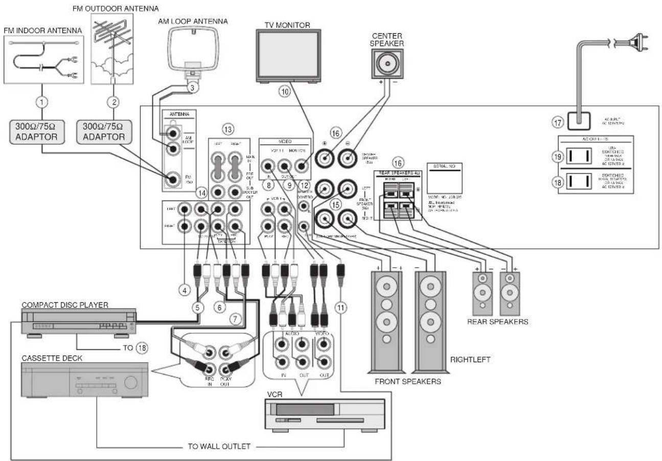
FM INDOOR ANTENNA FM OUTDOOR ANTENNA AM LOOP ANTENNA 300Ω/75Ω ADAPTOR 300Ω/75Ω ADAPTOR TV MONITOR CENTER SPEAKER 10 16 13 VIDEO VCC 11 MONITOR 8 9 12 15 16 REAR SPEAKERS 40 VCC 10 208.25 Rear SPEAKERS AC OUTLE 15 19 18 COMPACT DISC PLAYER TO 18 CASSETTE DECK VCR TO WALL OUTLET FRONT SPEAKERS RIGHTLEFT VCR① FM INDOOR ANTENNA
Connect the supplied antenna (the wire lead) to a 300Ω/75Ω adapter and connect the adapter to the 75Ω T-shaped FM antenna terminal, as shown in the Rear Panel Connection Diagram. Change the position of the antenna until you get the best reception of your favorite stations.
② FM OUTDOOR ANTENNA
An outdoor FM antenna may be used to further improve the quality of reception. Disconnect the indoor antenna before replacing it with the outdoor one. A 75Ω/300Ω adaptor must be used.
③ AM LOOP ANTENNA
Tune in your favorite AM station and position the loop antenna for best reception. Try other stations and find the position that gives the best overall reception. When this unit is mounted in a rack or placed on a shelf with sufficient space behind, hang the antenna on a wall in the direction which gives the best reception.
NOTE: If noise is heard during AM reception, move the antenna for better reception. To prevent undesired noise, the AM LOOP ANTENNA should be located away from the remote control cord over 12 inches (30cm).

text_image
AM LOOP ANTENNA SETTING LEG Stand and place it on a shelf or hang it on a wall.④ TV / AUX INPUT JACKS
This input is provided for any source you want to hear. An additional compact disc player, tape recorder, TV video cassette recorder (VCR), etc. can be plugged into these jacks.
⑤ CD INPUT JACKS
Connect the output cables of a compact disc player to these jacks.
⑥ TAPE PLAY JACKS
Connect the line output of your CASSETTE DECK to these jacks.
⑦ TAPE REC JACKS
Connect the line input of your CASSETTE DECK to these jacks.
⑧ VIDEO / AUDIO INPUT (PLAY) JACKS OF VCR1
Connect these jacks to the corresponding OUTPUT jacks of your TV (if available) or VCR.
⑨ VIDEO / AUDIO OUTPUT (REC) JACKS OF VCR1
Connect these jacks to the corresponding INPUT jacks of a VCR. VIDEO OUTPUT jack: Connect this jack to the VIDEO INPUT jack of the VCR. VIDEO REC jack: Connect these jacks to the AUDIO INPUT jacks of the VCR.
Connect this jack to the VIDEO INPUT jack of a TV/MONITOR.
⑪ REMOTE CONTROL OUT JACK
Connect this jack to the REMOTE IN jack on a JBL or Harman Kardon component. Use one of the accessory mini-plug cables. You can control many other JBL or Harman Kardon components in your system using the JSR 625 remote commander.
⑫ MULTI-ROOM REMOTE IN JACK
Connect a Harman Kardon HE 1000 remote IR sensor to this jack. You can operate the unit by remote commander through the adaptor. It is convenient when the unit is located in a separate room.
⑬ FRONT PRE OUT AND MAIN IN JACKS
Front Pre Out
When a separate power amplifier is used to drive the front speakers, connect the power amplifier input to these jacks.
Front Main In
When a separate pre-amplifier is connected and this unit is used as a power amplifier, connect the pre-amplifier output to these jacks.
NOTE: When you do not use the PRE OUT and MAIN IN separately, always connect the PRE OUT and MAIN IN jacks with a jumper plug.
⑭ SUBWOOFER OUTPUT JACKS
Connect a powered subwoofer to these jacks. This output may also be used for any external component requiring a full bandwidth line-level input.
⑮ SPEAKER TERMINALS
Connect the front left (L) and right (R) speakers to the corresponding terminals. Make sure that the positive (+) and negative (−) terminals on the speaker are connected to the corresponding terminals on the receiver.
⑯ CENTER/REAR SPEAKER TERMINALS
Connect center and rear speakers to the corresponding terminals. When you connect the rear speakers, connect both L and R speakers.
PLEASE NOTE: Sound will not be provided through the rear speakers unless both speakers are connected.
⑰ AC INPUT CORD
Plug this cord in AC outlet on a wall.
⑱ AC SWITCHED OUTLET
These outlets provide AC power. The AC power is switched by the power button. Use this outlet for a CD player or a cassette deck.
⑲ AC UNSWITCHED OUTLET
This outlet provides AC power. The AC power is not switched by the POWER button.
NOTE: Do not plug irons or toasters or other products with high power consumption into these outlets.
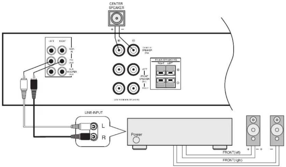
WHEN YOU DRIVE THE FRONT SPEAKERS WITH ANOTHER AMPLIFIER
(Remove PRE-OUT/MAIN IN jumpers when the front speakers are connected to external amplifier.)
text_image
CENTER SPEAKER + - LEFT RIGHT MAIN N OUT 3.56 WOOPER OUT CENTER SPEAKER 20Ω LEFT FRONT SPEAKER 15Ω RIGHT HEART SPEAKERS RIGHT LEFT LINE INPUT L R Power FRONT(left) FRONT(right)WHEN YOU DRIVE THE SUBWOOFER AMP

text_image
FRONT SPEAKER CENTER SPEAKER LEFT RIGHT WIN IN PRE OUT SUB WOOFER OUT CENTER SPEAKER (RUI) LEFT FRONT SPEAKER (RQ) RIGHT (AUG 8 OF MAIN SPEAKERS) REAR SPEAKERS RIGHT LEFT LINE-INPUT L R PS SERIES (made by JBL) SUBWOOFER AMPSURROUND PROCESSING
■ Dolby 3 Stereo
Combines the front and rear signals so that you can enjoy a regenerated sound field which has comparatively more presence and a more expansive feeling from the front 3 channels (front L, front R, center speaker) than that of ordinary stereo regeneration.
■ Dolby Pro Logic Surround
A great number of movies made in recent times have the sound track specially encoded with the Dolby Surround Mode (carrying the [Dolby Stereo] or [Dolby Surround] trademark*).
The front speakers provide the dialogue and the normal stereo effect, while the rear speakers reproduce the surround signals. This position provides excellent results when watching television programs, video software, video discs or video tapes of stereo tele-
vision broadcasts encoded with Dolby Surround. Dolby Stereo films have dramatically changed the role of the movie-goer from that of observer to that of participant. Clearer dialogue, richer music, enveloping ambience and making high-fidelity, multidimensional sound are essential parts of cinematic presentations. Imagine recreating the same sort of audio-visual experience right in your own home.
*Manufactured under license from Dolby Laboratories Licensing Corporation. Additionally licensed under one or more of the following patents: U.S. number 3,959,590; Canadian numbers 1,004,603 and 1,037,877. "Dolby", "Pro Logic" and the double-D symbol are trademarks of Dolby Laboratories Licensing Corporation.
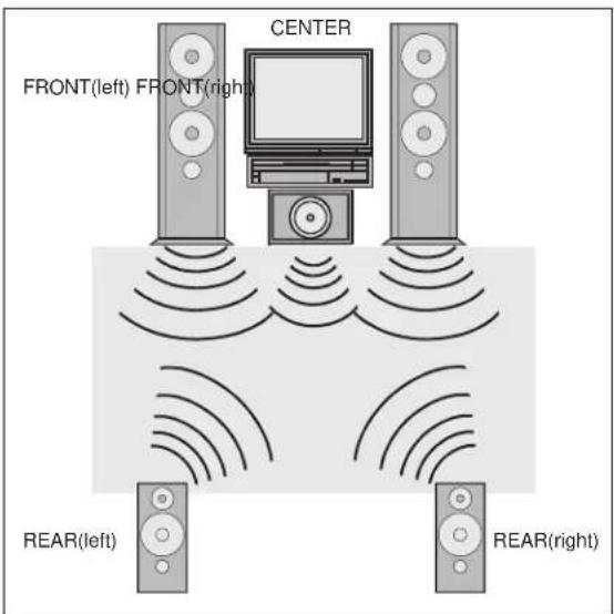
SPEAKER INSTALLATION
■ The JSR 625 incorporates a decoder which reproduces the specially encoded surround sound of Dolby Surround video programs. In Dolby Surround mode, select the speaker operation mode according to your speaker system.

text_image
FRONT(left) FRONT(right) CENTER REAR(left) REAR(right)NORMAL mode
Select this mode if you use a small center speaker. The bass sound of the center channel is output from the front speakers, as a small speaker can't produce enough bass.
text_image
CENTER FRONT(left) FRONT(right) REAR(left) REAR(right)WIDEBAND mode
Select this mode if you use a medium to big center speaker.

text_image
FRONT(left) FRONT(right) REAR(left) REAR(right)PHANTOM mode
Select this mode when you play back a Dolby Surround program source without using a center speaker. The sound of the center channel is output from the front (L and R) speakers.

text_image
FRONT(left) FRONT(right) CENTER3 STEREO mode
Select this mode when you play back a Dolby Surround program source only with the front and center speakers. The sound of the rear channel is output from the front (L and R) speakers.
BASIC OPERATION
1 Press the POWER button to ON then the display panel lights up.
- When using the POWER button on the remote control turn the unit off, the unit will go into STANDBY mode.
2 Select the desired program source with the INPUT FUNCTION SELECTOR buttons and the selected input function appears in the display.
3 Operate the selected component for play back.
- When viewing and listening to video sources, the picture of the video source appears on the television and the sound can be heard from the speakers.
- When playing back video software using a surround sound effect, refer to the "Surround Sound Effects".
- When the TAPE MONITOR button is set to ON so that the TAPE MONITOR indicator lights up, the selected program source cannot be heard from the speakers.
To listen to a program source other than cassette deck be sure to set the TAPE MONITOR button to OFF.
4 Adjust the volume to a comfortable listening level with the VOLUME control or VOLUME UP/DOWN buttons on the remote control.
5 For private listening, insert a 1/4 inch plug of the headphone into the HEADPHONE jack.
- When the headphones are plugged in, sound from the speakers is cut off.
LISTENING TO BROADCASTS
You can use auto, manual or preset tuning to select a radio station.
AUTO TUNING
If broadcast signals are strong and there is no interference, auto tuning is possible.
1 Press the FM or AM button to select the desired band.
2 Press the SEEK STEREO button.
3 Press the UP or DOWN TUNE/PRESET button. Tuning will start automatically and stop at a broadcast station frequency with sufficient signal strength.
■ MANUAL TUNING
Auto tuning may be impossible if the broadcast signal is weak. If so, use manual tuning.
1 Press the FM or AM button to select the desired band.
2 Press the UP or DOWN TUNE/PRESET button until the desired station frequency is reached.
• Each time the button is pressed, the frequency changes by a step.
- When the button is kept pressed, the frequency changes continuously in sequence.
PRESET TUNING
The receiver has a memory for up to 30 preset stations. If the station frequencies are stored in this memory, they can be tuned in by a simplified procedure.
■ MANUAL PRESETTING
Up to 30 stations can be preset at random, regardless of the reception band.
1 Tune in the station to be memorized using the auto or manual tuning.
2 Press the MEMORY button, then the MEMORY indicator lights up for 5 seconds.
3 Select the preset number with the UP or DOWN TUNE/PRESET button while the MEMORY indicator is lit.
4 Press the MEMORY button to memorize the station.
- When using the NUMERIC buttons on the remote, the station is memorized without pressing the MEMORY button again.
- When selecting one digit preset numbers with the NUMERIC buttons, press the corresponding number without "0".
5 Repeat steps 1 to 4 to preset other stations.
■ RECALLING THE PRESET STATIONS
Select the preset number of the desired preset station with the UP or DOWN TUNE/PRESET or NUMERIC buttons on the remote control unit.
■ SCANNING THE PRESET STATIONS IN SEQUENCE
1 Press the PRESET SCAN button on the remote control unit to listen to the preset stations.
2 The receiver will start scanning the stations in the preset sequence and each station is received for 4 seconds.
3 At the desired station, press again to stop scanning.
NOTES:
- If the end of the frequency range is reached during the auto or manual tuning, tuning will continue from the opposite end.
- When FM stereo broadcasts are poor, select the FM mono mode with the SEEK/STEREO button so that the AUTO indicator goes off.
- When memorizing a new station, the previously memorized station on the same channel number is cleared.
- In the event of a power failure or when the receiver is disconnected from the AC outlet, the memorized stations are maintained for approximately 2 weeks.
■ RECORDING WITH A CASSETTE DECK
1 Select the program source to be recorded with the INPUT FUNCTION SELECTOR buttons.
2 Start recording on the cassette deck.
3 Play back the desired program source.
- The volume, balance, bass and treble settings have no effect on the recording or dubbing.
- When recording is performed on a 3-head cassette deck, the recorded sound can be monitored through the speakers by pressing the TAPE MONITOR button to ON.
■ DUBBING FROM VCR2 TO VCR1
1 Press the VCR2 button as a program source to be recorded.
2 Start recording on the VCR connected to VCR1.
3 Play back on the VCR connected to VCR2, then the video and audio signals from VCR2 will be dubbed onto VCR1.
■ RECORDING WITH SEPARATE VIDEO AND AUDIO SOURCES
When dubbing from VCR2 to VCR1, you can replace the audio signal from VCR2 with the audio signal from other program sources.
1 Press the VCR2 as a video source to be recorded.
2 Select the audio source to be recorded with the INPUT FUNCTION SELECTOR buttons.
3 Start recording on the VCR connected to VCR1.
4 Play back on the video and audio components, allows you to watch the picture from the video component on the television and listen to the sound from the audio component through the speakers while recording.
NOTE: Be sure to observe the order of steps 1 and 2.

text_image
1 2 3 4 5 6 7 8 9 0 1 2 3 4 5 6 7 8 9 0 Disc Search Skip CD Tuner A-B Info Tape Mon Cass Deck Aux Select A-B VCR 1 VCR 2 7 8 Delay Surround Off 3-Stereo Pro-Logic Center Level Cent Mode Test RearLevel Master Volume Display Sleep Mule 10 11 13 14 15 16 UBL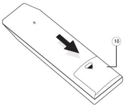
natural_image
Isometric line drawing of a rectangular device with an arrow pointing to a small circular feature, labeled with number 18 (no text or symbols on the device itself)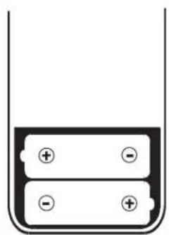
natural_image
Simple diagram of a battery inside a container with two positive and negative terminals (no text or symbols)① INFRARED TRANSMITTER WINDOW
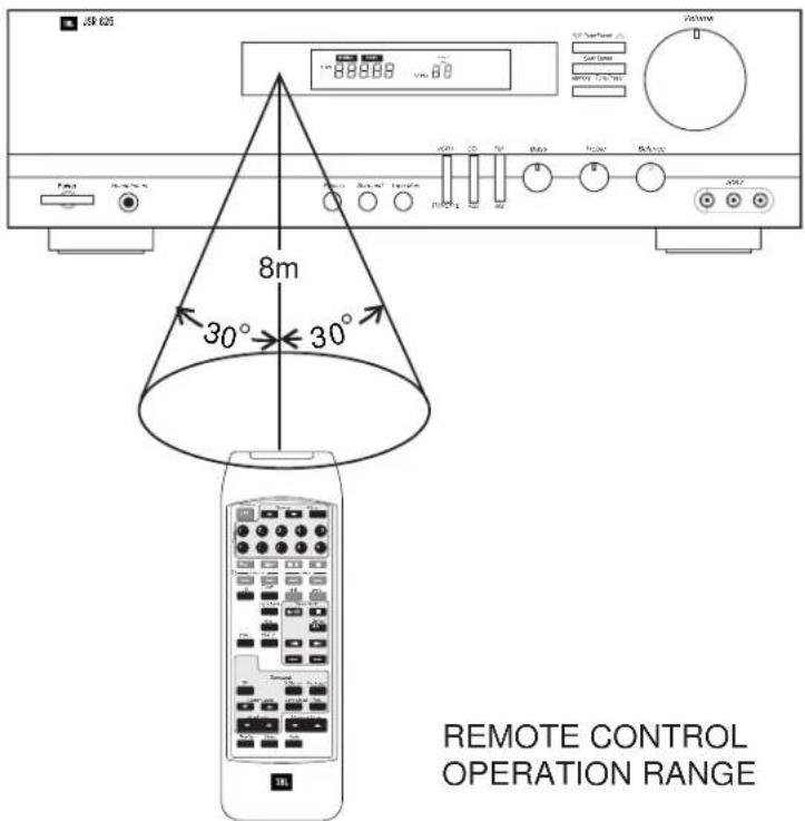
The infrared beam is emitted forward from this window when you press any button on the commander. For the remote controls to function properly, always face this window toward the remote sensor window on the receiver and do not obstruct this window with any material.
② STANDBY BUTTON
Press this button to turn the power on and off.
Automatic power on: When you press the input function buttons (CD, TUNER, TAPE, TV/AUX, VCR 1, VCR 2) in STANDBY mode, the power is automatically turned on and the function is selected.
③ TUNING UP/DOWN
Press these buttons to tune the receiver up or down.
④ PRESET SCAN BUTTON
Button for scanning preset station frequencies (see page 11).
⑤ NUMERIC BUTTONS
These buttons can be used for preset tuning in TUNER mode.
Preset tuning: Press the TUNER button to change the input function of the receiver to TUNER and then select one of 30 preset locations.
⑥ CD FUNCTION BUTTONS
For a CD PLAYER: DISC (DISC SELECTOR is available for the Harman Kardon FL8400, FL8450 CD changer), PLAY, PAUSE, STOP, BACKWARD SKIP, FORWARD SKIP, A-B and INTRO buttons are available.
When selecting a disc, press the DISC button.
⑦ CASSETTE DECK FUNCTION BUTTONS
For a cassette deck: PAUSE/RECORD, STOP, REVERSE PLAY, FORWARD PLAY, REWIND, FAST FORWARD buttons are available.
⑧ DELAY TIME BUTTON
This button operates only in DOLBY PRO LOGIC mode. In this mode the output signal from the surround speakers is delayed slightly from that of the front speakers.
Select appropriate delay time to achieve the best surround sound effect. For Dolby Surround sound, we recommend a 20ms delay. The time is changed as below, when the button is pressed in succession.
text_image
8m 30° 30° REMOTE CONTROL OPERATION RANGEPress the button to select the desired input function. The available buttons are CD, TUNER, TAPE, TV/AUX, VCR 1, and VCR 2.
⑩ CENTER LEVEL UP/DOWN BUTTONS
Use these buttons to adjust the sound level of the center speaker to that of the front speakers. These buttons work only in DOLBY PRO LOGIC and DOLBY 3 STEREO mode. These buttons do not work in PHANTOM mode.
⑪ CENTER MODE BUTTON
Select the CENTER mode.
⑫ TEST TONE BUTTON
Generates test sounds in all channels (Left, Center, Right and Surround) in succession.
These buttons operate only in Dolby PRO LOGIC mode. Use these buttons to adjust the sound level of the surround speakers. Set the MASTER VOLUME control at the desired level and press the UP or DOWN button until you get the optimum surround effect at your listening position.
⑭ MASTER VOLUME BUTTONS
Adjust the overall (Front, Center, and Rear) volume level.
⑮ DISPLAY BUTTON
Press once and the display dims, press again and it turns off. Press a third time and it goes on.
⑯ SLEEP BUTTON
Set the receiver to automatically turn off after 10, 20, 30, 60, or 90 minutes. Each time the button is pressed, the setting is advanced as below.

The display will dim when the sleep function has been set.
⑰ MUTE BUTTON
Press this button to silence the speakers temporarily. The volume indicator blinks. Press again to restore the same listening level as before.
⑱ BATTERY COMPARTMENT
This battery case is provided as the power source for the commander. To remove the cover, press it down with your thumb and pull it toward the back side. Two UM-3, size "AA" or R6 1.5V dry batteries are used. When loading the batteries, make sure that the polarity is correct. Remove the batteries from the case if the remote commander will not be used for a long time.
This unit is designed for trouble-free operation. Most problems users encounter are due to operating errors. So, if you have a problem, first check this list for a possible solution. If the problem persists, consult your authorized JBL Service Center.
| IF THE PROBLEM IS... MAKE SURE THAT THE... | |
| No lights illuminate when POWER button is pressed Unit is plugged into a live outlet | |
| No sound is heard Correct input function selector button has been pressed | Volume is turned upSpeakers are connected properly |
| Dolby Surround does not work on center and rear channels Correct surround mode is selectedRear and Center levels are turned up | |
| Selecting video component produces sound but no picture Video cables are connected properly | |
| The TV picture does not match the sound Video sources are properly connected to receiverVideo/Antenna Switch on TV is set to Video | |
| No output from one or more channels Cables are not defective: Check/replace speaker cablesThe signal source is operating and providing proper signal output to the JSR 625 | |
| No center channel output Dolby surround or movie mode is turned on | PHANTOM mode is not active |
| Tuner sound has a large amount of interference, or The antenna is properly connectedThe “Stereo” display is not illuminated, or The antenna is properly locatedTuner sound distorts and/or volume level is too low The antenna is set in the proper directionThe antenna is adequate to receive the desired station | |
| Tuner is intermittent or continuously buzzing or hissing The unit is away from fluorescent lights, TVs, motorsand other electrical appliances | |
| Stations cannot be preset After pressing the MEMORY button, the PRESETbutton is pressed while the MEMORY indicator blinks | |
STEREO MODE
Continuous Average Power (FTC)
35 Watts from 20Hz–20kHz: ......@< 0.09% THD, both channels driven into 8 Ohms
FIVE CHANNEL SURROUND MODE
Continuous average power per channel (FTC)
Front L&R channels
30 Watts from 20Hz-20kHz: @< 0.3% THD, both channels driven into 8 Ohms
Center channel
30 Watts at 1kHz:......@< 0.3% THD, driven into 8 Ohms
Rear channels
20 Watts at 1kHz:......@< 1.0% THD, both channels driven into 8 Ohms
AMPLIFIER SECTION
High-Instantaneous Current Capability (HCC): ± 20 Amps
Negative Feedback: 20dB
Frequency Response @1W (+0/-3dB): 0.5Hz - 100kHz
Rise Time: 1.8μSec
Transient Intermodulation Distortion (TIM): Unmeasurable
PREAMPLIFIER SECTION
Signal-to-Noise Ratio (ref. 1 Volt, A-Wtd)
CD: 92dB
Video: 83dB
Input Sensitivity/Impedance
Video, CD, Tape: 150mV/22kW
Tone Control Range
Bass @ 50Hz: ±10dB
Treble @ 10kHz: ±10dB
TUNER SECTION: FM
Usable Sensitivity, Mono (dBf):....11.2
50dB Quieting Sensitivity, Stereo (dbf): 40.3
Signal-to-Noise Ratio @ 65dBf, mono/stereo:....70dB/65dB
Capture Ratio: 2.0dB
Selectivity, Adjacent/Alternate Channel: 5dB/65dB
IF Rejection: 90dB
AM Rejection @ 45dBf: 55dB
Stereo Separation @ 1kHz, 65dBf: 45dB
THD @ 1kHz, 65dBf, mono/stereo (%): 2/4
TUNER SECTION: AM
Sensitivity, External Antenna: 25μV
Alternate Channel Selectivity: 38dB
Image Rejection: 35dB
IF Rejection: 50dB
Dimensions (HxWxD): 4-7/8 x 17-5/16 x 14-15/16"
125 x 440 x 380mm
Weight (lbs/kgs): 18 lbs, 8.2 kg
Depth measurement includes knobs, buttons and antennas.
Height measurement includes feet.
All features and specifications are subject to change without notice.
JBL
JBL Consumer Products, Inc.
80 Crossways Park West
Woodbury, NY 11797
8500 Balboa Boulevard
Northridge, CA 91329
1-800-349-4JBL
H A Harman International Company
Part No. JSR625OM