GTQ100 - Receiver JBL - Free user manual and instructions
Find the device manual for free GTQ100 JBL in PDF.

| Product Type | Audio/Video Receiver |
| Model | GTQ100 |
| Brand | JBL |
| Dimensions (W x H x D) | 430 x 340 x 130 mm (16.9 x 13.4 x 5.1 inches) |
| Weight | 10.5 kg (23.1 lbs) |
| Power Supply | AC 120V/240V, 50/60Hz |
| Power Consumption | 800W (maximum) |
| Output Power (RMS) | 100W per channel (8 ohm, 20-20kHz) |
| Speaker Impedance | 4-16 ohms |
| Total Harmonic Distortion | <0.05% |
| Input Sensitivity | 200 mV |
| Signal-to-Noise Ratio | ≥95 dB |
| Audio Inputs | 4 stereo RCA, 1 optical, 1 coaxial |
| Audio Outputs | Front, Center, Surround speakers; Subwoofer pre-out |
| Video Inputs | 3 HDMI, 1 composite |
| Video Outputs | 1 HDMI with ARC |
| Supported Audio Formats | Dolby Digital, DTS, PCM |
| Functions | FM/AM tuner, Bluetooth, USB playback, EQ presets |
| Remote Control | Included (batteries not included) |
| Maintenance | Wipe with a dry, soft cloth; avoid solvents |
| Safety | Disconnect from mains when not in use; keep away from moisture |
| Spare Parts & Repairability | Contact JBL customer service or authorized service centers |
Frequently Asked Questions - GTQ100 JBL
User questions about GTQ100 JBL
0 question about this device. Answer the ones you know or ask your own.
Ask a new question about this device
Download the instructions for your Receiver in PDF format for free! Find your manual GTQ100 - JBL and take your electronic device back in hand. On this page are published all the documents necessary for the use of your device. GTQ100 by JBL.
USER MANUAL GTQ100 JBL
natural_image
Abstract geometric shape with white triangular form against black background (no text or symbols)
natural_image
Simple geometric shape: a white triangle on black background (no text or symbols)Features
• 4 Channel Operation
• Built-in Electronic Crossover
- Minimal Negative Feedback
- Quiet Start Circuitry
- Independent Front and Rear, Continuously Adjustable Gain Controls
• Rated for 2-ohm operation
- Low Noise Input Section
• Gold-plated RCA Connectors
• Balanced Speaker Level Inputs
- JBL Proprietary, Solid Brass Heavy Duty Screw-down Speaker Output Connectors
- Input Channel Selector Switch
- Remote Turn On Circuitry with Power On Indicator
• Fully Protected Against All Installation Errors
• Second-order, 12 dB per octave Capacitive/Inductive Power Supply Input Filtering
Owner's Warranty Information Records
| Model Number |
| Serial Number |
| Dealer Name |
| City, State, Zip |
| Sales Receipt Number |
| Date of Purchase |
JBL
GTQ100
Specifications
| Maximum Power Output (into 2 ohms) | 100 Watts | |
| Power Output (20-20k Hz, 14.4V battery voltage) | 18 Watts × 4(4 ohms, 0.5% THD) | |
| 25 Watts × 4(2 ohms, 0.5% THD) | ||
| Signal-to-Noise Ratio | 95 dBA | |
| Frequency Response | 10-35k Hz (±3 dB) | |
| Input Sensitivity (for rated power output) | Line Level Input: | 150 mV to 1.5V |
| Speaker Level Input: | 2.5V to 25V | |
| Input Impedance | Line Level Input: | 11k ohms |
| Speaker Level Input: | 100 ohms | |
| Minimum Speaker Impedance | 2 ohms | |
| Built-in Electronic Crossover Frequency and Slope | 80 Hz, 12 dB per octave | |
| Power Requirement | 11 to 16V DC negative ground | |
| Fuse Size | 15A | |
| Size (inches, L × W × H) | 11-1/8 × 4-1/4 × 2-3/8 | |
GTQ100
JBL
Introduction
Thank you for selecting a JBL power amplifier for your car audio system.
The GTQ100 is an extremely flexible device. It accepts two or four channel inputs. The inputs can be either preamp level or speaker level signals. Its four channels of amplification can be used to drive four full range speakers. Or the internal electronic crossover can
be used to biamplify the system. Separate gain controls for the two sections of the amplifier provide complete control over the sound balance of the system.
The extremely stable output circuitry of the JBL GTQ100 enables it to drive 2 ohm speaker loads.
About Installation
The GTQ100 is a sophisticated product that requires proper installation to realize its full performance potential. Skill with tools, an understanding of basic electronics, and experience with car stereo installation are needed to properly install the GTQ100. If you do not have the necessary knowledge and skills. We strongly Recommend That The Installation Be Done By An Authorized JBL dealer.
If you choose to install the GTQ100 yourself read ALL of the information in this manual BEFORE, you start the
installation. Pay patticular attention to the safety precautions and notes.
Plan the complete installation before you start. The routing of wires, the power supply connection points, and the mechanical installation of the unit should be completely planned before you begin. Work carefully and check each step as it is performed. Before operating the amplifier, recheck the entire installation to be sure that each connection is correct, properly insulated and secure.
JBL
GTQ100
Associated Equipment
The GTQ100 can be driven with either speaket level or preamp level inputs. Always use preamp level inputs if the source unit has preamp level outputs. It will keep the overall system distortion lower.
The input level controls can be used to match the sensitivity of the GTQ100 amplifier to the output signal of the source. This matching is important to keep noise levels low.
When only one speaker is connected to each channel virtually any speaker may
System Configurations
There are several different types of applications in which the GTQ100 may be used. Below and on the following page are a table and diagrams showing
be used. However, if two speakers are connected in parallel to a given channel, each speaker must have an impedance of at least 4 ohms to insure that the impedance load does not drop below 2 ohms. Impedance loads lower than 2 ohms will overload the amplifier output stage and activate the protection circuits
The GTQ100 must NOT be used with speakers that have one of their input terminals wired to the frame of the speaker or to the chassis of the vehicle.
typical ways in which the GTQ100 is used in systems and how to set the input and crossover switches for each application.
Switch Settings
| Application | |||||
| A | B | C | D | ||
| Input Channel Switch | 2 CH | ||||
| 4 CH | |||||
| Crossover | On | ||||
| Off | |||||
GTQ100
JBL
Typical Applications
Application A

flowchart
graph TD
    A["Signal Source"] --> B["Preamp outputs"]
    B --> C["Left Front GTQ100"]
    B --> D["Right Front GTQ100"]
    C --> E["Front Speakers L R"]
    C --> F["Back Speakers L R"]
Two channel output from cassette/CD. Both sections of the GTQ 100 are driving a pair of full range speakers.
Application B
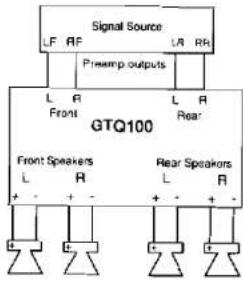
text_image
Signal Source LF RF L R Prewamp outputs L A Front L A L R GTQ100 Rear Front Speakers L R L R + - + - + - - + - + - + -Four channel output from cassette/CD. Both sections of the GTQ 100 are driving a pair of full range speakers.
Application C

flowchart
graph TD
    A["Signal Source"] --> B["Presamp outputs"]
    B --> C["Right Front"]
    B --> D["Left Front"]
    C --> E["GTQ100"]
    D --> E
    E --> F["Front Speakers"]
    E --> G["Rear Speakers"]
    F --> H["L"]
    G --> I["R"]
    H --> J["+"]
    I --> K["+"]
Two channel output from cassette/CD. Front section of GTQ 100 driving 2 full range speakers, rear section driving 2 subwoofers.
Application D

text_image
Signal Source LF RF LR RR Preamp outputs L R Front L R L R Rear GTQ100 Front Speakers L R + - + - + - Rear Speakers L R + - + -Four channel output from cassette/CD. Front section of GTQ 100 driving 2 full range speakers, rear section driving 2 subwoofers.
JBL
GTQ100
Installation Precaution
Before beginning the installation of the amplifier read the following precautions carefully. Failure to heed these warnings could result in personal injury or damage to property.
The GTQ100 should be installed only in vehicles that have 12 volt negative ground electrical systems. Connection to other types of electrical systems may damage the amplifier and/or the vehicle's electrical system.
Before beginning the installation, disconnect the negative (ground) cable to the vehicle's battery. This will prevent accidental short circuits while working on the installation. Reconnect the cable only after the installation is complete and the wiring has been carefully checked to be sure there are no exposed wires or short circuits and everything is properly and securely connected.
Work in an area that is well ventilated. Wear eye protection whenever cutting, drilling or filing any parts of the vehicle.
Before cutting or drilling any holes in the vehicle inspect the area carefully to be sure there are no electrical wires, hydraulic brake lines, fuel lines, or fuel tanks that may be damaged while doing so. Such components may be hidden within double-walled panels or structural members of the vehicle, so be extremely cautious.
Do not bypass or modify the fuse in the main +12 volt power supply wire. Do not replace the fuse with one rated for higher current levels. Doing so could result in damage to the amplifier and the vehicle's electrical system and could be extremely hazardous. Repeated blowing of the power supply fuse indicates improper operation or problems in the installation.
It is recommended that an additional power supply fuse be installed in the +12 volt power supply wire as close as possible to the battery terminal. This minimizes the chance of electrical system damage or fire in the event of a short circuit in the power supply wire.
GTQ100
YBL
Physical Installation
There are several factors to consider when selecting a mounting location for the GTQ100. It must be solidly mounted in a place where it will not be subjected to excessive shock and vibration. Under no circumstances should the amplifier be mounted where it will be exposed to moisture or extreme heat. Try to mount the GTQ100 where the main +12 volt power supply wire, which must be connected directly to the battery, can be kept relatively short.
The GTQ100 must be mounted in a place where air can circulate around the fins on the chassis. Good air circulation around the amplifier will
make it operate at lower temperatures and reduce the chance of the thermal protection circuits being triggered. The installation positions that provide the most efficient air circulation around the amplifier are shown below.
Use a mounting location that allows access to the wiring connections and level adjustments. Then the amplifier can be mounted before these connections and adjustments are made. If the amplifier must be mounted in a somewhat inaccessible location, it may be easier to mount it after the wiring connections and level adjustments are complete.
Mounting Positions

text_image
GOOD-Vertical Mounting AIR FLOW GOOD - Horizontal Mounting AIR FLOW NEVER - Mount Upside Down Restricting SurfacesJBL
GTQ100
GTQ100
JBL
Mounting
Place the amplifier in the installation location. Use a marking pen to mark the four mounting screw hole locations. Set the amplifier aside and drill the holes for the mounting screws. (Note: If the panel on which the amplifier is being mounted is covered with carpeting or upholstery, cut a small "x" in the material at each screw hole location before drilling the holes.
Wiring
Proper wiring of the GTQ100 and the associated components is extremely important for proper performance and long-term reliability. Using the proper type of wire is very important. If a specific type of wire should be used for a certain application, it will be noted.
Route the wiring through the car carefully. Do not allow wires to lay against sharp sheet metal edges or any other surfaces that might wear away or cut through the insulation of the wire. Use strain reliefs, rubber grommets and plastic tubing to protect the wires whenever they are run through sheet metal panels or are placed where they might be pulled or damaged.
This will help prevent tearing or stretching of the material and carpet fibers from being pulled out.) Set the amplifier fibers from being pulled out.) Set the amplifier in position and align the holes in its end panels with the holes previously drilled. Put lock washers on the four sheet metal screws provided and drive them into the mounting panel. Tighten the screws evenly until the unit is solidly mounted.
To keep noise levels as low as possible do not place audio signal wires alongside the power wires for the amp or the vehicle's standard power wires. When wires are run from the front of the vehicle to an amplifier mounted in the trunk, run the power supply wires down one side of the vehicle and the audio signal wires down the other. Avoid routing any wires near accessories such as ignition control modules, fuel pumps, or fan motors.
To ensure long-term reliability, all wire-to-wire connections should be soldered and insulated with electrical tape or heat-shrink tubing. Never leave bare wire exposed. Terminate wires with solder-on lug terminals whenever appropriate.
Wiring Diagram
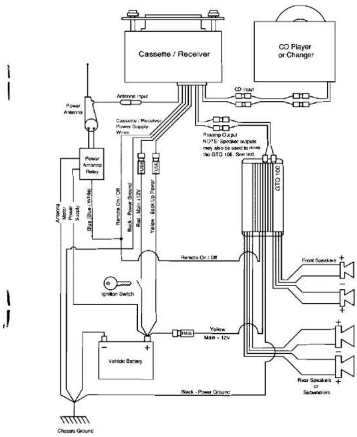
flowchart
graph TD
    A["Cassette / Receiver"] --> B["Antenna Input"]
    A --> C["CD Player or Changer"]
    B --> D["Cassette / Receiver Power Supply Wires"]
    C --> E["GTO 100"]
    D --> F["Remote On / Off"]
    F --> G["Yellow Back Up Power"]
    G --> H["Black - Power Ground"]
    H --> I["Vehicle Battery"]
    I --> J["Ignition Switch"]
    J --> K["Chapsis Ground"]
    L["Power Antenna"] --> M["Power Antenna Relay"]
    M --> N["Blue (Blue White)"]
    N --> O["Remote On / Off"]
    O --> P["Buck Power Ground"]
    P --> Q["Rel. Main +12V"]
    Q --> R["Yellow Back Up Power"]
    R --> S["Remote On / Off"]
    S --> T["Yellow Main +12V"]
    T --> U["PULSE"]
    U --> V["Front Speakers +"]
    U --> W["Rear Speakers or Subworkers +"]
    X["Antenna Motor Power Supply"] --> Y["Blue (Blue white)"]
    Z["Chapsis Ground"] --> AA["-"]
JBL
GTQ100
GTQ100
JBL
Power Supply Connections
The power input and remote on/off wires are connected to the GTQ100 via the wires that extend from the end panel.
BAT (+) (Yellow) — The GTQ100 will draw as much as 15 amps from the vehicle's electrical system. The standard power wiring in the vehicle would be overloaded by such current demands. So the +12 volt power supply wire must be connected directly to the positive (+) terminal of the vehicle's battery. Connect a heavy (10 gauge or larger) heat and oil resistant extension wire to the main +12 V input wire. Connect the other end to the positive (+) terminal of the battery.
Ground (Black) — Proper grounding is extremely important. It has a significant effect on the overall performance and noise level of the system. The ground wire must be solidly connected to a major sheet metal structure of the vehicle. Usually the power ground wire can be connected to a sheet metal panel near the amp mounting location. Scrape all paint and primer off the sheet metal at the grounding point to ensure a good electrical connection. Attach the wire to the grounding point with a sheet metal screw and lock washer or a bolt/lock washer/nut set.
In some vehicles, such as those that have non-metal bodies, it may be necessary to extend the power supply ground wire and connect it directly to the negative (-) terminal of the battery. Use heat and oil resistant 10 gauge or larger stranded copper automotive wire.
Solder and insulate all connections. Keep the extension wire as short as possible. Solder a terminal on the wire and connect it to the battery terminal.
In some installations the noise level will be lower if the GTQ100 is grounded to the same point the head unit is grounded.
Remote turn-on — The remote power control system turns the GTQ100 not in use to prevent discharging of the vehicle battery. When a +12 volt “turn on signal” is applied to the remote turn on wire the amplifier is turned on. A red LED on the end panel of the amplifier lights whenever the amplifier is turned on. If the head unit has a +12 volt automatic antenna activation wire, the remote turn on wire may be connected to it. Some head units have no automatic antenna activation wire. Other decks have automatic antenna wires that are “on” only when the radio is used, the +12 volt turn-on signal is cut off when a tape is played. In such cases, the remote turn on wire may be connected to the standard radio or accessory wiring. An unused accessory terminal in the fuse block of the vehicle can be used. Or any other +12 volt source that is turned on and off with the vehicle’s ignition switch may be used. The remote on/off system draws only a small amount of current so a relatively small (18 or 20 gauge) extension wire may be used to connect the remote on/off voltage source. Be sure to solder and insulate the wire-to-wire connections.
Input Connections
Line Level Input — Proper wiring between the signal source, any other components in the system, and the GTQ100 will help keep noise levels in the system low. Use high-quality, low capacitance shielded wire. Keep the wire as short as possible. Do not splice together shielded wires. The inputs of the GTQ100 accept standard phono plugs (also called RCA plugs). The outputs of most head units, equalizers or crossovers also accept phono plugs. If another type of connector is used some adaptors or special cables may be needed. Proper wire and connectors can be obtained from any JBL authorized installation specialist.
Speaker Level Input — When the high level (speaker level) outputs of a cassette/CD player are used to drive the GTQ100, the signal goes into the amp through a special 8 wire harness and connector. If extension wires must be used to connect the speaker output from the cassette/CD player to the GTQ100 high level inputs use 18 gauge speaker wire. Keep such extension wires as short as is practical and do not run them outside the passenger and trunk compartments. Use the color code of the input wire harness and the cassette/CD player output wires to be sure the left/right channel orientation, and the positive/negative orientation, of each connection is correct. For example, the left positive output of the cassette/CD player must be connected to the left positive input of the GTQ100. The color code for the high level input wire harness is:
| Left Front + | White/ |
| Left Front - | White/Black |
| Right Front + | Grey |
| Right Front - | Grey/Black |
| Left Rear + | Green |
| Left Rear - | Green/Black |
| Right Rear + | Purple |
| Right Rear | Purple/black |
When the cassette/CD player that has "floating ground" speaker output circuit is used to drive the high level inputs of the GTQ100, some unusual input connection methods may be needed in order to minimize noise levels in the system. Discuss such connection methods with a professional car stereo installer.
NOTE: The GTQ100 has a built in 80 Hz subwoofer crossover. Be sure the subwoofer on/off switch is properly set for the system configuration. If you have any questions about how to set this switch, contact your authorized JBL dealer.
To prevent inductive noise pick-up from the vehicle's power supply wiring, do not run audio signal wires alongside the power wiring for the amplifier or the vehicle's standard power wiring.
Input Channel Selector — The input configuration switch is set according to the number of preamp inputs from the cassette/CD unit that are connected to the GTQ100.
JBL
GTQ100
GTQ100
JBL
Speaker Connections
IMPORTANT THE SET-SCREWS ON THE TERMINAL BLOCKS MUST BE TIGHTENED ONLY WITH A #0, FLAT BLADE SCREW DRIVER SUCH AS XCELITE R184. DO NOT OVERTIGHTEN THESE SCREWS.
When connecting speaker wires, be sure that no uninsulated wire remains exposed and no loose strands of wire touch an adjoining wire or terminal or metal surface.
The GIQ100 has two sets of set screw type connectors for the speaker wires. The right side row of connectors is for the "front" speakers and the left side row is for the "rear" speakers. The connectors are marked "L" and "R" for the right and left speakers respectively. The speakers wires are connected to the positive and negative terminals for the associated left and right speaker.
To get proper bass response and stereo imaging, all the speakers in the system
must be "in phase". The input terminals of the speakers will be marked in the some way to identify one as positive (+) and the other as negative (-). Make sure the positive (+) speaker terminal is attached to the positive (+) amplifier connection in every speaker-to-amp connection. All two-conductor speaker wire has one conductor marked in some way so it can be traced.
Use high-quality speaker wire for the amplifier to speaker connections. Wire that is 16 gauge or larger should be used. Larger wire or special high performance speaker cables may improve the performance of some systems.
Be very careful when speaker wire is routed through a door hinge area to door-mounted speakers. Use grommets and stain reliefs wherever necessary to prevent damage to the wires.
Input Connections
text_image
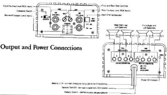
Output and Power Connections Front Pre-Amp Level RCA Inputs Crossover Switch Balanced Speaker Level Itopes Power and Power Control Rear-Amp Level RCA Inputs Input Chiral Substrate Rear High and Left Spreads Front High and Left Spreads Power On Indicators Battery (c) In - connect directly to the (c) terminal of the battery Remote Turn On - contact to switch +12V source Battery Ground - connect to specific output groundOperation
Before operating the GTQ100 recheck all wiring connections to make sure they are correct and secure. Be sure that specified fuse or fuses are properly installed in the +12 volt power supply wire. Reconnect the negative ground (−) terminal of the battery. Make sure the crossover on/off switch and input channel selector switch are properly set.
Gain — The setting of the gain controls on the GTQ100 is important to ensure proper performance, low noise levels, and maximum reliability in the system. As a general rule, the controls should set as low as possible while still providing adequate volume levels. Using a high signal level from the source and a low input sensitivity setting on the amplifier will help keep noise levels in the system low.
To adjust the system, start with the amplifier gain controls fully counterclockwise. Adjust the volume control of the head unit to a point between 12 and 14 of full volume. Some head units have additional output level controls. Set these to their maximum position. Set the level controls on any associated equipment such as equalizers and electronic crossovers to their maximum position also. If this setting does not provide adequate volume levels, gradually increases (turn clockwise) the gain cocontrol(s) of the GTQ100. Stop increasing the gain
control(s) when the system plays as loud as necessary or when the first signs of distortion are heard.
The gain controls on the GTQ100 can also be used to balance the sound of multi-speaker systems. These adjustments can be complex. Your local JBL authorized autosound installation specialist is the best person to help with such adjustments.
Turn-On Delay — When installed as described in this manual, the GTQ100 will turn on and off with the head unit or the vehicle's ignition switch. When the amplifier is turned on, there is a time delay of several seconds (longer in cold weather) before the amplifier will produce sound. This reduces the chance of annoying noises being produced when the amp is turned on.
Power Consumption — Operating the GTQ100 when the vehicle is not running will discharge the battery. Under normal operating conditions, the units will draw 2-5 amps from the battery. At high volumes, the amplifier can draw as much as 15 amps for brief instants. After even a short period of time, this current drain can discharge the battery to the point that it will not start the vehicle. Power consumption under “no signal” conditions is less than 0.4 amps. Even this small power usage can discharge a battery over several hours time.
JBL
GTQ100
Overload Protection — The GTQ100 incorporates elaborate protection circuitry to prevent damage to the amplifier circuitry and ensure reliable operation. If the amplifier cycles on and off, or does not work at all, a problem in installation or an abnormal electrical condition is indicated. Check speaker wiring for short circuits or impedance loads below 2 ohms. Check the power supply voltage at the input of the amplifier to be sure that it is normal (11-16 volts).
If the GTQ100 is operated at very high power level in a high ambient temperature situation, the unit may not be able to radiate all the heat generated by such operation. If the temperature of the amplifier reaches a level that could cause damage, the
Noise Suppression
The power supply system of every vehicle has some electrical "noise" that is generated by the ignition system, the alternator, the accessories, and their wiring. High performance audio equipment is more likely to pick up such noise than conventional equipment because it has wide frequency bandwidth and high gain (amplification) circuits. The GTQ100 has built in power supply filters to help prevent noise problems. If noise occurs it is probably the result of improper installation. The following suggestions will eliminate most noise problems.
Determining the Source of the Noise — Often noise in a system is picked up by the signal source. Before attempting to eliminate noise from the "amp" be sure
thermal overload protection circuit will turn the amplifier off. It will run the amp back on again when it cools off. Repeated activation of the protection circuit indicates that the system is being improperly operated or that the amplifier should be relocated to an area that has a lower ambient temperature and/or that allows more air circulation around the unit.
Fuse Replacement — If the fuse(s) in the main +12 volt power supply wire must be replaced, DO NOT use a fuse rated for higher current levels. The maximum fuse size for the GTQ100 is 15 amps. Do not bypass or modify the fuse or fuse holder. Exceeding the standard fuse size or bypassing the fuse holder will void the warranty and may cause serious damage.
it is not being picked up by the signal source and then passed on to the amp.
Grounding — Most noise problems are caused by inadequate grounding. The head unit, the amplifier and any other components must be grounded to a major metal member of the vehicle's frame. In modern vehicles, some of the structural elements may be plastic.
Often the noise level in the system will be lower if the amplifier is grounded to the same point the head unit is grounded. If this does not adequately reduce the noise level try another grounding point on the car frame. Some grounding points may work better than others. In some instances grounding the head unit and/or amplifier directly to the battery will provide the best results.
GTQ100
External Power Line Filters — The built-in power supply filter of the amplifier makes external filters unnecessary. In some cases, power supply noise can enter the system through the head unit power supply. Putting a filter on the head unit power supply input may then be necessary.
Suppression of Noise Sources -- Common noise problems will be solved by proper grounding and power supply connections. However, there are many noise suppression devices (such as spark plug and coil lead suppressors and rotor and coil bypass capacitors) available at auto parts or car stereo stores. There are also noise suppressors that can be connected directly to the alternator that are effective in some situations. The use of any such
suppressor should be discussed with a JBL authorized installation specialist. Certain vehicles are particularly "noisy", especially models that have solid-state ignition systems or that have non-metal bodies. Such vehicles may require electrical noise suppression devices which are not normally required.
Antenna — A common noise problem is generated by a "ground loop" produced by the antenna shielded cable being grounded at both the antenna mounting point and at the radio input. In this instance, insulate the antenna ground from the chassis of the vehicle at the antenna mounting point so the antenna shield is grounded only at the radio's antenna input.
Maintenance
The GTQ100 does not require any periodic maintenance. Periodically checking the main power supply and grounding points and terminal connections are solid and corrosion free. Loose or corroded connections can cause annoying intermittent noise or
unsual operational problems. Do not allow dust to accumulate on the amplifier heat sinks. It will reduce the amplifier's ability to dissipate heat. Occasional vacuum cleaning will prevent dust accumulation.
Add-On and Upgrade
The JBL GT Series of power amplifiers and electronic crossovers allow the user to start up with one power amplifier, and build up a large, competition-quality system, without having to throw away any of the previously purchased components:

flowchart
graph LR
    subgraph_SYSTEM_A-1["SYSTEM A-1"]
        A1["Head Unit"] --> B1["GTO100 (18Wx4)"]
        B1 --> C1["Pear Speaker (Full-Range)"]
        B1 --> D1["Full-Range"]
    end
    subgraph_SYSTEM_A-2["SYSTEM A-2"]
        E1["Head Unit"] --> F1["GTO400 (18Wx4)"]
        F1 --> G1["Tweater/Midrange Satellites (High-Pass)"]
        F1 --> H1["Subcoolers (Low-Pass)"]
        F1 --> I1["Subcoolers (Low-Pass)"]
        style A1 fill:#f9f,stroke:#333
        style B1 fill:#ccf,stroke:#333
        style C1 fill:#cfc,stroke:#333
        style D1 fill:#fcc,stroke:#333
        style E1 fill:#cff,stroke:#333
        style F1 fill:#ffc,stroke:#333
    end
    note1["• Total Power: 72 Watts; • Start up with one GTQ100 and 2 pairs of speakers"] --> A1
    note2["• Total Power: 72 Watts; • Start up with one GTQ100, 1 pair tweseler / midrange set, and 1 pair of subcoolers"] --> E1
flowchart
graph LR
    A["Subwoofer (Low-Pass)"] --> B["GTQ200 (100Wx2)"]
    C["Head Unit"] --> D["GTX4"]
    B --> E["GTX100 (18Wx4)"]
    D --> F["Front: Twreacher/ Midrange Satellites (High-Pass)"]
    D --> G["Floor: Twreacher/ Midrange Satellites (High-Pass)"]
    B --> H["1 GTX4 1 pair subwoofer, or 1 pair twimid"]
    D --> I["1 GTX4"]
    style A fill:#f9f,stroke:#333
    style C fill:#f9f,stroke:#333
    style B fill:#ccf,stroke:#333
    style D fill:#ccf,stroke:#333
    style E fill:#ccf,stroke:#333
    style F fill:#fff,stroke:#333
    style G fill:#fff,stroke:#333
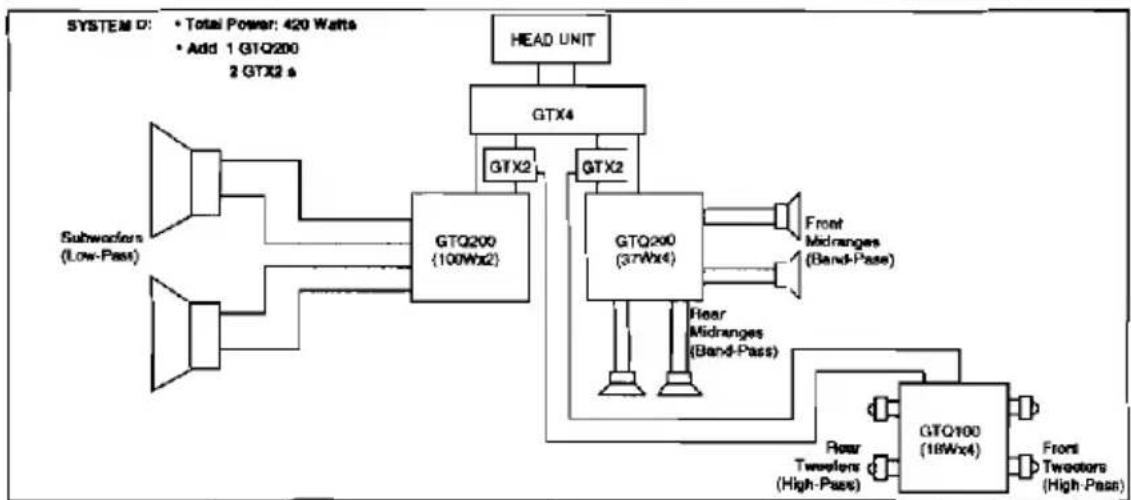
flowchart
graph TD
    A["Subworkers (Low-Pass)"] --> B["GTQ200 (100Wx2)"]
    C["Head Unit"] --> D["GTX4"]
    D --> E["GTX2"]
    E --> F["GTQ200 (37Wx4)"]
    F --> G["Front Midranges (Band-Pass)"]
    F --> H["Fear Midranges (Band-Pass)"]
    H --> I["GTQ100 (18Wx4)"]
    I --> J["Front Tweezers (High-Pass)"]
    B --> K["GTX2"]
    K --> L["GTQ200 (100Wx2)"]
    L --> M["Head Unit"]
    style A fill:#f9f,stroke:#333
    style C fill:#f9f,stroke:#333
    style D fill:#ccf,stroke:#333
    style E fill:#ccf,stroke:#333
    style F fill:#cfc,stroke:#333
    style H fill:#cfc,stroke:#333
    style I fill:#fcc,stroke:#333
    style J fill:#fcc,stroke:#333