58013 - Rototiller TORO - Free user manual and instructions
Find the device manual for free 58013 TORO in PDF.

| Product Type | Rototiller |
| Brand | Toro |
| Model | 58013 |
| Engine Type | Gasoline, 4-stroke, OHV |
| Displacement | 163 cc |
| Tilling Width | 16 inches |
| Tilling Depth | 6 inches (adjustable) |
| Number of Tines | 4 (forward rotating) |
| Wheel Size | 12 inches |
| Transmission | Gear drive with forward and reverse |
| Starting System | Recoil start with primer bulb |
| Weight | 90 lbs |
| Dimensions (L x W x H) | 36 x 20 x 38 inches |
| Fuel Tank Capacity | 0.5 gallons (unleaded gasoline) |
| Oil Capacity | 0.5 quarts (SAE 30 or 10W-30) |
| Handle Type | Adjustable, ergonomic with padded grip |
| Safety Features | Engine stop bar, rear shield, tine guard |
| Maintenance | Change oil every 25 hours; clean air filter regularly |
| Cleaning | Remove debris after each use; wash with mild soap and water |
| Spare Parts Availability | Genuine Toro parts available online and at dealers |
| Repairability | User-replaceable tines, belts, and spark plug |
Frequently Asked Questions - 58013 TORO
User questions about 58013 TORO
0 question about this device. Answer the ones you know or ask your own.
Ask a new question about this device
Download the instructions for your Rototiller in PDF format for free! Find your manual 58013 - TORO and take your electronic device back in hand. On this page are published all the documents necessary for the use of your device. 58013 by TORO.
USER MANUAL 58013 TORO
CAUTION: This tiller is engineered and tested to offer reasonably safe and effective service, provided it is operated in strict accordance with these instructions. FAILURE TO DO SO MAY RESULT IN PERSONAL INJURY.
TRAINING
- Never allow children to operate a tiller or adults to operate it without proper instruction
- Know the controls and how to stop quickly — READ THE OWNER'S MANUAL.
PREPARATION
- Handle gasoline with care - it is highly flammable
A. Use approved gasoline container
B Fill gas tank outdoors, never while engine is running. Wipe up spilled gasoline
C Replace gasoline cap securely
D. Open doors if engine is run in a garage — exhaust gases are extremely dangerous
- Keep children and pets a safe distance away at all times
- Inspect the area to be tilled Remove glass, wire, metal objects, large sticks, and stones
OPERATION
- Give complete and undivided attention to the job at hand.
- Personal injury may result from debris thrown by this machine. Therefore, always stay a safe distance away from tines.
- Maintain solid and secure footing at all times.
- Never place face in front of tines while tines are rotating
- Check before each use for loose fasteners or parts
11 Stop engine and disconnect spark plug lead wire before cleaning tines, removing obstacles, making adjustments or when leaving operating position.
12. Never place hands or feet under or into rotating parts or concealed areas. Keep hands and feet clearly away from tine elements, belts, pulleys etc., while engine is running
13 When striking a hidden object immediately place throttle in "STOP" position, disengage all controls, disconnect spark plug lead wire, and check for damage or loose parts. Repair damage at once.
14 Do not use tiller in wet soil
15 Wear substantial shoes while using tiller
16 Never work on tiller while engine is running
MAINTENANCE
17 keep engine free of debris buildup.
18 Follow maintenance instructions as outlined in this manual.
19. Have an authorized Toro Service Dealer inspect the tiller each year.
20. Disconnect spark plug wire before making any adjustment or repair.
21. Store gasoline in an approved red metal container in a cool, dry place.
22 Keep machine in good operating condition and keep safety devices in place.
23 Safety and performance levels can be assured only by the use of specified Toro replacement parts.
TABLE OF CONTENTS
| Page | Page | ||
| Safety Instructions | Front page | Adjusting Handle Height | 7 |
| Foreword | 2 | Maintenance | 8 |
| Loose Parts Chart | 2 | Lubrication | 8 |
| General Assembly Instructions | 3 | Servicing Air Cleaner | 8 |
| Preparation Before Starting | 4 | Changing Engine Oil | 8 |
| Filling With Oil | 4 | Engine Cooling | 8 |
| Filling With Gasoline | 4 | Changing Transmission Oil | 9 |
| Air Cleaner | 4 | Changing Tilling Speed | 9 |
| Know Your Controls | 5 | Adjusting Tiller Clutch | 9 |
| Operating Instructions | 5 | Throttle Control Adjustment | 9 |
| Starting | 5 | Spark Plug | 10 |
| Stopping And Emergency Stopping | 5 | Carburetor Adjustment | 10 |
| Transport Position (Depth Gauge Bar) | 5 | Engine Specifications | 10 |
| Depth Gauge Bar Use | 6 | Tune-up Specifications | 10 |
| Operating Tips | 6 | Off Season Storage | 10 |
| Tilling Pattern | 6 | Important Ordering Instructions | 11 |
| Tilling Depth | 6 | The Toro Promise | 11 |
| Changing Tilling Width | 7 |
FOREWORD
TO THE TORO OWNER...
Toro knows how important proper tilling equipment is for soil conditioning and Toro designers have, over the years, strived for and achieved the finest in tilling products. You, as a Toro owner, share the most advanced methods and machines available today. Give it the proper care, and it will repay you with precision service
The more you know about the operation and mechanics of your Toro tiller, the better job it will do for you. That's why it is important to read your Owner's Manual from cover to cover before attempting to operate the machine
Compare the illustrations to your tiller so as to familiarize yourself with locations of controls, lubrication points, and adjustment sites
Study the Safety Instructions thoroughly to insure proper functioning and to prevent injury to yourself and others
At times minor changes are made in Toro products to improve their efficiency. Should you notice a variation in your tiller that is not reflected in the Owner's Manual, see your Toro distributor or his authorized Toro Service Dealer (see yellow pages) for information and part numbers.
LOOSE PARTS CHART
| DESCRIPTION | QUANTITY |
| Cap screw 5/16 x 1-3/4" | 4 |
| Cap screw 3/8 x 2-1/4" | 2 |
| Lock nut | 2 |
| Shoulder spacer | 2 |
| Cap screw 3/8 x 1" | 4 |
| Lock nut | 4 |
| Washer | 1 |
| Cotter pin | 2 |
| Cable clip | 1 |
| Pulley cover | 1 |
| Owner's Manual | 1 |
IMPORTANT: Make sure your dealer has filled out the TORO Registration Card supplied with your machine, and that you have received your copy. This card validates the date of purchase, date of warranty, and will ensure proper post-sale service.

SAFETY
This Safety Alert symbol is intended to call your attention to a message concerning your personal safety. It means...
ATTENTION! BECOME ALERT! YOUR SAFETY IS INVOLVED!
Read and remember the message. This machine is as safe as good, practical design can make it. Keep the Operating and Safety Instructions in mind while using it.
Unpack your tiller with care to avoid damaging the unit or misplacing the loose parts. Carefully inspect the unpacked items to make certain damage has not occurred during shipment. Be sure to locate the loose parts bag containing hardware.
GENERAL ASSEMBLY INSTRUCTIONS
NOTE: Tillers with slasher tines are shipped with the outer tines reversed on the shaft to conserve space in the cartons. Reverse the sections and secure with the drilled pins and hairpin cotters. Install so the sharp edge of each tine enters the ground first when travelling forward
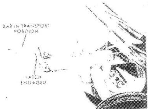
- Place the depth gauge bar in the transport position as shown in Fig. 1 and secure with the latch
rig.
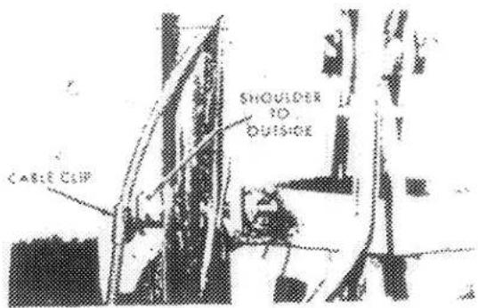
Fig. 4
- Install appropriate end of the clutch rod through the clutch lever and secure with a cotter pin. Place the other end of the rod through the slot in the bell crank and secure with a flat washer and cotter pin.
IMPORTANT: The front end of the clutch rod must be behind the flange on the reverse link.
- Position handle on the Tiller chassis and secure with four 3/8 x 1" capscrews and lock nuts.
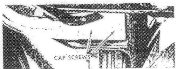
Fig. 2
- Install the throttle cover plate and clutch lever assembly on the handle with four 5/16 x 1-3/4" capscrews
x^2+y^2=r^2
- Slip the cable clip and a shoulder spacer onto a 3/88 x 2-174" capscrew and secure the right hand handle that support to the right hand handle as shown in Fig. 4. Note that the shoulder on the spacer must face to the outside. Bend the clip around the throttle control cable - do not pinch tight. Secure the left side in the same manner except there is no cable clip.
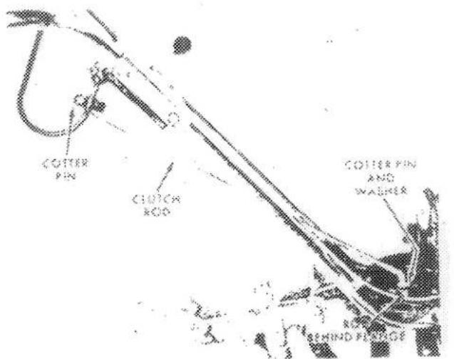
Fig. 5
6 Slide the pulley cover in position on the shoulder. Assets and span in place next to the engine
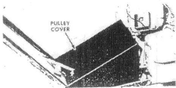
Fig. 6
PREPARATION BEFORE STARTING
The engine has been shipped from the factory without oil and gasoline. Therefore it is essential that the Preparation Before Starting instructions on this page be strictly followed.
FILLING WITH OIL
- Place Tiller on a level surface. This is very important. If the Tiller is tilted in one direction the oil level will be too low; if tilted in the other direction, the oil level will be too high. Make sure the area around the filler plug is clean, and remove the plug.
- Using a funnel, slowly pour a good grade of MS, SC, or SD classification SAE 10W-40 oil into the crankcase to the point of overflowing. The capacity of the crankcase is approximately 1-1/4 pints.
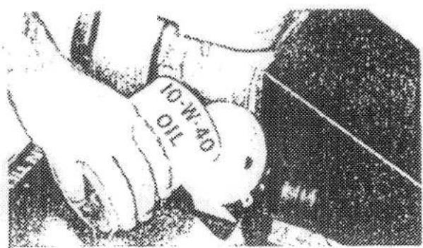
Fig. 7
- After the proper amount of oil has been added, replace the oil filler plug.
- Change oil after the first 5 hours of operation and check oil level after 5 operating hours or each time the Tiller is used
- After the first change, the oil should be changed every 25 hours of operation. (See Changing Engine Oil, page 8).
- Check transmission oil level, making sure that Tiller is level. If oil is not at the point of overflowing, add a good grade of No. 90 gear oil. Change transmission oil once a year. (See Changing Transmission Oil page 9.)
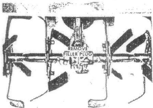
Fig. 8
FILLING WITH GASOLINE
Fill the gasoline tank with a fresh supply of the new automotive anti-pollution unleaded regular gasoline or regular gasoline
CAUTION! Handle gasoline with care - it is highly flammable. Do not add gasoline to your Tiller in an enclosed area. Fill gasoline tank outdoors and wipe up spilled gasoline. Do not add gasoline while the engine is hot or running. Keep gasoline and storage cans clean. Use an approved container. Do not smoke when adding gasoline. Keep the area around the tank cap free of debris.
The fuel tank capacity on the 3 H.P. Tiller is approximately two quarts, on the 4 and 5 H.P. Tillers, approximately three quarts
DO NOT MIX OIL WITH GASOLINE. DO NOT USE PREMIUM GASOLINE, WHITE STOVE GAS, OR GASOLINE ADDITIVES.
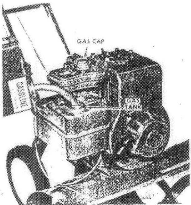
Remove air cleaner (See Servicing Air Cleaner, page 8), and make sure foam element is lightly oiled.
KNOW YOUR CONTROLS
To engage the clutch, push the lever forward until locked into position. To disengage, pull the lever back and allow it to fall into the neutral position. By exerting continuous downward pressure on the lever, the unit will be in reverse. This will aid in freeing tines of tangled weeds, getting rid of foreign objects that might be jammed against the Tiller, and for backing out of tight places.
The throttle control positions are clearly marked on the cover plate. See Operating Instructions.
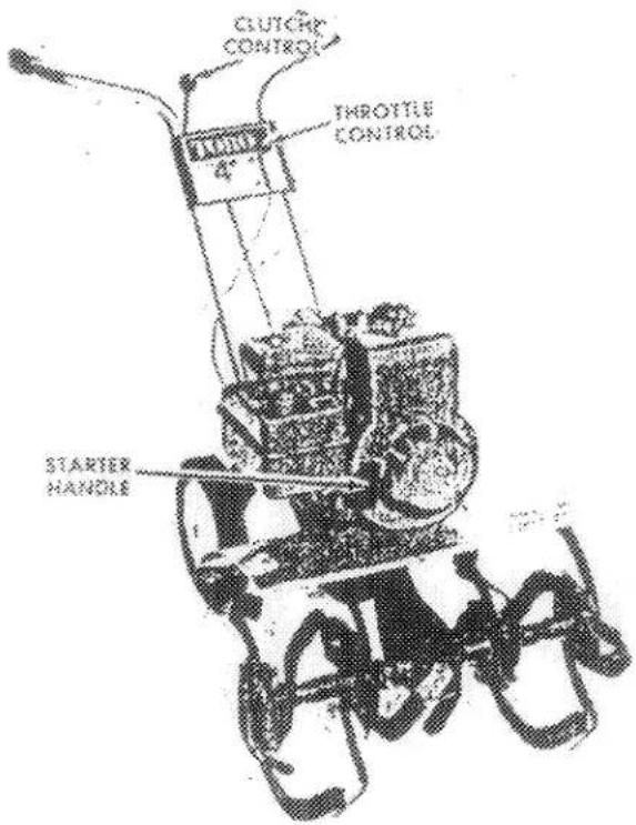
Fig. 10
OPERATING INSTRUCTIONS
STARTING
- Ensure that the spark plug lead wire is connected to the spark plug.
- Clutch MUST be disengaged.
- Push throttle control lever to CHOKE position.
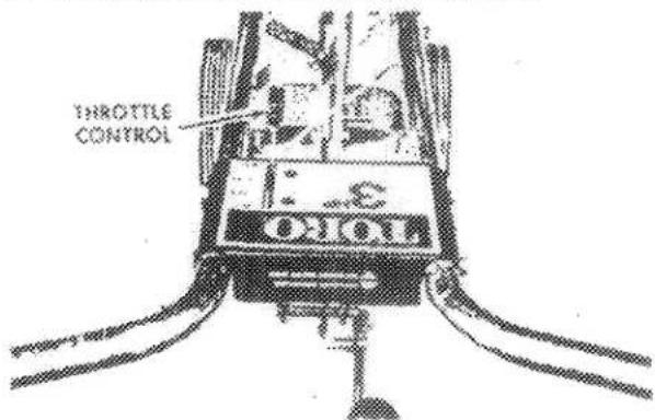
Fig. 97
- Pull recoil starter rope quickly. Keep a firm grip on the handle and return the rope slowly. DO NOT ALLOW IT TO SNAP BACK.
-
When engine starts, move throttle control level between FAST and IDLE positions.
-
If engine tends to die, move throttle lever to CHOKE position until engine begins to run smoothly
- Return nrottle lever between FAST and IDLE
STOPPING AND EMERGENCY STOPPING
To stop the engine, pull throttle control lever back to STOP position.
TRANSPORT POSITION (DEPTH GAUGE BAR)
For transporting the Tiller, swing the depth gauge bar forward between the wheels and secure with the latch as shown in Fig. 12.
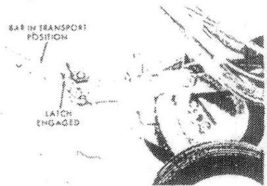
Fig. 12
OPERATING INSTRUCTIONS (CONTINUED)
DEPTH GAUGE BAR USE
When the depth gauge bar drags in the loosened soil, it holds the tiller back, keeping the tines digging to the proper depth. This saves the operator most of the effort of holding the tiller back while it is tilling soil.
When first breaking into untilled soil, hold tiller back manually and allow tiller to turn up hard soil. After enough soil has been loosened to allow depth gauge bar to drag in tilled soil, set bar to desired depth. Proper depth of the gauge bar depends on soil moisture, looseness, and how deep you want the tines to dig. The deeper the bar is set, the deeper the tines will dig. Therefore, depth of the bar should be determined each time the tiller is used. With a little experience, depth can be judged quickly. Proper depth is obtained when operator only has to guide the tiller.
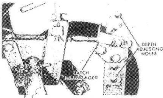
Fig. 13
OPERATING TIPS
Rotary tillage prepares garden soil for planting, in one or two operations. Your tiller will effectively do this job for you with a minimum of effort.
The time for using your tiller is governed by conditions of moisture and firmness of the soil. Soil conditions vary widely. It is best not to till the soil when it is too wet or too dry. When it is too wet, the tilled soil tends to ball up into lumps that are hard to work when they dry.
For spring break-up, or when breaking up new areas, set the unit for deep tilling.
Your tiller is not limited to garden usage. Use it to prepare flower beds and lawn areas for planting. You can operate it to dig as deeply or as lightly as you want. When you have dirt to dig or light grading to do, don't break your back with a pick and shovel. Let your tiller loosen the dirt for you.
As you become familiar with the tiller, you'll discover that it has many other uses.
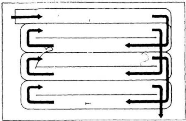
TILLING PATTERN
Where possible, we recommend tilling in a pattern similar to that shown in Fig. 14. Make the first pass, then skip space equal to the width of the Tiller, and make the return pass. Then, till the skipped area. Tilling in this pattern will enable you to maintain better control. If the passes were made side-by-side, the Tiller would tend to pull toward the tilled (soft) side.
flowchart
graph TD
    A["Top Channel"] --> B["Left Channel"]
    A --> C["Right Channel"]
    A --> D["Bottom Channel"]
    B --> E["Left Arrow"]
    C --> F["Right Arrow"]
    D --> G["Bottom Arrow"]
    style A fill:#f9f,stroke:#333
    style B fill:#ccf,stroke:#333
    style C fill:#cfc,stroke:#333
    style D fill:#fcc,stroke:#333
Fig. 14
TILLING DEPTH
The tilling depth may be adjusted by loosening the adjustment screw. This allows the notch on tiller drawbar to be adjusted to the shallow or deep setting shown on the side of the axle bracket. The shallow position is best for transport.
The axle has two slots for the notch on the tiller drawbar to position itself in. Be sure notch is in slot before tightening adjustment screw.
The roll pin in the axle can be used as a pointer to indicate shallow or deep setting of tiller.
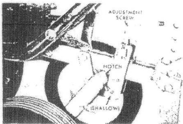
Fig. 15
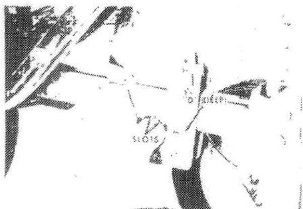
Fig. 16
OPERATING INSTRUCTIONS (CONTINUED)
The wheels may be tilted to the front or to the rear by loosening adjustment screw positioning wheels in desired position and retightening adjustment screw.
natural_image
Technical diagram of a mechanical device with labeled parts (no readable text or symbols)Fig. 17
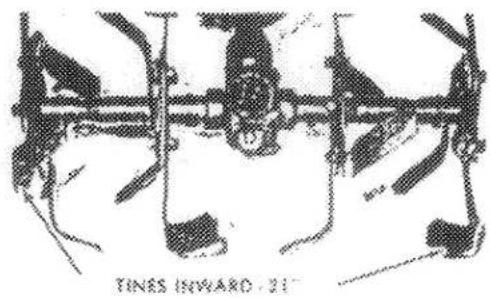
CHANGING TILLING WIDTH
The Tiller is shipped with all tines on the outer tine sections facing inward.
- If you wish additional tilling width, remove the two outer blades from each outer tine section
IMPORTANT: The tines are right and left hand, and must be switched from one end to the other, so the sharp edge will be forward.
- Place the two blades from the left hand section on the right section, with the blades curving outward, and the sharp side forward.
- Place the two blades from the right hand section on the left section, with the blades curving outward and the sharp side forward.
- Tighten the capscrews securely.
natural_image
Diagram of mechanical components with no visible text or symbolsFig. 18
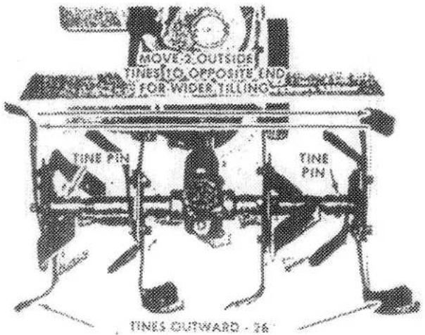
Fig. 19
5. When tilling under certain conditions, such as between rows, it may be desirable to remove one or both outer tine sections. Simply remove the cotter pin and tine pin to remove a section.
6. The following table shows the tilled widths you can obtain with various line arrangements
| TINE ARRANGEMENT | TILLED WIDTH | |
| Bolo | Slasher | |
| Two center sections only . . . . | 14" | 14" |
| Two center sections and one outside section only . . . . . | 17" | — |
| Center and both outside sections with tines on outer sections facing inward . . . . . | 21" | — |
| Center and both outside sections with two tines on each outer section facing outward . . . . . | 26" | 26" |
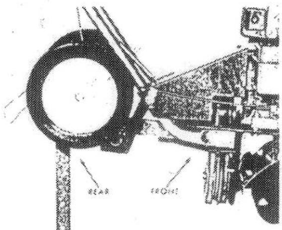
ADJUSTING HANDLE HEIGHT
The handle height may be adjusted to either of two positions to best suit the operator. Fig. 20 shows two mounting positions for the wheels. Moving the wheel bolts to the upper set of holes will lower the handle.
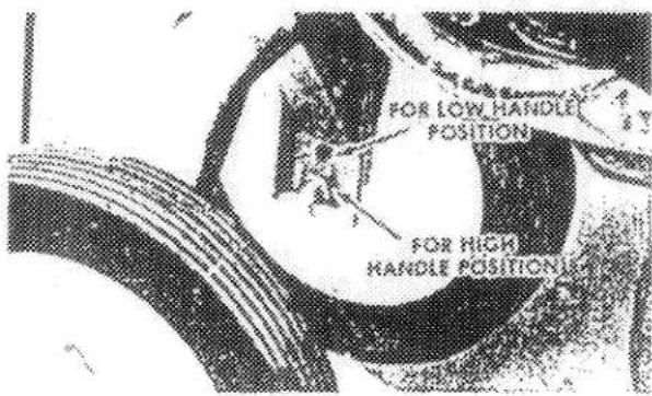
Fig. 20
MAINTENANCE
CAUTION: When performing any maintenance on your Tiller, disconnect the spark plug wire and secure it in the V-shaped notch in the engine shroud to prevent accidental contact with the spark plug.
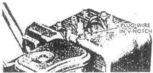
Fig. 21
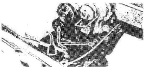
LUBRICATION
Keep Tiller properly lubricated.
- Apply a few drops of SAE 20 oil to all pivot points every 15 operating hours. Occasionally place a few drops of oil on the wheel bolts.
natural_image
Black-and-white photo of two people in a cockpit, one seated and one standing, with no visible text or symbols.Fig. 22
SERVICING AIR CLEANER
Your engine is equipped with a polyurethane type element in the air cleaner. Clean air cleaner and re-oil element every 25 hours of operation under normal conditions. Clean every few hours under extremely dusty conditions. To clean, proceed as follows:
- Remove screw and remove air cleaner carefully to prevent dirt from entering carburetor.
- Disassemble and clean air cleaner.
- Wash polyu:ethane element in kerosene or liquid detergent and water.
- Completely dry element by wrapping and squeezing in a cloth.
- Soak element with engine oil. Squeeze to distribute and remove excess oil.
- Reassemble parts and reassemble to carburetor.
IMPORTANT: Do not run engine with the air cleaner disassembled, or without the polyurethane element in place.
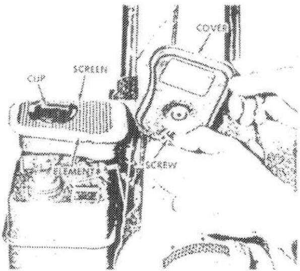
Fig 23
CHANGING ENGINE OIL
Change oil after the first 5 hours of operation and thereafter every 25 hours of operation as follows.
- Drain oil while the engine is warm. Dirt and sludge will be held in suspension and will drain with the oil
- Clean the area around the filler and drain plugs and remove the plugs
- Allow the oil to drain into a shallow pan. Be sure the oil drains completely
4 Replace drain plug and refill crankcase with fresh oil (See Filling With Oil, page 4)
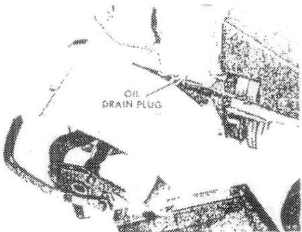
Fig. 24
ENGINE COOLING
KEEP THE ENGINE CLEAN. This is an air-cooled engine and clogging of the cooling system may cause serious damage. Keep the blower fins on the flywheel, blower screen, the cylinder and cylinder head free from dirt and foreign material
MAINTENANCE (CONTINUED)
CHANGING TRANSMISSION OIL
Change transmission oil once each year. Drain after Tiller has been in operation, oil will be warm and will drain easily
- Remove gasoline from tank to prevent spilling when unit is tipped to drain oil.
- Position Tiller on a flat level surface.
- Remove filler plug.
- Tip Tiller forward and allow oil to drain into a container. Be sure oil drains completely.
- Refill with a good grade of SAE 90 gear oil. Replace filler plug
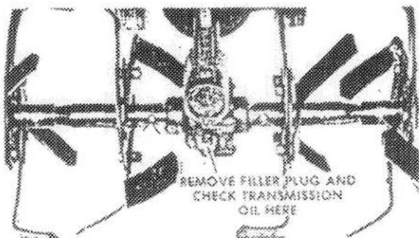
Fig. 20
CHANGING TILLING SPEED
Models 58114 & 58125 (4 H.P.). 58220 & 58231 (5 H.P.) only.
The Tiller is shipped with the belt in the fast position. To reduce the speed, first REMOVE THE SPARK PLUG LEAD WIRE and secure it in the V-shaped notch. (See Fig. 21). Remove the pulley cover, and move the large belt to the adjacent set of forward pulleys (small top pulley and large bottom pulley). Replace pulley cover DO NOT CHANGE BELTS WHILE THE ENGINE IS OPERATING.
When the belt is on the set of pulleys closest to the engine, the tines revolve less rapidly for better cultivation of small plants.
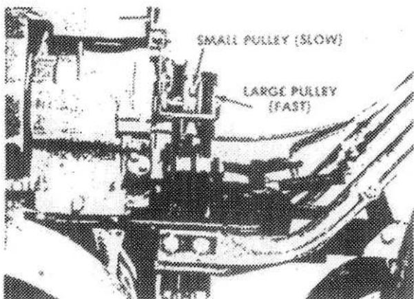
Fig.28
After some time, belt wear will occur, causing drive belt slippage, resulting in improper clutch operation. The spring in the clutch linkage allows considerable belt wear before an adjustment is necessary. To adjust, proceed as follows
- Remove the pulley cover.
- Three flat washers have been assembled on the engine mounting bolts at the factory.
- Remove the engine mounting bolts and move one of the washers on each bolt from under the Tiller casting to the top of the casting (between the casting and the plant shield). Replace the engine mounting bolts.
- If one washer does not give sufficient belt adjustment, use 2 or 3 washers on each bolt.
IMPORTANT: Use the same number of washers on each engine mounting bolt. If this instruction is not followed, the engine base or Tiller casting may break.
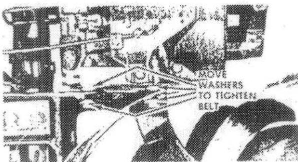
Fig. 27
THROTTLE CONTROL ADJUSTMENT
Use the following steps to adjust the throttle control cable at the carburetor:
- Move the throttle control lever on the control panel as far forward as possible (CHOKE position).
- Loosen throttle control cable clamp screw (on carburetor) so cable can move freely.
- Move control casing forward as far as possible on 4 & 5 H.P. models; on 3 H.P. model, move casing up
- Secure cable clamp and casing with screw.
- Start engine. Make sure engine will stop when throttle control is moved to STOP position. Readjust cable casing as necessary.
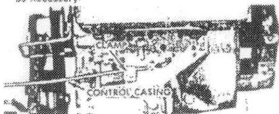
Fig. 28
MAINTENANCE (CONTINUED)
SPARK PLUG
Use spark plug of the type specified below for replacement. Clean and reset the gap at 030 inch every 25 hours of operation. Apply light coating of graphite grease on threads before replacing plug. If plug is pitted or cannot be cleaned easily, install a new plug.

natural_image
Illustration of a person wearing a headlamp, with no visible text or symbolsFig. 29
CARBURETOR ADJUSTMENT
Minor carburetor adjustment may be required to compensate for differences in fuel, temperature, altitude and load. Adjust carburetor with tank half full of regular grade gasoline
Initial Adjustment: Close needle valve (turn clockwise). Do not force valve against seat or both seat and valve could be damaged. Then open the valve 1-1/2 turns (counterclockwise). This initial adjustment will permit the engine to be started and warmed up before making the final adjustment.
Final Adjustment With engine running at normal operating speed (approximately 3000 RPM without load) close the needle valve (turn clockwise) until engine starts to lose speed (lean mixture). Then slowly open needle valve (turn counterclockwise), past the point of smoothest operation, until engine just begins to run evenly. This mixture should be rich enough for best performance under load.
Hold throttle in idling position. Turn idle adjusting screw until fast idle is obtained (1750 RPM).
Test the engine under full load. If engine tends to stall or die out, it usually indicates that the mixture is slightly lean and it may be necessary to open the needle valve slightly to provide a richer mixture. This richer mixture may cause a slight unevenness in idling.
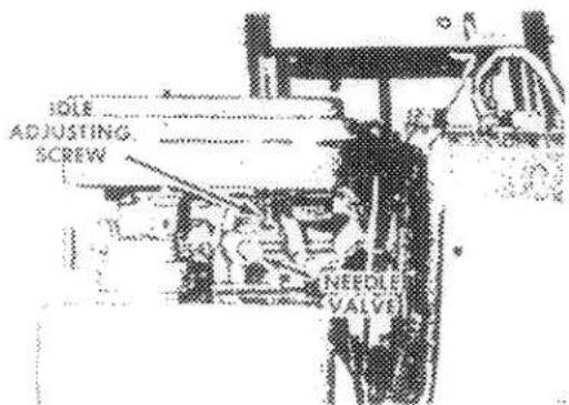
Fig. 30
ENGINE SPECIFICATIONS
| 3 H.P. | 4 H.P. | 5 H.P. | |
| Bore | 2 3/8" | 2 1/2" | 2 9/16" |
| Stroke | 1 3/4" | 2 1/8" | 2 7/16" |
| Displacement (cu. in.) | 7 75 | 10 43 | 12 57 |
| Horsepower at 3600 RPM | 30 | 40 | 50 |
| Torque (ft -lbs) | 4 39 at 3400 RPM | 5 93 at 3050 RPM | 7 66 at 3000 RPM |
TUNE-UP SPECIFICATIONS
| Spark Plug Type | A C | Autolite | Champion | Spark Plug Gap | 030" |
| Short Plug | CS-45 | A7N | CJ-8 | Ignition Point Gap | 020" |
| Long Plug | GC-46 | A71 (3 HP) | J-8 | Intake Valve Clearance | 005-007" |
| A7Q (4 & 5 HP) | Exhaust Valve Clearance | 009-011" |
OFF SEASON STORAGE
In the event tiller is to be stored for any length of time (30 days or more); or at the end of the tilling season, prepare as follows:
- Drain fuel tank completely to prevent gum deposits from forming in the carburetor, fuel line, and gas tank. Run the engine until gas in carburetor has been expended.
CAUTION: Drain gasoline into container outdoors away from fire or flame.
-
Drain crankcase oil while engine is warm. Refill with fresh oil.
-
Remove spark plug, pour two or three tablespoons of SAE 10-W-40 oil into cylinder. Crank engine slowly to distribute oil. Replace spark plug.
-
Clean dirt and chaff from cylinder, cylinder head fins, and blower housing.
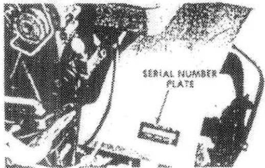
IMPORTANT ORDERING INSTRUCTIONS
Repair parts are available from your TORO dealer.
To insure getting correct parts without delay, please furnish the following information:
- Model and serial number of your tiller as shown on the name plate.
- Part number, description and quantity of each part required.
- Do not order by reference number; use part number only.
For your own convenience, we suggest you write in the numbers of your machine in the space provided below.
The illustration below shows the location of the serial number plate.
THE TORO PROMISE
It is Toro's policy to design and produce TORO products to provide our customers with a high level of performance and durability in normal operation. Our products, however, are produced in high volume, and it is inevitable that occasionally a unit will reach a customer with a defect in materials or workmanship which causes the unit to fall below the normal high
level of TORO performance. Invariably, such a defect will be noticed in a residential product within one year after purchase. Recognizing this possibility, Toro has established a simple guarantee policy and procedure that is intended to assure customer satisfaction. This guarantee statement is as follows:
The Turn Promise
A Full One Year Warranty
The Toro Company promises to repair any TORO Product if defective in materials or workmanship. The following time periods from the date of purchase apply:
Residential Product 1 year
Residential Products Used Commercially .. 45 days
The costs of parts and labor are included, but the customer pays the transportation costs. Just return any residential product to an Authorized TORO Service Dealer or TORO Distributor.
The image contains no legible text or symbols. The OCR result "5" is a hallucination and does not correspond to any content in the source image. Therefore, the correct OCR output is an empty string.
Should the customer feel that a product is defective and wish to rely on The Toro Promise, the following procedure is recommended:
- Contact any Authorized TORO Servide Dealer or Distributor, but preferably the dealer or distributor from whom you purchased the product.
- He will instruct you to either return the product to him, or tell you the name and address of your nearest Authorized TORO Service Dealer or Distributor if the product is to be returned to such a dealer or distributor.
- Bring the product and your original sales slip, or
other evidence of purchase date, to the service dealer or distributor.
- The servicing dealer or distributor will inspect the unit, advise you whether the product is defective and, if so, make all repairs necessary to correct the defect without extra charge to the customer.
If for any reason the customer is dissatisfied with the dealer's or distributor's analysis of the defect or the service he performs, he can contact us. Write:
TORO "Customer Care" Department 8111 Lyndale Avenue South
Bloomington, Minnesota 55420