51630 - Brush cutter TORO - Free user manual and instructions
Find the device manual for free 51630 TORO in PDF.

| Product Type | Brush Cutter |
| Brand | Toro |
| Model | 51630 |
| Engine Type | 2-Stroke Gasoline |
| Displacement | 25 cc |
| Fuel Tank Capacity | 0.5 L |
| Cutting Width | 410 mm (16 in) |
| Cutting Head | Tap & Go Bump Feed |
| Line Diameter | 2.4 mm |
| Weight (without fuel) | 5.4 kg (12 lb) |
| Overall Length | 1.8 m (71 in) |
| Shaft Type | Straight, Steel |
| Handle Type | Loop Handle with Anti-Vibration |
| Starter Type | Recoil Start |
| Primary Use | Trimming grass and weeds |
| Maintenance Schedule | Every 10 hours: clean air filter; every 25 hours: replace spark plug |
| Safety Features | Throttle lockout, blade guard, shoulder strap |
| Spare Parts Availability | Spark plug, air filter, fuel filter, trimmer line, cutting head |
Frequently Asked Questions - 51630 TORO
User questions about 51630 TORO
0 question about this device. Answer the ones you know or ask your own.
Ask a new question about this device
Download the instructions for your Brush cutter in PDF format for free! Find your manual 51630 - TORO and take your electronic device back in hand. On this page are published all the documents necessary for the use of your device. 51630 by TORO.
USER MANUAL 51630 TORO
Table of Contents – Page 1 of 1
FOREWORD
GENERAL INFORMATION
MAINTENANCE PROCEDURES
AIR CLEANER MAINTENANCE
EXHAUST SYSTEM MAINTENANCE
FLEXIBLE DRIVE SHAFT MAINTENANCE
CARBURETOR ADJUSTMENTS -- MODEL TC-1 500 WITH TILLOTSON
CARBURETOR ADJUSTMENT -- MODELS TC-300, TC-400 WITH WALBRO
TROUBLESHOOTING AND TEST PROCEDURES
DISASSEMBLY, REPAIR, REASSEMBLY INSTRUCTIONS
The Toro Company — 1982
MINNEAPOLIS, MN 55420 — U.S.A.
Form 492-0266
FOREWORD
This Maintenance and Repair Guide will provide you with complete information necessary to accomplish the maintenance and repair of gasoline-powered flexible line trimmers powered by the new line of the lightweight two-cycle engines manufactured by The Toro Company.
The number of repair procedures for this line of engines has been limited for simplicity and economy. The repairs are easy to accomplish, even for operators or mechanics who have limited experience in the repair of small two-cycle engines.
Should you require additional information concerning these trimmers, we urge you to write to us. Address inquiries to:
The Toro Company
8111 Lyndale Avenue South
Minneapolis, MN 55420
Attn: Service Department
TABLE OF CONTENTS
PAGE
General Information 1-3
Two-Cycle Engine — Theory of Operation 1
Engine Operation 1
Engine Specifications 3
Engine Torque Specifications 3
Maintenance Procedures 4-7
Air Cleaner Maintenance 4
Exhaust System Maintenance 4
Flexible Drive Shaft Maintenance 5
Carburetor Adjustments; Model TC-1500 (Tillotson Carburetor) 5-6
Carburetor Adjustments; Models TC-300 & TC-400 (Walbro Carburetor) 6-7
Troubleshooting and Test Procedures....7-9
Preliminary Checks: 7
Testing Cylinder Compression 7
Compression Test Procedure 7
Checking For Spark 8
Checking Fuel Tank Venting 8
Engine Troubleshooting Chart 9
Checking Fuel Tank 8
Checking the Stop Switch 8
Disassembly, Repair, Reassembly Instructions 10-18
Trimmer Engine Removal, Disassembly, Replacement 10
Starter Rope Replacement.... 12
Starter Assembly Replacement 12
Walbro Carburetor Operation 13
Walbro Carburetor Servicing 14
Cutter Head Troubleshooting Chart....16
Clutch Repair 17
Automatic Line Feed Repair 18
GENERAL INFORMATION
Two-Cycle Engine — Theory of Operation
Two-cycle engines are used on TORO Trimmers because of their:
- Light weight.
- Excellent power-to-weight ratio
- Ability to operate in any position
- Easy maintenance
- Simple construction
The TORO Two-Cycle Engine used on the TC-1500, TC-300 and TC-400 Trimmers is a third-port, loop-scavenged design. This design name describes the path of the fuel/air mixture into the crankcase and combustion chamber, and the exhausting of spent gases (Fig. 1).
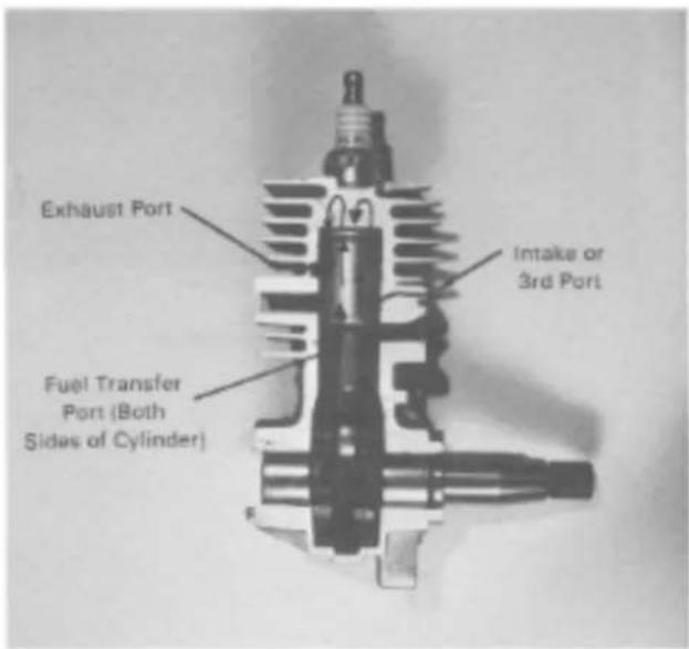
Figure 1
In a loop-scavenged engine with a third-port, the flow of the fuel/air mixture can be described as follows: (See Fig. 1).
- The fresh fuel/air mixture enters the crankcase through the third-port on the side of the cylinder. The oil in the fuel/air mixture lubricates the moving parts within the crankcase.
- The fuel/air mixture is transported through the fuel transfer ports to the combustion chamber where it is compressed, ignited, and then expelled from the engine through the exhaust port.
Engine Operation
The piston closes all engine ports as it moves toward the combustion chamber (Fig. 2). The moving piston creates high pressure in the combustion chamber and partial vacuum in the crankcase.
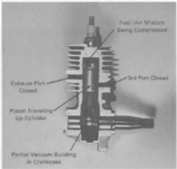
Figure 2 Compression Stroke
At a point slightly before top dead center (BTDC) of the piston travel, the spark from the plug ignites the fuel air mixture (Fig. 3). Also, at this time, the third-port opens allowing the fresh fuel/air mixture to rush into the crankcase to equalize the partial vacuum.
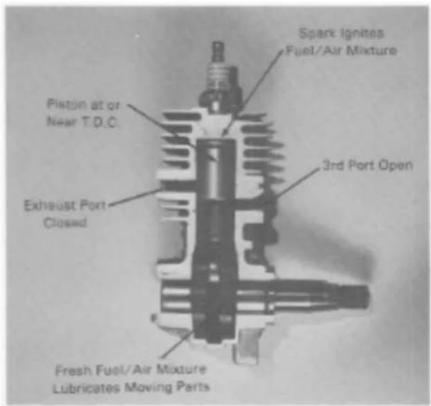
Figure 3 Ignition
GENERAL INFORMATION
The expanding gases from the burning fuel in the combustion chamber force the piston down the cylinder, closing the third-port and increasing the pressure in the crankcase. At a point approaching the bottom of the stroke, the exhaust port opens and the burnt gases begin to be expelled from the combustion chamber (Fig. 4).
At a point of piston travel slightly before bottom dead center (BBDC) the fuel transfer ports, on the sides of the cylinder walls, are uncovered and the compressed fuel/air mixture in the crankcase is allowed to enter the combustion chamber where they help expel the burnt gases and charge the chamber for the following piston stroke (Fig. 5).
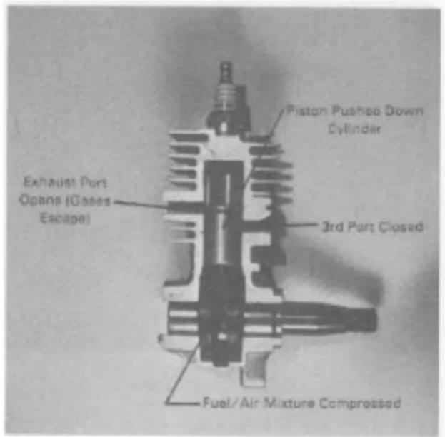
Figure 4 Power/Exhaust
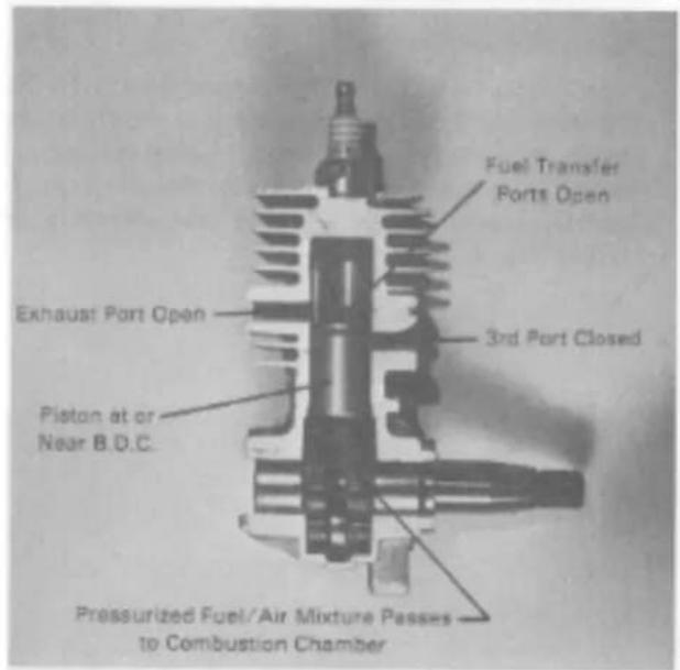
Figure 5 Exhaust/Fuel transfer
ENGINE SPECIFICATIONS
| TC 1500(Model 51630) | TC 300(Model 51603) | TC 400(Model 51604) | ||
| ENGINE: | ||||
| Type | TORO-built, air-cooled, two-cycle, single cylinder gasoline engine | |||
| Rotation | viewed from output end | Counter-clockwise | ||
| Displacement | cc (cu. in.) | 13.8 cc (.84 cu. in.) | 20.9 cc (1.28 cu. in.) | |
| Bore | mm (in.) | 26.0mm (1.02 in.) | 32mm (1.26 in.) | |
| Stroke | mm (in.) | 26.0mm (1.02 in.) | 26mm (1.02 in). | |
| Compression ratio | 7:1 | |||
| Operating speed | full line extension | 7400-9000 RPM | 6500-7500 RPM | |
| Idling speed | full line extension | 3000-4500 RPM | 3500 RPM Max. | |
| Cranking pressure | 689 kPa (100 lbs.) psi minimum | |||
| FUEL: | ||||
| Fuel to oil | gasoline:oil | 32:1 | ||
| Mixture | ||||
| Gasoline | leaded or unleaded regular | |||
| Oil | Genuine TORO Two-Cycle Oil or other high quality two-cycle oil, BIA approved | |||
| Fuel tank capacity liters (U.S. fl. oz.) | .40 L (13.5 oz.) | |||
| CARBURETOR: | ||||
| Type | Tillotson Model SP-1A with self contained fuel pump, accelerator pump, and filter screen | Walbro Wa-120 series with self contained fuel pump and filter screen | ||
| Adjustment | initial | Factory adjusted and test run. Adjusting Procedures pp. 5-6 | Factory adjusted and test run. Adjusting Procedures pp. 6-7 | |
| IGNITION SYSTEM: | Solid state, capacitive discharge ignition (CDI) | |||
| Ignition timing | BTDC | 22 degrees BTDC | ||
| Ignition timing | piston position, mm (in.) | 1.29-1.67mm (.051-066 in.) BTDC | ||
| Magneto air gap | mm (in.) | .20-.30 mm (.008-.012 in.) | ||
| Spark plug | recommended (alternates) | NGK-BM6A (Champion CJ-8, AC CS-45) | ||
| Spark plug gap | mm (in.) | .5-.6mm (.020-.024 in.) | ||
| AIR CLEANER: | Foam & felt filter elements | |||
| SPARK ARRESTING MUFFLER: | optional | Standard on certain models | ||
| STARTER: | ||||
| Type | Spring rewind, recoil starter | |||
| Starter rope diameter x length mm (in.) | #4 Diamond Braid 3.18mm (.125 in.) x 1.02m (40 in.) | |||
| Starter pre-wind | Refer to recoil start repair instructions, p. 12. | |||
| DRIVE SYSTEM: | Direct drive— 14 inch diameter flexible shaft to cutting head | 14 in. flexible shaft;centrifugal clutch at the cutting head. | ||
ENGINE TORQUE SPECIFICATIONS
| FASTENER LOCATION | QTY. | TORQUE Kg-cm/Kg-m | TORQUE in.-Ibs/ft.-Ibs. |
| Lower Backing Plate Screws | 3 | 35-41 Kg-cm | 30-45 in.-Ibs. |
| Upper Backing Plate Screws | 2 | 23-35 Kg-cm | 20-30 in.-Ibs. |
| Ignition Coil Screws | 2 | 29-40 Kg-cm | 25-35 in.-Ibs. |
| Cooling Shroud Screws | 3 | 12-23 Kg-cm | 10-20 in.-Ibs. |
| Carburetor Mounting Screws | 2 | 17-29 Kg-cm (plastic), 40-46 Kg-cm (metal) | 15-20 in.-Ibs. (plastic), 35-40 in.-Ibs. (metal) |
| Heat Shield Tab to Cylinder Screw | 1 | 35-46 Kg-cm | 30-40 in.-Ibs. |
| Heat Shield Tab Screw | 1 | 17-29 Kg-cm | 15-25 in.-Ibs. |
| Muffler Mounting Screws | 2 | 29-40 Kg-cm | 25-35 in.-Ibs. |
| Muffler Outlet Plate Screws | 2 | 23-35 Kg-cm | 20-30 in.-Ibs. |
| Flywheel Nut | 1 | 2.8-3.2 Kg-m | 20-23 ft.-Ibs. |
| Sparkplug | 1 | 1.9-2.4 Kg-m | 14-17 ft.-Ibs. |
NOTE: Metric Torque Conversions: inch-pounds X 1.152 = kilogram-centimeters foot-pounds X .1383 = kilogram-meters
MAINTENANCE PROCEDURES
AIR CLEANER MAINTENANCE
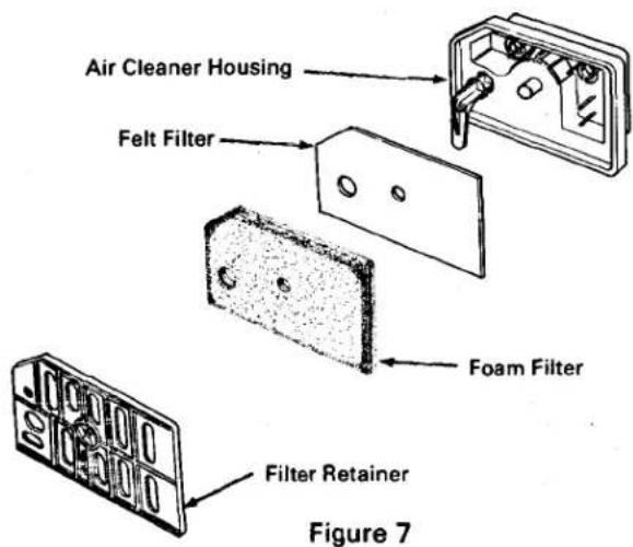
Check and clean the foam air cleaner element every eight operating hours, and the felt air cleaner once a season.
- Remove the air cleaner cover by pressing up on the bottom of the cover to release the lower mounting tab and pressing in on front of the cover to release the upper tab. DO NOT FORCE.
- Carefully remove the filter clip or filter retainer. Remove the foam filter and felt filter (Figures 6 and 7).
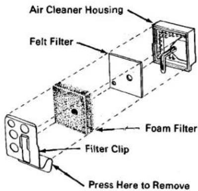
Figure 6
- Wash the foam filter in a soap and water solution and dry thoroughly. If the filter shows any sign of damage or deterioration, replace it.
-
Saturate the foam filter with one teaspoon (5 ml) SAE 30 oil. Squeeze the filter to distribute the oil evenly and to remove excess oil. A damp element is necessary to ensure proper functioning of the air cleaner.
-
Inspect the felt filter. If it is dirty, wash it in clean solvent and air dry it. If the filter shows any sign of damage it must be replaced.
- Reinstall the felt filter, foam filter, and filter clip or retainer in the air cleaner housing (Figures 6 and 7).
IMPORTANT: Make sure the peg in the air cleaner housing fits through the small hole in the felt filter. Both filters must cover the opening in the air cleaner housing.
- Reinstall the air cleaner cover by pressing the cover in, and up, behind the choke lever and then press the lower mounting tab into the hole in the engine housing. DO NOT FORCE.
EXHAUST SYSTEM MAINTENANCE
NOTE: Some states require that a spark arrester be attached to the muffler if the trimmer is to be used in forested areas, or on other public lands. Be sure to check your local state laws before using your gasoline powered trimmer.
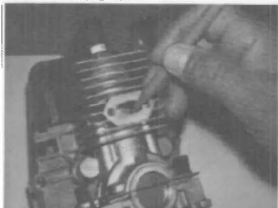
An important part of the maintenance procedure for all two-cycle engines is the cleaning or decarboning of the exhaust system. This is done to assure the unobstructed flow of exhaust gases and particles from the combustion chamber. A severely carboned muffler, spark arrester screen, and/or exhaust port will cause poor starting and low power output of the trimmer engine.
- Remove the muffler shield, screen, muffler and exhaust gasket.
- Soak the screen in solvent and remove the carbon build-up with a wire brush, or replace the screen.
- Clean the muffler baffle holes inside the muffler with a screwdriver.
- Check the cylinder exhaust port. If necessary, remove the carbon deposits from the port using a wooden stick (Fig. 8).
natural_image
Close-up of hands installing or adjusting a mechanical component (no visible text or symbols)Figure 8
MAINTENANCE PROCEDURES
IMPORTANT: WHEN REMOVING CARBON DEPOSITS, CLOSE THE PORT WITH THE PISTON TO PREVENT LOOSE CARBON DEPOSITS FROM FALLING INTO THE CYLINDER. TAKE CARE NOT TO SCRATCH THE PISTON. DO NOT USE A METAL TOOL SUCH AS A SCREWDRIVER.
- Reassemble the muffler components. Use a fresh exhaust gasket.
FLEXIBLE DRIVE SHAFT MAINTENANCE
The flexible drive shaft has been lubricated at the factory. After approximately every 40 hours of operation, the shaft should be removed from its housing and its entire surface coated with a No. 2 general purpose, lithium-base grease. To remove the shaft, loosen the lower handle and slide it toward the engine assembly to expose the clamp. Loosen the clamp and separate the upper and lower tube assemblies. The shaft will then be able to be pulled from the lower tube (Fig. 9).
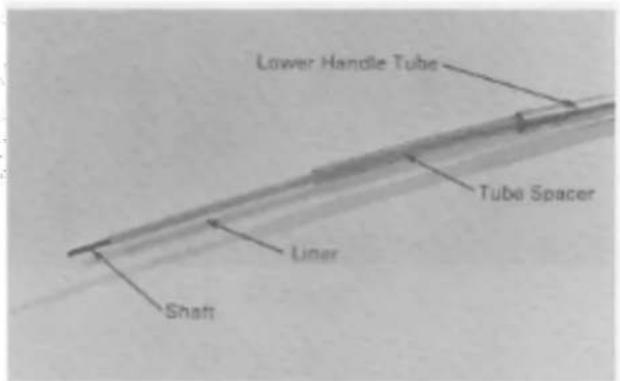
Figure 9
CARBURETOR ADJUSTMENTS — MODEL TC-1500 WITH TILLOTSON CARBURETOR
The carburetor has been adjusted at the factory, but an adjustment may be required to compensate for differences in fuel, temperature and altitude. The Tillotson carburetor used on the TC-1500 is not serviceable. If carburetion difficulties cannot be corrected by adjustment, the carburetor must be replaced.
IMPORTANT: The correct amount of line must be fed from the trimmer spool before adjusting the carburetor to ensure that the engine is adjusted for operation while under load.
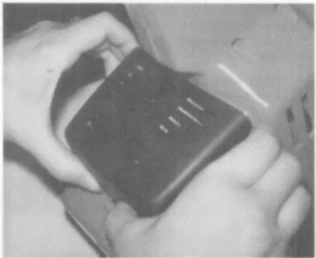
- Remove air cleaner cover by pressing up on bottom of cover to release lower mounting tab and pressing in on front of cover to release upper tab. DO NOT FORCE (Fig. 10).
natural_image
Close-up of hands holding a black electronic device (no visible text or symbols)Figure 10
CAUTION: THE ENGINE MUST BE RUNNING SO FINAL ADJUSTMENTS OF THE CARBURETOR CAN BE PERFORMED. TO GUARD AGAINST POSSIBLE PERSONAL INJURY, KEEP HANDS, FEET AND FACE AWAY FROM MOVING PARTS.
- Start the engine and let it warm up for approximately 3-5 minutes. Do not adjust the carburetor when the engine is cold. Be sure to perform the carburetor adjustments while in an area that is close to the average outdoor temperature at which the trimmer will be used.
CAUTION: DO NOT RUN THE TRIMMER INDOORS WITHOUT ADEQUATE VENTILA-TION. EXHAUST FUMES ARE POISONOUS AND COULD BE DEADLY IF INHALED.
NOTE: If the engine will not start or if the reference setting is lost, set both screws so the arrows point to "5½". Low number settings are lean. High number settings are rich. (Fig. 11).
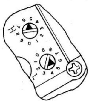
Figure 11
MAINTENANCE PROCEDURES
- Adjust Idle First: With engine idling, rotate the Low Speed Screw (L) for the leanest fuel mixture that allows stable idle, and acceleration without hesitation.
-
If necessary, idle speed can be increased by turning the idle stop screw clockwise (Fig. 12).
-
Low Speed Screw (L) (Fig. 13) — Close the screw by gently rotating it clockwise until a light seating resistance is felt. Next, rotate the screw 1 14 - 1 12 turns counterclockwise.
- Idle Screw (Fig. 13) — Close the screw by rotating it clockwise until the screw contacts the throttle lever. After contact is made, continue turning screw 1 12 - 2 12 additional turns.
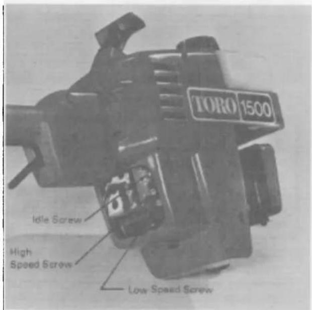
Figure 12
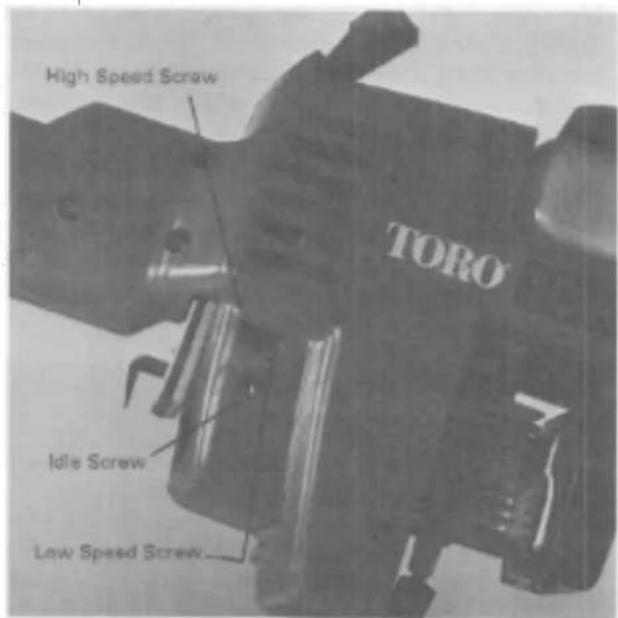
Figure 13
- Hold the throttle trigger at the maximum speed position and adjust the High Speed Screw (H) for maximum engine speed.
- Recheck the idle adjustment.
CARBURETOR ADJUSTMENT — MODELS TC-300, TC-400 WITH WALBRO CARBURETOR
IMPORTANT: Do not close the carburetor adjusting screws too tightly as damage to the screws and seats may result. Also, the correct amount of line must be fed from the trimmer spool before adjusting the carburetor to ensure that the engine is adjusted for operation while under load.
- High Speed Screw (H) (Fig. 13) — Close the screw by gently rotating it clockwise until a light seating resistance is felt. Next, rotate the screw one turn counterclockwise.
NOTE: Although these settings are approximate, the engine should be able to be started. Further adjustments of the carburetor may be necessary to obtain the best performance for your area. Steps 4-6 should be followed to fine tune the carburetor. When making these adjustments, turn the screws 18 of a turn at a time and wait for the engine to respond to the change.
A CAUTION: THE ENGINE MUST BE RUNNING SO FINAL ADJUSTMENTS OF THE CARBURETOR CAN BE PERFORMED. TO GUARD AGAINST POSSIBLE PERSONAL INJURY, KEEP HANDS, FEET, AND FACE AWAY FROM CONCEALED, MOVING, OR ROTATING PARTS.
MAINTENANCE PROCEDURES
- Start the engine and let it warm up for approximately 3-5 minutes. Do not adjust the carburetor when the engine is cold. The adjustments should be made at the temperatures that the trimmer will be used. Allow the engine to idle. If necessary, re-adjust the idle speed to keep the engine from stalling (3000-3500 RPM on the TC400, 3000-4500 on the TC300)
A CAUTION: DO NOT RUN THE TRIMMER INDOORS WITHOUT ADEQUATE VENTILA-TION. EXHAUST FUMES ARE POISONOUS AND COULD BE DEADLY IF INHALED.
- With the engine idling, slowly turn the low speed screw clockwise and note the position at which the engine begins to slow down. Now turn the screw counterclockwise and again note the position when the engine speed is reduced. Set the screw at a point midway between these two positions.
- Hold the throttle wide open and follow the same procedure to set the high speed screw.
- Re-check the idle adjustment.
- Install the air cleaner cover.
TROUBLESHOOTING AND TEST PROCEDURES
Generally, all gasoline-powered products require some form of service or repair during their lifetime. The amount of time and expense involved in repairing a product can be greatly impacted by the amount of time required to initially determine the cause of the difficulty. Therefore, it is recommended to make these preliminary checks before proceeding to secondary troubleshooting procedures.
Preliminary Checks
- Check for ignition:
a. Check the start/stop switch position -
Check the spark plug: (refer to specifications. page 3)
a. To ensure the correct type
b. For damage to the insulator
c. For excessive carbon or burnt electrodes
d. For the correct gap
e. Check for spark (refer to page 8) -
Check the fuel supply:
a. Check the choke position
b. Check the condition of the fuel, for freshness, cleanliness, and proper mixture
- Check the air cleaner: (refer to page 4)
a. For loose or damaged mounting screws
b. For dirty filter elements
c. For excessive oil in the foam element
- Check cylinder compression (refer to page 7)
Testing Cylinder Compression
A compression test of the engine can provide vital information on the general condition of the working
parts within the engine. This test will indicate a worn cylinder, piston, or ring and generally determine whether the engine is sound or if it should be replaced.
Compression Test Procedure
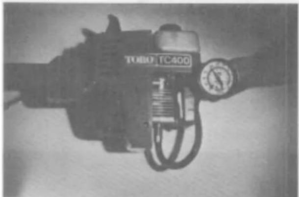
- Install the compression gauge into the spark plug hole. IMPORTANT: Be certain that no more than a 12 " of the gauge is threaded into the cylinder as damage to the piston may result (Fig. 14).
natural_image
Black-and-white photo of a TOBO TC400 industrial device with attached pressure gauge (no visible text or symbols on body)Figure 14 Compression testing
- Pull the starter rope several times to obtain the highest possible compression reading.
- If the compression reading is below 100 psi (689 kPa), cylinder, piston, or ring damage should be suspected. If so damaged, a new engine short-block should be installed.
TROUBLESHOOTING AND TEST PROCEDURES
Checking for Spark
- Pull off the spark plug cap and remove the spark plug.
- Inspect the spark plug for wear, carbon deposits and damage. Replace the plug if damaged, burnt or fouled.
- Check for the correct spark plug gap and adjust if necessary to .020-.024 in (.5-.6 mm) by bending outer electrode.
NOTE: Do not pry against inner electrode. This could crack the insulator.
- Attach a spark or ignition tester as shown in Figures 15 or 16.
- While maintaining the plug in this position, pull the starter rope and observe for spark.

CAUTION: DO NOT TEST FOR SPARK ERE GASOLINE HAS BEEN SPILLED OR LAMMABLE VAPORS MAY EXIST. A FIRE OLD RESULT.
NOTE: The spark may be difficult to see in daylight or other brightly illuminated areas.
- If no spark is seen, refer to the troubleshooting chart on page 9.
natural_image
Close-up of an electric motor with visible cooling fins and mounting brackets (no text or symbols)Figure 15
Spark tester
Toro P/N 41-7890
natural_image
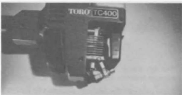
Close-up of a mechanical component labeled 'TORO TC400' (no other visible text or symbols)Figure 16
Alternate type spark tester
Checking Fuel Tank Venting
The fuel tank cap vent allows air into the tank as fuel is consumed. If this vent is blocked with dust or dirt, the engine will eventually stall.
- Remove the fuel tank cap and inspect the vent. If the cap is contaminated with dirt particles, the vent may need to be replaced.
- The cap can be disassembled by prying up the insert with a flat screwdriver. Care should be used to prevent damage to the insert and the valve (Fig 17). Cap
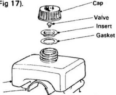
Figure 17
- Remove the valve, squeeze the valve to close it, release it, and hold it up to a light. No light should be visible through the valve. If light can be seen, the valve should be cleaned or replaced.
- With the insert removed, hold the cap up to a light. Light should be visible through a small hole at the center of the cap. If no light can be seen, the hole should be cleaned.
Checking fuel tank
- Visually inspect the bottom of the fuel tank for dirt or other contaminants.
- If dirt, water, or other contaminants are present, the tank should be flushed with a small amount of fuel, and refilled with fresh fuel.
Checking the Stop Switch
The "off" switch used on the Toro 1500, 300, and 400 Gas Trimmers has one set of contact points. When the switch is in the "off" position, the contacts are closed, grounding the coil current to the engine.
A continuity tester or ohmmeter is used to check for continuity. Note: If an ohmmeter is used .the dial should be adjusted to a low setting. Attach the two tester leads to the two switch leads. Continuity should be evident with the switch in the "off" position. In the "on" position there should be no continuity. If continuity is intermittent or not evident, the switch is defective or a short has developed in the wiring and the switch and harness should be replaced.
ENGINE TROUBLESHOOTING
| Description of Difficulty | Spent Plug | Stop Switch & Loads | CDI Motors | Firedad | Conductor | Chassis Position | Fuel oil mix or condens | Fuel Cap Van and tank | Recoil Stover | Mutter and reboast Port | Air Cleaner | Intended Engine Dampage or wear | Crackcase Leakups |
| Engine fails to crack | Extension too long | Interferes with flywheel | Cracked magnets loose | Jammed or broken | Seizure. Binding or broken ring | ||||||||
| Engine fails to start | Flooded or damaged | Broken or disconnected | Defective-no spark | Broken magnets. Missing or sheared key | Improper adjustment | Closed, flooded | Fuel mixture incorrect; dirty, stale | Vant plugged or tank empty | Carboned | Worn, scored, broken ring | |||
| Engine starts, runs urratically | Cracked insulator | Dirty, poor gasket seal, worn parts, out of adjustment | Restricted fuel line. Vant or filters plugged | Carboned | |||||||||
| Engine runs, quits, fails to restart | Flooded | Switch position or defect | Defective | Sheared or distorted key | Closed or partially closed, flooding | Vant plugged, fuel line kicked | Seized | ||||||
| Engine smokes excessively | Adjusted to Rich | Partially closed, flooding | Excessive oil in fuel | Dirty or excess oil | |||||||||
| Engine runs, lacks power, poor acceleration | Improper adjustment | Partially closed, flooding | Dirty or too much oil | Muffler screen or exhaust port plugged | Dirty or excess oil | Cylinder wear or damage | Crackshaft or crankcess seal | ||||||
| Engine overloads | Sheared or mislocated key, timing | Adjusted to lean | Too little oil |
DISASSEMBLY, REPAIR, REASSEMBLY INSTRUCTIONS
Trimmer Engine Removal, Disassembly, Replacement.
- Drain the gas from the trimmer gas tank and remove the spark plug high tension wire.
- Remove the air cleaner cover by pressing up on the bottom of the cover to release the lower mounting tab, and pressing in on the front of the cover to release the upper tab.
- With the trimmer on its left side, remove the nine Phillips head screws which attach the case halves together. NOTE: A service fixture, plans for which are described in Gasoline Trimmer Service Bulletin No. 81-05, is very useful for supporting the trimmer for disassembly and reassembly.
- Remove the right hand case half by lifting it from the left hand case half. The case half may appear to be stuck to the engine due to the fit of the rubber engine isolation mounts between the case and the engine backing plate. NOTE: When reassembling, install the rubber isolation mounts in the case halves rather than on the engine backing plate.
- Remove the engine housing tube and recoil starter assembly by tipping the engine to the rear and lifting the tube and starter from the left hand case half.
- IMPORTANT: Note how the fuel line, throttle lever, throttle link, spring, switch, and wiring harness are routed and attached (Fig. 18).
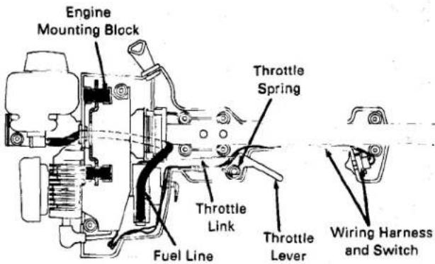
Figure 18
-
Remove the gas line from the carburetor inlet by compressing and sliding the fuel line clamp up onto the fuel line and twisting and pulling on the fuel line.
-
Remove the throttle and switch assemblies and lift the engine from the Left Hand Case.
-
Remove the air cleaner elements and retaining clip.
-
Remove the carburetor by removing the Phillips head screws which pass through the spit back/choke assembly and carburetor.
-
Remove the cooling shroud halves by removing the three screws which attach the shroud to the backing plate, and gently prying open the latch next to the spark plug wire. NOTE: The TC300 and TC400 have a single piece cooling shroud.
-
Remove the flywheel by retaining the starter cup with the starter cup wrench (P/N 45-1390) and removing the flywheel nut (Fig. 24, p. 17). Use the handle of the starter cup wrench to separate the flywheel from the crankshaft taper. The two holes cast into the flywheel should be tapped with a 14'' -20 tap, and two 14'' -20 x 34'' long capscrews used to apply pressure against the crankshaft end until the seat between the flywheel and crankshaft is loosened.
CAUTION: DO NOT attempt to pry the flywheel from the crankshaft or tap on the crankshaft end to loosen the flywheel. The crankshaft is made up of three parts, with the crankshaft ends being pressed onto the crankpin. Prying or striking the crankshaft can result in damage that will require replacement of the short block.
- Remove the CDI (Ignition) Module by removing the two screws which attach the laminations to the cylinder assembly.
- Remove the backing plate assembly by removing the three bolts and two Phillips head screws which pass through the backing plate and backing plate stress plate into the cylinder assembly.
NOTE (TC1500 only): The intake gasket is sealed with a light coating of gasket sealant, and the backing plate may appear to be stuck to the cylinder assembly. - Remove the crankcase pad by squeezing the end of the crankcase pad clip so that it can be passed through the hole in the crankcase.
- Remove the heat shield and muffler by removing the two hex socket capscrews and the Phillips head screw to the heat shield tab. The tab can then be removed by removing the Phillips head screw that fastens it to the cylinder assembly.
Figure 19
DISASSEMBLY, REPAIR, REASSEMBLY INSTRUCTIONS
DISASSEMBLY, REPAIR, REASSEMBLY INSTRUCTIONS
Starter Rope Replacement
- Follow steps 1-5 of Trimmer & Engine Disassembly/Assembly Instructions. NOTE: Do not remove the Recoil Starter Assembly from the Upper Shaft Housing Tube.
- Remove the damaged rope from the pulley.
- Knot one end of the replacement rope. Align the cut-out sections of the Drum and the metal Ratchet Cover. Feed the un-knotted end of the rope through the clearance hole and into the rope groove in the Drum (Figure 20).
natural_image
Technical line drawing of a mechanical assembly with rotating components and mounting holes (no text or symbols)Figure 20
Wind the rope clockwise onto the drum, slipping the rope under the four retainer tabs (do not wind the drum) until the handle is within 2 inches from the Drum. Continue by rotating the Drum and sliding the rope under the retainer tabs until the rope extends through the widest gap between the rope retainer tabs. Install the rope bushing and handle.
b. TC400 (step 4a or 4b will apply depending upon the style of the starter drum)
Wind the rope clockwise onto the drum, slipping the rope between the retainer and the drum until 2 inches of rope remains. Thread
the end of the rope remaining through the guide slot in the retainer. Install the rope bushing and handle.
- IMPORTANT: Check the starter for proper assembly by extending the starter rope full length. With the rope extended, the starter pulley must be able to be rotated an additional 12 turn in a clockwise direction but not more than 112 turns.
- To reassemble, reverse steps 1-5 in Disassembly Instructions (page 10).
Starter Assembly Replacement.
- Follow steps 1-5 of Trimmer & Engine Disassembly/Assembly Instructions.
- Remove the Recoil Starter Assembly from the Upper Shaft Housing Tube. Retain the tube by passing a bar through the holes in the tube. Twist the Recoil Starter Assembly to remove.
- Press the replacement Recoil Starter Assembly into the Upper Shaft Housing Tube. The slots in the Recoil Starter Assembly which are retained by the Trimmer case halves must be in line with the locating holes in the tube, and the widest gap between rope retainer tabs on the Starter must be rotated 180° from the Pole Clamp slot cut in the tube. NOTE: Press only on the end of the Recoil Starter Assembly.
- IMPORTANT: Check the starter for proper assembly by extending the starter rope full length. With the rope extended, the starter pulley must be able to be rotated and additional 12 turn in a clockwise direction. If the Starter Drum stops rotating before the rope is extended full length, remove one wrap of the Starter Rope by sliding it from under the rope retainer tabs and repeat test procedure. If more than 112 turns are possible, wrap one more turn on the starter.
- To reassemble reverse steps 1-5 in Disassembly Instructions (page 10).
DISASSEMBLY, REPAIR, REASSEMBLY INSTRUCTIONS
Alternate fuel pump system to accommodate internal pulse and/or external fuel source.
- Engine Impulse: Actuates Fuel Pump Diaphragm with alternating pressure-vacuum pulses.
- Fuel Pump Diaphragm: Fluctuates in response to engine impulse. Transfers fuel through Fuel Pump Valves.
- Fuel Inlet: Fuel drawn from tank.
- Inlet Valve: Responds to Fuel Pump Diaphgram. Opens during vacuum pulse. Closes during pressure pulse.
- Outlet Valve: Closes during vacuum pulse. Opens during pressure pulse.
- Filter Screen: Filters fuel on route to Metering Chamber.
- Inlet Needle Valve: Lifts off seat to allow fuel entry into Metering Chamber.
- Throttle Valve: Regulates engine speed as it exposes Primary, Second, and Third Idle holes, then Nozzle for fuel delivery.
- Primary Idle Hole: Only fuel source to engine at Idle position.
- Second Idle Hole: Allows additional fuel flow on acceleration.
- Third Idle Hole: Increases fuel flow at Part Throttle.
-
Idle Needle: Adjust for fuel richness to 3 Idle holes.
-
Idle Take-Off: Fuel entry for Idle holes.
- Idle Port: Fuel reservoir for Idle holes.
- Atmospheric Vent: Allows air pressure against Metering Diaphragm.
- Circuit Plate: Meters fuel from Metering Chamber to Low Speed and High Speed Circuits.
- Metering Diaphragm: Drawn up by vacuum to activate Metering Lever.
- Metering Lever: Lifts Inlet Needle off seat.
- Metering Lever Spring: Transmits force to Metering Lever. Closes Needle Valve as Metering Chamber fills.
- Metering Chamber: Fuel reservoir, feeds to Idle and Nozzle circuits.
- Nozzle Check Valve: Engine vacuum draws Valve open.
- Nozzle Well: Fuel is drawn in from Metering Chamber at high speed.
- Hi Speed Needle: Adjusts for fuel richness at high speeds.
- Nozzle: Increases fuel discharge for high speeds.
- Venturi: Increases air velocity at Nozzle, creating a suction to draw fuel into Throttle Bore.
DISASSEMBLY, REPAIR, REASSEMBLY INSTRUCTIONS
WALBRO CARBURETOR SERVICING
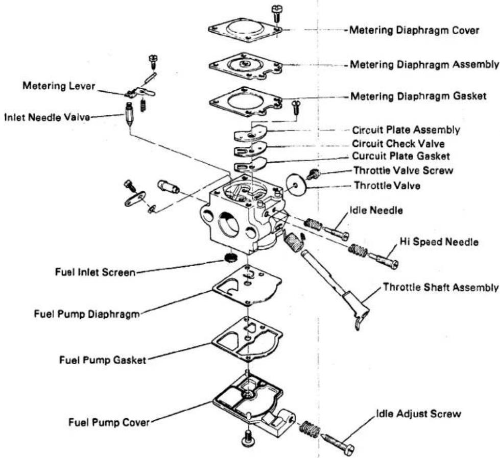
Figure 22
Carburetor Disassembly (Refer to Fig. 22):
- Remove the fuel pump cover screw and pump cover.
- Remove the fuel pump diaphragm and fuel pump gasket.
- Inspect the diaphragm for flatness and continuity. The diaphragm should have no holes. The flapper valves should be flat and free from curling.
- Blow through the external pulse hole on the body casting to insure that there are no obstructions.
- Blow through the internal fuel hole on the body casting to insure that there are no obstructions.
- Remove and discard the filter screen.
-
Remove the four screws and metering diaphragm plate.
-
Remove the metering diaphragm and gasket.
- Inspect the metering diaphragm for holes, dirt and foreign matter.
- Remove the metering lever screw and metering lever components including lever, pin, needle valve and spring.
- Remove the circuit plate screw with the diaphragm and gasket.
- Remove the high and low speed adjustment needles.
- Thoroughly inspect and clean the carburetor, especially all small orifices and openings, using a solvent wash and an air gun.
- Dry the carburetor with air and inspect the operation of the throttle valve and lever.
DISASSEMBLY, REPAIR, REASSEMBLY INSTRUCTIONS
Carburetor Re-Assembly
- Install a new filter screen with any appropriate hollow tube or tool of approximately .300 inch diameter. NOTE: The screen must be pushed in far enough to be below the fuel inlet hole.
- Inspect the circuit plate for flatness and correct if necessary.
- Inspect the new circuit plate diaphragm and gasket for flatness. Install the circuit plate, circuit diaphragm and circuit plate gasket with diaphragm in contact with the plate and gasket in contact with body casting. Use only moderate pressure on the circuit plate screw so as not to warp the circuit plate.
- Install the metering lever components and adjust the metering lever to be flush with the surface of the circuit plate, Fig. 23.
natural_image
Technical line drawing of a mechanical assembly with no visible text or symbolsFigure 23
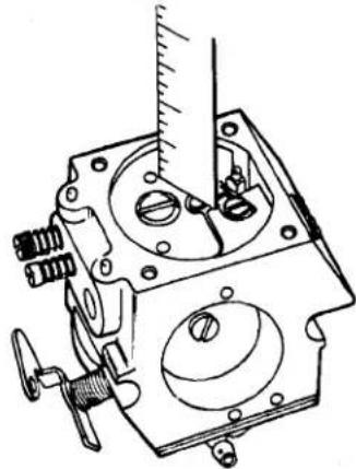
- Install the high and low speed needles and set at approximately 1 and ¼ turns open. The high and low speed letters are indicated on the side of the carburetor casting. The high speed needle is the long needle and the low speed needle is the short needle.
- Install the metering diaphragm and related components as follows: Install the gasket over the locator pins on the casting. Next, install the metering diaphragm over the locator pins on the casting. (The metering plate pin must be in contact with the metering lever.) Next, install the metering diaphragm cover with four screws. The vent hole in the cover should be located opposite the throttle valve.
- With the large single screw, install the fuel pump cover with the fuel pump diaphragm in contact with the body casting and with the fuel pump gasket in contact with the fuel pump cover. The extension on the cover should be located on the same side as the throttle lever.
- Visually inspect the carburetor and tighten all screws.
TROUBLESHOOTING AND TEST PROCEDURES
CUTTER HEAD TROUBLESHOOTING
| Description of Difficulty | Engine Speed | Flexible Drive Shaft | Cutter Head Bearing Housing | Line Feed Assembly | Clutch Assembly | Handle Tube Assembly | Engine Housing |
| Reduced cutting ability | RPM too low | Binding | Bearing worn | Cutting line too short, won't index | Clutch slipping | ||
| Cutting line fails to advance | RPM too low | Driver broken, line swelled from moisture, dirty, line tangled | |||||
| Cutting line pulls back into drum (or tangles) | Cutting line not indexed often enough or prior to engine shut off | ||||||
| Line spoil fails to turn | Not seated in engine or cutting unit | Bearing seized | Driver or drum broken | Bearing grease on clutch drum | Incorrect assembly | ||
| Clutch fails to engage | RPM too low | Not seated in engine or cutting unit | Incorrect assembly | ||||
| Clutch fails to disengage at idle speed | RPM too high | Power shaft snap ring out of groove (some models), clutch spring broken | |||||
| Trimmer vibrates abnormally | Unbalanced cutting unit, bearings worn, dirt accumulation |
DISASSEMBLY, REPAIR, REASSEMBLY INSTRUCTIONS
CLUTCH REPAIR
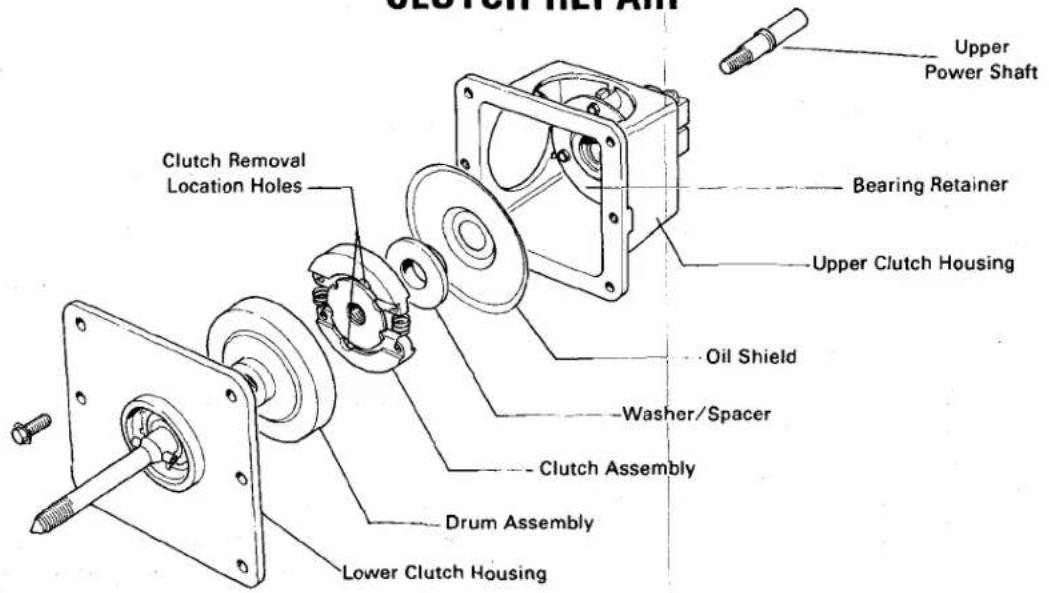
Figure 24
The clutch consists of two assemblies: (Fig. 24):
A. The upper housing containing the upper power shaft, ball bearing, oil shield, clutch spacer, clutch assembly and ...
B. The lower bearing housing and clutch drum which is threaded to the lower housing shaft.
NOTE: The oil shield was not used in early production of the TC-400 clutch assembly. Also, the upper power shaft with the snap ring was changed to a machined shaft with a shoulder. The two shafts are interchangeable. The oil shield may be added to existing clutch assemblies using the upper shaft with the machined ring.
Disassembly & Assembly Instructions
- Remove the cutter head or line feed assembly.
- Remove the clutch housing from the trimmer tube by loosening the housing clamp bolt.
- Remove the six screws securing the upper and lower sections of the clutch housing. Separate the two sections by gently prying them apart.
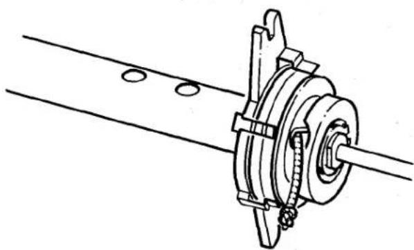
- The clutch assembly (shoes and springs) can be removed with the multipurpose tool P/N #45-1390 (Fig 25). Align the pins on the tool with the holes in the clutch assembly. While supporting the opposite end of the power shaft with a piece
of 3/16 inch square key stock, turn the clutch assembly counterclockwise. The spacer, oil shield and power shaft can now be removed.
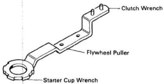
Figure 25 Multipurpose tool (P/N 45-1390)
NOTE: When reassembling the clutch shoe and spring assembly, be sure that the side marked "off" is toward you. The wide flange on the spacer must be against the clutch shoe and spring assembly.
- Remove the three screws in the bearing retainer. The bearing fits loosely and can be pushed out by gently tapping the bearing from the top or clamp end of the housing.
- The shaft and bearings in the lower clutch housing are not serviceable as individual components and must be replaced as an assembly.
DISASSEMBLY, REPAIR, REASSEMBLY INSTRUCTIONS
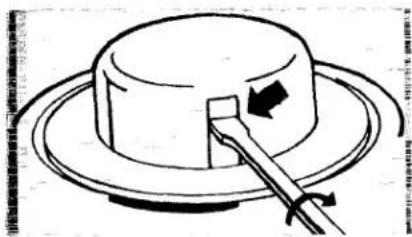
AUTOMATIC LINE FEED REPAIR
- Drain the gasoline from the fuel tank and remove the high tension wire from the spark plug.
- Insert a medium flat screw driver in one of the two window slots in the spool hub and twist. The spool will snap off. (Fig. 26). NOTE: Use as wide a screw driver as will fit in the slot so as not to damage the cap.
natural_image
Simple line drawing of a hat on a circular base with a tool, no text or symbols presentFigure 26
- Hold the drum securely, and unscrew the spool core counterclockwise. The driver will turn off with it.
- Remove the washer and compression spring and slide the drum off the power shaft.
- Clean the debris from the inside and outside of the drum, and remove any debris wrapped around the power shaft.
- Replace any worn or broken parts.
- Reassemble the trimmer head in the reverse order. Be certain that the roll pin on the power shaft is seated in the slot in the drum.
- The spool and spool core are keyed. They must be properly aligned when putting the spool back on. Thread the end of the line through the eyelet. Place the spool on the keyed core and push in place until you hear it click.
TORO