3PAMS27-HH-MZO3 - Air Conditioning Perfect Aire - Free user manual and instructions
Find the device manual for free 3PAMS27-HH-MZO3 Perfect Aire in PDF.

| Type | Portable Air Conditioner |
| Brand | Perfect Aire |
| Model | 3PAMS27-HH-MZO3 |
| Cooling Capacity (BTU) | 12000 BTU |
| Energy Efficiency | EER 10.0 |
| Voltage | 115 V |
| Frequency | 60 Hz |
| Power Consumption | 1200 W |
| Dimensions (W x D x H) | 18 x 13 x 28 in |
| Weight | 60 lbs |
| Refrigerant | R410A |
| Modes | Cool, Fan, Dehumidify |
| Remote Control | Included |
| Timer | 24-hour timer |
| Sleep Mode | Yes |
| Auto Restart | Yes |
| Self-Evaporation | Yes |
| Filter Type | Washable, reusable |
| Noise Level | 55 dB |
| Window Kit Included | Yes (exhaust hose and window bracket) |
| Duct Diameter | 6 inches |
| Maintenance | Clean filter monthly, drain condensation weekly |
| Safety Features | Overheat protection, tip-over auto shut-off |
| Spare Parts | Filter, remote control, exhaust hose |
| Warranty | 1 year manufacturer warranty |
Frequently Asked Questions - 3PAMS27-HH-MZO3 Perfect Aire
User questions about 3PAMS27-HH-MZO3 Perfect Aire
0 question about this device. Answer the ones you know or ask your own.
Ask a new question about this device
Download the instructions for your Air Conditioning in PDF format for free! Find your manual 3PAMS27-HH-MZO3 - Perfect Aire and take your electronic device back in hand. On this page are published all the documents necessary for the use of your device. 3PAMS27-HH-MZO3 by Perfect Aire.
USER MANUAL 3PAMS27-HH-MZO3 Perfect Aire
natural_image
Exterior view of a two-tiered air conditioning unit with ventilation grilles and fan blades (no visible text or symbols)
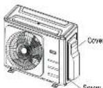
natural_image
Exterior view of a white air conditioning unit with a circular fan and ventilation grille (no visible text or symbols)TABLE OF CONTENTS
SAFETY PRECAUTIONS .... 4
OWNER'S MANUAL
UNIT PARTS AND MAJOR FUNCTIONS....8
UNIT PARTS 8
(A) WALL-MOUNTED TYPE 8
(B) DUCT / CEILING TYPE ____ B
(C) FLOOR AND STANDING TYPE (CONSOLE) 9
(D) COMPACT FOUR-WAY CASSETTE TYPE 9
TROUBLESHOOTING....14
COMMON ISSUES 14
TROUBLESHOOTING 15
ACCESSORIES 17
INSTALLATION MANUAL
INSTALLATION SUMMARY ...... 18
INSTALLATION ORDER....18
BEST INSTALLATION PRACTICES....19
INSTALLATION DIAGRAM....20
SPECIFICATIONS 21
OUTDOOR UNIT INSTALLATION 22
INSTALLATION INSTRUCTIONS - OUTDOOR UNIT 22
STEP 1: SELECT INSTALLATION LOCATION 22
STEP 2: INSTALL DRAIN JOINT 23
STEP 3: ANCHOR OUTDOOR UNIT 23
REFRIGERANT PIPING CONNECTION 25
CONNECTION INSTRUCTIONS - REFRIGERANT PIPING 25
STEP 1: CUT PIPES 25
STEP 2: REMOVE BURRS....25
STEP 3: FLARE PIPE ENDS....25
STEP 4: CONNECT PIPES....26
TABLE OF CONTENTS
(Continued)
INSTALLATION MANUAL CONTINUED
WIRING....28
OUTDOOR UNIT WIRING....29
CHOOSE THE RIGHT CABLE SIZE....29
WIRING FIGURE 30
ONE-TWO MODELS: 30
ONE-THREE MODELS: 33
ONE-FOUR MODELS: 34
ONE-FIVE MODELS: 36
WIRING FIGURE 38
AIR EVACUATION 39
EVACUATION INSTRUCTIONS 39
NOTE ON ADDING REFRIGERANT....40
ELECTRICAL SAFETY CHECK 41
GAS LEAK CHECK 41
TEST RUN 42
BEFORE TEST RUN 42
TEST RUN INSTRUCTIONS 42
FUNCTION OF AUTOMATIC WIRING/PIPING CORRECTION....43
IMPORTANT NOTE:
Read this manual and SAFETY MANUAL(if any) carefully before installing or operating your new air conditioning unit. Make sure to save this manual for future reference.
Please check the applicable models, technical data, F-GAS (if any) and manufacturer information from the "Owner's Manual - Product Fiche" in the packaging of the outdoor unit (European Union products only) or in the packaging of the indoor unit (model dependent)
SAFETY PRECAUTIONS
Read Safety Precautions Before Operation and Installation
Incorrect installation due to ignoring instructions can cause serious damage or injury.
The seriousness of potential damage or injuries is classified as either a WARNING or CAUTION.

WARNING
This symbol indicates the possibility of personnel injury or loss of life.
WARNING
This appliance can be used by children aged from 8 years and above and persons with reduced physical, sensory or mental capabilities or lack of experience and knowledge if they have been given supervision or instruction concerning use of the appliance in a safe way and understand the hazards involved. Children shall not play with the appliance. Cleaning and user maintenance shall not be made by children without supervision
This appliance is not intended for use by persons (including children) with reduced physical, sensory or mental capabilities, or lack of experience and knowledge, unless they have been given supervision or instruction concerning use of the appliance by a person responsible for their safety. Children should be supervised to ensure that they do not play with the appliance.

CAUTION
This symbol indicates the possibility of property damage or serious consequences.
PRODUCT USE WARNINGS
- If an abnormal situation arises (like a burning smell), immediately turn off the unit and disconnect the power. Call your dealer for instructions to avoid electric shock, fire or injury.
- Do not insert fingers, rods or other objects into the air inlet or outlet. This may cause injury, since the fan may be rotating at high speeds.
- Do not use flammable sprays such as hair spray, lacquer or paint near the unit. This may cause fire or combustion.
- Do not operate the air conditioner in places near or around combustible gases. Emitted gas may collect around the unit and cause explosion.
- Do not operate your air conditioner in a wet room such as a bathroom or laundry room. Too much exposure to water can cause electrical components to short circuit.
- Do not expose your body directly to cool air for a prolonged period of time.
- Do not allow children to play with the air conditioner. Children must be supervised around the unit at all times.
- If the air conditioner is used together with burners or other heating devices, thoroughly ventilate the room to avoid oxygen deficiency.
- In certain functional environments, such as kitchens, server rooms, etc., the use of specially designed air-conditioning units is highly recommended.
SAFETY PRECAUTIONS
(Continued)
CAUTION
- Turn off the air conditioner and disconnect the power if you are not going to use it for a long time.
- Turn off and unplug the unit during storms.
• Make sure that water condensation can drain unhindered from the unit. - Do not operate the air conditioner with wet hands. This may cause electric shock.
- Do not use device for any other purpose than its intended use.
- Do not climb onto or place objects on top of the outdoor unit.
- Do not allow the air conditioner to operate for long periods of time with doors or windows open, or if the humidity is very high.
TAKE NOTE OF FUSE SPECIFICATIONS
The air conditioner's circuit board (PCB) is designed with a fuse to provide over current protection.
The specifications of the fuse are printed on the circuit board, such as :
T20A/250VAC(for <24000Btu/h unit), T30A/250VAC(for >24000Btu/h unit)
▲ CLEANING AND
MAINTENANCE WARNINGS
- Turn off the device and disconnect the power before cleaning. Failure to do so can cause electrical shock.
- Do not clean the air conditioner with excessive amounts of water.
- Do not clean the air conditioner with combustible cleaning agents. Combustible cleaning agents can cause fire or deformation.
▲ ELECTRICAL WARNINGS
- Only use the specified power cord. If the power cord is damaged, it must be replaced by the manufacturer, its service agent or similarly qualified persons in order to avoid a hazard.
- Keep power plug clean. Remove any dust or grime that accumulates on or around the plug. Dirty plugs can cause fire or electric shock.
- Do not pull power cord to unplug unit. Hold the plug firmly and pull it from the outlet. Pulling directly on the cord can damage it, which can lead to fire or electric shock.
- Do not modify the length of the power supply cord or use an extension cord to power the unit.
- Do not share the electrical outlet with other appliances. Improper or insufficient power supply can cause fire or electrical shock.
- The product must be properly grounded at the time of installation, or electrical shock may occur.
- For all electrical work, follow all local and national wiring standards, regulations, and the Installation Manual. Connect cables tightly, and clamp them securely to prevent external forces from damaging the terminal. Improper electrical connections can overheat and cause fire, and may also cause shock. All electrical connections must be made according to the Electrical Connection Diagram located on the panels of the indoor and outdoor units.
- All wiring must be properly arranged to ensure that the control board cover can close properly. If the control board cover is not closed properly, it can lead to corrosion and cause the connection points on the terminal to heat up, catch fire, or cause electrical shock.
- If connecting power to fixed wiring, an all-pole disconnection device which has at least 3mm clearances in all poles, and have a leakage current that may exceed 10mA, the residual current device (RCD) having a rated residual operating current not exceeding 30mA, and disconnection must be incorporated in the fixed wiring in accordance with the wiring rules.
SAFETY PRECAUTIONS
(Continued)
PRODUCT INSTALLATION WARNINGS
1 Installation must be performed by an authorized dealer or specialist. Defective installation can cause water leakage, electrical shock, or lire.
2 Installation must be performed according to the installation instructions. Improper installation can cause water leakage, electrical shock, or fire. (In North America, installation must be performed in accordance with the requirement of NEC and CEC by authorized personnel only.)
3 Contact an authorized service technician for repair or maintenance of this unit. This appliance shall be installed in accordance with national wiring regulations.
4 Only use the included accessories, parts, and specified parts for installation. Using non-standard parts can cause water leakage, electrical shock, fire, and can cause the unit to fail.
5 Install the unit in a 3mm location that can support the unit's weight. If the chosen location cannot support the unit's weight, or the installation is not done properly, the unit may drop and cause serious injury and damage.
6 Install drainage piping according to the instructions in this manual. Improper drainage may cause water damage to your home and property.
7 For units that have an auxiliary electric heater, do not install the unit within 1 meter (3 feet) of any combustible materials
Do not install the unit in a location that may be exposed to combustible gas leaks. If combustible gas accumulates around the unit, it may cause lire.
Do not turn on the power until all work has been completed.
10 When moving or relocating the air conditioners, consult experienced service technicians for disconnection and re-installation of the unit.
11 How to install the appliance to its support, please read the information for details in "indoor unit installation" and "outdoor unit installation" sections.
NOTE ABOUT FLUORINATED GASSES
(NOT APPLICABLE TO THE UNIT USING R290 REFRIGERANT)
This air-conditioning unit contains fluorinated greenhouse gases. For specific information on the type of gas and the amount, please refer to the relevant label on the unit itself or the "Owner's Manual - Product Fiche" in the packaging of the outdoor unit. (European Union products only).
2 Installation, service, maintenance and repair of this unit must be performed by a certified technician.
3 Product uninstallation and recycling must be performed by a certified technician
For equipment that contains fluorinated greenhouse gases in quantities of 5 tonnes of CO2 equivalent or more, but of less than 50 tonnes of CO2 equivalent. If the system has a leak-detection system installed, it must be checked for leaks at least every 24 months.
When the unit is checked for leaks, proper record-keeping of all checks is strongly recommended.
SAFETY PRECAUTIONS
(Continued)
| AMOUNT OF REFRIGERANT TO BE CHARGED (KG) | INSTALLATION HEIGHT (M) | MINIMUM ROOM AREA (M2) | AMOUNT OF REFRIGERANT TO BE CHARGED (KG) | INSTALLATION HEIGHT (M) | MINIMUM ROOM AREA (M2) |
| 1.00.6/1.8/2.29/1/1 | 1.95.0/6/1.8/2.33/4 | 1/2.5 | |||
| 1.05.0/6/1.8/2.29.5/1.5/1 | 2.00.0/6/1.8/2.2 | 34.5/4/3 | |||
| 1.10.6/1.8/2.210.5/1.5/1 | 2.05.0/6/1.8/2.2 | 36/4/3 | |||
| 1.15.0/6/1.8/2.211.5/1.5/1 | 2.10.0/6/1.8/2.2 | 38/4.5/3 | |||
| 1.20.6/1.8/2.212.5/1.5/1 | 2.15.0/6/1.8/2.2 | 40/4.5/3 | |||
| 1.25.0/6/1.8/2.213.5/1.5/1 | 2.20.0/6/1.8/2.2 | 41.5/5/3.5 | |||
| 1.30.6/1.8/2.214.5/2/1.5 | 2.25.0/6/1.8/2.2 | 43.5/5/3.5 | |||
| 1.35.0/6/1.8/2.216/2/1.5 | 2.30.0/6/1.8/2.2 | 45.5/5/3.5 | |||
| 1.40.6/1.8/2.217/2/1.5 | 2.35.0/6/1.8/2.2 | 47.5/5.5/4 | |||
| 1.45.0/6/1.8/2.218/2/1.5 | 2.40.0/6/1.8/2.2 | 49.5/5.5/4 | |||
| 1.50.6/1.8/2.219.5/2.5/1.5 | 2.45.0/6/1.8/2.2 | 51.5/6/4 | |||
| 1.55.0/6/1.8/2.221/2.5/2 | 2.50.0/6/1.8/2.2 | 54/6/4 | |||
| 1.60.6/1.8/2.222/2.5/2 | 2.55.0/6/1.8/2.2 | 56/6.5/4.5 | |||
| 1.65.0/6/1.8/2.223.5/3/2 | 2.60.0/6/1.8/2.2 | 58/6.5/4.5 | |||
| 1.70.6/1.8/2.225/3/2 | 2.65.0/6/1.8/2.2 | 60/7/4.5 | |||
| 1.75.0/6/1.8/2.226.5/3/2 | 2.70.0/6/1.8/2.2 | 63/7/5 | |||
| 1.80.6/1.8/2.228/3.5/2 | 2.75.0/6/1.8/2.2 | 65/7.5/5 | |||
| 1.85.0/6/1.8/2.229.5/3.5/2 | 2.80.0/6/1.8/2.2 | 67.5/7.5/5 | |||
| 1.90.6/1.8/2.231/3.5/2 | 2.85.0/6/1.8/2.2 | 70/8/5.5 |
- Reusable mechanical connectors and Jared joints are not allowed indoors. (EN Standard Requirements).
- Mechanical connectors used indoors shall have a rate of not more than 3g/year at 25% of the maximum allowable pressure. When mechanical connectors are reused indoors, scaling parts shall be renewed. When fared joints are reused indoors, the fare part shall be re-labricated. (UL Standard Requirements)
- When mechanical connectors are reused indoors, sealing parts shall be renewed. When cured joints are reused indoors, the are part shall be re-fabricated.
(IEC Standard Requirements)
• Mechanical connectors used indoors shall comply with ISO 14903.
UNIT PARTS AND MAJOR FUNCTIONS
UNIT PARTS
(A) WALL-MOUNTED TYPE
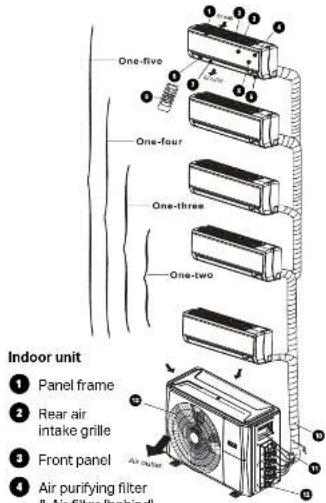
6 Horizontal louver
6 LCD display window
7 Vertical louver
8 Manual control button (behind)
9 Remote control holder
Outdoor unit
10 Drain hose, refrigerant connecting pipe
11 Connective cable
12 Stop valve
13 Fan hood
8
(B) DUCT / CEILING TYPE
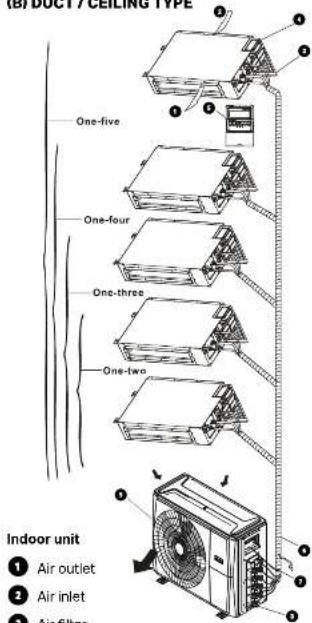
1 Air outlet
2 Air inlet
3 Air filter
4 Electric control cabinet
5 Wire control
Outdoor unit
6 Drain hose, refrigerant connecting pipe
7 Connective cable
8 Stop valve
9 Fan hood
UNIT PARTS AND MAJOR FUNCTIONS
(Continued)
(C) FLOOR AND STANDING TYPE (CONSOLE)
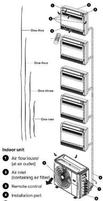
Outdoor unit
6 Drain hose, refrigerant connecting pipe
7 Connective cable
B Stop valve
9 Fan hood
(D) COMPACT FOUR-WAY CASSETTE TYPE
Indoor unit
1 Drain pump (drain water from indoor unit)
2 Drain hose
3 Air outlet
4 Air inlet
Air-in grill
6 Display panel
7 Remote control
Outdoor unit
8 Drain hose, refrigerant connecting pipe
9 Connective cable
10 Stop valve
11 Fan hood
UNIT PARTS AND MAJOR FUNCTIONS
(Continued)
NOTE: Room relative humidity less than 80%. If the air conditioner operates in excess of this figure, the surface of the air conditioner may attract condensation. Please set the vertical airflow louver to its maximum angle (vertically to the floor), and set HIGH fan mode.
When your air conditioner is used outside of the following temperature ranges, certain safety protection features may activate and cause the unit to disable.
| COOL mode HEAT mode DRY mode | |||
| Room Temperature | 62°F - 90°F(17°C - 32°C) | 32°F - 86°F(0°C - 30°C) | 50°F - 90°F(10°C - 32°C) |
| Outdoor Temperature | 32°F - 122°F(0°C - 50°C) | 5°F - 75°F(-15°C - 24°C) | 32°F - 122°F(0°C - 50°C) |
| 5°F - 122°F(-15°C - 50°C)(For models with low-temp cooling systems.) | |||
NOTE: Room relative humidity less than 80%. If the air conditioner operates in excess of this figure, the surface of the air conditioner may attract condensation. Please set the vertical airflow louver to its maximum angle (vertically to the floor), and set HIGH fan mode.
To further optimize the performance of your unit, do the following:
- Keep doors and windows closed.
- Limit energy usage by using TIMER ON and TIMER OFF functions.
- Do not block air inlets or outlets.
• Regularly inspect and clean air filters.
UNIT PARTS AND MAJOR FUNCTIONS
(Continued)
FEATURES
PROTECTION OF THE AIR CONDITIONER
Compressor protection
• The compressor cannot restart for 3 minutes after it stops.
Anti-cold air
- The unit is designed not to blow cold air on HEAT mode, when the indoor heat exchanger is in one of the following three situations and the set temperature has not been reached.
A) When heating has just started.
B) During defrosting.
C) Low temperature heating.
- The indoor or outdoor fan stop running when defrosting (Cooling and heating models only).
Defrosting
- Frost may be generated on the outdoor unit during a heat cycle when outdoor temperature is low and humidity is high resulting in lower heating efficiency in the air conditioner.
• Under these conditions, the air conditioner will stop heating operations and start defrosting automatically.
• The time to defrost may vary from 4 to 10 minutes, depending the outdoor temperature and the amount of frost buildup on the outdoor unit.
Auto-Restart
In case of power failure, the system will immediately stop. When power returns, the Operation light on the indoor unit will flash. To restart the unit, press the ON/OFF button on the remote control. If the system has an auto restart function, the unit will restart using the same settings.
UNIT PARTS AND MAJOR FUNCTIONS
(Continued)
The air conditioner turns to FAN ONLY mode from COOL or HEAT mode.
When the indoor temperature reaches the set temperature setting, the compressor will stop automatically, and the air conditioner turns to FAN only mode. The compressor will start again when the indoor temperature rises on COOL mode or falls on HEAT mode to the set point.
Droplets of water may form on the surface of the indoor unit when cooling occurs in relatively high humidity (defined as higher than 80%). Adjust the horizontal louver to the maximum air outlet position and select HIGH fan speed.
Heating mode
The air conditioner draws in heat from the outdoor unit and releases it via the indoor unit during heating. When the outdoor temperature falls, heat drawn in by the air conditioner decreases accordingly. At the same time, heat loading of the air conditioner increases due to larger difference between indoor and outdoor temperature. If a comfortable temperature cannot be achieved with the air conditioner alone, it is recommended that you use a supplementary heating device.
Lightning or a car wireless telephone operating nearby may cause the unit to malfunction. Disconnect the unit from its power source and then re-connect the unit with the power source again. Push the ON/OFF button on the remote control to restart operations.
ENERGY SAVING TIPS
- DO NOT set the unit to excessive temperature levels.
- While cooling, close the curtains to avoid direct sunlight.
- Doors and windows should be kept closed to keep cool or warm air in the room.
- DO NOT place objects near the air inlet and outlet of the unit. This will reduce the efficiency of the unit.
- Set a timer and use the built-in SLEEP/ECONOMY mode if applicable.
- If you don't plan to use the unit for a long time, remove the batteries from the remote control.
- Clean the air filter every two weeks. A dirty filter can reduce cooling or heating efficiency.
- Adjust louvers properly and avoid direct airflow.
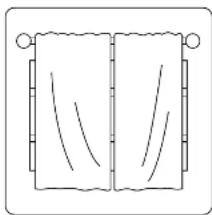
natural_image
Simple line drawing of a scroll with two panels, each showing a wavy line and a straight line (no text or symbols)Closing curtains during heating also helps keep the heat in
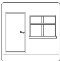
natural_image
Simple line drawing of a door and a window (no text or symbols)Doors and windows should be kept closed
MANUAL OPERATIONS AND MAINTENANCE
While two or more indoor units are simultaneously operating, make sure the modes do not conflict with each other. The heat mode claims precedence over all other modes. If the unit initially started to operate in HEAT mode, the other units can operate in HEAT mode only. For example: If the unit initially started operates under COOL (or FAN) mode, the other units can operate under any mode except HEAT. If one of the unit selects HEAT mode, the other operating units will stop operation and display “---” (for units with display window only) or the auto and operation indication light will flash rapidly, the defrost indication light will turn off, and the timer indication light will remain on (for units without a display window). Alternatively, the defrost and alarm indication light (if applicable) will light up, or the operation indication light will flash rapidly, and the timer indication light will turn off (for the floor and standing type).
MAINTENANCE
If you plan to leave the unit idle for a long time, perform the following tasks:
1 Clean the indoor unit and air filter.
2 Select FAN ONLY mode and let the indoor fan run for a time to dry the inside of the unit.
1 Disconnect the power supply and remove the battery from the remote control.
4 Check components of the outdoor unit periodically. Contact a local dealer or a customer service center if the unit requires servicing.
CAUTION
Before you clean the air conditioner, be sure to switch off the unit and disconnect the main power supply.
OPTIMAL OPERATION
To achieve optimal performance, please note the following:
- Adjust the direction of the air flow so that it is no blowing directly on people.
- Adjust the temperature to achieve the highest possible level of comfort. Do not adjust the unit to excessive temperature levels.
- Close doors and windows in COOL mode or HEAT mode.
- Use the TIMER ON button on the remote controller to select a time you want to start your air conditioner.
- Do not place any object near the air inlet or air outlet, as the efficiency of the air conditioner may be reduced and the air conditioner may stop running.
- Clean the air filter periodically, otherwise cooling or heating performance may be reduced.
- Do not operate unit with horizontal louver in closed position.
WHEN THE AIR CONDITIONER IS TO BE USED AGAIN:
- Use a dry cloth to wipe off the dust accumulated on the rear air intake grille in order to avoid the dust being dispersed from the indoor unit.
- Check that the wiring is not broken off or disconnected.
- Check that the air filter is installed.
- Check if the air outlet or inlet is blocked after the air conditioner has not been used for a long time.
TROUBLESHOOTING
SAFETY PRECAUTIONS
If ANY of the following conditions occurs, turn off your unit immediately!
• The power cord is damaged or abnormally warm
- You smell a burning odor
• The unit emits loud or abnormal sounds
- A power fuse blows or the circuit breaker frequently trips
• Water or other objects fall into or out of the unit
DO NOT ATTEMPT TO FIX THESE YOURSELF! CONTACT AN AUTHORIZED SERVICE PROVIDER IMMEDIATELY!
COMMON ISSUES
The following problems are not a malfunction and in most situations will not require repairs.
Issue Possible Causes
| Unit does not turn on when pressing ON/OFF button | The Unit has a 3-minute protection feature that prevents the unit from overloading. The unit cannot be restarted within three minutes of being turned off. |
| Cooling and Heating Models: If the Operation light and PRE-DEF (Pre-heating/ Defrost) indicators are lit up, the outdoor temperature is too cold and the unit's anti-cold wind is activated in order to defrost the unit. | |
| In Cooling-only Models: If the "Fan Only" indicator is lit up, the outdoor temperature is too cold and the unit's anti-freeze protection is activated in order to defrost the unit. | |
| The unit changes from COOL/HEAT mode to FAN mode | The unit may change its setting to prevent frost from forming on the unit.Once the temperature increases, the unit will start operating in the previously selected mode again. |
| The set temperature has been reached, at which point the unit turns off the compressor.The unit will continue operating when the temperature fluctuates again. | |
| The Indoor unit emits white mist | In humid regions, a large temperature difference between the room's air and the conditioned air can cause white mist. |
| Both the indoor and outdoor units emit white mist | When the unit restarts in HEAT mode after defrosting, white mist may be emitted due to moisture generated from the defrosting process. |
| The Indoor unit makes noises | A squeaking sound is heard when the system is OFF or in COOL mode.The noise is also heard when the drain pump (optional) is in operation. |
| A squeaking sound may occur after running the unit in HEAT mode due to expansion and contraction of the unit's plastic parts. |
TROUBLESHOOTING
(Continued)
Issue Possible Causes
| Both the indoor unit and outdoor unit make noises | A low hissing sound may occur during operation. This is normal and is caused by refrigerant gas flowing through both the indoor and outdoor units. |
| A low hissing sound may be heard when the system starts, has just stopped running or is defrosting. This noise is normal and is caused by the refrigerant gas stopping or changing direction. | |
| The outdoor unit makes noises | The unit will make different sounds based on its current operating mode. |
| Dust is emitted from either the indoor or outdoor unit | The unit may accumulate dust during extended periods of non-use, which will be emitted when the unit is turned on. This can be mitigated by covering the unit during long periods of inactivity. |
| The unit emits a bad odor | The unit may absorb odors from the environment (such as furniture, cooking, cigarettes, etc.) which will be emitted during operations. |
| The unit's filters have become moldy and should be cleaned. | |
| The fan of the outdoor unit does not operate | During operation, the fan speed is controlled to optimize product operation. |
TROUBLESHOOTING
When troubles occur, please check the following points before contacting a repair company.
Problem Possible Causes Solution
| Poor cooling performance | Temperature setting may be higher than ambient room temperature | Lower the temperature setting |
| The heat exchanger on the indoor or outdoor unit is dirty | Clean the affected heat exchanger | |
| The air filter is dirty | Remove the filter and clean it according to instructions | |
| The air inlet or outlet of either unit is blocked | Turn the unit off, remove the obstruction and turn it back on | |
| Doors and windows are open | Make sure that all doors and windows are closed while operating the unit | |
| Excessive heat is generated by sunlight | Close windows and curtains during periods of high heat or bright sunshine | |
| Low refrigerant due to leak or long-term use | Check for leaks, re-seal if necessary and top off refrigerant |
TROUBLESHOOTING
(Continued)
Problem Possible Causes Solution
| The unit is not working | Power failure Wait for the power to be restored | |
| The power is turned off Turn on the power | ||
| The fuse is burned out Replace the fuse | ||
| Remote control batteries are dead Replace batteries | ||
| The Unit's 3-minute protection has been activated | Wait three minutes after restarting the unit | |
| The unit starts and stops frequently | There's too much or too little refrigerant in the system | Check for leaks and recharge the system with refrigerant. |
| There's air or incompressible gas or moisture has entered the system. | Evacuate and recharge the system with refrigerant | |
| System circuit is blocked | Determine which circuit is blocked and replace the malfunctioning piece of equipment | |
| The compressor is broken Replace the compressor | ||
| The voltage is too high or too low | Install a manostat to regulate the voltage | |
| Poor heating performance | The outdoor temperature is lower than 44.5°F (7°C) | Check for leaks and recharge the system with refrigerant |
| Cold air is entering through doors and windows | Make sure that all doors and windows are closed during use | |
| Low refrigerant due to leak or long-term use | Check for leaks, re-seal if necessary and top off refrigerant | |
ACCESSORIES
The air conditioning system comes with the following accessories. Use all of the installation parts and accessories to install the air conditioner. Improper installation may result in water leakage, electrical shock and fire, or cause the equipment to fall. The items are not included with the air conditioner must be purchased separately.
| Name of Accessories | Q'ty (pc) Shape | Name of Accessories | Q'ty (pc) Shape | ||
| Manual | 2~4 | Drain Joint(some models) | 1 | ||
| Transfer connectorNOTE: Pipe size may differ from appliance to appliance. To meet different pipe size requirements, sometimes the pipe connections need a transfer connector installed on the outdoor unit. | Optional part(one piece/one indoor unit) | Seal ring(some models) | 1 | ||
| Outdoor UnitAnti-Vibration Pads | 4 | ||||
| Optional part(1-5 pieces for outdoor unit,depending on models) | |||||
OPTIONAL ACCESSORIES
There are two types of remote controls: wired and wireless. Select a remote control based on customer preferences and requirements and install in an appropriate place. Refer to catalogues and technical literature for guidance on selecting a suitable remote control.
| Name Shape Quantity (PC) | |||
| Connecting pipe assembly | Liquid side | 6.35 (1/4 in) | Parts you must purchase separately. Consult the dealer about the proper pipe size of the unit you purchased. |
| 9.52 (3/8in) | |||
| Gas side | 9.52 (3/8in) | ||
| 12.7 (1/2in) | |||
| 16 (5/8in) | |||
INSTALLATION SUMMARY
INSTALLATION ORDER
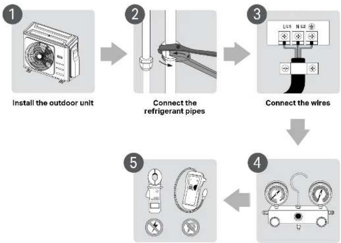
Perform a test run
Evacuate the refrigeration system
INSTALLATION SUMMARY
(Continued)
BEST INSTALLATION PRACTICES
- A SURGE PROTECTOR IS HIGHLY RECOMMENDED TO PREVENT DAMAGE TO THE EQUIPMENT DUE TO ELECTRICAL FAILURE
- VERIFY THE WALL IS PLUMB. AN UNPLUMB WALL WILL CAUSE BLOWER WHEEL TO BE UNBALANCED
- NEVER USE WIRE NUTS ON THE COMMUNICATION CABLE. CRIMP TYPE CONNECTORS ARE ALLOWED
- WIRING BETWEEN INDOOR AND OUTDOOR UNITS IS POLARITY SENSITIVE.(EXAMPLE: IF INDOOR UNIT IS WIRED BLACK ON 1, RED ON 2 AND WHITE ON 3, IT NEEDS TO BE THE SAME ON THE OUTDOOR UNIT)
• A MINIMUM OF 16 AWG, STRANDED 4 WIRE, FT4 RATED, 300 VOLTS WIRE IS NEEDED - BE SURE TO MAKE ALL FLARES WITH AN APPROVED 410A FLARING TOOL
• A MINIMUM OF 10 FT. LINE SET IS REQUIRED - ON SINGLE-ZONE: IF LINE SET IS LONGER THAN 25 FT, YOU WILL NEED TO WEIGH IN THE RECOMMENDED AMOUNT OF REFRIGERANT. SEE INSTALLATION AND OPERATION MANUAL
- ON MULTI-ZONE: THERE IS ENOUGH REFRIGERANT FOR 25 FT. OF LINE SET PER ZONE (EXAMPLE: 3-ZONE = 75 FT. OF LINE SET)
- USE OIL OR NYLOG ON THE THREADS AND TORQUE NUTS TO THE PROPER SPECIFIED VALUE. SEE INSTALLATION AND OPERATION MANUAL
- ALWAYS USE THE SUCTION/GAS LINE TO ADD OR REMOVE REFRIGERANT
- TEST FOR LEAKS BY PRESSURIZING THE SYSTEM WITH MINIMUM 500 POUNDS OF NITROGEN AND HOLD FOR AT LEAST 60 MINUTES
• EVACUATE THE SYSTEM DOWN TO A MINIMUM OF 500 MICRONS AND HOLD FOR 30 MINUTES
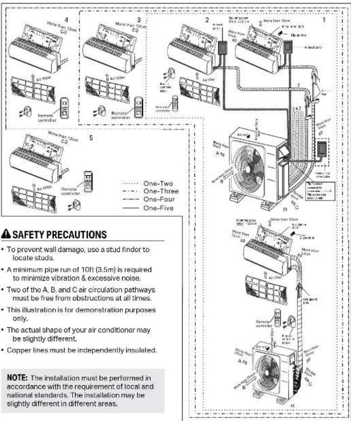
INSTALLATION DIAGRAM
SAFETY PRECAUTIONS
• To prevent wall damage, use a stud finder to locate studs.
- A minimum pipe run of 10ft (3.5m) is required to minimize vibration & excessive noise.
- Two of the A, B, and C air circulation pathways must be free from obstructions at all times.
- This illustration is for demonstration purposes only.
• The actual shape of your air conditioner may be slightly different.
• Copper lines must be independently insulated.
NOTE: The installation must be performed in accordance with the requirement of local and national standards. The installation may be slightly different in different areas.
SPECIFICATIONS
| Number of units that can be used together | Connected units 1-5 units | |
| Compressor stop/start frequency Stop time | 3 min or more | |
| Power source voltage | Voltage fluctuation within ±10% of rated voltage | |
| Voltage drop during start within ±15% of rated voltage | ||
| Interval unbalance within ±3% of rated voltage | ||
Unit: ft./m
| 1 DRIVE 2 | 1 DRIVE 3 | 1 DRIVE 4 | 1 DRIVE 5 | |
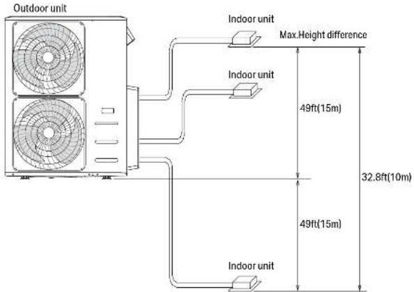
| Max. length for all rooms | 131/40 | 197/60 | 262/80 | 262/80 |
| Max. length for one indoor unit | 82/25 | 98/30 | 115/35 | 115/35 |
| Max. height different between indoor and outdoor unit | 49/15 | 49/15 | 49/15 | 49/15 |
| Max. height different between indoor units | 33/10 | 33/10 | 33/10 | 33/10 |
When installing multiple indoor units with a single outdoor unit, ensure that the length of the refrigerant pipe and the drop height between the indoor and outdoor units meet the requirements illustrated in the following diagram:
OUTDOOR UNIT INSTALLATION
Install the unit by following local codes and regulations, there may be differ slightly between different regions.
INSTALLATION INSTRUCTIONS - OUTDOOR UNIT
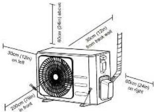
STEP 1: SELECT INSTALLATION LOCATION
Before installing the outdoor unit, you must choose an appropriate location. The following are standards that will help you choose an appropriate location for the unit.
Proper installation locations meet the following standards:
√ Meets all spatial requirements shown in Installation Space Requirements above.
☑ Good air circulation and ventilation
☑ Firm and solid—the location can support the unit and will not vibrate
☑ Noise from the unit will not disturb others
☑ Protected from prolonged periods of direct sunlight or rain
☑ Where snowfall is anticipated, take appropriate measures to prevent ice buildup and coil damage.
DO NOT Install unit in the following locations:
- Near an obstacle that will block air inlets and outlets
Near a public street, crowded areas, or where noise from the unit will disturb others - Near animals or plants that will be harmed by hot air discharge
⊗ Near any source of combustible gas
In a location that is exposed to large amounts of dust
In a location exposed to a excessive amounts of salty air
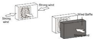
If the unit is exposed to heavy wind: Install unit so that air outlet fan is at a 90° angle to the direction of the wind. If needed, build a barrier in front of the unit to protect it from extremely heavy winds. See Figures below.
If the unit is frequently exposed to heavy rain or snow:
Build a shelter above the unit to protect it from the rain or snow. Be careful not to obstruct airflow around the unit.
If the unit is frequently exposed to salty air (seaside):
Use outdoor unit that is specially designed to resist corrosion.
OUTDOOR UNIT INSTALLATION
(Continued)
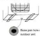
STEP 2: INSTALL DRAIN JOINT
Before bolting the outdoor unit in place, you must install the drain joint at the bottom of the unit. Note that there are two different types of drain joints depending on the type of outdoor unit.
If the drain joint comes with a rubber seal (see Fig. A), do the following:
1 Fit the rubber seal on the end of the drain joint that will connect to the outdoor unit.
2 Insert the drain joint into the hole in the base pan of the unit.
3 Rotate the drain joint 90° until it clicks in place facing the front of the unit.
4 Connect a drain hose extension (not included) to the drain joint to redirect water from the unit during heating mode.
If the drain joint doesn't come with a rubber seal (see Fig. B), do the following:
1 Insert the drain joint into the hole in the base pan of the unit. The drain joint will click in place.
2 Connect a drain hose extension (not included) to the drain joint to redirect water from the unit during heating mode.
IN COLD CLIMATES
In cold climates, make sure that the drain hose is as vertical as possible to ensure swift water drainage. If water drains too slowly, it can freeze in the hose and flood the unit.
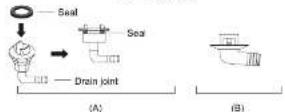
STEP 3: ANCHOR OUTDOOR UNIT
The outdoor unit can be anchored to the ground or to a wall-mounted bracket with bolt(M10). Prepare the installation base of the unit according to the dimensions below.
UNIT MOUNTING DIMENSIONS
The following is a list of different outdoor unit sizes and the distance between their mounting feet. Prepare the installation base of the unit according to the dimensions below.
Outdoor Unit Types and Specifications
Split Type Outdoor Unit
OUTDOOR UNIT INSTALLATION
(Continued)
| OUTDOOR UNITDIMENSIONS (in)W×H×K | MOUNTINGDIMENSIONS (in)Distance A Distance B | |
| 20.85(330mm) | 11.4(290mm) | |
| 31.9×22×4.2(810×658×10mm) | 21.6(549mm) | 12.8(325mm) |
| 33.27×27.5×12.6(845×700×20mm) | 22(560mm) | 13.2(335mm) |
| 35.4×33.85×42.4(900×660×15mm) | 23.2(590mm) | 13.1(333mm) |
| 37.2×31.9×45.55(945×610×95mm) | 25.2(640mm) | 15.95(405mm) |
| 38.98×38×43.58(990×665×45mm) | 24.58(624mm) | 14.4(366mm) |
| 36.93×53.9×15.43(938×1368×92mm) | 24.96(634mm) | 15.9(404mm) |
| 35.4×45×3.8(900×170×850mm) | 23.2(590mm) | 14.88(378mm) |
| 31.5×21.8×43.1(800×654×33mm) | 20.24(514mm) | 13.39(340mm) |
| 33.27×27.6×44.3(845×702×36mm) | 21.26(540mm) | 13.8(350mm) |
| 37.24×31.9×6.53(945×610×420mm) | 26.5(673mm) | 15.87(403mm) |
| 37.24×31.9×6.14(946×610×410mm) | 26.5(673mm) | 15.87(403mm) |
| 37.5×52.5×6.14(952×1333×10mm) | 24.96(634mm) | 15.9(404mm) |
| 37.5×52.5×6.34(952×1333×15mm) | 24.96(634mm) | 15.9(404mm) |
| 35×26.5×43.46(890×673×42mm) | 26.1(662mm) | 13.94(354mm) |
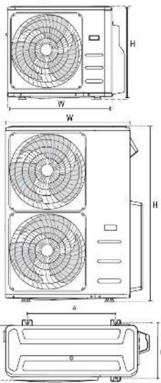
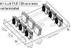
Rows of series installation
The relations between H, A and L are as follows.
L A
L≤1/2H 9.8" / 25 cm or more
L≤H 12 H < L≤H 11.8°/30 cm or more
L > H Can not be installed
NOTES ON DRILLING HOLE IN WALL
You must drill a hole in the wall for the refrigerant piping, and the signal cable that will connect the indoor and outdoor units.
1 Determine the location of the wall hole based on the location of the outdoor unit.
2 Using a 2.5" (65-mm) core drill, drill a hole in the wall.
NOTE: When drilling the wall hole, make sure to avoid wires, plumbing, and other sensitive components.
Place the protective wall cuff in the hole. This protects the edges of the hole and helps seal it when you finish the installation process.
WHEN SELECT A 24K INDOOR UNIT
The 24K indoor unit can only be connected with an A system. If there are two 24K indoor units, they can be connected with A and B systems.
Connective pipe size of an A and B system
Unit: inch
| INDOOR UNIT CAPACITY (BTU/H) | LIQUID GAS | |
| 7K/9K/12K 1⁄4 % | ||
| 12K/18K 1⁄2 % | ||
| 24K | 3⁄4 % | |
REFRIGERANT PIPING CONNECTION
When connecting refrigerant piping, do not let substances or gases other than the specified refrigerant enter the unit. The presence of other gases or substances will lower the unit's capacity, and can cause abnormally high pressure in the refrigeration cycle. This can cause explosion and injury. A Minimum of 10ft line set is required.
CONNECTION INSTRUCTIONS - REFRIGERANT PIPING
CAUTION
- The branching pipe must be installed horizontally. An angle of more than 10^ may cause malfunction.
• DO NOT install the connecting pipe until both indoor and outdoor units have been installed.
• Insulate both the gas and liquid piping to prevent water leakage.
STEP 1: CUT PIPES
When preparing refrigerant pipes, take extra care to cut and flare them properly. This will ensure efficient operation and minimize the need for future maintenance.
1 Measure the distance between the indoor and outdoor units.
2 Using a pipe cutter, cut the pipe a little longer than the measured distance.
3 Make sure that the pipe is cut at a perfect 90° angle.
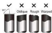
DO NOT DEFORM PIPE WHILE CUTTING
Be extra careful not to damage, dent, or deform the pipe while cutting. This will drastically reduce the heating efficiency of the unit.
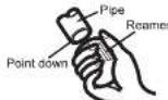
STEP 2: REMOVE BURRS
Burrs can affect the air-tight seal of refrigerant piping connection. They must be completely removed.
1 Hold the pipe at a downward angle to prevent burrs from falling into the pipe.
2 Using a reamer or deburring tool, remove all burrs from the cut section of the pipe.
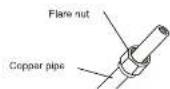
STEP 3: FLARE PIPE ENDS
Proper flaring is essential to achieve an airtight seal.
1 After removing burrs from cut pipe, seal the ends with PVC tape to prevent foreign materials from entering the pipe.
2 Sheath the pipe with insulating material.
3 Place flare nuts on both ends of pipe. Make sure they are facing in the right direction, because you can't put them on or change their direction after flaring.
4 Remove PVC tape from ends of pipe when ready to perform flaring work.
6 Clamp flare form on the end of the pipe. The end of the pipe must extend beyond the flare form.
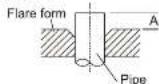
6 Place flaring tool onto the form.
REFRIGERANT PIPING CONNECTION
(Continued)

Turn the handle of the flaring tool clockwise until the pipe is fully flared. Flare the pipe in accordance with the dimensions.
PIPING EXTENSION BEYOND FLARE FORM
| Outer Diameter of A (in) | |
| Pipe (in) Min. Max. | |
| ∅ 0.25 (∅ 6.35mm) | 0.0275 (0.7mm) 0.05 (1.3mm) |
| ∅ 0.375 (∅ 9.52mm) | 0.04 (1.0mm) 0.063 (1.6mm) |
| ∅ 0.5 (∅12.7mm) | 0.04 (1.0mm) 0.07 (1.8mm) |
| ∅ 0.63 (∅ 16mm) | 0.076 (2.0mm) 0.086 (2.2mm) |
| ∅ 0.75 (∅ 15mm) | 0.076 (2.0mm) 0.094 (2.4mm) |
TORQUE REQUIREMENTS
| Outer Diameter of Pipe (in) | Tightening Torque | Flare shape |
| 0.25 ( 6.35mm) | 13 - 15 ft-lbs | |
| 0.375 ( 9.52mm) | 23 - 29 ft-lbs | |
| 0.5 ( 12.7mm) | 36 - 43 ft-lbs | |
| 0.63 ( 16mm) | 42 - 52 ft-lbs | |
| 0.75 ( 19mm) | 49 - 74 ft-lbs |

DO NOT USE EXCESSIVE TORQUE
Excessive force can break the nut or damage the refrigerant piping. You must not exceed torque requirements shown in the table above.

Remove the flaring tool and flare form, then inspect the end of the pipe for cracks and even flaring.
STEP 4: CONNECT PIPES
Connect the copper pipes to the indoor unit first, then connect it to the outdoor unit. You should first connect the low-pressure pipe, then the high pressure pipe.

When connecting the flare nuts, apply a thin coat of refrigeration oil to the flared ends of the pipes.

Align the center of the two pipes that you will connect.
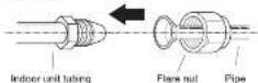

Tighten the flare nut as tightly as possible by hand.

Using a spanner, grip the nut on the unit tubing.

While firmly gripping the nut, use a torque wrench to tighten the flare nut according to the torque values in above table.
NOTE: Torque from tightening the flare nut can snap off other parts of valve.
CAUTION
- Ensure to wrap insulation around the piping. Direct contact with the bare piping may result in burns or frostbite.
• Make sure the pipe is properly connected. Over tightening may damage the bell mouth and under tightening may lead to leakage.
REFRIGERANT PIPING CONNECTION
(Continued)
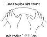
NOTE ON MINIMUM BEND RADIUS
Carefully bend the tubing in the middle according to the diagram below. DO NOT bend the tubing more than 90° or more than 3 times.

After connecting the copper pipes to the indoor unit, wrap the power cable, signal cable and the piping together with binding tape.
NOTE: DO NOT intertwine signal cable with other wires. While bundling these items together, do not intertwine or cross the signal cable with any other wiring.

Thread this pipeline through the wall and connect it to the outdoor unit.

Insulate all the piping, including the valves of the outdoor unit.

Open the stop valves of the outdoor unit to start the flow of the refrigerant between the indoor and outdoor unit.
CAUTION
Check to make sure there is no refrigerant leak after completing the installation work. If there is a refrigerant leak, ventilate the area immediately and evacuate the system (refer to the Air Evacuation section of this manual).
WIRING

BEFORE PERFORMING ANY ELECTRICAL WORK, READ THESE REGULATIONS
1 All wiring must comply with local and national electrical codes, regulations and must be installed by a licensed electrician.
2 All electrical connections must be made according to the Electrical Connection Diagram located on the panels of the indoor and outdoor units.
3 If there is a serious safety issue with the power supply, stop work immediately. Explain your reasoning to the client, and refuse to install the unit until the safety issue is properly resolved.
4 Power voltage should be within 90-110% of rated voltage. Insufficient power supply can cause malfunction, electrical shock, or fire.
6 If connecting power to fixed wiring, a surge protector and main power switch should be installed.
6 If connecting power to fixed wiring, a switch or circuit breaker that disconnects all poles and has a contact separation of at least 1/8in (3mm) must be incorporated in the fixed wiring. The qualified technician must use an approved circuit breaker or switch.
7 Only connect the unit to an individual branch circuit outlet. Do not connect another appliance to that outlet.
8 Make sure to properly ground the air conditioner.
9 Every wire must be firmly connected. Loose wiring can cause the terminal to overheat, resulting in product malfunction and possible fire.
10 Do not let wires touch or rest against refrigerant tubing, the compressor, or any moving parts within the unit.
11 If the unit has an auxiliary electric heater, it must be installed at least 40in (1m) away from any combustible materials.
12 To avoid getting an electric shock, never touch the electrical components soon after the power supply has been turned off. After turning off the power, always wait 10 minutes or more before you touch the electrical components.
13 Make sure that you do not cross your electrical wiring with your signal wiring. This may cause distortion and interference.
14 The unit must be connected to the main outlet. Normally, the power supply must have a impedance of 32 ohms.
15 No other equipment should be connected to the same power circuit.
16 Connect the outdoor wires before connecting the indoor wires.
WARNING
BEFORE PERFORMING ANY ELECTRICAL OR WIRING WORK, TURN OFF THE MAIN POWER TO THE SYSTEM.
NOTE ON AIR SWITCH
When the maximum current of the air conditioner is more than 16A, an air switch or leakage protection switch with protective device shall be used (purchased separately). The appliance should be wired according to NEC and CEC requirements.
(A)
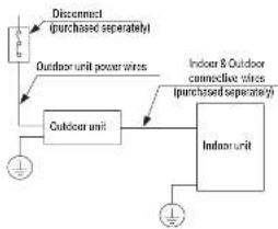
flowchart
graph TD
    A["Outdoor unit"] -->|Disconnect (purchased separately)| B["Outdoor unit power wires"]
    A --> C["Indoor unit"]
    C --> D["Indoor & Outdoor connective wires (purchased separately)"]
    C --> E["Indoor unit"]
    E --> F["Ground"]
NOTE: The cographs are for explanation purpose only. Your machine may be slightly different. The actual shape shall prevail.
WIRING
(Continued)
OUTDOOR UNIT WIRING
WARNING
BEFORE PERFORMING ANY ELECTRICAL OR WIRING WORK, TURN OFF THE MAIN POWER TO THE SYSTEM.

Prepare the cable for connection a. You must first choose the right cable size. Be sure to use H07RN-F(14-4 AWG) cables.
NOTE: In North America, choose the cable type according to the local electrical codes and regulations.
Minimum Cross-Sectional Area of wer and Signal Cables (For referen
| Rated Current of Appliance (A) | Nominal Cross Sectional Area ( mm^2) |
| >3 and < 60.75 | |
| >6 and < 10.1 | |
| >10 and < 16 1.5 | |
| >16 and ≤ 25 2.5 | |
| >25 and ≤ 32 4 | |
| >32 and ≤ 40 6 |
CHOOSE THE RIGHT CABLE SIZE
NOTE: Please choose the right cable size according to the Minimum Circuit Ampacity indicated on the nameplate of the unit.
b. Using wire strippers, strip the rubber jacket from both ends of the signal cable to reveal approximately 5.9" (15cm) of wire.
c. Strip the insulation from the ends.
d. Using a wire crimper,
crimp u-lugs on the ends.
NOTE: When connecting the wires, strictly follow the wiring diagram found inside the electrical box cover.
2 Remove the electric cover of the outdoor unit. If there is no cover on the outdoor unit, take off the bolts from the maintenance board and remove the protection board.
3 Connect the u-lugs to the terminals Match the wire colors/labels with the labels on the terminal block. Firmly screw the u-lug of each wire to its corresponding terminal.
4 Clamp down the cable with the cable clamp.
5 Insulate unused wires with electrical tape. Keep them away from any electrical or metal parts.
6 Reinstall the cover of the electric control box.
HARMONIC DECLARATION
"The equipment M40B-36HFN8-Q complies with IEC 61000-3-12 provided that the short-circuit power Ssc is greater than or equal to 4787737.5 at the interface point between the user's supply and the public system. It is the responsibility of the installer or user of the equipment to ensure, by consultation with the distribution network operator if necessary, that the equipment is connected only to a supply with a short-circuit power Ssc greater than or equal to 4787737.5."
"The equipment M50D-42HFN8-Q complies with IEC 61000-3-12 provided that the shortcircuit power Ssc is greater than or equal to 3190042.5 at the interface point between the user's supply and the public system. It is the responsibility of the installer or user of the equipment to ensure, by consultation with the distribution network operator if necessary, that the equipment is connected only to a supply with a short-circuit power Ssc greater than or equal to 3190042.5."
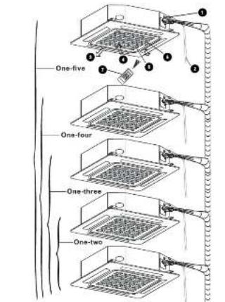
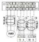
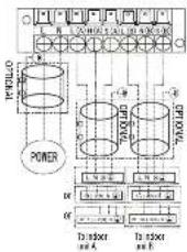
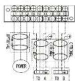
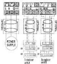
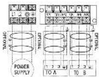
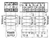
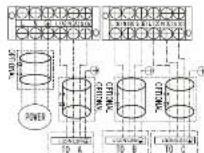
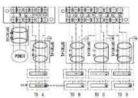
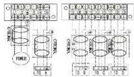
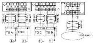
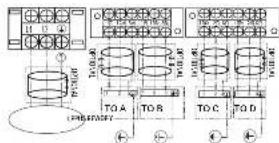
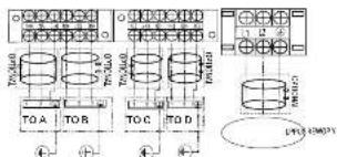
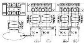
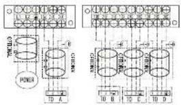
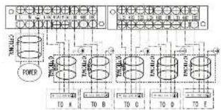
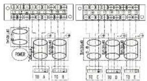
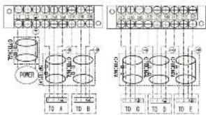
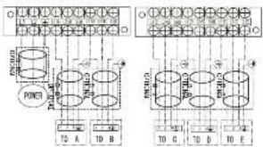
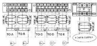
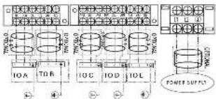
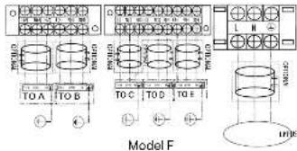
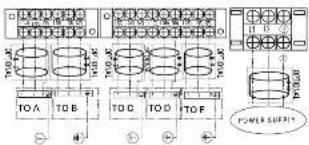
WIRING FIGURE
CAUTION
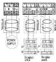
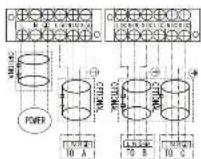
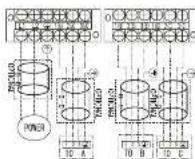
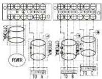
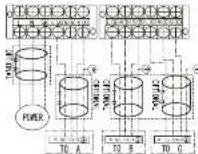
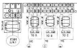
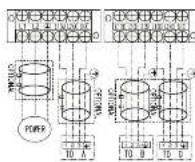
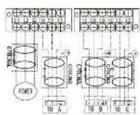
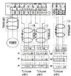
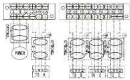
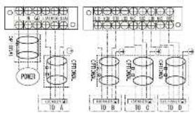
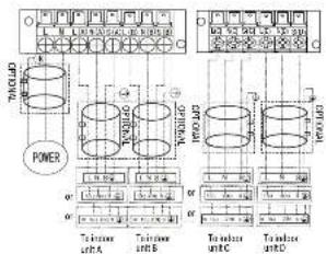
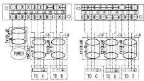
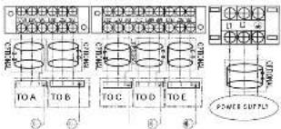
Connect the connective cables to the terminals, as identified, with their matching numbers on the terminal block of the indoor and outdoor units. For example, Terminal L1(A) of the outdoor unit most connect with terminal L1/1 on the indoor unit. The outdoor unit can match different types of indoor unit, the numbers on the terminal block of the indoor unit may be slightly different. Please pay special attention while connecting the wire.
NOTE: Refer to the following figures if end-users wish to perform their own wiring. Run the main power cord through the lower line-outlet of the cord clamp. --- This symbol indicates held wiring.
ONE-TWO MODELS:
| TOMELLO | |||||
| TOMELLO | |||||
| TOMELLO | |||||
| Model A | Model B | ||||
| Model C | Model D | ||||
| TOMELLO | TOMELLO | ||||
| TOMELLO | |||||
| W | L | H | J | 15 | 13.04 | 月 | 84.94 |
| 701045 | TWI (A) | ||||||
| TWI (A) | |||||||
| YAB | |||||||
| 26.7 | *26 | ||||||
| T17.3L0 | T17.4L0 | T17.4L0 |
| 158 | 6% | 158 |
NOTE: Use the magnetic ring (not supplied, optional part) to hirsch the connective cable of indoor and outdoor units after installation. One magnetic ring is used for one cable.
Model L
| TO A | TO B | |
| POWER SLPS* | YG | YG |
| W | L | N | Z | TO | A | B | C |
| TO | L | 100% | 200% | ||||
| FORD SYP-2 | TO A | ||||||
| Model M | |||||||
| W | L | N | Z | TO | A | B | C |
| TO | L | 100% | 200% | ||||
| FORD SYP-2 | TO A | ||||||
| Model N | |||||||
| Model E | Model F | ||
| M | L | H | |
| TOMLO | |||
| TCNLR | |||
| FOSR | |||
| S7001 | |||
| YAS | |||
| 12.00 | 99.54% | 78.36 |
| 12.00 | 99.54% | 78.36 |
| CITRAL | CITRAL | CITRAL |
| 78.36 | 99.54% | 78.36 |
| TAM-01 | TAM-02 | TAM-03 | TAM-04 | TAM-05 |
| 07:00 | 07:01 | 07:02 | 07:03 | 07:04 |
Model G
Model OModel J Model PModel K
WIRING
(Continued)
Model Q
flowchart
graph TD
    A["Power"] --> B["CPU"]
    A --> C["CPU I/O"]
    B --> D["Control Unit"]
    C --> E["Control Unit"]
    D --> F["Output Module 1"]
    D --> G["Output Module 2"]
    E --> H["Output Module 3"]
    style A fill:#f9f,stroke:#333
    style B fill:#ccf,stroke:#333
    style C fill:#ccf,stroke:#333
    style D fill:#cfc,stroke:#333
    style E fill:#cfc,stroke:#333
    style F fill:#fcc,stroke:#333
    style G fill:#fcc,stroke:#333
Model U
Model R
flowchart
graph TD
    A["POWER SUPPLY"] --> B["Transformer Unit A"]
    A --> C["Power Plant Unit B"]
    B --> D["Control Unit"]
    C --> D
    D --> E["Output"]
    style A fill:#f9f,stroke:#333
    style B fill:#ccf,stroke:#333
    style C fill:#cfc,stroke:#333
Model V
Model S
Model T
flowchart
graph TD
    A["POWER SUPPLY"] --> B["Internal Structure"]
    B --> C["Tower unit1"]
    B --> D["Tower unit2"]
    B --> E["Tower unit3"]
    B --> F["Output Unit 1"]
    B --> G["Output Unit 2"]
    style A fill:#f9f,stroke:#333
    style B fill:#ccf,stroke:#333
    style C fill:#cfc,stroke:#333
    style D fill:#fcc,stroke:#333
    style E fill:#cff,stroke:#333
    style F fill:#ffc,stroke:#333
    style G fill:#cfc,stroke:#333
Model W
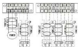
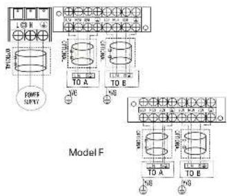
WIRING
(Continued)
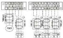
ONE-THREE MODELS:
Model A Model E
Model F
Model B
Model C Model G
WIRING
(Continued)
Model I
flowchart
graph TD
    A["Power"] --> B["Module 1"]
    B --> C["Module 2"]
    C --> D["Tabletor armA"]
    C --> E["Tabletor armB"]
    C --> F["Tabletor armC"]
    G["Module 3"] --> H["Module 4"]
    H --> I["Module 5"]
    I --> J["Tabletor armA"]
    I --> K["Tabletor armB"]
    I --> L["Tabletor armC"]
Model J
ONE-FOUR MODELS:
Model A
flowchart
graph TD
    A["Power Supply"] --> B["Tan"]
    B --> C["Transformer 1"]
    B --> D["Transformer 2"]
    C --> E["Output"]
    D --> F["Output"]
    style A fill:#f9f,stroke:#333
    style B fill:#ccf,stroke:#333
    style C fill:#cfc,stroke:#333
    style D fill:#fcc,stroke:#333
    style E fill:#ffc,stroke:#333
    style F fill:#fcc,stroke:#333
Model B
flowchart
graph TD
    A["Power Supply"] --> B["T0-A"]
    A --> C["T0-B"]
    A --> D["T0-C"]
    A --> E["T0-D"]
    B --> F["Relays"]
    C --> G["Relays"]
    D --> H["Relays"]
    E --> I["Relays"]
    F --> J["Output"]
    G --> K["Output"]
    H --> L["Output"]
    I --> M["Output"]
Model C
WIRING
(Continued)
Model D
Model E
Model G
Model H
Model I
Model J
WIRING
(Continued)
Model K
Model L
Model M
ONE-FIVE MODELS:
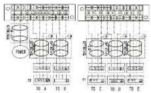
Model A
Model B
Model C
WIRING
(Continued)
Model D
Model H
Model E
Model I
Model J
Model G Model K
WIRING
(Continued)
WIRING FIGURE
CAUTION
After confirmation of the above conditions, follow these guidelines when performing wiring:
• Always have an individual power circuit specifically for the air conditioner. Always follow the circuit diagram posted on the inside of the control cover.
- Screws fastening the wiring in the casing of electrical fittings may come loose during transportation. Because loose screws may cause wire burn-out, check that the screws are tightly fastened.
- Check the specifications for the power source.
- Confirm that electrical capacity is sufficient.
- Confirm that starting voltage is maintained at more than 90 percent of the rated voltage marked on the name plate.
- Confirm that the cable thickness is as specified in the power source specifications.
• Always install an earth leakage circuit breaker in wet or moist areas.
- The following can be caused by a drop in voltage: vibration of a magnetic switch, damaging the contact point, broken fuses, and disturbance of normal functioning.
- Disconnection from a power supply must be incorporated into the fixed wiring. It must have an air gap contact separation of at least 3mm in each active (phase) conductors.
- Before accessing terminals, all supply circuits must be disconnected.
NOTE: To satisfy the EMC compulsory regulations, which is required by the international standard CISPR 14-1:2005/A2:2011 in specific countries or districts, please make sure you apply the correct magnetic rings on your equipment according to the wiring diagram that adhere to the your equipment. Please contact your distributor or installer to get further information and purchase magnetic rings (The supplier of magnetic ring is TDK (model ZCAT3035-1330) or similar).
AIR EVACUATION
PREPARATIONS AND PRECAUTIONS
Air and foreign matter in the refrigerant circuit can cause abnormal rises in pressure, which can damage the air conditioner, reduce its efficiency, and cause injury. Use a vacuum pump and manifold gauge to evacuate the refrigerant circuit, removing any non-condensable gas and moisture from the system.
Evacuation should be performed upon initial installation and when unit is relocated.
BEFORE PERFORMING EVACUATION
☑ Check to make sure the connective pipes between the indoor and outdoor units are connected properly.
☑ Check to make sure all wiring is connected properly.
EVACUATION INSTRUCTIONS
Before using a manifold gauge and a vacuum pump, read their operation manuals to make sure you know how to use them properly.
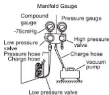
1 Connect the manifold gauge's charge hose to the service port on the outdoor unit's low pressure valve.
2 Connect the manifold gauge's charge hose from the to the vacuum pump.
3 Open the Low Pressure side of the manifold gauge. Keep the High Pressure side closed.
4 Turn on the vacuum pump to evacuate the system.
5 Run the vacuum for at least 15 minutes, or until the Compound Meter reads -76cmHG (-1x10⁵Pa).
6 Close the manifold gauge's Low Pressure valve and turn o the vacuum pump.
7 Wait for 5 minutes, then check that there has been no change in system pressure.
NOTE: If there is no change in system pressure, unscrew the cap from the packed valve (high pressure valve). If there is a change in system pressure, there may be a gas leak.
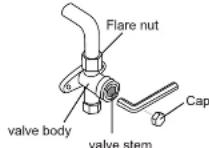
8 Insert hexagonal wrench into the packed valve (high pressure valve) and open the valve by turning the wrench 1/4 counterclockwise. Listen for gas to exit the system, then close the valve after 5 seconds.
9 Watch the Pressure Gauge for one minute to make sure that there is no change in pressure. It should read slightly higher than the atmospheric pressure.
10 Remove the charge hose from the service port.
OPEN VALVE STEMS GENTLY
When opening valve stems, turn the hexagonal wrench until it hits against the stopper. DO NOT try to force the valve to open further.
11 Using hexagonal wrench, fully open both the high pressure and low pressure valves.
12 Tighten valve caps by hand, then tighten it using the proper tool.
13 If the outdoor unit uses all vacuum valves, and the vacuum position is at the main valve, the system is not connected with the indoor unit. The valve must be tightened with a screw nut. Check for gas leaks before operation to prevent leakage.
AIR EVACUATION
(Continued)
NOTE ON ADDING REFRIGERANT
CAUTION
- Refrigerant charging must be performed after wiring, vacuuming, and the leak testing.
- DO NOT exceed the maximum allowable quantity of refrigerant or overcharge the system. Doing so can damage the unit or impact it's functioning.
- Charging with unsuitable substances may cause explosions or accidents. Ensure that the appropriate refrigerant is used.
- Refrigerant containers must be opened slowly. Always use protective gear when charging the system.
• DO NOT mix refrigerants types.
N=2 (one-twin models), N=3 (one-three models), N=4 (one-four models), N=5 (one-five models). Depending on the length of connective piping or the pressure of the evacuated system, you made need to add refrigerant. Refer to table below for refrigerant amounts to be added:
ADDITIONAL REFRIGERANT PER PIPE LENGTH
| Connective Pipe Length (in) | Air Purging Method | Additional Refrigerant | |
| More than (pre-charge pipe length b × 10^3 ) ft/m | Vacuum Pump | Liquid Side: 0.25 ( 6.35m)R410A:(Pipe length - standard length) × 0.13 oz/ft(Pipe length - standard length) × 12 g/m | Liquid Side: 0.375 ( 9.52m)R410A:(Pipe length - standard length) × 0.32 oz/ft(Pipe length - standard length) × 30 g/m |
NOTE: The standard pipe length is 25ft (7.5m).
AIR EVACUATION
(Continued)
SAFETY AND LEAKAGE CHECK
ELECTRICAL SAFETY CHECK
Perform the electrical safety check after completing installation. Cover the following areas:
1 Insulated resistance
The insulated resistance must be more than 2MΩ.
2 Grounding work
After finishing grounding work, measure the grounding resistance by visual detection and using the grounding resistance tester. Make sure the grounding resistance is less than 4Ω.
3 Electrical leakage check
(performing during test while unit is on) During a test operation after completed installation, the use the electroprobe and multimeter to perform an electrical leakage check. Turn off the unit immediately if leakage happens. Try and evaluate different solutions until the unit operates properly.
GAS LEAK CHECK
Perform the electrical safety check after completing installation. Cover the following areas:
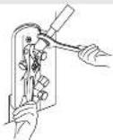
1 Soap water method:
Apply a soap-water solution or a liquid neutral detergent on the indoor unit connection or outdoor unit connections with a soft brush to check for leakage of the connecting points of the piping. If bubbles emerge, the pipes are experiencing leakage.
2 Leak detector
Use the leak detector to check for leakage.
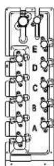
NOTE: The illustration is for example purposes only. The actual order of A, B, C, D, and E on the machine may be slightly different from the unit you purchased but the general shape will remain the same.
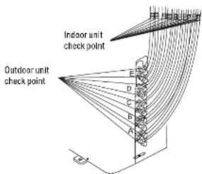
A, B, C, D are points for one-four type.
A, B, C, D, and E are points for the one-five type.
TEST RUN
BEFORE TEST RUN
A test run must be performed after the entire system has been completely installed. Confirm the following points before performing the test:
a) The indoor and outdoor units are properly installed.
b) Piping and wiring are properly connected.
c) No obstacles near the inlet and outlet of the unit that might cause poor performance or product malfunction.
d) The refrigeration system does not leak.
e) Drainage system is unimpeded and draining to a safe location.
f) The heating insulation is properly installed.
g) The grounding wires are properly connected.
h) Length of the piping and additional refrigerant stow capacity have been recorded.
i) The power voltage is the correct voltage for the air conditioner.
CAUTION
Failure to perform the test run may result in unit damage, property damage or personal injury.
TEST RUN INSTRUCTIONS
1 Open both the liquid and gas stop valves.
2 Turn on the main power switch and allow the unit to warm up.
3 Set the air conditioner to COOL mode.
4 For the Indoor Unit
a. Ensure the remote control and its buttons work properly.
b. Ensure the louvers move properly and can be changed using the remote control.
c. Double check to see if the room temperature is being registered correctly.
d. Ensure the indicators on the remote control and the display panel on the indoor unit work properly.
e. Ensure the manual buttons on the indoor unit works properly.
f. Check to see that the drainage system is unimpeded and draining smoothly.
g. Ensure there is no vibration or abnormal noise during operation.
5 For the Outdoor Unit
a. Check to see if the refrigeration system is leaking.
b. Make sure there is no vibration or abnormal noise during operation.
c. Ensure the wind, noise, and water generated by the unit do not disturb your neighbors or pose a safety hazard.
NOTE: If the unit malfunctions or does not operate according to your expectations, please refer to the Troubleshooting section of the Owner's Manual before calling customer service.
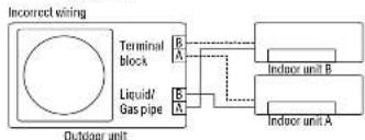
FUNCTION OF AUTOMATIC WIRING/PIPING CORRECTION
AUTOMATIC WIRING / PIPING CORRECTION FUNCTION
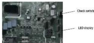
More recent models now feature automatic correction of wiring/piping errors. Press the "check switch" on the outdoor unit PCB board for 5 seconds until the LED displays "CE", indicates that this function is working,
Approximately 5-10 minutes after the switch is pressed, the "CE" disappears, meaning that the wiring/piping error is corrected and all wiring/piping is properly connected.
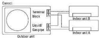
flowchart
graph LR
    A["Outdoor unit"] --> B["Terminal block"]
    B --> C["Liquid/Gas pipe"]
    C --> D["Indoor unit A"]
    C --> E["Indoor unit B"]
    style A fill:#f9f,stroke:#333
    style B fill:#ccf,stroke:#333
    style C fill:#cfc,stroke:#333
    style D fill:#fcc,stroke:#333
    style E fill:#cff,stroke:#333
flowchart
graph TD
    A["Outdoor unit"] --> B["Terminal block"]
    B --> C["Liquid/Gas pipe"]
    C --> D["Indoor unit A"]
    C --> E["Indoor unit B"]
    style A fill:#f9f,stroke:#333
    style B fill:#ccf,stroke:#333
    style C fill:#cfc,stroke:#333
    style D fill:#fcc,stroke:#333
    style E fill:#cff,stroke:#333
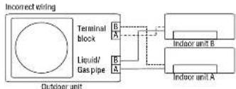
flowchart
graph TD
    A["Outdoor unit"] --> B["Liquid/ Gas pipe"]
    B --> C["Terminal block"]
    C --> D["Indoor unit A"]
    C --> E["Indoor unit B"]
    style A fill:#f9f,stroke:#333
    style B fill:#ccf,stroke:#333
    style C fill:#cfc,stroke:#333
    style D fill:#fcc,stroke:#333
    style E fill:#cff,stroke:#333
HOW TO ACTIVATE THIS FUNCTION
Check that outside temperature is above 5°C. (This function does not work when outside temperature is not above 5°C)
2 Check that the stop valves of the liquid pipe and gas pipe are open.
3 Turn on the breaker and wait at least 2 minutes.
4 Press the check switch on the outdoor PCB board unit LED display "C E".

5401 Dansher Road
Countryside, IL 60525
844-4PA-AIRE | 844-472-2473 | support@perfectaire.us
CANADA SUPPORT 877-997-2473 | supportcanada@perfectaire.us
www.perfectaire.us