
4PTH12A-HE-3.5 - Air Conditioning Perfect Aire - Free user manual and instructions
Find the device manual for free 4PTH12A-HE-3.5 Perfect Aire in PDF.

| Product Type | Packaged Terminal Air Conditioner (PTAC) with heat pump |
| Cooling Capacity | 12,000 BTU/h (estimated based on model number) |
| Heating Capacity | 12,000 BTU/h (heat pump with electric resistance backup) |
| Power Supply | 230V, 15A (dedicated circuit required; time-delay fuse or circuit breaker) |
| Refrigerant | R32 (flammable) |
| Operating Temperature Range (Cooling) | Outdoor: 64°F to 125°F; Indoor: 62°F to 90°F |
| Operating Temperature Range (Heating) | Outdoor: 23°F to 76°F; Indoor: 32°F to 80°F |
| Modes | Cool, Heat, Fan Only, Dry (dehumidify) |
| Fan Speeds | Auto, High, Low |
| Control Type | Built-in electronic control panel with LED display; optional wall thermostat (not included) |
| DIP Switch Configuration | Customizable settings for temperature limits, fan continuous/cycle, electric heat only, low temp protection, wall thermostat enable |
| Filter | Washable foam filter; clean every two weeks |
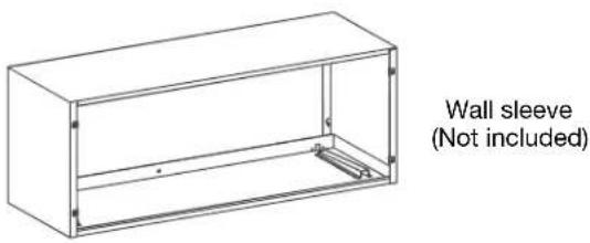
| Installation Type | Through-wall sleeve (wall sleeve not included, must be installed separately) |
| Dimensions (Unit Only) | Approximately 42" W x 16" H x 24" D (typical PTAC, not specified in manual) |
| Weight | Approximately 100 lbs (estimated) |
| Safety Features | Ground fault circuit interrupter (GFCI) on power cord; automatic compressor protection; low temperature protection (optional) |
| Maintenance | Clean front panel with mild detergent; clean outdoor coil professionally; do not use high-pressure spray |
| Warranty | Refer to manufacturer for details (not specified in manual) |
| Accessories Included | Control panel sticker (some models); remote control not included |
Frequently Asked Questions - 4PTH12A-HE-3.5 Perfect Aire
User questions about 4PTH12A-HE-3.5 Perfect Aire
0 question about this device. Answer the ones you know or ask your own.
Ask a new question about this device
Download the instructions for your Air Conditioning in PDF format for free! Find your manual 4PTH12A-HE-3.5 - Perfect Aire and take your electronic device back in hand. On this page are published all the documents necessary for the use of your device. 4PTH12A-HE-3.5 by Perfect Aire.
USER MANUAL 4PTH12A-HE-3.5 Perfect Aire
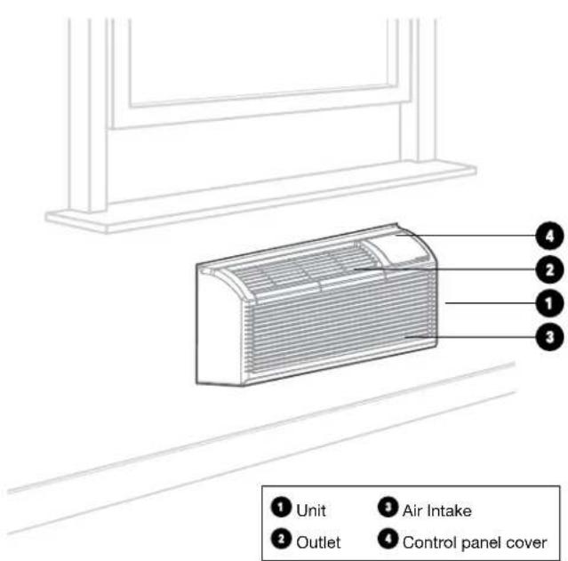
natural_image
Front view of a white air conditioner unit with ventilation grilles and a control panel (no visible text or symbols)TABLE OF CONTENTS
IMPORTANT SAFETY INSTRUCTION....4
BEFORE YOU BEGIN....14
UNIT INSTALLATION....16
DIP SWITCHES....18
DIP SWITCH CONFIGURATIONS by control panel....20
WALL THERMOSTAT TERMINAL (Optional- NOT INCLUDED)....21
OPERATION INSTRUCTIONS....24
CARE & MAINTENANCE....26
TROUBLESHOOTING....27
IMPORTANT NOTE:
Read the manual carefully. Make sure to save this manual for future reference. Illustrations in this manual are for explanatory purposes only, your actual product may look slightly different.
IMPORTANT SAFETY INSTRUCTION
READ THESE SAFETY PRECAUTIONS BEFORE INSTALLATION AND OPERATION.
For your safety, it is important that you read and follow the instructions in this manual to minimize the risk of personal injury, fire or electrical shock.
Inside you will find many helpful hints on how to use and maintain your air conditioner properly. Just a little preventive care on your part can save you a great deal of time and money over the life of your air conditioner. You'll find many answers to common problems in the chart of troubleshooting tips. If you review our chart of Troubleshooting Tips first, you may not need to call for service at all.
To prevent injury to the user or other people and property damage, the following instructions must be followed. Incorrect operation due to ignoring of instructions may cause harm or damage. The seriousness is classified by the following indications.
 | WARNING | The signal word indicates a hazard with a medium level of risk which, if not avoided, may result in death or serious injury. |
 | CAUTION | The signal word indicates a hazard with a low degree of risk which, if not avoided, may result in minor or moderate injury. |
California Proposition 65 Warning
⚠ WARNING: Cancer and reproductive harm - P65warningns.ca.gov

WARNING
- Plug in power plug properly. Otherwise, it may cause electric shock or fire due to excess heat generation. Do not operate or stop the unit by inserting or pulling out the power plug. It may cause electric shock or fire due to heat generation. Do not damage or use an unspecified power cord. It may cause electric shock or fire. If the power cord is damaged, it must be replaced by the manufacturer or an authorized service center or a similarly qualified person in order to avoid a hazard.
- Always install circuit breaker and a dedicated power circuit. Incorrect installation may cause fire and electric shock. Do not operate with wet hands or in damp environment. It may cause electric shock. Do not direct airflow at room occupants only. This could damage your health.
-
Always ensure effective grounding. Incorrect grounding may cause electric shock. Do not allow water to run into electric parts. It may cause failure of machine of electric shock. Do not modify power cord length or share the outlet with other appliances. It may cause electric shock or fire due to heat generation.
-
Unplug the unit if strange sounds, smell, or smoke comes from it. It may cause fire and electric shock. Do not use the socket if it is loose or damaged. It may cause fire and electric shock. Do not open the unit during operation. It may cause electric shock.
- Keep firearms away. It may cause fire. Do not use the power cord close to hating appliances. It may cause fire and electric shock. Do not use the power cord near flammable gas or combustibles, such as gasoline, benzene, thinner, etc. It may cause an explosion or fire.
- Ventilate room before operating air conditioner if there is a gas leakage from another appliance. It may cause explosion, fire and, burns. Do not disassemble or modify unit. It may cause failure and electric shock.

CAUTION
- When the air filter is to be removed, do not touch the metal parts of the unit. It may cause an injury. Ventilate the room well when used together with a stove, etc. An oxygen shortage may occur.
- Do not use strong detergent such as wax or thinner but use a soft cloth. Appearance may be deteriorated due to change of product color or scratching of its surface. Do not clean the air conditioner with water. Water may enter the unit and degrade the insulation. It may cause an electric shock. Do not use for special purposes. Do not use this air conditioner to preserve precision devices, food, pets, plants, and art objects. It may cause deterioration of quality, etc.
- Stop operation and close the window in storm or hurricane. Operation with windows opened may cause wetting of indoor and soaking of household furniture. When the unit is to be cleaned, switch off, and turn off the circuit breaker.
- Do not clean unit when power is on as it may cause fire and electric shock, it may cause an injury.
- Always insert the filters securely. It can be caused failure if operated without filters. Please clean filter once every two weeks.

CAUTION
- Hold the plug by the head of the power plug when taking it out. It may cause electric shock and damage. Turn off the main power switch when not using the unit for a long time. It may cause failure of product or fire.
- Do not place obstacles around air-inlets or inside of air-outlet. It may cause failure of appliance or accident. Do not place heavy object on the power cord and ensure that the cord is not compressed. There is danger of fire or electric shock. Don't drink water drained from air conditioner. It contains contaminants and could make you sick.
- Use caution when unpacking and installing. Sharp edges could cause injury.
- If water enters the unit, turn the unit off at the power outlet and switch off the circuit breaker. Isolate supply by taking the power-plug out
and contact a qualified service technician. This appliance is not intended for use by persons (including children) with reduced physical, sensory or mental capabilities or lack of experience and knowledge, unless they have been given super vision or instruction concerning use of the appliance by a person responsible for their safety.
• Children should be supervised to ensure that they do not play with the appliance.
- If the supply cord is damaged, it must be replaced by the manufacturer, its service agent or similarly qualified persons in order to avoid a hazard.
- The appliance shall be installed in accordance with national wiring regulations.
- Installation must be performed in accordance with the requirement of NEC and CEC by authorized personnel only. Do not operate your air conditioner in a wet room such as a bathroom or laundry room.
- The appliance with electric heater shall have at least 1 meter space to the combustible materials.
- Contact the authorized service technician for repair or maintenance of this unit.
- Contact the authorized installer for installation of this unit.
NOTE
This air conditioner is designed to be operated under the following conditions:
| Cooling operation | Outdoor temp: 6 | 4-(109/79)°F/18-(43/26)°C(64-125° F/18-52°Cfor special tropical models) |
| Indoor temp: 62 | (90/73)° F/17-(32/23)°C | |
| Heating operation | Outdoor temp: 2 | 3-(76/64)° F/-5-(24/18)°C |
| Indoor temp: 32 | (80/66)° F/0-(27/19)°C |
Note: (43/26) °C. It means the dry bulb temperature is 43°C and the wet bulb temperature is 26°C
Note: Performance may be reduced outside of these operating temperatures
The power supply cord contains a current device that senses damage to the power cord. To test your power supply cord do the following:
- Plug in the Air Conditioner.
- The power supply cord will have TWO buttons on the plug head. Press the TEST button, you will notice a click as the RESET button pops out.
- Press the RESET button again, you will notice a click as the button engages.
- The power supply cord is now supplying electricity to the unit. (On some products this is also indicated by a light on the plug head).
NOTE
- The power supply cord with this air conditioner contains a current detection device designed to reduce the risk of fire. In the event that the power cord is damaged, it cannot be repaired – it must be replaced with a cord from the product manufacturer.
- Do not use this device to turn the unit on or off.
- Always make sure the RESET button is pushed in for correct operation.
- The power supply cord must be replaced if it fails to reset when either the TEST button is pushed or if it cannot be reset.
- A new one can be obtained from the product manufacturer.
- If power supply cord is damaged, it cannot be repaired. It MUST be replaced by one obtained from the product manufacturer. When 265V units are to be installed, the power supply must be permanent wiring. Permanent wiring may be done through the accessory subbase. An exposed cord connection on 265V units are not permitted.
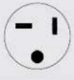
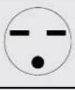
Grounding type wall receptacle
Power supply cord with 3-prong grounding plug and current detection device.

WARNING
ELECTRICAL INFORMATION
The complete electrical rating of your new room air conditioner is stated on the serial plate.
Refer to the rating when checking the electrical requirements.
- Be sure the air conditioner is properly grounded. To minimize shock and fire hazards, proper grounding is important. The power cord is equipped with a three-prong grounding plug for protection against shock hazards.
- Your air conditioner must be used in a properly grounded wall receptacle. If the wall receptacle you intend to use is not adequately grounded or protected by a time delay fuse or circuit breaker, have a qualified electrician install the proper receptacle. Ensure the receptacle is accessible after the unit installation.
- Do not run air conditioner without side protective cover in place. This could result in mechanical damage within the air conditioner.
- Do not use an extension cord or an adapter plug.
Avoid fire hazard or electric shock. Do not use an extension cord or an adapter plug. Do not remove any prongs from the power cord.
FOR YOUR SAFETY
Do not store or use gasoline or other flammable vapors and liquids in the vicinity of this or any other appliance.
PREVENT ACCIDENTS
To reduce the risk of fire, electrical shock, or injury to persons when using your air conditioner, follow basic precautions, including the following:
- Be sure the electrical service is adequate for the model you have chosen. This information can be found on the serial plate, which is located on the side of the cabinet and behind the grille.
- If the air conditioner is to be installed in a window, you will probably want to clean both sides of the glass first. If the window is a triple-trackty pew it has screen panel included, remove the screen completely before installation.
IMPORTANT SAFETY INSTRUCTION
(Continued)
- Be sure the air conditioner has been securely and correctly in stalled according to the installation instructions in this manual. Save this manual for possible future use in removing or installing this unit. When handling the air conditioner, be careful to avoid cuts from sharp metal fins on front and rear coils.
ELECTRONIC WORK (265V MODEL IS NOT INCLUDED)

WARNING
BEFORE PERFORMING ANY ELECTRICAL OR WIRING WORK, TURN OFF THE MAIN POWER TO THE SYSTEM
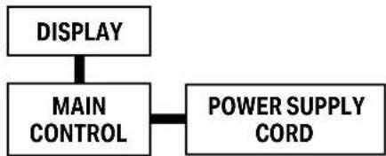
flowchart
graph TD
    A["DISPLAY"] --> B["MAIN CONTROL"]
    B --> C["POWER SUPPLY CORD"]
NOTE: The cographs are for explanation purpose only. Your machine may be slightly different. The actual shape shall prevail.

WARNING
ELECTRICAL REQUIREMENTS
Electrical Shock and Personal Injury Hazard Electrical ground is required on this appliance.
DO NOT ground to a gas line. If cold water pipe is interrupted by plastic, non-metallic gaskets, or other insulating materials,
DO NOT use for grounding. Check with a qualified electrician if you are in doubt as to whether the appliance is properly grounded.
DO NOT modify power supply cord plug. If it does not fit outlet, have a proper outlet installed by a qualified electrician.
DO NOT have a fuse in the neutral or grounding circuit. A fuse in the neutral, or grounding circuit could result in an electrical shock.
DO NOT use an extension cord with this appliance. Failure to follow these instructions could result in electrical shock, serious injury, or death.
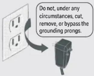
Do not, under any circumstances, remove the power supply cord grounding prong.
NOTE: If codes permit, and a separate grounding wire is used; it is recommended that a qualified electrician determine that the grounding path is adequate and not interrupted by plastic, nonmetallic gaskets, or other insulating materials.
RECEPTACLE WIRING
Receptacle wiring should be a minimum of 14 gauge. Use copper wire only. It is your responsibility to provide proper and adequate receptacle wiring, installed by a qualified electrician.
ELECTRICAL REQUIREMENTS
A time delay fuse or time delay circuit breaker is also required. A separate circuit, serving only this appliance, MUST be provided.
NOTE: for details about the parameters of the electric heating function, see the nameplate on the unit.
NOTE: The shape may be different according to its model:
| Power Cord Power Supply | |
 | 230V,15A |
 | 230V,20A |
 | 230V,30A |

CAUTION:
Risk of fire
flammable materials
IMPORTANT NOTE: Read this manual carefully before installing or operating your new air conditioning unit. Make sure to save this manual for future reference.
Explanation of symbols displayed on the unit
 | CAUTION | This symbol shows that the operation manual should be read carefully. |
 | CAUTION | This symbol shows that a service personnel should be handling this equipment with reference to the installation manual. |
 | CAUTION | This symbol shows that information is available such as the operating manual or installation manual. |
WARNING
(For using R290/R32 refrigerant only)
- Servicing shall only be performed as recommended by the equipment manufacturer. Maintenance and repair requiring the assistance of other skilled personnel shall be carried out under the supervision of the person competent in the use of flammable refrigerants.
- DO NOT modify the length of the power cord or use an extension cord to power the unit.
- DO NOT share a single outlet with other electrical appliances. Improper power supply can cause fire or electrical shock.
- Please follow the instruction carefully to handle, install, clear, service the air conditioner to avoid any damage or hazard. Flammable Refrigerant R32 is used within air conditioner.
- When maintaining or disposing the air conditioner, the refrigerant (R32) shall be recovered properly, shall not discharge to air directly.
- Compliance with national gas regulations shall be observed.
- Keep ventilation openings clear of obstruction.
- The appliance shall be stored so as to prevent mechanical damage from occurring.
-
A warning that the appliance shall be stored in a well-ventilated area where the room size corresponds to the room area as specified for operation.
-
Any person who is involved with working on or breaking into a refrigerant circuit should hold a current valid certificate from an industry-accredited assessment authority, which authorises their competence to handle refrigerants safely in accordance with an industry recognised assessment specification.
Examples for such working procedures are: - breaking into the refrigerating circuit;
- opening of sealed components;
- opening of ventilated enclosures.
- No any open fire or device like switch which may generate spark/arcing shall be around air conditioner to avoid causing ignition of the flammable refrigerant used. Please follow the instruction carefully to store or maintain the air conditioner to prevent mechanical damage from occurring.
- Do not use means to accelerate the defrosting process or to clean, other than those recommended by the manufacturer.
- The appliance shall be stored in a room without continuously operating ignition sources (for example: open flames, an operating gas appliance) and ignition sourcesor (for example: an operating electric heater) close to the appliance. The appliance shall be stored in a room without continuously operating ignition sources (for example: open flames, an operating gas appliance or an operating electric heater).
- Do not pierce or burn.
- Be aware that the refrigerants may not contain an odor.

WARNING
(For using R290/R32 refrigerant only)
TRANSPORT OF EQUIPMENT CONTAINING FLAMMABLE REFRIGERANTS
• See transport regulations.
MARKING OF EQUIPMENT USING SIGNS
• See local regulations.
DISPOSAL OF EQUIPMENT USING FLAMMABLE REFRIGERANTS
• See national regulations.
STORAGE OF EQUIPMENT/APPLIANCES
- The storage of equipment should be in accordance with the manufacturer's instructions.
STORAGE OF PACKED (UNSOLD) EQUIPMENT
- Storage package protection should be constructed such that mechanical damage to the equipment inside the package will not cause a leak of the refrigerant charge.
- The maximum number of pieces of equipment permitted to be stored together will be determined by local regulations.
INFORMATION ON SERVICING
- Checking the area: Prior to beginning work on systems containing flammable refrigerants, safety checks are necessary to ensure that the risk of ignition is minimized. For repair to the refrigerating system, the following precautions shall be complied with prior to conducting work on the system.
-
Work procedure: Work shall be undertaken under a controlled procedure so as to minimize the risk of a flammable gas or vapor being present while the work is being performed.
-
General work area: All maintenance staff and others working in the local area shall be instructed on the nature of work being carried out. Work in confined spaces shall be avoided. The area around the workspace shall be sectioned off. Ensure that the conditions within the area have been made safe by control of flammable material.
- Checking for presence of refrigerant: The area should be checked with an appropriate refrigerant detector prior to and during work, to ensure the technician is aware of potentially flammable atmospheres. Ensure that the leak detection equipment being used is suitable for use with flammable refrigerants, i.e. non-sparking, adequately sealed or intrinsically safe.
- Presence of a fire extinguisher: If any hot work is to be conducted on the refrigeration equipment or any associated parts, appropriate fire extinguishing equipment shall be available to hand. Have a dry powder or CO2 fire extinguisher adjacent to the charging area.
- No ignition sources: No person carrying out work in relation to a refrigeration system which involves exposing any pipe work that contains or has contained flammable refrigerant shall use any sources of ignition in such a manner that it may lead to the risk of fire or explosion. All possible ignition sources, including cigarette smoking, should be kept sufficiently far away from the site of installation, repairing, removing and disposal, during which flammable refrigerant can possibly be released to the surrounding space. Prior to work taking place, the area around the equipment is to be surveyed to make sure that there are no flammable hazards or ignition risks. No Smoking signs shall be displayed.
- Ventilated area: Ensure that the area is in the open or that it is adequately ventilated before breaking into the system or conducting any hot work. A degree of ventilation shall continue during the period that the work is carried out. The ventilation should safely disperse any released refrigerant and preferably expel it externally into the atmosphere.
WARNING
(For using R290/R32 refrigerant only)
8. Checks to the refrigeration equipment:
Where electrical components are being changed, they shall be fit for the purpose and to the correct specification. At all times the manufacturer's maintenance and service guidelines shall be followed. If in doubt consult the manufacturer's technical department for assistance.
The following checks shall be applied to installations using flammable refrigerants:
- The charge size is in accordance with the room size within which the refrigerant containing parts are installed.
- The ventilation machinery and outlets are operating adequately and are not obstructed.
- If an indirect refrigerating circuit is being used, the secondary circuit shall be checked for the presence of refrigerant.
- Marking to the equipment continues to be visible and legible. Markings and signs that are illegible should be corrected.
- Refrigeration pipe or components are installed in a position where they are unlikely to be exposed to any substance which may corrode refrigerant containing components, unless the components are constructed of materials which are inherently resistant to being corroded or are suitably protected against being so corroded.
9. Checks to electrical devices:
-
Repair and maintenance to electrical components should include initial safety checks and component inspection procedures. If a fault exists that could compromise safety, then no electrical supply shall be connected to the circuit until it is satisfactorily dealt with. If the fault cannot be corrected immediately but it is necessary to continue operation, an adequate temporary solution should be used. This should be reported to the owner of the equipment, so all parties are advised.
-
Initial safety checks should include:
- That capacitors are discharged: this shall be done in a safe manner to avoid possibility of sparking.
- That there no live electrical components and wiring are exposed while charging, recovering or purging the system.
- That there is continuity of earth bonding.
REPAIRS TO SEALED COMPONENTS
- During repairs to sealed components, all electrical supplies shall be disconnected from the equipment being worked upon prior to any removal of sealed covers, etc. If it is absolutely necessary to have an electrical supply to equipment during servicing, then a permanently operating form of leak detection shall be located at the most critical point to warn of a potentially hazardous situation.
- Particular attention shall be paid to the following to ensure that by working on electrical components, the casing is not altered in such a way that the level of protection is affected. This shall include damage to cables, excessive number of connections, terminals not made to original specification, damage to seals, incorrect fitting of glands, etc. Ensure that apparatus is mounted securely.
- Ensure that seals or sealing materials have not degraded such that they no longer serve the purpose of preventing the ingress of flammable atmospheres. Replacement parts should be in accordance with the manufacturer's specifications.
NOTE: The use of silicon sealant may inhibit the effectiveness of some types of leak detection equipment. Intrinsically safe components do not have to be isolated prior to working on them.
WARNING
(For using R290/R32 refrigerant only)
REPAIR TO INTRINSICALLY SAFE COMPONENTS
- Do not apply any permanent inductive or capacitance loads to the circuit without ensuring that this will not exceed the permissible voltage and current permitted for the equipment in use. Intrinsically safe components are the only types that can be worked on while live in the presence of a flammable atmosphere. The test apparatus shall be at the correct rating.
- Replace components only with parts specified by the manufacturer. Other parts may result in the ignition of refrigerant in the atmosphere from a leak.
CABLING
- Check that cabling will not be subject to wear, corrosion, excessive pressure, vibration, sharp edges or any other adverse environmental effects. The check shall also take into account the effects of aging or continual vibration from sources such as compressors or fans.
DETECTION OF FLAMMABLE REFRIGERANTS
- Under no circumstances, should potential sources of ignition be used in the searching for or detection of refrigerant leaks. A halide torch (or any other detector using a naked flame) should not be used.
LEAK DETECTION METHODS
- The following leak detection methods are deemed acceptable for systems containing flammable refrigerants. Electronic leak detectors shall be used to detect flammable refrigerants, but the sensitivity may not be adequate, or may need re-calibration. (Detection equipment should be calibrated in a refrigerant-free area.) Ensure that the detector is not a potential source of ignition and is suitable for the refrigerant used. Leak detection equipment should be set at a percentage of the LFL of the refrigerant and shall be calibrated to the refrigerant employed and the appropriate percentage of gas (25 % maximum) is confirmed.
- Leak detection fluids are suitable for use with most refrigerants but the use of detergents containing chlorine shall be avoided as the chlorine may react with the refrigerant and corrode the copper pipework.
- If a leak is suspected, all naked flames should be removed/ extinguished. If a leakage of refrigerant is found which requires brazing, all of the refrigerant should be recovered from the system, or isolated (by means of shut off valves) in a part of the system remote from the leak. Oxygen free nitrogen (OFN) should then be purged through the system both before and during the brazing process.
REMOVAL AND EVACUATION
- When breaking into the refrigerant circuit to make repairs or for any other purpose conventional procedures shall be used. However, it is important that best practice is followed since flammability is a consideration. Opening of the refrigeration systems should not be done by brazing.
The following procedure shall be adhered to:
- Remove refrigerant
- Purge the circuit with inert gas
- Evacuate
- Purge again with inert gas
- Open the circuit by cutting or brazing.
- The refrigerant charge should be recovered into the correct recovery cylinders. The system should be flushed with OFN to render the unit safe. This process may need to be repeated several times. Compressed air or oxygen shall not be used for this task.
- Flushing should be achieved by breaking the vacuum in the system with OFN and continuing to fill until the working pressure is achieved, then venting to atmosphere, and finally pulling down to a vacuum. This process shall be repeated until no refrigerant is within the system.
- When the final OFN charge is used, the system shall be vented down to atmospheric pressure to enable work to take place. This operation is absolutely vital if brazing operations on the pipework are to take place.
- Ensure that the outlet for the vacuum pump is not close to any ignition sources and there is ventilation available.
WARNING
(For using R290/R32 refrigerant only)
CHARGING PROCEDURES
- In addition to conventional charging procedures, the following requirements should be followed. Ensure that contamination of different refrigerants does not occur when using charging equipment. Hoses or lines should be as short as possible to minimize the amount of refrigerant contained in them.
- Cylinders should be kept upright.
- Ensure that the refrigeration system is earthed prior to charging the system with refrigerant.
- Label the system when charging is complete (if not already).
- Extreme care should be taken not to overfill the refrigeration system.
- Prior to recharging the system, it should be pressure tested with OFN. The system should be leak tested on completion of charging but prior to commissioning. A follow up leak test should be carried out prior to leaving the site.
DECOMMISSIONING
- Before carrying out this procedure, it is essential that the technician is completely familiar with the equipment and all its detail. It is recommended good practice that all refrigerants are recovered safely. Prior to the task being carried out, an oil and refrigerant sample should be taken in case analysis is required prior to re-use of reclaimed refrigerant. It is essential that electrical power is available before the task is commenced.
- Become familiar with the equipment and its operation.
• Isolate the system electrically.
• Before attempting the procedure ensure that: - When breaking into the refrigerant circuit to make repairs or for any other purpose, conventional procedures should be used.
- Mechanical handling equipment is available, if required, for handling refrigerant cylinders.
-
Personal protective equipment is available and being used correctly.
-
The recovery process is supervised at all times by a competent person.
- Recovery equipment and cylinders conform to the appropriate standards.
- Pump down refrigerant system, if possible.
- If a vacuum is not possible, make a manifold so that refrigerant can be removed from various parts of the system.
- Make sure that cylinder is situated on the scales before recovery takes place.
- Start the recovery machine and operate in accordance with manufacturer's instructions. Do not overfill cylinders. (No more than 80 % volume liquid charge).
- Do not exceed the maximum working pressure of the cylinder, even temporarily.
- When the cylinders have been filled correctly and the process is completed, make sure that the cylinders and the equipment are removed from the site promptly and all isolation valves on the equipment are closed off.
- Recovered refrigerant should not be charged into another refrigeration system unless it has been cleaned and checked.
LABELLING
- Equipment should be labelled stating that it has been de-commissioned and emptied of refrigerant. The label should be dated and signed. Ensure that there are labels on the equipment stating the equipment contains flammable refrigerant.
RECOVERY
- When removing refrigerant from a system, either for servicing or decommissioning, it is recommended good practice that all refrigerants are removed safely.
- When transferring refrigerant into cylinders, ensure that only appropriate refrigerant recovery cylinders are employed. Ensure that the correct number of cylinders for holding the total system charge is available. All cylinders to be used are designated for the recovered refrigerant and labelled for that refrigerant (i.e. special cylinders for the recovery of refrigerant). Cylinders shall be complete with pressure relief valve and associated shut-off valves in good working
WARNING
(For using R290/R32 refrigerant only)
order. Empty recovery cylinders are evacuated and, if possible, cooled before recovery occurs.
- The recovery equipment shall be in good working order with a set of instructions concerning the equipment that is at hand and shall be suitable for the recovery of flammable refrigerants. In addition, a set of calibrated weighing scales shall be available and in good working order.
- Hoses shall be complete with leak-free disconnect couplings and in good condition. Before using the recovery machine, check that it is in satisfactory working order, has been properly maintained and that any associated electrical components are sealed to prevent ignition in the event of a refrigerant release. Consult manufacturer if in doubt.
- The recovered refrigerant shall be returned to the refrigerant supplier in the correct recovery cylinder, and the relevant Waste Transfer Note arranged. Do not mix refrigerants in recovery units and especially not in cylinders. If compressors or compressor oils are to be removed, ensure that they have been evacuated to an acceptable level to make certain that flammable refrigerant does not remain within the lubricant. The evacuation process shall be carried out prior to returning the compressor to the suppliers. Only electric heating to the compressor body should be employed to accelerate this process. When oil is drained from a system, it should be carried out safely.
- Non-duct connected appliances containing A2L refrigerants with the supply and return air openings in the conditioned space may have the body of the appliance may be installed in open areas such as false ceilings not being used as return air plenums, as long as the conditioned air does not directly communicate with the air of the false ceiling.
BEFORE YOU BEGIN
CAUTION
NOTE: The illustrations in the manual are for explanation purpose only. The design specifications are subject to change without prior notice. Your PTAC may be slightly different.
WHAT YOU NEED TO PURCHASE
PREPARE THE FOLLOWING TOOLS
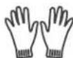
Gloves

Drill

Screwdriver
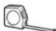
Ruler or tape measure
*Tools not included
Pencil
Level
BEFORE THE INSTALLATION
The installation must be carried out in strict accordance with the instructions in this manual.

Installing your AC should take about 60 minutes.
We recommend doing this with a helper.

We're here if you need us, please contact your local distributor for assistance.
⚠️ INSTALLATION SIZE AND POSITION REQUIREMENTS
⚠️ CAUTION Be careful! There are sharp edges that can cause serious cuts. Please use gloves.
INSTALLATION SIZE CONFIRMATION
Installation size confirmation:
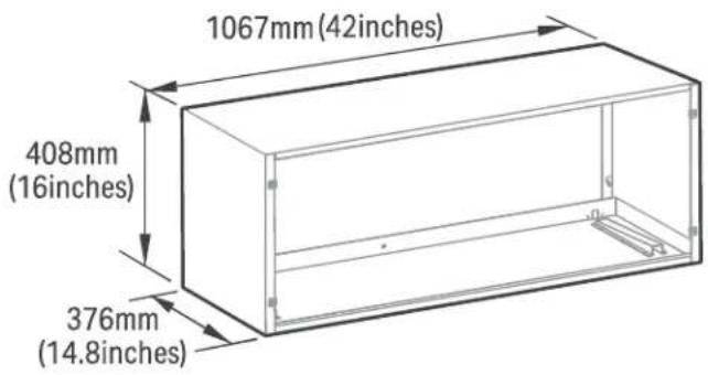
Wall sleeve size requirements (wall hole size should refer to the wall sleeve size)
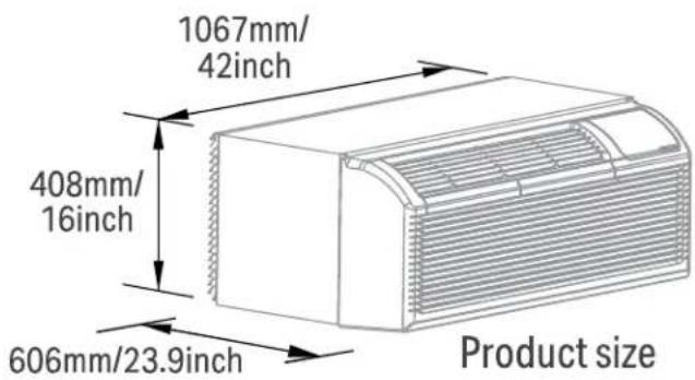
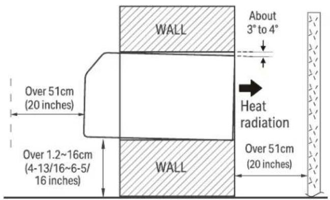
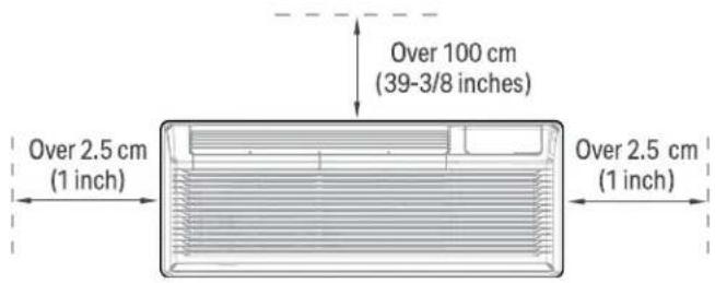
CONFIRMATION OF INSTALLATION POSITION
NOTE: To make the appliance work better, please do not place a barrier in the air outlet.
Confirmation of installation position:
UNIT INSTALLATION
NOTE: Illustrations in this manual are for explanatory purposes. The actual shape of your unit may be slightly different. The actual shape shall prevail.
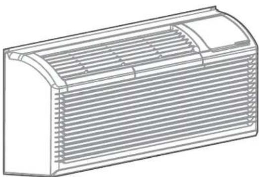
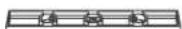
natural_image
Line drawing of a rectangular air conditioner unit with horizontal slats and ventilation slots (no text or symbols)NOTE: Please doing this with a helper, or even two helpers.
What you need:
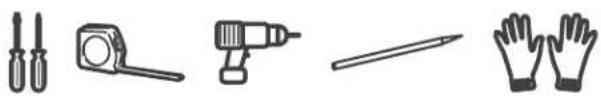
natural_image
Illustration of five different hand tools: a pair of probes, a measuring tool, a drill bit, and a pair of gloves (no text or symbols present)PREPARATIONS FOR UNIT
INSTALLATION
natural_image
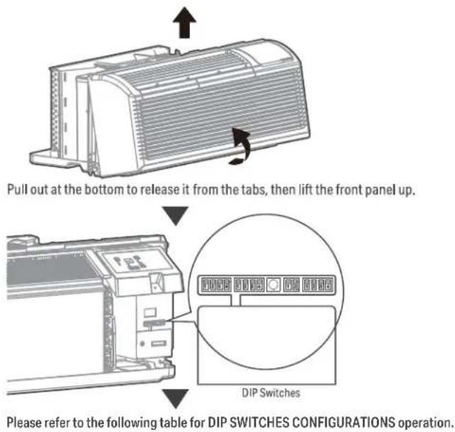
Technical diagram of a heat exchanger or cooling unit with directional arrows indicating flow or movement (no text or symbols present)Pull out at the bottom to release it from the tabs, then lift the front panel up.
1. Attach wall sleeve.
Refer to the installation instruction of sleeve assembly for details. To avoid vibration and noise, make sure the wall sleeve is installed securely and firmly.
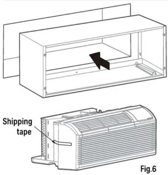
2. Prepare for unit installation.
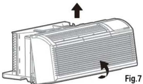
Carefully remove shipping tapes from the front panel. (See Fig.6). Remove the front panel. (See Fig.7)
UNIT INSTALLATION
3. Install and fix the main part of the unit.
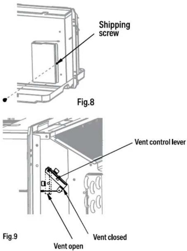
Remove the shipping screw from the vent door. (See Fig.8)
Rotate the vent control lever to either open or close the vent door. (See Fig.9)
NOTE: When vent control lever set at CLOSE, only the air inside the room is circulated and filtered. When set at OPEN, some outdoor air will be drawn into room. This will reduce heating or cooling efficiency.
CAUTION
Do not put obstacles around air-inlet or inside of air-outlet of the unit, such as window curtain etc.
Always insert the filter securely, clean filter once every two weeks as required. Clean water and mild soap or a vacuum adapter can be used to clean the filter.
INSTALL THE UNIT INTO THE WALL SLEEVE
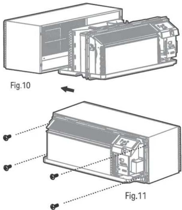
4. Install the unit into the wall sleeve.
Lift unit level and slide unit into wall sleeve until firmly against front of wall sleeve and secure with 4 screws and washers (supplied in the SLEEVE ASSEMBLY) through the unit flange holes. (See Fig.10 and Fig.11)
5. Reinstall front panel.
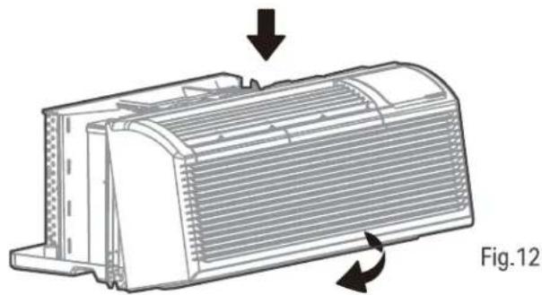
Place tabs over top rail. Push Inward at bottom until panel snaps into place. (See Fig.12)
natural_image
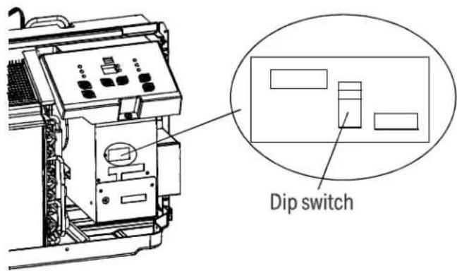
Technical illustration of a heat exchanger component with directional arrows indicating flow or movement (no text or symbols)DIP SWITCHES
CUSTOMIZE YOUR FEATURES
NOTE: Unit must be powered OFF to effectively change their status.
Product function reset operation
DIP SWITCHES CONFIGURATIONS
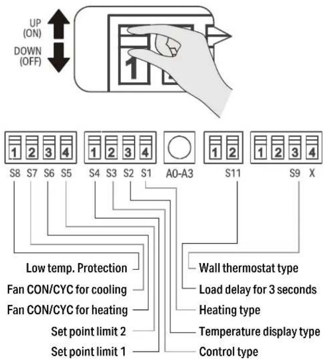
Low Temp. Protection (optional).
If unit senses a room temperature below 32^ F/0°C, the fan motor and electric strip heat will turn on and warm the room to 40^ F/4.4°C. The fan stops a short time after the temperature is satisfied.
Heat and Cool Fan CON/CYC Dip-switches
Allows the fan to operate in continuous or cycle modes while the unit is in heating and cooling mode.
CON (Continuous)
Allows fan to run continuously, circulating air even when the temperature setting has been satisfied. This switch helps to maintain the room temperature closer to the thermostat setting.
CYC (Cycle)
This setting allows the fan to cycle on and off with the compressor or electric heater. The fan stops a short time after the temperature setting is satisfied.
Electric Heat Only (for heat pump unit only)
This setting is typically used for Emergency Heating.
Setpoint Temperature Limits
Provides a restricted range of temperature control.
Wall Thermostat Control
A wired wall thermostat can be connected to the unit. If it is, this dip switch must be moved to the Wall Thermostat Enable Position, before the wall thermostat will begin control.
TABLE 1 - DIP SWITCHES & CONFIGURATIONS
| No. Up (On) Down (Off) Remarks | |||
| S1 Electric heat only Electric heat and pump heat For heat pump only | |||
| S3 Wall thermostat enable Control panel enable | |||
| S4*S5 | UP*UP: 60°F~86°F (16°C~30°C);UP*DOWN: 65°F~78°F (18°C~26°C);DOWN*UP: 63°F~80°F (17°C~27°C);DOWN*DOWN: 68°F~75°F (20°C~24°C) | Two configurations (S4*S5)combine to select set point range. | |
| S6 Fan continuous run for heating Fan cycle for heating | |||
| S7 Fan continuous run for cooling Fan cycle for cooling | |||
| S8 Low temp. protection enable Low temp. protection disable Optional | |||
| S9 (S3UP) Use third party thermostat Use third party thermostat | You can consult with the sales agency or manufacturer for details. | ||
| S9 (S3DOWN) | Use control panel only | Use control panel or third party thermostat | Use control panel or third party thermostat, the other one must be turned off. |
| SW11 | Load delay for 3 seconds | Normal | Optional |
DIP SWITCH CONFIGURATIONS BY CONTROL PANEL
NOTE: Unit must be powered OFF to effectively change their status.
- Press the up and down buttons together for 3 seconds to activate the dip switches configurations by panel control (see Fig.4).
- See Table 1 for Dip Switches configurations and functions by panel control.
NOTE: Press the up and down buttons together for 3 seconds again or no operation within 30 seconds to exit the dip switches configurations by panel control and the unit will save the last settings.
- Display function settings with 2 digitals in LED display window, high (left) for dip switches, low (right) for functions (see Fig.4).
- Press up button to set the dip switches, press down button to set the functions.
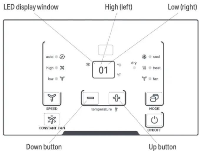
Fig.4
TABLE 1 - DIP SWITCHES & CONFIGURATIONS BY CONTROL PANEL
| No. High (Left) Low (Right) Remarks | ||||
| /0 1-by control panel 0-by dip switches | ||||
| S1 1 1-electric heat only | 0-electric heat and pump heat For Heat Pump unit only | |||
| S3*S9 3 | 3-use control panel or some type of wall thermostat;2-use third party thermostat;1-use third party thermostat; 0-control panel enable. | You can consult with the sales agency or manufacturer for details | ||
| S4*S5 4 | 4-62°F~86°F (17°C~30°C); 3-60°F~86°F (16°C~30°C);2-65°F~78°F (18°C~26°C); 1-63°F~80°F (17°C~27°C);0-68°F~75°F (20°C~24°C) | |||
| S6 6 1-fan continuous run for heating 0-fan cycle for heating | Not available for 1-use third party thermostat | |||
| S7 7 1-fan continuous run for cooling 0-fan cycle for cooling | ||||
| S8 | 8 | 1-low temp. protection enable | 0-low temp. protection disable | Optional |
| S7 | A | 1-front desk control disable | 0-front desk control enable | Optional |
| S11 | B | 1-load delay for 3 seconds | 0-normal | Optional |
NOTE:
- The LED display window will show 00 when you first enter the setting mode, only when you set 01 you can start the next settings.
- To activate front desk control function, you need to pull the dip switch SW7 to DOWN (OFF), and then set the panel control to A0.
- After all set, press up and down buttons together for 3 seconds to exit the operation interface and cut off the power. When re-power on, the settings are activated.
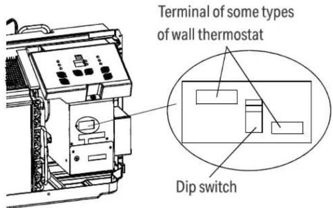
WALL THERMOSTAT TERMINAL (Optional- NOT INCLUDED)
IMPORTANT
Only trained, qualified personnel should access electrical panel on unit and install electrical accessories. Please contact your local electrical contractor, dealer, or distributor for assistance.
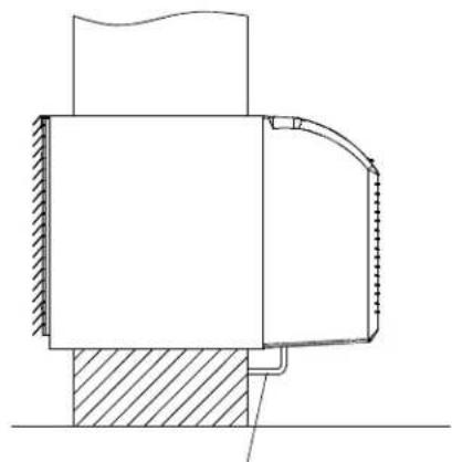
THERMOSTAT WIRE ROUTING
Thermostat wire is field supplied. Recommended wire gauge is 18 to 20 gauge solid thermostat wire.
NOTE: It is recommended that extra wires are run to unit in case any are damaged during installation. Thermostat wire should always be routed around or under, NEVER through, the wall sleeve. The wire should then be routed behind the front panel to the easily accessible terminal connector.
natural_image
Technical cross-sectional diagram of a mechanical assembly (no text or labels)THERMOSTAT WIRE ROUTING
(UNDER SLEEVE, BEHIND FRONT PANEL)
Fig. A - Proper Wire Routing Beneath Unit
NOTE: Refer to thermostat installation instructions for details on installing wall thermostat.
INSTALLATION INSTRUCTION OF SOME TYPES OF WALL THERMOSTAT
You can Consult with the sales agency or manufacturer for details.
- Pull the dip switch to the DOWN (OFF) position as shown below.
- Insert the wire connector of the wall thermostat into the relevant terminal according to different shapes as shown below.
WALL THERMOSTAT TERMINAL (Optional- NOT INCLUDED) (Continued)
INSTALLATION INSTRUCTION OF PTAC 3RD PARTY WALL THERMOSTAT
- Remove the two screws as shown below and take the cover panel down.
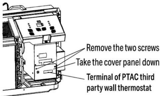
Terminal of PTAC third party wall thermostat (MODE A)
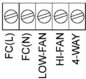
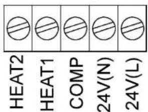
Terminal of PTAC Wall Thermostat (MODE B)
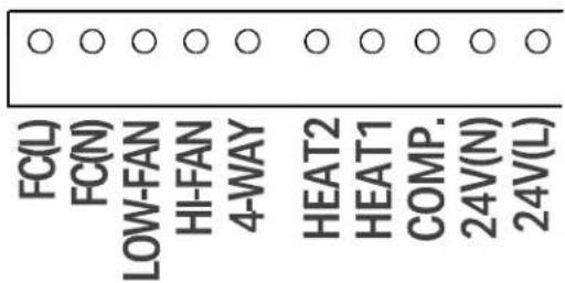
| TERMINAL DESIGNATION | MODE B Wire color | |
| FC(L) Front desk control terminal L Brown | ||
| FC(N) Front desk control terminal N Pink | ||
| LOW-FAN Low fan speed Purple | ||
| HI-FAN High fan speed Green | ||
| 4-WAY | 4-wayvalve; Reverse cycle (Energized in Heat) For heat pump models | Blue |
| HEAT2 | Electrical heater 2 | White |
| HEAT1 | Electrical heater 1 | White |
| COMP | Compressor | Yellow |
| 24V(N) | 24V AC terminal N (Neutral), Common | Black |
| 24V(L) | 24V AC terminal L | Red |
CAUTION
UNIT DAMAGE HAZARD
- Failure to follow this caution may result in equipment damage or improper operation.
- Improper wiring may damage unit electronics. Common busing is not permitted. Damage or erratic operation may result.
WALL THERMOSTAT TERMINAL (Optional- NOT INCLUDED) (Continued)
NOTE:
- Use terminal 4-way for heat pump connection only.
- Suggest set the compressor protection time more than 3 minutes in. If set less than 3 minutes, the compressor will restart delay 3 minutes still.
• Wall thermostat must be heating changeover 4-way valve. - For thermostats that have only one fan speed output (on or auto), the fan speed is determined by how the terminal connector is wired. If Low fan is desired, wire the G output from the thermostat to (LOW-FAN) on the units terminal block.
- If High fan is desired, wire the G output from the thermostat to (HI-FAN) on the units terminal block.
- The range of set temperature of Wall thermostat must be in consonance with the range of DIP switch setting.
- Wall thermostat must be set the type properly in consonance with the unit type: heat pump or no heat pump.
- If the has only one electrical heater output, connect the two terminals of HEAT 1 and HEAT 2, the unit can operate two electrical heaters (only for the unit has two electrical heaters). Otherwise operate one electrical heater.
- Please do not remove the control panel.
FRONT DESK CONTROL
The controller can handle a switch signal from FC(L) and FC(N) input, called front desk control. Input must be 24VAC. If system doesn't receive a 24VAC signal, it will turn unit off; otherwise, the unit runs in normal control. The dip switch can control the FRONT DESK CONTROL feature. The dip switch is on the DOWN position, the unit will be turn off; otherwise, the unit runs in normal control. See Fig B.
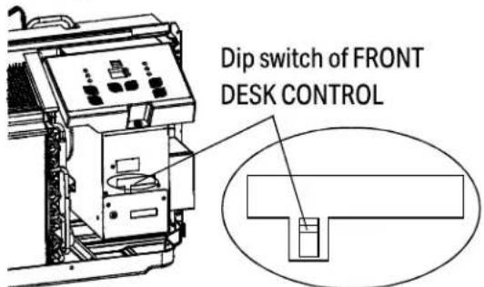
Fig B.
OPERATION INSTRUCTIONS
CONTROL PANEL
NOTE: The control panel keypad will look like Fig.1- For models with a remote control signal receptor, the unit can be controlled by the display panel or by a hand held remote (not included).
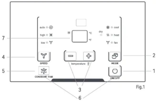
1. POWER - FUNCTION
Press the POWER button to turn the unit on or off.
2. MODE - FUNCTION
Push this button to cycle through the modes from COOL-DRY-HEAT-FAN-COOL. The indicator light beside the "MODE" option will illuminate, identifying the mode selected.
- COOL: Cooling begins automatically when the room temperature is above the set point, and stops when the room temperature is 2^(4^) below the set point. But the compressor will run 5 minutes at least in COOL mode before stopping.
- HEAT: For heat pump models, the unit can alternate to run between in reverse cycle heat mode and electric heater mode according to the difference between the setting temperature and the room temperature.
- The fan motor cycles with the compressor stop.
- DRY: In this mode, the air conditioner will generally operate in the form of a dehumidifier. Since the conditioned space is a closed or sealed area, some degree of cooling will continue.
NOTE:
The reverse cycle and electric heater cannot be run at the same time.
In following cases, it is normal that the reverse cycle does not operate.
- When the outdoor temperature is lower than 4^ C/ 40^ F or the room temperature falls to 4.5^ C/ 8^ F below the set point temperature.
- There is a 3-minute minimum compressor run time at any setting to prevent short cycling. The indoor fan motors start before the compressor and stops after the compressor cycles off.
- Push the S1 on the DIP SWITCHES to UP (ON) position.
- When frost builds up to the evaporator coils, the unit will defrost automatically and the compressor will cycle off.
When you select AUTO mode, the FAN speed will be automatically adjusted at the setting temperature and room temperature.
Fan operation only without heating and cooling.
If the unit has DIP SWITCHES feature, the temperature range can be set and is controlled by DIP SWITCHES. See DIP SWITCHES CONFIGURATIONS on page 18 for details.
3. UP AND DOWN BUTTONS
Push the UP (or DOWN) button to increase (or decrease) the set temperature of the unit in cooling or heating mode. The temperature can be set by increments of 1^ C ( 1^ F). The setting temperature appears in the display.
NOTE:
NOTE: Press and hold "+"and"-" buttons together for 3 seconds to alternate the temperature display between °C & °F scale.
4. FAN (FAN SPEEDS) - FUNCTION
Every time you push this button, the fan speed cycles through the settings as follows: AUTO-HIGH-LOW-AUTO.
NOTE: When you select AUTO mode, the FAN speed will be automatically adjusted at the setting temperature and room temperature. In Dry mode, the fan speed is controlled at Low speed automatically.
5. CONSTANT FAN - FUNCTION
In cooling mode, press the button to turn on or off the constant fan function. When the function is turned on, the constant fan light will illuminate, identifying the fan continuous run for cooling. When the function is turned off, the constant fan light will go out, identifying the fan cycle run with compressor stop.
NOTE: Every time the unit is turned on, the function will work per the DIP SWITCHES CONFIGURATIONS
6. PANEL LOCKING - FUNCTION
Long press the ON/OFF (1) and Constant Fan (5) buttons simultaneously for 5 seconds. The hand held remote control (not included) will still work after the display panel is locked. Turn the lock feature off by repeating the same step.
NOTE: LL will show on the display when the control panel is locked.
7. DISPLAY
Shows the set temperature in °C or °F. While on Fan only mode, it shows the room temperature.
Control code (on some models):
- LC - Buttons on the control panel is not available. The unit can be set by using wire controller only.
- FC - Buttons on the control panel and wire controller are not available. The unit can be set by using FRONT DESK CONTROL only.
Error codes:
• E0 - Failure of EEPROM parameter
• E3 - The fan stall error
• E4 - Main control and Display communication error
• AS - Room temperature sensor error;
- ES - Evaporator temperature sensor error;
• CS - Condenser temperature sensor error;
- OS - Outside temperature sensor error;
• HS - Exhaust temperature sensor error;
• LE - Wire controller error
NOTE: When error occurs, unplug the unit and plug it back in. If error repeats, call for service.
Other codes:
- LO - Room temperature is lower than 0^ / 32^ ;
• HI - Room temperature is higher than 37^ C/ 99^ F;
• FP - Low temp. Protection.
NOTE: All the illustrations in this manual are for explanation purpose only. Your air conditioner may be slightly different. The actual shape shall prevail.
ACCESSORIES
Control panel sticker
NOTE: When the unit displays LC (Options on the control panel are not available. The unit can be set by using wire controller only). You can install the Accessory on the control panel.
NOTE: For some models, there is corresponding operation happened after 3 seconds when pressing any button.
NOTE: When there are differences between USERS MANUAL and Remote controller Illustration on function description, the description on USERS MANUAL shall prevail.
CARE & MAINTENANCE

CAUTION
UNIT DAMAGE HAZARD Failure to follow this caution may result in equipment damage or improper operation. Airflow restriction may cause damage to the unit.
FRONT PANEL AND CASE
- Turn unit off and disconnect power supply. To clean, use water and a mild detergent. Never use bleach and abrasives; Some commercial cleaners may damage or melt the plastic parts.
OUTDOOR COIL
- Coil on outdoor side of unit should be checked regularly. Unit will need to be removed to inspect dirt build-up that will occur on the inside of the coil. If clogged with dirt and soot, coil should be professionally cleaned. Clean inside and outside of outdoor coils regularly.
NOTE: Never use a high-pressure spray on coil.

CAUTION
Failure to follow this caution may result in equipment damage or improper operation.
- Do not operate unit without filters in place. If a filter becomes torn or damaged, it should be replaced immediately.
- Operating without filters in place or with damaged filter will allow dirt and dust to reach indoor coil and reduce cooling, heating, airflow and efficiency of unit. Airflow restriction may cause damage to unit.
The most important thing you can do to maintain unit efficiency is to clean the filters once every two weeks as required. Clogged filters reduce cooling, heating and airflow.
Keeping filters clean will:
• Decrease cost of operation.
- Save energy.
- Prevent clogged indoor coil.
- Reduce risk of premature component failure.
TO CLEAN AIR FILTERS:
Vacuum off heavy soil. Run water through filter. Dry thoroughly before replacing.
REMOVING AIR FILTER
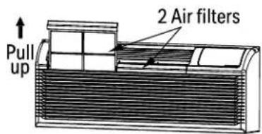
Fig. 13
REPLACING AIR FILTER
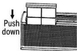
Fig. 14
VENT DOOR FILTER:
IMPORTANT: TURN UNIT OFF BEFORE CLEANING.
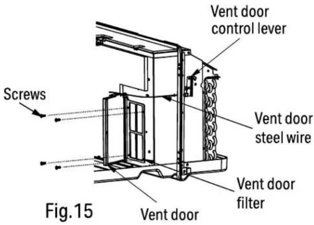
- If the vent door is open, access requires the removal of the unit from the wall sleeve. Clean the vent filter twice a year or as required.
- Make sure to remove the shipping screw from the vent door.(See.Fig.8)
- Rotate the vent control lever to open the vent door. (See. Fig.15)
- Remove four screws from the vent door filter. (See.Fig.15)
- First pull out the vent door steel wire from the hole of the vent door, then take off the vent door and filter. (See.Fig.15)
- Clean the filter with water and mild soap. Dry thoroughly before replacing.
- Replace the vent door and filter, reinstall the four screws.
- Reinsert the vent door steel wire into the hole of the vent door.
TROUBLESHOOTING
Before calling for service, review the chart below.
| Problem What to check | |
| Unit does not start | Unit may have become unplugged. Check that plug is plugged securely in wall receptacle. NOTE: Plug has a test/reset button on it. Make sure that the plug has not tripped. |
| Fuse may have blown. Replace the fuse. See Note 1. | |
| Unit may be off. Reset circuit breaker. See Note 1. | |
| Unit may be in a protection mode. Turn unit on (bottom right button on keypad). | |
| Unit not cooling/heating room | Unit air discharge section is blocked. Make sure that curtains,blinds or furniture are not restricting or blocking unit airflow. |
| Temperature setting is not high or low enough. NOTE: Set point limits may not allow the unit to heat or cool the room to the temperature desired. Check section on dip switch settings. Reset to a lower or higher temperature setting. | |
| Unit air filters are dirty. Remove and clean filters. | |
| Room is excessively hot or cold when unit is started. Allow sufficient amount of time for unit to heat or cool the room. Start heating or cooling early before outdoor temperature,cooking heat or gatherings of people make room uncomfortable. | |
| Vent door left open. Close vent door. Unit may be in a protection mode. Check dip switch and wall thermostat settings for desired comfort. | |
| Compressor is in time delay. Wait approximately 3 minutes for compressor to start. | |
| Display has strange numbers/ characters on it | The unit may be in a protection mode. |
| The unit may be in a protection mode. | |
| Unit making noises Clicking, gurgling and whooshing noises are normal during operation of unit. | |
| Water dripping outside | If a drain kit has not been installed, condensation runoff during very hot and humid weather is normal. See Note 2. If a drain kit has been installed and is connected to a drain system, check gaskets and fittings around drain for leaks and plugs. |
| Water dripping inside | Wall sleeve is not installed level. Wall sleeve must be installed level for proper drainage of condensation. Check that installation is level and make any necessary adjustments. |
| Ice or frost forms on indoor coil | Low outdoor temperature. When outdoor temperature is approximately 55OF or below, frost may form on the indoor coil when unit is in Cooling mode. Switch unit to FAN operation until ice or frost melts. |
| The filters are dirty. Remove and clean filters. | |
| Compressor protection | Power may have cycled,so compressor is in a restart protection. Random Compressor restart - Whenever the unit is plugged in,or power has been restarted, a random compressor restart will occur. After a power outage,the compressor will restart after approximately 3 minutes. Compressor Protection - To prevent short cycling of the compress or, there is a random startup delay of 3 minutes and a minimum compressor run time of 3 minutes. |
| Electric heating failure Clean the evaporator once every three months by professional people. | |
NOTE: 1. If circuit breaker is tripped or fuse is blown more than once, contact a qualified electrician.
- If unit is installed where condensation drainage could drip in an undesirable location, an accessory drain kit should be installed and connected to drain system.

SCAN CODE TO LEAVE A REVIEW
THANK YOU FOR YOUR PURCHASE!
We'd love to hear how you are enjoying your Perfect Aire product! Please take a minute to tell us (and others) about your experience.
Thanks (again!)

5401 Dansher Road Countryside, IL 60525
844-4PA-AIRE | 844-472-2473 | support@perfectaire.us CANADA SUPPORT 877-997-2473 | supportcanada@perfectaire.us www.perfectaire.us
- TABLE OF CONTENTS
- IMPORTANT NOTE:
- IMPORTANT SAFETY INSTRUCTION
- READ THESE SAFETY PRECAUTIONS BEFORE INSTALLATION AND OPERATION.
- WARNING
- CAUTION
- NOTE
- Grounding type wall receptacle
- ELECTRICAL INFORMATION
- FOR YOUR SAFETY
- PREVENT ACCIDENTS
- ELECTRONIC WORK (265V MODEL IS NOT INCLUDED)
- ELECTRICAL REQUIREMENTS
- RECEPTACLE WIRING
- CAUTION:
- (For using R290/R32 refrigerant only)
- TRANSPORT OF EQUIPMENT CONTAINING FLAMMABLE REFRIGERANTS
- MARKING OF EQUIPMENT USING SIGNS
- DISPOSAL OF EQUIPMENT USING FLAMMABLE REFRIGERANTS
- STORAGE OF EQUIPMENT/APPLIANCES
- STORAGE OF PACKED (UNSOLD) EQUIPMENT
- INFORMATION ON SERVICING
- Checks to the refrigeration equipment:
- Checks to electrical devices:
- REPAIRS TO SEALED COMPONENTS
- REPAIR TO INTRINSICALLY SAFE COMPONENTS
- CABLING
- DETECTION OF FLAMMABLE REFRIGERANTS
- LEAK DETECTION METHODS
- REMOVAL AND EVACUATION
- CHARGING PROCEDURES
- DECOMMISSIONING
- LABELLING
- RECOVERY
- BEFORE YOU BEGIN
- BEFORE THE INSTALLATION
- ⚠️ INSTALLATION SIZE AND POSITION REQUIREMENTS
- INSTALLATION SIZE CONFIRMATION
- CONFIRMATION OF INSTALLATION POSITION
- UNIT INSTALLATION
- Attach wall sleeve.
- Prepare for unit installation.
- Install and fix the main part of the unit.
- Remove the shipping screw from the vent door. (See Fig.8)
- INSTALL THE UNIT INTO THE WALL SLEEVE
- Install the unit into the wall sleeve.
- Reinstall front panel.
- DIP SWITCHES
- CUSTOMIZE YOUR FEATURES
- Heat and Cool Fan CON/CYC Dip-switches
- CON (Continuous)
- CYC (Cycle)
- Electric Heat Only (for heat pump unit only)
- Setpoint Temperature Limits
- Wall Thermostat Control
- DIP SWITCH CONFIGURATIONS BY CONTROL PANEL
- NOTE:
- WALL THERMOSTAT TERMINAL (Optional- NOT INCLUDED)
- IMPORTANT
- THERMOSTAT WIRE ROUTING
- INSTALLATION INSTRUCTION OF SOME TYPES OF WALL THERMOSTAT
- WALL THERMOSTAT TERMINAL (Optional- NOT INCLUDED) (Continued)
- INSTALLATION INSTRUCTION OF PTAC 3RD PARTY WALL THERMOSTAT
- UNIT DAMAGE HAZARD
- FRONT DESK CONTROL
- OPERATION INSTRUCTIONS
- CONTROL PANEL
- POWER - FUNCTION
- MODE - FUNCTION
- UP AND DOWN BUTTONS
- FAN (FAN SPEEDS) - FUNCTION
- CONSTANT FAN - FUNCTION
- PANEL LOCKING - FUNCTION
- DISPLAY
- Control code (on some models):
- Error codes:
- Other codes:
- ACCESSORIES
- CARE & MAINTENANCE
- FRONT PANEL AND CASE
- OUTDOOR COIL
- TO CLEAN AIR FILTERS:
- VENT DOOR FILTER:
- TROUBLESHOOTING
- THANK YOU FOR YOUR PURCHASE!
Brand : Perfect Aire
Model : 4PTH12A-HE-3.5
Category : Air Conditioning