
NMX-DEC-N2212 - Audiovisual Equipment AMX - Free user manual and instructions
Find the device manual for free NMX-DEC-N2212 AMX in PDF.


| Product Type | Video Decoder |
| Model | NMX-DEC-N2212 |
| Brand | AMX |
| Dimensions (W x D x H) | 43.2 cm x 25.4 cm x 4.4 cm (1U rackmount) |
| Weight | 2.0 kg (approx.) |
| Power Supply | AC 100-240V, 50/60Hz |
| Power Consumption | 25W (max) |
| Video Decoding | H.264, H.265, MPEG-4 up to 1080p60 |
| Audio Decoding | AAC, MP3, PCM, Dolby Digital |
| Network Interface | 10/100/1000 Mbps Ethernet (RJ-45) |
| Video Outputs | HDMI 1.4, 3G-SDI (BNC) |
| Audio Outputs | HDMI embedded, analog stereo (RCA) |
| Control Interface | RS-232, IR, Ethernet (TCP/IP, UDP) |
| Streaming Protocols | RTSP, RTP, HLS, MPEG-TS |
| Management | Web GUI, AMX N-Able, AMX N-Command |
| Operating Temperature | 0°C to 40°C |
| Storage Temperature | -20°C to 60°C |
| Humidity | 10% to 90% (non-condensing) |
| Maintenance | Clean exterior with dry, lint-free cloth |
| Safety | Use grounded power outlet; do not open device |
| Spare Parts / Repairability | Contact AMX service for replacement parts |
| General Information | Professional AV decoder for IP-based distribution |
Frequently Asked Questions - NMX-DEC-N2212 AMX
User questions about NMX-DEC-N2212 AMX
0 question about this device. Answer the ones you know or ask your own.
Ask a new question about this device
Download the instructions for your Audiovisual Equipment in PDF format for free! Find your manual NMX-DEC-N2212 - AMX and take your electronic device back in hand. On this page are published all the documents necessary for the use of your device. NMX-DEC-N2212 by AMX.
USER MANUAL NMX-DEC-N2212 AMX
NMX-ENC-N2122, NMX-DEC-N2222, NMX-DEC-N2212, NMX-ENC-N2135, AND NMX-DEC-N2235

IMPORTANT SAFETY INSTRUCTIONS
- READ these instructions.
- KEEP these instructions.
- HEED all warnings.
- FOLLOW all instructions.
- DO NOT use this apparatus near water.
-
CLEAN ONLY with dry cloth.
-
DO NOT block any ventilation openings. Install in accordance with the manufacturer's instructions.
- DO NOT install near any heat sources such as radiators, heat registers, stoves, or other apparatus (including amplifiers) that produce heat.
-
DO NOT defeat the safety purpose of the polarized or grounding type plug. A polarized plug has two blades with one wider than the other. A grounding type plug has two blades and a third grounding prong. The wider blade or the third prong are provided for your safety. If the provided plug does not fit into your outlet, consult an electrician for replacement of the obsolete outlet.
-
PROTECT the power cord from being walked on or pinched, particularly at plugs, convenience receptacles, and the point where they exit from the apparatus.
-
ONLY USE attachments/accessories specified by the manufacturer.
-
UNPLUG this apparatus during lightning storms or when unused for long periods of time.
-
REFER all servicing to qualified service personnel. Servicing is required when the apparatus has been damaged in any way, such as power-supply cord or plug is damaged, liquid has been spilled or objects have fallen into the apparatus, the apparatus has been exposed to rain or moisture, does not operate normally, or has been dropped.
-
DO NOT expose this apparatus to dripping or splashing and ensure that no objects filled with liquids, such as vases, are placed on the apparatus.
-
To completely disconnect this apparatus from the AC Mains, disconnect the power supply cord plug from the AC receptacle.
-
Where the mains plug or an appliance coupler is used as the disconnect device, the disconnect device shall remain readily operable.
-
DO NOT overload wall outlets or extension cords beyond their rated capacity as this can cause electric shock or fire.

The exclamation point, within an equilateral triangle, is intended to alert the user to the presence of important operating and maintenance (servicing) instructions in the literature accompanying the product.

The lightning flash with arrowhead symbol within an equilateral triangle is intended to alert the user to the presence of uninsulated "dangerous voltage" within the product's enclosure that may be of sufficient magnitude to constitute a risk of electrical shock to persons.

ESD Warning: The icon to the left indicates text regarding potential danger associated with the discharge of static electricity from an outside source (such as human hands) into an integrated circuit, often resulting in damage to the circuit.
WARNING: To reduce the risk of fire or electrical shock, do not expose this apparatus to rain or moisture.
WARNING: No naked flame sources - such as candles - should be placed on the product.
WARNING: Equipment shall be connected to a MAINS socket outlet with a protective earthing connection.
WARNING: To reduce the risk of electric shock, grounding of the center pin of this plug must be maintained.
COPYRIGHT NOTICE
AMX© 2015, all rights reserved. No part of this publication may be reproduced, stored in a retrieval system, or transmitted, in any form or by any means, electronic, mechanical, photocopying, recording, or otherwise, without the prior written permission of AMX. Copyright protection claimed extends to AMX hardware and software and includes all forms and matters copyrightable material and information now allowed by statutory or judicial law or herein after granted, including without limitation, material generated from the software programs which are displayed on the screen such as icons, screen display looks, etc. Reproduction or disassembly of embodied computer programs or algorithms is expressly prohibited.
LIABILITY NOTICE
No patent liability is assumed with respect to the use of information contained herein. While every precaution has been taken in the preparation of this publication, AMX assumes no responsibility for error or omissions. No liability is assumed for damages resulting from the use of the information contained herein. Further, this publication and features described herein are subject to change without notice.
AMX WARRANTY AND RETURN POLICY
The AMX Warranty and Return Policy and related documents can be viewed/downloaded at www.amx.com.
ESD WARNING
 | To avoid ESD (Electrostatic Discharge) damage to sensitive components, make sure you are properly grounded before touching any internal materials.When working with any equipment manufactured with electronic devices, proper ESD grounding procedures must be followed to make sure people, products, and tools are as free of static charges as possible. Grounding straps, conductive smocks, and conductive work mats are specifically designed for this purpose.Anyone performing field maintenance on AMX equipment should use an appropriate ESD field service kit complete with at least a dissipative work mat with a ground cord and a UL listed adjustable wrist strap with another ground cord |


WARNING: Do Not Open! Risk of Electrical Shock. Voltages in this equipment are hazardous to life. No user-serviceable parts inside. Refer all servicing to qualified service personnel.
Place the equipment near a main power supply outlet and make sure that you can easily access the power breaker switch.
WARNING: This product is intended to be operated ONLY from the voltages listed on the back panel or the recommended, or included, power supply of the product. Operation from other voltages other than those indicated may cause irreversible damage to the product and void the products warranty. The use of AC Plug Adapters is cautioned because it can allow the product to be plugged into voltages in which the product was not designed to operate. If the product is equipped with a detachable power cord, use only the type provided with your product or by your local distributor and/or retailer. If you are unsure of the correct operational voltage, please contact your local distributor and/or retailer.
FCC AND CANADA EMC COMPLIANCE INFORMATION:
This device complies with part 15 of the FCC Rules. Operation is subject to the following two conditions:
(1) This device may not cause harmful interference, and (2) this device must accept any interference received, including interference that may cause undesired operation.
NOTE: This equipment has been tested and found to comply with the limits for a Class A digital device, pursuant to part 15 of the FCC Rules. These limits are designed to provide reasonable protection against harmful interference in a residential installation. This equipment generates, uses and can radiate radio frequency energy and, if not installed and used in accordance with the instructions, may cause harmful interference to radio communications. However, there is no guarantee that interference will not occur in a particular installation. If this equipment does cause harmful interference to radio or television reception, which can be determined by turning the equipment off and on, the user is encouraged to try to correct the interference by one or more of the following measures:
•Reorient or relocate the receiving antenna.
- Increase the separation between the equipment and receiver.
- Connect the equipment into an outlet on a circuit different from that to which the receiver is connected.
- Consult the dealer or an experienced radio/TV technician for help.
Approved under the verification provision of FCC Part 15 as a Class A Digital Device.
Caution: Changes or modifications not expressly approved by the manufacturer could void the user's authority to operate this device.
CAN ICES-3 (B)/NMB-3(B)
EU COMPLIANCE INFORMATION:
Eligible to bear the CE mark; Conforms to European Union Low Voltage Directive 2006/95/EC; European Union EMC Directive 2004/108/EC; European Union Restriction of Hazardous Substances Recast (RoHS2) Directive 2011/65/EU.
You may obtain a free copy of the Declaration of Conformity by visiting http://www.amx.com/techcenter/certifications.asp.
WEEE NOTICE:

This appliance is labeled in accordance with European Directive 2012/19/EU concerning waste of electrical and electronic equipment (WEEE). This label indicates that this product should not be disposed of with household waste. It should be deposited at an appropriate facility to enable recovery and recycling.
Table of Contents
Introducing Your New N2000 Series Devices 6
Product Overview 6
HD AV over IP Series 6
Low-Latency AV over IP Series.... 7
Application Examples 9
Installing and Configuring Your AV Equipment 13
Installation Overview 13
Mounting Options 14
Surface and Wall Mounting.... 14
Rack Mounting 14
N2000 Series Stand-Alone Units 14
N2000 Series Cards 14
Step-by-Step Installation Instructions 16
How IP Address Changes Affect Unit Control 21
Changing IP Addresses 22
Option 1: Assigning IP Addresses Individually (using the Settings page) 22
Option 2: Assigning IP Addresses to Multiple Units (using CSV files) 22
Switching and Scaling Options.... 24
Seamless Switching 24
Control Options 25
Primary Control Options 25
N-Command Controllers.... 25
Third-Party Controllers.... 25
N-Act | On-Board, Built-In Control 25
N-Touch | IP Wall Controller.... 25
KVM Configuration.... 26
Basic Setup 26
Video/USB Switching Options.... 26
Advanced KVM Setup (With Added Security Features) 27
Encoder Configuration Options ......28
Settings Page 29
Encoder Setup Section 30
Advanced Settings.... 32
RS232 Settings 34
Network Setup Section 34
Status Section 35
Change Password.... 36
Software Section 36
Table of Contents
| HDMI Pass Thru Settings | 37 |
| Crop/Pan/Zoom Page | 38 |
| HostPlay Page | 39 |
| IR Page | 40 |
| N-Act Page | 41 |
| Serial Page | 42 |
| Security Page | 43 |
| KVM Page | 43 |
| EDID Page | 44 |
| Logs Page | 45 |
| LLDP Page | 45 |
| Decoder Configuration Options | 46 |
| Settings Page | 47 |
| Decoder Setup Section | 48 |
| Advanced Settings | 50 |
| RS232 Settings | 52 |
| Network Setup Section | 52 |
| Status Section | 53 |
| Change Password | 53 |
| Software Section | 54 |
| Audio Downmixer Settings | 55 |
| Crop/Pan/Zoom Page | 56 |
| LocalPlay Page | 57 |
| IR Page | 58 |
| N-Act Page | 59 |
| Serial Page | 60 |
| Security Page | 61 |
| KVM Page | 61 |
| EDID Page | 63 |
| Logs Page | 64 |
| LLDP Page | 65 |
| Troubleshooting | 66 |
| Series Default Local/Host Play Troubleshooting Screens | 67 |
Introducing Your New N2000 Series Devices
Product Overview
The N2000 AV over IP Series belongs to the SVSI product family from AMX. This series provides a flexible, feature-rich, and simple-to-deploy digital media distribution and switching solution satisfying the most demanding applications. SVSI video over IP Encoders are used to encode and distribute sources of almost any format onto an existing IP network, making that stream available to any endpoint in the facility. Video over IP Decoders are used to decode SVSI's Networked audio/video (AV) streams back to HDMI or DVI format for display on any monitor. With the ability to direct any source stream to any display, large, low-cost switching and distribution systems are simple to deploy without proprietary cabling or dedicated switching hardware. Plug-n-play, auto-detect technology reduces installation and programming time.
Features include:
- Input and Output Scaling – scaling performed in Encoders or Decoders for maximum flexibility.
- Power over Ethernet (PoE) – eliminates the need for a local power supply and speeds installation. Units can still be powered locally by 12VDC. This allows easy rack-mountable, high-density installations. (All units can be PoE powered except the N2212 Decoder.)
- Infrared (IR) emitter connection allows control of low-cost, IR-only display devices.
- Fast install with Phoenix connectors for power, IR, RS232 serial, and analog audio interfaces.
- Pass-through HDMI interface allows easy installation with local display, such as desktop PC applications.
- Keyboard and mouse extension over IP (N2135/N2235).
HD AV over IP Series
The HD AV over IP Series includes the N2122 Encoder, the N2212 Decoder, and the N2222 Decoder. This series uses JPEG2000 compression to provide user-definable bandwidth consumption controls. The lower-cost N2212 is a non-PoE device. Refer to the following figures (front and rear panel drawings of these devices) and the Front and Rear Panel Descriptions table on page 8 for more details.

FIG. 1 Front Panel (N2122/N2212/N2222)

1) 12VDC Input (not needed with PoE)
2) Status Indicators
3) RJ45 Auto-Sensing Gigabit Ethernet Switch Port — PoE
4) RJ45 Auto-Sensing Gigabit Ethernet Switch Port
5) IR Emitter Connection
FIG. 2 N2122 Encoder Rear Panel
6) RS232 Connection
7) Analog Audio Input
8) Passthru HDMI Video
9) HDMI Video Input
10) DB-15 Analog Input

1) 12VDC Input (not needed with PoE)
2) Status Indicators
3) RJ45 Auto-Sensing Gigabit Ethernet Switch Port — PoE
4) RJ45 Auto-Sensing Gigabit Ethernet Switch Port
5) IR Emitter Connection
6) RS232 Connection
7) Analog Audio Output
8) HDMI Video Output
FIG. 3 N2222 Decoder Rear Panel

1) 12VDC Input (external power required)
2) Status Indicators
3) RJ45 Auto-Sensing Gigabit Ethernet Switch Port
FIG. 4 N2212 Decoder Rear Panel
Low-Latency AV over IP Series
SVSI's low-latency AV over IP Series includes the N2135 Encoder and the N2235 Decoder. This series provides low latency for 1080p/60Hz encoding and decoding, keyboard and mouse support, and has a 1G SFP port (modules for port sold separately). Refer to the following figures (front and rear panel drawings of these devices) and the Front and Rear Panel Descriptions table on page 8 for more details.

1) USB Mini-B Port (supported by Encoders)
2) USB Standard-A Ports (supported by Decoders)
3) Device Reset Button
4) Device ID Discovery Button
5) Power/Status Indicators
FIG. 5 Front Panel (N2135/N2235)

1) 12VDC Input (not needed with PoE)
2) Status Indicators
3) RJ45 Auto-Sensing Gigabit Ethernet Switch Port — PoE
4) 1G SFP Port
5) IR Emitter Connection
6) RS232 Connection
7) Analog Audio Input
8) Passthru HDMI Video
9) HDMI Video Input
10) DB-15 Analog Input
FIG. 6 N2135 Encoder Rear Panel

1) 12VDC Input (not needed with PoE)
2) Status Indicators
3) RJ45 Auto-Sensing Gigabit Ethernet Switch Port — PoE
4) 1G SFP Port
5) IR Emitter Connection
6) RS232 Connection
7) Analog Audio Output
8) HDMI Video Output
FIG. 7 N2235 Decoder Rear Panel
Front and Rear Panel Descriptions
| Front Panel | |
| USB Mini-B port | Connects the Encoder to the computer to be controlled (N2135 only). |
| USB Standard-A port (x2) | Connects the Decoder to keyboard and/or mouse or touchscreen (N2235 only). |
| RESET button | Recessed pushbutton. Press to initiate a “warm restart” which causes the processor to reset, but not lose power. A reset does NOT affect the current settings. |
| ID button | Recessed pushbutton. Press to send notification out on the network to identify the unit (the notification causes a pop-up dialog in N-Able and N-Command). Press and hold for 30 seconds to initiate a factory restore. |
| POWER LED | On solid (green) when operating power is supplied (via PoE or local power supply). This activity is also shown by the PWR LED on the rear panel. |
| STATUS LED | On flashing (green) when there is software activity. This activity is also shown by the STAT LED on the rear panel. |
| Rear Panel | |
| +12V 2A | 12 Volt DC power input. |
| PWR LED | Same as POWER LED described above. |
| HDMI LED | On (green) when an HDMI connection exists. |
| STAT LED | Same as STATUS LED described above. |
| STRM LED | On (green) when the unit is streaming video. |
| PO POE | 8-wire RJ45 female.10/100/1000 Mbps 10/100/1000Base-T auto-sensing gigabit Ethernet switch port.Provides both the network connection and the power to the Encoders and Decoders.*Not available on the N2212 Decoder. |
| Front and Rear Panel Descriptions (Cont.) | |
| P1 8-wire RJ45 female. | 10/100/1000 Mbps 10/100/1000Base-T auto-sensing gigabit Ethernet switch port.OR1G SFP port which accepts compatible fiber transceivers or direct attach cables (copper or fiber).Modules sold separately.Note: SFP support is model-dependent. Depending on the model, the P1 port is either an SFP (N2135/N2235) or an RJ45 (N2122/N2222/N2212) network connection. |
| IR | 2-pin terminal Phoenix connector. Provides IR output only (33 to 60 kHz). An emitter may be necessary (not included).*Not available on the N2212 Decoder. |
| RS232 3-pin terminal Phoenix connector which provides a serial control interface. Full duplex communication.Available terminal speed settings: 1200 to 115200 baud rate. | |
| AUDIO 5-pin terminal Phoenix connector which provides user-selectable balanced/unbalanced, dedicated audio Input (for Encoders) and output (for Decoders).*Not available on the N2212 Decoder. | |
| HDMI IN HDMI video input (Encoders). | |
| HDMI OUT HDMI video output (Decoders). Passthru HDMI video (Encoders). | |
| VGA IN DB-15 analog Input. Allows for the use of analog video sources.*Applies to Encoders only. | |
Application Examples

flowchart
graph TD
    A["N2122 ENCODER"] -->|HDMI OUT HDMI IN VGA IN| B["LOCAL MONITOR"]
    A -->|ANALOG| C["LAPTOP"]
    D["N2222 DECODER"] -->|P0 POE| E["DISPLAY"]
    D -->|DIGITAL| F["Digital"]
    B --> G["Local Monitor"]
    C --> H["Display"]
    style A fill:#4CAF50,stroke:#388E3C
    style D fill:#4CAF50,stroke:#388E3C
FIG. 8 Loop Through HDMI Port on Encoder

flowchart
graph TD
    A["N2122 ENCODER"] -->|P0 POE| B["SET-TOP-BOX"]
    A -->|DIGITAL| C["LAPTOP"]
    D["N2222 DECODER"] -->|P0 POE| E["DISPLAY"]
    D -->|DIGITAL| F["DISPLAY"]
    A -->|HDMI IN| G["ANALOG"]
    A -->|VGA IN| H["ANALOG"]
    A --> I["HDMI OUT"]
    style A fill:#f9f,stroke:#333
    style D fill:#ccf,stroke:#333
FIG. 9 IR and Serial Transmitter Port
BUILT-IN SCALING THROUGH ENCODERS AND DECODERS

flowchart
graph TD
    A["BLU RAY 1080p"] -->|P0| B["N2135 ENCODER"]
    C["USB 1366x768 LAPTOP"] -->|VGA| D["N2135 ENCODER"]
    E["Hardware"] -->|HDMI| B
    F["Hardware"] -->|VGA| D
    G["Hardware"] -->|HDMI IN| B
    H["Hardware"] -->|VGA IN| D
    I["Hardware"] -->|HDMI OUT| J["720p or 1080p"]
    K["Hardware"] -->|HDMI OUT| L["720p or 1080p"]
    M["Hardware"] -->|HDMI OUT| N["N2235 DECODER"]
    O["Hardware"] -->|HDMI OUT| P["720p or 1080p"]
    Q["Hardware"] -->|HDMI OUT| R["720p or 1080p"]
    S["Hardware"] -->|HDMI OUT| T["720p or 1080p"]
    U["Hardware"] -->|HDMI OUT| V["720p or 1080p"]
    W["Hardware"] -->|HDMI OUT| X["720p or 1080p"]
    Y["Hardware"] -->|HDMI OUT| Z["720p or 1080p"]
    AA["Hardware"] -->|HDMI OUT| AB["720p or 1080p"]
    AC["Hardware"] -->|HDMI OUT| AD["720p or 1080p"]
    AE["Hardware"] -->|HDMI OUT| AF["720p or 1080p"]
    AG["Hardware"] -->|HDMI OUT| AH["720p or 1080p"]
    AI["Hardware"] -->|HDMI OUT| AJ["720p or 1080p"]
    AK["Hardware"] -->|HDMI OUT| AL["720p or 1080p"]
    AM["Hardware"] -->|HDMI OUT| AN["720p or 1080p"]
    AO["Hardware"] -->|HDMI OUT| AP["720p or 1080p"]
    AQ["Hardware"] -->|HDMI OUT| AR["720p or 1080p"]
    AS["Hardware"] -->|HDMI OUT| AT["720p or 1080p"]
    AU["Hardware"] -->|HDMI OUT| AV["720p or 1080p"]
    AW["Hardware"] -->|HDMI OUT| AX["720p or 1080p"]
    AY["Network"] --> B
    AZ["DISPLAY"] --> BA
    BB["N2235 DECODER"] --> BC
    BD["KEYBOARD + MOUSE"] --> BE
FIG. 10 Built-In Scaling Through Encoders and Decoders
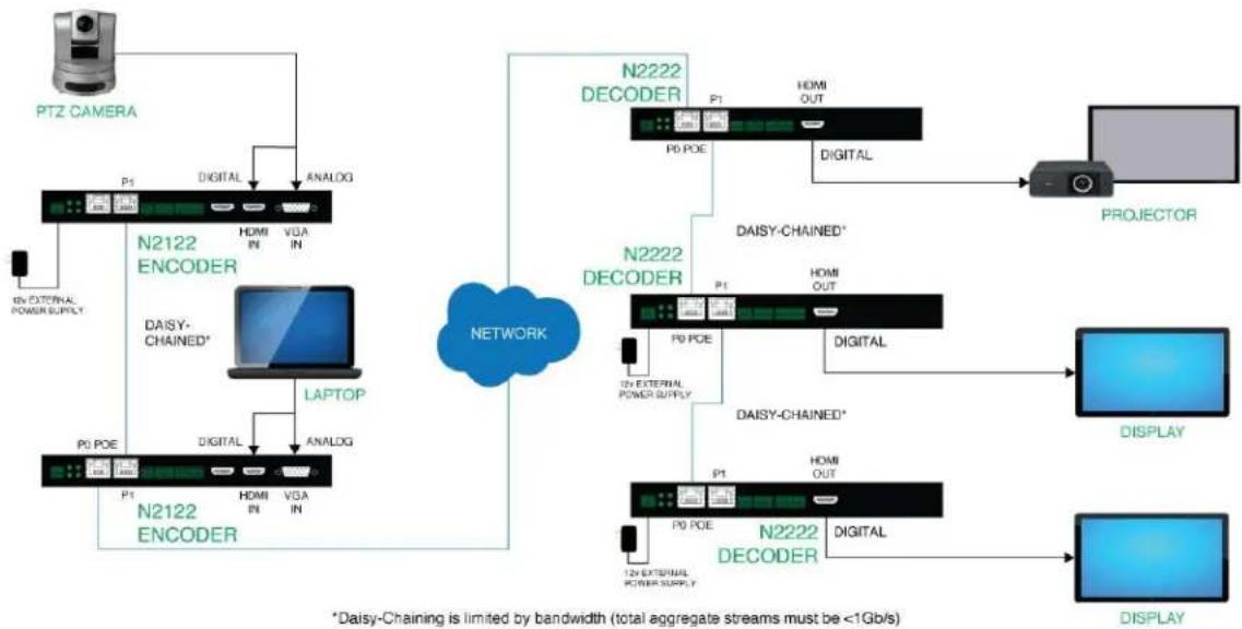
flowchart
graph TD
    A["PTZ CAMERA"] --> B["N2122 ENCODER"]
    B --> C["LAPTOP"]
    C --> D["N2122 ENCODER"]
    D --> E["NETWORK"]
    E --> F["N2222 DECODER"]
    F --> G["PROYECTOR"]
    F --> H["DISPLAY"]
    F --> I["DISPLAY"]
    B --> J["PHO EXTERNAL POWER SUPPLY"]
    B --> K["PHO IN"]
    B --> L["PHO IN"]
    B --> M["PHO IN"]
    B --> N["PHO IN"]
    B --> O["PHO IN"]
    B --> P["PHO IN"]
    B --> Q["PHO IN"]
    B --> R["PHO IN"]
    B --> S["PHO IN"]
    B --> T["PHO IN"]
    B --> U["PHO IN"]
    B --> V["PHO IN"]
    B --> W["PHO IN"]
    B --> X["PHO IN"]
    B --> Y["PHO IN"]
    B --> Z["PHO IN"]
    B --> AA["PHO IN"]
    B --> AB["PHO IN"]
    B --> AC["PHO IN"]
    B --> AD["PHO IN"]
    B --> AE["PHO IN"]
    B --> AF["PHO IN"]
    B --> AG["PHO IN"]
    B --> AH["PHO IN"]
    B --> AI["PHO IN"]
    B --> AJ["PHO IN"]
    B --> AK["PHO IN"]
    B --> AL["PHO IN"]
    B --> AM["PHO IN"]
    B --> AN["PHO IN"]
    B --> AO["PHO IN"]
    B --> AP["PHO IN"]
    B --> AQ["PHO IN"]
    B --> AR["PHO IN"]
    B --> AS["PHO IN"]
    B --> AT["PHO IN"]
    B --> AU["PHO IN"]
    B --> AV["PHO IN"]
    B --> AW["PHO IN"]
    B --> AX["PHO IN"]
    B --> AY["PHO IN"]
    B --> AZ["PHO IN"]
    B --> BA["PHO IN"]
    B --> BB["PHO IN"]
    B --> BC["PHO IN"]
    B --> BD["PHO IN"]
    B --> BE["PHO IN"]
    B --> BF["PHO IN"]
    B --> BG["PHO IN"]
    B --> BH["PHO IN"]
    B --> BI["PHO IN"]
    B --> BJ["PHO IN"]
    B --> BK["PHO IN"]
    B --> BL["PHO IN"]
    B --> BM["PHO IN"]
    B --> BN["PHO IN"]
    B --> BO["PHO IN"]
    B --> BP["PHO IN"]
    B --> BQ["PHO IN"]
    B --> BR["PHO IN"]
    B --> BS["PHO IN"]
    B --> BT["PHO IN"]
    B --> BU["PHO IN"]
    B --> BV["PHO IN"]
    B --> BW["PHO IN"]
    B --> BX["PHO IN"]
    B --> BY["PHO IN"]
    B --> BZ["PHO IN"]
    B --> CA["PHO IN"]
    B --> CB["PHO IN"]
    B --> CC["PHO IN"]
    B --> CD["PHO IN"]
    B --> CE["PHO IN"]
    B --> CF["PHO IN"]
    B --> CG["PHO IN"]
    B --> CH["PHO IN"]
    B --> CI["PHO IN"]
    B --> CJ["PHO IN"]
    B --> CK["PHO IN"]
    B --> CL["PHO IN"]
    B --> CM["PHO IN"]
    B --> CN["PHO IN"]
    B --> CO["PHO IN"]
    B --> CP["PHO IN"]
    B --> CQ["PHO IN"]
    B --> CR["PHO IN"]
    B --> CS["PHO IN"]
    B --> CT["PHO IN"]
    B --> CU["PHO IN"]
    B --> CV["PHO IN"]
    B --> CW["PHO IN"]
    B --> CX["PHO IN"]
    B --> CY["PHO IN"]
    B --> CZ["PHO IN"]
FIG. 11 Basic Networked AV
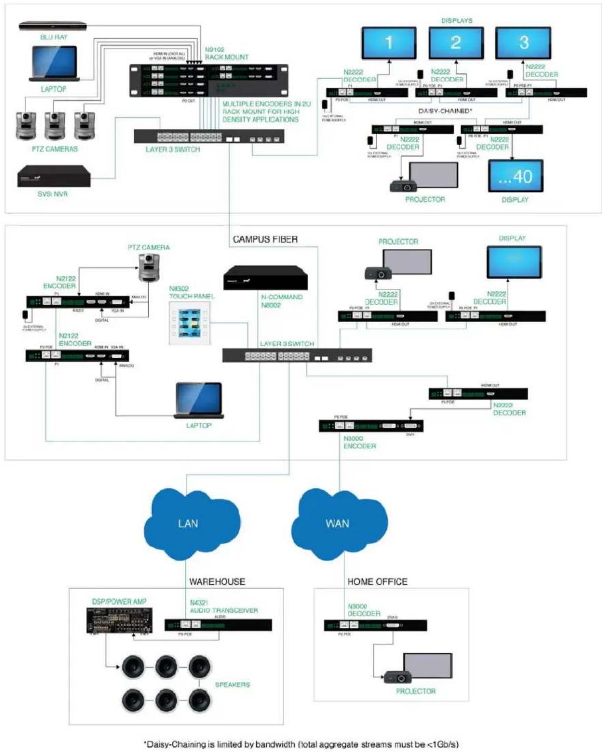
flowchart
graph TD
    subgraph Top_Layer
        A["BLU RAY"] --> B["LAPTOP"]
        B --> C["PTZ CAMERAS"]
        C --> D["SVSI NVR"]
        D --> E["LAYER 3 SWITCH"]
        E --> F["N9102 RACK MOUNT"]
        F --> G["MULTIPLE ENCODERS IN 2U RACK MOUNT FOR HIGH DENSITY APPLICATIONS"]
    end

    subgraph Middle_Layer
        H["DIASY-CHAINED*"] --> I["PROJECTOR"]
        I --> J["DISPLAY"]
        J --> K["...40"]
    end

    subgraph Bottom_Layer
        L["CAMPUS FIBER"] --> M["N-COMMAND N8002"]
        M --> N["LAYER 3 SWITCH"]
        N --> O["LAPTOP"]
        O --> P["PTZ CAMERA"]
        P --> Q["N2122 ENCODER"]
        Q --> R["IN-DIVIDUAL RACK/SUPPLY"]
        R --> S["N8302 TOUCH PANEL"]
        S --> T["Digital"]
        T --> U["N2122 ENCODER"]
    end

    subgraph Bottom_Layer
        V["WAN"] --> W["LAN"]
        W --> X["WAREHOUSE"]
        X --> Y["HOME OFFICE"]
        Y --> Z["DSP/POWER AMP"]
        Z --> AA["SPEAKERS"]
        AA --> AB["Audio TRANSCEVER AUDIO"]
        AB --> AC["DISP/POWER AMP"]
        AC --> AD["N4321 AUDIO TRANSCEVER AUDIO"]
        AD --> AE["PROYECTOR"]
    end

    style Top_Layer fill:#f9f,stroke:#333
    style Middle_Layer fill:#bbf,stroke:#333
    style Bottom_Layer fill:#dfd,stroke:#333
    note right of A: BLU RAY
    note right of B: LAPTOP
    note right of H: DIASY-CHAINED*
    note right of I: PROYECTOR
    note right of J: LAN
    note right of K: WAN
    note right of L: MODE OUT
    note right of M: MODE OUT
    note right of N: MODE OUT
    note right of O: MODE OUT
    note right of P: MODE OUT
    note right of Q: MODE OUT
    note right of R: MODE OUT
    note right of S: MODE OUT
    note right of T: MODE OUT
    note right of U: MODE OUT
    note right of V: MODE OUT
    note right of W: MODE OUT
    note right of X: MODE OUT
    note right of Y: MODE OUT
    note right of Z: MODE OUT
    note right of AA: MODE OUT
    note right of AB: MODE OUT
    note right of AC: MODE OUT
    note right of AD: MODE OUT
    note right of AE: MODE OUT
    note right of AF: MODE OUT
    note right of AG: MODE OUT
    note right of AH: MODE OUT
    note right of AI: MODE OUT
    note right of AJ: MODE OUT
    note right of AK: MODE OUT
    note right of AL: MODE OUT
    note right of AM: MODE OUT
    note right of AN: MODE OUT
    note right of AO: MODE OUT
    note right of AP: MODE OUT
    note right of AQ: MODE OUT
    note right of AR: MODE OUT
    note right of AS: MODE OUT
    note right of AT: MODE OUT
    note right of AU: MODE OUT
    note right of AV: MODE OUT
    note right of AW: MODE OUT
    note right of AX: MODE OUT
    note right of AY: MODE OUT
    note right of AZ: MODE OUT
    note right of BA: MODE OUT
    note right of BB: MODE OUT
    note right of BC: MODE OUT
    note right of BD: MODE OUT
    note right of BE: MODE OUT
    note right of BF: MODE OUT
    note right of BG: MODE OUT
    note right of BH: MODE OUT
    note right of BI: MODE OUT
    note right of BJ: MODE OUT
    note right of BK: MODE OUT
    note right of BLI: MODE OUT
    note right of BMI: MODE OUT
    note right of BNI: MODE OUT
    note right of BOI: MODE OUT
    note right of BPJL: MODE OUT
    note right of BPJLII: MODE OUT
    note right of BPJLIII: MODE OUT
    note right of BPJLIVI: MODE OUT
    note right of BPJLVI: MODE OUT
    note right of BPJLVII: MODE OUT
    note right of BPJLVIII: MODE OUT
FIG. 12 Multi-Switch Enterprise Network
Installing and Configuring Your AV Equipment
This chapter provides an installation overview as well as a detailed step-by-step process for installation. If you encounter any problems, refer to the Troubleshooting section on page 66 for help.
Installation Overview
The N2000 Encoders and Decoders have multiple configuration and installation options. For basic installation guidelines, see the table below. For more detailed instructions, refer to Step-by-Step Installation Instructions on page 16.
| Basic Installation Guidelines | |
| Connections Options | |
| Power | Power over Ethernet (PoE): Connect the unit's P0 port to an active, PoE-enabled network switch (not supported on the N2212 Decoder). |
| External power supply: If not using PoE for power, connect a 12V regulated power supply (part number N9312) to the unit's two-pin terminal block plug connector labeled +12V 2A. Power supply is required for the N2212 Decoder. | |
| Network | PoE units: If using PoE to power the unit, you should already have a network connection. |
| Externally powered units: If not using PoE, connect either the P0 or P1 port to the network using the appropriate cable. | |
| Daisy-chain configuration: Once network connection is established to one unit, you can daisy-chain additional units by connecting Ethernet cables between devices using their P0 and/or P1 ports. Keep in mind that the number of units supported in this configuration is limited by bandwidth (total aggregate streams must be less than 1 Gb/s).NOTE: PoE power is only supplied to the unit connected directly to the network. All other units in the daisy-chain must have an external power supply. | |
| Video N2000 EncodersFor video encoding of a digital source, connect the source to the Encoder's HDMI IN port using a video cable with an HDMI connector (or adapter).For video encoding of an analog source, connect the source to the Encoder's VGA IN port using a video cable with a VGA connector (or component adapter). | |
NOTE: When the unit is not in use, remove the power cable and disconnect any other cables (e.g., Ethernet, audio, video) connected to the Encoders and Decoders.
Mounting Options
The N2000 units are available in stand-alone and card versions. The stand-alone version can be free standing, surface mounted, wall mounted, or rack mounted. All cards must be rack mounted using the N9206 Card Cage (sold separately).
Surface and Wall Mounting
To mount your N2000 stand-alone unit to a flat surface or wall, follow these steps:
- Remove the four screws from the bottom of the unit and use them to attach the mounting wings (not included in shipment - part number N9101). See Figure 1.
- Place the unit against the solid surface to which you want it mounted.
- Using standard hardware, attach the unit through each of the slots of the newly-attached mounting wings.
- Connect the appropriate cables necessary for your application. Refer to the sections: Connecting Decoders to the Network on page 18 and: Connecting Encoders to the Network and Configuring Stream Settings on page 19 for more information on these connections.

natural_image
Pure diagram of a rectangular device with four directional arrows indicating bidirectional flow or movement (no text or symbols)FIG. 1 Installing Mounting Wings
Rack Mounting
N2000 Series Stand-Alone Units
A Rack Shelf (part number N9102) accommodates up to two stand-alone N-Series Encoders or Decoders, side by side (mix and match).

FIG. 2 Rack Mounting Stand-Alone Units
N2000 Series Cards
A Card Cage (part number N9206) accommodates up to six N-Series Encoder/Decoder cards (mix and match). The 12V power supply of the N9206 is the primary power source for the installed cards. If the 12V power supply fails or is unplugged, the cards will power down, detect PoE (if provided by switch) and restart normally using PoE. This usually results in a power loss of about one to two seconds. The unit then reboots (which takes another one to two minutes).
To rack mount N2000 Series cards into the N9206 Card Cage, follow these steps:
- Gently slide the card into cage slot. Make sure the card is properly aligned with guides. The card's front LED indicators should align with holes in the cage's faceplate. See Figure 3.
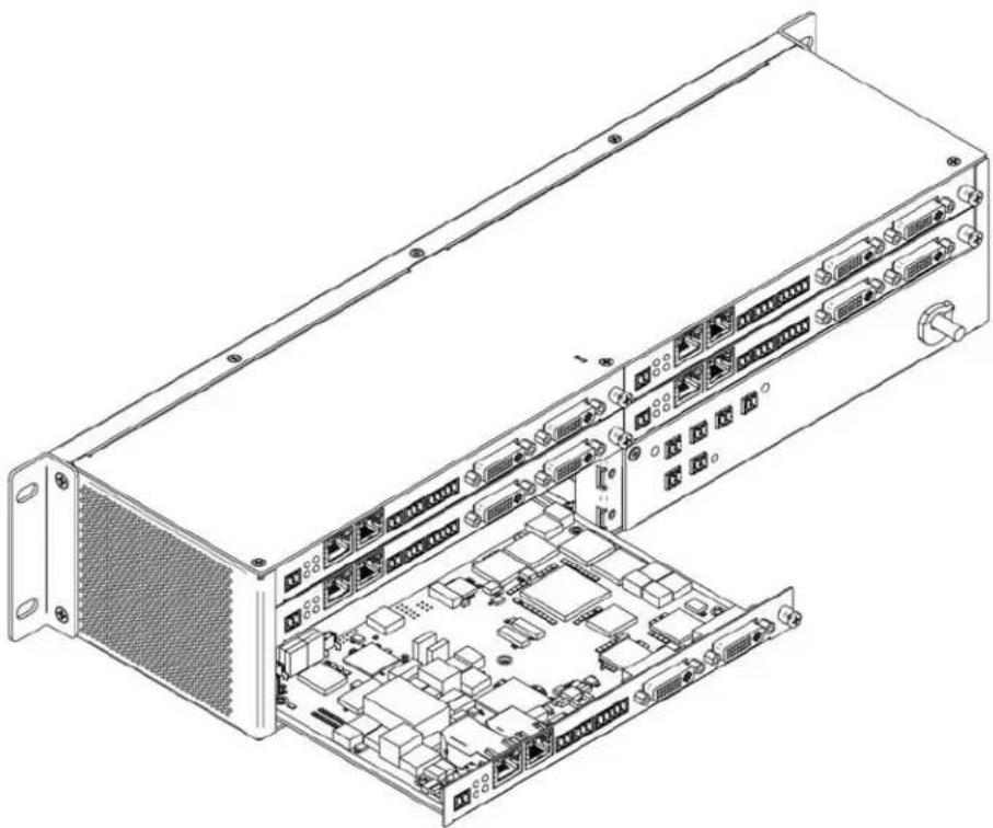
natural_image
Technical line drawing of a server rack with internal components and external wiring (no text or labels)FIG. 3 Rack Mounting Cards
- Align the thumb screw on back plate before seating card into cage.
- Firmly seat the card and tighten the thumb screw by hand to secure card placement.
- Use one of the six Phoenix connector cables (included in shipment with the Card Cage) to connect the card's 12VDC input Phoenix connector to one of the cage's six 12VDC outputs.
- Repeat these steps until all cards are properly installed. See Figure 4.

natural_image
Front view of a rack-mounted server rack with multiple ports and connectors (no visible text or labels)FIG. 4 Fully-Populated Card Cage
- For proper airflow, cover any unused card slots with faceplate blanks. Blanks are sold separately (part number N9210).
- Make sure the Card Cage's power cord is plugged in for proper cooling.
CAUTION: Keep the Card Cage's power cord plugged in at all times so that the internal fans are always running. Not doing so could void the warranty of the cage and all installed cards. Fans are not powered while in backup PoE power mode. Please remedy power losses immediately to avoid potential overheating hazards.
NOTE: Mounting accessories are sold separately and are compatible with most N-Series devices. Contact a sales representative or visit our website for details.
Step-by-Step Installation Instructions
This section provides step-by-step guidance for installing and configuring equipment from the SVSI product family on your network. The steps provided here assume the following to be true:
1. There are PoE switches operational on the network.
SVSI equipment can operate on many different brands of networking equipment. The network itself needs to meet certain requirements to be able to support deployment. These instructions assume that you have purchased and installed a pre-configured switch from SVSI or that your existing equipment meets the following physical and protocol requirements:
- Layer 3, also known as "multi-layer"
• Gigabit Ethernet
• I G M P S n o o p i n g
• IGMP Snooping Querier (which only needs to be enabled on a single switch within the network)
NOTE: To proceed with this installation, the switches must already be successfully connected to your network. If needed, refer to your product's documentation for installation instructions.
2. Deployment considerations have been made for the addition of high-speed video.
Our Networked AV solutions provide unsurpassed video and audio quality at bandwidths appropriate to any network segment or link. Matrix switches as large as 1200x800 have been constructed on a house network using SVSI equipment. Alternatively, many customers choose to deploy on physically separate networks in order to use low-cost network appliances but keep video traffic separate from data and voice.
3. You loaded N-Able onto the computer you are using to configure the equipment.
From your host computer, download N-Able (our free setup utility software):
PC version - http://www.amx.com/products/N-ABLE-PC.asp
Mac version - http://www.amx.com/products/N-ABLE-MAC.asp
This software is designed to set up and control the equipment during initial deployment, however, it is not always the best solution for production-type or primary user control. Refer to Control Options on page 25 for details on the available control options.
Step 1: Setting Up Your Host Computer
In order to communicate with SVSI products, your devices must be on the same subnet as the host computer. N2000 devices are shipped in Auto IP mode with a default IP address of 169.254.xxx.xxx. Before beginning installation, you will need to make some changes to the computer running N-Able. These steps show how this can be accomplished in a Microsoft Windows environment.
- From the Start menu, select Control Panel > Network and Sharing Center.
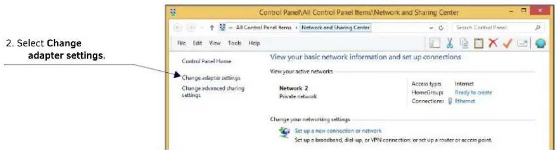
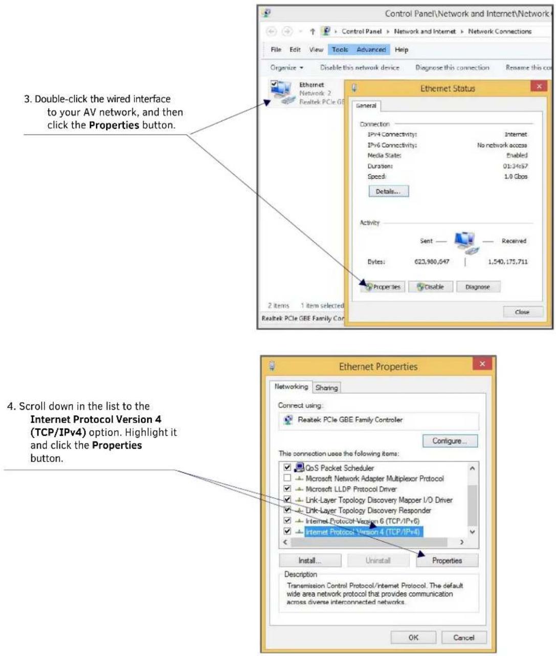

NOTE: If the computer does not need Internet access, you can simply enter a unique 169.254.xxx.xxx IP address with a 255.255.0.0 subnet mask. Contact your network administrator if you are unsure of how to configure the existing network. SVSI units will not self-assign in the 169.254.0.xxx range.
NOTE: If the computer has a statically-assigned IP address, click the Advanced button. Then click Add to enter a unique 169.254.xxx.xxx address with a Subnet Mask of 255.255.0.0 and a Default Gateway of 169.254.1.1.
Step 2: Connecting Decoders to the Network
The digital connection from a Decoder HDMI OUT port (female) to a display is accomplished using either a HDMI cable or DVI-D (through adapter). N2000 units support embedded audio input and output on the HDMI ports; however, some display devices (e.g., many monitors) do not support embedded audio. When using such a display, use the AUDIO port for separate transmission of sound and turn HDMI Audio off (on the Settings page) to avoid video display issues.
Power is supplied via a PoE-enabled switch or an external power supply. The N2212 is not a PoE device and must be powered by an external power supply. Refer to the following steps and Figure 5 for guidance.
- Using a Cat-5 cable, connect your SVSI Decoder's PO port to a PoE-enabled switch. This provides both network and power connection. In non-PoE applications connect a 12V regulated power supply (N9312) to the two-pin terminal block plug connector (labeled +12V 2A).
- Connect the display you would like to use for that Decoder (monitor, projector, etc.) to the Decoder's HDMI OUT port using an HDMI cable (or DVI through adapter). This must be a digital video connection.

flowchart
graph TD
    A["AMX N-Series Local Play"] --> B["N2000 Decoder"]
    B --> C["Cat-5 Cable"]
    C --> D["PoE-Enabled Switch"]
    D --> E["Network"]
    F["HDMI Cable"] --> B
FIG. 5 Decoder Connections
-
Repeat Steps 1 and 2 until all Decoders are installed on the network.
-
Once the Decoders and displays are connected and powered up, the LocalPlay screen appears on the displays.
NOTE: If the LocalPlay screen does not appear, refer to Chapter 5, Troubleshooting for more guidance.
NOTE: In order for the unit to receive PoE, it must be connected to a switch or other equipment that has a PoE PSE (Power Sourcing Equipment) port. The N2212 Decoder is not a PoE device. When using this product, you must also provide power using the 12V external power supply (included in shipment). PoE does not pass through the daisy chain (P1) port.
CAUTION: Do not run wiring that is connected to a PoE PSE port outside of the building where the PSE resides. It is for intra-building use only.
Step 3: Connecting Encoders to the Network and Configuring Stream Settings
- Using a Cat-5 cable, connect your SVSI Encoder's PO port to a PoE-enabled switch. In non-PoE applications connect a 12V regulated power supply (N9312) to the two-pin terminal block plug connector (labeled +12V 2A).
NOTE: In order for the unit to receive PoE, it must be connected to a switch or other equipment that has a PoE PSE port.
- In N-Able, select the Unit Management tab and click the Auto Discover button (if the table has not already populated itself with the installed units). See Figure 6.
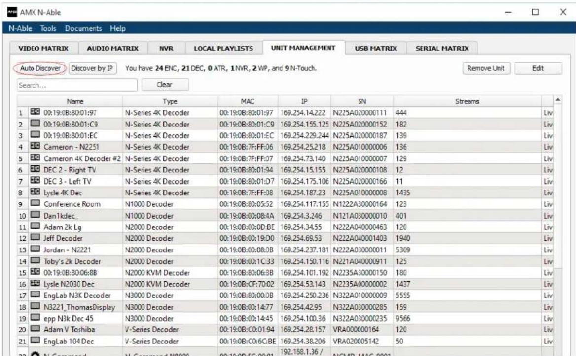
FIG. 6 Unit Management Page
-
Find your Encoder in the list. N2000 units are displayed on the following tabs:
-
Unit Management tab — N2000 units have N2000 Encoder/Decoder listed in their Type fields.
• Video Matrix tab — N2000 units are found on the N2000 sub-tab (as shown in Figure 7).
NOTE: If using multiple Encoders in your set up, it is important to plug in and configure one Encoder at a time. All Encoders come pre-configured to use stream 1. As you add Encoders to the network, you will need to set them up to use different streams.

Red Text - No video source (Encoder) or no display (Decoder).
Black Text - Unit is in live play mode.
Gray Text - Video output for this unit is disabled.
Blue Text - Unit is playing locally-stored content.
FIG. 7 Video Matrix Page
- Double-click the Encoder's name in the list. The N-Series Encoder Login page is displayed (see Figure 8). If prompted, use the following default login credentials to log in for the first time. These can be changed later on the Settings page.
Default username: admin
Default password: password

FIG. 8 Login Page
NOTE: The Login page is only displayed if N-Able's stored username/password does not match the unit's username/password. A default system will match.
- The Settings page is displayed (see Figure 9).
- Change the Stream setting. We recommend setting Stream to a number between 2 and 254 (it is required that the number be less than 32,512).
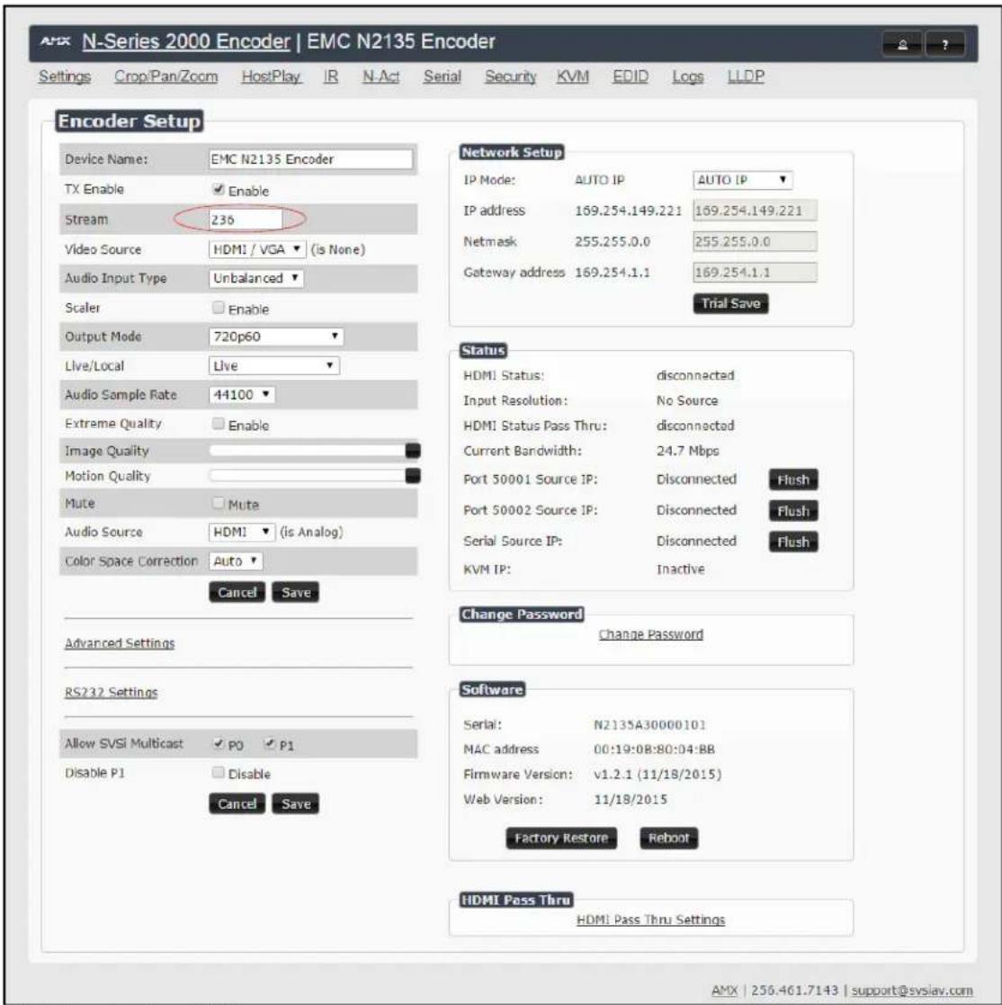
FIG. 9 Changing Stream Setting
- Repeat these steps until all Encoders are connected to the network and configured with an appropriate Stream number.
NOTE: Each Encoder's Stream number must be unique to all other Encoders on the network.
NOTE: Screen-by-screen descriptions of the web interface options are provided for your reference in the Encoder Configuration Options section on page 28 and the Decoder Configuration Options section on page 46.
Step 4: Configuring Decoder and Encoder IP addresses (if needed)
By default, all Decoders and Encoders are preset to Auto IP mode. This means that the IP address is pre-configured to 169.254.xxx.xxx with a subnet mask of 255.255.0.0. When an N2000 is first connected to the network, Auto IP checks the network for available IP addresses in the 169.254.xxx.xxx range and then makes an appropriate, static assignment to each unit. It may be beneficial in some applications to use DHCP (Dynamic Host Control Protocol) or static IP addresses, but IP configuration changes must be done correctly to avoid any communication disruptions with the N2000 unit.
How IP Address Changes Affect Unit Control
As discussed previously, N-Able control is dependent upon the host computer being in the same IP address range as the SVSI devices. Therefore, before making any N2000 IP address changes, we recommend having two statically-assigned IP addresses on your computer.
- Configure the first IP address to be in the range of the default N-Series IP settings (i.e., in the 169.254.xxx.xxx range), AND
- Configure a second IP address in the range of the IP address you are planning to assign to the units (or when using DHCP, an address within the defined range for your network).
Changing IP Addresses
There are two ways to assign new IP addresses to your N2000 units using N-Able:
- Option 1: Log in to each unit individually and make the changes on the Settings page.
- Option 2: Export a comma-separated value (CSV) file, make changes to all units in the resulting file, and import the CSV file into N-Able to apply the changes.
Option 1: Assigning IP Addresses Individually (using the Settings page)
- Find the unit you wish to change in the control matrix (either on the Unit Management tab or the Video Matrix > N2000 tab).
- Double-click the unit and log in.
- Go to the Settings page and make IP address changes for that unit either by setting a STATIC address or by enabling DHCP (see Figure 10).

FIG. 10 Network Setup Section of the Settings Page
-
Click the Trial Save button.
-
Return to the Settings page through the newly-configured IP address.
- Once the Settings page appears (successfully using the new IP address) click the Confirm button to lock in your changes.
NOTE: If you lose communication for any reason, unplug the N2000, wait one minute, and plug it back in. This restores the unit to the original IP address.
Option 2: Assigning IP Addresses to Multiple Units (using CSV files)
N-Able has the ability to export and import CSV files. Once units are auto-discovered in N-Able, the CSV file can be exported into Excel where parameters such as IP address, subnet mask, gateway, stream number, audio settings, etc. can be configured. Once configured, import the CSV file back into N-Able to assign those parameters to the appropriate devices. Reboot the devices to activate the new settings. This procedure can be used to configure multiple networked AV devices at the same time. It can also provide valuable diagnostics by allowing you to see the last known device configuration as well as scan the network for new devices (regardless of IP configuration).
To configure units using a CSV file, follow these steps:
- Make sure that you have performed an Auto Discover (on the Unit Management tab of N-Able) since connecting all of the new units to the network.
- From N-Able's main menu bar, select N-Able > Export CSV.
- Click Yes on the pop-up box informing you that a CSV file is about to be generated.
NOTE: A CSV file editor (e.g., Microsoft Excel) is necessary to proceed.
- The folder containing your CSV file displays. Double-click the file to open it.
- You can use this file to edit the IP mode, IP address, subnet mask, gateway IP address, stream number, etc. Once all changes have been made, save the file.
- Go back into N-Able and select N-Able > Import CSV.
- Browse to your saved CSV file and click Import.
Step 5: Connecting Encoders to an Input Source
Having already connected the Encoder(s) to the network and made the appropriate settings changes (as described in Step 3 and Step 4), you can now connect to the appropriate AV source(s). This connection from an Encoder HDMI IN port (female) to an input source is accomplished using either an HDMI cable or DVI-I (through adapter).
- Connect the source you would like to use for the Encoder (camera, laptop, etc.) to the Encoder's HDMI IN port using an HDMI cable. This connection can be digital or analog.
- Repeat until all Encoders are connected to their sources.

flowchart
graph TD
    A["HDMI Cable"] --> B["N2000 Encoder"]
    B --> C["Cat-5 Cable"]
    C --> D["PoE-Enabled Switch"]
    D --> E["Network"]
FIG. 11 Encoder Connection to Source
Switching and Scaling Options
SVSI Encoders and Decoders make up a true AV matrix solution. In other words, one input can go to any or all outputs. Both Encoders and Decoders have internal scaling capabilities. Keep the following in mind:
- The input of an Encoder is the video and/or audio signal going into the Encoder.
- The output of an Encoder is the network stream.
• The input of a Decoder is the network stream. - The output of a Decoder is the digital video and/or audio being transmitted out to the display device.
Seamless Switching
The N2000 Series supports seamless switching capability if the scalers in the Encoders are all set to the same resolution and refresh rate. If the scalers are off, all of the sources must have the same resolution and refresh rate.
To get streams onto a Decoder, use the Video Matrix tab to route video from an Encoder to a Decoder. This works seamlessly if the previously mentioned settings are true. All you have to do is click the common cell on the matrix, and click the Take button. See Figure 12 for an example.
Enabling this cell causes the Conference Rm Decoder to listen to the Conference Rm Encoder.

FIG. 12 Seamless Switching Using the Video Matrix
Control Options
For the most part, once the initial setup is complete, you will be primarily managing/configuring the Decoders. To better understand, think of Encoders as radio stations and Decoders as car radios. The Encoders are supplying the streams and, using the Decoders, you can "tune in" to the stream you want. SVSI's N-Control solutions (N-Command, N-Act, and N-Touch) provide you with the most flexible management options available, insuring you are getting the most from your digital media system.
Primary Control Options
During initial configuration and setup, the free N-Able setup utility is sufficient. However, we do not recommend N-Able for production-level, primary-user control.
N-Command Controllers
These web-based hardware Controllers offer intuitive, powerful management of equipment, content, NVR recording/playback, bandwidth utilization, and AV switching (using a web-based, point-and-click graphical matrix). The N-Command product line also offers:
- Simplified ASCII interface for third-party control via TCP/IP.
- N8002 and N8012 controllers have master/client failover protection.
- N8012 controller has hot-swappable drives and redundant power supplies.
• Graphical presentation of video network connections. - Full configuration control: assign fixed IP addresses for each SVSI component, adjust variable bit-rate for each video stream, etc.
- Additional software bundles (free with N-Command) allow you to easily create attractive touch panels for N-Series and third-party equipment control, as well as build software design walls of any size. Visit our website for more details on the available N-Command Controllers.
Third-Party Controllers
The N2000 Series is capable of interfacing with third-party control systems such as Crestron. For direct control of N2000 units from any Third Party Control system, please use the Direct Control API (available on our website).
N-Act | On-Board, Built-In Control
All N-Series Encoders and Decoders have on-board, built-in control capability via events that can trigger any number of TCP/UDP commands to other IP controllable devices. Included free with all N-Series Encoders/Decoders. See the section N-Act Page on page 41 for more information.
N-Touch | IP Wall Controller
This 240 x 320 capacitive touch display has Wi-Fi and Bluetooth for expanding control to mobile devices. Programming is done individually through the built-in web server or collectively to multiple units using an N-Command N8000 Series Controller. Multi-page custom graphics can be created using the free Panel Builder software (stored internally).
KVM Configuration
The N2135 Encoders and N2235 Decoders are KVM-capable. By default, USB connections are enabled and configured to follow video switching.
Basic Setup
Follow these steps for basic KVM configuration:
- On the N2135 Encoder, connect the USB Mini-B port to the computer to be controlled.
- Connect the computer's video output to the Encoder's HDMI IN port.
- On the N2235 Decoder, connect the HDMI OUT to the display.
- Connect a USB keyboard and mouse to the Decoder's USB Standard-A ports (they can be plugged into either port).
NOTE: For wireless devices, simply plug the wireless signal receivers into these ports. For keyboard and mouse combos (with a single connection) use the keyboard port.
-
Using N-Able, click the Unit Management tab.
-
Click the Auto Discover button to discover your new devices (if you have not already done so).
- Once discovery is complete (and you see the new units listed in N-Able), click the Video Matrix tab.
- On the matrix, click the common cell for the desired Encoder/Decoder streaming combination.
- Click the Take button to make the change to your matrix. The radio button turns green to indicate the connection was successful.
WARNING: You must assign KVM passwords to your Encoders and Decoders (as well as change the default login password from admin/password) in order for your system to be secure.
Video/USB Switching Options
USB Follows Video: By default, units can be switched using N-Able without modifying the configuration. When you switch video streams (using the matrix) the USB functionality will follow the video.
Independent USB Switching: Use N-Able's USB Matrix tab to switch USB control (without affecting video).
Independent Video Switching: To switch video streams without affecting USB control, first select N-Able > Settings from N-Able's main menu. When the N-Able Settings dialog box is displayed, disable the USB follows Video switching for KVM units. Now you can use the Video Matrix to switch video streams only.
Advanced KVM Functionality: To have the ability to use KVM hotkeys for switching, KVM Advanced Settings must be enabled on the individual unit (select KVM from the top of the unit's web interface). The next section discusses these settings in more detail.
Advanced KVM Setup (With Added Security Features)
You can configure devices for more advanced KVM operation on the Encoder and Decoder using N-Able's KVM Wizard. To access the wizard, select Tools > KVM Wizard from the N-Able main menu (as shown below in Figure 13).
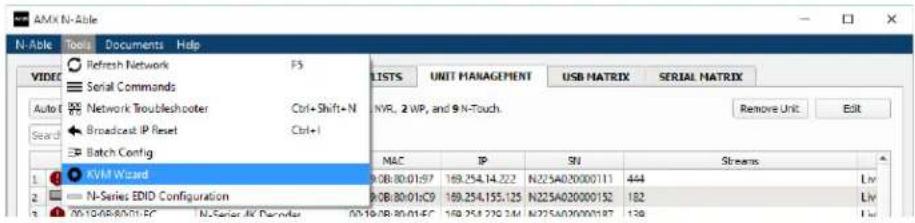
FIG. 13 KVM Wizard
The following table describes some of the more advanced functionality.
| Hotkeys, Passwords, and Permission Levels | |
| Option Description | |
| Permission Levels | Determines which Decoders can communicate with which Encoders. A Decoder must have a permission level that is equal to or greater than the Encoder in order for communication to be successful. |
| KVM Encoders table | Use the KVM Encoders table (on the Decoder's KVM page) to:Let the Decoder know the Encoder passwords it needs to establish communication.Assign Encoder hotkeys.Add/remove Encoders from the Decoder's list. |
| Passwords | By default, KVM streams are encrypted with a common password. You can change the password on the Settings page of the Encoder. If you change Encoder passwords, you will need to supply the new information to the Decoders to allow communication to continue.A Decoder only receives password Information for the Encoders on the network that have been associated with that Decoder as mentioned previously. |
| Hotkeys | To use hotkeys for easy switching, enable KVM Directory Screen Enable on the Decoder's KVM page. You can now access the KVM Directory Screen at any time by pressing thebutton twice on the keyboard connected to the Decoder. This screen displays all Encoders associated with that Decoder (and their corresponding hotkey). |
| Import and export KVM CSV files | Multiple Encoders and Decoders can be configured from a single CSV file (which is generated using the KVM Wizard in N-Able). Once all changes are made, upload the file to each unit using its KVM page.Click the Choose File button, browse to the CSV file you exported from the wizard, and click the Upload button. |
NOTE: These options can also be managed in the unit's GUI (by clicking KVM from the main menu as shown in Figure 14). It is important to note that many of these options only appear on the KVM page when USB is enabled as well as KVM Advanced Settings. See KVM Page on page 61 for more details.

FIG. 14 Selecting the KVM Page
Encoder Configuration Options
This chapter defines N2000 Series Encoder configuration options. For ease of navigation, it is organized to reflect the graphical user interface (GUI).
From any main page in the GUI, you can access all other main pages by clicking the links in the top navigation bar. Figure 1 shows the navigation bar and provides hot links to the sections of this chapter which describe each main page.

FIG. 1 Section Links
Settings Page
Click the Settings link at the top of any of the main web pages to access the page shown in Figure 2. This page is divided into several sections and also has links to other dialog boxes for additional configuration options. Refer to the following sections for detailed descriptions:
• Encoder Setup Section on page 30
• Advanced Settings on page 32
• RS232 Settings on page 34
• Network Setup Section on page 34
• Status Section on page 35
• Change Password on page 36
• Software Section on page 36
• HDMI Pass Thru Settings on page 37

FIG. 2 Settings Page
Encoder Setup Section
The Encoder Setup section of the Settings page is shown in Figure 3. Options are described in Table 1.

FIG. 3 Encoder Setup Section
TABLE 1 Settings Page: Encoder Setup Section
| Option Description Notes | ||
| Device Name | Enter a user-friendly name for the unit. | More descriptive names in this field help you organize and manage the SVSI system efficiently. Names based on the unit's location and function are very useful. Some good examples areLobby-Left-VGA(for left side of lobby, VGA input) orCR201-HDMI(for Conference Room 201, HDMI input). Keep in mind the matrices are organized alphanumerically. |
| TX Enable Enable to broadcast the AV signals. Disable to turn off/stop broadcasting. | ||
| Stream | View/edit the current transmit stream number. | To better understand this setting, think of Encoders more like a channel on a cable box, rather than a traditional AV Matrix. Each Encoder must have a unique stream number, Just like every channel must have a unique channel number (e.g., Food Network and HGTV cannot both be on channel 201). |
| Audio Input Type | SelectUnbalanced(single-ended) orBalancedanalog audio Input. | |
| Video Source | Select which Input port is encoding video. | SelectingHDMI/VGAdeclares HDMI as the primary port and VGA as the secondary port (when there is no HDMI Input). SelectingVGA onlyorHDMI onlydisables the other video input port. |
| Scaler | Enable to scale outgoing content to a fixed resolution or to use theCrop/Pan/Zoomfunctions. | |
| Option | Description | Notes |
| Output Mode Select | the output resolution of the video to be transmitted onto the network (the Scaler check box must be enabled for this to be applicable). | |
| Live/Local Select live | video or locally stored images for transmission onto the network. When video is not available, it automatically goes into local mode. | When video is not available, the most recently played local playlist is displayed. |
| Audio Sample Rate Select | ect the sample rate, In Hz, for the analog audio. | |
| Extreme Quality Enable | this check box to achieve best possible picture quality. | Enabling this option will increase your bandwidth, up to 200 Mbps per stream. Plan bandwidth accordingly. Enabling this option increases video quality only in situations where there are dense lines or dramatic color variations (e.g., a dense map or fully-populated spreadsheet). Can be disabled for most applications. |
| Image Quality Adjust | the compression level of the image. The further to the left on the slider, the more compression which will display as pixelization of the Image. | When Extreme Quality is enabled, this slider's settings are not applied. |
| Motion Quality Adjust | the frame rate reduction. All the way to the right of the slider is 60 frames. As you slide left, you reduce frame rates. | The quickest way to reduce overall bandwidth is to reduce motion quality. However, this increases latency. |
| Mute Enable to stop the transmission of audio data onto the network. | ||
| Audio Source Set the audio source to be disabled, enabled or selected automatically (see note). | The AUTO setting always corresponds to HDMI audio as long as there is an HDMI source. If the source is unplugged, it will automatically fall back to analog audio (if there is an analog source plugged in). | |
| Color Space Correction Set the color space settings for the Encoder (YcbCr, RGB) to be disabled, enabled, or selected automatically based on the source. | If you see a pink/green washed out screen (across the entire image), this can be changed by modifying color space settings. Most sources function with Auto selected but (for problematic sources) hard-set the value to what the source requires. It is best to do hard-set for all permanently installed sources (e.g., cameras, cable boxes, etc), but leave Auto on for periodic sources (e.g., laptop inputs). | |
| Advanced Settings | Refer to Advanced Settings on page 32 for details on the options available from this link. | |
| RS232 Settings | Refer to RS232 Settings on page 34 for details on the options available from this link. | |
| Allow SVSI Multicast Disable this option to prevent the port from outputting multicast video traffic. | Particularly useful if you are connecting a non-SVSI device to a port for network-based control. | |
| Disable P1 | Completely disables the P1 port for all traffic. | Once disabled, anything connected to the P1 port will no longer be available on the network. |
| Cancel | Click to return all controls to the last saved configuration. | |
| Save | Click to accept changes made to these controls. | |
Advanced Settings
The section of the Settings page shown in Figure 4 is displayed when you click the Advanced Settings link. Options are described in Table 2.

FIG. 4 Advanced Settings
TABLE 2 Settings Page: Advanced Settings
| Option Description Notes | ||
| Settings Lock Enable to lock the Encoder IP settings and stream number, preventing automated processes (from N-Able or N-Command) from occurring. | This does not prevent a control system from making changes or a user from manually making changes. | |
| Input Level Gain Left/Right | Select a PRE-ENCODE cut in the audio signal. This can help prevent distortion of the audio when the source is providing audio that is too loud/clipping.Setting does not affect digital audio. | |
| Audio Gain Slide right to provide a POST-ENCODE boost in the audio signal (to both left and right channels). | This can help compensate when the source is providing a weak audio signal. Does not affect digital audio. | |
| Option | Description | Notes |
| Audio Gain Left/Right Slide right to provide a POST-ENCODE boost in the left or right channel's audio signal. | This can help compensate when the source is providing a weak audio signal. Does not affect digital audio. | |
| Brightness Use sliders to raise or lower RGB values of the Encoder (POST-ENCODE). | Only affects analog video. Does not affect digital video. | |
| Horz Offset Enter the number of pixels to shift the screen to the left. Range is -4 to 4 pixels. | The higher the number, the more to the left the screen will shift. Enter even numbers only to prevent red/blue color swapping. | |
| Vert Offset Enter the number of pixels to shift the screen up and down. Range is -100 to 100 pixels. | The higher the number, the higher the screen will shift. | |
| Gen1 Output Mode | Enable when outputting to V-Series decoders. | |
| Component Sync Window | Use this slider to configure the sync on green sensitivity. | Used for computer video input to help with screen flickering. |
| Input audio for HostPlay | Enable to activate the input audio when the Live/Local menu is set to one of the local images. | |
| HostPlay for Unsupported | Enable to cause the Encoder to use a custom image whenever an unsupported video mode is supplied to it. | |
| Gratuitous ARP Enable the Encoder to send a periodic Address Resolution Protocol (ARP) packet to the network. | ||
| ARP Interval (secs) Determine how often (in seconds) the unit transmits gratuitous ARP packets. | ||
| Unsolicited Status Enable the Encoder to send a periodic status packet to the Send Status Address described below. | ||
| Send Status Address | When Unsolicited Status is enabled, the Encoder sends a periodic status packet to the IP address specified here. | |
| Status Interval (secs) Determine how often (in seconds) the unit transmits status packets. | ||
| Discovery Packet Transmit | Enable the SVSI multicast discovery service (which is used to identify units). | This is useful for larger network integrations when broadcast packets will not cover the entire network. Enabled by default. |
| Discovery Interval (secs) | Determine how often (in seconds) the unit transmits discovery packets. | |
| TTL | Select the Time To Live (TTL) for the transmit audio and video streams. | Limits the lifespan of data on the transmit audio and video streams (to improve performance). |
| VLAN Tagging | When enabled, tags the video and audio IP packet with the VLAN number. | |
| VLAN # | Enter the VLAN number. | This number will be included in the video and audio IP packet when VLAN Tagging is enabled. |
| DSCP # | Select the Differentiated Services Code Point (DSCP) for the transmit audio and video streams. | |
| Serial Master Enable | Enable this device to be the master to the designated client. | |
| Serial Client Address | Enter the IP address of the serial client device. | |
| IR Command Holdoff | Set the delay between IR command portions. The default setting is 25 ms. | IR commands are sent in two parts. This setting is the time (in milliseconds) between transmission of part one and part two. The second part of the command is inverted for confirmation purposes. |
| IR Repeat Holdoff | Set the repeat delay between IR commands. The default setting is 90 ms. | This is the amount of time before a new command is sent. For example, when pressing and holding the volume button on a remote control, this is how long until the command is repeated. |
| N2122 Compatibility Mode | Enable to cause an N2135 Encoder to compress video exactly like an N2121/N2122 Encoder (ensuring matching timing, quality and bandwidth). | This setting only applies to the N2135. |
| Maintain Aspect Ratio | When scalers are enabled, enabling this check box maintains the source's aspect ratio. | |
| Option Description Notes | ||
| Enable SNMP Enable | to allow the device to handle Simple Network Management Protocol (SNMP) queries. | |
| Relaxed Analog Input Timing | Enable to allow small variances in the analog Input (to avoid video interruption). | |
RS232 Settings
The section of the Settings page shown in Figure 5 is displayed when you click the RS232 Settings link. Options are described in Table 3.

FIG. 5 RS232 Settings
TABLE 3 Settings Page: RS232 Settings
| Option Description | |
| RS232 Baud Rate | Select the appropriate baud rate for the RS232 serial interface. Default is 9600. |
| RS232 Data Bits | Select the appropriate data bit count for the RS232 serial interface. Default is 8. |
| RS232 Parity | Select the appropriate parity for the RS232 serial interface. Default is no parity (none). |
| RS232 Stop Bits | Select the appropriate number of stop bits for the RS232 serial interface. Default is 1. |
Network Setup Section
The Network Setup section of the Settings page is shown in Figure 6. Options are described in Table 4.

FIG. 6 Network Setup Section
TABLE 4 Settings Page: Network Setup Settings
| Option Description Notes | ||
| IP Mode | Configure the IP address mode. When set to AUTO IP, an IP Address in the range of 169.254.xxx.xxx with Netmask of 255.255.0.0 and Gateway address of 169.254.1.1 will be automatically assigned to the N2000 Encoder by the control software. When set to DHCP, an IP Address in the range of the DHCP server on the network will be automatically assigned to the N2000 Encoder. When set to STATIC, an IP address, Netmask, and Gateway address must be manually entered. | Using DHCP is generally not recommended. If the device is set to DHCP and falls to receive an address from the DHCP server in time, it will revert back to the AUTO IP Address (169.254.xxx.xxx) until the unit is rebooted. |
| IP address | View the current IP address of the N2000 Encoder. When in STATIC mode, enter a new IP address into this field. | |
| Netmask | View the currentNetmaskof the N2000 Encoder. When inSTATICmode, enter a newNetmaskinto this field. | |
| Gateway address | View the currentGateway addressof the N2000 Encoder. When inSTATICmode, enter a newGateway addressinto this field. | |
| Trial Save Click to | initially save IP address changes. Once you log In to the unit using the new address, you will be able to confirm and accept the changes permanently. | |
Status Section
The Status section of the Settings page is shown in Figure 7. Options are described in Table 5.

FIG. 7 Status Section
TABLE 5 Settings Page: Status Section
| Option Description Notes | ||
| HDMI Status Indicates if a video source is connected to the Encoder. | ||
| Input Resolution Indicates the video resolution of the currently connected source. | ||
| HDMI Status Pass Thru | Indicates if a display device is connected to the Encoder. | |
| Current Bandwidth | This is a snapshot of the unit as properties were loaded to the browser, not a live counter. Refresh the page to get an updated bandwidth. | |
| Port 50001 Source IP | Shows the IP address of the currently connected device or displays Disconnected if no connection exists. | Port 50001 can only accept a single external connection at a time. If a device is currently showing the port occupied (by a control system or other device), then other connections will be rejected. However, connection attempts from the same IP will override the current connection. |
| Port 50002 Source IP | Shows the IP address of the currently connected device or displays Disconnected if no connection exists. | Port 50002 can only accept a single external connection at a time. If a device is currently showing the port occupied (by a control system or other device), then other connections will be rejected. However, connection attempts from the same IP will override the current connection. |
| Serial Source IP Shows the IP address of the currently connected device or displays Disconnected if no connection exists. | Only a single external connection can be accepted on the port. If a device is currently showing the port occupied (by a control system or other device), then other connections will be rejected. However, connection attempts from the same IP will override the current connection. | |
| Flush buttons | These buttons reset the port. | |
| KVM IP | Shows the IP address of the KVM Decoder currently connected to this Encoder. | This setting only applies to the N2135. |
Change Password
To change the N2000 Encoder interface password, enter the current password in the field labeled Old Password, and enter a new password in the New Password and Confirm Password fields. Click Change PW to accept the new password.

FIG. 8 Change Password
NOTE: This password needs to match N-Able's stored password to allow auto-login using N-Able.
Software Section
The Software section of the Settings page is shown in Figure 9. Options are described in Table 6.
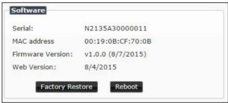
FIG. 9 Software Section
TABLE 6 Settings Page: Software Section
| Option Description | |
| Serial Displays the serial number of the N2000 Encoder. | |
| MAC Address Displays the MAC address of the network interface of the N2000 Encoder. | |
| Firmware Version | Displays the date code for the currently running version of the N2000 Encoder internal firmware. |
| Web Version | Displays the date code for the currently running version of the web interface. |
| Factory Restore | Click to restore the device to the original factory settings. This resets everything except the IP address (including name, stream number, serial settings, etc.). |
| Reboot Click to reboot the device (does not affect current configuration). | |
HDMI Pass Thru Settings
The section of the Settings page show in Figure 10 is displayed when you click the HDMI Pass Thru Settings link. Options are described in Table 7.

FIG. 10 HDMI Pass Thru Settings
TABLE 7 Settings Page: HDMI Pass Thru Settings
| Option Description | |
| HDMI Pass Thru Enables looped output. | |
| Enable HDMI Audio | Determines if the unit will output audio over the HDMI connection. Selecting Auto bases audio output on the settings of the connected source device. |
| YCbCr 4:2:2 Output | For color conversion. Can force to RGB output based on connected device's reported settings. Default (and preferred setting) is Off. |
| Simplified HDMI Detect | When enabled, detects HDMI solely based on the hot plug detection. Enable to help prevent displays/monitors from going to sleep. |
| Invert HDMI Sync | Inverts horizontal and vertical synchronization to the output display. Used for non-standard displays. |
| Cancel Click to return all controls to the last saved configuration. | |
| Save Click to accept changes made to these controls. | |
Crop/Pan/Zoom Page
Click the Crop/Pan/Zoom link at the top of any of the main web pages to access the page shown in Figure 11. This page allows you to customize the viewable portion of the input. See Table8 for option descriptions.

FIG. 11 Crop/Pan/Zoom Page
NOTE: The Scaler check box must be enabled for changes on this page to take effect. See the Settings Page: Encoder Setup Section table on page 30 for more information.
TABLE 8 Crop/Pan/Zoom Page Options
| Option Description | |
| X1, Y1 Set pixel | coordinates of viewing area (top left). |
| X2, Y2 Set pixel | coordinates of viewing area (bottom right). |
| 16:9 Aspect Ratio Enable to force to a 16:9 ratio. | |
| No Crop | Click to disable existing crop settings and return unit to default output settings. |
| Execute Crop Reference | Click to execute changes. |
| Save Crop Reference | Click to save the current settings and store them as a preset for later use. Presets can be used by third-party controllers. |
| Stored Crop Presets | Use this section of the page to select/delete/export/import cropping presets. |
HostPlay Page
Click the HostPlay link at the top of any of the main web pages to access the page shown in Figure 12. This page allows you to upload new images to the Encoders and configure the image playlists. The playlist will be shown on the display when no video is being transmitted or received. You can show a single image or set up multiple images to be displayed at a customized animation rate. Audio can be uploaded and set to play whenever HostPlay is active. See Table 9 for option descriptions.

FIG. 12 HostPlay Page
TABLE 9 HostPlay Page Options
| Option Description | |
| Edit Playlist | Select a playlist from the drop-down menu to view/edit the images currently used in the chosen image playlists. If more than one image appears in the list, a transition time can be set for each image. |
| Save Click to save the current configuration. | |
| Name Enter a name for the playlist. | |
| Output Mode | Select the HostPlay output resolution. The playlists that were uploaded In that resolution are then displayed for your selection. |
| Audio Choose an audio file to play while the HostPlay image is on the screen. | |
| Image list | Allows you to customize what images are displayed, the transition time for each image, etc. |
| Additional Screens | Allows you to choose what is displayed as the HostPlay page if there is an unsupported mode or content protection issue. |
| Image/Audio DB | This section provides the ability to upload image and audio files to the N2000 Encoder database. You can also use the Fill field to customize the background color (used behind HostPlay images that do not take up the entire screen). |
| Delete Images Delete | the selected image file from the playlist. |
| Delete Audio Delete | the selected audio file from the playlist. |
IR Page
Click the IR link at the top of any of the main web pages to access the page shown in Figure 13. This page allows you to upload and execute IR Pronto codes so that other vendor's devices can be controlled through the Encoder's IR connector. Commands can be saved for future use and executed later. The IR Code menu lists all saved IR commands. See Table 10 for option descriptions.
![N-Series 2000 Encoder | ConferenceRm1 - Encoder Settings Crop/Pan/Zoom HostPlay IR N-Act Serial Security KVM EDID Logs LLDP N-Series IR Database IR Code: [New] Save Delete Execute AMX | 256.461.7143 | support@svslay.com](/content/2026/05/1063675/images/7fba89a840394b676608e1082bead590e4d3abac00b90a34d83ef93d780af3ad.jpg)
FIG. 13 IR Page
TABLE 10 IR Page Options
| Option Description | |
| IR Code | Create/select IR codes. Different vendors have different IR Pronto codes and can usually be found through a web search. Copy/paste new IR commands directly into the input space. |
| Save Save the current code. | |
| Delete Delete the current code. | |
| Execute | Activate the selected code through the Encoder's IR connector. |
N-Act Page
Click the N-Act link at the top of any of the main web pages to access the page shown in Figure 14. This page allows you to create command lists which are performed automatically by the unit based on power or video connection (without the use of an outside controller). For example, you can tell a projector and lights to come on when the Encoder powers up. You can add multiple commands for each event. See Table 11____ for option descriptions.

FIG. 14 N-Act Page
TABLE 11 N-Act Page Options
| Option Description | |
| Enable N-Act Events Enable to activate the configured events. | |
| Power on Event | Create/delete/test events to be performed when the Encoder powers on. Visit our website for more details on Application Programming Interface (API) commands. |
| Video Cable Connected Event | Create/delete/test events to be performed when the Encoder is connected to a video source. The Trigger Delay field specifies how long the device has to be connected for the command to be executed. |
| Video Cable Disconnected Event | Create/delete/test events to be performed when the Encoder is disconnected from a video source. The Trigger Delay field specifies how long the device has to be disconnected for the command to be executed. This keeps accidental (momentary) disconnects from triggering the command sequence. |
| Save Events Click to save changes made to this page. | |
| Import/Export | Use this section of the page to import/export N-Act event configurations. from one unit to others. |
Serial Page
Click the Serial link at the top of any of the main web pages to access the page shown in Figure 15. This page allows you to upload and execute commands used for direct control of serial devices. Commands may be saved for future use and executed later. The Serial Code menu lists all saved commands. See Table 12 for option descriptions.
NOTE: If the Port 5004/Serial Port is currently in use by another device, sending commands from the Serial page will always return a No Data message and fail to send the commands.
![N-Series 2000 Encoder | ConferenceRm1 - Encoder Settings Crop/Pan/Zoom HostPlay IR N-Act Serial Security KVM EDID Logs LLDP N-Series Serial Database Serial Code: [New] Save Delete Execute ASCII: HEX: Response: AMX | 256.461.7143 | support@sysiav.com](/content/2026/05/1063675/images/6c0ab6975f16320fc3fc8babc27f3c75aec294923677696ff2d85f2d85ee34f8.jpg)
FIG. 15 Serial Page
TABLE 12 Serial Page Options
| Option Description | |
| Serial Code | Create/select serial commands. Different vendors have different codes that can usually be found through a web search. Copy/paste new commands (in either ASCII or HEX) directly into the appropriate input space. |
| Save Save the current code. | |
| Delete Delete the current code. | |
| Execute Apply the selected code to the Encoder's serial connection. | |
| ASCII and HEX | Paste serial commands directly into either the ASCII or HEX field. |
| Response | View responses provided by the device receiving the serial command(s). |
Security Page
Click the Security link at the top of any of the main web pages to access the page shown in Figure 16. This page allows you to force HTTPS connections and set up a default password for stream encryption. To successfully communicate, the Decoder must know and match the Encoder password.

FIG. 16 Security Page
KVM Page
Click the KVM link at the top of any of the main web pages to access the N-Series KVM page. You must check the USB Enable box at the top to see the page shown in Figure 17. See Table 13 for option descriptions. This page applies to KVM units only (N2135 Encoder and N2235 Decoder).

FIG. 17 KVM Page
TABLE 13 KVM Page Options
| Option Description | |
| USB Enable | Enable to allow the ability to share mouse and keyboard over the network. Enabled by default. When disabled, the unit works like a non-KVM unit and ignores any keyboard or mouse activity. |
| Multiaccess | Enable to allow multiple Decoders to access this Encoder at the same time. (maximum is 100 connections). See the section Advanced KVM Setup (With Added Security Features) on page 27 for more information. |
| Permission Level | Set the permission level for the Encoder. Decoders can only establish USB connection to Encoders with the same or higher permission level. See the section Advanced KVM Setup (With Added Security Features) on page 27 for more information. |
| Import KVM CSV | Click the Choose File button and browse to the KVM CSV file on your computer that you would like to use to configure the unit. Then click Upload. For more information, see the section Advanced KVM Setup (With Added Security Features) on page 27. |
| Export KVM CSV | Click the Download KVM CSV Export link to retrieve the current KVM CSV configuration file. |
| Reset USB and KVM Settings | Resets all USB and KVM settings. |
EDID Page
Click the EDID link at the top of any of the main web pages to access the page shown in Figure 18. Every display has stored information that it communicates to the output device. This page allows you to view that information. Options are described in Table 14 . Edit the Encoder's EDID if you need to change the display options available to the source. There are four different ways to control the EDID of the Encoders.
Option 1: Use the default settings drop-down menu and select from the options available. Then click Set EDID. This will work for most sources and is most often set to Stereo (2 channel).
Option 2: When using an EDID captured from a display connected to a Decoder, paste the data in to the white EDID block, overwriting existing EDID. Then click Set EDID.
Option 3: Make changes to the operating parameters displayed on the right side of the screen. Use the Encode button to translate the changes into a new EDID and click Set EDID.
Option 4: Connect a compatible display to the Encoder's HDMI Out port and click Set EDID to Pass-thru.
NOTE: The source will need to be disconnected while modifying EDID settings.

FIG. 18 EDID Page
TABLE 14 EDID Page Options
| Option Description | |
| EDID drop-down box Select what EDID information to display.Pass-thru: Displays EDID information for the display connected to the Encoder's pass thru port.Local (Digital/Analog): Displays EDID information for the Encoder. This information is being provided to the source connected to the Encoder. | |
| Decode button | Click to translate the EDID currently displayed on the left to the operating parameters list on the right. |
| Encode button | After making any changes to the operating parameters list on the right, click this button to update the EDID information on the left. To store the new settings, click Set EDID. |
| Read EDID | Click to initially show the EDID or if the source EDID has changed (refreshes the EDID table). |
| Set EDID If creating a custom EDID, click to apply the changes. | |
| Set EDID to Pass-thru | Set the EDID to the pass-thru EDID of the connected display to HDMI OUT. |
| Reset EDID | For Digital, choose a standard EDID from the drop-down menu and click Reset EDID to apply. For Analog, no selection is necessary. |
Logs Page
Click the Logs link at the top of any of the main web pages to access the page shown in Figure 19. The Logs page displays a command log that lists all TCP and UDP messages the unit receives. It also displays the web browser's IP address and gives you options to Refresh and Reset Logs.

FIG. 19 Logs Page
LLDP Page
Click the LLDP link at the top of any of the main web pages to access the page shown in Figure 20. The LLDP page displays information from the Link Layer Discover Protocol (LLDP) packet which identifies the port number and switch the device is connected to.

FIG. 20 LLDP Page
Decoder Configuration Options
This chapter defines N2000 Series Decoder configuration options. For ease of navigation, it is organized to reflect the graphical user interface (GUI).
As explained previously, you can access the GUI main pages by clicking the links in the top navigation bar. Figure 1 shows the navigation bar and provides hot links to the sections of this chapter which describe each main page.
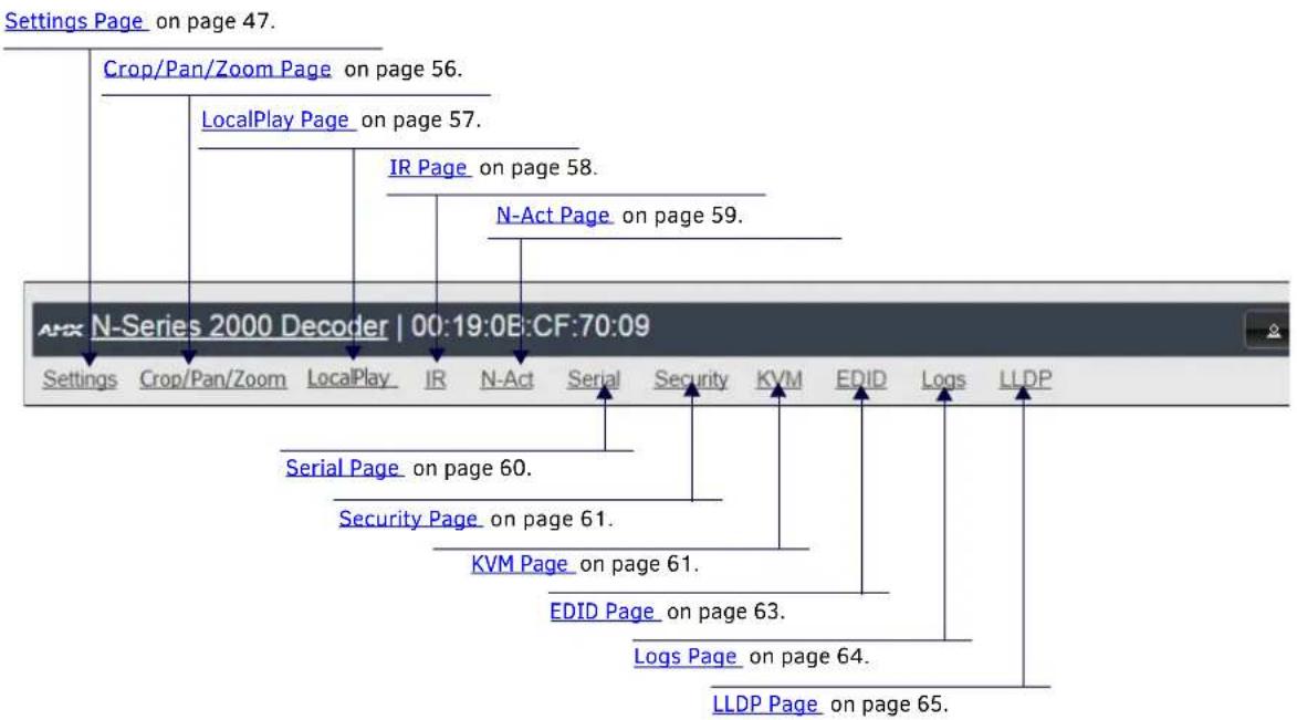
FIG. 1 Section Links
Settings Page
Click the Settings link at the top of any of the main web pages to access the page shown in Figure 2. This page is divided into several sections and also has links to other dialog boxes for additional configuration options. Refer to the following sections for detailed descriptions:
• Decoder Setup Section on page 48
• Advanced Settings on page 50
• RS232 Settings on page 52
• Network Setup Section on page 52
• Status Section on page 53
• Change Password on page 53
• Software Section on page 54
• Audio Downmixer Settings on page 55

FIG. 2 Settings Page
Decoder Setup Section
The Decoder Setup section of the Settings page is shown in Figure 3. Options are described in Table 1.
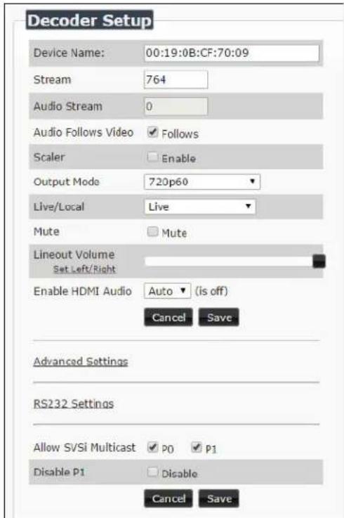
FIG. 3 Decoder Setup Section
TABLE 1 Settings Page: Decoder Setup Section
| Option Description Notes | ||
| Device Name | Enter a user-friendly name for the unit. | More descriptive names in this field help you organize and manage the SVSI system efficiently. Names based on the unit's location and function are very useful. Some good examples areLobby-Left-VGA(for left side of lobby, VGA input) orCR201-HDMI(for Conference Room 201, HDMI input). Keep in mind the matrices are organized alphanumerically. |
| Stream | View/edit the current transmit stream number. | To better understand this setting, think of Decoders dialing up channels on a cable box, rather than a traditional AV matrix. Each decoder can dial in a different active channel. |
| Audio Stream View/ | edit the current audio receive stream number. | |
| Audio Follows Video | Enable to force theAudio Stream tothe same as the video stream. | |
| Scaler Enable to | scale outgoing content to a fixed resolution or to use theCrop/Pan/Zoomfunctions. | |
| Output Mode Select | the output resolution of the video to be transmitted to the video output device (e.g., LCD) (theScalercheck box must be enabled for this to be applicable). | |
| Live/Local | Select live video or locally stored images for transmission to the video output device (e.g., LCD).When video is not available, it automatically goes into local mode. | When video is not available, the most recently played local playlist is displayed. |
| Mute | Enable to mute output audio. | |
| Lineout Volume This | slider controls the output gain on the analog audio output. By default, it controls both the left and right lineout channels. Click the Set Left/Right link to control channels individually. | |
| Enable HDMI Audio Set | HDMI audio to be disabled, enabled, or selected automatically based on the source. | ON forces audio on at all times. AUTO reads the EDID of the connected device to determine whether or not to send audio. |
| Advanced Settings | Refer to Advanced Settings on page 50 for details on the options available from this link. | |
| RS232 Settings | Refer to RS232 Settings on page 52 for details on the options available from this link. | |
| Allow SVSI Multicast | Disable this option to prevent the port from outputting multicast video traffic. | Particularly useful if you are connecting a non-SVSI device to a port for network-based control. |
| Disable P1 | Completely disables the P1 port for all traffic. | Once disabled, anything connected to the P1 port will no longer be available on the network. |
| Cancel Click to return all controls to the last saved configuration. | ||
| Save Click to accept changes made to these controls. | ||
Advanced Settings
The section of the Settings page shown in Figure 4 is displayed when you click the Advanced Settings link. Options are described in Table 2.
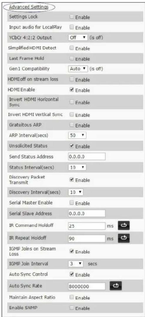
FIG. 4 Advanced Settings
TABLE 2 Settings Page: Advanced Settings
| Option Description Notes | ||
| Settings Lock Enable to lock the Decoder IP settings and stream number, preventing automated processes (from N-Able or N-Command) from occurring. | This does not prevent a control system from making changes or a user from manually making changes. | |
| Input audio for LocalPlay | Select to enable the input audio when the Live/Local menu is set to one of the local Images. | |
| YCbCr 4:2:2 Output Set | YCbCr output to be disabled, enabled, or selected automatically based on the connected display. | |
| Simplified HDMI Detect | Select to enable the detection of a display device using a simple line level check. | |
| Last Frame Hold Select to cause the Decoder to continue playing the last valid video frame if the network connection is lost. | When enabled, Local Play will not appear. | |
| Option | Description | Notes |
| Gen 1 Compatibility Set | compatibility with the color space of legacy equipment to be disabled, enabled, or selected automatically based on the identifying information in the video stream. | |
| HDMI off on stream loss | Select to disable the video output drive when the video stream is not available. | |
| HDMI Enable Select | to enable output video. | |
| Invert HDMI Horizontal Sync | Select to invert the polarity of the horizontal sync signal driven to the display device. | |
| Invert HDMI Vertical Sync | Select to invert the polarity of the vertical sync signal driven to the display device. | |
| Gratuitous ARP Enable | the Decoder to send a periodic Address Resolution Protocol (ARP) packet to the network. | |
| ARP Interval (secs) Determine how often (in seconds) the unit transmits gratuitous ARP packets. | ||
| Unsolicited Status Enable the Decoder to send a periodic status packet to the Send Status Address described below. | ||
| Send Status Address | When Unsolicited Status is enabled, the Decoder sends a periodic status packet to the IP address specified here. | |
| Status Interval (secs) Determine how often (in seconds) the unit transmits status packets. | ||
| Discovery Packet Transmit | Enable the SVSI multicast discovery service (which is used to identify units). | This is useful for larger network integrations when broadcast packets will not cover the entire network. Enabled by default. |
| Discovery Interval (secs) | Determine how often (in seconds) the unit transmits discovery packets. | |
| Serial Master Enable | Enable this device to be the master to the designated client. | |
| Serial Client Address | Enter the IP address of the serial client device. | |
| IR Command Holdoff Set | the delay between IR command portions. The default setting is 25 ms. | IR commands are sent in two parts. This setting is the time (in milliseconds) between transmission of part one and part two. The second part of the command is inverted for confirmation purposes. |
| IR Repeat Holdoff Set | the repeat delay between IR commands. The default setting is 90 ms. | This is the amount of time before a new command is sent. For example, when pressing and holding the volume button on a remote control, this is how long until the command is repeated. |
| IGMP Joins on Stream Loss | Enable to send Internet Group Management Protocol (IGMP) join messages when no incoming stream is detected. | |
| IGMP Join Interval Delay in seconds between sending IGMP join messages (if IGMP Joins on Stream Loss is enabled). | ||
| Auto Sync Control Enable synchronization of vertical sync with the network. | Enable this option when using multiple Decoders (e.g, when building a video wall) that must be synchronized together. | |
| Auto Sync Rate Set the rate at which the vertical sync adjusts. | ||
| Maintain Aspect Ratio When scalers are enabled, enabling this check box maintains the source's aspect ratio. | ||
| Enable SNMP | Enable to allow the device to send Simple Network Management Protocol (SNMP) packets. | |
RS232 Settings
The section of the Settings page shown in Figure 5 is displayed when you click the RS232 Settings link. Options are described in Table 3.

FIG. 5 RS232 Settings
TABLE 3 Settings Page: RS232 Settings
| Option Description | |
| RS232 Baud Rate | Select the appropriate baud rate for the RS232 serial interface. Default is 9600. |
| RS232 Data Bits | Select the appropriate data bit count for the RS232 serial interface. Default is 8. |
| RS232 Parity | Select the appropriate parity for the RS232 serial Interface. Default is no parity (none). |
| RS232 Stop Bits | Select the appropriate number of stop bits for the RS232 serial interface. Default is 1. |
Network Setup Section
The Network Setup section of the Settings page is shown in Figure 6. Options are described in Table 4.

FIG. 6 Network Setup Section
TABLE 4 Settings Page: Network Setup Settings
| Option Description Notes | ||
| IP Mode | Configure the IP address mode. When set to AUTO IP, an IP Address in the range of 169.254.xxx.xxx with Netmask of 255.255.0.0 and Gateway address of 169.254.1.1 will be automatically assigned to the N2000 Decoder by the control software. When set to DHCP, an IP Address in the range of the DHCP server on the network will be automatically assigned to the N2000 Decoder. When set to STATIC, an IP address, Netmask, and Gateway address must be manually entered. | Using DHCP is generally not recommended. If the device is set to DHCP and fails to receive an address from the DHCP server in time, it will revert back to the AUTO IP Address (169.254.xxx.xxx) until the unit is rebooted. |
| IP address View the current IP address of the N2000 Decoder.When in STATIC mode, enter a new IP address into this field. | ||
| Netmask | View the current Netmask of the N2000 Decoder. When in STATIC mode, enter a new Netmask into this field. | |
| Gateway address | View the current Gateway address of the N2000 Decoder. When in STATIC mode, enter a new Gateway address into this field. | |
| Trial Save | Click to initially save IP address changes. Once you log in to the unit using the new address, you will be able to confirm and accept the changes permanently. | |
Status Section
The Status section of the Settings page is shown in Figure 7. Options are described in Table 5.
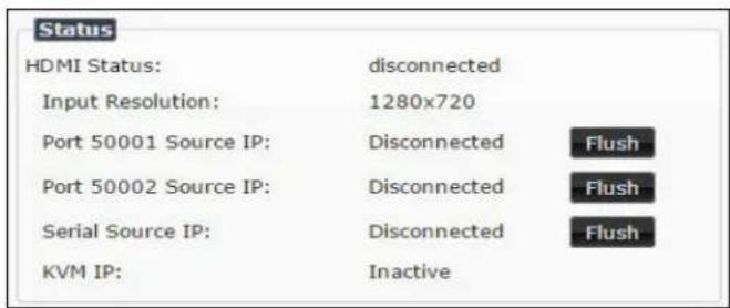
FIG. 7 Status Section
TABLE 5 Settings Page: Status Section
| Option Description Notes | ||
| HDMI Status Indicates if video is connected to the Decoder. | ||
| Input Resolution Indicates the video resolution of the incoming video source. | ||
| Port 50001 Source IP Shows the IP address of the currently connected device or displays Disconnected if no connection exists. | Port 50001 can only accept a single external connection at a time. If a device is currently showing the port occupied (by a control system or other device), then other connections will be rejected. However, connection attempts from the same IP will override the current connection. | |
| Port 50002 Source IP Shows the IP address of the currently connected device or displays Disconnected if no connection exists. | Port 50002 can only accept a single external connection at a time. If a device is currently showing the port occupied (by a control system or other device), then other connections will be rejected. However, connection attempts from the same IP will override the current connection. | |
| Serial Source IP Shows the IP address of the currently connected device or displays Disconnected if no connection exists. | Only a single external connection can be accepted on the port. If a device is currently showing the port occupied (by a control system or other device), then other connections will be rejected. However, connection attempts from the same IP will override the current connection. | |
| Flush buttons These buttons reset the port. | ||
| KVM IP | Shows the IP address of the KVM Encoder currently connected to this Decoder. | |
Change Password
To change the N2000 Decoder interface password, enter the current password in the field labeled Old Password, and enter a new password in the New Password and Confirm Password fields. Click Change PW to accept the new password.

FIG. 8 Change Password
NOTE: This password needs to match N-Able's stored password to allow auto-login using N-Able.
Software Section
The Software section of the Settings page is shown in Figure 9. Options are described in Table 6.
Software
Serial: N2235A00000009
MAC address 00:19:0B:CF:70:09
Firmware Version: v1.0.0 (8/7/2015)
Web Version: 8/4/2015
Factory Restore
Reboot
FIG. 9 Software Section
TABLE 6 Settings Page: Software Section
| Option Description | |
| Serial Displays the serial number of the N2000 Decoder. | |
| MAC Address Displays the MAC address of the network interface of the N2000 Decoder. | |
| Firmware Version | Displays the date code for the currently running version of the N2000 Decoder internal firmware. |
| Web Version | Displays the date code for the currently running version of the web interface. |
| Factory Restore | Click to restore the device to the original factory settings. This resets everything except the IP address (including name, stream number, serial settings, etc.). |
| Reboot Click to reboot the device (does not affect current configuration). | |
Audio Downmixer Settings
The section of the Settings page shown in Figure 10 is displayed when you click the Audio Downmixer Settings link. Options are described in Table8.
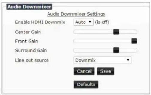
FIG. 10 Audio Downmixer Settings
TABLE 8 Settings Page: Audio Downmixer Settings
| Option Description | |
| Enable HDMI Downmix | Set HDMI audio downmixing to be disabled, enabled, or selected automatically when receiving a 7.1 audio source. |
| Center Gain slider | Set percentage of audio on center channel mixed into left and right output when downmixing. |
| Front Gain slider | Set percentage of audio on front left and right channels mixed into left and right output (respectively). |
| Surround Gain slider | Set percentage of audio on surround when downmixing left and right channels mixed into left and right output (respectively). |
| Line out source | Select a line out source or selectDownmixwhen using the downmixer. |
| Cancel Click to return all controls to the last saved configuration. | |
| Save | Click to accept changes made to these controls. |
| Defaults | Click to return all controls to their default settings. |
Crop/Pan/Zoom Page
Click the Crop/Pan/Zoom link at the top of any of the main web pages to access the page shown in Figure 11. This page allows you to customize the viewable portion of the input. See Table9 for option descriptions.

FIG. 11 Crop/Pan/Zoom Page
NOTE: The Scaler check box must be enabled for changes on this page to take effect. See the Settings Page: Decoder Setup Section table on page 48 for more information.
TABLE 9 Crop/Pan/Zoom Page Options
| Option Description | |
| X1, Y1 Set pixel coordinates of viewing area (top left). | |
| X2, Y2 Set pixel coordinates of viewing area (bottom right). | |
| 16:9 Aspect Ratio Enable to force to a 16:9 ratio. | |
| No Crop | Click to disable existing crop settings and return unit to default output settings. |
| Execute Crop Reference Click to execute changes. | |
| Save Crop Reference | Click to save the current settings and store them as a preset for later use. Presets can be used by third-party controllers. |
| Stored Crop Presets | Use this section of the page to select/delete/export/import cropping presets. |
LocalPlay Page
Click the LocalPlay link at the top of any of the main web pages to access the screen shown in Figure 12. This page allows you to upload new images to the Decoders and configure the image playlists. The playlist will be shown on the display when no video is being transmitted or received. You can show a single image or set up multiple images to be displayed at a customized animation rate. Audio can be uploaded and set to play whenever LocalPlay is active. See Table 10 for option descriptions.
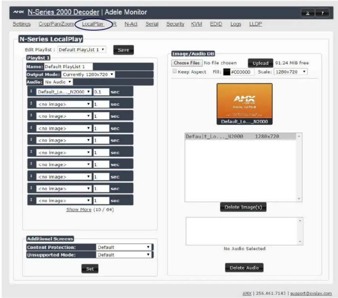
FIG. 12 LocalPlay Page
TABLE 10 LocalPlay Page Options
| Option Description | |
| Edit Playlist | Select a playlist from the drop-down menu to view/edit the images currently used in the chosen image playlists. If more than one image appears in the list, a transition time can be set for each image. |
| Save Click to save the current configuration. | |
| Name View/edit | playlist names. |
| Output Mode Select | the resolution you want the Image(s) to play In. |
| Audio Select an | audio file to play while the LocalPlay image is on the screen. |
| Image List | Allows you to customize what images are displayed, the transition time for each image, etc. |
| Additional Screens | Allows you to choose what is displayed as the LocalPlay page if there is a communication or content protection issue. |
| Image/Audio DB | This section allows you to upload image and audio files to the N2000 Decoder database. You can also use the Fill field to customize the background color (used behind LocalPlay Images that do not take up the entire screen). |
| Delete Image(s) Delete the selected image file from the playlist. | |
| Delete Audio Delete the selected audio file from the playlist. | |
IR Page
Click the IR link at the top of any of the main web pages to access the page shown in Figure 13. This page allows you to upload and execute IR Pronto codes so that other vendor's devices can be controlled through the Decoder's IR connector. Commands can be saved for future use and executed later. The IR Code menu lists all saved IR commands. See Table 11 for option descriptions.

FIG. 13 IR Page
TABLE 11 IR Page Options
| Option Description | |
| IR Code | Create/select IR codes. Different vendors have different IR Pronto codes and can usually be found through a web search. Copy/paste new IR commands directly into the input space. |
| Save Save the current code. | |
| Delete Delete the current code. | |
| Execute | Activate the selected code through the Decoder's IR connector. |
N-Act Page
Click the N-Act link at the top of any of the main web pages to access the page shown in Figure 14. This page allows you to create command lists which are performed automatically by the unit based on power or video connection (without the use of an outside controller). For example, you can tell a projector and lights to come on when the Decoder powers up. You can add multiple commands for each event. See Table12_ for option descriptions.
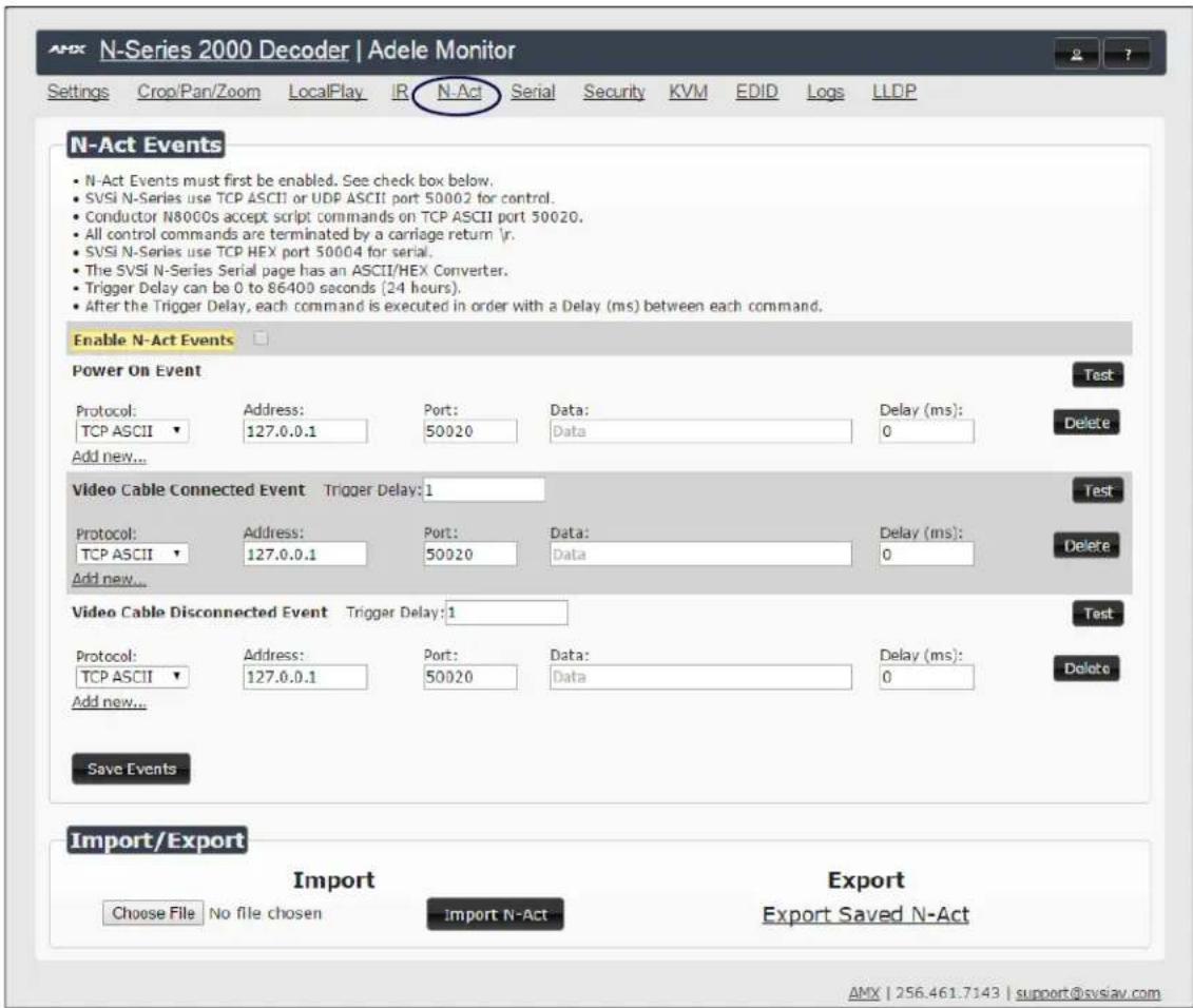
FIG. 14 N-Act Page
TABLE 12 N-Act Page Options
| Option Description | |
| Enable N-Act Events Enable to activate the configured events. | |
| Power on Event | Create/delete/test events to be performed when the Decoder powers on. Visit our website for more details on Application Programming Interface (API) commands. |
| Video Cable Connected Event | Create/delete/test events to be performed when the Decoder is connected to an output display. The Trigger Delay field specifies how long the device has to be connected for the command to be executed. |
| Video Cable Disconnected Event | Create/delete/test events to be performed when the Decoder is disconnected from the output display. The Trigger Delay field specifies how long the device has to be disconnected for the command to be executed. This keeps accidental (momentary) disconnects from triggering the command sequence. |
| Save Events Click to save changes made to this page. | |
| Import/Export | Use this section of the page to Import/export N-Act event configurations, from one unit to others. |
Serial Page
Click the Serial link at the top of any of the main web pages to access the page shown in Figure 15. This page allows you to upload and execute commands used for direct control of serial devices. Commands may be saved for future use and executed later. The Serial Code menu lists all saved commands. See Table 13 for option descriptions.
NOTE: If the Port 5004/Serial Port is currently in use by another device, sending commands from the Serial page will always return a No Data message and fail to send the commands.
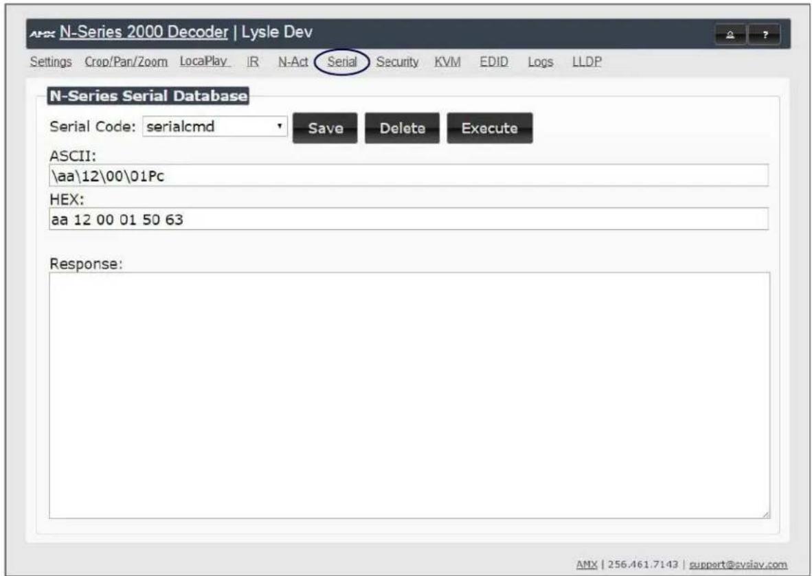
FIG. 15 Serial Page
TABLE 13 Serial Page Options
| Option Description | |
| Serial Code | Create/select serial commands. Different vendors have different codes that can usually be found through a web search. Copy/paste new commands (in either ASCII or HEX) directly into the appropriate input space. |
| Save Save the current code. | |
| Delete Delete the current code. | |
| Execute Send the selected code out the Decoder's serial connection. | |
| ASCII and HEX | Paste serial commands directly Into either the ASCII or HEX field. |
| Response | View responses provided by the device receiving the serial command(s). |
Security Page
Click the Security link at the top of any of the main web pages to access the page shown in Figure 16. This page allows you to force HTTPS connections and set up a default password for stream encryption. To successfully communicate, the Decoder must know and match the Encoder password.

FIG. 16 Security Page
KVM Page
Click the KVM link at the top of any of the main web pages to access the N-Series KVM page. You must check the USB Enable box at the top to see the page shown in Figure 17. See Table 14 for option descriptions. This page applies to KVM units only (N2135 Encoder and N2235 Decoder).

FIG. 17 KVM Page
TABLE 14 KVM Page Options
| Option Description | |
| USB Enable | Enable to allow the ability to share mouse and keyboard over the network. Enabled by default. When disabled, the unit works like a non-KVM unit and ignores any keyboard or mouse activity. |
| Multiaccess | Enable to allow multiple Decoders to access this Encoder at the same time. (maximum is 100 connections). See the section Advanced KVM Setup (With Added Security Features) on page 27 for more information. |
| Permission Level | Set the permission level for the Decoder. Decoders can only establish USB connection to Encoders with the same or higher permission level. See the section Advanced KVM Setup (With Added Security Features) on page 27 for more information. |
| Import KVM CSV | Click the Choose File button and browse to the KVM CSV file on your computer that you would like to use to configure the unit. Then click Upload. For more information, see the section Advanced KVM Setup (With Added Security Features) on page 27. |
| Export KVM CSV | Click the Download KVM CSV Export link to retrieve the current KVM CSV configuration file. |
| KVM Encoders | View/edit the list of Encoders associated with this Decoder. Here you can Add new/overwrite Encoders to the list by Name or IP Address as well as assign Hotkey Numbers and Passwords. You can also end the Decoder/Encoder association by clicking the Remove button. |
EDID Page
Click the EDID link at the top of any of the main web pages to access the page shown in Figure 18. Every display has stored information that it communicates to the output device. This page allows you to view the EDID information of the connected output display.

FIG. 18 EDID Page
TABLE 15 EDID Page Options
| Option Description | |
| EDID Display Shows | the EDID of the display that is connected to the Decoder. |
| Decode button | Click to translate the EDID currently displayed on the left to the operating parameters list on the right. |
| Encode button | After making any changes to the operating parameters list on the right, click this button to update the EDID Information on the left. |
Logs Page
Click the Logs link at the top of any of the main web pages to access the page shown in Figure 19. The Logs page displays a command log that lists all TCP and UDP messages the unit receives. It also displays the web browser's IP address and gives you options to Refresh and Reset Logs.
| Elapsed Time | IP | Port Method | Command | |
| 41 min, 57 sec | Web page | 50003 | TCP | set:1001\r |
| 4 hrs, 14 min, 23 sec | Web page | 50003 | TCP | set:1004\r |
| 4 hrs, 14 min, 29 sec | Web page | 50003 | TCP | set:1001\r |
| 4 hrs, 15 min, 31 sec | Web page | 50003 | TCP | set:1004\r AMX |
| 6 days, 22 hrs, 58 min, 52 sec | Web page | 50003 | TCP | set:6995\r |
| 6 days, 23 hrs, 50 min, 49 sec | Web page | 50003 | TCP | set:1003\r |
| 7 days, 45 sec | Web page | 50003 | TCP | set:1001\r |
| 7 days, 1 min, 1 sec | Web page | 50003 | TCP | set:1003\r |
| 7 days, 10 min, 33 sec | Web page | 50003 | TCP | set:1002\r |
| 7 days, 11 min, 51 sec | Web page | 50003 | TCP | set:1005\r |
| 7 days, 18 min, 22 sec | Web page | 50003 | TCP | set:1004\r |
| 7 days, 52 min | Web page | 50003 | TCP | scalerenable\r |
| 7 days, 52 min, 17 sec | Web page | 50003 | TCP | scalerdisable\r |
| 7 days, 2 hrs, 27 min, 17 sec | Web page | 50003 | TCP | setSettings:autoSyncControl:on\r |
| 7 days, 2 hrs, 29 min, 4 sec | Web page | 50003 | TCP | set:6995\r |
| 7 days, 2 hrs, 29 min, 8 sec | Web page | 50003 | TCP | setSettings:autoSyncControl:off\r |
| 7 days, 2 hrs, 29 min, 16 sec | Web page | 50003 | TCP | set:6993\r |
| 7 days, 2 hrs, 29 min, 30 sec | Web page | 50003 | TCP | set:6995\rresetSettings:autoSyncControl:on\r |
| 7 days, 2 hrs, 29 min, 42 sec | Web page | 50003 | TCP | set:6993\r |
| 7 days, 2 hrs, 30 min, 19 sec | Web page | 50003 | TCP | setSettings:autoSyncControl:off\r |
| 7 days, 2 hrs, 48 min, 48 sec | Web page | 50003 | TCP | set:6995\r |
| 7 days, 2 hrs, 49 min, 51 sec | Web page | 50003 | TCP | modeset:1080p60\r |
| 7 days, 2 hrs, 49 min, 58 sec | Web page | 50003 | TCP | cropref:0,0,0,0\r |
| 8 days, 1 hrs, 17 min, 45 sec | Web page | 50003 | TCP | set:6999\r |
| 8 days, 1 hrs, 20 min, 24 sec | 169.254.1.57 | 50001 | UDP | set:6994\r |
FIG. 19 Logs Page
LLDP Page
Click the LLDP link at the top of any of the main web pages to access the page shown in Figure 20. The LLDP page displays information from the Link Layer Discover Protocol (LLDP) packet which identifies the port number and switch the device is connected to.
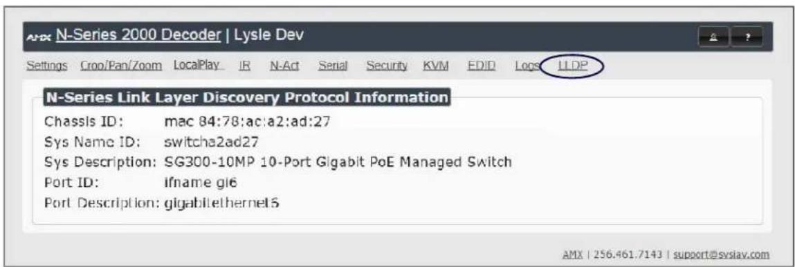
FIG. 20 LLDP Page
Troubleshooting
This chapter contains possible solutions to some common issues. Should you encounter any problems not covered by these guidelines, please contact SVSI technical support via email (svsisupport@harman.com) or call 256.461.7143 x9900. You can also visit our support webpage at support.svsiav.com.
| Issues Suggestions | |
| LocalPlay screen displays instead of the stream from the Encoder. | ·Verify Decoder is assigned to view a valid stream (of an active Encoder).·Verify Decoder is currently inLiveplay mode (its name will display in black text on theVideo Matrixpage). You can change toLivemode on theSettingspage (see theSettings Page: Decoder Setup Section table on page 48 for more details).·Verify network is properly configured and set up. If needed, connect Encoder's network port to Decoder to bypass the network. |
| HostPlay screen displays instead of the video from the source. | ·Verify Encoder is inLiveplay mode (its name will display in black text on theVideo Matrixpage). You can change toLivemode on theSettingspage (seeSettingsPage: Encoder Setup Section table on page 30 for more details).·Verify source is attached and is outputting a valid signal (HDMI LED on Encoder is on). |
| Unsupported Input Resolution screen displays. | ·Change source resolution to a valid resolution (try720p60).·Verify cabling is correct. |
| Copy Protected Content screen displays.·Contact SVSI technical support. | |
| Black screen/no screen displays. | ·Set Decoder toLocalPlay.If theLocalPlayscreen does not appear, check the display input settings and cabling. As mentioned previously in this table, you can change to theLocalmode on the Decoder'sSettingspage.·IfLocalPlayappears, set Decoder toLiveplay mode and verify network is configured properly. |
| No audio is detected.·If there is no audio on all__Decoders, verify audio settings are correct on Encoder.·If there is no audio on a single Decoder, verify audio settings are correct on Decoder. | |
| Device has been discovered in N-Able, but the configuration pages do not open when double-clicking device name on the Video Matrix page. | ·Make sure your computer is in the same IP address range as the unit. See :Setting Up Your Host Computeron page 16 for more information. |
| When changing the audio type, there are problems with audio in/out. | ·Check theAudio Source(Encoder)andHDMI Audio(Decoder)settings on theSettingspage. For example, if you are trying to change the audio type to make the input of the Encoder HDMI embedded audio in/analog audio out from the Decoder, these settings cannot be set toAuto. Set the Encoder toAudio Source>ON(embedded digital audio on an HDMI connection) and the Decoder toEnable HDMI Audio>OFF(analog output on the Phoenix connection). |
| Not receiving audio. | ·Check that the Decoder has proper audio stream setting (typically by enabling Audio follows Video). |
| Not receiving analog video through the Encoder. | ·If using a Y cable (N9420) and an HDMI source is already connected to the Encoder, disconnect the HDMI source. Encoders give preference to HDMI and will not allow analog signal to pass while it is connected. |
| Video output is stuttering. | ·This could be a network bandwidth issue where the full video stream is not reliably getting from Encoder to Decoder. Contact your network administrator for assistance. |
| Experiencing a red/blue color swap. | ·CheckGen1 Compatibility Mode. If the entire system is N-Series, set toOff. If the system is mixed (V-Series and N-Series), set toOnfor the N-Series Decoder. See Advanced Settings on page 50 for more information on this mode. |
| Serial port is not working as expected. | ·Verify theRS232 Settingson theSettingspage. Flush the serial port on theSettingspage if another device is connected.·Connecting the Tx and Rx pins on the RS232 connector creates a loopback that could also help when troubleshooting. |
Series Default Local/Host Play Troubleshooting Screens
This section shows and defines the status screens displayed by N2000 Series devices.

FIG. 21 Host Play Screen
| Displayed when Decoder.... ...and Encoder.... Notes | ||
| • is set to view an Encoder stream on the network | • is set to Host PI• does NOT have a valid input video signal | Seeing this screen means that the Decoder CAN communicate with the Encoder across the network. It is a good way to troubleshoot network communication between segments using only Encoders and Decoders (without the need for source video Into an Encoder). |
FIG. 22 Local Play Screen
| Displayed when Decoder.... Notes | |
| • is set to LocalPlay mode | If the Decoder is NOT set to Local Play mode, this screen could signify a network communication issue. |

by HARMAN
Unsupported Input Resolution
Please Contact Your AV Installer
www.amx.com/svsi
Distribution | Switching | Control | Windowing | Wall Processing | Recording
FIG. 23 Unsupported Input Resolution Screen
| Displayed when Decoder.... ...and Encoder.... Notes | ||
| • is set to view an Encoder stream on the network | • is being fed a video resolution that it does not support | This screen can be useful to show you that the Decoder is receiving the stream from the intended Encoder. However, the video signal being sent to the Encoder is not supported.Please refer to the AMX website???need link??? for the listing of supported resolutions. |

FIG. 24 Restricted Content Not Supported Screen
| Displayed when Decoder.... ...and Encoder.... Notes | ||
| • is receiving a stream from an Encoder• is connected to a monitor that does NOT support Restricted Content (i.e., the monitor is NOT HDCP compliant) | • is transmitting HDCP-protected content to the Decoder | Once the Decoder detects that the monitor Is not HDCP compliant, this screen is displayed. If you suspect that this message was displayed in error, please call Technical Support. |
NOTE: The Encoder must first be set up to pass HDCP-protected content.

by HARMAN
This video source is outputting restricted content
Please contact your AV installer
www.amx.com/svsi
Distribution | Switching | Control | Windowing | Wall Processing | Recording
FIG. 25 Video Source Outputting Restricted Content Screen
| Displayed when Decoder.... ...and Encoder.... Notes | ||
| • is receiving a stream from an Encoder | • is receiving HDCP-protected content from the video source, but is not set up to pass it. | Please call SVSI Technical Support to enable this feature. |

by HARMAN
Video is Encrypted
Please Contact Your AV Installer
www.amx.com/svsi
Distribution | Switching | Control | Windowing | Wall Processing | Recording
FIG. 26 Video Encrypted Screen
Displayed when Decoder.... Notes
| • is receiving a stream from an Encoder it can not decrypt | Make sure the Decoder has the correct password for decrypting the stream. To reset the password, go to the Security page on both the Encoder and Decoder and click the Reset button. Refer to the Security Page section on page 61 if you are not sure where to find this setting. |


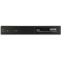

- IMPORTANT SAFETY INSTRUCTIONS
- COPYRIGHT NOTICE
- LIABILITY NOTICE
- AMX WARRANTY AND RETURN POLICY
- ESD WARNING
- FCC AND CANADA EMC COMPLIANCE INFORMATION:
- EU COMPLIANCE INFORMATION:
- WEEE NOTICE:
- Table of Contents
- Introducing Your New N2000 Series Devices 6
- Installing and Configuring Your AV Equipment 13
- Encoder Configuration Options ......28
- Introducing Your New N2000 Series Devices
- Product Overview
- HD AV over IP Series
- Low-Latency AV over IP Series
- Application Examples
- Installing and Configuring Your AV Equipment
- Installation Overview
- Mounting Options
- Surface and Wall Mounting
- Rack Mounting
- N2000 Series Stand-Alone Units
- N2000 Series Cards
- Step-by-Step Installation Instructions
- There are PoE switches operational on the network.
- Deployment considerations have been made for the addition of high-speed video.
- You loaded N-Able onto the computer you are using to configure the equipment.
- Step 1: Setting Up Your Host Computer
- Step 2: Connecting Decoders to the Network
- Step 3: Connecting Encoders to the Network and Configuring Stream Settings
- Step 4: Configuring Decoder and Encoder IP addresses (if needed)
- How IP Address Changes Affect Unit Control
- Changing IP Addresses
- Option 1: Assigning IP Addresses Individually (using the Settings page)
- Option 2: Assigning IP Addresses to Multiple Units (using CSV files)
- Step 5: Connecting Encoders to an Input Source
- Switching and Scaling Options
- Seamless Switching
- Control Options
- Primary Control Options
- N-Command Controllers
- Third-Party Controllers
- N-Act | On-Board, Built-In Control
- N-Touch | IP Wall Controller
- KVM Configuration
- Basic Setup
- Video/USB Switching Options
- Advanced KVM Setup (With Added Security Features)
- Encoder Configuration Options
- Settings Page
- Encoder Setup Section
- Advanced Settings
- RS232 Settings
- Network Setup Section
- Status Section
- Change Password
- Software Section
- HDMI Pass Thru Settings
- Crop/Pan/Zoom Page
- HostPlay Page
- IR Page
- N-Act Page
- Serial Page
- Security Page
- KVM Page
- EDID Page
- Logs Page
- LLDP Page
- Decoder Configuration Options
- Decoder Setup Section
- Software
- Audio Downmixer Settings
- LocalPlay Page
- Troubleshooting
- Series Default Local/Host Play Troubleshooting Screens
Brand : AMX
Model : NMX-DEC-N2212
Category : Audiovisual Equipment