NMX-DEC-N2211 - Audiovisual Equipment AMX - Free user manual and instructions
Find the device manual for free NMX-DEC-N2211 AMX in PDF.


| Product Type | Video Decoder |
| Model | NMX-DEC-N2211 |
| Brand | AMX |
| Dimensions (W x D x H) | Approx. 21.6 x 20.3 x 4.4 cm (8.5 x 8.0 x 1.7 in) |
| Weight | Approx. 1.0 kg (2.2 lbs) |
| Power Supply | 12V DC, 1.5A (PoE capable) |
| Power Consumption | Max 12W |
| Video Input | HDMI, VGA, Composite (via optional adapter) |
| Video Output | HDMI, H.264/H.265 streaming |
| Audio Support | Embedded audio via HDMI, analog stereo input |
| Network Interface | 10/100/1000 Mbps Ethernet (RJ-45) |
| Streaming Protocols | RTSP, RTP, MPEG-TS, HLS |
| Control Protocol | AMX Netlinx, TCP/IP, serial RS-232 |
| Maximum Resolution | 1920x1080 @ 60fps |
| Operating Temperature | 0°C to 40°C (32°F to 104°F) |
| Storage Temperature | -20°C to 60°C (-4°F to 140°F) |
| Humidity | 10% to 90% non-condensing |
| Mounting | Desktop or rack-mount (bracket sold separately) |
| Included Accessories | Power supply, quick start guide |
| Maintenance | Keep clean with dry cloth; avoid liquids |
| Safety Certifications | CE, FCC Class A, RoHS |
| Repairability | No user-serviceable parts; contact AMX support |
Frequently Asked Questions - NMX-DEC-N2211 AMX
User questions about NMX-DEC-N2211 AMX
0 question about this device. Answer the ones you know or ask your own.
Ask a new question about this device
Download the instructions for your Audiovisual Equipment in PDF format for free! Find your manual NMX-DEC-N2211 - AMX and take your electronic device back in hand. On this page are published all the documents necessary for the use of your device. NMX-DEC-N2211 by AMX.
USER MANUAL NMX-DEC-N2211 AMX
SVSi N-Series Encoders/Decoders
N2121/N2211/N2221
N2141/2241
Table of Contents
Chapter I. Introduction
Product Overview 8
HD AV over IP Series 8
N2121 HD AV over IP Encoder 8
N2211 HD AV over IP Decoder (non-PoE) 8
N2221 HD AV over IP Decoder 8
Low-Latency AV over IP Series 9
N2141 Low-Latency AV over IP Encoder 9
N2241 Low-Latency AV over IP Decoder 9
Rear Panel Ports and LEDs 9
Application Examples 12
Chapter 2. Installation
Introduction 15
Installation Overview 15
Mounting Options 17
Surface and Wall Mounting 17
Rack Mounting Options 18
N2000 Series Stand-Alone Units 18
N2000 Series Cards 18
Step-by-Step Installation Instructions 20
Setting Up Your Host Computer 21
Connecting Decoders to the Network 23
Connecting Encoders to the Network and Configuring Stream Settings 25
Configuring Decoder and Encoder IP addresses (if needed) 29
How IP Address Changes Affect Unit Control 29
Changing IP Addresses 29
Option 1: Assigning IP Addresses Individually (using the Settings page) 29
Option 2: Assigning IP Addresses to Multiple Units (using CSV files) 30
Connecting Encoders to an Input Source 31
Switching and Scaling Options 32
Seamless Switching 32
Control Options 33
Primary Control Options 33
N-Command Controllers 33
Third-Party Controllers 33
Other Control Options 33
N-Act | On-Board, Built-In Control 33
N-Touch | IP Wall Controller 33
Software Bundles Included With N-Command 34
Chapter 3. Encoder Options
Encoder Introduction 36
Encoder Configuration Options 36
Settings Page 37
Encoder Setup Section 38
Advanced Settings 42
RS232 Settings 46
Network Setup Section 47
Status Section 49
Change Password 51
Software Section 52
EDID Section 53
DVI Pass Thru Settings 55
Crop/Pan/Zoom Page 56
IR Page 60
N-Act Page 61
Serial Page 63
EDID Page 65
Logs Page 66
LLDP Page 67
Chapter 4. Decoder Options
Decoder Introduction 68
Decoder Configuration Options 68
Settings Page 69
Decoder Setup Section 70
Advanced Settings 73
RS232 Settings 77
Network Setup Section 78
Status Section 80
Change Password 82
Software Section 83
EDID Section 84
Audio Downmixer Settings 85
Crop/Pan/Zoom Page 86
LocalPlay Page 88
IR Page 90
N-Act Page 91
Serial Page 93
EDID Page 95
Logs Page 96
LLDP Page 97
Chapter 5. Troubleshooting
Introduction 98
Trademarks
SVSi is a trademark of Southern Vision Systems, Inc. in the United States and other countries. All other brand names, product names and trademarks are the property of their respective owners. Certain trademarks, registered trademarks, and trade names may be used to refer to either the entities claiming the marks and names or their products. SVSi disclaims any interest in the marks and names of others.
To the Reader
The contents of this manual are current as of the date of publication. SVSi reserves the right to change the contents without prior notice.
In no event will SVSi be liable for any special, incidental, or consequential damages or for commercial losses (even if SVSi has been advised thereof) that result from issue or use of this publication.
Information in this document (including URL and other Internet website references) could change without notice.

360B Quality Circle NW Suite 200, Huntsville, AL 35806
Phone: 256.461.7143
Fax: 256.461.7145
Email: info@svsiav.com
Support Email: support@svsiav.com
Website: www.svsiav.com
All Rights Reserved.

Printed in U.S.A.
Conventions

Notes provide additional useful information.

Cautions provide information that could prevent service interruption or damage to the equipment.
Safety Instructions
Please read the safety precautions carefully before using this product. Ensure that you use the product correctly according to the procedures described in these instructions.
The following safety precautions are intended to instruct you in the safe and correct operation of the product and its accessories to prevent injuries or damage to yourself, other persons, and property. Please read and ensure that you understand them before you proceed to the other sections of these instructions.
- Do not operate this device in a wet environment.
- Refer servicing to qualified service personnel only.
- Please read this user manual and other provided documentation carefully before operating. Follow all operating and other instructions carefully.
- Do not use this product near heat sources such as radiators, air ducts, areas subject to direct, intense sunlight, or other products that produce heat.
Disclaimer
- While every effort has been made to ensure that the information contained in these instructions is accurate and complete, no liability can be accepted for any errors or omissions. SVSi reserves the right to change the specifications of the hardware and software described herein at any time without prior notice.
- SVSi makes no warranties for damages resulting from corrupted or lost data due to mistaken operation or malfunction of the hardware, software, or accessories.

Caution: Changes or modifications to this unit not expressly approved by the party responsible for compliance could void the user's authority to operate the equipment.
FCC Class A Notice
This equipment has been tested and found to comply with the limits for a Class A digital device, pursuant to Part 15 of the FCC Rules. Operation is subject to the following two conditions: (1) this device may not cause harmful interference, and (2) this device must accept any interference received, including interference that may cause undesired operation. The Class A limits are designed to provide reasonable protection against harmful interference when the equipment is operated in a commercial environment. This equipment generates, uses, and can radiate radio frequency energy and, if not installed and used in accordance with the instruction manual, may cause harmful interference to radio communications. Operation of this equipment in a residential area is likely to cause harmful interference, in which case the users will be required to correct the interference at their own expense.
To comply with FCC and Industry Canada RF exposure limits, this device must be installed to provide a separation distance of at least 20 cm from all persons and must not be co-located or operating in conjunction with any other antenna or transmitter.

Caution: These units contain no user-serviceable parts. They should only be serviced by qualified service personnel. Opening the unit could void the warranty.
Service and Warranty
For information on the service and warranty of SVSi products please visit our website at www.svsiav.com
PRODUCT OVERVIEW
SVSi's N2000 AV over IP Series provides a flexible, feature-rich, and simple-to-deploy digital media distribution and switching solution satisfying the most demanding applications. SVSi video over IP Encoders are used to encode and distribute sources of almost any format onto an existing IP network, making that stream available to any endpoint in the facility. Video over IP Decoders are used to decode SVSi's Networked audio/video (AV) streams back to DVI or HDMI format for display on any monitor. With the ability to direct any source stream to any display, large, low-cost switching and distribution systems are simple to deploy without proprietary cabling or dedicated switching hardware. Plug-n-play, auto-detect technology reduces installation and programming time.
Features include:
- 1080p/60Hz encoding and decoding (applies to N2141 and N2241).
- Backwardly compatible with SVSi's V-Series products.
- Input and Output Scaling – scaling performed in Encoders or Decoders for maximum flexibility with V-Series sources and displays.
- Power over Ethernet (PoE) – eliminates the need for a local power supply and speeds installation. Units can still be powered locally by 12VDC. This allows easy rack-mountable, high-density installations. (All units can be PoE powered except the N2211 Decoder.)
• Infrared (IR) emitter connection allows control of low-cost, IR-only display devices. - Fast install with Phoenix connectors for power, IR, RS232 serial, and analog audio interfaces.
- Pass-through DVI interface allows easy installation with local display, such as desktop PC applications.
HD AV over IP Series
The SVSi HD AV over IP Series includes the N2121 Encoder, the N2211 Decoder, and the N2221 Decoder. This series uses JPEG2000 compression to provide user-definable bandwidth consumption controls.
N2121 HD AV over IP Encoder
This JPEG2000 Encoder includes IR, serial, balanced audio, two network ports (one PoE), and a local video pass-through port. The unit accepts (auto-senses) analog or digital video input.
N2211 HD AV over IP Decoder (non-PoE)
This JPEG2000 Decoder includes serial and a single network port (non-PoE). The unit provides digital video output only and requires the N9312 external power supply (included in shipment).
N2221 HD AV over IP Decoder
This JPEG2000 Decoder has expanded LocalPlay and includes IR, serial, balanced audio, and two network ports (one PoE). The unit provides digital video output only.
Low-Latency AV over IP Series
SVSi's low-latency AV over IP Series includes the N2141 Encoder and the N2241 Decoder. This series provides low latency for 1080p/60Hz encoding and decoding.
N2141 Low-Latency AV over IP Encoder
This low-latency Encoder includes IR, serial, balanced audio, two network ports (one PoE), and a local video pass-through port. The unit accepts (auto-senses) analog or digital video input.
N2241 Low-Latency AV over IP Decoder
This low-latency Decoder has expanded LocalPlay and includes IR, serial, balanced audio, and two network ports (one PoE). The unit provides digital video output only.
REAR PANEL PORTS AND LEDS
See Figure 1-1, Figure 1-2, and Figure 1-3 to identify the ports on the back of your Encoders and Decoders.

1) 12VDC Input (not needed with PoE)
2) Status Indicators
3) RJ45 Auto-Sensing Gigabit Ethernet Switch Port — PoE
4) RJ45 Auto-Sensing Gigabit Ethernet Switch Port
5) IR Emitter Connection
6) RS232 Connection
7) Analog Audio Input Connection
8) Pass-Through DVI-D Connection
9) DVI-I Digital Input
Figure 1-1. N2121/N2141 Encoder Rear Panel

1) 12VDC Input (not needed with PoE)
2) Status Indicators
3) RJ45 Auto-Sensing Gigabit Ethernet Switch Port — PoE
4) RJ45 Auto-Sensing Gigabit Ethernet Switch Port
5) IR Emitter Connection
6) RS232 Connection
7) Analog Audio Output Connection
8) DVI-D Digital Output
Figure I-2. N2221/N2241 Decoder Rear Panel

1) 12VDC Input (external power required)
2) Status Indicators
3) RJ45 Auto-Sensing Gigabit Ethernet Switch Port
4) RS232 Connection
5) DVI-D Digital Output
Figure I-3. N2211 Decoder Rear Panel
Table I-I. Rear Panel Descriptions
| +12V 2A | 12 Volt DC power input. |
| PWR LED | On solid (green) when operating power is supplied (via PoE or local power supply). This activity is also shown by the PWR LED on the front panel. |
| DVI LED | On (green) when a DVI output connection exists. |
| STAT LED | On flashing (green) when there is software activity. This activity is also shown by the STAT LED on the front panel. |
| STRM LED | On (green) when the unit is streaming video. |
| P0 POE | 8-wire RJ45 female.10/100/1000 Mbps 10/100/1000Base-T auto-sensing gigabit Ethernet switch port.Provides both the network connection and the power to the Encoders and Decoders.*Not available on the N2211 Decoder. |
| P1 | 8-wire RJ45 female.10/100/1000 Mbps 10/100/1000Base-T auto-sensing gigabit Ethernet switch port. |
| IR | 2-pin terminal Phoenix connector. Provides IR output only (33 to 60 kHz). An emitter may be necessary (not included).*Not available on the N2211 Decoder. |
| RS232 | 3-pin terminal Phoenix connector which provides a serial control interface. Full duplex communication. Available terminal speed settings: 1200 to 115200 baud rate. |
| AUDIO | 5-pin terminal Phoenix connector which provides user-selectable balanced/unbalanced input. Dedicated audio output.*Not available on the N2211 Decoder. |
| DVI-D OUTPUT | DVI-D female; HDMI/DVI digital video/audio output. Allows for video and embedded digital audio output. |
| DVI-I INPUT | DVI-I female; HDMI/DVI digital video/audio input. Allows for the use of analog or digital video sources (as well as embedded audio).*Applies to Encoders only. |
APPLICATION EXAMPLES

flowchart
graph TD
    A["N2121 ENCODER"] -->|P0 POE| B["LOCAL MONITOR"]
    A -->|DVI-D| C["LAPTOP"]
    A -->|DVI-I| D["NETWORK"]
    A -->|DVI-D| E["N2221 DECODER"]
    E -->|P0 POE| F["DISPLAY"]
    E -->|DIGITAL| G["Digital"]
    style A fill:#f9f,stroke:#333
    style E fill:#bbf,stroke:#333
Figure I-4. Loop Through DVI Port on Encoder

flowchart
graph TD
    A["N2121 ENCODER"] -->|P0 POE| B["SET-TOP-BOX"]
    A -->|DVI-I| C["LAPTOP"]
    D["N2221 DECODER"] -->|P0 POE| E["DISPLAY"]
    D -->|DVI-D| F["DISPLAY"]
    B -->|DIGITAL OR ANALOG| A
    C --> G["IR RS232"]
    E --> H["IR OUTPUT"]
    F --> I["OR SERIAL"]
    G --> J["NETWORK"]
    H --> J
    I --> J
Figure I-5. IR and Serial Transmitter Port

flowchart
graph TD
    A["BLU RAY 1080p"] --> B["HDMI"]
    C["1024x768 LAPTOP"] --> D["VGA"]
    B --> E["N2121 ENCODER"]
    D --> F["N2121 ENCODER"]
    E --> G["DVI-I"]
    F --> H["DVI-H"]
    G --> I["NETWORK"]
    H --> I
    I --> J["720p or 1080p"]
    K["DISPLAY"] --> L["N2221 DECODER"]
    L --> M["DVI-D"]
    M --> I
Figure 1-6. Built-In Scaling Through Encoders and Decoders

flowchart
graph TD
    A["PTZ CAMERA"] -->|DIGITAL OR ANALOG| B["N2121 ENCODER"]
    B -->|P0 POE| C["LAPTOP"]
    B -->|P0 DVI-I| D["N2121 ENCODER"]
    D --> E["NETWORK"]
    E --> F["P1"]
    F --> G["DVI-D"]
    G --> H["PROJECTOR"]
    F --> I["DAISY-CHAINED*"]
    I --> J["DISPLAY"]
    D --> K["DAISY-CHAINED*"]
    K --> L["DISPLAY"]
    style E fill:#333,stroke:#fff,color:#fff
    note bottom
        *Daisy-Chaining is limited by bandwidth (total aggregate streams must be <1Gb/s)
    end
Figure I-7. Basic Networked AV

flowchart
graph TD
    A["BLU RAY"] --> B["LAPTOP"]
    B --> C["PTZ CAMERAS"]
    C --> D["SVSI NVR"]
    D --> E["Multi ADC ENCODERS IN 2U RACK MOUNT FOR HIGH DENSITY APPLICATIONS"]
    E --> F["LAYER 3 SWITCH"]
    F --> G["PROYECTOR"]
    F --> H["DISPLAY"]
    I["N2221 DECODER P1"] --> J["DAISY-CHAINED*"]
    K["N2221 DECODER P2"] --> J
    L["N2221 DECODER P3"] --> J
    M["N2221 DECODER P4"] --> J
    N["PROYECTOR"] --> J
    O["DISPLAY"] --> J
    J --> P["1"]
    J --> Q["2"]
    J --> R["3"]

flowchart
graph TD
    A["PTZ CAMERA"] --> B["N2121 ENCODER"]
    B --> C["N3000 ENCODER"]
    C --> D["LAPTOP"]
    D --> E["LAN"]
    E --> F["WAREHOUSE"]
    F --> G["SPEAKERS"]
    G --> H["DSP/POWER AMP"]
    H --> I["N4321 AUDIO TRANSCEVER"]
    I --> J["PROYECTOR"]
    J --> K["HOME OFFICE"]
    K --> L["N3000 DECODER"]
    L --> M["DISPLAY"]
    M --> N["PROJECTOR"]
    N --> O["N2221 DECODER"]
    O --> P["PROJECTOR"]
    P --> Q["N3000 ENCODER"]
    Q --> R["LAN"]
    R --> S["WAN"]
    S --> T["PROJECTOR"]
    T --> U["N2221 DECODER"]
    U --> V["PROJECTOR"]
    V --> W["N3000 ENCODER"]
    W --> X["LAN"]
    X --> Y["WAN"]
    Y --> Z["N3000 ENCODER"]
    Z --> AA["LAN"]
    AA --> AB["WAN"]
    AB --> AC["N3000 ENCODER"]
    AC --> AD["LAN"]
    AD --> AE["WAN"]
    AE --> AF["N3000 ENCODER"]
    AF --> AG["LAN"]
* Daisy-Chaining is limited by bandwidth (total aggregate streams must be <1Gb/s)
Figure I-8. Multi-Switch Enterprise Network
INTRODUCTION
This chapter provides an installation overview as well as a detailed step-by-step process for installation.
INSTALLATION OVERVIEW
The N2000 Encoders and Decoders have multiple configuration and installation options. For basic installation guidelines, see Table 2-1. For more detailed instructions, refer to Step-by-Step Installation Instructions on page 20.
Table 2-1. Basic Installation Guidelines
| Connections Options | |
| Power | Power over Ethernet (PoE): Connect the unit's P0 port to an active, PoE-enabled network switch (not supported on the N2211 Decoder). |
| External power supply: If not using PoE for power, connect a 12V regulated power supply (SVSi part number N9312) to the unit's two-pin terminal block plug connector labeled +12V 2A. | |
| Network | PoE units: If using PoE to power the unit, you should already have a network connection. |
| Externally powered units: If not using PoE, connect either the P0 or P1 port to the network using an Ethernet cable. | |
| Daisy-chain configuration: Once network connection is established to one unit, you can daisy chain additional units by connecting Ethernet cables between devices using their P0 and/or P1 ports. Keep in mind that the number of units supported in this configuration is limited by bandwidth (total aggregate streams must be less than 1 Gb/s).Note: PoE power is only supplied to the unit connected directly to the network. All other units in the daisy-chain must have an external power supply. | |
| Video | N2000 EncodersFor video encoding of a digital source, connect the source to the Encoder's DVI-D port using a video cable with a DVI-D connector (or adapter).For video encoding of a digital or analog source, connect the source to the Encoder's DVI-I port using a video cable with a DVI-I connector (or adapter). |
| N2000 DecodersFor video decoding, connect a digital display to the Decoder's DVI-D port using a video cable with a DVI-D connector (or adapter). | |
| Audio | N2000 EncodersFor audio encoding, connect a line level analog audio source to the Audio input terminal block plug connector, orUse the embedded audio from the video source. |
| N2000 DecodersFor audio decoding, connect a line level analog audio device to the Audio output terminal block plug connector, orSend audio embedded in the video connection to a monitor's speakers. |

Note: When the unit is not in use, remove the power cable and disconnect any other cables (e.g., Ethernet, audio, video) connected to the Encoders and Decoders.
Note: DVI-D output is the digitally converted analog signal from the DVI-I input. An appropriate adapter or interface cable is required for DVI to accommodate HDMI. With the correct adapter, the DVI-I Input port accepts component signals.
MOUNTING OPTIONS
The N2000 units are available in stand-alone and card versions. The stand-alone version can be free standing, surface mounted, wall mounted, or rack mounted. All cards must be rack mounted using the N9206 Card Cage (sold separately).
Surface and Wall Mounting
To mount your N2000 stand-alone unit to a flat surface or wall, follow these steps:
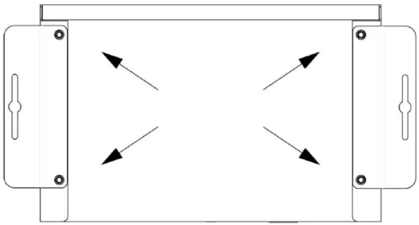
- Remove the four screws from the bottom of the unit and use them to attach the mounting wings (not included in shipment - SVSi part number N9101). See Figure 2-1.
- Place the unit against the solid surface to which you want it mounted.
- Using standard hardware, attach the unit through each of the slots of the newly-attached mounting wings.
- Connect the appropriate cables necessary for your application. Refer to the sections Connecting Decoders to the Network on page 23 and Connecting Encoders to the Network and Configuring Stream Settings on page 25 for more information on these connections.
natural_image
Pure diagram of a rectangular device with four directional arrows indicating flow or movement, no text or symbols present.Figure 2-1. Installing Mounting Wings
Rack Mounting Options
N2000 Series Stand-Alone Units
A Rack Shelf (SVSi part number N9102) accommodates up to two stand-alone N-Series Encoders or Decoders, side by side (mix and match).

Figure 2-2. Rack Mounting Stand-Alone Units
N2000 Series Cards
A Card Cage (SVSi part number N9206) accommodates up to six N-Series Encoder/Decoder cards (mix and match). The 12V power supply of the N9206 is the primary power source for the installed cards. If the 12V power supply fails or is unplugged, the cards will power down, detect PoE (if provided by switch) and restart normally using PoE. This usually results in a power loss of about one to two seconds. The unit then reboots (which takes another one to two minutes).
To rack mount N2000 Series cards into the N9206 Card Cage, follow these steps:
- Gently slide the card into cage slot. Make sure the card is properly aligned with guides. The card's front LED indicators should align with holes in the cage's faceplate. See Figure 2-3.

natural_image
Technical line drawing of a server rack with internal components and an open circuit board (no text or symbols)Figure 2-3. Rack Mounting Cards
- Align the thumb screw on back plate before seating card into cage.
- Firmly seat the card and tighten the thumb screw by hand to secure card placement.
- Use one of the six Phoenix connector cables (included in shipment with the Card Cage) to connect the card's 12VDC input Phoenix connector to one of the cage's six 12VDC outputs.
- Repeat these steps until all cards are properly installed. See Figure 2-4.

Figure 2-4. Fully-Populated Card Cage
- For proper airflow, cover any unused card slots with faceplate blanks. Blanks are sold separately (SVSi part number N9210).
- Make sure the Card Cage's power cord is plugged in for proper cooling.

Caution: Keep the Card Cage's power cord plugged in at all times so that the internal fans are always running. Not doing so could void the warranty of the cage and all installed cards. Fans are not powered while in backup PoE power mode. Please remedy power losses immediately to avoid potential overheating hazards.

Note: Mounting accessories are sold separately and are compatible with most N-Series devices. Contact an SVSi sales representative or visit our website for details.
STEP-BY-STEP INSTALLATION INSTRUCTIONS
This section provides step-by-step guidance for installing and configuring SVSi equipment on your network. The steps provided here assume the following to be true:
I. There are PoE switches operational on the network.
SVSi equipment can operate on many different brands of networking equipment. The network itself needs to meet certain requirements to be able to support an SVSi deployment. These instructions assume that you have purchased and installed a pre-configured switch from SVSi or that your existing equipment meets the following physical and protocol requirements:
- Layer 3, also known as "multi-layer"
- Gigabit Ethernet
- IGMP Snooping
- IGMP Snooping Querier (which only needs to be enabled on a single switch within the network)

Note: To proceed with this installation, the switches must already be successfully connected to your network. If needed, refer to your product's documentation for installation instructions.
2. Deployment considerations have been made for the addition of high-speed video.
Our Networked AV solutions provide unsurpassed video and audio quality at bandwidths appropriate to any network segment or link. Matrix switches as large as 1200x800 have been constructed on a house network using SVSi's equipment. Alternatively, many customers choose to deploy on physically separate networks in order to use low-cost network appliances but keep video traffic separate from data and voice.
3. You loaded N-Able onto the computer you are using to configure the equipment.
From your host computer, click this link to download N-Able (SVSi's free setup utility software) for PC or Mac: http://svsiav.com/support/resources/software. This software is designed to set up and control the equipment during initial deployment, however, it is not always the best solution for production-type or primary user control. Refer to Control Options on page 33 for details on the available control options.
STEP I SETTING UP YOUR HOST COMPUTER
In order to communicate with SVSi equipment, your devices must be on the same subnet as the host computer. N2000 devices are shipped in Auto IP mode with a default IP address of 169.254.xxx.xxx. Before beginning installation, you will need to make some changes to the computer running N-Able. These steps show how this can be accomplished in a Microsoft Windows environment.
-
From the Start menu, select Control Panel > Network and Sharing Center.
-
Select Change adapter settings.
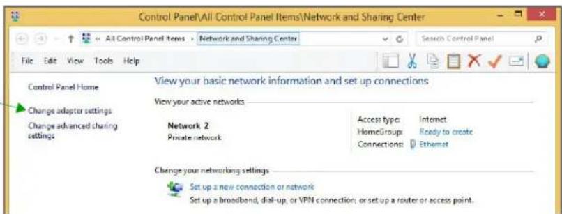
- Double-click the wired interface to your AV network, and then click the Properties button.
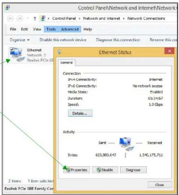
- Scroll down in the list to the Internet Protocol Version 4 (TCP/IPv4) option. Highlight it and click the Properties button.
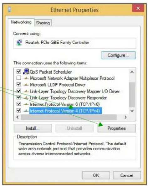
- Enable the Use the following IP address option, and enter the static IP address provided to you by your network administrator.


Note: If the computer does not need Internet access, you can simply enter a unique 169.254.xxx.xxx IP address with a 255.255.0.0 subnet mask. Contact your network administrator if you are unsure of how to configure the existing network. SVSi units will not self-assign in the 169.254.0.xxx range.
Note: If the computer has a statically-assigned IP address, click the Advanced button. Then click Add to enter a unique 169.254.xxx.xxx address with a subnet of 255.255.0.0.
STEP 2 CONNECTING DECODERS TO THE NETWORK
The digital connection from a Decoder DVI-D port (female) to a display is accomplished using either a DVI-D cable or HDMI (through adapter). N2000 units support embedded audio input and output on the DVI ports; however, some display devices (e.g., many monitors) do not support embedded audio. When using such a display, use the AUDIO port for separate transmission of sound and turn HDMI Audio off (on the Settings page) to avoid video display issues.
Power is supplied via a PoE-enabled switch or an external power supply. The N2211 is not a PoE device and must be powered by an external power supply. Refer to the following steps and Figure 2-5 for guidance.
- Using a Cat-5 cable, connect your SVSi Decoder's P0 port to a PoE-enabled switch. This provides both network and power connection. In non-PoE applications connect a 12V regulated power supply (N9312) to the two-pin terminal block plug connector (labeled +12V 2A).
- Connect the display you would like to use for that Decoder (monitor, projector, etc.) to the Decoder's DVI-D Output port using a DVI cable (or HDMI through adapter). This must be a digital video connection.

flowchart
graph TD
    A["SVSI"] --> B["N2000 Decoder"]
    B --> C["Cat-5"]
    C --> D["PoE-Enabled Switch"]
    E["DVI-D Cable (or HDMI through adapter)"] --> B
    F["Network"] --> D
Figure 2-5. Decoder Connections
- Repeat Steps 1 and 2 until all Decoders are installed on the network.
- Once the Decoders and displays are connected and powered up, the yellow LocalPlay screen appears on the displays.
Note: If the yellow LocalPlay screen does not appear, refer to Chapter 5, Troubleshooting for more guidance.

Note: In order for the unit to receive PoE, it must be connected to a switch or other equipment that has a PoE PSE (Power Sourcing Equipment) port. The N2211 Decoder is not a PoE device. When using this product, you must also provide power using the 12V external power supply (included in shipment). PoE does not pass through the daisy chain (P1) port.

Caution: Do not run wiring that is connected to a PoE PSE port outside of the building where the PSE resides. It is for intra-building use only.
STEP 3 CONNECTING ENCODERS TO THE NETWORK AND CONFIGURING STREAM SETTINGS
- Using a Cat-5 cable, connect your SVSi Encoder's P0 port to a PoE-enabled switch. In non-PoE applications connect a 12V regulated power supply (N9312) to the two-pin terminal block plug connector (labeled +12V 2A).

Note: In order for the unit to receive PoE, it must be connected to a switch or other equipment that has a PoE PSE port.
- In N-Able, select the Unit Management tab and click the Auto Discover button (if the table has not already populated itself with the installed units). See Figure 2-6.
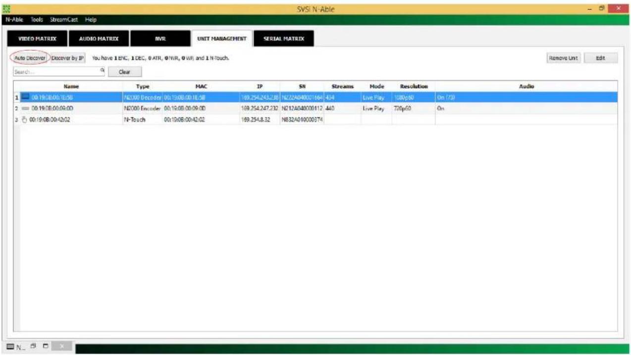
Figure 2-6. Unit Management Page
-
Find your Encoder in the list. N2000 units are displayed on the following tabs:
-
Unit Management tab — N2000 units have N2000 Encoder/Decoder listed in their Type fields.
• Video Matrix tab — N2000 units are found on the N2000 sub-tab (as shown in Figure 2-7).

Note: If using multiple Encoders in your set up, it is important to plug in and configure one Encoder at a time. All Encoders come pre-configured to use stream 1. As you add Encoders to the network, you will need to set them up to use different streams.
Encoders are listed across the top of the page.
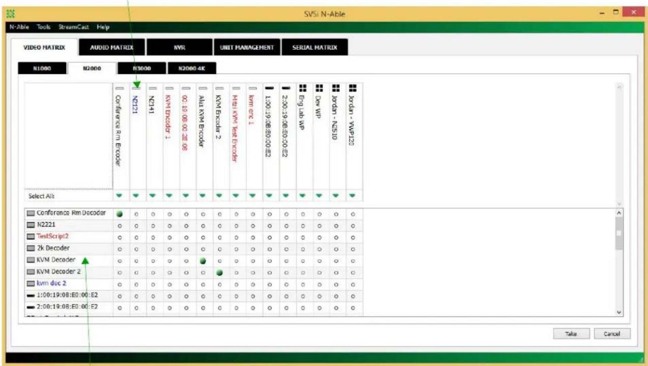
Decoders are listed down the left side of the page.
Red Text - No video source (encoder) or no display (decoder). Gray Text - Video output for this unit is disabled.
Black Text - Unit is in live play mode. Blue Text - Unit is playing locally-stored content.
Figure 2-7. Video Matrix Page
- Double-click the Encoder's name in the list. The N-Series Encoder Login page is displayed (see Figure 2-8). Use the following default login credentials to log in for the first time. These can be changed later on the Settings page.
Default username: admin Default password: password

Figure 2-8. Login Page

The Login page is only displayed if N-Able's stored username/password does not match the unit's username/password. A default system will match.
- The Settings page is displayed (see Figure 2-9).
- Change the Stream setting. We recommend setting Stream to a number between 2 and 254 (it is required that the number be less than 32,512).
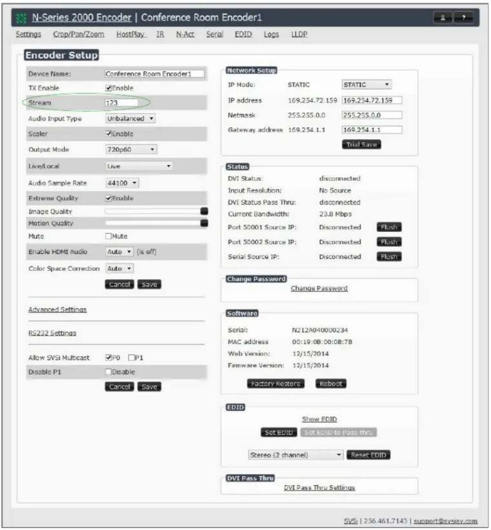
Figure 2-9. Changing Stream Setting
- Repeat these steps until all Encoders are connected to the network and configured with an appropriate Stream number.

Note: Each Encoder's Stream number must be unique to all other Encoders on the network.
Note: Screen-by-screen descriptions of the web interface options are provided for your reference in Chapter 3 Encoder Options and Chapter 4 Decoder Options.
STEP 4 CONFIGURING DECODER AND ENCODER IP ADDRESSES (IF NEEDED)
By default, all Decoders and Encoders are preset to Auto IP mode. This means that the IP address is pre-configured to 169.254.xxx.xxx with a subnet mask of 255.255.0.0. When an N2000 is first connected to the network, Auto IP checks the network for available IP addresses in the 169.254.xxx.xxx range and then makes an appropriate, static assignment to each unit. It may be beneficial in some applications to use DHCP (Dynamic Host Control Protocol) or static IP addresses, but IP configuration changes must be done correctly to avoid any communication disruptions with the N2000 unit.
How IP Address Changes Affect Unit Control
As discussed previously, N-Able control is dependent upon the host computer being in the same IP address range as the SVSi devices. Therefore, before making any N2000 IP address changes, we recommend having two statically-assigned IP addresses on your computer.
- Configure the first IP address to be in the range of the default N-Series IP settings (i.e., in the 169.254.xxx.xxx range), AND
- Configure a second IP address in the range of the IP address you are planning to assign to the units (or when using DHCP, an address within the defined range for your network).
Changing IP Addresses
There are two ways to assign new IP addresses to your N2000 units using N-Able:
- Option 1: Log in to each unit individually and make the changes on the Settings page.
- Option 2: Export a comma-separated value (CSV) file, make changes to all units in the resulting file, and import the CSV file into N-Able to apply the changes.
Option I: Assigning IP Addresses Individually (using the Settings page)
- Find the unit you wish to change in the control matrix (either on the Unit Management tab or the Video Matrix > N2000 tab).
- Double-click the unit and log in.
- Go to the Settings page and make IP address changes for that unit either by setting a STATIC address or by enabling DHCP (see Figure 2-10).
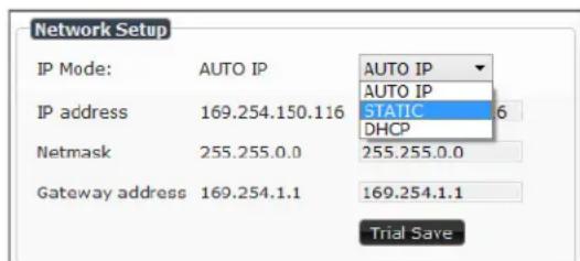
Figure 2-10. Network Setup Section of the Settings Page
- Click the Trial Save button.
- Return to the Settings page through the newly-configured IP address.
- Once the Settings page appears (successfully using the new IP address) click the Confirm button to lock in your changes.

Note: If you lose communication for any reason, unplug the N2000, wait one minute, and plug it back in. This restores the unit to the original IP address.
Option 2: Assigning IP Addresses to Multiple Units (using CSV files)
N-Able has the ability to export and import CSV files. Once units are auto-discovered in N-Able, the CSV file can be exported into Excel where parameters such as IP address, subnet mask, gateway, stream number, audio settings, etc. can be configured. Once configured, import the CSV file back into N-Able to assign those parameters to the appropriate devices. Reboot the devices to activate the new settings. This procedure can be used to configure multiple networked AV devices at the same time. It can also provide valuable diagnostics by allowing you to see the last known device configuration as well as scan the network for new devices (regardless of IP configuration).
To configure units using a CSV file, follow these steps:
- Make sure that you have performed an Auto Discover (on the Unit Management tab of N-Able) since connecting all of the new units to the network.
- From N-Able's main menu bar, select N-Able > Export CSV.
- Click Yes on the pop-up box informing you that a CSV file is about to be generated.

Note: A CSV file editor (e.g., Microsoft Excel) is necessary to proceed.
- The folder containing your CSV file displays. Double-click the file to open it.
- You can use this file to edit the IP mode, IP address, subnet mask, gateway IP address, stream number, etc. Once all changes have been made, save the file.
- Go back into N-Able and select N-Able > Import CSV.
- Browse to your saved CSV file and click Import.
STEP 5 CONNECTING ENCODERS TO AN INPUT SOURCE
Having already connected the Encoder(s) to the network and made the appropriate settings changes (as described in Step 3 and Step 4), you can now connect to the appropriate AV source(s). This connection from an Encoder DVI-I port (female) to an input source is accomplished using either a DVI-I cable or HDMI (through adapter).
-
Connect the source you would like to use for the Encoder (camera, laptop, etc.) to the Encoder's DVI-I Input port using a DVI-I cable (or HDMI through adapter). This connection can be digital or analog.
-
Repeat until all Encoders are connected to their sources.
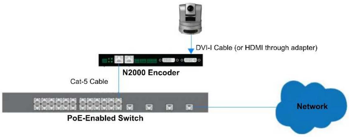
flowchart
graph TD
    A["Network"] --> B["N2000 Encoder"]
    B --> C["Cat-5 Cable"]
    B --> D["PoE-Enabled Switch"]
    B --> E["DVI-I Cable (or HDMI through adapter)"]
Figure 2-11. Encoder Connection to Source
SWITCHING AND SCALING OPTIONS
SVSi Encoders and Decoders make up a true AV matrix solution. In other words, one input can go to any or all outputs.
Both Encoders and Decoders have internal scaling capabilities. Keep the following in mind:
- The input of an Encoder is the video and/or audio signal going into the Encoder.
• The output of an Encoder is the network stream. - The input of a Decoder is the network stream.
- The output of a Decoder is the digital video and/or audio being transmitted out to the display device.
Seamless Switching
The N2000 Series supports seamless switching capability if the scalers in the Encoders are all set to the same resolution and refresh rate. If the scalers are off, all of the sources must have the same resolution and refresh rate.
To get streams onto a Decoder, use the Video Matrix tab to route video from an Encoder to a Decoder. This works seamlessly if the previously mentioned settings are true. All you have to do is click the common cell on the matrix, and click the Take button. See Figure 2-12 for an example.
Enabling this cell causes the Conference Rm Decoder to listen to the Conference Rm Encoder.

Figure 2-12. Seamless Switching Using the Video Matrix
CONTROL OPTIONS
For the most part, once the initial setup is complete, you will be primarily managing/configuring the Decoders. To better understand, think of Encoders as radio stations and Decoders as car radios. The Encoders are supplying the streams and, using the Decoders, you can “tune in” to the stream you want. SVSi’s N-Control solutions (N-Command, N-Act, and N-Touch) provide you with the most flexible management options available, insuring you are getting the most from your digital media system.
Primary Control Options
During initial configuration and setup, the free N-Able setup utility is sufficient. However, we do not recommend N-Able for production-level, primary-user control.
N-Command Controllers
These web-based hardware Controllers offer intuitive, powerful management of equipment, content, NVR recording/playback, bandwidth utilization, and AV switching (using a web-based, point-and-click graphical matrix).
The N-Command product line also offers:
- Simplified ASCII interface for third-party control via TCP/IP.
- Enterprise controller (N8012) has master/client failover protection and hot-swappable drives.
- Redundant power supplies.
• Graphical presentation of video network connections.
• Full configuration control: assign fixed IP addresses for each SVSi component, adjust variable bit-rate for each video stream, etc.
Visit our website and refer to Table 2-2 on page 35 for more details on the available N-Command Controllers.
Third-Party Controllers
The N2000 Series is capable of interfacing with third-party control systems such as Savant, Utelogy, AMX, Altinex, or Crestron. SVSi can provide Crestron modules which allow either direct control of each Encoder and Decoder or relayed commands through an N-Command controller. Contact SVSi support for third-party control modules.
Other Control Options
SVSi offers several simple solutions for convenient one touch (or no touch) device control. This includes touch panel as well as event-based commands used for controlling both SVSi products and third-party equipment.
N-Act | On-Board, Built-In Control
All N-Series Encoders and Decoders have on-board, built-in control capability via events that can trigger any number of TCP/UDP commands to other IP controllable devices. Included free with all N-Series Encoders/Decoders. See the section N-Act Page on page 61 for more information.
N-Touch | IP Wall Controller
This 240 x 320 capacitive touch display has Wi-Fi and Bluetooth for expanding control to mobile devices. Programming is done individually through the built-in web server or collectively to multiple units using an N-Command N8000 Series Controller. Multi-page custom graphics can be created using SVSi's free Panel Builder software (stored internally).
Software Bundles Included With N-Command
• Panel Builder: Build attractive touch panels to control the N2000 and third-party equipment.
• Wall Builder: Design walls of any size in minutes using SVSi's Encoders and Decoders.
Table 2-2. Management Options for the N2000 Series
| Features | N-Able Control Software | N-Touch Controller | N8001 Controller | N8002 Controller | N8012 Controller |
| Web-based Control | √ | √ | √ | √ | |
| Group Management | √ | √ | √ | ||
| Third-party Control | √ | √ | √ | √ | |
| Remote web-based Diagnostics | √ | √ | √ | ||
| Software Installation Not Required | √ | √ | √ | √ | |
| Virtual Matrix Switching | √ | √ | √ | √ | |
| Touch-panel editing and hosting | √ | √ | √ | √ | |
| Mobile devices supported | √ | √ | √ | √ | |
| Panel Builder | √ | √ | √ | √ | |
| Scripts | √ | √ | √ | √ | |
| Interface to Networked AV system | Host Network Interface | Network | Network | Dual Network Interfaces | Dual Network Interfaces |
| Redundant power supplies | √ | ||||
| Fail-over support | √ | ||||
| 1-yr Priority Help subscription | √ | ||||
| Max Number of Users | 1 | Unlimited | 5 | Unlimited | Unlimited |
| Max Number of Devices | Unlimited | Unlimited | 50 | Unlimited | Unlimited |
ENCODER INTRODUCTION
This chapter defines all of the configuration options available on your N2000 Series Encoders and is organized to reflect the graphical user interface (GUI) for ease of navigation.
ENCODER CONFIGURATION OPTIONS
From any main page in the internal web interface, you can access all other main pages by clicking the links in the top navigation bar. Figure 3-1 shows the main navigation bar and provides hot links to the sections of this chapter which describe them.

Figure 3-1. Section Links
SETTINGS PAGE
Click the Settings link at the top of any of the main web pages to access the page shown in Figure 3-2. This page is divided into several sections and also has links to other dialog boxes for additional configuration options. Refer to the following sections for detailed descriptions:
• Encoder Setup Section on page 38
• Advanced Settings on page 42
• RS232 Settings on page 46
• Network Setup Section on page 47
• Status Section on page 49
- Change Password on page 51
- Software Section on page 52
• EDID Section on page 53
• DVI Pass Thru Settings on page 55
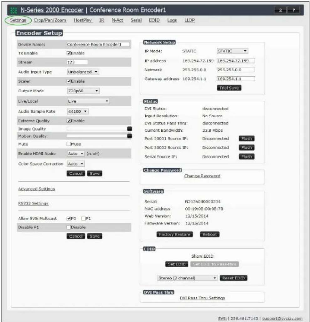
Figure 3-2. Settings Page
Encoder Setup Section
The Encoder Setup section of the Settings page is shown in Figure 3-3. Options are described in Table 3-1.
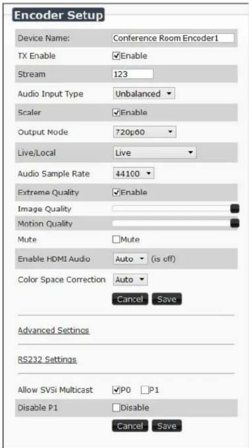
Figure 3-3. Encoder Setup Section
Table 3-1. Settings Page: Encoder Setup Section
| Option Description | Notes | |
| Device Name | Enter a user-friendly name for the unit. | More descriptive names in this field help you organize and manage the SVSi system efficiently. Names based on the unit's location and function are very useful. Some good examples are Lobby-Left-VGA (for left side of lobby, VGA input) or CR201-HDMI (for Conference Room 201, HDMI input). Keep in mind the matrices are organized alphanumerically. |
| TX Enable Enable to broadcast the AV signals. Disable to turn off/stop broadcasting. | Unit name appears in GREY text (in the Matrix) when this setting is disabled. | |
| Stream View/edit the current transmit stream number. | To better understand this setting, think of Encoders more like a channel on a cable box, rather than a traditional AV Matrix. Each Encoder must have a unique stream number, just like every channel must have a unique channel number (e.g., Food Network and HGTV cannot both be on channel 201). | |
| Audio Input Type | Select Unbalanced (single-ended) or Balanced analog audio input. | |
| Scaler Enable to scale | outgoing content to a fixed resolution or to use the Crop/Pan/Zoom functions. | |
| Output Mode | Select the output resolution of the video to be transmitted onto the network (the Scaler check box must be enabled for this to be applicable). | |
| Live/Local | Select live video or locally stored images for transmission onto the network. When video is not available, it automatically goes into local mode. | When video is not available, the most recently played local playlist is displayed. |
| Audio Sample Rate | Select the sample rate, in Hz, for the analog audio. | |
| Extreme Quality Enable | this check box to achieve best possible picture quality. | Enabling this option will increase your bandwidth, up to 200 Mbps per stream. Plan bandwidth accordingly. Enabling this option increases video quality only in situations where there are dense lines or dramatic color variations (e.g., a dense map or fully-populated spreadsheet). Can be disabled for most applications. |
| Image Quality Adjust the | compression level of the image. The further to the left on the slider, the more compression which will display as pixelization of the image. | When Extreme Quality is enabled, this slider's settings are not applied. |
| Motion Quality Adjust the | frame rate reduction. All the way to the right of the slider is 60 frames. As you slide left, you reduce frame rates. | The quickest way to reduce overall bandwidth is to reduce motion quality. However, this increases latency. |
| Mute Enable to stop the | transmission of audio data onto the network. | |
| Audio Source Set the | audio source to be disabled, enabled or selected automatically (see note). | The AUTO setting always corresponds to HDMI audio as long as there is an HDMI source. If the source is unplugged, it will automatically fall back to analog audio (if there is an analog source plugged in). |
| Color Space Correction | Set the color space settings for the Encoder (YcbCr, RGB) to be disabled, enabled, or selected automatically based on the source. | If you see a pink/green washed out screen (across the entire image), this can be changed by modifying color space settings. Most sources function with Auto selected but (for problematic sources) hard-set the value to what the source requires. It is best to do hard-set for all permanently installed sources (e.g., cameras, cable boxes, etc), but leave Auto on for periodic sources (e.g., laptop inputs). |
| Advanced Settings Refer to Advanced Settings on page 42 for details on the options available from this link. | ||
| RS232 Settings Refer to RS232 Settings on page 46 for details on the options available from this link. | ||
| Allow SVSi Multicast | Disable this option to prevent the port from outputting multicast video traffic. | Particularly useful if you are connecting a non-SVSi device to a port for network-based control. |
| Disable P1 Completely | disables the P1 port for all traffic. | Once disabled, anything connected to the P1 port will no longer be available on the network. |
| Cancel Click to return | all controls to the last saved configuration. | |
| Save Click to accept ch | changes made to these controls. | |
Advanced Settings
The section of the Settings page shown in Figure 3-4 is displayed when you click the Advanced Settings link. Options are described in Table 3-2.
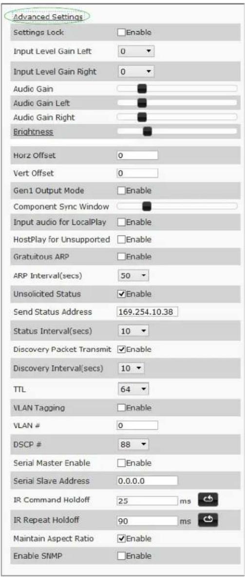
Figure 3-4. Advanced Settings
Table 3-2. Settings Page: Advanced Settings
| Option Description | Notes | |
| Settings Lock Enable | to lock the Encoder IP settings and stream number, preventing automated processes (from N-Able or N-Command) from occurring. | This does not prevent a control system from making changes or a user from manually making changes. |
| Input Level Gain Left/Right | Select a PRE-ENCODE cut in the audio signal. | This can help prevent distortion of the audio when the source is providing audio that is too loud/clipping. Setting does not affect digital audio. |
| Audio Gain Slide right | to provide a POST-ENCODE boost in the audio signal (to both left and right channel). | This can help compensate when the source is providing a weak audio signal. Does not affect digital audio. |
| Audio Gain Left Slide | right to provide a POST-ENCODE boost in the left channel's audio signal. | This can help compensate when the source is providing a weak audio signal. Does not affect digital audio. |
| Audio Gain Right Slide | right to provide a POST-ENCODE boost in the right channel's audio signal. | This can help compensate when the source is providing a weak audio signal. Does not affect digital audio. |
| Brightness Use sliders | to raise or lower RGB values of the Encoder (POST-ENCODE). | Only affects analog video. Does not affect digital video. |
| Horz Offset Enter the | number of pixels to shift the screen to the left. Range is -4 to 4 pixels. | The higher the number, the more to the left the screen will shift. Enter even numbers only to prevent red/blue color swapping. |
| Vert Offset | Enter the number of pixels to shift the screen up and down. Range is -100 to 100 pixels. | The higher the number, the higher the screen will shift. |
| Gen1 Output Mode | Enable when outputting to V-Series decoders. | |
| Component Sync Window | Use this slider to configure the sync on green sensitivity. | Used for computer video input to help with screen flickering. |
| Input audio for HostPlay | Enable to activate the input audio when the Live/Local menu is set to one of the local images. | |
| HostPlay for Unsupported | Enable to cause the Encoder to use a custom image whenever an unsupported video mode is supplied to it. | |
| Option | Description | Notes |
| Gratuitous ARP Enable | the Encoder to send a periodic Address Resolution Protocol (ARP) packet to the network. | |
| ARP Interval (secs) | Determine how often (in seconds) the unit transmits gratuitous ARP packets. | |
| Unsolicited Status Enable | the Encoder to send a periodic status packet to theSend Status Addressdescribed below. | |
| Send Status Address | WhenUnsolicited Statusis enabled, the Encoder sends a periodic status packet to the IP address specified here. | |
| Status Interval (secs) | Determine how often (in seconds) the unit transmits status packets. | |
| Discovery Packet Transmit | Enable the SVSi multicast discovery service (which is used to identify units). | This is useful for larger network integrations when broadcast packets will not cover the entire network. Enabled by default. |
| Discovery Interval (secs) | Determine how often (in seconds) the unit transmits discovery packets. | |
| TTL Select the Time To | Live (TTL) for the transmit audio and video streams. | Limits the lifespan of data on the transmit audio and video streams (to improve performance). |
| VLAN Tagging When enabled, tags the video and audio IP packet with the VLAN number. | ||
| VLAN # | Enter the VLAN number. | This number will be included in the video and audio IP packet whenVLAN Taggingis enabled. |
| DSCP # Select the Differentiated Services Code Point (DSCP) for the transmit audio and video streams. | ||
| Serial Master Enable | Enable this device to be the master to the designated client. | |
| Serial Client Address | Enter the IP address of the serial client device. | |
| Option Description | Notes | |
| IR Command Holdoff | Set the delay between IR command portions. The default setting is 25 ms. | IR commands are sent in two parts. This setting is the time (in milliseconds) between transmission of part one and part two. The second part of the command is inverted for confirmation purposes. |
| IR Repeat Holdoff Set | the repeat delay between IR commands. The default setting is 90 ms. | This is the amount of time before a new command is sent. For example, when pressing and holding the volume button on a remote control, this is how long until the command is repeated. |
| Maintain Aspect Ratio | When scalers are enabled, enabling this check box maintains the source's aspect ratio. | |
| Enable SNMP Enable to | to allow the device to handle Simple Network Management Protocol (SNMP) queries. | |
RS232 Settings
The section of the Settings page shown in Figure 3-5 is displayed when you click the RS232 Settings link. Options are described in Table3-3.

Figure 3-5. RS232 Settings
Table 3-3. Settings Page: RS232 Settings
| Option Description | |
| RS232 Baud Rate | Select the appropriate baud rate for the RS232 serial interface. Default is 9600. |
| RS232 Data Bits | Select the appropriate data bit count for the RS232 serial interface. Default is 8. |
| RS232 Parity | Select the appropriate parity for the RS232 serial interface. Default is no parity (none). |
| RS232 Stop Bits | Select the appropriate number of stop bits for the RS232 serial interface. Default is 1. |
Network Setup Section
The Network Setup section of the Settings page is shown in Figure 3-6. Options are described in Table 3-4.
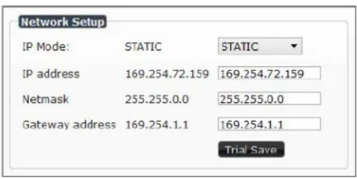
Figure 3-6. Network Setup Section
Table 3-4. Settings Page: Network Setup Section
| Option Description | Notes | |
| IP Mode Configure the | IP address mode. When set to AUTO IP, an IP Address in the range of 169.254.xxx.xxx with Netmask of 255.255.0.0 and Gateway address of 169.254.1.1 will be automatically assigned to the N2000 Encoder by the control software. When set to DHCP, an IP Address in the range of the DHCP server on the network will be automatically assigned to the N2000 Encoder. When set to STATIC, an IP address, Netmask, and Gateway address must be manually entered. | Using DHCP is generally not recommended. If the device is set to DHCP and fails to receive an address from the DHCP server in time, it will revert back to the AUTO IP Address (169.254.xxx.xxx) until the unit is rebooted. |
| IP address View the current IP address of the N2000 Encoder. When in STATIC mode, enter a new IP address into this field. | ||
| Netmask | View the current Netmask of the N2000 Encoder. When in STATIC mode, enter a new Netmask into this field. | |
| Gateway address | View the current Gateway address of the N2000 Encoder. When in STATIC mode, enter a new Gateway address into this field. | |
| Trial Save Click to initially save IP address changes. Once you log in to the unit using the new address, you will be able to confirm and accept the changes permanently. | ||
Status Section
The Status section of the Settings page is shown in Figure 3-7. Options are described in Table 3-5.
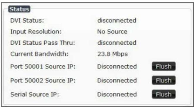
Figure 3-7. Status Section
Table 3-5. Settings Page: Status Section
| Option Description | Notes | |
| DVI Status Indicates if a video source is connected to the Encoder. | ||
| Input Resolution Indicates the video resolution of the currently connected source. | ||
| DVI Status Pass Thru | Indicates if a display device is connected to the Encoder. | |
| Current Bandwidth This is a snapshot of the unit as properties were loaded to the browser, not a live counter. Refresh the page to get an updated bandwidth. | ||
| Port 50001 Source IP | Shows the IP address of the currently connected device or displaysDisconnectedif no connection exists. | Port 50001 can only accept a single external connection at a time. If a device is currently showing the port occupied (by a control system or other device), then other connections will be rejected. However, connection attempts from the same IP will override the current connection. |
| Port 50002 Source IP | Shows the IP address of the currently connected device or displaysDisconnectedif no connection exists. | Port 50002 can only accept a single external connection at a time. If a device is currently showing the port occupied (by a control system or other device), then other connections will be rejected. However, connection attempts from the same IP will override the current connection. |
| Serial Source IP Shows | the IP address of the currently connected device or displaysDisconnectedif no connection exists. | Only a single external connection can be accepted on the port. If a device is currently showing the port occupied (by a control system or other device), then other connections will be rejected. However, connection attempts from the same IP will override the current connection. |
| Flush buttons These | buttons reset the port. | |
Change Password
To change the N2000 Encoder interface password, enter the current password in the field labeled Old Password, and enter a new password in the New Password and Confirm Password fields. Click Change PW to accept the new password.
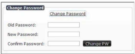
Figure 3-8. Change Password

This password needs to match N-Able's stored password to allow auto-login using N-Able.
Software Section
The Software section of the Settings page is shown in Figure 3-9. Options are described in Table 3-6.

Figure 3-9. Software Section
Table 3-6. Settings Page: Software Section
| Option Description | |
| Serial Displays the serial number of the N2000 Encoder. | |
| MAC Address | Displays the MAC address of the network interface of the N2000 Encoder. |
| Firmware Version | Displays the date code for the currently running version of the N2000 Encoder internal firmware. |
| Web Version | Displays the date code for the currently running version of the web interface. |
| Factory Restore | Click to restore the device to the original factory settings. This resets everything except the IP address (including name, stream number, serial settings, etc.). |
| Reboot | Click to reboot the device (does not affect current configuration). |
EDID Section
The EDID (Extended Display ID Data) section of the Settings page is shown in Figure 3-10. Options are described in Table 3-7.
Edit the Encoder's EDID if you need to change the device type it appears as to the source. There are two different ways to control the EDID of the Encoders.
Option 1: Use the default settings drop-down menu and select from the options available. Then click Reset EDID. This will work for most sources and is most often set to Stereo (2 channel).
Option 2: When using an EDID captured from a source connected to an Encoder, paste the data in to the white EDID block, overwriting existing EDID. Then click Set EDID.

The source will need to be disconnected while modifying EDID settings.


Figure 3-10. EDID Section
Table 3-7. Settings Page: EDID Section
| Option Description | |
| Show EDID | Click this link to view the Encoder's current EDID table. |
| Read local EDID | Click if source EDID has changed (refreshes the EDID table). |
| Set EDID If pasting a custom EDID, click to apply the changes. | |
| Set EDID Pass-thru | Set if you want to copy the current EDID to the Encoder's pass thru port. |
| Reset EDID | Choose a standard EDID from the drop-down menu and click Reset EDID to apply. |
DVI Pass Thru Settings
The section of the Settings page show in Figure 3-11 is displayed when you click the DVI Pass Thru Settings link. Options are described in Table 3-8.

Figure 3-11. DVI Pass Thru Settings
Table 3-8. Settings Page: DVI Pass Thru Settings
| Option Description | |
| DVI Pass Thru Enables | looped output. |
| Enable HDMI Audio | Determines if the unit will output audio over the HDMI connection. Selecting Auto bases audio output on the settings of the connected source device. |
| YCbCr 4:2:2 Output | For color conversion. Can force to RGB on set output based on connected device's reported settings. Default (and preferred setting) is Off. |
| Simplified DVI Detect | When enabled, detects DVI solely based on the hot plug detection. Enable to help prevent displays/monitors from going to sleep. |
| Invert DVI Sync | Inverts horizontal and vertical synchronization to the output display. Used for non-standard displays. |
| Cancel | Click to return all controls to the last saved configuration. |
| Save Click to accept changes made to these controls. | |
CROP/PAN/ZOOM PAGE
Click the Crop/Pan/Zoom link at the top of any of the main web pages to access the page shown in Figure 3-12. This page allows you to customize the viewable portion of the input. See Table 3-9 for option descriptions.

Figure 3-12. Crop/Pan/Zoom Page

Note: The Scaler check box must be enabled for changes on this page to take effect. See Table 3-1 on page 39 for more information.
Table 3-9. Crop/Pan/Zoom Page Options
| Option Description | |
| X1, Y1 Set pixel coordinates of viewing area (top left). | |
| X2, Y2 Set pixel coordinates of viewing area (bottom right). | |
| 16:9 Aspect Ratio Enable to force to a 16:9 ratio. | |
| No Crop | Click to disable existing crop settings and return unit to default output settings. |
| Execute Crop Reference | Click to execute changes. |
| Save Crop Reference | Click to save the current settings and store them as a preset for later use. Presets can be used by third-party controllers. |
| Stored Crop Presets | Use this section of the page to select/delete/export/import cropping presets. |
HOSTPLAY PAGE
Click the HostPlay link at the top of any of the main web pages to access the page shown in Figure 3-13. This page allows you to upload new images to the Encoders and configure the image playlists. The playlist will be shown on the display when no video is being transmitted or received. You can show a single image or set up multiple images to be displayed at a customized animation rate. See Table 3-10 for option descriptions.
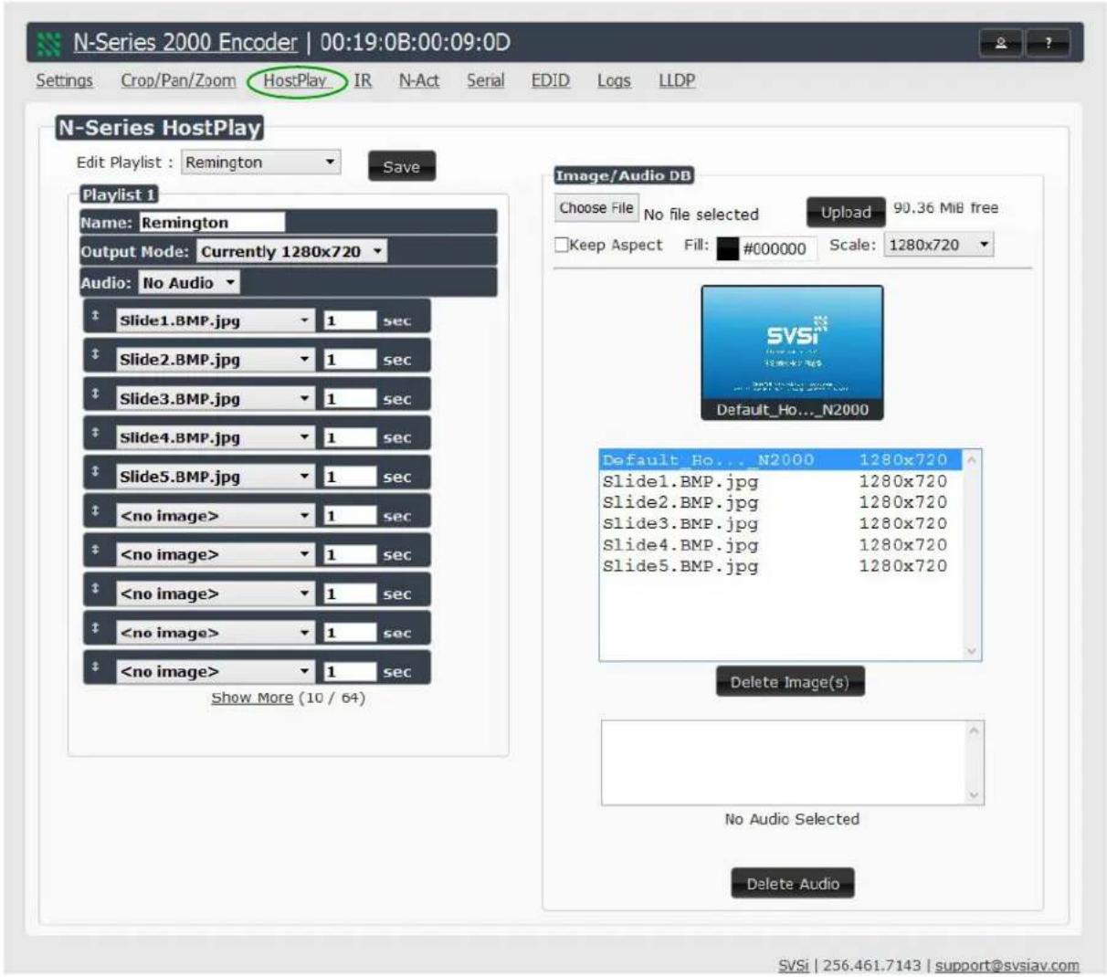
Figure 3-13. HostPlay Page
Table 3-10. HostPlay Page Options
| Option Description | |
| Edit Playlist | Select a playlist from the drop-down menu to view/edit the images currently used in the chosen image playlists. If more than one image appears in the list, a transition time can be set for each image. |
| Save Click to save the current configuration. | |
| Name Enter a name for the playlist. | |
| Output Mode | Select the HostPlay output resolution. The playlists that were uploaded in that resolution are then displayed for your selection. |
| Audio | Choose an audio file to play while the HostPlay image is on the screen. |
| Image list | Allows you to customize what images are displayed, the transition time for each image, etc. |
| Image/Audio DB | This section provides the ability to upload image and audio files to the N2000 Encoder database. You can also use the Fill field to customize the background color (used behind HostPlay images that do not take up the entire screen). |
| Delete Images | Delete the selected image file from the playlist. |
| Delete Audio | Delete the selected audio file from the playlist. |
IR PAGE
Click the IR link at the top of any of the main web pages to access the page shown in Figure 3-14. This page allows you to upload and execute IR Pronto codes so that other vendor's devices can be controlled through the Encoder's IR connector. Commands can be saved for future use and executed later. The IR Code menu lists all saved IR commands. See Table3-11 for option descriptions.
![N-Series 2000 Encoder | 00:19:0B:00:09:0D Settings Crop/Pan/Zoom HostPlay IR N-Act Serial EDID Logs LLDP N-Series IR Database IR Code: [New] Save Delete Execute SVSi | 256.461.7143 | support@svsiav.com](/content/2026/05/1044337/images/dbac3a06487ec0e7d20c69fe4eef4d517eded8bc02d2860742ba8df0bca9d35a.jpg)
Figure 3-14. IR Page
Table 3-11. IR Page Options
| Option Description | |
| IR Code | Create/select IR codes. Different vendors have different IR Pronto codes and can usually be found through a web search. Copy/paste new IR commands directly into the input space. |
| Save Save the current code. | |
| Delete Delete the current code. | |
| Execute | Activate the selected code through the Encoder's IR connector. |
N-ACT PAGE
Click the N-Act link at the top of any of the main web pages to access the page shown in Figure 3-15. This page allows you to create command lists which are performed automatically by the unit based on power or video connection (without the use of an outside controller). For example, you can tell a projector and lights to come on when the Encoder powers up. You can add multiple commands for each event. See Table 3-12 for option descriptions.

Figure 3-15. N-Act Page
Table 3-12. N-Act Page Options
| Option Description | |
| Enable Events Enable | to activate the configured events. |
| Power on Event | Create/delete/test events to be performed when the Encoder powers on. Visit our website for more details on Application Programming Interface (API) commands. |
| DVI Connected Event | Create/delete/test events to be performed when the Encoder is connected to a video source. The Trigger Delay field specifies how long the device has to be connected for the command to be executed. |
| DVI Disconnected Event | Create/delete/test events to be performed when the Encoder is disconnected from a video source. The Trigger Delay field specifies how long the device has to be disconnected for the command to be executed. This keeps accidental (momentary) disconnects from triggering the command sequence. |
| Save Events Click to save changes made to this page. | |
SERIAL PAGE
Click the Serial link at the top of any of the main web pages to access the page shown in Figure 3-16. This page allows you to upload and execute commands used for direct control of serial devices. Commands may be saved for future use and executed later. The Serial Code menu lists all saved commands. See Table 3-13 for option descriptions.

If the Port 5004/Serial Port is currently in use by another device, sending commands from the Serial page will always return a No Data message and fail to send the commands.
![N-Series 2000 Encoder | 00:19:0B:00:09:0D Settings Crop/Pan/Zoom HostPlay IR N-Act Serial EDID Logs LLDP N-Series Serial Database Serial Code: [New] Save Delete Execute ASCII: HEX: Response: SVSi | 256.461.7143 | support@svsiav.com](/content/2026/05/1044337/images/8343ecc76dfa028894350407f57f8cda59862b8fadb28b75570bf27bed4ab3f6.jpg)
Figure 3-16. Serial Page
Table 3-13. Serial Page Options
| Option Description | |
| Serial Code | Create/select serial commands. Different vendors have different codes that can usually be found through a web search. Copy/paste new commands (in either ASCII or HEX) directly into the appropriate input space. |
| Save Save the current code. | |
| Delete Delete the current code. | |
| Execute Apply the selected code to the Encoder's serial connection. | |
| ASCII and HEX | Paste serial commands directly into either the ASCII or HEX field. |
| Response | View responses provided by the device receiving the serial command(s). |
EDID PAGE
Click the EDID link at the top of any of the main web pages to access the page shown in Figure 3-17. Every display has stored information that it communicates to the output device. This page allows you to view that information. See Table 3-14 for option descriptions.

Figure 3-17. EDID Page
Table 3-14. EDID Page Options
| Option Description | |
| Pass-thru | Displays EDID information for the display connected to the Encoder's pass thru port. |
| Local | Displays EDID information for the Encoder. This information is being provided to the source connected to the Encoder. |
LOGS PAGE
Click the Logs link at the top of any of the main web pages to access the page shown in Figure 3-18. The Logs page displays a command log that lists all TCP and UDP messages the unit receives. It also displays the web browser's IP address and gives you options to Refresh and Reset Logs.
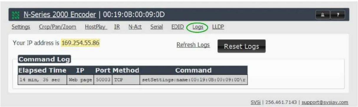
Figure 3-18. Logs Page
LLDP PAGE
Click the LLDP link at the top of any of the main web pages to access the page shown in Figure 3-19. The LLDP page displays information from the Link Layer Discover Protocol (LLDP) packet which identifies the port number and switch the device is connected to.

Figure 3-19. LLDP Page
DECODER INTRODUCTION
This chapter defines all of the configuration options available on your N2000 Series Decoders and is organized to reflect the graphical user interface (GUI) for ease of navigation.
DECODER CONFIGURATION OPTIONS
As explained in the previous chapter, you can access the GUI main pages by clicking the links in the top navigation bar. Figure 4-1 shows the main navigation bar for the Decoder and provides hot links to the sections of this chapter which describe them.

Figure 4-1. Section Links
SETTINGS PAGE
Click the Settings link at the top of any of the main web pages to access the page shown in Figure 4-2. This page is divided into several sections and also has links to other dialog boxes for additional configuration options. Refer to the following sections for detailed descriptions:
• Decoder Setup Section on page 70
- Advanced Settings on page 73
• RS232 Settings on page 77
• Network Setup Section on page 78
• Status Section on page 80
- Change Password on page 82
- Software Section on page 83
• EDID Section on page 84
• Audio Downmixer Settings on page 85

Figure 4-2. Settings Page
Decoder Setup Section
The Decoder Setup section of the Settings page is shown in Figure 4-3. Options are described in Table 4-1.

Figure 4-3. Decoder Setup Section
Table 4-1. Settings Page: Decoder Setup Section
| Option Description | Notes | |
| Device Name | Enter a user-friendly name for the unit. | More descriptive names in this field help you organize and manage the SVSi system efficiently. Names based on the unit's location and function are very useful. Some good examples are Lobby-Left-VGA (for left side of lobby, VGA input) or CR201-HDMI (for Conference Room 201, HDMI input). Keep in mind the matrices are organized alphanumerically. |
| Option | Description | Notes |
| Stream View/edit the current transmit stream number. | To better understand this setting, think of Decoders more like a channel on a cable box, rather than a traditional AV Matrix. Each Decoder must have a unique stream number, just like every channel must have a unique channel number (e.g., Food Network and HGTV cannot both be on channel 201). | |
| Audio Stream View/edit the current audio receive stream number. | ||
| Audio Follows Video | Enable to force the Audio Stream to the same as the video stream. | |
| Scaler Enable to scale | outgoing content to a fixed resolution or to use the Crop/Pan/Zoom functions. | |
| Output Mode Select the output resolution of the video to be transmitted to the video output device (e.g., LCD) (the Scaler check box must be enabled for this to be applicable). | ||
| Live/Local Select live video or locally stored images for transmission to the video output device (e.g., LCD). When video is not available, it automatically goes into local mode. | When video is not available, the most recently played local playlist is displayed. | |
| Mute Enable to mute output audio. | ||
| Lineout Volume This slider controls the output gain on the analog audio output. By default, it controls both the left and right lineout channels. Click the Set Left/Right link to control channels individually. | ||
| Enable HDMI Audio | ON forces audio on at all times. AUTO reads the EDID of the connected device to determine whether or not to send audio. | |
| Advanced Settings | Refer to Advanced Settings on page 73 for details on the options available from this link. | |
| RS232 Settings | Refer to RS232 Settings on page 77 for details on the options available from this link. | |
| Option Description | Notes | |
| Allow SVSi Multicast | Disable this option to prevent the port from outputting multicast video traffic. | Particularly useful if you are connecting a non-SVSi device to a port for network-based control. |
| Disable P1 Completely | disables the P1 port for all traffic. | Once disabled, anything connected to the P1 port will no longer be available on the network. |
| Cancel Click to return | all controls to the last saved configuration. | |
| Save Click to accept ch | changes made to these controls. | |
Advanced Settings
The section of the Settings page shown in Figure 4-4 is displayed when you click the Advanced Settings link. Options are described in Table 4-2.
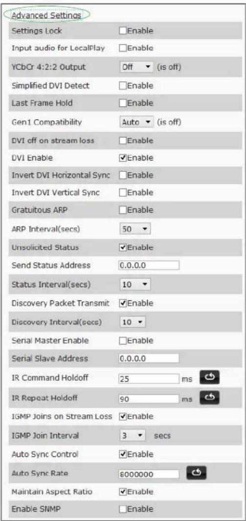
Figure 4-4. Advanced Settings
Table 4-2. Settings Page: Advanced Settings
| Option Description | Notes | |
| Settings Lock Enable to lock the Decoder IP settings and stream number, preventing automated processes (from N-Able or N-Command) from occurring. | This does not prevent a control system from making changes or a user from manually making changes. | |
| Input audio for LocalPlay | Select to enable the input audio when the Live/Local menu is set to one of the local images. | |
| YCbCr 4:2:2 Output Set YCbCr output to be disabled, enabled, or selected automatically based on the connected display. | ||
| Simplified DVI Detect | Select to enable the detection of a display device using a simple line level check. | |
| Last Frame Hold Select to cause the Encoder to continue playing the last valid video frame if the network connection is lost. | When enabled, Local Play will not appear. | |
| Gen 1 Compatibility Set compatibility with the color space of legacy equipment to be disabled, enabled, or selected automatically based on the identifying information in the video stream. | ||
| DVI off on stream loss | Select to disable the video output drive when the video stream is not available. | |
| DVI Enable Select to enable output video. | ||
| Invert DVI Horizontal Sync | Select to invert the polarity of the horizontal sync signal driven to the display device. | |
| Invert DVI Vertical Sync | Select to invert the polarity of the vertical sync signal driven to the display device. | |
| Gratuitous ARP Enable the Decoder to send a periodic Address Resolution Protocol (ARP) packet to the network. | ||
| ARP Interval (secs) | Determine how often (in seconds) the unit transmits gratuitous ARP packets. | |
| Unsolicited Status | Enable the Decoder to send a periodic status packet to the Send Status Address described below. | |
| Send Status Address | When Unsolicited Status is enabled, the Decoder sends a periodic status packet to the IP address specified here. | |
| Status Interval (secs) | Determine how often (in seconds) the unit transmits status packets. | |
| Discovery Packet Transmit | Enable the SVSi multicast discovery service (which is used to identify units). | This is useful for larger network integrations when broadcast packets will not cover the entire network. Enabled by default. |
| Discovery Interval (secs) | Determine how often (in seconds) the unit transmits discovery packets. | |
| Serial Master Enable | Enable this device to be the master to the designated client. | |
| Serial Client Address | Enter the IP address of the serial client device. | |
| IR Command Holdoff | Set the delay between IR command portions. The default setting is 25 ms. | IR commands are sent in two parts. This setting is the time (in milliseconds) between transmission of part one and part two. The second part of the command is inverted for confirmation purposes. |
| IR Repeat Holdoff Set | the repeat delay between IR commands. The default setting is 90 ms. | This is the amount of time before a new command is sent. For example, when pressing and holding the volume button on a remote control, this is how long until the command is repeated. |
| IGMP Joins on Stream Loss | Enable to send Internet Group Management Protocol (IGMP) join messages when no incoming stream is detected. | |
| IGMP Join Interval Delay in seconds between sending IGMP join messages (if IGMP Joins on Stream Loss is enabled). | ||
| Auto Sync Control Enable synchronization of vertical sync with the network. | Enable this option when using multiple Decoders (e.g, when building a video wall) that must be synchronized together. | |
| Auto Sync Rate Set the rate at which the vertical sync adjusts. | ||
| Maintain Aspect Ratio | When scalers are enabled, enabling this check box maintains the source's aspect ratio. | |
| Enable SNMP Enable to allow the device to send Simple Network Management Protocol (SNMP) packets. | ||
RS232 Settings
The section of the Settings page shown in Figure 4-5 is displayed when you click the RS232 Settings link. Options are described in Table4-3.

Figure 4-5. RS232 Settings
Table 4-3. Settings Page: RS232 Settings
| Option Description | |
| RS232 Baud Rate | Select the appropriate baud rate for the RS232 serial interface. Default is 9600. |
| RS232 Data Bits | Select the appropriate data bit count for the RS232 serial interface. Default is 8. |
| RS232 Parity | Select the appropriate parity for the RS232 serial interface. Default is no parity (none). |
| RS232 Stop Bits | Select the appropriate number of stop bits for the RS232 serial interface. Default is 1. |
Network Setup Section
The Network Setup section of the Settings page is shown in Figure 4-6. Options are described in Table 4-4.

Figure 4-6. Network Setup Section
Table 4-4. Settings Page: Network Setup Section
| Option Description | Notes | |
| IP Mode Configure the | IP address mode. When set to AUTO IP, an IP Address in the range of 169.254.xxx.xxx with Netmask of 255.255.0.0 and Gateway address of 169.254.1.1 will be automatically assigned to the N2000 Decoder by the control software. When set to DHCP, an IP Address in the range of the DHCP server on the network will be automatically assigned to the N2000 Decoder. When set to STATIC, an IP address, Netmask, and Gateway address must be manually entered. | Using DHCP is generally not recommended. If the device is set to DHCP and fails to receive an address from the DHCP server in time, it will revert back to the AUTO IP Address (169.254.xxx.xxx) until the unit is rebooted. |
| IP address View the current IP address of the N2000 Decoder. When in STATIC mode, enter a new IP address into this field. | ||
| Netmask | View the current Netmask of the N2000 Decoder. When in STATIC mode, enter a new Netmask into this field. | |
| Gateway address | View the current Gateway address of the N2000 Decoder. When in STATIC mode, enter a new Gateway address into this field. | |
| Trial Save Click to initially save IP address changes. Once you log in to the unit using the new address, you will be able to confirm and accept the changes permanently. | ||
Status Section
The Status section of the Settings page is shown in Figure 4-7. Options are described in Table 4-5.
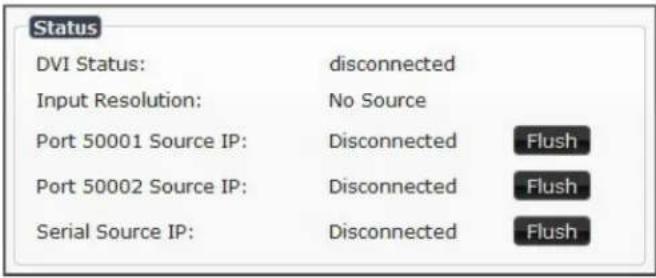
Figure 4-7. Status Section
Table 4-5. Settings Page: Status Section
| Option Description | Notes | |
| DVI Status Indicates if | video is connected to the Decoder. | |
| Input Resolution Indicates the video resolution of the incoming video source. | ||
| Port 50001 Source IP | Shows the IP address of the currently connected device or displaysDisconnectedif no connection exists. | Port 50001 can only accept a single external connection at a time. If a device is currently showing the port occupied (by a control system or other device), then other connections will be rejected. However, connection attempts from the same IP will override the current connection. |
| Port 50002 Source IP | Shows the IP address of the currently connected device or displaysDisconnectedif no connection exists. | Port 50002 can only accept a single external connection at a time. If a device is currently showing the port occupied (by a control system or other device), then other connections will be rejected. However, connection attempts from the same IP will override the current connection. |
| Serial Source IP Shows | the IP address of the currently connected device or displaysDisconnectedif no connection exists. | Only a single external connection can be accepted on the port. If a device is currently showing the port occupied (by a control system or other device), then other connections will be rejected. However, connection attempts from the same IP will override the current connection. |
| Flush buttons These | buttons reset the port. | |
Change Password
To change the N2000 Decoder interface password, enter the current password in the field labeled Old Password, and enter a new password in the New Password and Confirm Password fields. Click Change PW to accept the new password.

Figure 4-8. Change Password

This password needs to match N-Able's stored password to allow auto-login using N-Able.
Software Section
The Software section of the Settings page is shown in Figure 4-9. Options are described in Table 4-6.

Figure 4-9. Software Section
Table 4-6. Settings Page: Software Section
| Option Description | |
| Serial Displays the serial number of the N2000 Decoder. | |
| MAC Address | Displays the MAC address of the network interface of the N2000 Decoder. |
| Web Version | Displays the date code for the currently running version of the web interface. |
| Firmware Version | Displays the date code for the currently running version of the N2000 Decoder internal firmware. |
| Factory Restore | Click to restore the device to the original factory settings. This resets everything except the IP address (including name, stream number, serial settings, etc.). |
| Reboot | Click to reboot the device (does not affect current configuration). |
EDID Section
The section of the Settings page shown in Figure 4-10 is displayed when you click the Show EDID link. This section displays the EDID of the output device connected to the Decoder.
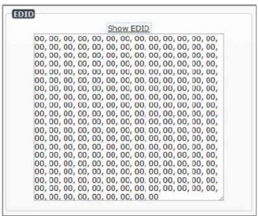
Figure 4-10. EDID Section
Audio Downmixer Settings
The section of the Settings page shown in Figure 4-11. is displayed when you click the Audio Downmixer Settings link. Options are described in Table 4-7.

Figure 4-11. Audio Downmixer Settings
Table 4-8. Settings Page: Audio Downmixer Settings
| Option Description | |
| Enable HDMI Downmix | Set HDMI audio downmixing to be disabled, enabled, or selected automatically when receiving a 7.1 audio source. |
| Center Gain slider | Set percentage of audio on center channel mixed into left and right output when downmixing. |
| Front Gain slider | Set percentage of audio on front left and right channels mixed into left and right output (respectively). |
| Surround Gain slider | Set percentage of audio on surround when downmixing left and right channels mixed into left and right output (respectively). |
| Line out source | Select a line out source or selectDownmixwhen using the downmixer. |
| Cancel | Click to return all controls to the last saved configuration. |
| Save Click to accept changes made to these controls. | |
| Defaults | Click to return all controls to their default settings. |
CROP/PAN/ZOOM PAGE
Click the Crop/Pan/Zoom link at the top of any of the main web pages to access the page shown in Figure 4-12. This page allows you to customize the viewable portion of the input. See Table 4-9 for option descriptions.

Figure 4-12. Crop/Pan/Zoom Page
Table 4-9. Crop/Pan/Zoom Page Options
| Option Description | |
| X1, Y1 Set pixel coordinates of viewing area (top left). | |
| X2, Y2 Set pixel coordinates of viewing area (bottom right). | |
| 16:9 Aspect Ratio Enable to force to a 16:9 ratio. | |
| No Crop | Click to disable existing crop settings and return unit to default output settings. |
| Execute Crop Reference | Click to execute changes. |
| Save Crop Reference | Click to save the current settings and store them as a preset for later use. Presets can be used by third-party controllers. |
| Stored Crop Presets | Use this section of the page to select/delete/export/import cropping presets. |
LOCALPLAY PAGE
Click the LocalPlay link at the top of any of the main web pages to access the screen shown in Figure 4-13. This page allows you to upload new images to the Decoders and configure the image playlists. The playlist will be shown on the display when no video is being transmitted or received. You can show a single image or set up multiple images to be displayed at a customized animation rate. See Table 4-11 for option descriptions.

Figure 4-13. LocalPlay Page
Table 4-11. LocalPlay Page Options
| Option Description | |
| Edit Playlist | Select a playlist from the drop-down menu to view/edit the images currently used in the chosen image playlists. If more than one image appears in the list, a transition time can be set for each image. |
| Save Click to save the | current configuration. |
| Name View/edit playlist | names. |
| Output Mode | Select the resolution you want the image(s) to play in. |
| Audio | Select an audio file to play while the LocalPlay image is on the screen. |
| Image List | Allows you to customize what images are displayed, the transition time for each image, etc. |
| Image/Audio DB | This section allows you to upload images to the N2000 Decoder image database. You can also use the Fill field to customize the background color (used behind LocalPlay images that do not take up the entire screen). |
| Delete Image(s) | Delete the selected image file from the playlist. |
| Delete Audio | Delete the selected audio file from the playlist. |
IR PAGE
Click the IR link at the top of any of the main web pages to access the page shown in Figure 4-14. This page allows you to upload and execute IR Pronto codes so that other vendor's devices can be controlled through the Decoder's IR connector. Commands can be saved for future use and executed later. The IR Code menu lists all saved IR commands. See Table4-12 for option descriptions.

Figure 4-14. IR Page
Table 4-12. IR Page Options
| Option Description | |
| IR Code | Create/select IR codes. Different vendors have different IR Pronto codes and can usually be found through a web search. Copy/paste new IR commands directly into the input space. |
| Save Save the current code. | |
| Delete Delete the current code. | |
| Execute | Activate the selected code through the Decoder's IR connector. |
N-ACT PAGE
Click the N-Act link at the top of any of the main web pages to access the page shown in Figure 4-15. This page allows you to create command lists which are performed automatically by the unit based on power or video connection (without the use of an outside controller). For example, you can tell a projector and lights to come on when the Decoder powers up. You can add multiple commands for each event. See Table 4-13 for option descriptions.

Figure 4-15. N-Act Page
Table 4-13. N-Act Page Options
| Option Description | |
| Enable Events Enable | to activate the configured events. |
| Power on Event | Create/delete/test events to be performed when the Decoder powers on. Visit our website for more details on Application Programming Interface (API) commands. |
| DVI Connected Event | Create/delete/test events to be performed when the Decoder is connected to an output display. The Trigger Delay field specifies how long the device has to be connected for the command to be executed. |
| DVI Disconnected Event | Create/delete/test events to be performed when the Decoder is disconnected from the output display. The Trigger Delay field specifies how long the device has to be disconnected for the command to be executed. This keeps accidental (momentary) disconnects from triggering the command sequence. |
| Save Events Click to save changes made to this page. | |
SERIAL PAGE
Click the Serial link at the top of any of the main web pages to access the page shown in Figure 4-16. This page allows you to upload and execute commands used for direct control of serial devices. Commands may be saved for future use and executed later. The Serial Code menu lists all saved commands. See Table 4-14 for option descriptions.

If the Port 5004/Serial Port is currently in use by another device, sending commands from the Serial page will always return a No Data message and fail to send the commands.

Figure 4-16. Serial Page
Table 4-14. Serial Page Options
| Option Description | |
| Serial Code | Create/select serial commands. Different vendors have different codes that can usually be found through a web search. Copy/paste new commands (in either ASCII or HEX) directly into the appropriate input space. |
| Save Save the current code. | |
| Delete Delete the current code. | |
| Execute | Send the selected code out the Decoder's serial connection. |
| ASCII and HEX | Paste serial commands directly into either the ASCII or HEX field. |
| Response | View responses provided by the device receiving the serial command(s). |
EDID PAGE
Click the EDID link at the top of any of the main web pages to access the page shown in Figure 4-17. Every display has stored information that it communicates to the output device. This page allows you to view the EDID information of the connected output display.
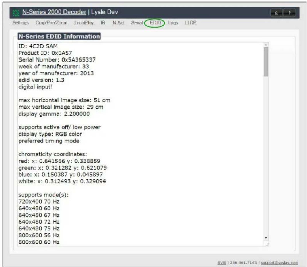
Figure 4-17. EDID Page
LOGS PAGE
Click the Logs link at the top of any of the main web pages to access the page shown in Figure 4-18. The Logs page displays a command log that lists all TCP and UDP messages the unit receives. It also displays the unit's IP address and gives you options to Refresh and Reset Logs.

Figure 4-18. Logs Page
LLDP PAGE
Click the LLDP link at the top of any of the main web pages to access the page shown in Figure 4-19. The LLDP page displays information from the Link Layer Discover Protocol (LLDP) packet which identifies the port number and switch the device is connected to.

Figure 4-19. LLDP Page
INTRODUCTION
This chapter contains possible solutions to some common issues. Should you encounter any problems not covered by these guidelines, please contact SVSi technical support via email (support@svsiav.com) or call 256.461.7143 x9900. You can also visit our support webpage at support.svsiav.com.
Table 5-1. Troubleshooting Suggestions
| Issues Suggestions | |
| LocalPlay graphic displays instead of the stream from the Encoder. | Verify Decoder is assigned to view a valid stream (of an active Encoder).Verify Decoder is currently inLivePlaymode (its name will display in black text on theVideo Matrixpage). You can change toLivemode on theSettingspage (seeTable 4-1on page 70 for more details).Verify network is properly configured and set up. If needed, connect Encoder's network port to Decoder to bypass the network. |
| HostPlay graphic displays instead of the video from the source. | Verify Encoder is inLivePlaymode (its name will display in black text on theVideo Matrixpage). You can change toLivemode on theSettingspage (seeTable 3-1on page 39 for more details).Verify source is attached and is outputting a valid signal (DVI LED on Encoder is on). |
| Unsupported Resolution graphic displays. | Change source resolution to a valid resolution (try 720p60).Verify cabling is correct. |
| Copy Protected Content screen displays. | Contact SVSi technical support. |
| Black screen/no graphic displays. | Set Decoder toLocalPlay. If theLocalPlaygraphic does not appear, check the display input settings and cabling. As mentioned previously in this table, you can change to theLocalmode on the Decoder's Settings page.IfLocalPlayappears, set Decoder to live play and verify network is configured properly. |
| No audio is detected. • If there is no audio on all ____ Decoders, verify audio settings are correct on Encoder.• If there is no audio on a single Decoder, verify audio settings are correct on Decoder. | |
| Device has been discovered in N-Able, but the configuration pages do not open when double-clicking device name on the Video Matrix page. | Make sure your computer is in the same IP address range as the unit. See Setting Up Your Host Computer on page 21 for more information. |
| When changing the audio type, there are problems with audio in/out. | Check the Audio Source and HDMI Audio settings on the Settings page. For example, if you are trying to change the audio type to make the input of the Encoder HDMI embedded audio in/analog audio out from the Decoder, these settings cannot be set to Auto. Set the Encoder to Audio Source >ON (embedded digital audio on DVI connection) and the Decoder to HDMI Audio >OFF (analog output on the Phoenix connection). |
| Not receiving audio. | Check that the Decoder has proper audio stream setting (typically Audio follows Video). |
| Not receiving analog video through the Encoder. | Make sure that analog converter is in a DVI-I pin-out. Note: All SVSi outputs are digital-only (DVI pass-thru on Encoder and DVI output on Decoder). ORIf using a Y cable (N9420) and an HDMI source is already connected to the Encoder, disconnect the HDMI source. Encoders give preference to HDMI and will not allow analog signal to pass while it is connected. |
| Video output is stuttering. | This could be a network bandwidth issue where the full video stream is not reliably getting from Encoder to Decoder. Contact your network administrator for assistance. |
| Experiencing a red/blue color swap. | Check Gen1 Compatibility Mode. If the entire system is N-Series, set to Off. If the system is mixed (V-Series and N-Series), set to On for the N-Series Decoder. See Advanced Settings on page 73 for more information on this mode. |
| Serial port is not working as expected. | Verify the RS232 Settings on the Settings page. Flush the serial port on the Settings page if another device is connected.Connecting the Tx and Rx pins on the RS232 connector creates a loopback that could also help when troubleshooting. |


- Table of Contents
- Chapter I. Introduction
- Chapter 2. Installation
- Chapter 3. Encoder Options
- Chapter 4. Decoder Options
- Chapter 5. Troubleshooting
- Trademarks
- To the Reader
- Conventions
- Safety Instructions
- Disclaimer
- FCC Class A Notice
- Service and Warranty
- PRODUCT OVERVIEW
- HD AV over IP Series
- N2121 HD AV over IP Encoder
- N2211 HD AV over IP Decoder (non-PoE)
- N2221 HD AV over IP Decoder
- Low-Latency AV over IP Series
- N2141 Low-Latency AV over IP Encoder
- N2241 Low-Latency AV over IP Decoder
- REAR PANEL PORTS AND LEDS
- APPLICATION EXAMPLES
- INTRODUCTION
- INSTALLATION OVERVIEW
- MOUNTING OPTIONS
- Surface and Wall Mounting
- Rack Mounting Options
- N2000 Series Stand-Alone Units
- N2000 Series Cards
- STEP-BY-STEP INSTALLATION INSTRUCTIONS
- There are PoE switches operational on the network.
- Deployment considerations have been made for the addition of high-speed video.
- You loaded N-Able onto the computer you are using to configure the equipment.
- STEP I SETTING UP YOUR HOST COMPUTER
- STEP 2 CONNECTING DECODERS TO THE NETWORK
- STEP 3 CONNECTING ENCODERS TO THE NETWORK AND CONFIGURING STREAM SETTINGS
- STEP 4 CONFIGURING DECODER AND ENCODER IP ADDRESSES (IF NEEDED)
- How IP Address Changes Affect Unit Control
- Changing IP Addresses
- Option I: Assigning IP Addresses Individually (using the Settings page)
- Option 2: Assigning IP Addresses to Multiple Units (using CSV files)
- STEP 5 CONNECTING ENCODERS TO AN INPUT SOURCE
- SWITCHING AND SCALING OPTIONS
- Seamless Switching
- CONTROL OPTIONS
- Primary Control Options
- N-Command Controllers
- Third-Party Controllers
- Other Control Options
- N-Act | On-Board, Built-In Control
- N-Touch | IP Wall Controller
- Software Bundles Included With N-Command
- ENCODER INTRODUCTION
- ENCODER CONFIGURATION OPTIONS
- SETTINGS PAGE
- Encoder Setup Section
- Advanced Settings
- RS232 Settings
- Network Setup Section
- Status Section
- Change Password
- Software Section
- EDID Section
- DVI Pass Thru Settings
- CROP/PAN/ZOOM PAGE
- HOSTPLAY PAGE
- IR PAGE
- N-ACT PAGE
- SERIAL PAGE
- EDID PAGE
- LOGS PAGE
- LLDP PAGE
- DECODER INTRODUCTION
- DECODER CONFIGURATION OPTIONS
- Decoder Setup Section
- Audio Downmixer Settings
- LOCALPLAY PAGE
Brand : AMX
Model : NMX-DEC-N2211
Category : Audiovisual Equipment