
MI-15010 - Office Mount-It! - Free user manual and instructions
Find the device manual for free MI-15010 Mount-It! in PDF.

| Product Type | Electric Sit-Stand Corner Desk |
| Brand | Mount-It! |
| Model | MI-15010 |
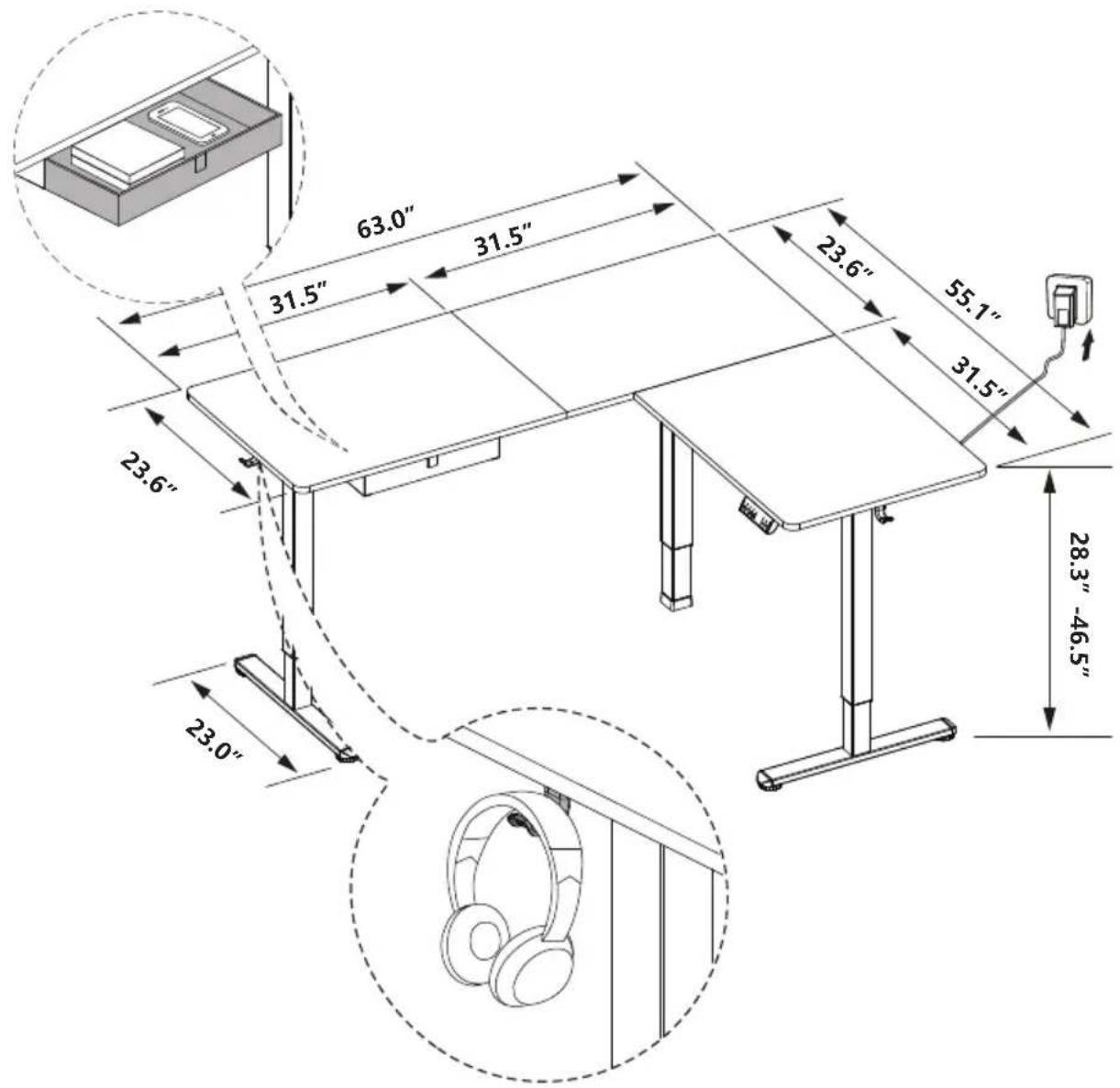
| Height Range | 28.3" to 46.5" (72 cm to 118 cm) |
| Load Capacity | 176 lbs (80 kg) |
| Speed | 20 mm/s |
| Noise Level | < 55 dB |
| Power Input | 110V-240V |
| Memory Presets | 3 (buttons 1, 2, 3) |
| Collision Detection | Adjustable sensitivity (Off, Low, Normal, High) |
| Display Units | Inches (IN) or Metric (SI) |
| Controller Type | Digital control panel with S button and preset buttons |
| Motor Protection | Overheating protection (2 min continuous use, 18 min cooldown) |
| Error Codes | Hot, EI0, E20, E02, E32, E31, E60, - (cable disconnect) |
| Cable Management | Included cable holder and cable clips |
| Accessories | Cloth drawer, headphone hooks, side plates, feet, rubber pads |
| Desktop Configuration | Three-piece L-shaped corner desk (A1, A2, A3) |
| Assembly Required | Yes, detailed step-by-step instructions included |
| Warranty | Visit mount-it.com for product registration and warranty information |
| Customer Support | Phone: (855) 925-5668, Mon-Fri 8am-4pm PST; Email: support@mount-it.com |
Frequently Asked Questions - MI-15010 Mount-It!
User questions about MI-15010 Mount-It!
0 question about this device. Answer the ones you know or ask your own.
Ask a new question about this device
Download the instructions for your Office in PDF format for free! Find your manual MI-15010 - Mount-It! and take your electronic device back in hand. On this page are published all the documents necessary for the use of your device. MI-15010 by Mount-It!.
USER MANUAL MI-15010 Mount-It!
natural_image
Line drawing of a two-level office desk with legs and chairs (no text or symbols)
Please scan this QR code to visit the product page
Extra Large Corner Sit Stand Desk

HAVE QUESTIONS?
Monday - Friday from 8:00am - 4:00pm PST

support@mount-it.com

(855) 925-5668

www.mount-it.com
Thank you for choosing Mount-It!
EN

Read the entire instruction manual before you start installation and assembly. If you have any questions regarding any of the instructions or warnings, please contact Mount-It! for assistance.

CAUTION: Use with products heavier than the rated weights indicated may result in instability causing possible injury.
- Please closely follow the assembly instructions. Improper installation may result in damage or serious personal injury.
- This product contains small items that could be a choking hazard if swallowed. Keep these items away from children.
IMPORTANT: Ensure that you have received all parts according to the component checklist prior to installation. If any parts are missing or faulty, contact Mount-It! for a replacement.
MAINTENANCE: Check that the product is secure and safe to use at regular intervals (at least every three months).
DE

USING THE CONTROLLER
Please retain these instructions for future reference
| [2TCW] | Short-press the [S] button, and the display will flash. Press the 1, 2, or 3 button to save the current height setting to that button. | |
 | Press the 1 button, and the desk will move to the height that was previously set for that button. | |
 | Press the 2 button, and the desk will move to the height that was previously set for that button. | |
| [9C07] | Press the 3 button, and the desk will move to the height that was previously set for that button. | |
 | Press the button to raise the desk continuously until it reaches the highest position of 46.5" (118cm) or the button is released. | |
| [HZZA] | Press the button to lower the desk continuously until it reaches the lowest position of 28.3" (72cm) or the button is released. | |
| Settings | ||
| Change Display Height Units | Press and hold the S button until a flashing 'S-' is displayed. Press S again, and 'Un' is displayed. Press S to select it, press or switch between 'IN' (imperial) and 'SI' (metric), and press to save your choice. | |
| Change Collision Detection Sensitivity | Press and hold the S button until a flashing 'S-' is displayed. Press S again, and 'Un' is displayed. Press or switch to 'CF' and press to select it. Press or switch between off, low, normal, and high sensitivity. Press to save your choice. | |
| RESET | Press and hold the button for 5 seconds, and the screen will show 'RES.' Continue holding until the desk goes down to its lowest level and comes back up slightly. | |
| Protection Mode Error Codes | ||
| Hot | Overheating Protection: When the motor has been working continuously for 2 minutes, it will stop operating to prevent damage from overheating. Wait for at least 18 minutes before making any further height adjustment. | |
| EI0 | Sensor Malfunction Warning: Motor safety sensor can't be detected. Power off, check the connection between the motor and controller, and power back on again. | |
| E20 | Overloading Warning: Max load exceeded. If raising the desk, remove objects from the desk to reduce weight and try again. If lowering the desk, power off, take the things off the desk, power back on, and try again. | |
| E02 | Operation Status Warning: The desk stops moving if vibration, impact, or incline are detected. If this detection is incorrect, follow the reset instructions before continuing use. | |
| E32 | Overvoltage Protection: Input voltage too high. If the correct AC adapter is being used, power off the desk, check the connection between power and the controller, and power on again. | |
| E31 | Undervoltage Protection: Input voltage too low. If the correct AC adapter is being used, power off the desk, check the connection between power and the controller, and power on again. | |
| E60 | Unequal Leg Height Warning: Power off the desk and check whether the right and middle legs are at the same height. Power on again and adjust if necessary by following the "RESET" instructions. | |
| - | Cable Disconnection Warning: Check motor and controller cable connections. Normal operation should return once all connectors are properly connected. | |
PACKAGE CONTENTS
PACKAGE 1
A1/A2/A3(x1)
DESKTOP
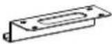
B (x1)
CABLE HOLDER
C (x1)
CLOTH DRAWER CLOTH DRAWER BRACKETS
D (x2)
PACKAGE 2
E (x1) F (x1) G (x1)
LEFT LEG MIDDLE LEG
RIGHT LEG
H (x1)
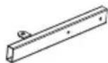
LEFT CROSSBAR
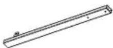
I (x1) J (x1)
MIDDLE CROSSBAR

MIDDLE CROSSBAR
K (x1)
RIGHT CROSSBAR
L (×2)
FEET
M (x2)
SIDE PLATES
N (x1)
SHORT FRAME JOINT

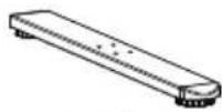
O (x1)
LONG FRAME JOINT

P (x1)
CONTROL PANEL
Q (x1)
POWER ADAPTER
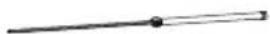
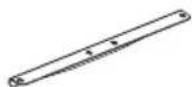
R (x1)
TRANSMISSION ROD

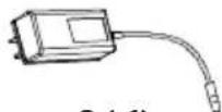
S (x1)
MOTOR CONNECTION CABLE

T (x2)
HEADPHONE HOOKS
HARDWARE CONTENTS

M6x11 BOLT

M5x16 SCREW 2mm
b (x8)a (x20)
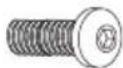
M6x35 BOLT
e (x1)d (x53)
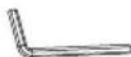
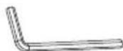
HEX WRENCH

C (x2)
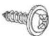
M3.5×19 SCREW
f (x1)
5mm
HEX WRENCH
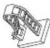
CABLE MANAGEMENT CLIP

h (x23)g (x4)
RUBBER PADS

i (x4)
TABLETOP CONNECTORS DRAWER STOPPERS

j (x2)
EXTRA PARTS

a (x2)
M6x11 BOLT

C (x2)
M3.5x19 SCREW
d (x2)
M5x16 SCREW
h (x2)
RUBBER PADS
Step 1
Assembling the Leg Sections
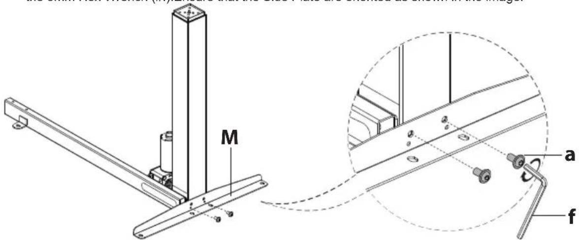
1-1 Assemble the left leg section
On a flat and open section of the floor, position the Left Leg (#E) and Left Crossbar (#H) in the configuration shown here. As shown in magnification bubble, using the Bolts (#a) tighten until secure using the 5mm Hex Wrench (#f).

Attach the Side Plate (#M) to the Left Leg (#E) using Bolts (#a) and tighten until secure using the 5mm Hex Wrench (#f). Ensure that the Side Plate are oriented as shown in the image.
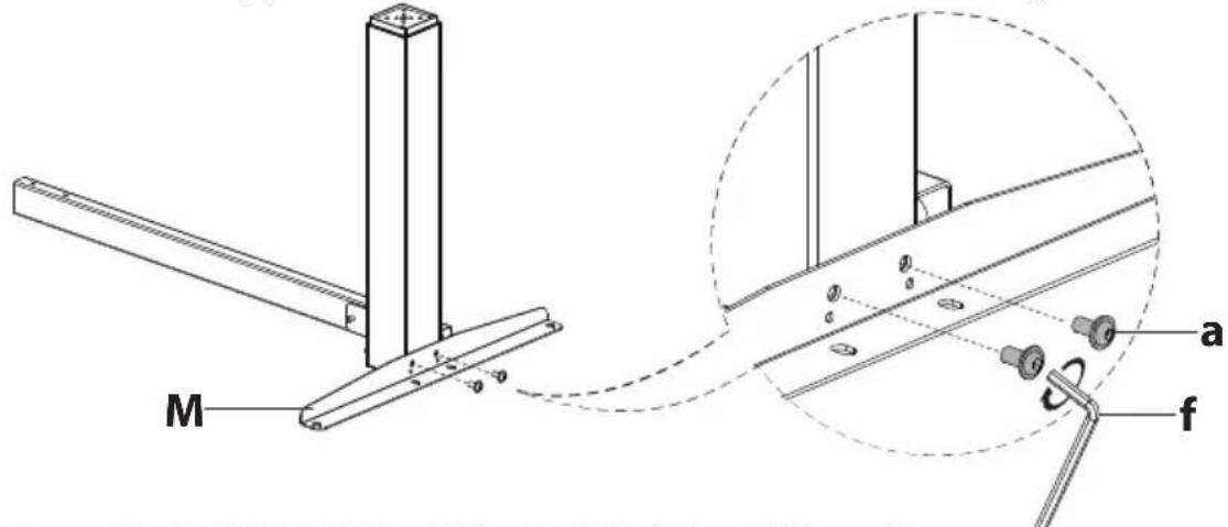
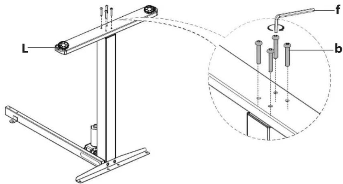
Attach one of the Feet (#L) to the Leg (#E), using Bolts (#b) and tighten until secure using the 5mm Hex Wrench (#f).

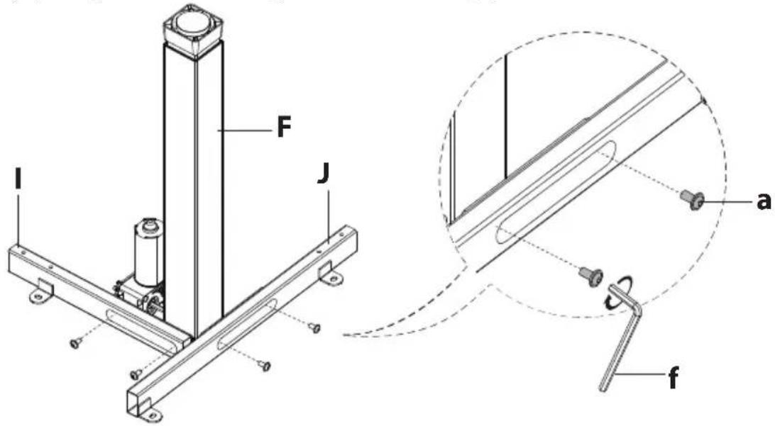
1-2 Assemble the middle leg section
On a flat and open section of the floor, position the Middle Leg (#F) and Middle Crossbars (#I and #J) in the configuration shown here.
As shown in magnification bubble, connect the Leg to the Crossbars using the Bolts (#a) and tighten until secure using the 5mm Hex Wrench (#f).
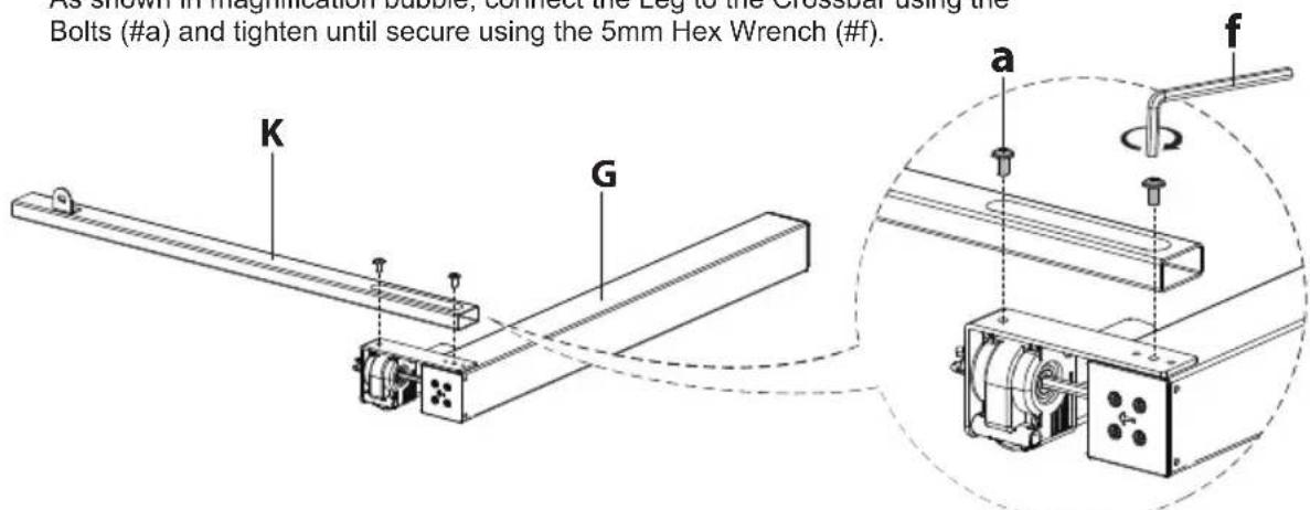
1-3 Assemble the right leg section
position the Right Leg (#G) and Right Crossbars (#K) in the configuration shown here.
As shown in magnification bubble, connect the Leg to the Crossbar using the Bolts (#a) and tighten until secure using the 5mm Hex Wrench (#f).
Attach the Side Plate (#M) to the Right Leg (#G) using Bolts (#a) and tighten until secure using the 5mm Hex Wrench (#f). Ensure that the Side Plate are oriented as shown in the image.
Attach one of the Feet (#L) to the Leg (#G), using Bolts (#b) and tighten until secure using the 5mm Hex Wrench (#f).
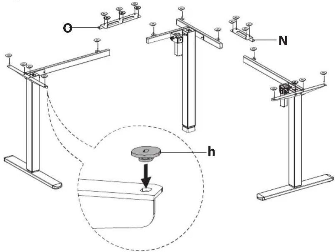
1-4 Attach the Rubber Pad
Turn the desk over so that it is standing on the feet. Attach the Rubber Pads (#h) to the top of the Leg Sections and Frame Joint (#N, O) in the locations shown here. All 23 pads will be used.
Step 2
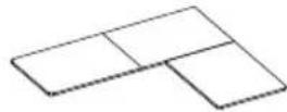
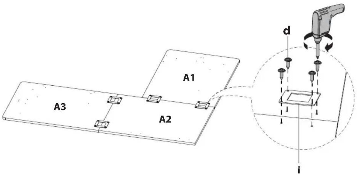
Assemble the Desktop
Lay the Desktop (#A) pieces out upside-down in the configuration shown below. Reference the stickers on the underside to identify the proper pieces so that they connect in order left to right A1, A2, A3. Use the Tabletop Connectors (#i) in the locations shown and secure in place using Screws (#d). Tighten until secure.

Option B: Long side of desk on the left hand side
Step 3
Attaching the Frame to the Desktop
Option A: Long side of desk on the right hand side
Turn the leg frames over and carefully place it upside down on the desktop. Place the Leg Sections on the Desktop, then connect the Leg Sections together, using the Frame Joint (#N, O) and using Bolts (#a) and tighten until secure using the 5mm Hex Wrench (#f).

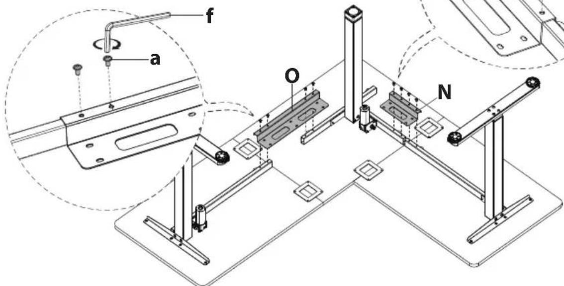
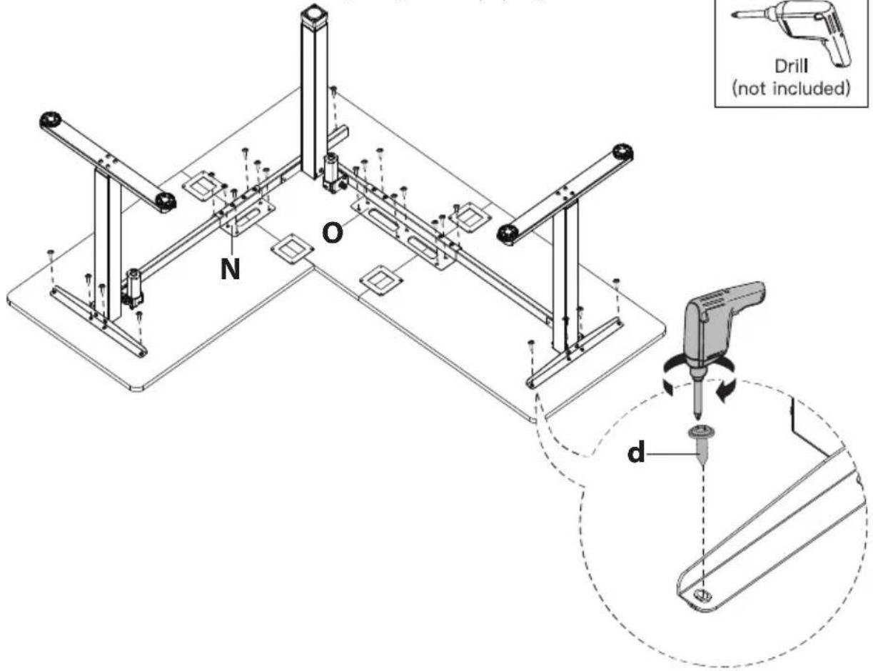
Align the holes on the Frame with the holes on the Desktop.
Attach the Desk Frame to the Desktop using Screws (#d). Tighten until secure.


Option B: Long side of desk on the left hand side
Turn the leg frames over and carefully place it upside down on the desktop. Place the Leg Sections on the Desktop, then connect the Leg Sections together, using the Frame Joint (#N, O) and using Bolts (#a) and tighten until secure using the 5mm Hex Wrench (#f).
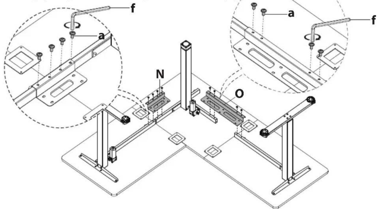
Align the holes on the Frame with the holes on the Desktop. Attach the Desk Frame to the Desktop using Screws (#d). Tighten until secure.
Step 4
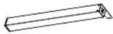
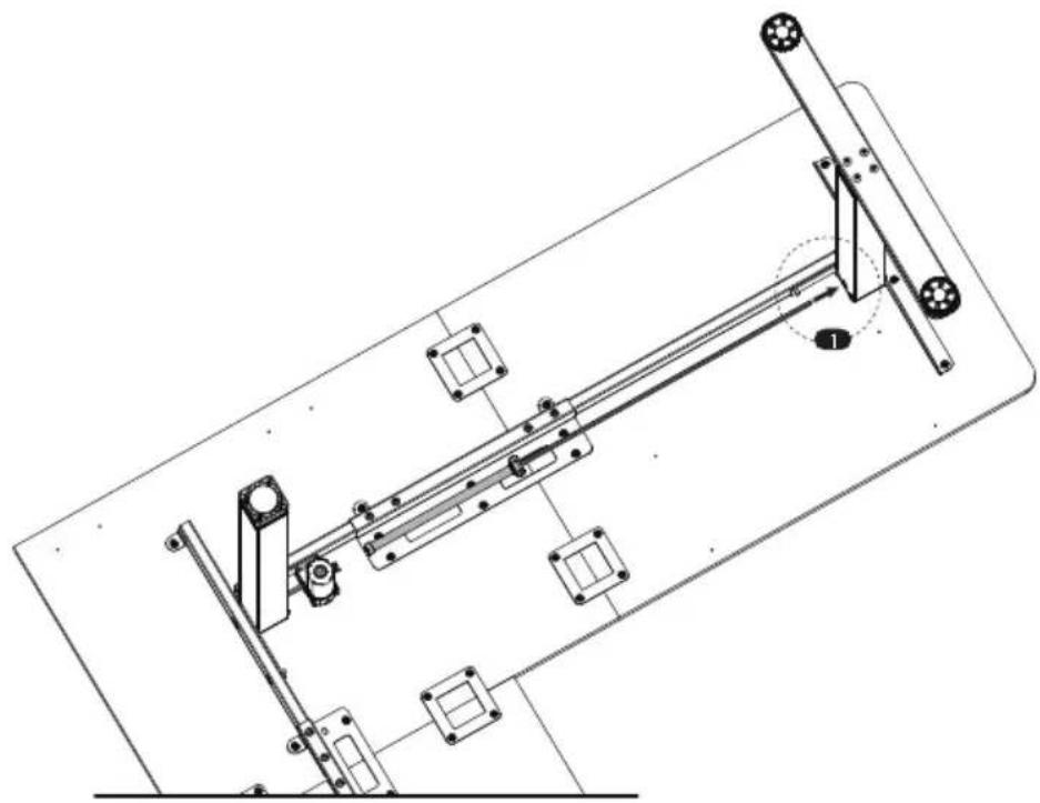
Attaching the Transmission Rod
Setting the Desk Legs to the Same Height
Before attaching the transmission rod, measure the heights of the left and middle desk legs to see if they are set at the same level. If not, insert the transmission rod into the hole in the left leg. Turn the rod to adjust the left leg so it's level with the middle leg. Turn the rod anti-clockwise to lower the left leg or clockwise to raise it.

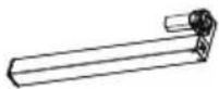
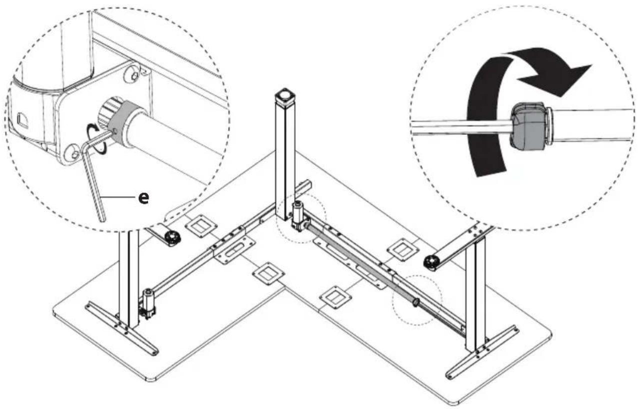
Loosen the coupling nut.
natural_image
Technical line drawing of a mechanical assembly with no visible text or symbols
natural_image
Diagram of a mechanical assembly with a rotating shaft and flange, enclosed in a dashed circle (no text or symbols)
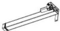
Ensure the transmission rod is properly inserted into the hole in the left leg. Extend the rod to connect the other end to the motor drive shaft on the Middle Desk Leg.
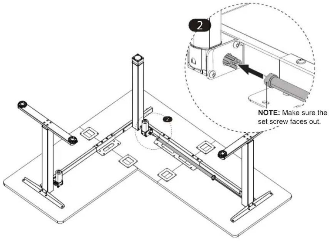
Secure the transmission rod to the motor drive shaft by turning the set screw clockwise. Then tighten the coupling nut to fine-tune transmission rod fit.
Step 5
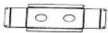
Fold the Cable Holder and Cloth Drawer Brackets
Fold the Cable Holder and Cloth Drawer Brackets into the shape shown in the image. Fold with care, do not fold and unfold. If needed use the edge of a table or other solid edge to assist with folding them.

flowchart
graph TD
    A["Cable Holder"] --> B["Step 1: Cable Holder with two circular holes"]
    B --> C["Step 2: Cable Holder with three circular holes"]
    C --> D["Step 3: Cable Holder with a rectangular block and arrow indicating rotation"]
    D --> E["Final Structure with curved arrows showing rotation"]
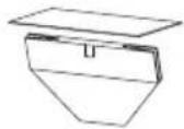
Cloth Drawer Brackets
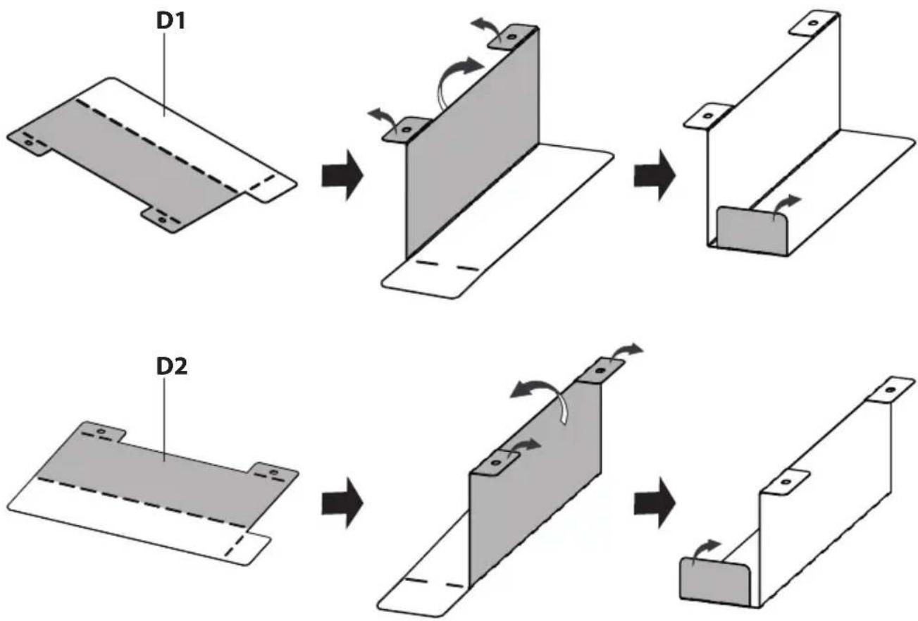
flowchart
graph TD
    A["D1"] --> B["Assembly Step 1"]
    B --> C["Step 2"]
    C --> D["Step 3"]
    D --> E["Step 4"]
    E --> F["Step 5"]
Step 6
Attach the Cable Holder / Headphone Hook / Control Panel and Cloth Drawer Brackets
Attach the Cable Holder (#B) and Headphone Hooks (#T) to the Desktop, using Screws (#d). Attach the Control Panel (#P) to the Desktop, using Screws (#c).

Attach the Cable Holder (#B) and Headphone Hooks (#T) to the Desktop, using Screws (#d). Attach the Control Panel (#P) to the Desktop, using Screws (#c).

Assemble the Cloth Drawer

natural_image
Technical line drawing of a mechanical assembly with two vertical posts and mounting base (no text or symbols)
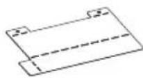
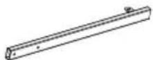
Attach the Drawer Stoppers (#j) in the locations shown using Screws (#d), this will prevent the drawer from being accidentally removed from the desk.
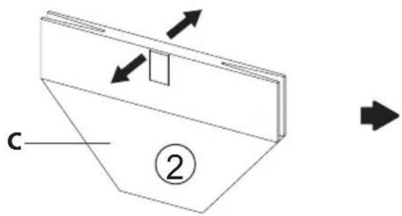

Unfold the Cloth Drawer (#C) and put in the rectangular insert.

natural_image
Technical diagram of a mechanical assembly with two vertical rods and a base, showing alignment and movement direction (no text or symbols)Place the assembled Cloth Drawer (#C) upside down on the desk so that it is covering the Drawer Stoppers (#j) and in between the pre-drilled holes on each side.

Attach the Cloth Drawer Brackets (#D) to the Desktop using Screws (#d) so that they hold the Cloth Drawer in place.
Step 7
Connect the Power Lines and Attach the Cable Clips
Connect the Power Lines
Connect the Power Lines as shown in the image.
Attach the Cable Clips
Attach the Cable Clips (#g) to the underside of the desktop as needed. It is recommended that they be placed approximately in the middle of each length of wire to prevent the cords from hanging too low. Open the Cable Clip as shown in the magnification bubbles, insert the cord and close the clip again.

Step 8
Connect the Power
Flip the desk over and connect the power adapter (#Q) to a wall outlet.
Please follow the reset procedure before operating the desk: Press and hold the down button for 5 seconds, and the screen will show "RES". Continue holding until the desk goes down to its lowest level and comes back up slightly.
Caution: Heavy, this step may require additional assistance to turn the desk over.

Power Input 110V-240V

Speed 20 mm/s

Motion Noise
<55dB

Load Capability
176 lbs / 80 kg
Warnings

natural_image
Prohibition sign showing a table with a weight symbol above and two chairs below, crossed by a diagonal line (no text or labels)
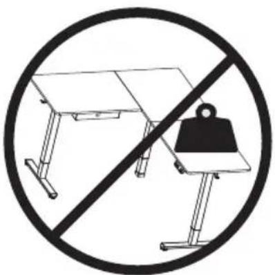
Do not exceed desk weight limit.

natural_image
Diagram of a desktop setup with a laptop and two chairs, crossed out by a diagonal line (no text or symbols)
Keep area of vertical motion free of obstacles.

Keep weight on desk balanced for correct operation and longer life of components.

natural_image
Diagram of a mechanical setup with intersecting planes and arrows, enclosed in a circle (no text or symbols)
Leave enough slack in cables to allow for full range of vertical motion.
Visit us at www.mount-it.com for product registration and warranty information.
Our US based customer service team is standing by to answer any questions you have about your Mount-It! product.
Available by phone Monday - Friday from 8:00am to 4:00pm PST.
Chat live with an agent on our website!

support@mount-it.com

(855) 925-5668

www.mount-it.com


- Extra Large Corner Sit Stand Desk
- Thank you for choosing Mount-It!
- EN
- DE
- PACKAGE CONTENTS
- HARDWARE CONTENTS
- EXTRA PARTS
- Step 1
- Assembling the Leg Sections
- 1-1 Assemble the left leg section
- 1-2 Assemble the middle leg section
- 1-3 Assemble the right leg section
- 1-4 Attach the Rubber Pad
- Step 2
- Assemble the Desktop
- Step 3
- Attaching the Frame to the Desktop
- Option B: Long side of desk on the left hand side
- Step 4
- Attaching the Transmission Rod
- Setting the Desk Legs to the Same Height
- Step 5
- Fold the Cable Holder and Cloth Drawer Brackets
- Step 6
- Attach the Cable Holder / Headphone Hook / Control Panel and Cloth Drawer Brackets
- Assemble the Cloth Drawer
- Step 7
- Connect the Power Lines and Attach the Cable Clips
- Connect the Power Lines
- Attach the Cable Clips
- Step 8
- Connect the Power
- Warnings
Brand : Mount-It!
Model : MI-15010
Category : Office