Yard Master Pro 2 - Projection screen Elite ProAV - Free user manual and instructions
Find the device manual for free Yard Master Pro 2 Elite ProAV in PDF.

| Product Type | Projection Screen |
| Brand | Elite ProAV |
| Model | Yard Master Pro 2 |
| Screen Material | Matte White |
| Aspect Ratio | 16:9 |
| Diagonal Size | 100 inches |
| Viewable Area | 87" x 49" |
| Frame Type | Portable Tripod Stand |
| Weight | 12.5 kg (27.5 lbs) |
| Folded Dimensions | 90" x 6" x 6" |
| Mounting | Floor-standing (Tripod) |
| Color | Black Housing |
| Screen Gain | 1.0 |
| Viewing Angle | 160° |
| Cleaning | Use soft dry cloth; avoid solvents |
| Safety | Stable base required; do not use in strong winds |
| Spare Parts | Screen fabric, frame, carrying case available |
| Repairability | Contact Elite ProAV for replacement parts |
| General Use | Indoor/Outdoor |
Frequently Asked Questions - Yard Master Pro 2 Elite ProAV
User questions about Yard Master Pro 2 Elite ProAV
0 question about this device. Answer the ones you know or ask your own.
Ask a new question about this device
Download the instructions for your Projection screen in PDF format for free! Find your manual Yard Master Pro 2 - Elite ProAV and take your electronic device back in hand. On this page are published all the documents necessary for the use of your device. Yard Master Pro 2 by Elite ProAV.
USER MANUAL Yard Master Pro 2 Elite ProAV
text_image
ELITE PROAVYard Master Pro 2 Series
Indoor/Outdoor Folding-Frame Portable Projection Screen User's Guide
Thank you for choosing the Yard Master Pro 2 portable projection screen! Please read this user guide before utilizing the screen. Correct usage and maintenance will ensure a long product life
Care & Use Instructions
◆ Elite highly recommends two people to assemble the Yard Master Pro 2 screen.
◆Dust, dirt and scratches on the projection surface will affect the picture quality, please take note of the points below to prevent that from occurring:
- Do not touch the projection surface with your hands
- Do not write or draw on the projection surface
- Do not use fingers or sharp objects to point on the projection surface; this will damage the screen material.
- Use a soft-damp cloth to clean the projection surface; do not use chemical cleaning agents or alcohol.
- Use clean water when dampening the cleaning cloth and do not rub against the material to clean it.
◆ After using the screen, disassemble it and store it in the carrying bag provided.
◆To avoid damage and injury, the screen should only be operated by adults.
Product Description
Design: The aluminum frame is designed to be light weight and easily operated making it easy to carry, assemble and disassemble.
Projection Screen Surfaces: The screen surface is attached to the rectangular frame and held in place by snap buttons, which ensure an evenly stretched and flat surface. The screen materials are durable and can be folded many times without causing damage or distortion to the surfaces.
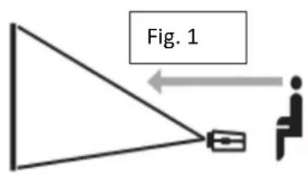
Correct usage of the projection screen will ensure better viewing results.
For front projection (CineWhite®), assemble and view the screen as indicated in Fig.1.
For rear projection (WraithVeil), assemble and view the screen as indicated in Fig. 2.
text_image
Fig. 1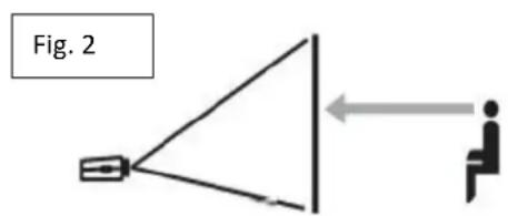
text_image
Fig. 2Hardware and Parts List
A. Folding frame x1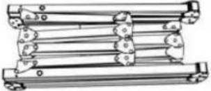 | B. Left and right folding legs x2 | C. Knob Screw (Refer to Chart)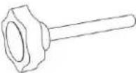 |
D. Front Projection screen material x1 | E. Screen material bag x1 | F. Carrying Bag x1 |
G. Rope x2 | H. Eyebolt x2 | I. Stake x4 |
Note: The parts list above is subject to change without notice.
| Models | Knob Screw | Max Height |
| 145” (16:9) | 10 pcs | 133.5 inches |
| 180” (16:9) | 10 pcs | 159.8 inches |
| 200” (16:9) | 14 pcs | 149.6 inches |
Frame Assembly
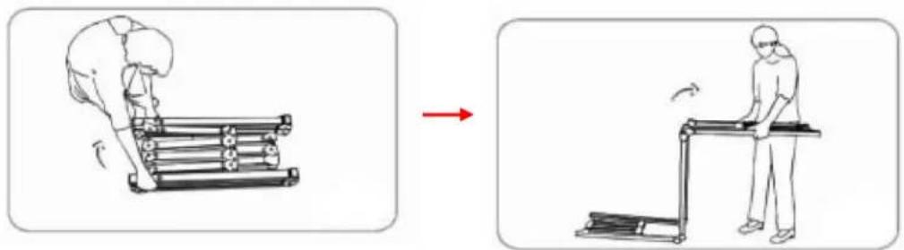
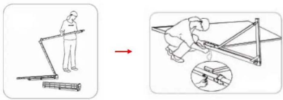
- Take the folding frame (A) out of the carrying bag (F) and place it on a flat surface. Fully unfold the longer sections first, as shown below.
natural_image
Illustration showing a person using a treadmill to lift a roller, with a red arrow indicating motion (no text or symbols)- Next, unfold the frame until the latch on the hinge "clicks" into place. Repeat the procedure for the shorter sections, as shown below.

text_image
"click"Note: When unfolding the frame and legs, be sure the latches on the hinges "click" into place. Please also make sure all 4 corners of the frame are at a 90^ angle and the hinged support bar is straight and not bent.

text_image
Diagram illustrating a structural change with hand positioning and a 3D frame structure, showing directional arrows.Screen Material Attachment
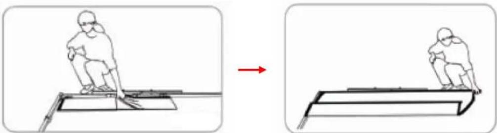
- Take the screen material (D) out of the screen material bag (E) and align the corners of the screen material with the inside corners of the frame.
natural_image
Two-step diagram showing a person climbing a ramp, with a red arrow indicating motion (no text or symbols)- Once the screen material is fully extended, secure the material by snapping the buttons onto the frame studs. Fasten the buttons in the following order as shown on Fig.1.
Note: Snap the buttons on each corner first, then work your way out to the center on each side.
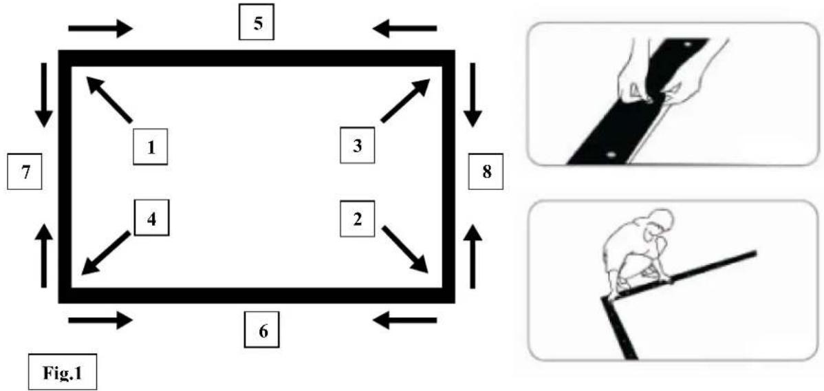
flowchart
graph TD
    A["1"] --> B["2"]
    C["3"] --> D["4"]
    E["5"] --> F["6"]
    G["7"] --> H["8"]
    I["Fig.1"] --> J["6"]
    style A fill:#f9f,stroke:#333
    style C fill:#f9f,stroke:#333
    style E fill:#f9f,stroke:#333
    style G fill:#f9f,stroke:#333
    style I fill:#f9f,stroke:#333
    style J fill:#f9f,stroke:#333
Leg Attachment
- Carefully take the left and right folding legs (B) out of the carrying bag (F) and place it on a flat surface. Unfold the left and right legs leaving the front foot folded as shown below. Make sure the hinges click into place.
Warning: The additional support sections, located at the middle section of the legs, may unfold on its own. Please be sure to use caution while removing/placing the legs from/to the bag
- Once the legs are unfolded, lay the frame on the floor and position the legs over both sides of the frame. Use the knob screws (C) to attach the frame to the legs.
Warning: When attaching the legs, make sure to screw the top of the leg to the last hole of the frame to reach max height. Attaching the legs lower to the frame and leaving an extra space on top may cause the screen to tip over when assembled.
text_image
Diagram illustrating a person using a ladder to lift a cart, with a magnified inset showing the step and detail of the motion.- After making sure the legs are secure to the frame, using two people, lift the screen up in a vertical position. While the screen is in a vertical position, fold the front feet of the legs out.

natural_image
Two figures assembling a large frame with tape measure, no text or symbols present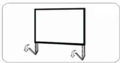
natural_image
Simple line drawing of a blank board with two legs and arrows indicating direction (no text or symbols)
natural_image
Simple line drawing of a rectangular frame mounted on two supports (no text or symbols)- The assembly is now complete and the projection screen will be stable on a flat surface.
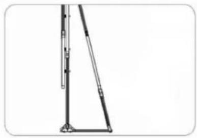
Leg Attachment for 135" – 200" Models
- Starting from step 2 on the previous procedure, lay the frame on the floor and position the legs over both sides of the frame. Use the knob screws (C) to attach the frame to the legs.
Warning: When attaching the legs, make sure to screw the top of the leg to the last hole of the frame to reach max height. Attaching the legs lower to the frame and leaving an extra space on top may cause the screen to tip over when assembled.
- Next, carefully unfold the extra support leg behind the leg and attach it securely using a knob screw (C). Then repeat steps 3 and 4 on the previous procedure.
natural_image
Pure mechanical linkage diagram without any text, numbers, or symbols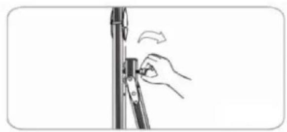
natural_image
Hand adjusting a vertical mechanical component with an arrow indicating rotation (no text or symbols)Screen Disassembly
- After using the screen, disassemble and store it in the carrying bag (F). To disassemble the screen, follow the assembly procedure in reverse order.
- Store the screen in the provided carrying bag (F). Be sure to place folding frame, legs, and smaller parts into the carrying bag first and place the material on top to keep material from creasing or tearing.
For more information, technical support or your local Elite Screens contact, please visit www.eliteproav.com