Airflo Spa - Spa Waterco - Free user manual and instructions
Find the device manual for free Airflo Spa Waterco in PDF.

User questions about Airflo Spa Waterco
0 question about this device. Answer the ones you know or ask your own.
Ask a new question about this device
Download the instructions for your Spa in PDF format for free! Find your manual Airflo Spa - Waterco and take your electronic device back in hand. On this page are published all the documents necessary for the use of your device. Airflo Spa by Waterco.
USER MANUAL Airflo Spa Waterco
WARNING
This equipment must be installed and serviced by a qualified technician. Improper installation can create electrical hazards which could result in property damage, serious injury or death. Improper installation will void the warranty.

Notice to Installer
This manual contains important information about the installation, operation and safe use of this product. Once the product has been installed this manual must be given to the owner/ operator of this equipment.
IMPORTANT SAFETY INSTRUCTIONS
When installing and using this electrical equipment, basic safety precautions should always be followed, including the following:
READ AND FOLLOW ALL INSTRUCTIONS
WARNING
To reduce the risk of injury, do not permit children or infirm persons to use this product unless they are closely supervised at all times.
WARNING
RISK OF ELECTRIC SHOCK
Connect only to a grounding type receptacle protected by a ground-fault circuit-interrupter (GFCI) or a Residual Current Device (RCD) with a rated residual current not exceeding 30mA. Contact a qualified electrician if you cannot verify that the receptacle is protected by a GFCI or an RCD.
WARNING
To reduce the risk of Electric Shock, if the electrical power supply cord is damaged it must be replaced immediately by the manufacturer, service agent or similarly qualified person in order to avoid hazard.
The power supply cord should be located and protected to prevent the cord from sustaining damage from lawn mowers, hedge trimmers and other equipment. Do not bury cord.
Do not run this product on an extension cord. Damage to the electrical components may result.
Install in a well ventilated area. Do not bundle excess power supply cord near items that generate heat. Property damage, serious injury or death may result.
Any modification of this product requires the prior consent of the manufacturer. Original replacement parts and accessories authorised by the manufacturer ensure a high level of safety. The manufacturer accepts no liability for the damage and injuries caused by unauthorised replacement parts and accessories.
CAUTION
RISK OF ELECTRIC SHOCK
Installation or repairs should be carried out by the manufacturer, service agent or a similarly qualified person in order to avoid hazards.
Work may only be performed on this product after disconnecting it from the mains power.
SAVE THESE INSTRUCTIONS
Table of Contents
WATERCO SPA BLOWERS
MODELS
Standard Model - Airflo, Whisperair, Whisperair S ---- 01
Inline Model - Whisperair Elite, Whisperair S Elite ---- 01
INSTALLATION
Mounting 02
Switching the Outlet Port 02
Above Water Level Installation 02
Below Water Level Installation 02
Piping 03
To Connect Piping to the Blower 04
Spa Jet Booster Installation 04
(Additional Requirements)
Air Manifold Installation 04
(Additional Requirements)
Airswitch Models 06
(Whisperair S and Whisperair S Elite)
OPERATION
Basic Models 06
(Airflo and Whisperair)
Airswitch Models 06
(Whisperair S and Whisperair S Elite)
TROUBLESHOOTING
Troubleshooting 07
WATERCO SPA BLOWER
The following instructions cover all models of Waterco Spa Pool Blowers (Airflo and the Whisperair line). While much of this manual applies to all blowers, please identify your model and follow any specific instructions that relate to it.
Waterco Blowers are designed for use in either Spa Jet Booster or Air Manifold applications where, in both cases, air is forced through the connecting piping and into the Spa. They are suitable for both above and below water level installations provided the guidelines set out in this manual are followed.
Waterco Blowers have an integrated Thermal Cutout that will switch off the electric motor if it overheats. If the Thermal Cutout is tripped, the motor will automatically restart once it has sufficiently cooled down.
Waterco Blowers are designed to meet the specifications set out in AS/NZS 3136.
MODELS
Standard Model - Airflo, Whisperair, Whisperair S
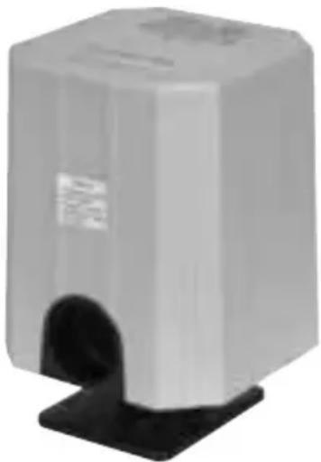
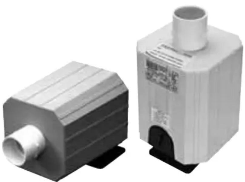
The standard model of the Blower draws air into the unit through the Bottom Cowl of the Blower.
The Airflo version has plainly visible Air Inlet holes throughout the Bottom Cowl, while the Whisperair models draw all the required air in through gaps around the perimeter of the Bottom Cowl.
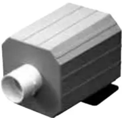
Inline Model – Whisperair Elite, Whisperair S Elite
The Inline version of the Blower differs from the Standard Model in that rather than having Air Inlet holes in the Bottom Cowl of the casing, it has an Inlet Port in the top of the Outer Housing. The piping connected to this port should then be extended to a safe and convenient position. This makes the Inline Model quieter than the Standard Model when running.
natural_image
Exterior view of a gray rectangular electronic device with a black base (no visible text or symbols)Figure 1-1: Standard Model
natural_image
3D rendered mechanical component with ribbed top and central shaft (no text or symbols)Figure 1-2: Inline Model
INSTALLATION
WARNING
INSTALL IN A WELL VENTILATED AREA FREE FROM FLOODING AND ENSURE AREA IS FREE FROM SPLASHING WATER.
Mounting
All models of Waterco Blower have two (2) identical 50 mm (2") diameter Outlet Ports. One of the ports is in the Bottom Cowl of the Blower and the other is in the side of the Blower. The Stand can be attached to either of these ports and leaves the other free to connect to the Spa via the piping. It is also possible to connect the pipe to the Outlet Port in the Bottom Cowl of the Blower and seal off the other Outlet Port. In this case, the piping must be adequately supported to carry the weight of the Blower. Waterco supplies a 50mm (2") Cap (P/N S130571) for this purpose with all Whisperair Blowers (sold separately for Airflo).
It is recommended that the Inline Models be mounted with the Air Inlet Port facing upwards. This will reduce the number of elbows required for the piping. Examples of mounting the Blower are shown below.
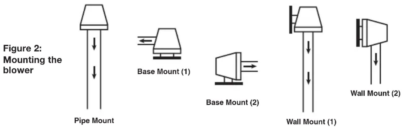
* Arrows indicate direction of airflow
Switching the Outlet Port
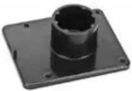
The blower is packaged with the Mounting Bracket in the base of the Blower and the Outlet Port in the side. Assuming there is no piping connected to the Blower, simply follow these steps to switch the Mounting Bracket from one port to the other.
- The Mounting Bracket is held in place by a small securing screw on the flange of the port. Remove this screw.
- Pull the Mounting Bracket out of the port (it is a press fit). A fair amount of force will be required to remove the Mounting Bracket. If it is stuck, use a soft hammer to tap the side of the bracket until it rotates a little. If it still won't come out, tap the Mounting Bracket from the Blower side, alternating between corners on the Mounting Bracket. The Mounting Bracket is quite strong, but care should still be taken not to damage it or the Blower.
- Remove the securing screw from the other port and insert the Mounting Bracket.
- Replace both securing screws.
natural_image
Black plastic mechanical component with a hexagonal bolted shaft and flange base (no text or symbols visible)Figure 3: Mounting Bracket
natural_image
Two industrial pipe fittings, one cylindrical and one rectangular, shown against a white background (no text or symbols visible)Figure 4: Inline Model blowers showing possible locations of Mounting Brackets
Piping
When arranging the piping connections to the Blower, observe the following,
- 50 mm (2") Class 9 or higher PVC pipe should be used in the installation. Using smaller diameter pipe will place stress on the motor.
- Do not glue piping to the Blower.
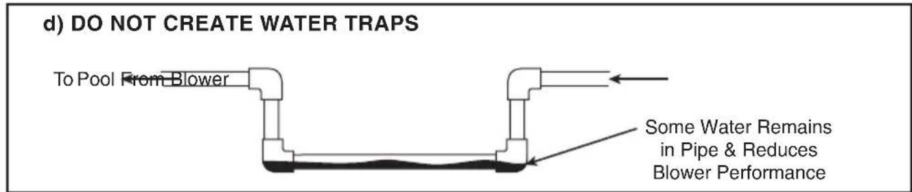
- Avoid water traps when installing the piping as they will reduce the efficiency of the Blower (refer to Figure 5d on Page 8).
- Install pipe loops where necessary (refer to Figure 5c on Page 6).
- Horizontal pipes shall have a one (1) degree fall towards the Spa.
- Check Valves shall be installed when the Blower is used in a Spa Jet Installation (refer to Figure 5a on Page 6).
- Keep the number of 90 degree elbows to a minimum. Where possible, use two (2) 45 degree elbows instead of a 90 degree elbow.
- Keep the length of piping between the Spa and the Blower as short as possible (length of piping should not exceed 12 metres).
CAUTION
Care must be taken to ensure loose material or water (including rain) will not be sucked into the piping connected to the Inlet Port of the Inline Blower. Failure to do so may result in serious damage.
To Connect Piping to the Blower
- Unscrew the small securing screw from the Outlet Port.
- Smear some silicon sealant around the inside surface of the Outlet Port.
- Insert the pipe into the Outlet Port and tighten the securing screw.
Above Water Level Installation
(Refer to Figure 5 a & b on Page 5)
The bottom of the Blower should be at least 700mm above the water level of the spa to prevent water from entering the blower.
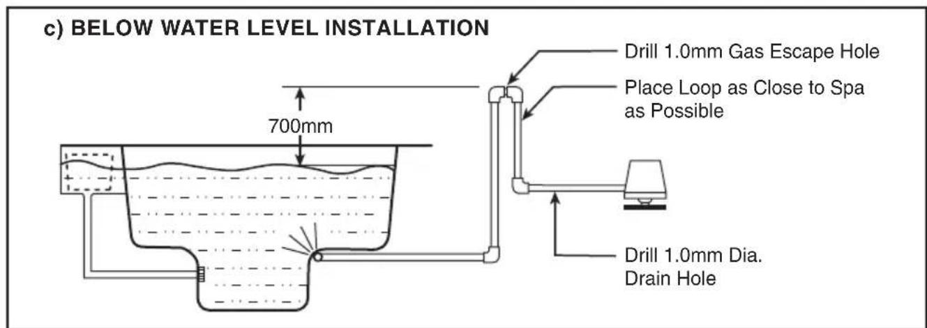
Below Water Level Installation
(Refer to Figure 5c on Page 5)
The connecting piping must have a vertical loop where the top of the loop is at least 700mm above the water level of the Spa. The loop should be as close to the Spa as possible and must have a 1.0mm hole in the top of the loop to allow gas to escape. A 1.0mm hole is also required as a drain hole to prevent any water from entering the Blower.
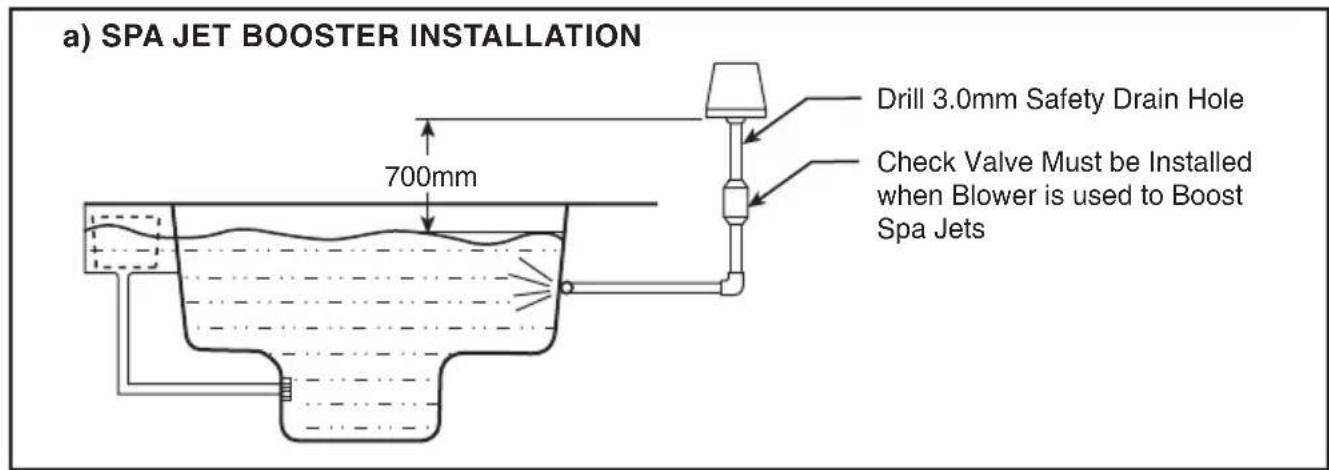
Spa Jet Booster Installation (Additional Requirements)
(Refer to Figure 5a on Page 5)
If using the Blower in a Spa Jet Booster application, take the following steps,
Install a Check Valve in-line with the Blower. This is a one-way valve that will ensure no water enters the Blower.
Ensure there is a 3.0mm drain hole between the Check Valve and the Blower.
For maximum efficiency of the Blower, keep the number of jets between 6 and 8.
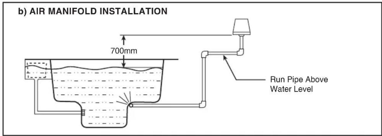
Air Manifold Installation (Additional Requirements)
(Refer to Figure 5b on Page 5)
This style of installation requires a suitable number of holes to be present in the seat of the spa for the blower to work efficiently.
Minimum number of holes with 6mm diameter : 36
Minimum number of holes with 9mm diameter : 18
Figure 5: Installation Tips
Airswitch Models (Whisperair S and Whisperair S Elite)
The Whisperair S and Whisperair S Elite come with an Airswitch Controller and connecting tubing to provide remote activation / deactivation of the Blower. The Button for the Airswitch Controller is designed to be installed in the shell of the Spa and is connected to the Blower via the tubing. A Waterco supplied Airswitch Button and connecting tubing must be used with these models of Blower to ensure trouble free operation.
For easy installation / removal of the remote button for the Airswitch, make sure there is sufficient free length of tubing to pull through the shell of the Spa and connect to the button. Once installed, the join between the Button Flange and the Spa shell should be sealed with a silicone sealant.
NOTE: The air tubing should never be exposed to direct sunlight and should preferably be buried alongside the pool piping where possible. Avoid crushing or kinking the hose.
To remove the remote button, from the shell of the spa, simply slide a sharp thin knife under the Button Flange to cut the silicone bead and then lift out.
OPERATION
Operation will greatly depend on the electrical connection between the Blower and the other spa equipment. If you are using a single controller to operate all your spa equipment, refer to the operating instructions of the controller.
Airflo and Whisperair
Simply plug the power cable into a power point and switch it on.
Airswitch Models (Whisperair S and Whisperair S Elite)
To operate those Blowers with an Airswitch, simply press the remote button to switch the Blower on / off.
TROUBLESHOOTING GUIDE
The Blower should only be serviced by a registered electrician or a serviceperson. However, if a fault is suspected, there are several things that the owner can check before the serviceperson is called in.
| SYMPTOMS PROBABLE CAUSE ACTION | ||
| BLOWER PERFORMS POORLY | Airflow is restricted. Check for blockages in the Blower, piping or in the nozzles / holes in the Spa. | |
| Motor or Impeller damaged. Replace and see above. | ||
| BLOWER STOPS WITHOUT WARNING | Thermal Overload tripped due to low air flow through the motor. | Check for blockages in the Blower, piping or in the nozzles / holes in the Spa. |
| Ensure pipe-work, number of holes in the Spa, and Blower height above the water conform with that specified in Installation (refer to Page 3). | ||
| Motor brushes are worn out. Replace motor brushes. Life of brushes is approximately 500 hours. | ||
| Water has entered the motor and caused a short circuit. | Replace and ensure Blower is 700mm above water level or fitted with loop. A Blower used to boost Spa Jets must be fitted with a Check Valve. Refer to Installation on Page 4. | |
| BLOWER FAILS TO START | No power. Ensure power is switched on. | |
| Motor burnt out. Check water has not entered the Blower and burnt out the motor. | ||
| Incompatible air button and tube (Airswitch models only). | Ensure button and tube supplied with Airswitch are being used. Other air buttons may not have sufficient air capacity. | |
| Blower is actually stopping as soon as it starts. | Refer to “Blower Stops Without Warning”. | |
WARNING
If the Waterco Limited Product is within the stated warranty period and you experience faults always contact your supplier or the nearest Waterco Limited branch for advice. Failure to do this may void the warranty. Refer to Warranty Terms and Conditions supplied with the product.
All electrical work is to be carried out by an Authorised Electrician. Under no circumstances should you attempt repairs on the electrical components of Waterco Limited products unless you are qualified to do so.
OFFICES - AUSTRALIA
NSW - SYDNEY
(HEAD OFFICE)
Tel: +61 2 9898 8600
QLD - BRISBANE
Tel: +61 7 3299 9900
VIC/TAS - MELBOURNE
Tel: +61 3 9764 1211
WA - PERTH
Tel: +61 8 9273 1900
SA/NT - ADELAIDE
Tel: +61 8 8244 6000
ACT DISTRIBUTION
Tel: +61 2 6280 6476
OFFICES - OVERSEAS
WATERCO (EUROPE) LIMITED
Sittingbourne, Kent, UK
Tel: +44 (0) 1795 521 733
WATERCO FRANCE
Saint Priest, France
Tel: +33 4 72 79 33 30
WATERCO (USA) INC
Augusta, Georgia, USA
Tel: +1 706 793 7291
WATERCO CANADA
Longueuil, Quebec, Canada
Tel: +1 450 748 1421
WATERCO (NZ) LIMITED
Auckland, New Zealand
Tel: +64 9 525 7570
WATERCO © LIMITED
Guangzhou, China
Tel: +86 20 3222 2180
WATERCO (FAR EAST) SDN BHD
Selangor, Malaysia
Tel: +60 3 6145 6000
PT WATERCO INDONESIA
Jakarta, Indonesia
Tel: +62 21 4585 1481
WATERCO SINGAPORE INTL PTE LTD
Nehsons Building, Singapore
Tel: +65 6344 2378