PAP-5032 - Intercom RTS - Free user manual and instructions
Find the device manual for free PAP-5032 RTS in PDF.

| Product Type | Intercom |
| Brand | RTS |
| Model | PAP-5032 |
| Dimensions (HxWxD) | 180 x 120 x 30 mm |
| Weight | 0.3 kg |
| Power Supply | 12V DC, 500 mA |
| Operating Temperature | -10°C to 50°C |
| Audio Type | Full-duplex, hands-free |
| Door Release Function | Yes, electric strike compatible |
| Number of Stations | Up to 4 units |
| Mounting Type | Wall-mount, flush or surface |
| Material | ABS plastic |
| Waterproof Rating | IP54 (outdoor unit) |
| Wiring | 2-wire bus, polarity insensitive |
| Included Accessories | Mounting bracket, screws, manual |
| Maintenance | Wipe with dry cloth; avoid solvents |
| Security | Privacy mode, anti-tamper screws |
| Spare Parts Availability | Replacement handsets, door release modules |
| Warranty | 2 years |
Frequently Asked Questions - PAP-5032 RTS
User questions about PAP-5032 RTS
0 question about this device. Answer the ones you know or ask your own.
Ask a new question about this device
Download the instructions for your Intercom in PDF format for free! Find your manual PAP-5032 - RTS and take your electronic device back in hand. On this page are published all the documents necessary for the use of your device. PAP-5032 by RTS.
USER MANUAL PAP-5032 RTS
Program Assignment Panel Technical Manual
up to and including version 1.0.0

PROPRIETARY NOTICE
The product information and design disclosed herein were originated by and are the property of Bosch Security Systems, Inc. Bosch reserves all patent, proprietary design, manufacturing, reproduction, use and sales rights thereto, and to any article disclosed therein, except to the extent rights are expressly granted to others.
COPYRIGHT NOTICE
Copyright 2019 by Bosch Security Systems, Inc. All rights reserved. Reproduction, in whole or in part, without prior written permission from Bosch is prohibited.
*All other trademarks are property of their respective owners.
WARRANTY AND SERVICE INFORMATION
For warranty and service information, refer to the appropriate web site below:
RTS Intercoms ...... www.rtsintercoms.com
RTS Digital
RTSTW
AudioCom
RadioCom
Intercom Headsets
CUSTOMER SUPPORT
Technical questions should be directed to:
Customer Service Department
Bosch Security Systems, Inc.
www.rtsintercoms.com
TECHNICAL QUESTIONS
Bosch Security Systems Technical Support
http://www.rtsintercoms.com/support
DISCLAIMER
The manufacturer of the equipment described herein makes no expressed or implied warranty with respect to anything contained in this manual and shall not be held liable for any implied warranties of fitness for a particular application or for any indirect, special, or consequential damages. The information contained herein is subject to change without prior notice and shall not be construed as an expressed or implied commitment on the part of the manufacturer.
|  THE LIGHTNING FLASH AND ARROWHEAD WITHIN THE TRIANGLE IS A WARNING SIGN ALERTING YOU OF "DANGEROUS VOLTAGE" INSIDE THE PRODUCT. | CAUTION RISK OF ELECTRIC SHOCK DO NOT OPEN CAUTION: TO REDUCE THE RISK OF ELECTRIC SHOCK, DO NOT REMOVE COVER. NO USER-SERVICEABLE PARTS INSIDE. REFER SERVICING TO QUALIFIED SERVICE PERSONNEL. |  THE EXCLAMATION POINT WITHIN THE TRIANGLE IS A WARNING SIGN ALERTING YOU OF IMPORTANT INSTRUCTIONS ACCOMPANYING THE PRODUCT. |
| SEE MARKING ON BOTTOM/BACK OF PRODUCT. | ||
WARNING: APPARATUS SHALL NOT BE EXPOSED TO DRIPPING OR SPLASHING AND NO OBJECTS FILLED WITH LIQUIDS, SUCH AS VASES, SHALL BE PLACED ON THE APPARATUS.
WARNING: THE MAIN POWER PLUG MUST REMAIN READILY OPER-ABLE.
CAUTION: TO REDUCE THE RISK OF ELECTRIC SHOCK, GROUNDING OF THE CENTER PIN OF THIS PLUG MUST BE MAINTAINED.
WARNING: TO REDUCE THE RISK OF FIRE OR ELECTRIC SHOCK, DO NOT EXPOSE THIS APPARATUS TO RAIN OR MOISTURE.
WARNING: TO PREVENT INJURY, THIS APPARATUS MUST BE SECURELY ATTACHED TO THE FLOOR/WALL/RACK IN ACCORDANCE WITH THE INSTALLATION INSTRUCTIONS.
| ~ | This product is AC only. |
| CE |
WARNING: THIS IS A CLASS A PRODUCT. IN A DOMESTIC ENVIRONMENT THIS PRODUCT MAY CAUSE RADIO INTERFERENCE, IN WHICH CASE THE USER MAY BE REQUIRED TO TAKE ADEQUATE MEASURES.
Important Safety Instructions
- Read these instructions.
- Keep these instructions.
- Heed all warnings.
- Follow all instructions.
- Do not use this apparatus near water.
-
Clean only with dry cloth.
-
Do not block any ventilation openings. Install in accordance with the manufacturer's instructions.
-
Do not install near any heat sources such as radiators, heat registers, stoves, or other apparatus (including amplifiers) that produce heat.
-
Do not defeat the safety purpose of the polarized or grounding-type plug. A polarized plug has two blades with one wider than the other. A grounding type plug has two blades and a third grounding prong. The wide blade or the third prong are provided for your safety. If the provided plug does not fit into your outlet, consult an electrician for replacement of the obsolete outlet.
-
Protect the power cord from being walked on or pinched particularly at plugs, convenience receptacles, and the point where they exit from the apparatus.
-
Only use attachments/accessories specified by the manufacturer.
-
Use only with the cart, stand, tripod, bracket, or table specified by the manufacturer, or sold with the apparatus. When a cart is used, use caution when moving the cart/apparatus combination to avoid injury from tip-over.
-
Unplug this apparatus during lightning storms or when unused for long periods of time.
-
Refer all servicing to qualified service personnel. Servicing is required when the apparatus has been damaged in any way, such as power-supply cord or plug is damaged, liquid has been spilled or objects have fallen into the apparatus, the apparatus has been exposed to rain or moisture, does not operate normally, or has been dropped.
Table
of
Contents
INTRODUCTION 9
Features 9
Specifications 10
Reference view - PAP-5032 12
Connector pinouts ....13
INSTALLATION 15
Requirements 15
PAP-5032 installation ....16
Power Up 30
Connections 30
BASIC OPERATION 37
Intercom Keys and Displays ....37
Keypad Reference View ....39
INFO button 43
Breadcrumb Menu Navigation ....44
Menu Navigation and Shaft Encoder Knobs 44
CLR Button 44
Basic Key Operation 45
Panel Volume Adjustments 48
Aux Volume Adjustments 50
Setup Pages 51
User Programmable Buttons 52
Panel Color Window 54
FIRMWARE DOWNLOAD 61
Download Firmware to the Panel From AZedit 61
Download Firmware to the Panel Using the Firmware Upload Tool 64
Enable Downloading New Bootloader from the Panel 65
Download Firmware Using the Bootloader 65
Display the FPGA Version on the Panel 67
Download and Upgrade the FPGA to the PAP-5032 67
Download a Splash Screen 71
Download a Font File 73
Download an Icon File ....75
MENU SYSTEM 77
Main Menu Access 77
6 PAP-5032
Menu System, Audio Options ....78
Menu System, Display 89
Menu System, Key Assign Menu 90
Menu System, Key Options Menu 91
Menu System, OMNEO Offers 94
Menu System, RVON Offers 95
Menu System, Save Config 95
Menu System, Service 96
KEYPAD QUICK REFERENCE 109
Keypad Sequence Introduction ....109
PANEL MENU QUICK REFERENCE 113
Audio Options 113
Display Menu 116
Key Assign Menu 116
Key Options Menu 117
OMNEO Offers Menu 118
Save Config Menu 118
Service Menu 119
EKP-4016PB 121
Introduction ...... 121
Specifications 121
EKP-4016PB Expansion Panel Reference View 122
Expansion Panel Cabling Reference 123
Unicode Support 125
AZedit and Unicode Support 125
Power Supply Mounting Options 129
Power Supply Mounting Bracket Instructions 129
List
of
Figures
FIGURE 1. PAP-5032 Reference View ......12
FIGURE 2. Rear Panel Connections ......16
FIGURE 3. PAP-5032 Connection Warning Message ....18
FIGURE 4. PAP-5032 Connection Warning Message ....30
FIGURE 5. Female Headset Connector Set Screw Access Hole ....31
FIGURE 6. Male Headset Connector Set Screw Access Hole ....31
FIGURE 7. PAP-5032 Keypad ....39
FIGURE 8. Breadcrumbs Navigation ....44
FIGURE 9. Pushbutton Key Function Explanation ....45
FIGURE 10. Listen Indicator ....47
FIGURE 11. Keypanel Colors Window ....54
FIGURE 12. Color Grid ....56
FIGURE 13. Key Assignments Page ....57
FIGURE 14. Miscellaneous Colors Page ....59
FIGURE 15. EKP-4016PB Expansion Panel Reference View – Front and Rear ......122
FIGURE 16. Expansion Panel Cabling ......123
FIGURE 17. Mounting Bracket – Horizontal on a Crossbar ......133
FIGURE 18. Mounting Bracket – Vertical from a Crossbar .....133
This manual describes the installation, programming, and operating procedures for the RTS Model PAP-5032 Program Assign Panel. The PAP-5032 provides the ability to assign one of up to 16 program sources to up to 16 different IFB destinations. The PAP-5032 can be extended up to 64 program sources and 64 IFB destinations via standard EKP expansion panels. The PAP-5032 works with ADAM, ADAM-M and ODIN intercom systems.
Features
• Real-time routing of program audio to IFB outputs
• Audio monitoring of program inputs or IFB outputs
• Real-time gain adjustment of program input and IFB output levels
• Support for analog, OMNEO, or RVON connections to a normal intercom port
NOTE: RVON support requires downloading alternate firmware to the PAP-5032 panel.
Specifications
LCD Display
Active Area ....120.10 mm (wide) x 35.86 mm (high)
Dot Resolution 576 x 172 pixels
Color Resolution ....16-bit (64 K) RGB color
View Angle....80 degrees (typical; all directions)
Power Supply:
Type: External DC
AC Input: 100–240 VAC 50/60 Hz
General Purpose Inputs and Outputs:
Outputs
Type (relays) SPDT
Contact Rating.... 1 AMP @ 30 VDC
Inputs
Type....Optically Coupled
Input Voltage 5-18 VDC on A+
◆A+ is internally pulled to 5VDC. Connect K- to ↓ to activate.
Inputs:
Matrix
Type...... Balanced
Typical Input Level ....+8 dBu
Typical Input Impedance.....>10 kΩ
Maximum Input Level....+20 dBu
Supported Bandwidth....100 Hz to 20 kHz
Aux 1 and Aux 2
Type...... Balanced
Typical Input Level ....+8 dBu
Typical Input Impedance.....>10 kΩ
Outputs:
LINE Out
Type...... Balanced
Typical Output Level....+8 dBu
THD+N% ....<0.20%
Typical Output Impedance 600 Ω
Maximum Output Level....+20 dBu
Frequency Response....100 Hz to 20 kHz
Headset - Front, Rear, Left, Right
Maximum Output Power ....125 mW for 32 Ω load
Speaker Impedance 16Ω and above
THD+N% <0.20%
Frequency Response....100 Hz to 20 kHz
Speaker - Rear
Maximum Output Power....5 W for 8 Ω load
Speaker Impedance 4 Ω and 8 Ω
THD+N% ....<0.20%
Frequency Response....100 Hz to 20 kHz
Speaker - Front
SPL....84 dBSPL for 1 kHz sine wave @ 1 meter
Digital:
OMNEO Channels
Typical OMNEO Latency 1 ms
Frequency Response....20 Hz - 20 kHz
Environmental:
Dimensions
17.39" W (without rack ears) x 3.46" H x 3.88" D
(441.82 mm x 87.96 mm x 98.5 mm
[111.11 mm including volume knobs and lever keys])
Weight
PAP-5032 4.89 lb (2.22 kg)
Power Supply 0.53 lb (0.24 kg)
Power Supply
Mounting Bracket.... 0.30 lb (0.14 kg)
Temperature
Operating.... 0° C to 55° C (32° F to 131° F)
Storage....-20°C to 70°C (-4°F to 158°F)
Power Consumption:
Nominal.... 13 Watts
Maximum 18 Watts
Maximum Volt Amp....48 VA
Certification:
CE Compliance
Emissions - All are Class A
• KN 32
EN55032
• AS/NZS CISPR 32
• VCCI V-3
ICES-003
• FCC Part 15 Subpart B
• CNS13438
Immunity
• KN 35
• EN 55024
Safety
- UL 60950-1
• CSA C22.2 No. 60950-1-07 - IEC 60950-1
• EN 60950-1 - CB Report
Reference view - PAP-5032
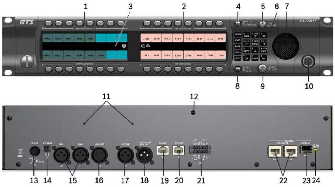
FIGURE 1. PAP-5032 Reference View
- Program Source Keys
- IFB Destination Keys
- High Resolution, Wide-Angle LCD Display
- LSTM/HDST SEL Lever Key
- AUX VOLUME Knob/Menu Navigation
- Keypad
- Main Speaker (Front)
- CLR/SCRL Lever Key
- MAIN VOLUME Knob
- Headset Connector (Front Panel)
- Power Supply Bracket Mounting Holes
- Power Supply Cable Tie Mounting Hole
- POWER Connector
- SPEAKER Rear Connector (2-position Terminal Block)
- AUX 1 and AUX 2 Connector
- HEADSET Connector (Rear Panel)
- EXT MIC Connector – Not Supported
- LINE OUT/MIC OUT Connector
- FRAME Connector
- EXP/LCP Connector (LCP not supported)
- GPIO Connector (12-position Terminal Block)
-
OMNEO ETHERNET Connector (See "Ethernet Connector" on page 30)
-
OMNEO OPTICAL (fiber) Connector
SM SFP Module (F.01U.278.502)
MM SFP Module (F.01U.278.503) - OMNEO OPTICAL DETECT (fiber) Indicator LED
Connector pinouts
| Power Supply: J1 | |
| Pin Assignment | |
| Pin 1 24 VDC | |
| Pin 2 GND | |
| Pin 3 Chassis GND | |
| Rear Speaker: J2 | |
| Pin Assignment | |
| Pin 1 Rear Speaker - | |
| Pin 2 Rear Speaker + | |
| Aux 1: J3 | |
| Pin Assignment | |
| Pin 1 GND | |
| Pin 2 AUX 1 IN | + |
| Pin 3 AUX 1 IN | - |
| AUX 2: J4 | |
| Pin Assignment | |
| 1 | GND |
| 2 | AUX 2 IN + |
| 3 | AUX 2 IN - |
| Rear Headset: J5 | |
| Pin Assignment | |
| 1 REAR_HS_MIC_IN - | |
| 2 REAR_HS_MIC_IN + | |
| 3 REAR_HS_COMMON | |
| 4 REAR_HS_L_OUT | |
| 5 REAR_HS_R_OUT | |
| MIC OUT/LINE OUT: J7 | |
| Pin Assignment | |
| 1 | GND |
| 2 MIC_OUT/LINE_OUT + | |
| 3 MIC_OUT/LINE_OUT - | |
| Matrix Connector: J8^a | ||
| Pin RJ-45 RJ-12 | ||
| 1 RS485 - | ||
| 2 RS485 - | RS485 - | |
| 3 FROM MATRIX + | FROM MATRIX + | |
| 4 TO MATRIX + | TO MATRIX + | |
| 5 TO MATRIX - | TO MATRIX - | |
| 6 FROM MATRIX - | FROM MATRIX - | |
| 7 RS485 + | RS485 + | |
| 8 RS485- | ||
a. Supports 568B and USOC wiring
| EXP/LCP Connector: J9 | |
| Pin Assignment | |
| 1 | LCP_DATA_STROBE |
| 2 | LCP_DATA_CLK |
| 3 | LCP_DATA_IN |
| 4 | GND |
| 5 | GND |
| 6 | |
| 7 | RS485 + |
| 8 | RS485 - |
| GPIO Connector: J10 | ||
| Pin | Assignment | Silk Screen |
| RLY 2/ OPT 2 | ||
| 1 | Chassis GND | |
| 2 | OPTO2_CATHODE | K- |
| 3 | OPTO2_ANODE | A+ |
| 4 | RELAY2_NO | NO |
| 5 | RELAY2_NC | NC |
| 6 | RELAY2_COM | C |
| RLY 1/ OPT 1 | ||
| 7 | Chassis GND | |
| 8 | OPTO1_CATHODE | K- |
| 9 | OPTO1_ANODE | A+ |
| 10 | RELAY1_NO | NO |
| 11 | RELAY1_NC | NC |
| 12 | RELAY1_COM | C |
| ETHERNET: J12 | |
| Pin Assignment | |
| 1 Data 1 + | |
| 2 Data 1 - | |
| 3 Data 2 + | |
| 4 Data 3 + | |
| 5 Data 3 - | |
| 6 Data 2- | |
| 7 Data 4+ | |
| 8 Data 4- | |
| ETHERNET: J11 | |
| Pin Assignment | |
| 1 Data 1 + | |
| 2 Data 1 - | |
| 3 Data 2 + | |
| 4 Data 3 + | |
| 5 Data 3 - | |
| 6 Data 2- | |
| 7 Data 4+ | |
| 8 Data 4- | |
| Front Headset | |||
| Pin | Assignment | ||
| 4-Pin 5-Pin 6-Pin | |||
| 1 FRONT_HS_MIC_IN- FRONT_HS_MIC_IN- FRONT_HS_MIC_IN- | |||
| 2 FRONT_HS_MIC_IN+ FRONT_HS_MIC_IN+ FRONT_HS_MIC_IN+ | |||
| 3 FRONT_HS_COMMON FRONT_HS_COMMON MON FRONT_HS_COMMON | |||
| 4 FRONT_HS_L_OUT FRONT_HS_L_OUT FRONT_HS_L_OUT | |||
| 5 FRONT_HS_R_OUT FRONT_HS_R_OUT | |||
| 6 | No Connect | ||
Requirements
The following panel firmware versions are needed for the specified PAP-5032 model:
AZedit...... Version 5.4.0 or later
IPedit...... Version 3.6.0 or later
MCII-e..... Version 3.4.0 or later
AIO-16..... Version 1.7.0 or later (if using AIO-16 to connect to a PAP-5032)
RVON-8/16..... Version 2.7.0 or later (if using RVON-8/16 to connect to a PAP-5032)
FWUT...... Version 5.40 or later
OMI ...... Version 6.3.x or later (if using OMI to connect to a PAP-5032)
PAP-5032 installation
IMPORTANT:
If you plan to use the Power Supply Mounting Bracket, we recommend you install the mounting bracket before cabling the panel. For information on different power supply mounting options, see "Power Supply Mounting Options" on page 129.
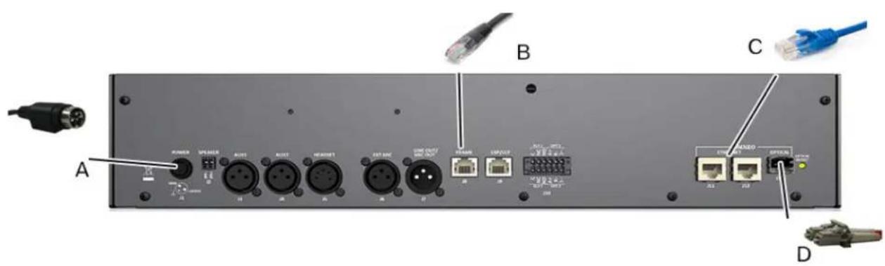
FIGURE 2. Rear Panel Connections
To install the PAP-5032, do the following:
- On the rear panel, plug the 24 VDC power connector (A) of the power supply into the power connector on the back panel of the unit.
- Connect an RJ-45 (568B or USOC) cable (B) with RTS cabling to the J8 FRAME connector (AIO). OR
Connect a CAT-5e cable (C) to either J11 or J12 ETHERNET connector (OMNEO CAT-5e).
OR
Connect a fiber connector (D) to the OPTICAL fiber connector on the rear panel (OMNEO Fiber).
NOTE: The PAP-5032 can have both AIO and Ethernet connected simultaneously, and the user can switch between the connections using the menus.
- Once the unit is cabled, plug the power supply power cord into the wall outlet or a power strip.
Rack mount considerations
| Elevated Operating Ambient | If installed in a closed or multi-unit rack assembly, the operating ambient temperature of the rack environment may be greater than room ambient. Therefore, consideration should be given to installing the equipment in an environment compatible with the Tma (Maximum Ambient Temperature) specified by the manufacturer. |
| Reduced Air Flow | Installation of the equipment in a rack should be such that the amount of air flow required for safe operation of the equipment is not compromised. |
| Mechanical Loading | Mounting of the equipment in the rack should be such that a hazardous condition is not achieved due to uneven mechanical loading. |
| Circuit Overloading | Consideration should be given to the connection of the equipment to the supply circuit and the effect that overloading of the circuits might have on overcurrent protection and supply wiring. Appropriate consideration of equipment nameplate ratings should be used when addressing this concern. |
| Reliable Earthing | Reliable earthing of rack mounted equipment should be maintained. Particular attention should be given to supply connections other than direct connections to the branch circuit (for example, the use of power strips). |
Configure the maximum number of PAP-5032 panels
Before connecting the PAP-5032 to the intercom system, the maximum number of PAP-5032 units connected to the intercom system must be defined.
To configure the maximum number of PAP-5032 units, do the following:
IMPORTANT: Be sure to save the configuration file before performing this task. Making modifications to the intercom configuration creates a new configuration file.
- Open AZedit.
- Save the current configuration file.
- From the Options menu, select Intercom Configuration... A Warning message appears.
- Click Ok.
The Intercom Configuration window appears.
- In the PAP-5032s field, enter the number of PAP-5032 units planned for the intercom system.
- Click Test
The Intercom Resizing Test Results window appears. A success or failure message appears.
- Click Ok.
The Intercom Resizing Test Results window disappears.
- Click Ok.
The new configuration file is written.
- Load the configuration file previously saved.
Assign the PAP-5032 to a port
NOTE: The port number chosen must agree with the intended connection type: AIO, OMNEO, or RVON. If using an OMNEO or RVON port, a connection must be made with IPedit.
To assign the PAP-5032 to a port, do the following:
- From the Options menu, select PAP-5032 Mapping Table... The PAP-5032 Mapping Table screen opens.
- Enter a port number in the field for the appropriate PAP-5032.
- Enter port numbers in the remaining fields, if necessary.
- Click Apply. A confirmation message appears.
- Click Ok.
- Click Cancel. The PAP-5032 Mapping Table window closes.
NOTE: If a PAP-5032 is connected to a port that is not configured for the PAP-5032, the panel displays a warning message.
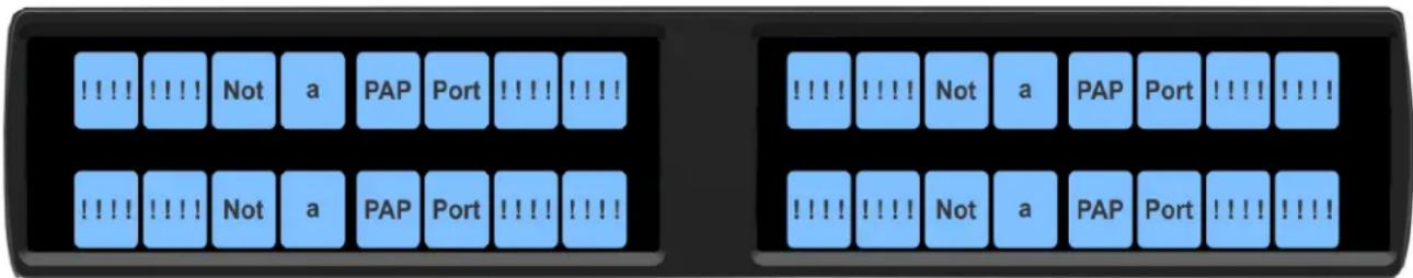
FIGURE 3. PAP-5032 Connection Warning Message
Assign keys to the PAP-5032
Key assignment in AZedit
NOTE: The PAP-5032 does not need to be connected to the Intercom System to assign keys in AZedit.
To assign keys to the PAP-5032 using AZedit, do the following:
- From the System menu, select PAP-5032 Assignment. The PAP-5032s window opens.
- Enter the PAP-5032 number. OR Enter the port number assigned to the PAP-5032. OR Select the port alpha assigned to the PAP-5032.
- Right-click a program input field.
- Select Change Assignment. The Select Key Assignment screen opens.
- Select Ports from the Type column.
- Select an assignment from the key assignment column.
- Click Select.
- Repeat program input assignment as necessary.
-
Right-click an IFB field.
-
Select Change Assignment.
The Select Key Assignment screen opens. - Select either IFBs or Special Functions from the Type column.
- Select an assignment from the key assignment column.
- Click Select.
- Repeat IFB assignment necessary.
- Send the changes to the intercom.
Connect the PAP-5032 to the Intercom
The PAP-5032 panel connects to an intercom using an OMNEO, RVON, or AIO connection.
IMPORTANT: The PAP-5032 cannot connect to the PAP/LCP/GPIO connector on the MCII-e on the ADAM frame or ODIN frame.
Connect via OMNEO
The PAP-5032 can establish can establish an OMNEO connection with either an OMI card in an ADAM or ADAM-M intercom, or directly to an ODIN intercom. Configuring an OMNEO connection to a PAP-5032 is similar to configuring an OMNEO connection to a KP-Series keypanel. The only differences between the two types of connections are:
• The PAP-5032 uses the device type EPAP, instead of OKP-2 or OKP-8.
- The PAP-5032 establishes a one-way audio connection (OMI/ODIN to PAP-5032) instead of the two-way connection established by the KP-Series keypanels.
You can configure the OMNEO connection settings of an OMI card or ODIN intercom using either AZedit or IPedit; however only IPedit or the panel menus can be used to configure the PAP-5032.
Name devices
IMPORTANT: If the OMI card or the PAP-5032 panel device name is changed, this causes the device to reboot. It also severs any OMNEO connections configured to connect using the old name. It is not necessary to change the device name. If a change is needed, it is best to change the name early in the set up process because there are less devices that need to be changed as a consequence.
Configure the OMI card using AZedit
Name the OMI card in AZedit
To name the OMI, do the following:
- From the Status menu, select I/O Cards. The I/O Cards window opens.
- Right-click the desired OMI card. A popup menu appears.
- Select OMNEO Configuration. The OMNEO Configuration window opens.
- In the Device Name field, enter a unique device name.
- Click Apply. The OMNEO Configuration window closes.
Configure the OMI connection to the PAP-5032 via AZedit
To configure the OMI to connect to the PAP-5032, do the following:
-
From the Status menu, select I/O Cards. The I/O Cards window opens.
-
Right-click the desired OMI card. A popup menu appears.
-
Select OMNEO Configuration. The OMNEO Configuration window opens.
-
From the OMNEO card drop down menu, select the slot number where the OMI card is located in the frame. The Device Name field auto-populates with the device name.
-
From the Local Channel drop down menu, select the channel the keypanel uses to communicate across the network. NOTE: An asterisk appears next to channels that are not configured to connect to another device.
-
In the Partner Device Name field, enter the name of the PAP-5032 in which a communication connection is established. OR Click the browse button to select from a list of devices. The Partner IP Address field auto-populates.
-
From the Partner Device Type drop down menu, select the type of device to which the OMI card connects. For a PAP-5032 panel, select the device type EPAP.
-
From the Partner Channel drop down menu, select the channel on the device to which the OMI communicates. For normal communications, select channel 1 (OMNEO channel 2 can be used for an auxiliary audio connection to the PAP-5032).
-
Click Apply to send the changes to all cards in the intercom.
Configure the OMI via IPedit
Add the OMI Card to the Device Catalog
To add the OMI to the device catalog. do the following:
-
From the Device menu, select Add. The Add Device window opens.
-
From the Available Devices pane, select the OMI card. The Add button becomes active.
-
Click Add. The OMI card appears in the device catalog.
-
Click Done. The Add Devices window closes.
Configure the OMI card setting via IPedit
To configure the OMI card via IPedit, do the following:
- Select the OMI card from the Device Catalog. The Device Information pane and Channel Configuration pane populates.
Device Information Pane
- Change the device name and description, if needed. This step is only needed once per OMI card.
Channel Configuration Pane
- Enter the destination device manually.
a. Enter a description in the Channel Description field, if needed.
b. Select EPAP from the Destination Type drop down menu.
c. Enter the device name of the PAP-5032 in the Destination Device Name field.
OR
Click the Browse button to select the PAP-5032.
a. Press the Destination Device name browse button.
b. Expand the tree to view available devices.
c. Select the PAP-5032 panel.
d. Click OK.
-
Set the Destination Channel to channel 1 (Channel 2 is used for an auxiliary audio connection to the PAP-5032).
-
Send Changes to the intercom.
Configure ODIN OMNEO connection via AZedit
To configure an ODIN OMNEO channel to connect to the PAP-5032 panel, do the following:
- From the System menu, select PAP-5032 Assignment. The PAP-5032 Assignment window opens.
- Select the desired port/alpha from either the Port drop down menu or Alpha drop down menu.
If the port does not appear in the PAP-5032 list, it has not been configured as a PAP-5032 port.
To configure an ODIN OMNEO channel to connect to a non-configured PAP-5032 port, do the following:
-
From the System menu, select Keypanel Assignment. The Keypanel/Ports window opens.
-
Select the desired port or alpha to use.
-
Click the Edit button. The Keypanel/Port Configuration window opens.
-
Click the OMNEO tab. The OMNEO page opens.
-
Enter a channel description in the Channel Settings Description field, if needed.
-
Enter the PAP-5032 name in the Device Name field. OR
Click the Device Name browse button, and then select the PAP-5032 from the available devices list.
-
Select EPAP from the Device Type drop down menu.
-
Select 1 from the Channel drop down menu. (Channel 2 is used for an auxiliary audio connection to the PAP-5032).
-
Select the latency from the Rx Latency drop down menu.
-
Click Done.
-
Send Changes to the intercom.
Configure an ODIN OMNEO connection using IPedit
Add an ODIN to the Device Catalog
To add the ODIN to the device catalog. do the following:
- From the Device menu, select Add. The Add Device window opens.
-
From the Available Devices pane, select the ODIN frame. The Add button becomes active.
-
Click Add. The ODIN frame appears in the device catalog.
-
Click Done. The Add Devices window closes.
Configure an ODIN OMNEO connection via IPedit
To configure an ODIN OMNEO connection via IPedit, do the following:
- Select the ODIN from the Device Catalog. The Device Information pane and Channel Configuration pane populates.
Device Information Pane
- Change the device name and description, if needed. This step is only needed once per ODIN frame.
Channel Configuration Pane
- Enter the destination device manually
a. Enter a description in the Channel Description field, if needed.
b. Select EPAP from the Destination Type drop down menu.
c. Enter the device name of the PAP-5032 in the Destination Device Name field.
OR
Click the Browse button to select the PAP-5032.
a. Press the Destination Device Name browse button.
b. Expand the tree to view available devices.
c. Select the PAP-5032 panel.
d. Click OK.
-
Set the Destination Channel to channel 1 (Channel 2 is used for an auxiliary audio connection to the PAP-5032).
-
Send Changes to the intercom.
Configure the PAP-5032 panel in IPedit
Add the PAP-5032 to the Device Catalog
To add the OMI to the device catalog. do the following:
- From the Device menu, select Add. The Add Device window opens.
- From the Available Devices pane, select the PAP-5032 Panel. The Add button becomes active.
- Click Add. The PAP-5032 Panel appears in the device catalog.
- Click Done. The Add Devices window closes.
Configure the PAP-5032 connection via IPedit
To configure an ODIN OMNEO connection via IPedit, do the following:
- Select the ODIN OMNEO entry from the Device Catalog. The Device Information pane and Channel Configuration pane populates.
Device Information Pane
- Change the device name and description, if needed. This step is only needed once per ODIN frame.
Channel Configuration Pane
- Enter the destination device manually.
a. Enter a description in the Channel Description field, if needed.
b. Select EPAP from the Destination Type drop down menu.
c. Enter the device name of the PAP-5032 in the Destination Device Name field.
OR
Click the Browse button to select the PAP-5032.
a. Press the Destination Device name browse button.
b. Expand the tree to view available devices.
c. Select the PAP-5032 panel.
d. Click OK.
-
Set the Destination Channel to channel 1 (Channel 2 is used for an auxiliary audio connection to the PAP-5032).
-
Send Changes to the intercom.
Connecting PAP-5032 panels through the OMNEO Offers menu
IMPORTANT: If IPedit is used to set up the panel connection, this step is not needed because it was already done in the software.
To finish the connection set up, the panel must be configured to talk with the OMI card or ODIN frame. This is done through the OMNEO Offers menu on the PAP-5032 panel. For more information, see “Menu System, OMNEO Offers” on page 94.
To choose an available OMNEO connection from the PAP-5032 front panel, do the following:
- Press the MENU button on the keypad.
The Menu appears in the display panel. - Navigate to the OMNEO Offers|Keypanel menu, select EPAP.
- Press the SEL button.
A list of available OMNEO offers appear. - Press the SEL button.
An arrow appears next to the device. -
Press and hold the CLR button to exit menu mode.
The panel connects using the selected OMNEO offer. -
Using the up/down keypad keys (or the AUX VOL encoder), select the OMNEO offer you want to use.
OMNEO audio input on the matrix available for other uses
The PAP-5032 only establishes a one-way OMNEO audio flow from the matrix to the PAP-5032 panel. The other half of the OMNEO port connecting to the PAP-5032 (audio flow from an OMNEO device to the matrix) can be used by another device that only sends audio to the matrix. This connection is configured using the Dante Controller application.
Data only OMNEO connection
If the network path between the PAP-5032 and the matrix it connects to is too long to meet the latency requirements for OMNEO audio, the panel can be configured to use a data-only OMNEO connection. The PAP-5032 panel functions normally, but audio monitoring does not work (since there is no audio connection). To set up a data-only connection to a PAP-5032, select EPAP-D (Ethernet PAP Data-only) for the partner device type when configuring the OMI or ODIN channels in AZedit and IPedit.
When a PAP-5032 panel is connected with the data only OMNEO connection, a data only icon appears in the left LCD display immediately to the left of the OMNEO connection icon.

Indicates the PAP-5032 does not have an audio connection to the intercom port used by the panel, as a result, listening to program source and IFB keys are disabled.
If the intercom has RVON ports available, using an RVON connection may be preferable to an OMNEO data-only connection, as an RVON connection permits the PAP-5032 panel to provide audio monitoring regardless of the network delay.
Connect via RVON
In order to connect using RVON, the factory installed firmware that comes with the PAP-5032 must be replaced with the RVON version which can be downloaded at www.rtsintercoms.com. For information on using FWUT (Firmware Upload Tool), see “Download Firmware to the Panel Using the Firmware Upload Tool” on page 64.
Configuration of an RVON connection to a PAP-5032 is similar to the RVON to KP-Series keypanel configuration. The only difference is the PAP-5032 uses device type EPAP-R instead of RVON-KP. RVON audio connections are normally bi-directional, but the PAP-5032 only receives audio from the OMI card or ODIN frame. It always sends silence in the other direction.
The PAP-5032 can connect to RVON-8, RVON-16, and ODIN frames.
Configure the RVON-8 or RVON-16 card via AZedit
Configure the RVON card settings in AZedit
To configure the RVON card settings in AZedit, do the following:
- From the Status menu, select I/O Cards.
The I/O Card Status window opens. - Right-click the desired RVON-8 or RVON-16 card.
A popup menu appears. - Select RVON Configuration.
The RVON Configuration window opens. - Select the appropriate slot from the RVON Card drop down menu.
- Select the Use Static IP Settings check box.
- Enter the IP Address.
- Enter the Network Mask.
- Enter the Default Gateway, if needed.
- Click Apply.
The RVON Configuration window closes.
Configure the RVON-8/16 connection to the PAP-5032 via AZedit
To configure the RVON-8/16 channel to connect to the PAP-5032, do the following:
- From the Status menu, select I/O Cards.
The I/O Card Status window opens. - Right-click on the RVON card to configure.
A popup menu appears. - Select RVON Configuration.
The RVON Configuration window opens. - Select the slot number where the RVON card is located in the frame.
The IP settings for this card display in the Settings for RVON Card section. - Select the channel you want to use to communicate to the PAP-5032 across the network.
NOTE: Channels not already configured to connect to another device appear with an asterisk.
-
Enter the IP Address of the PAP-5032 panel in the Partner IP Address field.
-
Select EPAP-R from the Partner Device Type drop down menu.
-
Select the channel on the partner device to which the RVON communicates from the Partner Channel drop down menu.
For normal communications with a PAP-5032 panel, select channel 1. RVON channel 2 is used for an auxiliary audio connection to the PAP-5032.
- Click Apply to send the changes to all the cards in the intercom.
Configure the RVON card via IPedit
Add an RVON card to the Device Catalog
To add an RVON card to the device catalog. do the following:
- From the Device menu, select Add.
The Add Device window opens.
- From the Available Devices pane, select the RVON card.
The Add button becomes active.
- Click Add.
The RVON card appears in the device catalog.
- Click Done.
The Add Devices window closes.
Configure an RVON card settings via IPedit
To configure an RVON card via IPedit, do the following:
- Select the RVON card from the Device Catalog.
The Device Information pane and Channel Configuration pane populates.
Device Information Pane
-
Change the description, if needed.
-
Change the IP settings (IP Address, Netmask, Gateway, and DNS Server), if needed.
This step is only needed once per RVON card.
Channel Configuration Pane
-
Enter a description in the Channel Description field, if needed.
-
Enter the destination device manually:
a. Select EPAP-R from the Destination Type drop down menu.
b. Enter the IP Address of the PAP-5032 panel.
The Destination Description field automatically populates if the PAP-5032 is connected to the network.
OR
Click the Browse button to select the PAP-5032:
a. Press the Destination Device Name browse button.
b. Expand the tree to view available devices.
c. Select the PAP-5032 panel.
d. Click OK.
-
Set the Destination Channel to channel 1 (Channel 2 is used for an auxiliary audio connection to the PAP-5032).
-
Send Changes to the intercom.
Configure ODIN RVON IP Settings via AZedit
To configure RVON IP settings for an ODIN frame, do the following:
-
From the Options menu, select Ethernet Configuration....
-
Select the RVON tab.
-
Enter the IP Address.
-
Enter the Netmask.
-
Enter the Gateway, if needed.
NOTE: This only needs to be done once for each ODIN frame.
Configure ODIN RVON Connection via AZedit
To configure an ODIN RVON channel to connect to a PAP-5032, do the following:
- From the System menu, select PAP-5032 Assignment.
The PAP-5032 Assignment window opens. - Select the desired port/alpha from either the Port drop down menu or Alpha drop down menu.
If the port does not appear in the PAP-5032 list, it has not been configured as a PAP-5032 port.
To configure an ODIN RVON channel to connect to a non-configured PAP-5032 port, do the following:
-
From the System menu, select Keypanel Assignment. The Keypanel/Ports window opens.
-
Select the desired port or alpha to use.
-
Click the Edit button. The Keypanel/Port Configuration window opens.
-
Click the RVON tab. The RVON page opens.
-
Enter the Partner IP Address in the IP Address field.
-
Select EPAP-R from the Device Type drop down menu.
-
Select 1 from the Channel drop down menu. RVON channel 2 can be used for an auxiliary audio connection to the PAP-5032.
-
Select either G.711 mu-law or G.711 a-law from the CODEC Type drop down menu.
-
Optionally, set the packet size, Enable VAD, and set the VAD threshold.
-
Click Done.
-
Send Changes to the intercom.
Configure ODIN RVON connection via IPedit
Add the ODIN frame to the Device Catalog in IPedit
To add the ODIN to IPedit, do the following:
- From the Device menu, select Add. The Add Device window appears.
- Select the ODIN RVON entry. The Add button becomes active.
- Click Add. The ODIN frame appears in the Device Catalog.
- Click Done. The Add Devices window closes.
Configure the ODIN frame RVON IP settings in IPedit
To configure the ODIN RVON frame in IPedit, do the following:
- Select the ODIN RVON entry from the Device Catalog. The Device Information pane and Channel Configuration pane populates.
Device Information Pane
-
Change the description, if needed.
-
Change the IP settings (IP Address, Netmask, Gateway, and DNS Server), if needed. This step is only needed once per ODIN RVON port.
Channel Configuration Pane
- Verify the RVON tab is selected above the Channel Configuration Column.
- Enter a description in the Channel Description field, if needed.
- Enter the destination device manually:
a. Select EPAP-R from the Destination Type drop down menu.
b. Enter the IP Address of the PAP-5032 panel.
The Destination Description field automatically populates if the PAP-5032 is connected to the network.
OR
Click the Browse button to select the PAP-5032:
a. Press the Destination Device Name browse button.
b. Expand the tree to view available devices.
c. Select the PAP-5032 panel.
d. Click OK.
-
Set the Destination Channel to channel 1 (Channel 2 is used for an auxiliary audio connection to the PAP-5032).
-
Send Changes to the intercom.
Configure the PAP-5032 panel in IPedit
Add the PAP-5032 to the Device Catalog in IPedit
To add the PAP-5032 to IPedit, do the following:
- From the Device menu, select Add. The Add Device window appears.
- Select the PAP-5032. The Add button becomes active.
- Click Add. The PAP-5032 appears in the Device Catalog.
- Click Done. The Add Devices window closes.
To configure the PAP-5032 in IPedit, do the following:
- Select the PAP-5032 from the Device Catalog. The Device Information pane and Channel Configuration pane populates.
Device Information Pane
-
Change the description, if needed.
-
Change the IP settings (IP Address, Netmask, Gateway, and DNS Server), if needed.
- Select the Use Static IP Settings check box is selected, if needed.
- Verify the Use RSTP check box is selected, if needed.
- Verify the Enable AIO check box is not selected.
Channel Configuration Pane
- Verify the RVON tab is selected above the Channel Configuration Column.
- Enter a description in the Channel Description field, if needed.
- Enter the destination device manually:
a. Select RVON-8, RVON-16, or ODIN-R from the Destination Type drop down menu.
b. Enter the IP Address of the selected device.
The Destination Description field automatically populates if the PAP-5032 is connected to the network.
OR
Click the Browse button to select the appropriate device:
a. Press the Destination Device Name browse button.
b. Expand the tree to view available devices.
c. Select the appropriate device.
d. Click OK.
-
Select the channel to which the panel connects (this should correspond to the intercom port configured to connect to the PAP-5032 panel).
-
Send changes to the keypanel.
Connect the PAP-5032 panel through the front panel RVON offers menu
IMPORTANT:
If IPedit was used to set up the PAP-5032 panel end of the connection, this step is not needed because it has been done in the software.
To finish the connection setup, the keypanel must be configured to accept the RVON offer from the partner device. This is done using the RVON Offers menu. For more information, see “Menu System, RVON Offers” on page 95.
To select an RVON connection offer from the PAP-5032 front panel, do the following:
- Press the MENU button to invoke the main menu.
- Using the left and right arrow keypad key or the AUX Vol encoder, navigate to RVON Offers.
- Press the SEL button.
- Navigate to Keypanel.
- Press the SEL button.
- Navigate to EPAP-R.
- Press the SEL button.
A list of available RVON offers appear. - Using the up/down keypanel keys or the AUX VOL encoder, navigate to the desired RVON offer.
- Press the SEL button.
An arrow appears next to the offer. - Press and hold the CLR button to exit menu mode.
The panel connects using the selected RVON offer.
Connect via AIO
The PAP-5032 can connect using a direct AIO connection to the following:
• AIO-16 card with an MDR backcard in ADAM or ADAM-M
• AIO-16 card with an RJ-45 backcard in ADAM-M
• ODIN frame (using one of the AIO RJ-45 ports on J4)
These connections all support automatic addressing. It is not possible to set the serial address of the PAP-5032.
The PAP-5032 cannot connect to an AIO-8 card, nor can it connect to an AIO-16 with a SCSI backcard. These cards do not support the 8-bit protocol that the PAP-5032 requires.
Other AIO Port Audio Input Uses
The PAP-5032 only uses audio sent from the matrix. It never sends audio to the matrix (other than silence). The AIO port connecting to the PAP-5032 can be shared with another device that only sends audio to the matrix. This requires a custom cable to connect the signals TO_MATRIX+ and TO_MATRIX- to the other audio source instead of the PAP-5032 panel. For more information, see “Connector pinouts” on page 13.
Key assignment from the PAP-5032
NOTE: The PAP-5032 must be connected to the Intercom System to assign keys from the front panel.
To assign a key from the front panel, do the following:
- Press the MENU key.
- Select Key Assign.
- Press SEL.
-
Select PGM Source (P2P). OR Select IFB.
-
Press SEL.
-
Select the source to assign to the key.
-
Press SEL.
-
Press the physical key to make the assignment.
To assign a key from the front panel keypad, do the following:
-
On the keypad, press the PGM key.
A scroll list of PGM sources appears in the panel display.
OR
Press the IFB key.
A scroll list of IFB sources appears in the panel display. -
Select the desired source/IFB.
-
Press the COPY key.
-
Press the target key.
The source appears on the panel key.
NOTE: For both methods, reassigning a PGM source or IFB to the panel clears the existing assignment. Program sources may only be assigned to keys on the left hand side of the panel, and IFBs may only be assigned to keys on the right hand sided of the panel.
Power Up
At power-up, if the PAP-5032 is connected to the matrix, the alphanumeric display shows dashes in the light blue color key. After several seconds, the program source and IFB key assignments display with the appropriate color keys and alphas (if key assignments have been configured).
If the panel cannot establish communications with the intercom system, all alphanumeric displays continue to show asterisks (****) and the Disconnected from Matrix icon 4 DISCONNECTED FROM MATRIX appears in the panel display. If the panel is configured for OMNEO, this icon also displays the OMNEO device name. Check the panel to matrix cable connection if this occurs.
If the panel loses communications with the intercom, the panel displays the Disconnected from Matrix icon and displays asterisks after approximately 30 seconds.
If the PAP-5032 panel is able to connect to the intercom, but has been connected to an intercom port that has not been configured to connect to a PAP-5032 panel (for example, a normal keypanel port), it displays the message “!!!Not a PAP Port!!!”.
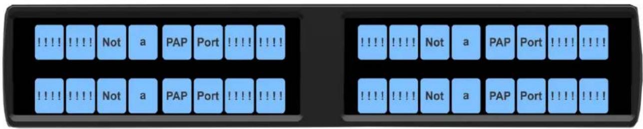
FIGURE 4. PAP-5032 Connection Warning Message
Connections
Frame Connector
Use the Frame connector to connect to the Matrix system. For the frame connector location, see Figure 1 on page 12. The intercom port you connect to should agree with the address set earlier.
Ethernet Connector
Use the Ethernet connector to connect the panel to a network system. Each RJ-45 Ethernet connector has two LEDs:
Left LED. The left LED is yellow and indicates a network link is established. It flashes on/off whenever there is network activity.
Right LED. The right LED is bi-color (orange and green) and indicates the speed of the connection by the color displayed.
• A green LED indicates the port is operating at 1000Mbps (1 Gbps).
- An orange LED indicates the port is operating at 100Mbps.
- No LED color indicates the port is operating at 10Mbps. This is not suitable for OMNEO networking.
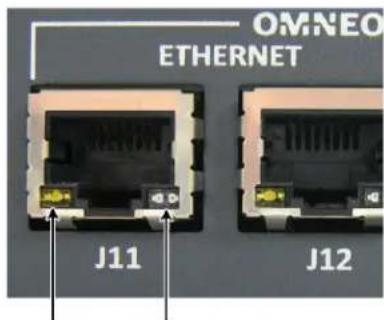
Left LED (yellow)
Right LED
(bi-color orange/green)
Headset Connector
A binaural headset may be connected to the front or rear of the unit for use along with or in place of the front/rear panel speaker and a separate microphone. Headphones may be connected for use with a separate microphone.
Female Headset Connector
For a female headset connector, the set screw access hole is located on the bottom-right side of the unit.
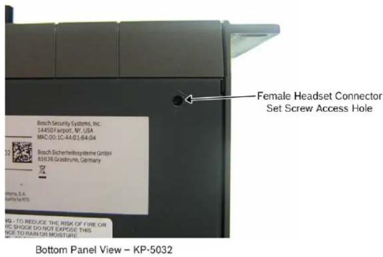
FIGURE 5. Female Headset Connector Set Screw Access Hole
Male Headset Connector
For a male headset connector, the set screw access hole is located on the right-side of the unit.
IMPORTANT: The right-side rack ear must be removed to expose the set screw access hole.
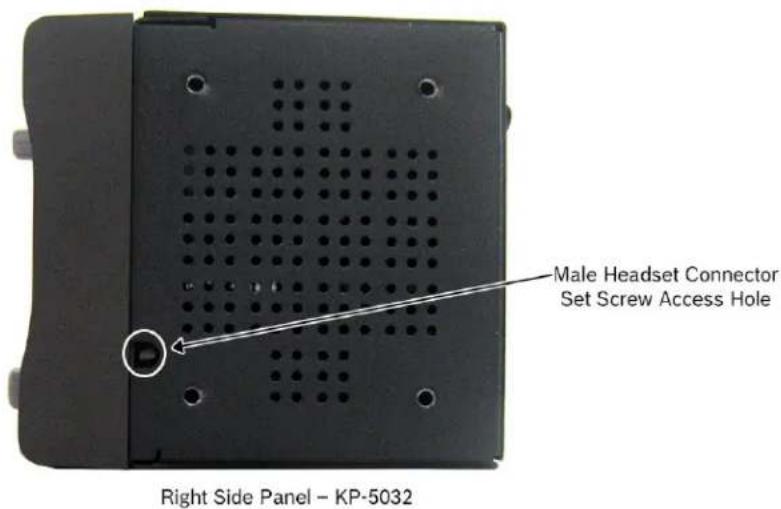
FIGURE 6. Male Headset Connector Set Screw Access Hole
Changing the Front Headset Connector
The front headset connector can be switched between a 5-/6-pin XLR connect and a 4-pin XLR connector.
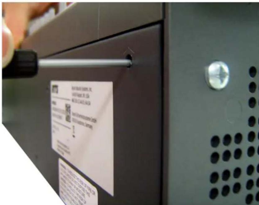
To replace the front panel headset connector, do the following:
- Using a flat-blade screwdriver with 2.4mm wide (3/32 in.) tip, turn the set screw counterclockwise to loosen the connector from the unit.
-
Once the connector is loose, tip the unit and gently shake the connector loose.
-
Carefully pull the headset cables free from the chassis.

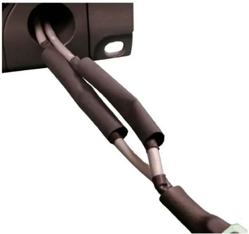
natural_image
Close-up of a mechanical cable or connector with braided cable and terminal block (no text or symbols visible)NOTE: If the cable assembly becomes caught, shift the cable up and down to clear the cable from the unit.
- Cut the shrink-tubing from around the cables. Take care to not cut through the cables.

natural_image
Close-up of hands holding a black and gray tool with a white tip, no visible text or symbols- Disconnect both cables by pulling the cable-to-cable connectors apart.

natural_image
Close-up of hands connecting two cables to a plug socket (no visible text or symbols)- Using the replacement headset connector, thread the cables through the supplied shrink-tubing.
IMPORTANT:
Using one piece of the shrink tubing, thread the long cable of the replacement connector.
Using the second piece of shrink tubing, thread the long cable protruding from the panel headset connector opening.

natural_image
Close-up of a black main volume device with attached metallic cable, showing ports and wiring (no text or symbols visible)- Connect the cable-to-cable connectors.
NOTE: Take care to reconnect the proper gender connectors when reassembling the headset cable.
- Position both pieces of shrink-tubing so any portion of the cable without an outer insulation layer is covered.
natural_image
Close-up of a black and white electrical plug with coiled wires, no visible text or symbols- Using a heat gun, apply even heat over the length and diameter of the tubing (minimum temperature 100^ C).
IMPORTANT:
Since uncontrolled heat can cause uneven shrinkage, physical damage, and insulation failure, the use of open flame is not recommended. Avoid overheating the heat shrink-tubing because it can become brittle and/or charred.
- Gently push the headset connector cable back into the unit.
- Align the rib on the headset connector with the notch in the connector opening and press the connector completely in.
- While holding the connector in place, turn the set screw clockwise to tighten the connector in position.
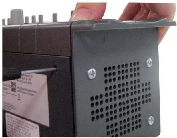
natural_image
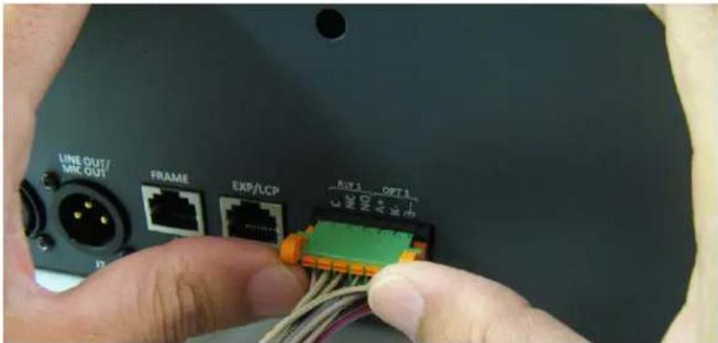
Close-up of a hand holding a black electronic device with a perforated panel and screw holes (no visible text or symbols)GPIO 12-Position Terminal Block Connector
The GPIO 12-Position Terminal Block Connector is used to provide connections to relays (outputs) and opto-isolators (inputs). Using the table, "GPIO Connector: J10" on page 13, connect the correct wires to the 12-position connector.
Wire Specifications
Solid Wire: 26-16 AWG/0.13-1.5 mm ^2
Stranded Wire:26-16 AWG/0.13-1.5 mm²
To connect the 12-position terminal block to the panel, do the following:
-
Align the terminal block connector with the 12-position connector on the rear side of the panel.
-
Gently push the connector into place.
The locking levers click into place.
To detach the 12-position terminal block connector from the panel, do the following:
Using both thumbs, gently press up on the locking levers. The connector is released from the panel.
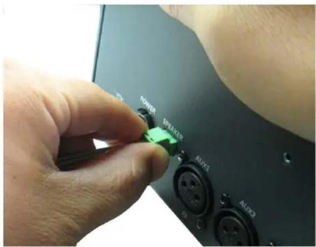
Speaker 2-Position Terminal Block Connector
The Speaker 2-Position Terminal Block Connector is used to connect an external speaker.
Wire Specifications
Solid Wire: 26-16 AWG/0.13-1.5 mm²
Stranded Wire: 26-16 AWG/0.13-1.5 mm²
Torque: 3.0 lb-IN/0.34 Nm
WARNING: The positive (+) and negative (-) terminals of the connector should be connected to the positive (+) and negative (-) terminals of the external speaker. These terminals should never be connected to GND or permanent damage can occur.
To connect the 2-position terminal block to the panel, do the following:
- Align the 2-position terminal block connector with the 2-position connector on the rear side of the panel.
- Gently push the connector into place.
To detach the 2-position terminal block connector from the panel, do the following:
Using the thumb and fore-finger, carefully wiggle the 2-position terminal block until is comes free from the connector.
Intercom Keys and Displays
Display Icons
Display Icons are used to indicate the accessories and features enabled, disabled, active, or inactive. Use Table 1 for a complete description of each icon seen on the PAP-5032.
TABLE 1. Display Icon Descriptions
| Icon Icon | Name Description | |
 | Matrix Connected | The panel is connected to the Matrix. This icon briefly displays at connection. |
 | Disconnected From Matrix | There is no connection between the Matrix and the panel. This icon is displayed as long as there is no Matrix data connection.NOTE: When the panel is disconnected, it displays its Device Name (for OMNEO) or IP Address (for RVON) device connections. |
 | Firmware Download | Firmware is being downloaded to the panel. A progress bar displays: chunk progress overall progress chunk/overall progressNOTE: For more information, see “Download Firmware to the Panel From AZedit” on page 61. |
 | Front Headphones | The front headphones are enabled. This indicates the front headset microphone is not enabled. |
 | Front Speaker | The front speaker is enabled.To enable the front speaker, see “Audio Options Menu, Speaker” on page 88. |
 | Front Speaker Muted | The front speaker is muted. |
 | Rear Headphones | The rear headphones are enabled. This indicates the rear headset mic is not enabled.To enable the rear headphones, see “Audio Options Menu, Headset Speaker” on page 85. |
 | Rear Speaker | The rear speaker is active.To activate the rear speaker, see “Audio Options Menu, Speaker” on page 88. |
 | Rear Speaker Muted | The rear speaker is muted. |
TABLE 1. Display Icon Descriptions
| Icon Icon Name Description | ||
 | Both Headphones | Both front and rear headphones are enabled. This indicates both the front and rear headset mics are disabled.To enable the front headphones, see “Audio Options Menu, Headset Speaker” on page 85. |
 | Both Speakers | Both front and rear speakers are enabled.To enable the front speaker, see “Audio Options Menu, Speaker” on page 88. |
 | Both Speakers Muted | Both front and rear speakers are muted. |
 | OMNEO Enabled | The OMNEO matrix interface is enabled on the panel. For more information on OMNEO Offers, see“Menu System, OMNEO Offers” on page 94. |
 | RVON Enabled | The RVON matrix interface is enabled on the panel. |
 | Analog | The Analog matrix interface is enabled on the panel. |
 | Virtual Key Assignment | Keys are active on a virtual EKP that are not being displayed. For more information, see “Key Options Menu, Panel Swap” on page 91.NOTE: A listen bar displays to indicate virtual keys are active. |
 | Matrix In Mute | The Matrix Input volume is muted. When the Matrix Input volume is adjusted down to mute, the panel displays this flashing icon as a warning there is no audio from the Matrix. |
 | Data Only Connection | Indicates the PAP-5032 does not have an audio connection to the intercom port used by the panel, as a result, listening to program source and IFB keys are disabled. |
Keypad Reference View
With the PAP-5032, there are two tiers of operation for a panel's keypad: Primary Mode and SHIFT Mode.
Primary Mode
Primary Mode is used for the most common panel functions, such as CLR, SEL, and accessing the Main menu. There are no special keypad sequences to use these functions.
SHIFT Mode
SHIFT Mode contains secondary functions used to access more utilities on the panel. The SHIFT mode functions are located on the primary keypad keys.
NOTE: By default, the keypad backlight changes to white when the keypad is in SHIFT mode. For more information, see "Service Menu, Keypad" on page 98.
To access SHIFT Mode, do the following:
- Press the SHIFT button.
- Press the SHIFT mode button desired.
NOTE: Once SHIFT mode is entered, exit the mode by pressing the SHIFT key again, without pressing any other keys.
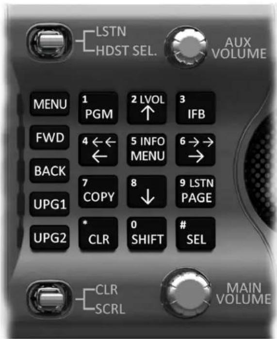
FIGURE 7. PAP-5032 Keypad
| IMPORTANT: | When SHIFT +appears in this manual, the user is instructed to press the SHIFT key followed by the next keypad key. The SHIFT key and the keypad key should not be pressed simultaneously. If the user is instructed to press two keys simultaneously, this manual uses the phrasepress and hold. |
| Keypad Button | Shift Function | Description |
| PGM | The PGM (1) button displays the list of available program sources available to scroll from. | |
| ↑button LVOL | The ↑(2) button moves you upward through the scroll list or available key assignments one at a time.The LVOL button is used to adjust the input gain for a program source or the output gain of an IFB.When adjusting a program source, the adjustment changes the input gain of the corresponding intercom port.When adjusting an IFB, the adjustment changes the output gain of the intercom port configured as the output port for the IFB. If the IFB does not have an output port configured, “N/A” is displayed in place of the numeric gain and the volume bar is not shown.Toadjust the listen volume from the front panel, do the following:1.Press the SHIFT+ LVOL (2) buttons.The prompt Select PGM or IFB Gain to Adjust appears in the display.2.Press a Program Source or IFB key.The current numeric gain and volume bar graph appear on the key assignment.3.Adjust the volume by rotating the AUX VOLUME encoder.The gain and bar graph reflect the change. | |
| IFB button | The IFB (3) button displays the list of available IFB assignments available to scroll from. Select an intercom name to access the scroll lists for that intercom | |
| ←button ←← | The ←/←← (4) button moves you backwards through the menu options or available key assignments one at a time or by the page. | |
| MENU button | INFO | The MENU/INFO (5) button is used to access the top level menu structure or access a secondary menu of commonly used features (see, “INFO button” on page 43).The MENU button is used to access the top-level menu structure.>Press the MENU button once.The top-level menu appears in the panel display.Toaccess the INFO menu, do the following1.Press the SHIFT button.2.Press the MENU/INFO (5) button.The INFO menu appears in the panel display.For more details about the INFO button, see “INFO button” on page 43. |
| →button →→ | The →/→→ (6) button moves you backwards through the menu options or available key assignments one at a time or by the page. | |
| COPY button↓button | The COPY (7) button is used to copy an incoming call key assignment from the CWW to a specific panel key.Tocopy a listen key to a listen key, do the following:1.Press COPY + SEL + SHIFT.2.Press the source key.3.Press SHIFT.4.Press the target key.The ↓(8) button moves you downward through the scroll list or available key assignments one at a time. | |
| PAGE button | LSTN | The PAGE button is used to access a different setup page. You can configure up to 15 pages in the intercom system. The default number of pages is four. To configure the number of pages available use the Intercom Configuration window, on the Options Page in AZedit.To program a new page directly, do the following:>Press the PAGE button, <#>, then tap a key.To enter the graphical page change mode, do the following:>Press the PAGE+ SEL buttons.ORPress the SHIFT+PAGE buttons. |
| The LSTN mode button is used to toggle push button presses from talk to listen key presses.NOTE: For more information on the push button listen mode, see “Basic Key Operation” on page 45.To enter the listen menu mode, do the following:1. Press the SHIFT+LSTN button.The push buttons switch to listen mode and a Toggle Key Listen States message appears on panel display2. Press the panel button for which to listen.The panel buttons now operate on listen key states rather than talk key states.NOTE: When not in listen menu mode (SHIFT+LSTN), holding the SHIFT button and pushing a panel button also toggles the listen state of the panel button pushed.To leave listen mode, do the following>Press the CLR button.The panel leaves listen mode. | ||
| CLR button | The CLR (*) button functions as a back button when a menu is displayed.To clear a menu, do the following:>Press and hold the CLR button for half a second. | |
| SHIFT button | The SHIFT (0) button accesses the secondary keypad actions such as INFO, LVOL, and LSTN.NOTE: The SHIFT button, when held down while pushing a panel key, toggles the listen state of the button. | |
| SEL button | The SEL (#) button is used to select options highlighted in the menu structure. |
PAP-5032 Only Keypad Keys
| Keypad Button | Shift Function | Description |
| MENU button | UPG3 | The MENU button is used to access the top-level menu structure.>Press the MENU button once.The top-level menu appears in the panel display.NOTE:If the keypad backlight mode is set to Activate (Service|Keypad|Backlight), you must press the MENU button twice to access the top-level menu. |
| FWD button | UPG4 | The FWD button moves you forward through the menu option highlighted. For example, if Display is highlighted in the panel display and FWD is pressed, the second level of the display menu appears. |
| BACK button | UPG5 | The BACK button moves you backward, one level, through the menu structure.NOTE:If you are at the top-level of the menu structure and press BACK, you cannot move backward any further. |
| UPG 1 button | UPG6 | The UPG1 button is used to assign a frequently used menu item. This allows users to access the menu item quickly. UPG buttons can also be programmed to trigger GPI outputs or panel swap events. |
| UPG 2 button | UPG7 | The UPG 2 button is used to assign a frequently used menu item. This allows users to access the menu item quickly. UPG buttons can also be programmed to trigger GPI outputs or panel swap events. |
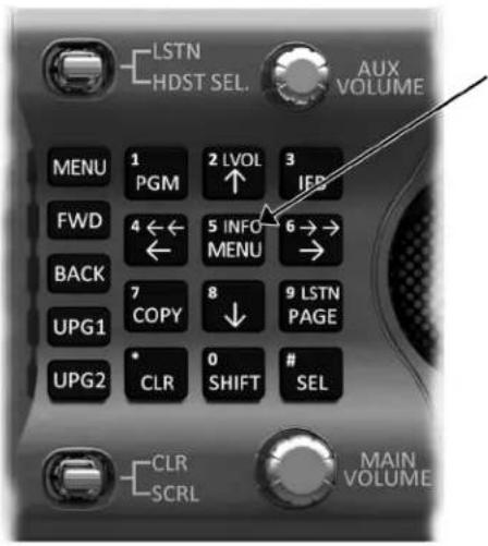
INFO button
The INFO button is used to access commonly used features and configuration options for the panels. These include the following:
| Feature Description | |
| Panel ID Displays the port number and alpha of the panel. | |
| Setup Pages | Displays the setup pages assigned to each row of keys. You cannot change setup pages from this menu. |
| MAC Address Displays the MAC Address of the panel. | |
| Test Panel | Enables the Test Panel feature. For more information, see “Service Menu, Test Panel” on page 107. |
| Version | Displays the firmware version of the PAP-5032. For more information, see “Display Menu, Version” on page 89. |
To access the Info Menu, do the following:
- On the keypad, press the SHIFT button.
- On the keypad, press the INFO MENU (5) button.
The INFO menu appears in the panel display.
NOTE: To exit the INFO menu mode, press the CLR button.
Breadcrumb Menu Navigation
Breadcrumb Navigation is a graphical aid to help users know where they are in the menu structure. The breadcrumb menu visually lays out a path of options selected up to the current menu position. It appears as a horizontal line above the menu options (shown in Figure 8). For more information, see “Service Menu, Display” on page 96.
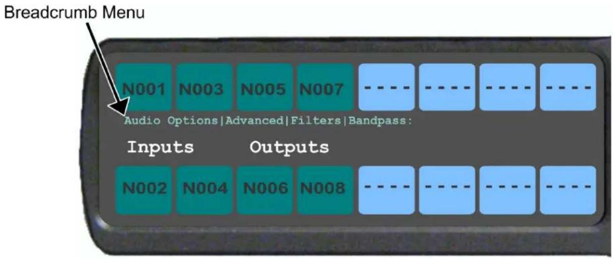
FIGURE 8. Breadcrumbs Navigation
Menu Navigation and Shaft Encoder Knobs
While the panel is in menu mode, the AUX Volume shaft encoder is used to move the selection left and right. In the case of a single menu item with up and down control, the shaft encoder is rotated to scroll through the available selections. This is particularly convenient when setting the panel brightness or gain. Also, pressing the Aux Volume shaft encoder while in menu mode is the equivalent to SEL key operation. Conversely, pressing the MAIN Volume shaft encoder in menu mode is the equivalent to the CLR key operation. Double-tapping the AUX Volume shaft encoder, can also be used for the CLR operation.
Other navigation options:
- Press and hold the AUX/MENU shaft encoder to exit the menu.
CLR Button
The CLR button is used either as the BACK function while in MENU mode or to exit MENU mode completely.
Togo back one menu level, do the following:
Press the CLR button once.
To exit the menu, do the following:
Press and hold the CLR button for half a second.
Basic Key Operation
Coupled with the traditional operation of pushbutton keys, the PAP-5032 panels also have an integrated LCP (Level Control Panel).
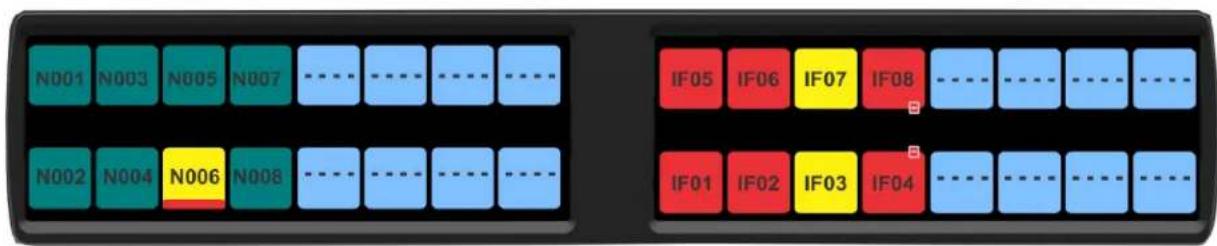
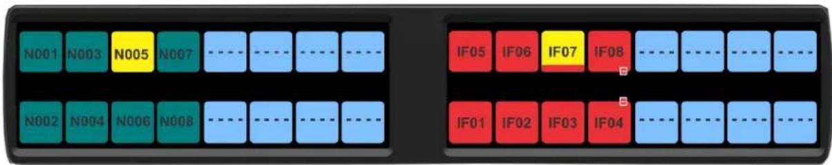
Program Sources and IFBs
The purpose of the PAP-5032 is to display and allow users to change which program sources are assigned as the program input for IFBs. There are two temporary states for the keys on the PAP-5032:

This key state is shown when the IFB or Program Source key is pressed or latched on and off.

This key state is shown when another key associated with the key is pressed. For example, when program source key is pressed, the IFB where the program source is assigned displays in a solid yellow.

When a minus icon appears on an IFB source key, this means the the IFB had not been associated with an output port. Program sources cannot be associated with the IFB because there is no output port to send the audio to.

FIGURE 9. Pushbutton Key Function Explanation
Key Assignment from the Front Panel
NOTE: The PAP-5032 must be connected to the Intercom System to assign keys from the front panel.
To assign a key from the front panel, do the following:
- Press the MENU key.
- Select Key Assign.
- Press SEL.
-
Select PGM Source (P2P). OR Select IFB.
-
Press SEL.
-
Select the source or IFB to assign to the key.
-
Press SEL.
-
Press the physical key to make the assignment.
Display IFB sources using a program source
To display the IFB sources associated to a program source, do the following:
Press and hold a PGM Source key.
The associated IFB sources appear in yellow.
Display program source associated to an IFB source
To display the program source associated to an IFB source, do the following:
Press and hold a PGM Source key.
The associated IFB sources appear in yellow.
Assign a program source to an IFB
To assign a program source to an IFB, do the following:
- Click and hold an IFB key.
- Press the program source key to assign to the IFB.
The program source is associated to the IFB.
Listen Indicator
The Listen Indicator, shown in Figure 10, displays a visual indicator when the listen key is active. The listen state of each key is represented by an LED-like horizontal bar at the top (listen) of each key.
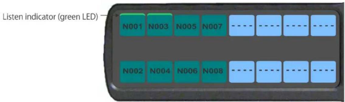
FIGURE 10. Listen Indicator
By default, the listen indicator is green. You can change the colors of the indicator by using the Key Color Window in AZedit. For more information, see "Panel Color Window" on page 54.
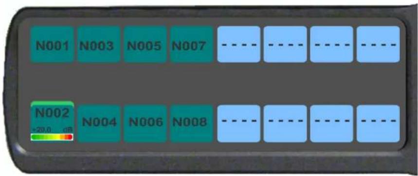
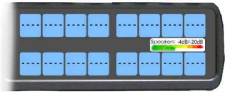
Input/Output Gain Adjustment
The PAP-5032 panel is used to adjust the input gain of program sources (ports) and the output gain of IFBs. This adjustment is automatically reflected in AZedit on the Input/Output Gains window (System|Gains|Input/Output Gains). Adjusting the output gain of an IFB changes the output gain of the port currently assigned as the output port for the IFB. If no port is configured as the output port, the gain cannot be adjusted (displayed as NA).
The range of input and output gain adjust is -20 dB to +20 dB.
To adjust an input gain or an output gain, do the following:
-
Press and hold SHIFT.
-
Press and hold the panel key for which you want to adjust the gain.
NOTE: Once you have pressed the panel key, you can release the SHIFT button.
-
While still pressing the panel key, rotate the AUX VOL encoder to set the gain.
-
Turn the AUX Volume shaft encoder to the right to increase the gain.
OR
Turn the AUX Volume shaft encoder to the left to decrease the gain.
A volume status bar (—) and the volume level, in dB, appear on the specified key in the panel display.
OR
- Press SHIFT + PAGE (LSTN).
Toggle Listen Key States appears on the panel display.
-
Press and hold the panel key for which you want to adjust the gain.
-
Turn the AUX Volume shaft encoder to the right to increase the gain.
OR
Turn the AUX Volume shaft encoder to the left to decrease the gain.
A volume status bar ( ) and the volume level, in dB, appear on the specified key in the panel display.
OR
- Press SHIFT + up arrow (LVOL).
Select PGM or IFB Gain to Adjust appears on the panel display.
-
Press the panel key for which you want to adjust the gain.
-
Rotate the AUX VOL encoder to set the gain.
-
Turn the AUX Volume shaft encoder to the right to increase the gain.
OR
Turn the AUX Volume shaft encoder to the left to decrease the gain.
A volume status bar (☐) and the volume level, in dB, appear on the specified key in the panel display.
NOTE: The volume bar shows a full width icon, but only colors the portion that represents volume. The remainder of the bar is shown in black. This is so when the key gains are always displayed, the user knows when a key is muted, as opposed to a key that cannot have gain adjusted.
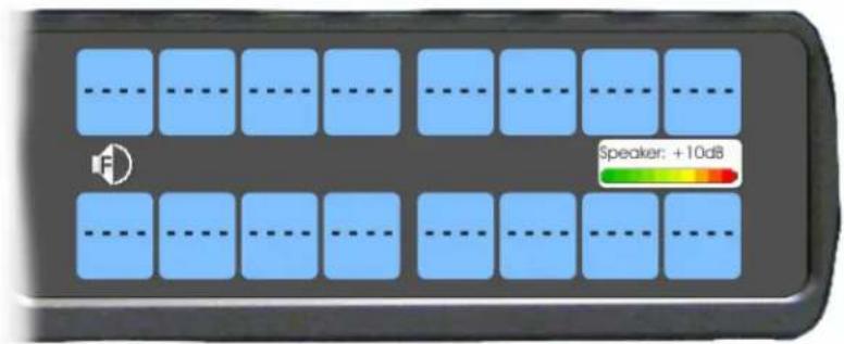
Panel Volume Adjustments
By default, the main volume control adjusts the output volume for the speaker (front/rear) or headset (front/rear), whichever is currently active.
IMPORTANT:
If the speaker output volume is adjusted to Mute, then the panel displays a flashing SPKR MUTE icon as a warning there is no audio to the front, rear, or both speakers.


If the headset output volume is adjusted down to Mute, then the panel displays a flashing HDST MUTE icon as a warning there is no audio to either the front, rear, or both headsets.


Output volume ranges from +10 dB to -48 dB and Mute for speakers, and +24 dB to -48 dB and Mute for headsets.
NOTE: When speakers and/or headset volumes are ganged together a split volume bar displays in the panel display. The front speaker or headset is the top portion of the bar, while the bottom portion of the bar is the rear speaker or headset volume.
For more information on Ganged Volumes, see "Audio Options Menu, Ganged Vols" on page 85.
To adjust output volume level, do the following:
On the panel, turn the MAIN VOLUME encoder to the right to increase the volume for the selected output. OR Turn the MAIN VOLUME encoder to the left to decrease the volume for the selected output.
NOTE: When the MAIN VOLUME encoder is turned, the volume level bar appears in the panel display.
NOTE: Volume adjustments can be saved as power-up defaults using "Menu System, Save Config" on page 95.
To select a different output volume control, do the following:
On the panel, push the MAIN VOLUME encoder once.
The main volume focus switches to the next available output and displays above the volume level bar.

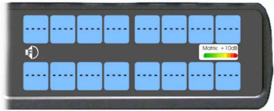
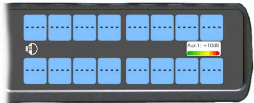
Aux Volume Adjustments
By default, the Aux Volume shaft encoder knob adjusts the selected input volume, which can include Aux 1–2, Matrix Input, or OMNEO 1-2, depending on whether the connection is via OMNEO or AIO. AUX input must be enabled and be mixed to a destination, otherwise it's volume cannot be adjusted.
Input volume ranges from +10 dB to -48 dB and Mute.
NOTE: When the Matrix Input volume is adjusted down to Mute, then the panel displays a flashing MTX MUTE icon as a warning there is no audio from the Matrix.

To adjust listen volume level, do the following:
On the panel, turn the AUX VOLUME encoder to the right to increase the volume for the selected input. OR
Turn the AUX VOLUME encoder to the left to decrease the volume for the selected input.
NOTE: When the AUX VOLUME encoder is turned, the volume level bar appears in the panel display.
NOTE:
• Volume adjustments can be saved as power-up defaults using "Menu System, Save Config" on page 95.
• The inputs are available if they are enabled and mixed to an output.
To change the focus of the volume control, do the following:
On the panel, push the AUX VOLUME shaft encoder once.
The aux volume focus switches to the next available input.
Setup Pages
Setup Pages are used to allow access to more key assignments than physical keys on the panel. This is useful for sharing a panel because setup pages can be used to swap between the key assignments used for each person. An alternative to Setup Pages is Panel Swap (see "Key Options Menu, Panel Swap" on page 91).
Up to 32 setup pages can be configured for program sources and for IFBs. Each Setup page has eight program source or eight IFB assignments.
NOTE: To add key assignments to the setup pages, see "Menu System, Key Assign Menu" on page 90.
To open and assign setup pages, do the following:
-
Press the PAGE key. The Page menu appears in the display screen.
-
Enter one or two digits (page number). OR Press SEL to enter graphical mode.
NOTE: By pressing SEL, you no longer have to complete Step 3.
- Tap a key to assign that page to the key row.
To toggle between setup pages, do the following:
IMPORTANT: You must be in graphical page mode to be able to toggle between pages.
- Using the left and right arrows, change the page on the current key group.
- Press the SEL key (or wait 2 seconds for auto-select to engage).
To change the highlighted key row in the graphical mode, do the following:
Using the FWD/BACK or UP/DOWN keys, change the highlighted key row.
To change the highlighted key group from program source keys to the IFB keys, do the following:
Press an IFB key. OR Press the SHIFT + RIGHT buttons.
To change the highlighted key group from IFB keys to program source keys, do the following:
Press a Program Source key. OR Press the SHIFT + LEFT buttons.
User Programmable Buttons
A UPG (User Programmable Button) gives you the option to assign frequently used menu items to a single button on the panel, eliminating the need to navigate through the menu structure. Not all menu items can be programmed to the UPG buttons, such as any assignment group menu, any TIF menu items, or scrolling menu items. Basically, any menu that requires context or history cannot be saved. If a menu item cannot be saved, a prompt appears in the panel display showing Cannot save this menu position.
NOTE: You can program a UPG key to activate the screen saver option on the panel. For more information, see “To activate the screen saver from a UPG key” on page 53.
The UPG keys can also be used to activate relays. When a relay is assigned to the button, and while the panel is not in menu mode, pressing the UPG key activates the relay for as long as the UPG button is held down. Once the button is released, the relay becomes inactive.
NOTE: The UPG buttons can be cleared using Key Options|Clear from the panel menu.
To assign a menu item to a UPG button on the panel, do the following:
- On the PAP-5032 keypad, press the MENU button. The Information menu appears.
- Using the arrow buttons, navigate to the menu item you want to assign to a UPG button.
- Press and hold the UPG button for two seconds. Menu position saved appears in the panel display.
To assign a menu item to a UPG button using the SHIFT menu, do the following:
- On the keypad, press the MENU button. The Information menu appears.
- Using the arrow buttons, navigate to the menu item you want to assign to a UPG button.
- Press the SHIFT button and then hold the UPG button for two seconds. Menu position saved appears in the panel display.
To assign a relay to a UPG button, do the following:
- On the keypad, press the MENU button. The Information menu appears.
- From the Information menu, using the arrow buttons, select Service.
- Press the SEL button. The Service menu appears.
- Using the arrow buttons, select Local GPIO.
- Press the SEL button. GPIO Inputs and GPIO Outputs appears in the panel display.
- Using the arrow buttons, select GPIO Outputs.
- Press the SEL button. Relay 1 and Relay 2 appear in the panel display.
- Using the arrow buttons, select the Relay 1 or Relay 2.
- Press the SEL button. Not Assigned, UPG 1 or UPG 2 appears in the panel display.
- Using the arrow buttons, select a UPG button. The relay is assigned to the desired UPG button.
NOTE: Once a relay is programmed to the button, and the panel is not in menu mode, pressing the UPG button activates the assigned relay until the button is released.
To activate the screen saver from a UPG button, do the following:
- On the keypad, press the MENU button.
The Information menu appears.
-
Using the arrow buttons, select Service.
-
Press the SEL button.
The Service menu appears.
- Using the arrow buttons, select Scrn Saver.
Activate, Delay and Mode appear.
-
Using the arrow buttons, select Activate.
-
Press the SEL button.
The screen saver activates on the panel.
- Press and hold the UPG button you want to assign this option to for two seconds.
Menu position saved appears in the panel display and the screen saver feature is assigned to the UPG button.
Other Common UPG Assignments available:
- UPG Button to trigger panel swap, see "Key Options Menu, Panel Swap" on page 91.
- UPG Buttons to turn keys off with a single press, see "Key Options Menu, Turn Off" on page 93.
Panel Color Window
The AZedit Keypanel Color window, shown in Figure 11, is used to change the text and background colors assigned to function types, key assignments, and talk/listen indications. You can modify local intercom key assignments and function type colors, as well as remote intercom function type colors, giving you the flexibility to distinguish different systems through the use of color patterns.
To open the Keypanel Color window, do the following:
From the System menu, select Miscellaneous|Keypanel Colors.
The Keypanel Color window appears.
NOTE: Key colors are associated with assignments and assignment types, not the physical keys they are assigned to. Changes are reflected on all keypanels displaying the assignment (if they are capable of displaying customer colors).
![AZedit - [Untitled] - Keypanel Colors File Online Authentication Edit View System Alphas Status Options Logging Help RVON Keypanels KPs LCPs PAPs ARPs PLs IFBs IFBs Priorities Lstn Src Lstn Dest IFB Function Types Key Assignments Assignment Groups Miscellaneous Colors Recent Colors Select Intercom LOCL Current Color Hue: 80 Red: 0 Sat: 240 Green: 255 Lum: 120 Blue: 0 Apply to Background Default Background Apply to Text Default Text Function Type Color Null ---- Special Functions AC Ports N001 Party Lines PL01 IFBs IF01 Special Lists SL01 GPI Outputs RY01 ISOs ISO1 UPL Resources U001 IFB Special Lists IL01 Only show non-default background colors](/content/2026/05/1062929/images/7afb82820664f110935e293041d625a9db4e46c43b2973cd9e4bb17798770a59.jpg)
FIGURE 11. Keypanel Colors Window
Function Types Page
The Function Types page, shown in Figure 11, is used to change the default colors assigned to the various panel function types.
NOTE: Only colors assigned to Null, Ports, and IFBs affect the PAP-5032.
Select Intercom Drop Down Menu
The Select Intercom drop down menu is used to select the intercom system (local or remote) in which you want to change the color of the key function types.
Recent Colors Group Box
The Recent Colors group box displays the 18 most recently used colors.
Current Color Group Box
The Current Color group box displays the currently selected color (current color cell), whether from the color palette or recent colors. Also, using the Hue, Sat, Lum, Red, Green, and/or Blue spin boxes, you can adjust the selected color to create a unique color for the function type.
NOTE: You can drag and drop colors from the color picker or recent color check boxes, and drop it on the background or text area of one of the cells in the Color Grid (Figure 12 on page 56). You can also select a color in the Color Grid and drop and drag it to the Current Color Cell field. By holding down the Ctrl key on the keyboard, you can select multiple cells in the Color Grid, thus allowing you to apply color to multiple key assignments.
Apply To Background Button
The Apply to Background button is used to apply the color selection to the background.
Default Background Button
The Default Background button is used to reset the background color to the default color.
Apply To Text Button
The Apply to Text button is used to apply the color selection to the text of the type of assignment.
Default Text Button
The Default Text button is used to reset the text color to the default color of the type of assignment.
Color Grid
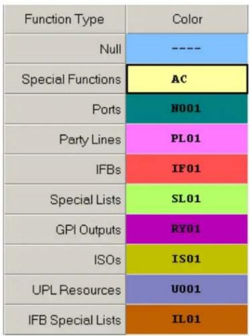
FIGURE 12. Color Grid
Function Type Column
The Function Type column displays the different function types you can make key color changes for.
Available selections are: Null, Special Functions, Ports, Party Lines, IFBs, Special Lists, GPI Outputs, ISOs, UPL Resources, and IFB Special Lists.
NOTE: Only colors assigned to Null, Ports, and IFBs affect the PAP-5032.
Color Column
The Color column displays the current text and background colors assigned to the function type.
NOTE: You must select the current color box next to the function type you want to change the color for. When selected, a thick black line appears around the box.
Only Show Non-Default Background Colors Check Box
The Only Show Non-Default Background Colors check box, if selected, shows colors only for function types set to a color other than their default color.
Key Assignment Page
The Key Assignment page, shown in Figure 13, is used to change the colors assigned to the various assignment types. This means you can assign different colors to the individual function type resources. For example, you can change the display color for the party line assignment number 003.
![AZedit - [Untitled] - Keypanel Colors File Online Authentication Edit View System Alphas Status Options Logging Help RVON Keypanels KPs LCPs PAPs ARPs PLs IFBs IFBs Priorities Lstn Src Lstn Dest IFB SLs Function Types Key Assignments Assignment Groups Miscellaneous Colors Recent Colors Current Color Port / Color 001 N001 002 N002 003 N003 004 N004 005 N005 006 N006 007 N007 008 N008 009 N009 010 N010 011 N011 012 N012 013 N013 Apply to Background Default Background Apply to Text Default Text Only show non-default background colors](/content/2026/05/1062929/images/18cf68c9787bf4693405d34d1140eee8f7ac2ee1172a2aa13bb80613afe8208a.jpg)
FIGURE 13. Key Assignments Page
Select Function Type Drop Down Menu
The Select Function Type drop down menu is used to select the function type you want to display the function number resources for.
Available selections for this field are: Ports, Party Lines, IFBs, Special Lists, GPI Outputs, ISOs, UPL Resources, and IFB Special Lists.
NOTE: Only colors assigned to Null, Ports, and IFBs affect the PAP-5032.
Function Number Column
The Function Number column displays the function numbers (resources available) you can modify the color of the assigned key for.
NOTE: Key colors are associated with assignment types, not the keys they are assigned to.
Color Column
The Color column displays the current color assigned to the function number.
NOTE: You must select the current color box next to the function number you want to change the color for. When selected, a thick black line appears around the box indicating it is selected.
Miscellaneous Colors Page
The Miscellaneous Colors page, shown in Figure 14, is used to change the colors of the talk and listen indicators seen on the KP-Series panel when talk and/or listen is activated.
![AZedit - [Untitled] - Keypanel Colors File Online Authentication Edit View System Alphas Status Options Logging Help RVON Keypanels KPs LCPs PAPs ARPs PLs IFBs IFBs Priorities Lstn Src Lstn Dest IFB SLs Function Types Key Assignments Assignment Groups Miscellaneous Colors Recent Colors Item Color Talk Indicator Listen Indicator Current Color Hue: 80 Red: 0 Sat: 240 Green: 255 Lum: 120 Blue: 0 Apply to Background Default Background Apply to Text Default Text Only show non-default background colors](/content/2026/05/1062929/images/e74c1f0361a0c8ed7c4fd40472d8943b4e91b4efdbf73327733065efc8bb0893.jpg)
FIGURE 14. Miscellaneous Colors Page
Download Firmware to the Panel From AZedit
To download firmware to the panel, do the following:
- Open AZedit.
- From the Status menu, select Software Versions | Keypanels. The Port Status window appears.
- Find the port number where the PAP-5032 is assigned.
![AZedit - [ONLINE] - Keypanel Version Information File Online Authentication Edit View System Alphas Status Options Logging Help](/content/2026/05/1062929/images/64a60c0fd7b59062a1696bff2fa3dd7b9cdab26ea3d77369c095e104b57c0f39.jpg)
| Port / | Alpha | Version | ||
| 010 | N010 | PAP-5032PB, Ver | Info | > A v5.0.0 |
| 011 | N011 | n/a | ||
| 012 | ITAL | n/a | Download firmware... | |
| 013 | N013 | n/a | Download font... | |
| 014 | N014 | n/a | Download splash screen... | |
| 015 | N015 | n/a | Download screen saver... | |
| 016 | N016 | n/a | ||
| 017 | N017 | n/a | Download icons... | |
| 018 | N018 | n/a | Download chime... | |
| 019 | N019 | n/a | Download keypanel configuration... | |
| 020 | N020 | n/a | ||
| 021 | N021 | n/a | Download license... | |
| 022 | N022 | n/a | ||
| 023 | N023 | n/a | ||
- Highlight the Port (panel) to be updated. You may select more than one at a time by holding CTRL key down while you select.
- Right-click the highlighted selections. A popup menu appears.
- Select Download firmware... The Firmware Download window appears.
- Using the browse button, browse to the file to be downloaded.
8. Click Open.
The Download Device Firmware window appears.
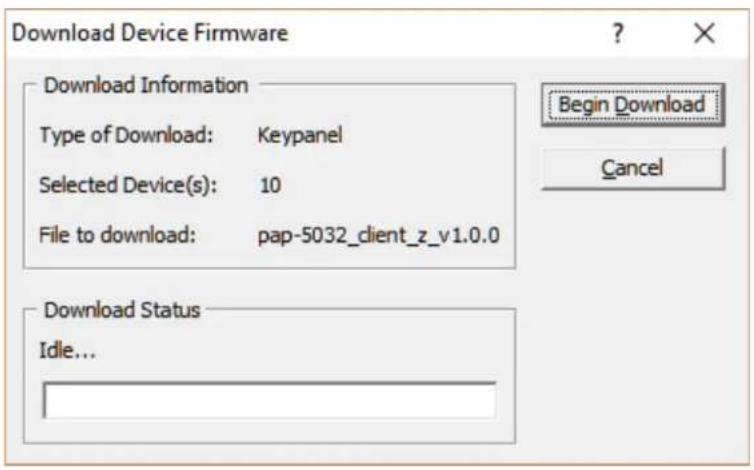
9. Click Begin Download.
The download begins.
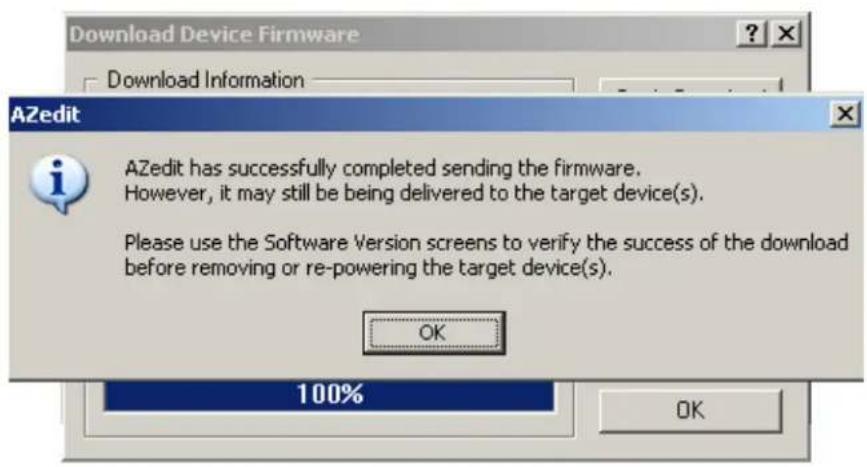
- Verify the panel displays the FIRMWARE DOWNLOAD message with a progression bar.
Once the download is complete, the panel has to process the downloaded file.

- Click OK.
The PAP-5032 firmware download finishes.
- Verify the panel displays the PROCESSING DOWNLOAD message with a progression bar.

NOTE: Processing Download is only shown if the downloaded firmware image is compressed.
- Once the panel is finished processing the download, the panel begins to reprogram.
The panel flashes a REPROGRAMMING DO NOT POWER OFF message in the display panel.

NOTE:
- This can take up to 2 minutes to complete if connected via OMNEO and up to 15 minutes to complete if connected via AIO. Use the Keypanel Version Information window to follow the progress of the download. Also, the panel displays Firmware Download on the panel display until the download is complete.
• The PAP-5032 resets itself once the firmware download is complete and the flash reprogrammed. -
While the firmware is downloading, chunk progress is displayed by incremental blocks. Also, the panel displays an icon warning not to turn off the panel while the flash is being reprogrammed.
-
In the Keypanel Version Information window, verify the version upgrade.
NOTE: To get to the Keypanel Version Information window, select Status|Software Versions|Kepanels.
![AZedit - [ONLINE] - Keypanel Version Information File Online Authentication Edit View System Alphas Status Port / Alpha Version 010 N010 PAP-5032PB, Version 1.0.0 [RSTP], Ma 011 N011 n/a 012 ITAL n/a 013 N013 n/a](/content/2026/05/1062929/images/a201900dab366b8a1b83112ef5014a3872491282343ca3ca462e3aa94f8cebb3.jpg)
Download Firmware to the Panel Using the Firmware Upload Tool
Required Firmware version:
FWUT V5.4.0 or later
To download firmware to the panel, do the following:
- Open the Firmware Upload Tool.
- From the File menu, select Options.
The Firmware Upload Tool Options window appears.
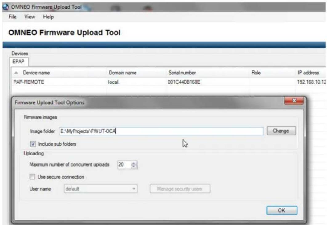
- Click the Change button.
The folder network window appears.
- Navigate to the folder where the firmware resides.
- Click OK.
- Click OK, again.
The Firmware Upload Tool Options window closes.
- From the EPAP Device page, select the device you want to update.
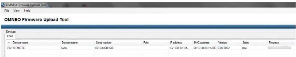
- Click the Upload button.
The Select Firmware for Upload window appears.
- From the list of firmware, select the firmware you want to download.
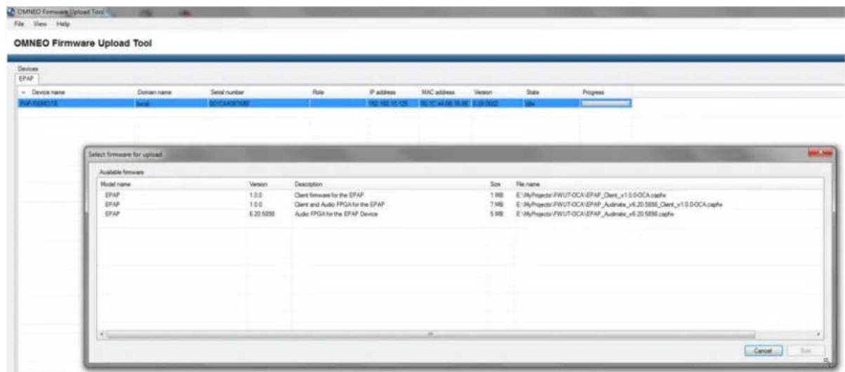
- Click the Start button.
Once the firmware has been updated, the panel reboots automatically.
Enable Downloading New Bootloader from the Panel
The PAP-5032 uses the same boot loader as the KP-Series keypanels, but it requires bootloader v1.4.0 or later. If a bootloader with a version prior to v1.4.0 is downloaded to the PAP-5032, it will not be programmed to flash.
Download Firmware Using the Bootloader
The Bootloader is used to upload a new bootloader image or to upgrade the panel firmware if it is corrupt or fails and makes downloading of new firmware impossible.
If the panel firmware is corrupt, the panel may boot automatically into the bootloader. However, if the panel firmware appears valid, but fails to run properly, you may need to force the panel into the bootloader in order to download the new firmware.
Run the Bootloader
To run the bootloader, do the following:
- Power off the panel.
- Verify the PAP-5032 is powered off, but still connected to the FRAME.
- At the same time, press and hold panel buttons 15 and 16 (the right-most two button of the bottom row), while you connect the power cord to the panel.
PAP-5032 Boot Loader Waiting for download... appears in the panel display.

- In AZedit, from the Status menu, select Software Versions. The Software Versions popup menu appears.
- From the Software Versions popup menu, select Keypanels. The Keypanel Version Information window appears.
| Port / | Alpha | Version |
| 124 | 124 | n/a |
| 125 | 125 | n/a |
| 126 | 126 | n/a |
| 127 | 127 | n/a |
| 128 | 128 | PAP-5032 BOOT LOADER, VERSION 1.2.0, FEB |
| 129 | 129 | KP-32, VERSION 2.0.7 (APR 04 2006) U2=0ABE |
| 130 | 130 | n/a |
| 131 | 131 | n/a |
| 132 | 132 | n/a |
| 133 | 133 | n/a |
| 134 | 134 | n/a |
| 135 | 135 | n/a |
- From the Keypanel Version Information window, find the port number where the keypanel is assigned.
NOTE: Notice the Version column is showing PAP-5032 Bootloader Version 1.2.0 is shown.
- Right-click on the PAP-5032. A popup menu appears.
- From the popup menu, select Download Firmware... The Firmware Download navigation window appears.
- Navigate to and select your firmware file (i.e., PAP-5032_client_z.mot).
- Click Open. The Download Device Firmware window appears.
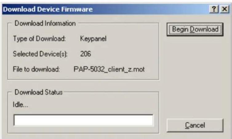
- Click Begin Download. The Download begins and a popup message appears.
- Click OK. The PAP-5032 firmware download finishes.
NOTE: This can take up to 15 minutes to complete if connected via AIO. Use the Keypanel Version Information window to follow the progress of the download (the number and percentage of chunks completed). Also, the firmware progression is displayed on the panel display until the download is complete.
NOTE: Once the Boot Loader is finished downloading, it reboots itself and reprograms the flash.

Display the FPGA Version on the Panel
To display the FPGA version currently installed in the panel, do the following:
- While pressing the Main Vol and Aux Vol encoders on the front of the panel at the same time, press the MENU button. The main menu appears in the panel display.
- Using the left and right arrow buttons, select Service.
- Press the SEL button.
The Service menu options appear in the panel display.
- Using the left and right arrow buttons, select FPGA Version.
- Press the SEL button.
Version X.X.X (where X represents the FPGA version numbers) appears in the panel display.
Download and Upgrade the FPGA to the PAP-5032
There are four (4) phases to upgrading the FPGA on a panel:
- Downloading the FPGA firmware to the matrix
- Downloading the FPGA firmware to the panel
- Processing the download
• Reprogramming the panel
To download the FPGA to the panel, do the following:
- Open AZedit.
- From the Status menu, select Software Versions|Keypanels. The Keypanel Version Information window appears.
- Find the port number where the PAP-5032 is assigned.
- Highlight the Port (panel) to be updated. You may select more than one at a time by holding CTRL key down while you select.
- Right-click the highlighted selections. A popup menu appears.
- Select Download Firmware. The Firmware Download window appears.
- Using the browse button, navigate to the FPGA file you want to use.
8. Click Open.
The Download Device Firmware window appears.
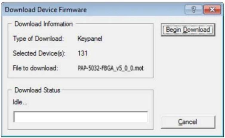
9. Click Begin Download.
The download begins. A progress bar appears to show the progress of the download.
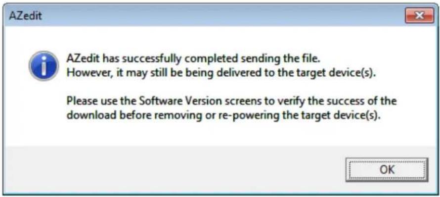
10. Click OK.
The PAP-5032 firmware download to the Matrix finishes. The Download FPGA Firmware To The Panel begins.
- Verify the Keypanel Version Information window is displaying the numbers of chunks (of data) transferred to the panel.
| Port / | Alpha | Version |
| 112 | N112 | n/a |
| 113 | N113 | n/a |
| 114 | N114 | n/a |
| 115 | N115 | n/a |
| 116 | N116 | n/a |
| 117 | N117 | n/a |
| 118 | N118 | n/a |
| 119 | N119 | n/a |
| 120 | N120 | n/a |
| 121 | N121 | n/a |
| 122 | N122 | n/a |
| 123 | N123 | n/a |
| 124 | N124 | n/a |
| 125 | N125 | n/a |
| 126 | N126 | n/a |
| 127 | N127 | n/a |
| 128 | N128 | n/a |
| 129 | N129 | n/a |
| 130 | N130 | n/a |
| 131 | N131 | Download: Chunk 15 of 72, try 1, 34% |
| 132 | N132 | n/a |
| 133 | N133 | n/a |
| 134 | N134 | n/a |
| 135 | N135 | n/a |
- Verify the panel displays the FPGA DOWNLOAD message with a progression bar. Once the download is complete, the panel has to process the downloaded file.

- Verify the Keypanel Version Information window displays Processing download on the panel port you chose.
![AZedit - [ONLINE] - Keypanel Version Information File Online Authentication Edit View System Alphas Status Option Port Alpha Version 118 N118 n/a 119 N119 n/a 120 N120 n/a 121 N121 n/a 122 N122 n/a 123 N123 n/a 124 N124 n/a 125 N125 n/a 126 N126 n/a 127 N127 n/a 128 N128 n/a 129 N129 n/a 130 N130 n/a 131 N131 Processing download 132 N132 n/a 133 N133 n/a](/content/2026/05/1062929/images/c1540cf5f579412f954962002459e34a557a6b0ded7ad2671aa0f0d616601996.jpg)
- Verify the panel displays PROCESSING DOWNLOAD with a progression bar.

Once the panel is finished processing the download, the panel begins to reprogram. The panel flashes a REPROGRAMMING: DO NOT POWER OFF message in the display panel. This can take several minutes.

Once the reprogramming is complete, the panel reboots.
Download a Splash Screen
IMPORTANT:
The maximum bitmap size is 576 x 90. If the bitmap is smaller than the full screen dimensions, the panel centers the bitmap horizontally and vertically on the display and fills the background with the same color as the pixel in the top left corner of the splash screen.
- Open AZedit.
- From the Status menu, select Software Versions|Keypanels. The Keypanel Version Information window appears.
- Find the port number where the PAP-5032 is assigned.
- Highlight the Port (panel) to be updated. You may select more than one at a time by holding CTRL key down while you select.
- Right-click the highlighted selections. A popup menu appears.
- Select Download splash screen.... The Splash Screen Download window appears.
- Click Open. The Download Splash Screen File window appears.
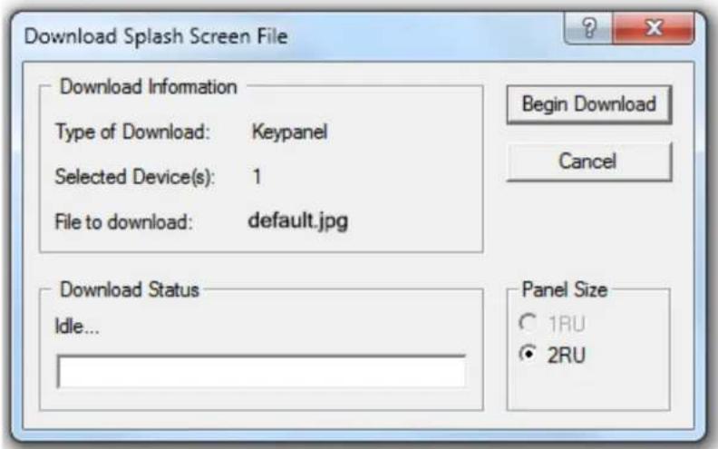
- In the Panel Size group box, select 2RU.
-
Click Begin Download. The download begins. A progress bar appears to show the progress of the download. Once the download is complete the Download Splash Screen File window closes.
-
Verify the Keypanel Version Information window is displaying the numbers of chunks (of data) transferred to the panel.
![AZedit - [ONLINE] - Keypanel Version Information File Online Authentication Edit View System Alphas Status Options Logging Help KPs PLs IFBs IFB SLs SLs RYs ISOs GPIs UPL URs AGRPs ADs XPTs RV PAT New Open Merge Save Save As Partial Print Port / Alpha Version 001 N001 n/a 002 N002 Download: Chunk 9 of 15 try 1, 63% 003 N003 n/a 004 N004 n/a 005 N005 n/a 006 N006 n/a 007 N007 n/a 008 N008 n/a](/content/2026/05/1062929/images/d11d87f63db69ec4b52f5b0c4b4d46608896b47d6a1e46286ad98318751bd00e.jpg)
- Verify the panel displays the SPLASH DOWNLOAD message with a progression bar.
Once the download is complete, the panel has to process the downloaded file.

Once the panel is finished processing the download, the panel begins to reprogram. The panel flashes a REPROGRAMMING: DO NOT POWER OFF message in the display panel. This can take several minutes.

Once the reprogramming is complete, the panel reboots.
Download a Font File
- Open AZedit.
- From the Status menu, select Software Versions|Keypanels. The Keypanel Version Information window appears.
- Find the port number where the PAP-5032 is assigned.
- Highlight the Port (panel) to be updated. You may select more than one at a time by holding CTRL key down while you select.
- Right-click the highlighted selections. A popup menu appears.
- Select Download font.... The Font Download window appears.
- Navigate to the font file (.kpf) you want to use.
- Click Open. The Download Keypanel Font window appears.
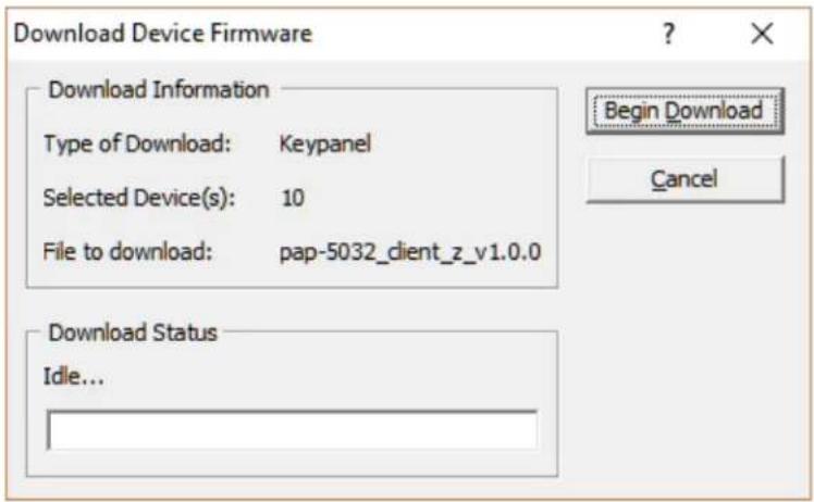
- Click Begin Download.
The download begins. A progress bar appears to show the progress of the download.
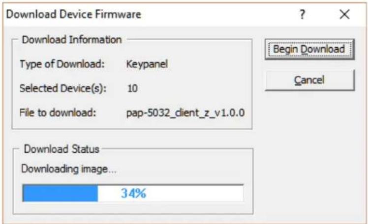
Once the download is complete the Download Keypanel Font window closes.
- Verify the Keypanel Version Information window is displaying the numbers of chunks (of data) transferred to the panel.
![AZedit - [ONLINE] - Keypanel Version Information File Online Authentication Edit View System Alphas Status Options Logging Help KPs PLs IFBs IFB SLs SLs RYs ISOs GPIs UPL URs AGRPs ADs XPTs RV PAT New Open Merge Save Save As Partial Print](/content/2026/05/1062929/images/531507799b0647fb7ea35398f50922f0418d011ac37760ef665b3d62a87c8bb4.jpg)
- Verify the panel displays the FONT DOWNLOAD message with a progression bar.
Once the download is complete, the panel has to process the downloaded file.

- Verify the Keypanel Version Information window displays Processing download on the panel port you chose.
| Port / | Alpha | Version |
| 118 | N118 | n/a |
| 119 | N119 | n/a |
| 120 | N120 | n/a |
| 121 | N121 | n/a |
| 122 | N122 | n/a |
| 123 | N123 | n/a |
| 124 | N124 | n/a |
| 125 | N125 | n/a |
| 126 | N126 | n/a |
| 127 | N127 | n/a |
| 128 | N128 | n/a |
| 129 | N129 | n/a |
| 130 | N130 | n/a |
| 131 | N131 | Processing download |
| 132 | N132 | n/a |
| 133 | N133 | n/a |
| 134 | N134 | n/a |
- Verify the panel displays the PROCESSING DOWNLOAD message with a progression bar.

Once the panel is finished processing the download, the panel begins to reprogram. The panel flashes a Reprogramming: Do Not Power Off message in the display panel. This can take several minutes.

Once the reprogramming is complete, the panel reboots.
Download an Icon File
IMPORTANT: The following instructions can be used for either panel icons or tally (key overlay) icons.
To download an icon file, do the following:
- Open AZedit.
- From the Status menu, select Software Versions|Keypanels. The Keypanel Version Information window appears.
- Find and select the Port (panel) to be updated. You may select more than one at a time by holding the CRTL key down while you select.
- Right-click the highlighted selection. A popup menu appears.
![AZedit - [ONLINE] - Keypanel Version Information File Online Authentication Edit View System Alphas Status Options Logging Help Port Alpha Version / 001 N001 K8 5022 Version 1 03, Sep 4 2015, CRC=1a 003 N00 002 N00 004 N00 005 5 006 6 n/a 007 7 n/a Info Download firmware... Download font... Download splash screen... Download icons...](/content/2026/05/1062929/images/836c900491a0ad3376baeef84888bf113ae29b14f42fc2a568688cfbb2d12fd4.jpg)
- Select Download icons.... The Icon Download window appears.
- Navigate to the icon file (.bmp or .jpg) you want to use.
7. Click Open.
The Download Icon File window appears.
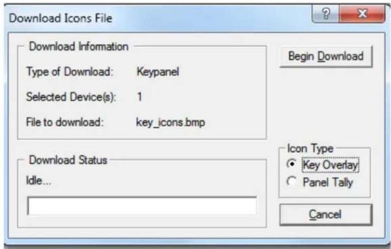
- Verify the correct Icon Type radio button is selected – Key Overlay or Panel Tally radio button.
9. Click Begin Download.
The download begins. A progress bar appears showing the progress of the download. Once the download is complete the Download Keypanel Font window closes.
- Verify the Keypanel Version Information window displays the numbers of chunks (of data) transferred to the panel.
![AZedit - [ONLINE] - Keypanel Version Information File Online Authentication Edit View System Alphas Status Options Logging Help Port Alpha Version / 001 N001 Download: Chunk 6 of 9, try 1, 41% 003 N003 Unknown 002 N002 n/a 004 N004 n/a 005 5 n/a](/content/2026/05/1062929/images/0d40c2c81f8e6ee7482dfefe53a09a5c5542c223f08ff1ead3b86e9b87acd245.jpg)
- Verify the panel displays the ICON DOWNLOAD message with a progression bar.

Once the panel is finished, it begins to reprogram. The panel flashes a REPROGRAMMING: DO NOT POWER OFF message in the display panel. This can take several minutes.

Once the reprogramming is complete, the panel reboots.
NOTE: A menu system quick reference chart is located at "Panel Menu Quick Reference" on page 113.
Main Menu Access
IMPORTANT: For more detailed information on Basic Key operation, see “Menu Navigation and Shaft Encoder Knobs” on page 44.
The Main Menu is the top-most level of the menu structure.
Available selections for this menu are:
Audio Options
Display
Key Assign
Key Options
OMNEO Offers (present when the panel is running OMNEO firmware or if there is an OEI-2 connected to the AIO port)
RVON Offers (present when the panel is running RVON firmware or if there is an RVON-IO connected to the AIO port)
Save Config
Service
To access the main menu structure, do the following:
- On the keypad, press the MENU button.
The Information menu structure displays across the middle of the panel display.

- Using the arrow buttons on the keypad, navigate through the menu options.
- Press the SEL button.
The submenu for the selection appears.
Menu System, Audio Options
Available options for this menu are:
Advanced
Ganged Vols
Headset Spkr
Inputs
Max Volume
Min Volume
Reference Level
Speaker
Audio Options Menu, Advanced
- Filters
- Gating
- Metering
- Mixing
- Mix Mode
Filters
Filters allow you to add a bandpass filter, a preset frequency response (equalization) filter or a notch filter to the Matrix In audio source.
Bandpass
The Bandpass menu is used to enable using bandpass filters as well as set a low and high frequency range where frequencies within the two frequency points are passed and anything outside of the range is rejected.
To configure a bandpass range for Inputs, do the following:
- Starting at the Audio Options|Advanced|Filters menu, select Bandpass.
- Press the SEL button.
Inputs and Outputs appears in the panel display.
- Using the arrow buttons, select Input.
- Press the SEL button.
Aux 1, Aux 2, OMNEO 1, and OMNEO 2 appear in the panel display.
- Using the arrow buttons, select either Aux 1, Aux 2, OMNEO 1 or OMNEO 2.
- Press the SEL button.
Frequencies and Mode appear in the panel display.
- Using the arrow buttons, select Mode.
Disabled and Enabled appear in the panel display. - Using the arrow buttons, select Enabled.
- Press the SEL button.
An arrow appears next to the selected option.
- Press the CLR button.
Frequencies and Mode appear in the panel display.
- Using the arrow buttons, select Frequencies.
- Press the SEL button.
The Low Freq scroll box and the High Freq scroll box appear in the panel display.
- Using the up and down arrow buttons, select the low frequency you desire.
- Using the left and right arrow buttons, select the high frequency scroll box.
- Using the up and down arrow buttons, select the high frequency you desire.
To configure a bandpass range for Outputs, do the following:
- Starting at the Audio Options|Advanced|Filters menu, select Bandpass.
Inputs and Outputs appears in the panel display. - Using the arrow buttons, select Output.
- Press the SEL button.
Front Hdst and Rear Hdst appear in the panel display.
- Using the arrow buttons, select the output you desire to modify.
If Front Hdst or Rear Hdst is chosen:
a. Press the SEL button.
Both, Left Chan, and Right Chan appear in the panel display.
b. Using the left and right arrow buttons, select either Both, Left Chan, or Right Chan.
- Press the SEL button.
Frequencies and Mode appear in the panel display.
- Using the arrow buttons, select Mode.
Disabled and Enabled appear in the panel display.
-
Using the arrow buttons, select Enabled.
-
Press the SEL button.
An arrow appears next to the selected option.
- Press the CLR button.
Frequencies and Mode appear in the panel display.
-
Using the left and right arrow buttons, select Frequencies.
-
Press the SEL button.
The Low Freq scroll box and the High Freq scroll box appear in the panel display.
-
Using the up and down arrow buttons, select the low frequency you desire.
-
Using the left and right arrow buttons, select the high frequency scroll box.
-
Using the up and down arrow buttons, select the high frequency you desire.
Equalization
Equalization allows the user to select predefined settings that modify the frequency envelope of an audio channel. This is a 5-band equalizer. Each preset provides a different EQ to be applied to the audio.
Available selections for this menu are:
Default 0 dB (15Hz–20kHz)
Hiss Reduction 0 dB (15Hz–2kHz)
-6 dB (2kHz–12.6kHz)
Rumble Reduction 0 dB (50Hz–20kHz)
Noise Reduction 0 dB (50Hz–2kHz)
-6 dB (2kHz–8kHz)
-80dB (8kHz–12.6kHz)
To configure a preset frequency response for an input, do the following:
- Starting at the Audio Options|Advanced|Filters menu, select Equalization.
Inputs and Outputs appears in the panel display.
-
Using the arrow buttons, select Input.
-
Press the SEL button.
Matrix In appears in the panel display.
-
Select Matrix In.
-
Press the SEL button.
Mode and Presets appear in the panel display.
- Using the arrow buttons, select Mode.
Disabled and Enabled appear in the panel display.
-
Using the arrow buttons, select Enabled.
-
Press the SEL button.
An arrow appears next to the selected option.
- Press the CLR button.
Mode and Presets appear in the panel display.
-
Using the arrow buttons, select Presets.
-
Press the SEL button.
Default, Hiss Reduction, Rumble Reduction, and Noise Reduction appear in the panel display.
-
Using the arrow buttons, select Default, Hiss Reduction, Rumble Reduction, or Noise Reduction.
-
Press the SEL button.
An arrow appears next to preset selected.
To configure a preset frequency response for an output, do the following:
- Starting at the Audio Options|Advanced|Filters menu, select Equalization. Inputs and Outputs appears in the panel display.
- Using the arrow buttons, select either Output.
- Press the SEL button. Front Spkr and Rear Spkr appear in the panel display.
- Using the arrow buttons, select either Front Spkr or Rear Spkr.
- Press the SEL button. Mode and Presets appear in the panel display.
- Using the arrow buttons, select Mode. Disabled and Enabled appear in the panel display.
- Using the arrow buttons, select Enabled.
- Press the SEL button. An arrow appears next to the selected option.
- Press the CLR button. Mode and Presets appear in the panel display.
- Using the arrow buttons, select Presets.
- Press the SEL button. Default, Hiss Reduction, and Rumble Reduction appear in the panel display.
- Using the arrow buttons, select Default, Hiss Reduction, Rumble Reduction, or Noise Reduction.
- Press the SEL button. An arrow appears next to preset selected.
Notch
The Notch menu allows you to add a notch filter to the Matrix In source. This can be useful when the panel data port signal is being heard in the audio line due to cable routing problems.
By default, the notch filter is set to Disabled.
Available options for this menu are:
Disabled
Narrow 9500hz–9700Hz (200Hz band)
Default 9450hz–9750Hz (300Hz band)
Wide 9400hz–9800Hz (400Hz band)
Gating
Gating (also called VOX) allows you to minimize or eliminate background noise problems by shutting off an audio source when the audio level drops below a certain threshold.
Gating can be applied to the following:
Aux 1
Aux 2
Matrix In
OMNEO 2
The range for the gating threshold is -17dB to +18dB, and Disabled.
By default, the gating threshold is set to Disabled.
Nominal inputs are as follows:
Aux 1-2 8dBu
Matrix In 8dBu
OMNEO 1-2 8dBu
To configure gating on the program assign panel, do the following:
-
Starting at the Audio Options|Advanced menu, select Gating.
-
Press the SEL button.
Aux 1, Aux 2, Matrix In, OMNEO 1, and OMNEO 2 appear in the panel display.
-
Using the left or right arrow buttons, select Aux 1, Aux 2, Matrix In, OMNEO 1, or OMNEO 2.
-
Press the SEL button.
The Threshold scroll menu appears.
-
Using the up and down arrow buttons, select the threshold you desire.
-
Press BACK to go to the previous menu item OR
Press and hold CLR to exit the menu structure.
Metering
Metering allows you to monitor an audio source connected to the program assign panel. The energy of the incoming audio is split into five bands and shown on the left side of the panel display when enabled.
The decibels display range is from 28dB below nominal to 8dB above nominal
The bands are defined as:
Band 1 100 Hz to 400 Hz
Band 2 400 Hz to 800 Hz
Band 3 800 Hz to 1.6 kHz
Band 4 1.6 kHz to 3.2 kHz
Band 5 3.2 kHz to 15 kHz
NOTE: Only one channel can be metered at a time.
You can enable metering on:
Aux1
Aux2
Matrix In
None (default)
OMNEO 1
OMNEO 2
To enable metering, do the following:
- Starting at the Audio Options|Advanced menu, select Metering.
- Press the SEL button.
Aux 1, Aux 2, Matrix In, None, OMNEO 1, and OMNEO 2 appear in the panel display.
-
Using the arrow key, select Aux 1, Aux 2, Matrix In, None, OMNEO 1, or OMNEO 2.
-
Press the SEL button.
An arrow appears next to the selected option.
Mixing
Mixing allows you to route selected audio signals to the following destinations:
- Front Left Headphone
- Rear Speaker
- Front Right Headphone
- Rear Left Headphone
- Front Speaker
- Rear Right Headphone
- Line Out
IMPORTANT:
If OMNEO is enabled, OMNEO 1 is not available because it is acting as the Matrix. On the other hand, if AIO is enabled, OMNEO 1 and OMNEO 2 are both available as auxiliary channels.
By default, the microphone signals are routed to the matrix. The matrix signal is routed to the front speaker and to the left and right channels of the front headphones. These defaults can be changed via the Audio Options sub-menus for Panel Mic, Headset Mic, Speaker, and Headset Speaker.
Available options for this menu are:
Front Hdst
Front Spkr
Line Out
Rear Hdst
Rear Spkr.
TABLE 2. Resources Table
| Source Destination | Matrix Audio In | Aux 1 | Aux 2 | OMNEO 1 | OMNEO 2 |
| Front Speakers | a | X | X | X | X |
| Front Headset Left | a | X | X | X | X |
| Front Headset Right | a | X | X | X | X |
| Rear Headset Left | a | X | X | X | X |
| Rear Speaker Left | a | X | X | X | X |
| Rear Speaker Right | a | X | X | X | X |
| LINE OUT X X X | X | X |
a. The Matrix input cannot be mixed to speaker or headset outputs using this menu. To mix Matrix In to speakers or headsets, use the Speaker and Headset Spkr menus.
To configure mixing, do the following:
- Starting at the Audio Options|Advanced menu, select Mixing.
- Press the SEL button.
Front Hdst, Front Spkr, Line Out, Rear Hdst, and Rear Spkr appear in the panel display.
- Using the left or right arrow buttons, select a the destination to mix to (or the destination to which the sources will be mixed).
NOTE: If Front Hdst or Rear Hdst is chosen, an additional step of choosing Both, Left Chan, or Right Chan is required.
- Press the SEL button.
If Front Spkr or Rear Spkr is selected Aux 1, Aux 2, OMNEO 1, and OMNEO 2 appears in the panel display.
- Using the left or right arrow buttons, select the input to mix to the selected output.
- Press the SEL button.
An arrow appears next to the selection.
NOTE: Repeat steps 5 and 6 to select additional inputs to mix to the selected output.
Mix Mode
The Mix Mode menu is used to control whether mixes made to the speakers and headsets are muted when they are not active.
Available options for this menu are:
Aux Mixes Switched (default)
Aux inputs mixed to line out, speakers or headsets are only heard when the panel is in the appropriate headset or speaker mode.
Mixes always active
Aux inputs mixed to speakers or headset are always heard, regardless of whether the panel is in headset or speaker mode.
To configure Mix Mode, do the following:
- Starting at the Audio Options|Advanced menu, select Mix Mode.
- Press the SEL button.
Aux Mixes Switched and Mixes Always Active appear in the panel display.
- Using the left or right arrow buttons, select the mix mode you desire.
- Press the SEL button.
An arrow appears next to the selection.
Audio Options Menu, Ganged Vols
Ganged Vols is used to set what happens when adjusting the volume for a ganged channel pair when the volumes are not identical and one of the volumes reaches the minimum or maximum level.
Available options:
Disappearing Mode
Allows adjustments to continue when one of the volumes of the ganged pair hits a limit. This setting adjusts the volume difference until the difference or offset between the volumes disappears.
Fixed Offset Mode
Prevents adjustments to continue when one of the volumes of the ganged pair hits a limit. This setting maintains the difference between the two volumes.
To configure ganged volume, do the following:
-
Starting at Audio Options, select Ganged Vols.
-
Press the SEL button.
Disappearing and Fixed Offset appear in the panel display.
-
Using the left or right arrow buttons, select either Disappearing or Fixed Offset.
-
Press the SEL button.
An arrow appears next to the selected option.
Audio Options Menu, Headset Speaker
The Headset Spkr menu option is used to control the headset detection functions: auto-transfer, which is used to detect if a headset is present, and mode, which determines when and where audio is heard. Also from this menu, the Main shaft encoder is defined how to control the front and rear speakers.
Volume Control
Available selections for the Volume Control menu are:
Ganged
The volume controls are tied to each other, only one knob is turned to adjust volume levels. The volume of both front and rear headset speakers are controlled together.
Individual The volume controls are separate to each other.
NOTE: If you gang speakers and/or headset volumes, you may see a split volume bar if the front and rear have different volumes with ganging is enabled. The front speaker or headset is the top portion of the bar, while the bottom portion of the bar is the rear speaker or headset volume.
To define how the Main Volume shaft encoder controls the volume for the front and rear channels, do the following:
-
Starting at the Audio Options|Headset Spkr menu, select Volume Control.
-
Press the SEL button.
Ganged and Individual appear in the panel display.
-
Using the left or right arrow buttons, select Ganged or Individual.
-
Press the SEL button.
An arrow appears next to the selected option.
Auto-Transfer
Available selections for the Auto-transfer menu are:
Disabled
Enabled
When enabled, the PAP-5032 automatically enters or leaves headset mode when a headset is plugged in or removed.
To configure the Headset Auto-Transfer function, do the following:
- Starting at the Audio Options|Headset Spkr menu, select Front or Rear.
- Press the SEL button.
Auto-Transfer and Mode appear in the panel display. - Using the left or right arrow buttons, select Auto-Transfer.
- Press the SEL button.
Disabled and Enabled appear in the panel display. - Using the left or right arrow buttons, select Disabled or Enabled.
- Press the SEL button.
An arrow appears next to the selected option.
Mode
Available selections for the Mode menu are:
Always On (d)
Disabled
Switched
When set to Switched, the state of the Headset Spkr is controlled by the HDST Sel key.
To configure the Headset Spkr Mode, do the following:
- Starting at the Audio Options|Headset Spkr menu, select Front or Rear.
- Press the SEL button.
Auto-Transfer and Mode appear in the panel display. - Using the left or right arrow buttons, select Mode.
- Press the SEL button.
Both, Left Chan, and Right Chan appear in the panel display. - Using the left or right arrow buttons, select the mode you want.
- Press the SEL button.
Always On, Disabled, and Switched appear in the panel display. - Using the left or right arrow buttons, select the mode.
- Press the SEL button.
An arrow appears next to the selected option.
Audio Options Menu, Inputs
The Inputs menu is used to enable or disable volume control for audio inputs through the front panel encoder. The PAP-5032 has five Input connectors on the back panel of the unit. By default, all inputs are enabled. This means the inputs are visible as inputs in the Mixing menu and (if mixed somewhere) can be selected for volume control.
If disabled, the inputs are not visible in the mixing menu and cannot be selected for volume control.
NOTE: Disabling an input does not undo any of the mixes you had previously established in the Mixing menu; however, it hides access to volume control of this input. This is useful if you want to set the matrix input volume, and then want to disable the volume control so users cannot adjust the Matrix volume.
To enable or disable an input, do the following:
- Starting at the Audio Options|Inputs menu, select Aux 1, Aux 2, Matrix In, or OMNEO2.
- Press the SEL button. Disabled and Enabled appear in the panel display.
- Using the arrow buttons, select Enabled to enable the selected Input. OR Using the arrow buttons, select Disabled to disable the selected Input.
Audio Options Menu, Max Volume
The Max Volume menu is used to set the maximum level, in dB, of the volume the user can configure for a headset or a speaker. This feature prevents incoming audio from being too loud.
The range for this field is Mute, -48dB to +10 dB for speakers; Mute -48 dB to +24 dB for headsets. The default setting is 10dB.
To set the maximum volume for headsets or speakers, do the following:
- Starting at the Audio Options|Max Volume menu, select Headset or Speaker.
- Press the SEL button. Front and Rear appear in the panel display.
- Using the left or right arrow buttons, select Front or Rear.
- Press the SEL button. The Max Volume: scroll box appears in the panel display.
- Using the up and down arrow buttons, scroll to the maximum volume desired.
Audio Options Menu, Min Volume
The Min Volume menu item is used to set the minimum volume level, in dB, for different sources on the panel. This is the minimum volume level available when using the Main Volume and Aux Volume control knob, located on the front of the panel.
Available sources are: Headset, Speaker, Aux 1, Aux 2, Matrix In, and OMNEO 2.
The range for this field is -48dB to 10dB, and Mute (except headsets that have an upper limit of +24 dB). By default, this field is set to -6dB for Matrix In, all other options are set to Mute.
To set the min volume, do the following,
- Starting at the Audio Options|Min Volume menu, select the desired source.
- Press the SEL button. The Min Volume: scroll box appears in the panel display.
NOTE: When Headset or Speaker is selected, you must designate the front or rear headset or speaker.
- Using the up and down arrow buttons, scroll to the minimum volume desired.
Audio Options Menu, Reference Level
The Reference Level menu item is used to set the reference audio level for audio received from the matrix
The range for this field is 0dB to +8dB.
The default setting is 0dB.
To set the reference level for audio from the matrix, do the following:
- Starting at the Audio Options menu, select Ref Level.
- Press the SEL button.
The Reference Level: scroll box appears in the panel display. - Using the up and down arrow buttons, scroll to the desired level.
Audio Options Menu, Speaker
The Speaker menu option is used to configure how the speaker operates. Also from this menu the Main Volume shaft encoder is defined how to control the front and rear speakers.
Available selections are:
Always On
Disabled
Switched
When set to Switched, the state of the speaker is controlled by the HDST Sel key.
To configure the speaker, do the following:
- Starting at the Audio Options|Speaker menu, select Front or Rear.
- Press the SEL button.
Always On, Disabled and Switched appear in the panel display. - Using the left or right arrow buttons, select the desired mode.
- Press the SEL button.
An arrow appears next to the selected option.
Volume Control
Available selections for the Volume Control menu are:
NOTE: For more information on Ganged Volume configuration, see “Audio Options Menu, Ganged Vols” on page 85.
Ganged
The volume controls are tied to each other, only one knob is turned to adjust volume levels. The volume of both front and rear headset speakers are controlled together.
Individual The volume controls are independent of each other.
To define how the Main shaft encoder controls the volume for the front and rear channels, do the following:
- Starting at the Audio Options|Speaker menu, select Volume Control.
- Press the SEL button.
Ganged and Individual appear in the panel display. - Using the left or right arrow buttons, select either Ganged or Individual.
- Press the SEL button.
An arrow appears next to the selected option.
Menu System, Display
Use this menu to display information about the panel configuration.
The information available for display is as follows:
MAC Address
Panel ID
(Firmware) Version
Display Menu, MAC Address
MAC Address displays the MAC Address of the panel.
To display the MAC Address, do the following:
-
Starting at the Display menu, select MAC Address.
-
Press the SEL button.
The MAC Address for the panel appears.
Display Menu, Panel ID
Panel ID displays the port number to which the panel is connected.
NOTE: When the panel is not scroll enabled, the Panel ID displays only the port number in the panel display. When the panel is scroll enabled, the port number and port alpha are displayed.
To display the panel ID, do the following:
-
Starting at the Display menu, select Panel ID.
-
Press the SEL button.
The Panel ID display appears showing the port number and alpha (if applicable) for the panel.
Display Menu, Version
Version displays the firmware version currently running on the panel.
NOTE: For firmware upgrades, contact customer service. The panel firmware can be upgraded through AZedit.
To display the firmware version currently loaded on the panel, do the following:
-
Starting at the Display menu, select Version.
-
Press the SEL button.
The Version display appears showing firmware version for the panel.
Menu System, Key Assign Menu
The Key Assign menu is used to assign intercom key assignments and auto functions to panel keys.
Available options for this menu are:
Program Source (P2P)
IFB
To access the key assign menu options, do the following:
- Starting at the Key Assign menu, select the key assignment type you want to assign.
- Press the SEL button.
A scroll list of available assignments appears.
Key Assign Menu, Program Source (P2P)
PGM Source (P2P) assigns a program source to a key. Program sources can only be assigned to the Program Source side of the front panel.
To assign an Program Source to the panel key, do the following:
- Starting at the KeyAssign|PGM Source (P2P) menu, select the Program Source you want to assign to the panel key.
- Press the SEL button.
Tap Key appears in the panel display. - Press down on the panel key position where you want the Program Source assignment to appear.
The key color changes and the alpha appears on the key.
Key Assign Menu, IFB
IFB assigns the IFB assignment type to a key. By default, all IFBs are restricted. You must select the appropriate scroll enable check box in AZedit, to see IFBs.
To assign an IFB to the panel key, do the following:
- Starting at the KeyAssign|IFB menu, select the IFB assignment you want to assign to the panel key.
- Press the SEL button.
Tap Key appears in the panel display.
Press down on the panel key position where you want the IFB assignment to appear.
The key color changes and the alpha appears on the key.
Menu System, Key Options Menu
The Key Options Menu is used to configure many of the panel operation options, such as auto dial functions, chime keys and duration, exclusive keys, key group assignments, solo key configuration, latching options, button lock, and tally operation.
Available options for this menu are:
Change PGM Input Gain
Change IFB Output Gain
Listen Mode
Panel Swap
Key Options Menu, Change PGM Input Gain
The Change PGM Input Gain menu is used to enable or disable the ability to make changes to the input gain of ports used as program sources.
Key Options Menu, Change IFB Output Gain
The Change IFB Output Gain menu is used to enable or disable the ability to make changes to the output gain of ports assigned as the output port for an IFB
Key Options Menu, Listen Mode
The Listen Mode menu is used to select what operating mode the PAP-5032 operates; One or Many.
Available options for this menu are:
One Mode Only one listen key may be active at a time.
Many Mode Many listen keys may be active at the same time.
Key Options Menu, Panel Swap
Panel Swap gives users the ability to quickly and easily change a group of panel assignments on the panel. This is done through the use of virtual expansion panels. Panel swap differs from changing setup pages because the keys can stay active even when they are no longer visible on the main panel. Also, panel swap allows the user a 1-touch trigger to complete two actions at once.
| IMPORTANT: | The PAP-5032 supports up to six expansion panels on any intercom with PAP-5032 support. The expansion panels can be any mix of physical panels (EKP-4016PB) or virtual panels. |
Panel swap can be activated by (or triggered by) a UPG key, a GPI Input, or GPI Output allowing local or remote access. A GPI board does not need to be installed to be controlled by GPI Outputs. However you must set up a Setup Page in AZedit for the virtual EKP to be able to assign key assignments.
Panel Swap Control Options
There are five ways to activate panel swap:
Keypad FWD
Keypad BACK
Keypad UPG1 to UPG 7
GPI Inputs Opto 1 and Opto 2
GPI Outputs Relay 1 and 2
Navigation Mode for Panel Swap
Once you have selected the control trigger, select what panel swap action is performed:
Cycle To Cycle to the Next or Previous panel.
Switch To Switch to a specific panel (for example, MAIN, EKP1, EKP2, etc.
The following icon appears briefly when the Main page is showing
The following icon appears when the first virtual EKP is showing a subsequent virtual EKPs display their number in the icon.
Toggle To Toggle between MAIN and a specific virtual EKP.
Unassigned Used to erase the panel swap action from a trigger or control mechanism.
Panel Swap Key States
Key States define what happens to the key states when a row of keys is not currently visible. There are two possible modes of operation:
Force Off Listen key states are forced off when the row of keys is not visible.
Retain Listen key states are retained when the row of keys is not visible.
When retain is selected and active listen keys are not visible, the following icon shows in the panel display.

In the menu structure, under Panel Swap, the menu items Control and Key States appear, but are unavailable on the panel until one or more virtual EKPs are enabled.
To enable virtual panels, do the following:
- Starting at the Key Options|Panel Swap menu, select Virtual EKPs.
- Press the SEL button.
None, 1 EKP, 2 EKPs, etc appear in the panel display.
- Using the arrow buttons, select the maximum number of virtual EKPs to enable.
- Press the SEL button.
An arrow appears next to the selected option.
To configure how to access the virtual EKPs from the front of the panel, do the following:
- Starting at the Key Options|Panel Swap menu, select Control.
- Press the SEL button.
GPI Inputs, GPI Outputs, and Keypad appear in the panel display.
- Using the arrow buttons, select the control mechanism desired.
- Press the SEL button.
The appropriate sub-control mechanism appears (see “Panel Swap Control Options” on page 91).
- Using the arrow buttons, select the sub-control mechanism.
- Press the SEL button.
Cycle To, Switch To, Toggle To, and Unassigned appear in the panel display.
- Using the arrow buttons, select the navigation mode desired.
- Press the SEL button.
A list of actions for the panel action appears in the panel display (see “Panel Swap Key States” on page 92).
- Using the arrow buttons, select the action desired.
- Press the SEL button.
An arrow appears next to the selected option.
To configure the panel swap key states, do the following:
- Starting at the Key Options|Panel Swap menu, select Key States.
- Press the SEL button. Force Off and Retain appear in the panel display.
- Using the arrow buttons, select the key state you want to enable (see "Panel Swap Key States" on page 92).
- Press the SEL button. An arrow appears next to the selected option.
To erase any programming from the panel swap configuration, do the following:
- Starting at the Key Options|Panel Swap menu, select Control.
- Press the SEL button. GPI Inputs, GPI Outputs, and Keypad appear in the panel display.
- Using the arrow buttons, select the control mechanism you want to erase.
- Press the SEL button. The appropriate sub-control mechanism appears (see “Panel Swap Control Options” on page 91).
- Using the arrow buttons, select the sub-control mechanism you want to erase.
- Press the SEL button. Cycle To, Switch To, Toggle To, and Unassigned appear in the panel display.
- Using the arrow buttons, select Unassigned.
- Press the SEL button. An arrow appears next to the selected option.
Key Options Menu, Turn Off
The Turn Off menu item allows the user to quickly turn off all listen keys. This menu item can be used with the programmable UPG keys to create a UPG key which can turn off all keys with one push of a key.
To turn off keys on the panel using the menu, do the following:
- Starting at the Key Options|Turn Off menu, select All Keys.
- Press the SEL button. Turn Keys Off? appears in the panel display.
- Press the SEL button. Keys Turned Off appears in the panel display.
To configure a UPG to turn off keys, do the following:
- Starting at the Key Options|Turn Off menu, select All Keys.
- Press the SEL button. Turn Keys Off? appears in the panel display.
- Press the SEL button. Keys Turned Off appears in the panel display.
- On the panel, press and hold a UPG key until the message Menu position saved appears in the panel display. Keys Turned Off appears in the panel display once the UPG key is released.
To configure a UPG to require a confirmation before turning off keys, do the following:
- Starting at the Key Options|Turn Off menu, select All Keys.
- Press the SEL button. Turn Keys Off? appears in the panel display.
- On the panel, press and hold a UPG key until the message Menu position saved appears in the panel display. Turn Keys Off? reappears in the panel display.
- Press the SEL button. Keys Turned Off appears in the panel display.
Menu System, OMNEO Offers
The OMNEO Offers menu item is used to configure the panel to communicate with the matrix via an OMNEO or AIO connection. From this menu, you can also configure the OMNEO channels to be used for AUX Inputs.
NOTE: Either OMNEO or AIO can be active at a given time. They cannot run simultaneously.
OMNEO Matrix Connection Configuration
To configure an available OMNEO device connection port, do the following:
- Starting at the OMNEO Offers|Keypanel menu, select EPAP.
- Press the SEL button.
A list of available OMNEO offers appear. - Using the arrow buttons, select the OMNEO offer you want to use. An arrow appears next to the device.
Enable an AIO Connection
To enable the AIO connection, do the following:
- Starting at the OMNEO Offers|Keypanel menu, select AIO.
- Press the SEL button.
Disable and Enable appear in the panel display. - Using the arrow buttons, select Enable.
NOTE: Once an AIO connection is enabled, the OMNEO connection displays
OMNEO Aux Port Configuration
To configure the OMNEO channels as Aux Inputs, do the following:
- Starting at the OMNEO Offers|Keypanel menu, select Aux Input.
- Press the SEL button.
OMNEO 1 and OMNEO 2 appear in the panel display. OMNEO 1 only appears when the EPAP is connected to the Intercom using an AIO connection. - Using the arrow buttons, select OMNEO 1 or OMNEO 2.
- Press the SEL button.
A list of available OMNEO offers appears. - Using the arrow buttons, select the OMNEO offer you want to configure as an Aux Input.
- Press the SEL button.
The OMNEO Aux Input is configured.
Menu System, RVON Offers
The RVON Offers menu item is only present when an RVON version of firmware is installed on a panel (for example, EPAP-R menu choice), and/or have an RVON-IO connected to an AIO connector (for example, RVON-IO menu choice). This menu is used to configure the matrix connection when an RVON device and/or RVON-IO is connected on the system.
NOTE: For more information about RVON-IO configuration, see the RVON-IO user manual located at www.rtsintercoms.com.
To configure the Matrix connection, do the following:
- Starting at the RVON Offers|Keypanel menu, select EPAP-R.
- Using the arrow buttons, select the desired connection offer.
Menu System, Save Config
The Save Config menu option is used to save custom settings made in the Audio Options, Key Options or Service menus. Once you have made modifications via these menus, run Save Cfg to store the custom settings in non-volatile memory. This ensures your custom settings are saved when the panel is powered down. You can run Reset Config (see “Service Menu, Reset Cfg” on page 103), to erase all custom settings.
To save the configuration, do the following:
- On the keypad, press MENU.
The main menu appears. - Using the arrow buttons, select Save Config.
- Press the SEL button.
Configuration saved appears in the panel display.
Menu System, Service
The information available for key assign is as follows:
Alphas
Display
Key View
Keypad
LCD Backlight
Local GPIO
OMNEO Setup
ResetCfg
RVON Setup
Scrn Saver
Test Panel
Service Menu, Alphas
The Alphas menu is used to select the alpha size (length) and type to be displayed for key assignments.
NOTE: When a Reset Cfg is performed, the Alpha Size, Poll ID, and Intercom Mode are not reset.
Available options are:
4 Chars
6 Chars
8 Chars
8 Chars (Unicode)
To set the alpha size, do the following:
-
Starting at the Service|Alphas menu, select 4 Chars, 6 Chars, 8 Char, or 8 Chars (Unicode).
-
Press the SEL button.
Cancel and Save and Restart appear in the panel display.
-
Using the arrow buttons, select Save and Restart.
-
Press the SEL button.
The panel restarts itself with the new alpha size.
5.
Service Menu, Display
The Display menu is used to enable the menu context, show speaker volume and to switch the display to emulate a KP-32 panel.
Menu Context
The Menu Context feature is used to enable or disable the bread-crumb navigation in the upper-left corner of the panel display. Breadcrumbs navigation helps provide context in navigating through the panel menu.
Show Volume
The Show Volume feature is used to enable always-on display of the volume bar for Front Headset, Front Speaker, Matrix, Rear Headset, or Rear Speaker, depending on what is selected from the encoder knobs.
KP32 Emulation
The KP32 Emulation is used to switch the display alphas and background to emulate the KP32 with the black background and green lettering.
IMPORTANT: Only the display of key and key assignment changes, the menu structure and other display elements do not revert to the KP32 display.
To activate KP32 Emulation, do the following:
- Starting at the Service|Display menu, select KP32 Emulation.
- Press the SEL button.
Disabled and Enabled appear in the panel display.
- Using the arrow buttons, select Enabled.
- Press the SEL button.
The display panel changes to the KP32 Emulation mode and exits the menu.
Service Menu, Key View
The Key View menu is used to configure the panel keys to show input and output gains.
Available options for this menu are:
Show Gain
When enabled, the input/output gain bar graph for each key is shown below the assignment: input gain of the port for program source assignments and output gain of the port configured as the output port for an IFB assignment.
IMPORTANT: When the panel is configured for 8 Char or 8 Char (Unicode), none of these options are available.
To configure the Key View, do the following:
- Starting at the Service menu, select Key View.
- Press the SEL button.
Show Gain appears in the panel display.
- Using the left and right arrow buttons, select Show Gain to show gain on the key display.
- Press the SEL button.
Disabled and Enabled appear in the panel display.
- Using the left and right arrow buttons, select Enabled or Disabled.
- Press the SEL button.
An arrow appears next the selected option.
Service Menu, Keypad
Keypad menu is used to configure the default function assigned to the SEL key when not in menu mode and also the keypad backlight behavior.
Backlight
The Backlight menu is used to select the color and brightness of the keypad backlight LEDs at various usage states and to configure the keypad mode.
Setup
The Setup menu allows you to configure the color and brightness of the keypad backlight LEDs various actions are performed on the panel.
Brightness ranges from 0% to 100%.
By default, brightness is set to 30% for the Inactive state; and 100% for the Active and Shift states.
Available options for this menu are:
Inactive Set the color and brightness of the keypad backlight LEDs when the keypad is in the inactive state.
Active Set the color and brightness of the keypad backlight LEDs when the keypad is in the active state.
Shift State Set the color and brightness of the keypad backlight LEDs when the keypad is in the SHIFT state. For more information, see “INFO button” on page 43.
Activation
The Activation menu is used to configure how and when the keypad backlights. When Activate is selected, the backlight activates when the user presses any keypad key on the panel. Within the Activate menu, you can select whether the first key is processed or swallowed.
Available selections for this field are:
On Keypress (swallowed) The first keypad key pushed when the keypad is Inactive is only used to activate the keypad, the actual keypad key push event is not acted upon.
Note, this action activates the keypad (so the next key is processed), but it may not do anything to the backlight.
On Keypress (processed) The first keypad key pushed when the keypad is Inactive, activates the keypad and is processed.
Always The keypad backlight is always in the active state.
Never The keypad backlight is always in the inactive state.
NOTE: When the panel menu is not active, the backlight stays lit for five seconds of inactivity before returning to the inactive state. However, when the panel menu is active, the backlight stays lit for one minute before exiting the menu system and returning to the inactive state.
To configure the keypad Setup option, do the following:
-
Starting at the Service|Keypad menu, select Backlight.
-
Press the SEL button.
Activation and Setup appear in the panel display.
-
Using the left and right arrow buttons, select Setup.
-
Press the SEL button.
Inactive, Active, and Shift State appear in the panel display.
-
Using the left and right arrow buttons, select Inactive, Active, or Shift State.
-
Press the SEL button.
Blue and White appear in the panel display.
-
Using the left and right arrow buttons, select the color you desire.
-
Press the SEL button.
The Brightness scroll box appears.
-
Using the up and down arrow buttons, select the brightness you desire.
-
Press the SEL button.
To set the keypad Activation option, do the following:
-
Starting at the Service|Keypad menu, select Backlight.
-
Press the SEL button.
Activation and Setup appear in the panel display.
-
Using the left and right arrow buttons, select Activation.
-
Press the SEL button.
Activated (default), Always Inactive, and Always Active appear in the panel display.
- Using the arrow buttons, select Always On to have the keypad backlight always on.
OR
Using the arrow buttons, select Always Inactive to have the keypad backlight never on.
OR
Using the arrow buttons, select Activated to have the keypad turn on when the keypad is pressed.
If Activated is selected, do the following
a. Press the SEL button.
Processed First Press and Swallow First Press appear in the panel display.
b. Using the left and right arrow buttons, select Processed First Press or Swallow First Press.
- Press the SEL button.
An arrow appears next the selected option.
Service Menu, LCD Backlight
The LCD Backlight menu option allows you to set the brightness of the panel display of all panels, just the main panel or any expansion panel connected to the main panel.
The range for this field is 0–100%.
The default is 65%.
To configure the LCD backlight, do the following:
- Starting at the Service|Keypad menu, select LCD Backlight.
- Press the SEL button.
All Panels, Main Panel, EKP 1–7 appears in the panel display. - Using the left and right arrow buttons, select the panel display desired for adjustment. If you select All Panels, continue to step 4. If you select Main Panel or any of the Expansion Panels, do the following:
a. Press the SEL button.
Both, Left and Right appear in the panel display.
b. Using the left and right arrow buttons, select Both, Left or Right. Continue to step 4.
- Press the SEL button.
The Brightness scroll box appears in the panel display.
- Using the up and down arrow buttons, select the brightness you want to display.
Service Menu, Local GPIO
Local GPIO is used to configure GPIO outputs. Outputs can be activated by UPG keys.
To configure local control of a GPIO Output, do the following:
- Starting at the Service|Local GPIO menu, select GPIO Outputs.
- Press the SEL button.
Relay 1 and Relay 2 appear in the panel display. - Using the arrow buttons, select Relay 1 or Relay 2.
- Press the SEL button.
Not Assigned, UPG 1 through UPG 7 appears in the panel displays. - Using the arrow buttons, select the UPG key you want to control the GPIO Output.
Service Menu, OMNEO Setup
The OMNEO Setup menu option is used to configure the OMNEO device name, enable DHCP, address the OMNEO device for the PAP-5032 and set up the static IP configuration, if DHCP is disabled.
NOTE: OMNEO and RVON technologies cannot be used at the same time on the same panel. Use either RVON or OMNEO, but not both.
IMPORTANT: If you change the device name on the panel, you must change how other devices are configured, so they can continue to make connection offers to this panel.
IMPORTANT: After making any change to the OMNEO Setup, the panel resets to activate the changes. The reset occurs five seconds after exiting the menu system.
To enable DHCP from the panel, do the following:
- Starting at the Service|OMNEO Setup menu, select EPAP.
NOTE: EPAP refers to the PAP-5032 using the OMNEO connection; however, if an OEI-2 is also attached to the AIO port, you see both EPAP and OEI-2 options for selection.
- Press the SEL button.
Device Name, DHCP, and IP Parameters appear in the panel display.
-
Using the arrow buttons, select DHCP.
-
Press the SEL button.
Disabled and Enabled appear in the panel display.
-
Using the arrow buttons, select Enabled.
-
Press the SEL button.
-
Press the CLR button to exit the menu.
To configure the EPAP device name, do the following:
-
Starting at the Service|OMNEO Setup menu, select EPAP.
-
Press the SEL button.
Device Name, DHCP, and IP Parameters appear in the panel display.
- Using the arrow buttons, select Device Name.
The name of the EPAP card appears in the panel display with the first character of its name blinking.
-
Using the up and down arrow buttons or the Aux shaft encoder, select a new character at the current position.
-
Using the left and right arrow buttons or the Main shaft encoder, move to the next or previous character position.
-
Press SHIFT to insert a character at the current position.
-
Press the SEL button.
OR
Press the AUX shaft encoder to move to the next character.
NOTE: Press BACK or press the MAIN shaft encoder to cancel editing. A confirmation is required.
-
Press FWD or move to the end of the name and Press the SEL button (or the AUX shaft encoder) to save changes.
-
Repeat steps 7 and 8 until you have modified the device name.
-
Press FWD.
The message Save Name? appears on the panel display.
- Press the SEL button.
To configure the EPAP IP Address, do the following:
-
Starting at the Service|OMNEO Setup menu, select EPAP.
-
Press the SEL button.
Device Name, DHCP, and IP Parameters appear in the panel display.
-
Using the arrow buttons, select DHCP.
-
Press the SEL button.
Disabled and Enabled appear in the panel display.
- Verify DHCP is disabled.
NOTE: When making changes to the EPAP IP parameters, DHCP must be disabled before changing the Domain name or IP Address. If DHCP is enabled, you can still view the IP Parameters, but you cannot make changes to them.
-
Press BACK.
-
Using the arrow buttons, select IP Parameters.
NOTE: SEL/FWD moves to the next octet, unless already on the last octet, in which case it save the current IP Address. CLR/BACK moves to the previous octet, unless already on the first octet, in which case it cancels editing of the IP Address.
- Press the SEL button.
IP Address, Gateway, Netmask, DNS Server, and Domain appear in the panel display.
- Press the SEL button.
The IP Address appears with the first octet blinking in the panel display.
-
Using the number pad, enter the first octet number in the IP Address.
-
Press the SEL button.
The focus shifts to the second octet.
-
Using the number pad, enter the second octet number in the IP Address.
-
Press the SEL button.
The focus shifts to the third octet.
-
Using the number pad, enter the third octet number in the IP Address.
-
Press the SEL button.
The focus shifts to the last octet.
-
Using the number pad, enter the last octet number in the IP Address.
-
Press the SEL button.
The EPAP Setup menu options appear in the panel display.
To configure the Gateway Address, do the following:
-
Using the arrow buttons, select Gateway.
-
Press the SEL button.
The Gateway Address appears with the first octet blinking in the panel display.
-
Using the number pad, enter the first octet number in the Gateway Address.
-
Press the SEL button.
The focus shifts to the second octet.
-
Using the number pad, enter the second octet number in the Gateway Address.
-
Press the SEL button.
The focus shifts to the third octet.
-
Using the number pad, enter the third octet number in the Gateway Address.
-
Press the SEL button.
The focus shifts to the last octet.
-
Using the number pad, enter the last octet number in the Gateway Address.
-
Press the SEL button.
The EPAP Setup menu options appear in the panel display.
To configure the Netmask Address, do the following:
-
Using the arrow buttons, select Netmask.
-
Press the SEL button.
The Netmask Address appears with the first octet blinking in the panel display.
-
Using the number pad, enter the first octet number in the Netmask Address.
-
Press the SEL button.
The focus shifts to the second octet.
-
Using the number pad, enter the second octet number in the Netmask Address.
-
Press the SEL button.
The focus shifts to the third octet.
-
Using the number pad, enter the third octet number in the Netmask Address.
-
Press the SEL button.
The focus shifts to the last octet.
-
Using the number pad, enter the last octet number in the Netmask Address.
-
Press the SEL button.
The EPAP Setup menu options appear in the panel display.
To configure DNS Server, do the following:
- Using the arrow buttons, select DNS Server.
- Press the SEL button.
The DNS 1 Server Address appears with the first octet blinking in the panel display.
- Using the number pad, enter the first octet number in the DNS Address.
- Press the SEL button.
The focus shifts to the second octet.
- Using the number pad, enter the second octet number in the DNS Address.
- Press the SEL button.
The focus shifts to the third octet.
- Using the number pad, enter the third octet number in the DNS Address.
- Press the SEL button.
The focus shifts to the last octet.
- Using the number pad, enter the last octet number in the DNS Address.
- Press the SEL button.
The EPAP Setup menu options appear in the panel display.
To configure the Domain name, do the following:
- Using the arrow buttons, select Domain.
- Press the SEL button.
The domain name appears with the first character blinking in the panel display.
- Using the up and down arrow buttons or the Aux shaft encoder, select a new character at the current position.
- Using the left and right arrow buttons or the Main shaft encoder, move to the next or previous character position.
- Press SHIFT to insert a character at the current position.
- Press the SEL button
OR
Press the AUX shaft encoder to move to the next character.
NOTE: Press BACK or press the MAIN shaft encoder to cancel editing. A confirmation is required.
- Press FWD or move to the end of the name and Press the SEL button (or the AUX shaft encoder) to save changes.
- Repeat steps 3 to 7 until the domain is named.
- Once finished, press the FWD button.
Save Name? appears in the panel display.
- Press the SEL button.
Service Menu, Reset Cfg
Reset Cfg restores almost all custom settings to the defaults. Reset Cfg does not change the selected alpha size, headset transfer state, or reset the IP configuration.
To reset the panel configuration, do the following:
- Starting at the Service menu, select Reset Cfg. Cancel and Do Reset appear in the panel display.
- Using the arrow buttons, select Do Reset.
- Press the SEL button. Configuration Reset appears in the panel display.
Service Menu, RVON Setup
The RVON Setup menu option is used to configure the IP Address, Netmask Address, and Gateway Address for the panel when the RVON firmware version is installed.
IMPORTANT: OMNEO and RVON technologies cannot be used at the same time on the same panel. Use either RVON or OMNEO, but not both.
To configure the IP Address for the RVON-I/O, do the following:
- Starting at the Service|RVON Setup menu, select EPAP-R.
- Press the SEL button.
IP Address, Netmask, and Gateway appear in the panel display. - Using the arrow buttons, select IP Address.
- Press the SEL button.
The IP Address appears with the first octet blinking in the display window. - Using the number pad, enter the first octet number in the IP Address.
- Press the SEL button.
The focus shifts to the second octet. - Using the number pad, enter the second octet number in the IP Address.
- Press the SEL button.
The focus shifts to the third octet. - Using the number pad, enter the third octet number in the IP Address.
- Press the SEL button.
The focus shifts to the last octet. - Using the number pad, enter the last octet number in the IP Address.
- Press the SEL button.
The RVON Setup menu options appear in the panel display.
To configure the Netmask Address, do the following:
- Using the arrow buttons, select Netmask.
- Press the SEL button.
The Netmask Address appears with the first octet blinking in the panel display. - Using the number pad, enter the first octet number in the Netmask Address.
- Press the SEL button.
The focus shifts to the second octet. - Using the number pad, enter the second octet number in the Netmask Address.
- Press the SEL button.
The focus shifts to the third octet. - Using the number pad, enter the third octet number in the Netmask Address.
- Press the SEL button.
The focus shifts to the last octet. - Using the number pad, enter the last octet number in the Netmask Address.
- Press the SEL button.
The RVON Setup menu options appear in the panel display.
To configure the Gateway Address, do the following:
- Using the arrow buttons, select Gateway.
- Press the SEL button.
The Gateway Address appears with the first octet blinking in the panel display. - Using the number pad, enter the first octet number in the Gateway Address.
-
Press the SEL button.
The focus shifts to the second octet. -
Using the number pad, enter the second octet number in the Gateway Address.
- Press the SEL button.
The focus shifts to the third octet.
- Using the number pad, enter the third octet number in the Gateway Address.
- Press the SEL button.
The focus shifts to the last octet.
- Using the number pad, enter the last octet number in the Gateway Address.
- Press the SEL button.
The RVON Setup menu options appear in the panel display.
Service Menu, Scrn Saver
Scrn Saver allows the user to configure the way the screen saver feature operates.
Available selections for this menu are:
Activate Allows the user to activate the screen saver immediately (used to test current display settings).
Delay Allows the user to set the delay for Display Dim (for example, when the display will dim) and to set the delay for Activation (for example, when the screen saver becomes active). Both features can be set from 30 minutes, up to 12 hours, or disabled.
Display Dim Allows the user to set the brightness of the panel display from 0-100%. This setting is a percentage of the current LCD brightness. For example, if you configured your backlight for 60%, then in this menu, 100% is equal to 60% and 0% is equal to 35%.
Mode Can be set to Bitmap, Display Off (sleep mode), or Text.
The default setting for this option is:
Delay One hour for both display dim and screen-saver activation
Display Dim 25%
Mode Text
NOTE: Activating any lever key, keypad button, or shaft encoder deactivates the screen-saver.
To manually activate the screen saver, do the following:
- Starting at the Service|Sern Saver menu, select Activate.
- Press the SEL button.
The screen saver is activated on the panel display.
To set the delay option for the panel screen saver, do the following:
- Starting at the Service|Scrn Saver menu, select Delay.
- Press the SEL button.
Display Dim and Activation appear in panel display.
- Using the left and right arrow buttons, select Display Dim.
- Press the SEL button.
The Delay Time: scroll box appears in the panel display.
- Using the arrow buttons, select the amount of time you want to expire before the display dims.
- Press BACK.
Display Dim and Activation appear in panel display.
- Using the left and right arrow buttons, select Activation.
- Press the SEL button.
The Delay Time: scroll box appears in the panel display.
- Using the arrow buttons, select the amount of time you want to expire before the screen saver becomes active.
To set the brightness of the display, do the following:
- Starting at the Service|Sern Saver menu, select Display Dim.
- Press the SEL button.
The Brightness scroll box appears in the panel display. - Using the up and down arrow buttons, scroll to the display brightness you desire.
To set the screen saver mode (type), do the following:
- Starting at the Service|Sern Saver menu, select Mode.
- Press the SEL button.
Bitmap, Display Off and Text appear in the panel display. -
Using the arrow buttons, select Bitmap to have a bitmap image display when the screen saver activates. OR Using the arrow buttons, select Display Off to put the display into sleep mode when the screen saver activates. OR Using the arrow buttons, select Text to have a text message display when the screen saver activates.
-
Press the SEL button.
If Bitmap or Text is selected, the options Bounce or Scroll appear.
- Using the arrow buttons, select Bounce to have the bitmap or text bounce across the display.
OR
Using the arrow buttons, select Scroll to have the bitmap or text scroll across the display.
Service Menu, Test Panel
Test Panel allows the user to check the operation of all keys and displays on the panel.
TABLE 3. Test Panel Key Descriptions
| Display Action | |
 | All alpha numeric displays show a % symbol when in Test Panel mode. |
| [4X8S] | Press down on any key. |
 | Press the SHIFT + panel key |
| Single tap the Aux Volume encoder knob. | |
| Rotate the Aux Volume encoder knob counterclockwise. | |
| Rotate the Aux Volume encoder knob clockwise. | |
| Double tap the Aux Volume encoder knob. | |
| Press and hold the Aux Volume encoder knob. | |
| Single tap the Main Volume encoder knob. | |
| Rotate the Main Volume encoder knob counterclockwise. | |
| Rotate the Main Volume encoder knob clockwise. | |
| Double tap the Main Volume encoder knob. | |
| Press and hold the Main Volume encoder knob. | |
| Press left on the LSTN/HDST SEL key. | |
| Press right on the LSTN/HDST SEL key. | |
| Press up on the LSTN/HDST SEL key. | |
| Press down on the LSTN/HDST SEL key. | |
| Press left on the CLR/SCRL key. | |
| Press right on the CLR/SCRL key. | |
| Press up on the CLR/SCRL key. | |
| Press down on the CLR/SCRL key. | |
| Press the MENU button. | |
| Press the FWD button. | |
| Press the BACK button. | |
| Press the UPG1 button. | |
| Press the UPG2 button. | |
To enable test panel mode, do the following:
- On the keypad, press MENU. The Information menu appears in the panel display.
- Using the arrow buttons, select Service.
- Press the SEL button. The Service submenu appears in the panel display.
- Using the arrow buttons, select Test Panel.
- Press the SEL button. The Test Panel display appears.
- Using Table 3 on page 107, test the panel keys.
- Press the CLR button to exit Test Panel.
Keypad Sequence Introduction
Keypad sequences are a series of keypad strokes made on the panel, which in turn displays specific information (such as panel ID, etc.). Panel sequences are shortcuts via the keypad.
The PAP-5032 allows you to lock the entire menu or only the service menu. This is implemented through AZedit (System|Miscellaneous|Keypanel Menu Password). For more information, see the AZedit user manual (p/n F01U239453).
Keypad Sequences
Keypad Description
MENU Open the main menu.
FWD Move one selection forward through highlighted menu option.
BACK Move one selection backwards through highlighted menu option.
UPGI
UPG2
PGM Displays a scroll list of available program source assignments.
Arrow Up
Scroll upward through scroll list or available key assignments one at a time.
IFB Displays a scroll list of IFB assignments.
Arrow Left
Move backwards through menu options or available key assignments one at a time.
MENU (middle of the keypad) Open the main menu.
Arrow Right
Move forward through menu options or available key assignments one at a time.
COPY Copy the selected item from the scroll list to a key.
Down Arrow
Scroll downward through scroll list or available key assignments one at a time
PAGE
Access setup pages
CLR
Acts as a BACK button in menu mode, or by holding it down, exits the menu structure
SHIFT Access secondary keypad actions
SEL
Select options highlighted in a menu
SHIFT+2 LVOL
Adjusts the listen gain
SHIFT+4
Move backwards through menu options or available key assignments a page at a time
SHIFT+INFO
Open the INFO menu
SHIFT+6
Move forward through menu options or available key assignments a page at a time
SHIFT+9 LSTM
Opens the Toggle Listen Key States function
Keypad Sequences
| IMPORTANT: | When SHIFT +appears in this manual, the user is instructed to press the SHIFT key followed by the next keypad key. The SHIFT key and the keypad key should not be pressed simultaneously.If the user is instructed to press two keys simultaneously, this manual uses the phrase press and hold. |
| 7,Copy the selected item from the scroll list to a key. | |
| 0,0,0,8,1 Show panel ID. | |
| 0,0,0,8,0 Enter test mode. | |
| 0,0,0,8,8 Show setup pages for both PGM Source and IFB. | |
| 9,SEL | Select setup page for row of keys.Pages range from 0 through 32. |
Audio Options
| Advanced: | |||||||
| Filters | |||||||
| Bandpass | |||||||
| Inputs | |||||||
| Aux 1Aux 2OMNEO 1OMNEO 2 | |||||||
| Frequencies | |||||||
| Low Freq 0 | Hz (d)15.6Hz31.5Hz50Hz | ||||||
| High Freq | 22kHz (d)16kHz8KHz4KHz | ||||||
| Mode Disabled (d)Enabled | |||||||
| Outputs | |||||||
| Front HdstRear Hdst | |||||||
| BothLeft ChanRight Chan | |||||||
| Frequencies | |||||||
| Low Freq 0 Hz (d) | 15.6Hz31.5Hz50Hz | ||||||
| High Freq 22kHz (d) | 16kHz8KHz4KHz | ||||||
| Mode Disabled (d)Enabled | |||||||
| Equalization | |||||||
| Inputs | |||||||
| Matrix In | |||||||
| Modes Disabled (d)Enabled | |||||||
| Presets Default (d)Hiss ReductionNoise ReductionRumble Reduction | |||||||
| Outputs | |||||||
| Front SpkrRear Spkr | |||||||
| Modes Disabled (d)Enabled | |||||||
| Presets Default (d)Hiss ReductionNoise ReductionRumble Reduction | |||||||
| Notch | |||||||
| Notch Filter | |||||||
| Disabled (d)NarrowDefaultWide | |||||||
| Gating | |||||||
| Aux 1Aux 2Matrix InOMNEO 1OMNEO 2 | |||||||
| Threshold | |||||||
| Disabled (d)-17dB to 18dB | |||||||
| Metering | |||||||
| Aux 1Aux 2Matrix InNone (d)OMNEO 1OMNEO 2 | |||||||
| Mixing | |||||||
| Front HdstRear Hdst | |||||||
| BothLeft ChanRight Chan | Aux 1Aux 2Front HdstOMNEO 1OMNEO 2Rear Hdst | ||||||
| Front SpkrRear Spkr | |||||||
| Aux 1Aux 2Front HdstMatrix InOMNEO 1OMNEO 2Rear Hdst | |||||||
| Line Out | |||||||
| Aux 1Aux 2Matrix InOMNEO 1OMNEO 2 | |||||||
| Mix Mode | |||||||
| Aux Mixes Switched (d) | |||||||
| Mixes Always Active | |||||||
| Ganged Vols: | |||||||
| Disappearing (d)Fixed Offset | |||||||
Headset Spkr:
| MAC Address | |
| MAC Address - Displays the MAC Address for the panel. | |
| Panel ID | |
| - Shows the port number and alpha for this panel | |
| Version | |
| Version X.X.X - shows the panel firmware version | |
Key Assign Menu
| Program Source (P2P) | ||
| - Shows a list of all program sources available | ||
| Tap Key (left display panel) | ||
| IFB | ||
| - Shows a list of all IFB available | ||
| Tap Key (right display panel) | ||
Key Options Menu
| Change PGM Input Gain | |||||
| Disable Enable | |||||
| Change IFB Output Gain | |||||
| Disable Enable | |||||
| Listen Mode | |||||
| One Mode Many Mode | |||||
| Panel Swap | |||||
| Control | |||||
| GPI Inputs | |||||
| Opto 1 Opto 2 | |||||
| Cycle To Next | Previous | ||||
| Switch To MAIN | EKP 1 - EKP 6 | ||||
| Toggle To EKP 1 - EKP 6 | |||||
| Unassigned (d) | |||||
| GPI Outputs | |||||
| Relay 1 Relay 2 | |||||
| Cycle To Next | Previous | ||||
| Switch To MAIN | EKP 1 - EKP 6 | ||||
| Toggle To EKP 1 - EKP 6 | |||||
| Unassigned (d) | |||||
| Keypad | |||||
| BACK FWD UPG 1 and UPG 2 | |||||
| Cycle To Next | Previous | ||||
| Switch To MAIN | EKP 1 - EKP 6 | ||||
| Toggle To EKP 1 - EKP 6 | |||||
| Unassigned | |||||
| Key States | |||||
| Force Off (d) | |||||
| Retain | |||||
| Virtual EKPS | |||||
| None | |||||
| 1 EKP through 6 EKPs | |||||
OMNEO Offers Menu
| Keypanel | ||
| EPAP | ||
| - Shows a list of all OMNEO offers | ||
| AIO - If an RVON-IO or an OEI-2 is connected, it shows that device instead | ||
| DisabledEnabled (d) | ||
| Aux Input | ||
| OMNEO 1 | ||
| - Shows a list of all OMNEO offers | ||
| OMNEO 2 | ||
| - Shows a list of all OMNEO offers | ||
| OMNEO 8 | ||
| - Shows a list of all OMNEO offers | ||
Save Config Menu
Configuration Saved
Service Menu
Connecting directly to the PAP-5032 panel, the EKP-4016PB (Expansion Panel Color Display) provides an additional 16 keys per expansion panel to your intercom application.
Refer to Figure 16, “Expansion Panel Cabling,” on page 123, for information on how to connect up to six additional expansion panels with a PAP-5032.
Specifications
LCD Display
Active Area
120.10mm (wide) x 18.77mm (high)
Dot Resolution
576 x 90 dots
Color Resolution
16-bit (64K) RGB color
View Angle
80 degrees (typical; all directions)
Connector
EXP IN RJ-45
EXP OUT RJ-45
General
EKP-4016PB
Storage Temperature
-40°C to 70°C (-40°F to 158°F)
Operating Temperature
0^ to 55^ (32°F to 131°F)
Dimensions
17.39"L x 1.72"H x 3.92"D (441.82mm x 43.8mm x 99.5mm)
Weight
2.91lb (1.32kg)
Power Consumption
Nominal - 6 Watts
Maximum - 7 Watts
Maximum Volt Amp - 48VA
Input Power
100\~240VAC, 50–60Hz
EKP-4016PB Expansion Panel Reference View
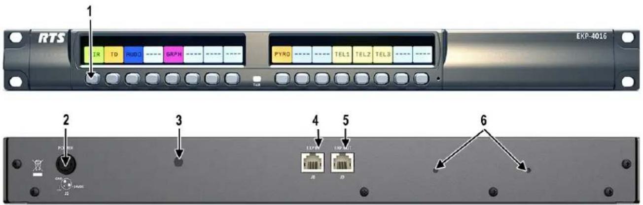
FIGURE 15. EKP-4016PB Expansion Panel Reference View – Front and Rear
- Expansion Keys
- Power
- Power Supply Bracket Mounting Holes
- RJ-45 Expansion IN
- RJ-45 Expansion OUT
- Power Supply Cable Tie Mounting Hole
Expansion Panel Cabling Reference
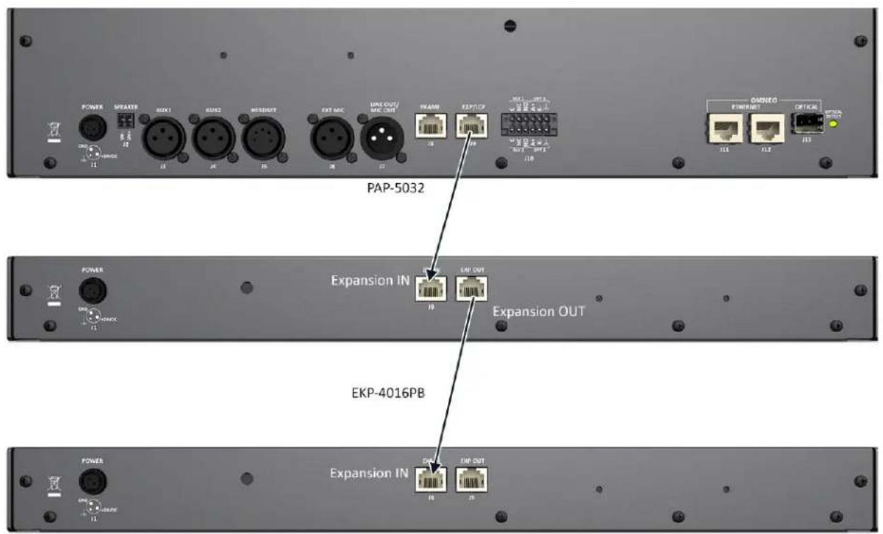
FIGURE 16. Expansion Panel Cabling
| RJ-45 EXP IN (expansion) | |
| Pin Assignment | |
| 1 No Connect | |
| 2 | NC |
| 3 | NC |
| 4 | NC |
| 5 | NC |
| 6 | NC |
| 7 RS485 + | |
| 8 RS485 - | |
| RJ-45 EXP OUT (expansion) | |
| Pin Assignment | |
| 1 | NC |
| 2 | NC |
| 3 | NC |
| 4 | NC |
| 5 | NC |
| 6 | NC |
| 7 RS485 + | |
| 8 RS485 - | |
AZedit and Unicode Support
Minimum firmware revision requirements for Unicode support are:
- All controllers (MCII-e, ODIN) and I/O cards (AIO-8/16, OMI and RVON-8/16) that support the PAP-5032 also support Unicode. Neither Cronus nor Zeus support PAP-5032.
• KP 32 CLD v1.3.0 or later
- KP 12 CLD v1.1.0
- RP-1000 v2.0.0
• KP12/4U v1A.0.26 (Cyrillic character set only)
• KP-5032/4016 v1.1.1
• PAP-5032 v1.0.0
To configure the panel for Unicode operation, do the following:
- On the panel, select Service|Alphas|8 Chars (Unicode)|Save and Restart.
NOTE: If using the panel with Japanese firmware, you must also configure the correct Intercom Mode.
- From the Options menu in AZedit, select Preferences.
The Application Preferences window appears.
- Select the Advanced tab.
The Advanced page appears.
- Select the Allow intercom resizing in ONLINE mode check box.
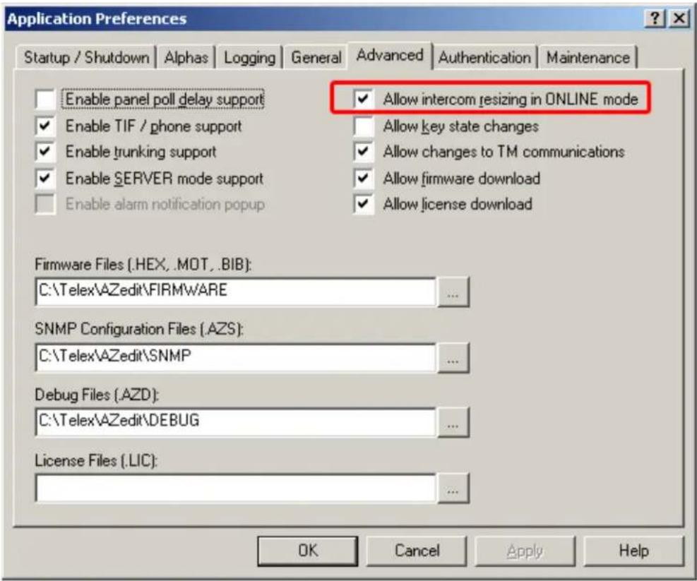
- Click Apply.
- Click OK.
The Application Preferences window closes.
IMPORTANT: You are about to erase the entire intercom setup! Be sure to save your file.
- From the Options menu, select Intercom Configuration. The Intercom Configuration window appears.
-
Click the Options tab. The Options page appears.
-
Select the Enable Unicode Alphas check box.
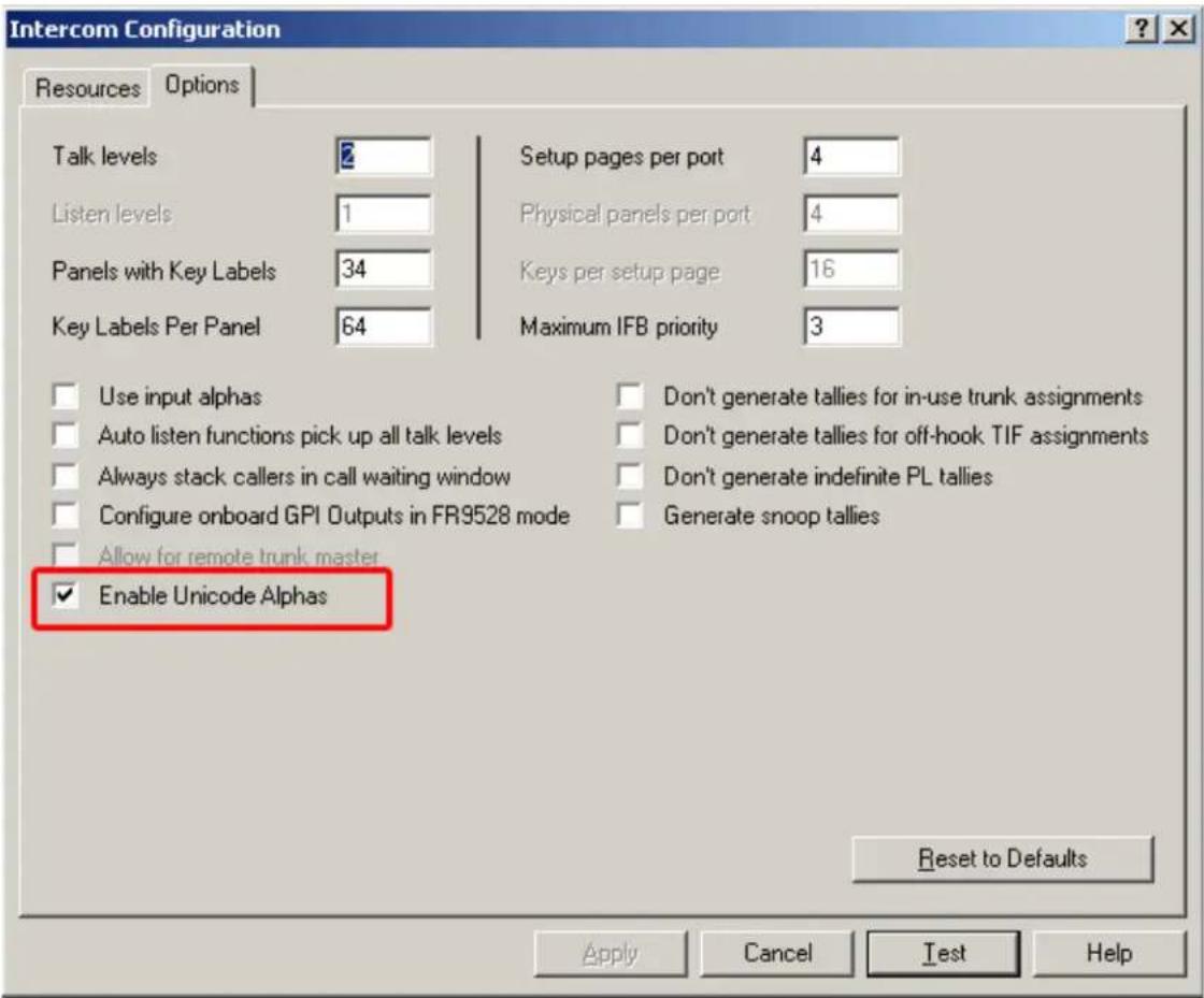
- Click Apply.
The Intercom Configuration window closes.
- From the Options menu, select Preferences.
The Application Preferences window appears.
- Click the Alphas tab.
The Alphas window appears.
- From the Preferred alpha size drop down menu, select 8-UNICODE characters.
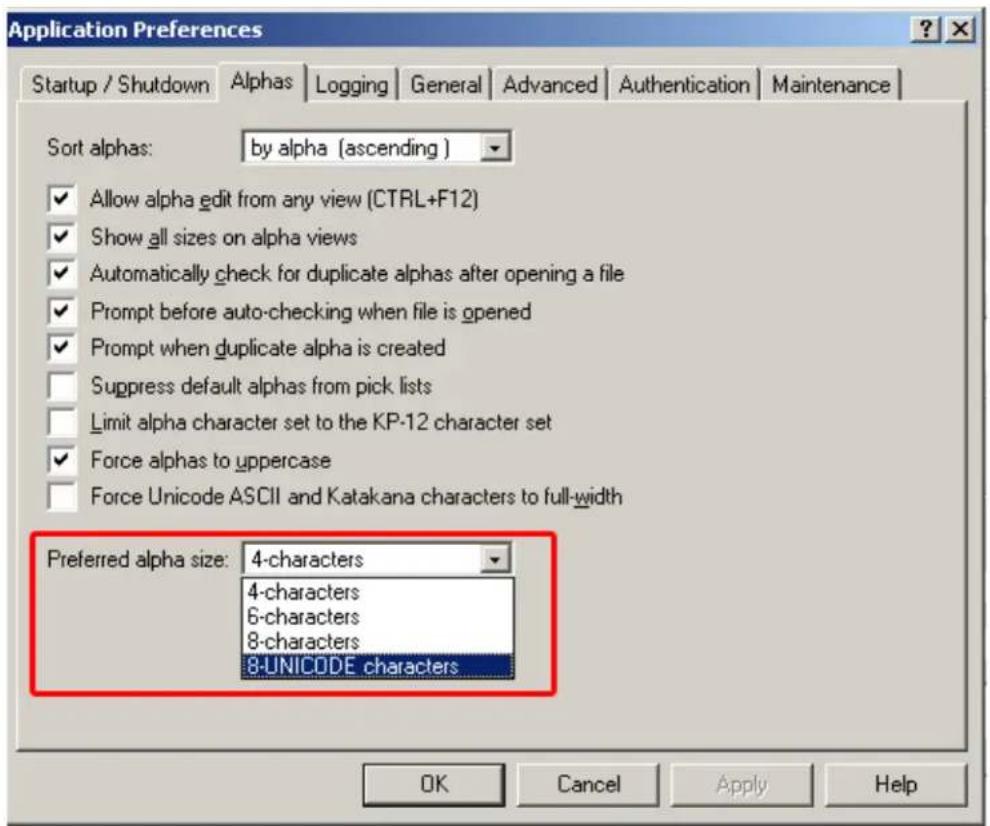
- Click Apply.
- Click OK.
The Application Preference window closes.
To restore the system configuration, do the following:
- From the Online menu, select Send File.
- Navigate to the system configuration file (.adm) you want to restore.
- Click OK.
Power Supply Mounting Options
Power Supply Mounting Bracket Instructions
Mounting the Power Supply to PAP-5032 Unit
To mount the power supply mounting bracket to a PAP-5032, do the following:
- Align the power supply mounting bracket screw holes with the appropriate mounting holes on the rear panel of the PAP-5032 unit.
- Using a screwdriver, attach the power supply mounting bracket with the two supplied screws.
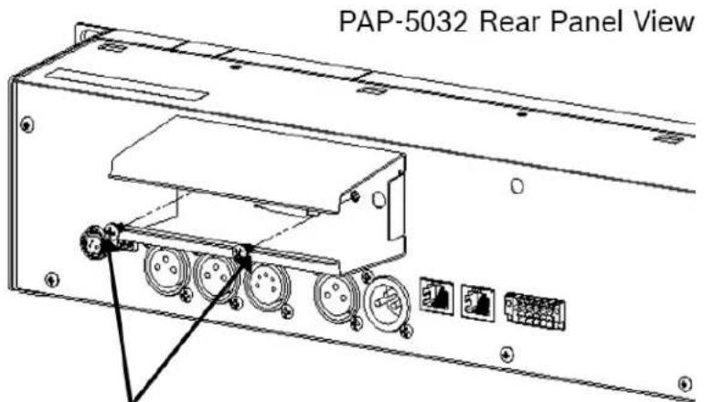
Mounting Screws
- Attach the power supply cable tie clip to the predefined clip mounting hole on the rear of the panel unit.
- Attach the DC power connector to the unit.
-
Carefully thread the power cable through the bracket, in order to utilize the power supply cable tie.
-
From the left-hand side of the mounting bracket, carefully slide the power supply into the bracket.
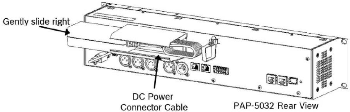
- Carefully coil the power supply cord and insert it into the cord clip.
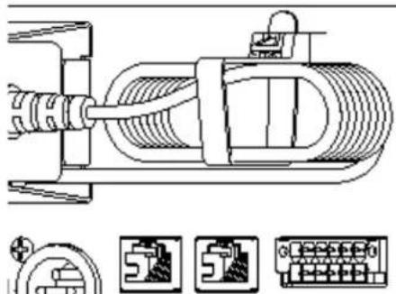
natural_image
Technical line drawing of a mechanical assembly with no visible text or symbols- Attach the AC power connector to the power outlet on the power supply.
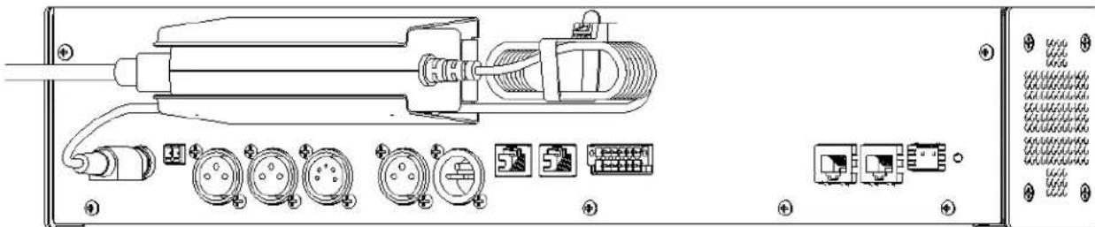
natural_image
Technical diagram of an electronic device with labeled ports and connectors (no readable text or symbols)PAP-5032 Rear Panel View
- Plug the power cord into an electrical outlet.
Mounting the Power Supply to EKP-4016/4016PB Unit
To mount the power supply mounting bracket to an EKP-4016, do the following:
- Align the power supply mounting bracket screw holes with the appropriate mounting holes on the rear panel of the EKP-4016 unit.
- Using a screwdriver, attach the power supply mounting bracket with the two supplied screws.
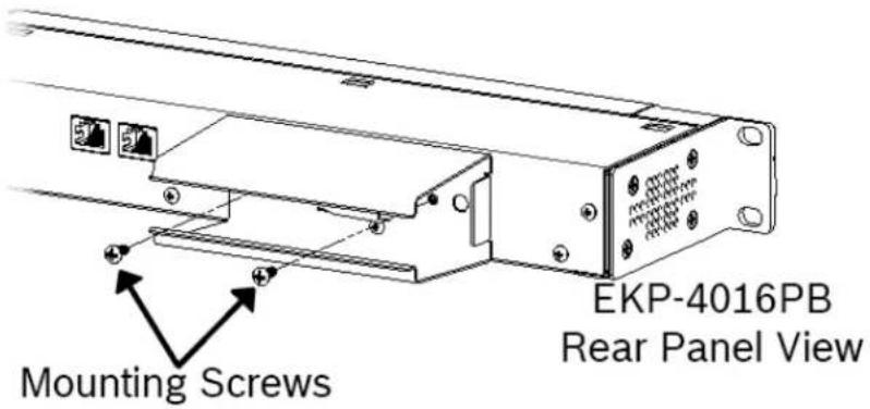
- Attach the power supply cable tie clip to the predefined clip mounting hole on the rear of the panel unit.
- From the left-hand side of the mounting bracket, carefully slide the power supply into the bracket.
NOTE: The Frame and EXP OUT connections cannot be populated until the power supply mounting bracket is fully installed.
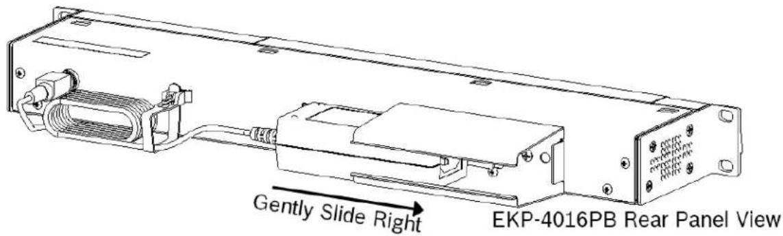
-
Attach the DC power connector to the unit.
-
Carefully coil the power supply cord and insert it into the cord clip.
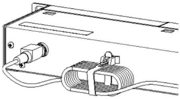
natural_image
Technical line drawing of an electrical connector with coiled cable and socket (no text or symbols)EKP-4016PB Rear Panel View
- Attach the AC power connector to the power outlet on the power supply.
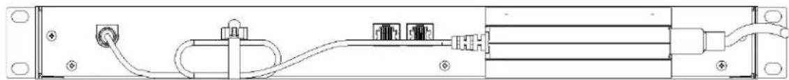
natural_image
Technical line drawing of an electronic device with ports, cables, and connectors (no text or symbols)- Plug the power cord into an electrical outlet.
Mounting the Power Supply to a Standard Rack
The Power Supply Mounting bracket can be directly attached to a standard rack, horizontally or vertically as shown in Figure 17 and Figure 18.
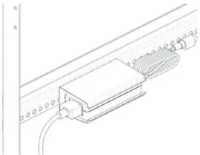
natural_image
Technical line drawing of a mechanical assembly with a coiled cable and housing (no text or symbols)FIGURE 17. Mounting Bracket – Horizontal on a Crossbar
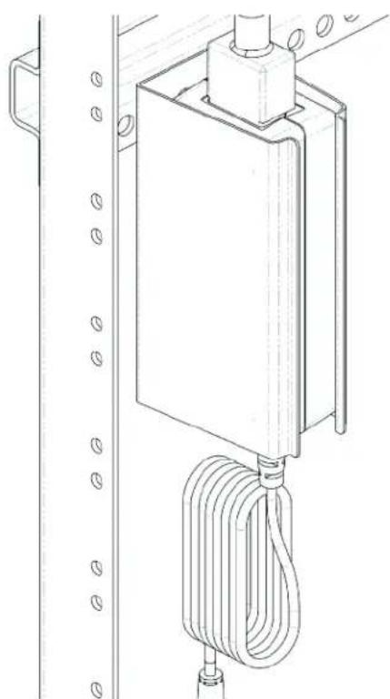
natural_image
Technical line drawing of a mechanical device with coiled cable and mounting bracket (no text or symbols)FIGURE 18. Mounting Bracket – Vertical from a Crossbar