SPK-300L - Intercom RTS - Free user manual and instructions
Find the device manual for free SPK-300L RTS in PDF.

| Product Type | Wired Intercom System |
| Model | SPK-300L |
| Brand | RTS |
| Dimensions (Main Unit) | 200 x 120 x 40 mm |
| Weight (Main Unit) | 0.5 kg |
| Power Supply | 12V DC via AC adapter |
| Audio | Full-duplex handsfree |
| Video | Not available (audio only) |
| Door Release | Supports electric strike connection |
| Number of Stations | Up to 2 indoor stations |
| Mounting | Wall mount (included) |
| Wiring | 2-wire connection |
| Range | 100 m maximum |
| Operating Temperature | -10°C to +50°C |
| Maintenance | Wipe with dry cloth; avoid liquids |
| Safety | Low voltage; use only supplied adapter |
| Spare Parts | Available from RTS distributor |
| Repairability | Professional repair recommended |
| Compliance | CE, RoHS |
Frequently Asked Questions - SPK-300L RTS
User questions about SPK-300L RTS
0 question about this device. Answer the ones you know or ask your own.
Ask a new question about this device
Download the instructions for your Intercom in PDF format for free! Find your manual SPK-300L - RTS and take your electronic device back in hand. On this page are published all the documents necessary for the use of your device. SPK-300L by RTS.
USER MANUAL SPK-300L RTS
The product information and design disclosed herein were originated by and are the property of Telex Communications, Inc. Telex reserves all patent, proprietary design, manufacturing, reproduction, use and sales rights thereto, and to any article disclosed therein, except to the extent rights are expressly granted to others.
COPYRIGHT NOTICE
Copyright 2006 by Telex Communications, Inc. All rights reserved. Reproduction, in whole or in part, without prior written permission from Telex is prohibited.
WARRANTY NOTICE
See the enclosed warranty card for further details.
CUSTOMER SUPPORT
Technical questions should be directed to:
Customer Service Department RTS/Telex Communications, Inc. 12000 Portland Avenue South Burnsville, MN 55337 USA Telephone: 800-392-3497 Fax: 800-323-0498 Factory Service: 800-553-5992
RETURN SHIPPING INSTRUCTIONS
Customer Service Department
Telex Communications, Inc. (Lincoln, NE)
Telephone: 402-467-5321
Fax: 402-467-3279
Factory Service: 800-553-5992
Please include a note in the box which supplies the company name, address, phone number, a person to contact regarding the repair, the type and quantity of equipment, a description of the problem and the serial number(s).
Shipping to the Manufacturer
All shipments of product should be made via UPS Ground, prepaid (you may request from Factory Service a different shipment method). Any shipment upgrades will be paid by the customer. The equipment should be shipped in the original packing carton. If the original carton is not available, use any suitable container that is rigid and of adequate size. If a substitute container is used, the equipment should be wrapped in paper and surrounded with at least four (4) inches of excelsior or similar shock-absorbing material. All shipments must be sent to the following address and must include the Proof of Purchase for warranty repair. Upon completion of any repair the equipment will be returned via United Parcel Service or specified shipper, collect.
Factory Service Department
Telex Communications, Inc.
8601 Cornhusker Hwy.
Lincoln, NE 68507 U.S.A.
Attn: Service
This package should include the following:
flowchart
graph TD
    A["200-12 IMPEANCE REGULATOR"] --> B["DC SOURCE"]
    C["200-12 IMPEANCE REGULATOR"] --> B
    B --> D["CHANNEL 2"]
    B --> E["CHANNEL 1"]
    B --> F["COMMON"]
    D --> G["1 VOLT PEAK AUDIO 28-32 VOLT DC"]
    E --> H["28-32 VOLTS DC"]
    F --> I["2"]
    J["100-240 VAC"] --> K["MICROPHONE AMPLIT"]
    L["USER STATION"] --> M["MICROPHONE OFF ON"]
    M --> N["MICROPHONE PREAMPUMPLIFER AND LIMITER"]
    N --> O["CLIPRENT SOURCE DRIVER"]
    O --> P["SIDETONE ADJ 1"]
    P --> Q["VOLUME CONTROL"]
    Q --> R["HEADPHONE/ SPEAKER AMPLIFIER"]
    R --> S["DC POWER"]
    S --> T["REGULATOR"]
    U["USER STATION"] --> V["1 2 3"]
    W["USER STATION"] --> X["1 2 3"]
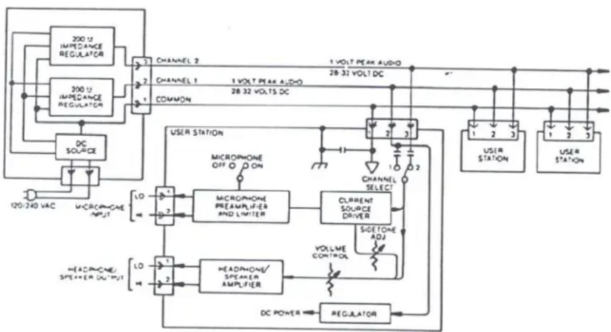
FIGURE 1. TW System Concept Block Diagram
DESCRIPTION
The Model SPK300L, a Portable Speaker User Station, is a component used in the TW INTERCOM SYSTEM. Each User Station is a communications unit along a multi-unit conference bus.
Figure 1, “TW System Concept Block Diagram,” on page ii, shows User Station interconnection, and User Station connection to the system power supply.
User Station interconnection can be: 1) centrally wired, with each cable coming from a central point, or 2) distributed, where all the user stations are looped together from one to another, or 3) a combination of both. The centrally wired interconnection not only reduces interchannel crosstalk, but also allows for easier expansion into an assignable channel, multi-channel system.
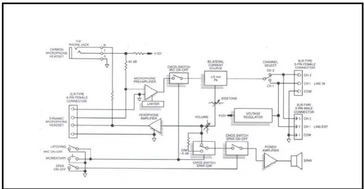
Figure 1, "SPK300L Block Diagram," on page 3, shows user station functional components, input/output connections, and controls.
The SPK300L User Station has the following
functional components:
- a microphone preamplifier with limiter
- an electronic microphone switch
- a "bilateral current source" line driver
- a listen volume control
- a headphone amplifier
- a speaker amplifier
- a speaker switch
- a channel selector switch
The Microphone Preamplifier/limiter converts the small microphone signal to a strong line level signal conditions the signal strength from loud and soft talkers to be almost the same sends the signal to the line via the microphone switch and a "bilateral current source".
The Bilateral Current Source adds signal, via the channel select switch, to the line without affecting any signals already on the line. The bilateral current source also extracts the listen signal from the line and sends it to the headphone amplifier via the volume control. Some of the user's own voice signal ("sidetone") is also fed to the headphone amplifier.
The Channel Selector Switch selects the channel on which the user will talk and listen. The headphone amplifier output drives the user's headphones.
The Volume Control also feeds the speaker amplifier via the speaker switch and the speaker dim network.
The User Station Voltage Regulator takes power from channel 1, regardless of the channel selector switch setting (exception: local power option units). The regulator not only supplies regulated power to the user station, but also prevents unwanted interaction between the user station and the intercom line which is supplying the power. Because the regulator takes power from channel 1, channel 2 can be expanded into many channels by using a switch and, for each channel, a separate wire and a termination network consisting of a 200 ohm resistor and a 10 microfarad capacitor in series. (See the Application Diagrams in the TW Intercom Systems Technical Manual).
A TW System Power Supply terminates a line with 200 ohms.
Operational Controls
The SPK300L User Station has the following controls, described and shown in Section 3:
- Channel Select Switch
- Latching-action Microphone ON-OFF toggle switch.
- Momentary-action Microphone ON-OFF pushbutton switch.
- Speaker/Headphone Volume Control
- Call Switch /indicator
- Speaker ON/OFF switch
- Sidetone Adjustment
Connection, Inputs and Outputs
The SPK300L User Station has four input/output connectors:
• Dynamic Microphone type headset or handset
• Carbon Microphone type headset or handset
• Line Input (ties the station to the intercom line
- Loop/extension (allows another station to access the line through the first station. Also called loop-through.
flowchart
graph TD
    A["CARBON MICROPHONE HEADSET"] --> B["1/4" PHONE JACK"]
    B --> C["7"]
    C --> D["5"]
    D --> E["+12V"]
    E --> F["40 dB"]
    F --> G["CMOS SWITCH MIC ON-OFF"]
    G --> H["BLATERAL CURRENT SOURCE ±5 mA Pt"]
    H --> I["CHANNEL SELECT CH 2"]
    I --> J["XLR-TYPE 3-PIN FEMALE CONNECTOR"]
    J --> K["CH 2"]
    K --> L["LINE IN"]
    L --> M["COM"]
    M --> N["XLR-TYPE 3-PIN MALE CONNECTOR"]
    N --> O["CH 2"]
    O --> P["LINE/EXT"]
    P --> Q["COM"]
    Q --> R["SPKR"]
    R --> S["POWER AMPLIFIER"]
    S --> T["VOLTAGE REGULATOR"]
    T --> U["CMOS SWITCH SPKR-ON-OFF"]
    U --> V["CMOS SWITCH SPKR-DIM"]
    V --> W["VOLUME"]
    W --> X["LIMITER"]
    X --> Y["HEADPHONE AMPLIFIER"]
    Y --> Z["XLR-TYPE 4-PIN FEMALE CONNECTOR"]
    Z --> AA["DYNAMIC MICROPHONE HEADSET"]
    AA --> AB["1/2"]
    AB --> AC["2/3"]
    AC --> AD["3/4"]
    AD --> AE["4/5"]
    AE --> AF["LATCHING MIC ON-OFF"]
    AF --> AG["MOMENTARY"]
    AG --> AH["SPKR ON-OFF"]
    AH --> AI["+12V"]
    AI --> AJ["VOLUME -6 dB"]
    AJ --> AK["CMOS SWITCH SPKR-DIM"]
    AK --> AL["VOLUME +12V"]
    AL --> AM["SIDETONE"]
FIGURE 1. SPK300L Block Diagram
Specifications
| Audio Line Voltage | 1 volt, peak (0 dBm voltage-equivalent) |
| Average Speech Level Range | -20 dBV to -10 dBV |
| Absolute Maximum Spccch Level | 3 volts, peak (linear limit) |
| Audio Line Impedance, Nominal | 200 50 ohms, 75 Hz to 20 kHzSystem will continue to operate from 50 ohms to 300 ohms. |
SYSTEM DC CURRENT
| Nominal 32 volts DC | |
| Operational Range | 18 to 35 volts DC |
| Steady state without damage | -1.5 volts to 36 volts DC |
| Transient 200 volts, 8 milliseconds or less (after this time, power supply and user station fuses will open). | |
| System DC Current | |
| Quiescent (per station) | 10 to 40 milliamps |
| Dynamic (per station) | 50 milliamps (w/25 ohm headphones)70 milliamps (w/25 ohm headphones and lights)100 milliamps (w/8 ohm speaker) |
| Start-Up Current | 1.25 amperes, 50 units, all kinds |
| Fault Current 4.0 amperes, power supply at voltage >12 volts1.0 amperes, power supply at voltage <12 volts | |
OPERATING DISTANCES
| Maximum DC limit | 5,000 ft distance along cable, power supply to single station #22 gauge wire - DC voltage drop limitation. |
| Maximum AC limit | 10,000 ft. dry pair, power supply at each end, #22 gauge wire |
| System Capacitance | 0.3 microgarads (cumulative effect of 10,000 ft. of maximum cable at 30 picofarads/foot) |
| USER STATIONS SPECIFICATIONS | |
| Input DC voltage | 20 to 35 volts DC, operating from -200 to +36 volts DC without damage. |
| DC Current Quiescent, 10 to 40 milliamps | |
| 50 milliamps, typical (w/25 ohms headphones) | |
| 75 milliamps, typical (w/25 ohms headphones + lights) | |
| 100 milliamps, typical (w/8 ohm speaker) | |
| Impedance Across Line | 10,000 ohms typical; 2,000 ohms worst case dynamic operation |
| Ambient Temperature Range | Operating 0^ C to 60^ C ( 0^ F to 140^ F)Storage -55^ C to 125^ C ( -67^ F to 257^ F) |
| Noise Contribution to 200 ohm Line | One unit: -75 dBuTen unit: -67 dBu |
| MICROPHONE PREAMPLIFIER | |
| Input Impedance * | 470 ohms |
| Source Impedance* | 200 ohms, nominal |
| Maximum Input Level | 150 millivolts |
| Voltage Gain 54 dB | |
| Frequency Response | 100 Hz to 10,000 Hz, 3 dB |
Introduction
Limiter Range 50 dB
Carbon Mic 10 milliamps, nominal
Excitation
Current
CURRENT SOURCE
Transfer Ratio 5 milliamps/1.5 volts
Output 5 milliamps into 200 ohms
HEADPHONE AMPLIFIER
| Overall Voltage Gain | 24 dB |
| Overall Voltage Gain | 9 volts peak-to-peak into 25 ohms |
| Output Power Headset Station: 1/2 watt into 25 ohmsSpeaker Station: 2 watts into 8 ohms | |
| Frequency Response | 150 Hz to 8000 Hz, 3 dB |
| Headphone Impedance Range | 25 to 600 ohms |
| Sidetone Adjustment Range | 20 dB to full ON |
CALL LIGHT
| Signaling Frequency | 20,000 kHz 3dB |
Flashing Rate 3Hz 2 Hz
DIMENSION
| 3.468" H x 1.5" W x 3.0" D (13.21 x 3.81 x 7.62 centimeters) |
MECHANICAL INSTALLATION
The Model SPK300L Portable Speaker User Station is 4.0 inches (101.6 mm) high X 8.0 inches (203.2 mm) wide X 8.0 inches (203.2 mm) deep. Additional depth should be allowed for the rear panel XLR-type line connectors. When installing this unit, allow space for control access, cabling and servicing. Provide space for: cabling service loops, reaching XLR-type connector lock releases, and headset connector/cables. If the headset connector is remotely located, allow space between this cable and interference sources such as video/TV monitors, power supplies and equipment with internal power supplies. There are no ventilation requirements.
Headset Requirements
Dynamic microphone headset type:
- 50 to 1000 ohm microphone
• 25 to 1000 ohm headphone(s)
High efficiency headphones are recommended because less line current is required from the power supply. Use headphones with an impedance of 25 ohms or greater. Low impedance 8 ohm headphones are not recommended. Headphones with good acoustic isolation (20 to 40dB) improve communication in high ambient noise environments, and allow the user to use the headphones at a less tiring, lower volume.
In the headset connecting cable, prevent coupling between the microphone and headphone leads by using a shielded, twisted pair for the microphone, and a separate, twisted pair for the headphones. Do not allow headphone ground to contact microphone ground or shield. Tie the shield to microphone ground or "mic low". The headset cable can be made longer when the microphone and headphone pairs are physically separated. The wider the separation, the longer the cable length which may be used. Estimated maximum usable headphone cable lengths are as follows:
Single cable,
Two shielded twisted pair 10 ft. (3 m).
Dual ribbed cable,
Two shielded twisted pair: 30 ft. (9 m).
ELECTRICAL
Power
The SPK300L receives electrical power from either:
(1) a system power supply (26 to 32 volts DC on line connector pins 2 (+) and 1 (com) (1 or two channel operation); or
(2) a local power supply option (14 to 26 volts DC). A user station requires 18 to 33 volts to be a 10,000 ohm bridging impedance across the powering line, but the station can otherwise operate (as in the local power option) from 12 to 33 volts.
When using a local power supply option, each channel requires a 200 ohm load. See Figure 1-1. It is necessary to do this only once for each channel string.
Model SPK300L current requirements range from 30 to 100 mA; Since, in (1), above, the power and communications signals may share conductors, it may be necessary to overcome power losses by increasing conductor size over long runs (over 1/2 mile (804 m)). Typical operating distance for one SPK300L station is 1/2 mile (.80 km), and for one SPK300L, 1/3 mile (0.53 km) using a normal # 22 AWG conductor size.
Signal
The required number of conductors to interconnect user stations is as follows (For standard unbalanced TW user stations):
| # of Channels | # of Conductors | ||
| 1 | 2 * | ||
| 1 | 3 | * | * |
23***
*Using a TW power supply (and possibly operating on a TW system).
**Using a non-TW power supply.
***Using a TW power supply and operating on a TW two channel system.
Use shielded cable to interconnect user stations in areas of possible electrical interference, (areas such as those near: digital equipment, high current primary power conductors ("mains"), transformers, transmitters, and lamp dimmers).
Most two channel applications may use either standard microphone cable (for convenience) or two-twisted-pair cable (considerably less expensive than microphone cable). Standard wire size for the TW Intercom System is #22 gauge wire for interconnection. For permanent installations it is recommended that each channel should have individually shielded twisted pair of at least #22 gauge wire, such as Belden #8723 for 2 channels. Connect the shield to system common but do not tie the shield to chassis, earth or connector shell ground.
Crosstalk Control
In the TW Intercom System all channels share a common circuit ground return. Crosstalk due to common ground resistance can be lowered by reducing the common ground resistance. Reduction of ground resistance can occur as a side benefit of using shielded cable, since the shield drains can be tied together and electrically parallel the circuit ground. Another way of lowering resistive crosstalk is to "homerun" all interconnecting cables to a central or "home" location. In this configuration, the ground path is short and the corresponding ground resistance is small. Crosstalk due to mutual capacitance occurs when the signal on one wire of a twisted pair couples into the other wire. Separating the two conductors with a shield greatly reduces the capacitive crosstalk.
To reduce both capacitive and resistive crosstalk and to afford a degree of RF and electrostatic shielding, use a cable which has a shielded twisted pair for each channel. Each pair consists of a conductor for the channel, a conductor for circuit ground return and a shield around the two conductors. The shield is accessed via a drain conductor. This drain conductor and the shield can augment the circuit grounds and thus lower the ground resistance.
USER STATION CONNECTIONS
Routing the TW Intercom System cables along the same ductways and pathways as power cabling can increase the noise and hum levels.
Moisture / Contamination Protection
When using equipment in the rain, always protect the equipment with plastic covers----also, make sure all cable connectors are lifted out of the mud or snow and protected with plastic bags. Water, mud and snow in connectors can cause considerable audible noise.
Hum Prevention
Prevent inducing hum into the system by not locating user stations near hum sources such as power transformers, electrical switch panels, lamp dimmers or TV cameras. When the microphone switch is turned on, the dynamic microphone acts as a sensitive antenna for hum sources.
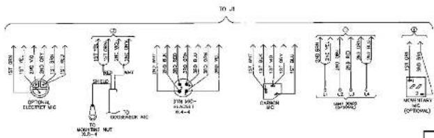
USER STATION CONNECTIONS
Dynamic Microphone headset connector:
XLR-4-31 type receptacle (J1)
Input level: -55 dbu nominal
Output level to headphone: 10 volts peak-to-peak open circuit.
Pin 1 - Microphone low
Pin 2 - Microphone high
Pin 3 - Headphone low
Pin 4 - Headphone high
Carbon Microphone headset connector:
Standard 1/4" Phone Jack (J2)
Input level: -15 dbu nominal
Output to Headphone: 10 volts peak-to-peak open circuit.
Tip - Carbon Microphone
Ring - Headphone
Sleeve - Common/ground
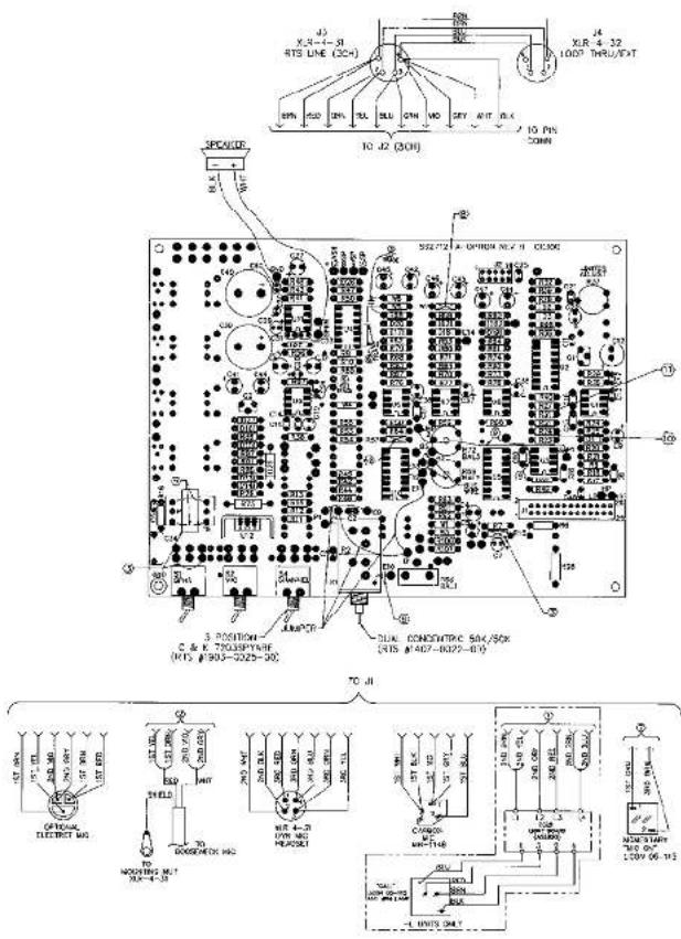
Line input connectors: (J3/J4)
XLR-3-31/32 types (for two-channels)
Pin 1 - Common (low side of line)
Pin 2 - Channel 1
Pin 3 - Channel 2
XLR-4-31/32 types (for three-Channels)
Pin 1 - Channel 1
Pin 2 - Channel 2
Pin 3 - Channel 3
Pin 4 - Common (low side of line)
INSTALLATION
Operating Controls
The table below lists the Model SPK300L operating controls. The reference numbers in the table correspond to the circled numbers in Figure 3-1.
TABLE 1. Model SPK300L Operating Controls
| REF NO. NAME DESCRIPTION | ||||
| 1 Channel Select Switch | Selects one of two channels (standard) or one of three channels (optional). The Call Light Option transmitter and receiver operate on the channel selected by this switch.The Channel Select Switch is omitted in the Single Channel (SC) option. | |||
| 2 Mic ON/OFF Toggle | A latching action switch. Turning ON the microphone slightly “dims” or attenuates the speaker. | |||
| 3 Mic ON/OFF Pushbutton | A momentary action pushbutton switch. Not standard with the Call Light Option.Turning ON the microphone here also slightly “dims” or attenuates the speaker. | |||
| 4 | V | o | l | A speaker / headphone volume control. May be dual control for the Duel Listen (DL)or Program (E) Option.CAUTION: Always turn this control all the way couter-clockwise (to the left) before plugging in the headset. |
| 5 Call Light Indicator | This switch / indicator appears only on the user stations with the Switch “Call Light” option. When depressed, this switch adds a 20 kilohertz signal to the TW intercom line on the same channel that the Channel Select Switch has been set. This signal activates the Call Light Receiver on all user stations which are switched to the same channel.This switch: | |||
| 6 | S | p | e | 1. turns the speaker ona k e r O N /2. disables the headset microphone3. enables the panel |
| 7 | S | i | d | The screwdriver adjusted SIDETONE control sets the “sidetone” level during headset operation and sets the “balance”nulling during speaker / panel microphone operation. |
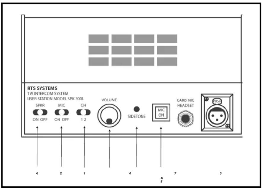
FIGURE 1. SPK300L Reference View
Adjust the Sidetone
To adjust the SIDETONE control for speaker operation, do the following:
- Turn ON the speaker switch.
- Turn ON the microphone switch.
- Set the VOLUME control to about 50%
- Hum into the panel microphone and adjust the SIDETONE for minimum sound through the loudspeaker.
To adjust the SIDETONE control for headset operation, do the following:
- Turn OFF the speaker switch.
- Turn ON the microphone switch.
- Plug in a headset.
- Set the VOLUME control to about 50%.
- Turn the SIDETONE control fully counter-clockwise, then adjust it clockwise for a comfortable level of your own voice while talking into the headset. microphone.
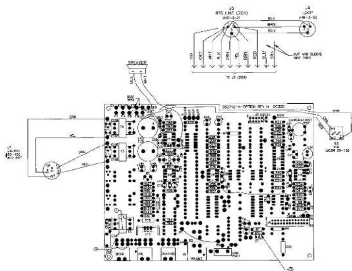
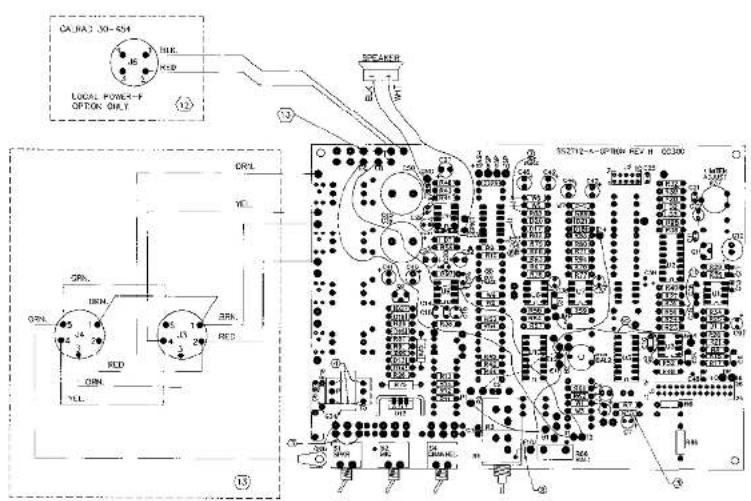
EN5541 - Installation, Local Power Option, RMS300 and SPK300L
The RMS300 and SPK 300 can be powered from an external (local) power supply of between 18 to 33 volts DC. the local power option, as supplied by RTS Systems, uses a power supply assembly (RTS # 9020-4425-00), which is 117 VAC, 60 Hz in, 24 VDC 400 mA out.
To modify the RMS300 or SPK300L for local power operation, do the following:
- Remove diode D26 from the CC300 P.C. board.
- Add J6, 4-pin jack (Calrad #30-454, RTS # 2013-0005-00), to the back panel.
- Wire, as shown in the diagram below. Pin 1 = common, Pin 2 = external supply + (18 to 33 VDC).
Operating Controls
- Wire PG, 4-pin plug (Calrad #30-453, RTS # 2013-0016-00) to the external supply: Pin 1 = common, Pin 2 = external supply +.
- Plug P6 into J6 on the RMS300 or SPK300L back panel.
NOTE: If using RTS local power option kit 9002-5541-00, the external supply will already be wired to P6. Obsolete products have been discontinued and are no longer available for purchase.
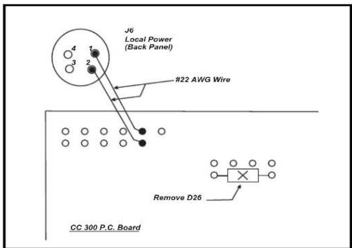
FIGURE 2. CC300 P.C. Board modifications.
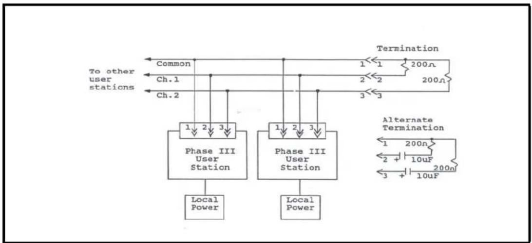
When a system is constructed using locally powered user stations, it is essential that all channels are terminated with a 200 ohm system termination. System terminations (see diagram below) include:
An RTS System TW power supply *
• A discrete 200 ohm resistor for each locally supplied channel
- When application of a D.C. voltage is expected or possible, a 10 microfarad / 50 Volt capacitor in series with the 200 ohm resistor for each locally supplied channel.
flowchart
graph TD
    A["To other user stations"] --> B["Ch.1"]
    A --> C["Ch.2"]
    B --> D["Phase III User Station"]
    C --> E["Phase III User Station"]
    D --> F["Local Power"]
    E --> G["Local Power"]
    H["Termination"] --> I["1"]
    H --> J["2"]
    H --> K["3"]
    L["Alternate Termination"] --> M["1"]
    L --> N["2"]
    L --> O["3"]
    M --> P["10uF"]
    N --> Q["10uF"]
    O --> R["200n"]
    style A fill:#f9f,stroke:#333
    style H fill:#ccf,stroke:#333
FIGURE 3. Power Supply diagram
*Examples of RTS System power supplies are:
PS8, PS10, PS15, PS20, PS30, PS31, PS50, and PS60.
OPERATION
CHAPTER 4
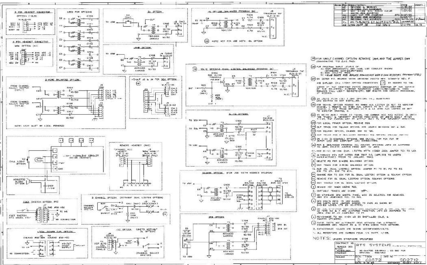
DRAWINGS
Model SPK300L
Number TitleS
—
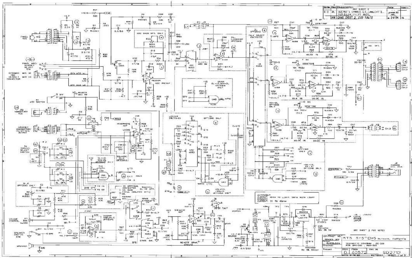
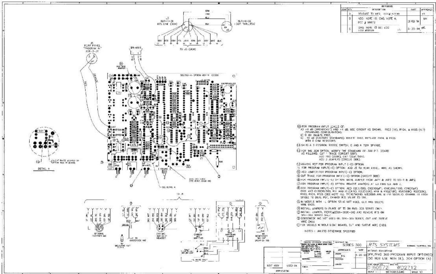
D2712 Schematic Diagram, CC300, page 1 of 3
SD2712 Schematic Diagram, CC300, page 2 of 3
SD2712 Schematic Diagram, CC300, page 3 of 3
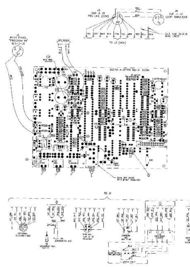
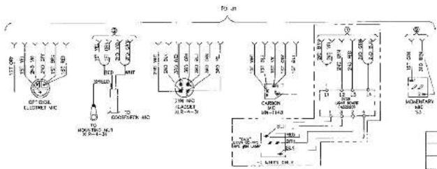
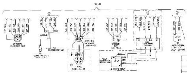
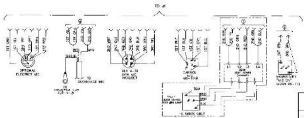
Wiring for External Microphones
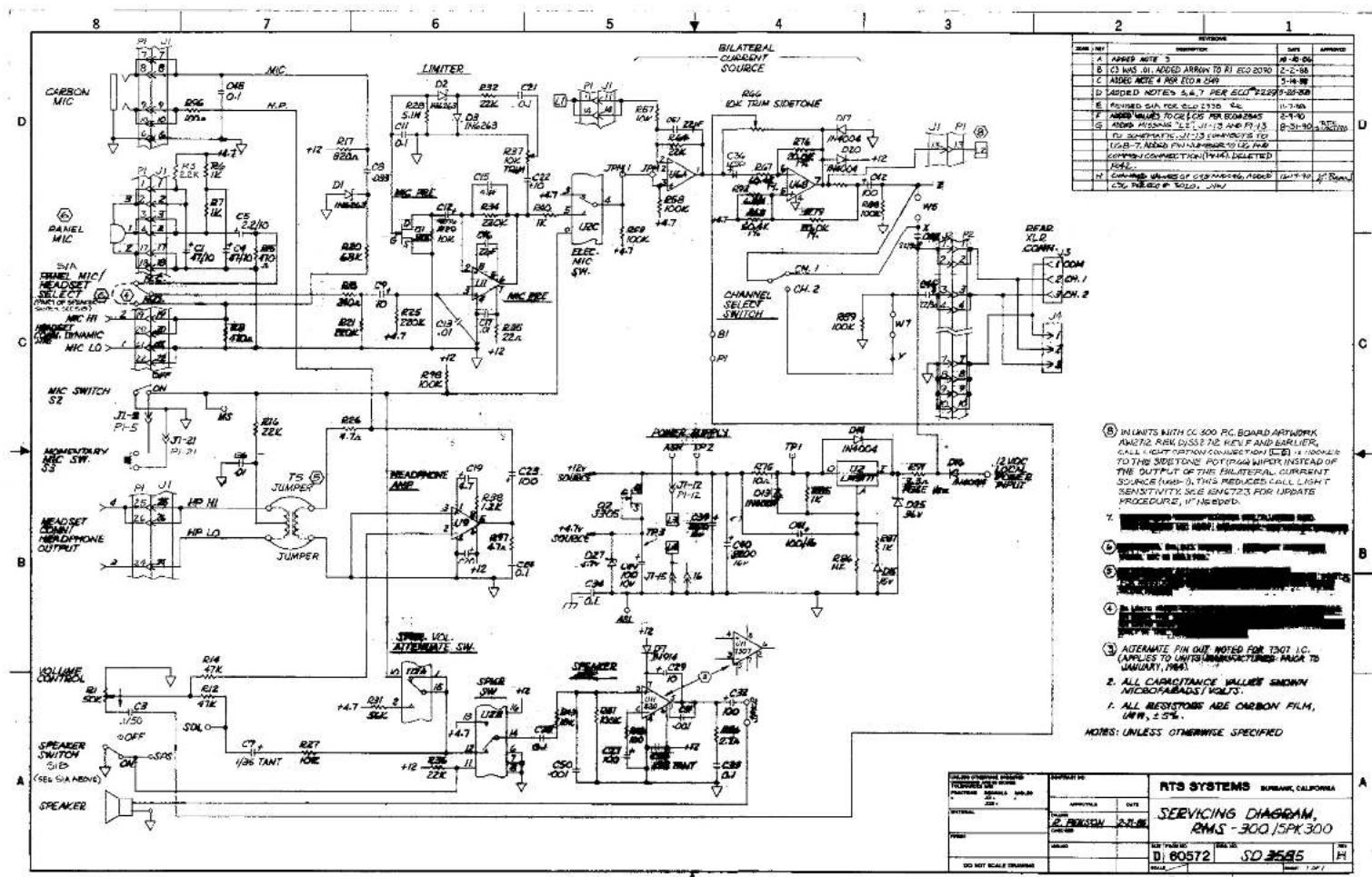
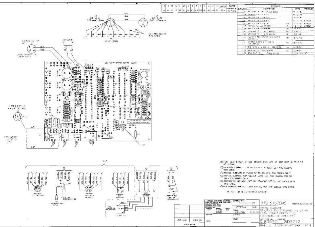
SD3585 Servicing Diagram, Model RMS300/SPK300L,
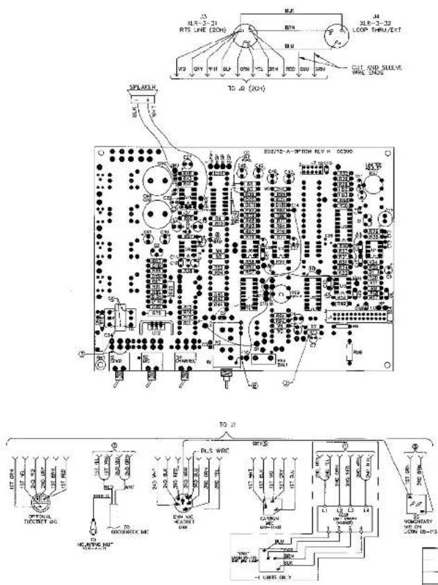
WD2712 Wiring Diagram, pg. 1 of 7
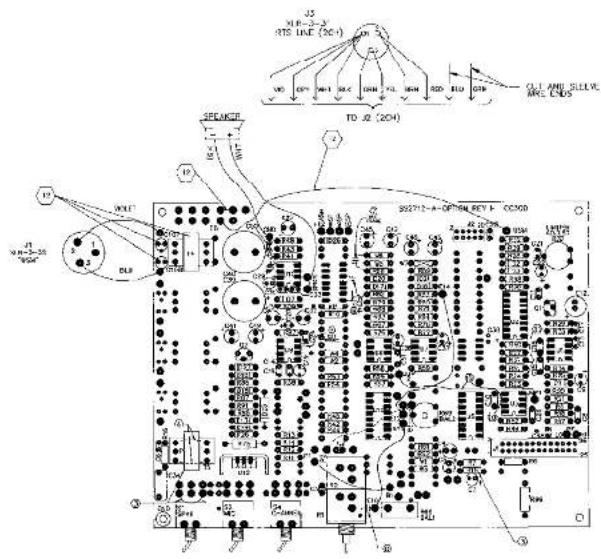
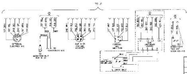
SPK/RMS300 Standard -L Option and Local Power Option
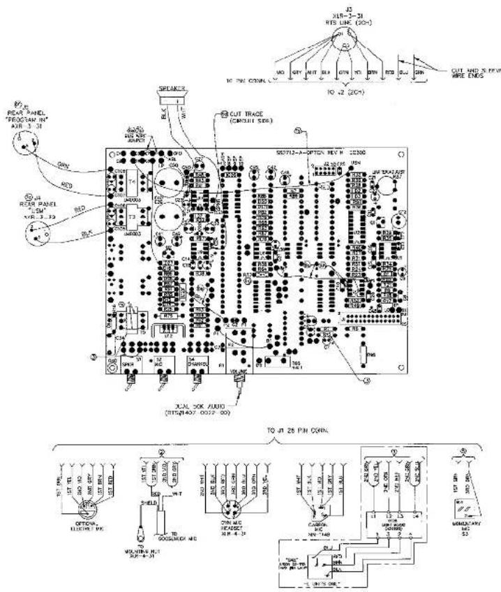
WD2712 Wiring Diagram, pg. 2 of 7
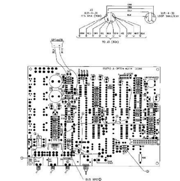
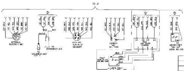
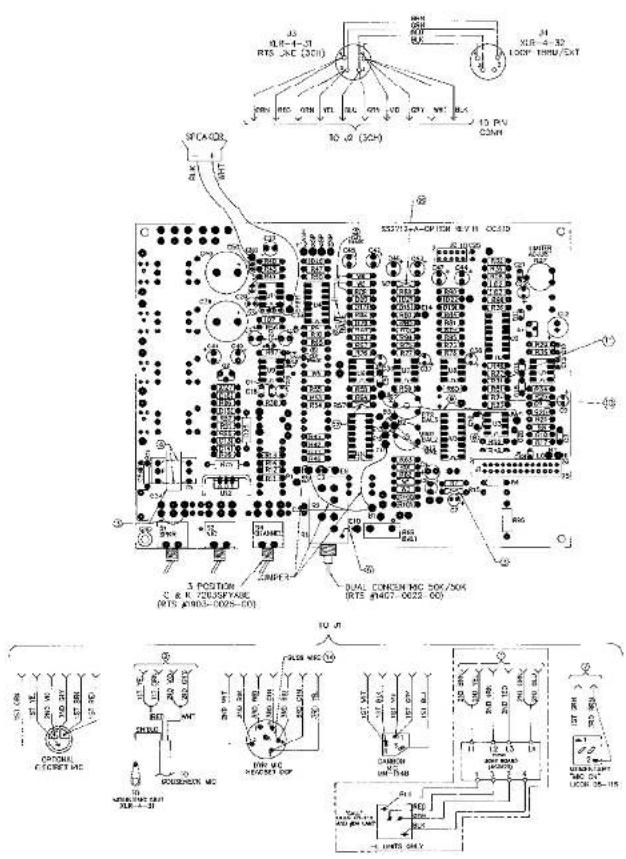
SPK/RMS300 3CH and 3CH-L Options
WD2712 Wiring Diagram, pg. 3 of 7
SPK/RMS300-DL
WD2712 Wiring Diagram, pg. 4 of 7
SPK/RMS300, FB Option
WD2712 Wiring Diagram, pg. 5 of 7
SPK/RMS300-DL-3CH
WD2712 Wiring Diagram, pg. 6 of 7
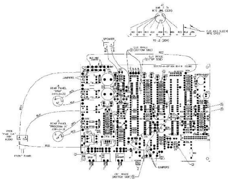
SPK/RMS300 Program Input Option
WD2712 Wiring Diagram, pg. 7 of 7
SPK/RMS300 DL (Dual Listen) - E (Program Input)
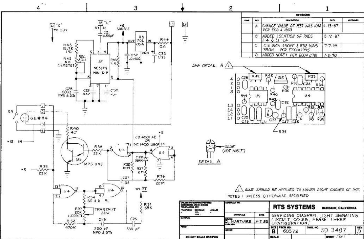
SD3487 Servicing Diagram, Light Signaling Circuit
CC-28, Phase III configuration
DISTERICH-POST CLEARPRINT
② FOR SINGLE CHANNEL OPTION REMOVE SNR, AND THE LUMPER SNR CONVOWED TO ONE PAD
610 000754 3287 5975
(2) FOR THE POWER OF CHINA A) ROD (BROADCAST) AND PADS, USE CIRCUIT SHOWN (STANDARD CHECK BUTTON)
B: 363 DELETE
0: -16.28 SOUT RNS REPLACE RINKING NOT WITH O SHAK RESISTERS (AVOCHE'S 3720.)
[27] ON 30700 P.C. HOJINX WITH ANTONIX AVIYTO REV. 0/20210 16V. F
AND EARTH CALL LIGHT OPTION CONNECTION 1.7 IS MODED TO THE VARIATION OF THE STOCTONE POT(5) (OMASCOAT2) INSTEAD OF THE OUTPUT OF THE RELATATE CURRENT SODUCTS (LAM-310N-320M-1). THIS REDUCE CALL LIGHT SOUSITIVITY, SEE FAM/310N FOR IMPACT PROCESSES, IF REODED
C
25 IN JITS PCTIN LNT 1,000 10
FOR DOHO, OPTION REMOVE MS WHEN AUC LISTEN IS SET TO VIEW CHANNEL 1. REMOVE MS WHEN AUC LISTEN IS SET TO VIEW CHANNEL 2. OUT TRADE BETWEEN U-3 & L3 WHEN AUC LISTEN IS SET TO VIEW CHANNEL 3.
② 用INCTS, 将1.0MPa, 12.5MPa, 13.6MPa, 14.4MPa, 15.8MPa
THE "FUEL" & "HEADSET" SWITCH POSITIONS IN UNITS BUILT AFTER
(1) 2017年1月1日
(2) FOR INFORMATION OPTION, IS-NAME: NEW TC
- 2017-106:14, 1995-106:24, 2017-106:14, 1995-106:24
(12) ON 3-OH (CHANNEL) OPTIONS. SEE DETAIL FOR PIN CUT OR TRANSIT (LOT) ARE LOOP/EXP (JL) CORPACTORS.
(1)
18 FOR E (BALANCED PROCESAL INC), HOLAWK OPTION: JMPX IS JUMERED TO JMPX. PAUTE JUMEN FROM .BOP TO JMPX
- PER IN 2011 CHISON, 2014 + LATEM, MTEM VIDEO 1950. AMPER TE: TO LOU
16 ALTERNATE PIN OUT NOTED FOR 7907 TC. (APPLITIS TO EXITS
[14] OUT TRACE FOR 2-WIRE BALANCED OPTION.
(2) 508.41 (Pul: LISTE): OPTION: (HESR B): TO B1, B2, TO B3
510 TO 61. 512 TO 614
12 CHANGE 804 TO 954 FOR DL (FULL LESTON) OPTION & SQUARE OPTION
8
(ii) RESOLVE FOR DC (SOLD LISTROOM) OFFICE SOUTH AVAIL OFFICE
(10) BUT TRAVES FOR GL (200-L CLT-CH) 007204
- ANS 3W JOG-CHD NO. 15 NO.
(6) SPK UNITS HAVE TO INS ALLIED
RUG UNITS HAVE JUMPERS ACROSS DAP-ED LIVES. (TS IS DELETED)
② TICF, NCTD, AEF, ALTERNATE, OTAS, AETNOSIC, C90, ALTERNATE
③ COMENERS AND REMOVE AS & CI WHEN USING THIS NETWORK.
-
01748765-39, 0175-129, 020-129
-
CAPSITANCE VALUES THE SHOWN WORKFUND/VEGETS
-
ALL RESISTORS ARE CABBON FILM 1/4 WATT. +/-8%
(1) 2023
NOTES: UNLESS OTHERWISE SPECIFIED
| CONTRACT NO. RPNLES 300 Cron- RPNES-200 Checked | RTS SYSTEMS | |
| SC-GMATS SC-BRAV, CC 500 PCR SPX-300, PAX-400 | ||
| Designed | ZL2A 72614 | 300 NC |
| D C0572 | SD2712 | |
| DATE: 8/12/09 | 20270902 ELECT. 2017 | |
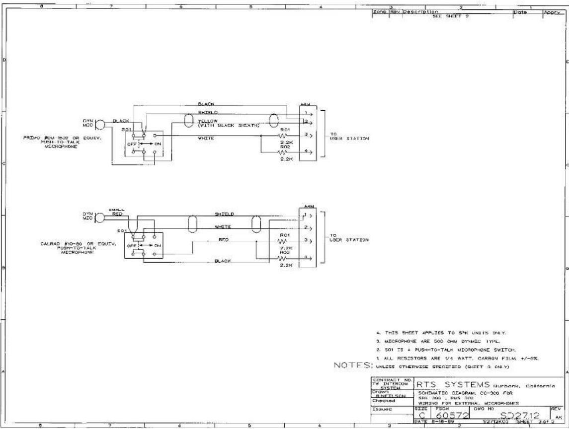

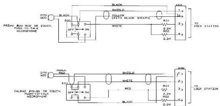
- THIS SHEET APPLIES TO SPK UNITS ONLY.
- MICROPHONE ARE 500 OHM DYNAMIC TYPE.
- 501 IS A PUSH-TO-TALK MICROPHONE SWITCH.
1 ALL RESISTORS ARE 1/4 WATT. CARBON FILM +/-5%
NOTES: UNLESS OTHERWISE SPECIFIED (SHEET 2 ONLY)
| CONTRACT NO. TW INTERCOM SYSTEM | RTS SYSTEMS Burbank, California | |||
| Drawn BENTLEON | SCHEMATIC DIAGRAM. CC-300 FOR SPK 300 , RMS 300 WIRING FOR EXTERNA, MUCORPONES | |||
| Checked | ||||
| ISSUED | SIZE | FSCM | DWG NO | REV |
| C | 60572 | SD2712 | AS | |
| DATE: 8-16-09 | $2712000 SHEET NO. 2 | |||
| 15 | 14 | 13 | 12 | 1 | 10 | 9 | 8 | 7 | 6 | 5 | 4 | 3 | 2 | SHEET | SHEET REVISION STATUS |
| A | A | B | A | AL | A | AL | AA | AY | AN | AI | AI | AM | AL | REV. |
| SINGLE | ITEMS | DATE | APPROVED |
| AC | FEDERAL CMB 400 GB (25" GB) | 12-16-30 | |
| AU | BALANCE CMB 200 GB | 12-16-30 | |
| AV | BALANCE CMB 200 GB | 9-19-30 | |
| AB | ENERGY CMB 175 GB (12" GB) | 12-16-30 | 1.075% |
| AC | ENERGY CMB 200 GB | 9-19-30 | 1.2875% |
| BB | ENERGY CMB 200 GB | 9-19-30 | 1.2875% |
| CA | ENERGY CMB 175 GB (12" GB) | 10-17-30 | |
| CP | COP 12" GB | 8-2-32 | |
| CB | COP 12" GB | 8-2-32 | |
| CA | ENERGY CMB 200 GB | 8-2-32 | |
| CC | ENERGY CMB 200 GB | 8-2-32 | |
| D | ENERGY CMB 200 GB | 8-2-32 | |
| DE | ENERGY CMB 6.7 GB (12" GB) | 9-19-30 | |
| EF | ENERGY CMB 6.7 GB (12" GB) | 9-19-30 | |
| FA | ENERGY CMB 6.7 GB (12" GB) | 9-2-32 | |
| FG | ENERGY CMB 6.7 GB (12" GB) | 9-2-32 | |
| H | ENERGY CMB 6.7 GB (12" GB) | 9-2-32 | |
| IA | ENERGY CMB 6.7 GB (12" GB) | 9-2-32 |
(6) FOR LOCAL POWER OPTION REMOVAL E25 AND IS AND WIRE IS TO PCB AS SHOWN
In MODELS WITH ... OPTION 5.1 IS NOT USED, OLT AND SLEEVE ARE ONOE
④INSTALL JUMPERS IN PLACE OF TS ON RVS-300 SERIES ONLY
INSTALL JIMPER, 12(HTS)2306-5000-00; AND REMOVE NID ON SPE-100 SERIES ONLY
② COGSNECK INC NOT USED ON SPK=300 SERIES OUT AND SLAVE
FOR MODELS WITHOUT LIGHT BOARD, OUT AND SLEEVE WIRE ENDS
M.75: N.FSS OTHERS SPECIF
| ISSUE STRONG STATION | CONTACT NO.###S 320 | RIS SYSTEMS### | ||||
| DATE: 01/01/2024, ###: 01/01/2025 | ||||||
| APPROVED AS: ### | APPROVED | #1 | MEING DIAGNAMSPA/RMS 320 STANDARD, #1 CEFIONCOM POINT CHIN'Y D: ± 0.0000 | |||
| DATE: 01/01/2024, ###: 01/01/2025 | DATE:01/01/2024, ###: 01/01/2025 | #2 | ||||
| APPROVED | ||||||
| DATE: 01/01/2024, ###: 01/01/2025 | APPROVED | #1 | ||||
| DATE: 01/01/2024, ###: 01/01/2025 | DATE:01/01/2024, ###: 01/01/2025 | #2 | ||||
| APPROVED | SCALE: D: ± 0.0000; SHEET OF % | |||||
⑦ A MODELS WITH -L OPTION 52 IS NOT USED, OUT AND SLEEVE WIRE ENDS.
⑥ SA IS A J POSITION TOGGLE SWITCH, C AND X 7211 SPYABE.
⑤ FOR THE 3CH OPTION, MODIFY THE STANDARD CC-200 P.C. BOARD AS FOLLOWED: THE 3 WHOLE (CIRCUIT ONE)
-
- FORCE (CROCKET SIDE) AND 720 (2200) CAT (2500+
ADC 3 JUMPERS (GROUP)
④ INSTALL JIMPER IN PLACE OF 15 ON PAS 300 SERIES ONLY.
INSTALL JUNFER T5(RTS#2306-0006-00) AND REMOVE R15 ON
SPR-300 SERIES ONLY.
(2) DOSELER, INC. 40 USED ON SPX-320 SERIES, CUT AND SLIKING WEC ENIX
② FOR MODULES MINDO' LIGHT BOARD, CUT AND SELL WIRE ENDS.
NOTES: UNLESS OTHERWISE SPECIFIED
| NOT ASSY | ORDER ON | FRESH | CONCEPT TO SERIES 300 | RJS SYSTEMS | ||||
| APPRODALS | DATE | MRING DIAGRAM-SPK/RMS 300 3CH AND 3CH-L OPTIONS | ||||||
| DRAWN | CHECKED | 12 NO. NO | ||||||
| CHECKED | ||||||||
| DRAWN | DATE NO: D160572 | REV NO: WD2712 | REV A. | |||||
| APPLICATION | FULL | W2712L0Z DATE | SHEET 2 OF | |||||
| REVISIONS | |||
| ZUMEREY | DESCRIPTION | DATE | APPROVED |
| SEE SHEET ONE | DATE | ||
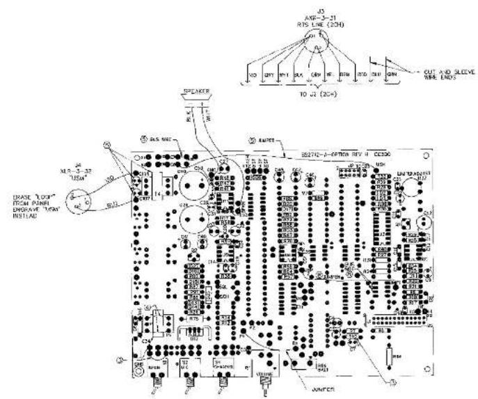
② FOR -USME (S)
A) ADD: TALUMEOQ), C107 AND C108(10/50 ELECT RADIAL), QTY 1 JUMPER, QTY 1 BLS WIRE.
E) BACK PANEL
ELIMINATE "LOOP THRU" WITHS BETWEEN XLR-3-SI (HIS LNL) AND JH
(LOOP THRU).
ERASE TOO AS SHOWN.
☑ CHECK VALUES OF R24 (SHOULD BE 32K), R31 (SHOULD BE 10K).
REMOVE JUMPER (3 PLACES) IF INSTALLED.
- REMOVE RS7 AND W? IF INSTALLED.
(8) OUT TRACE (3 PLACES) ON CIRCUIT SIDE FOR -X, OPTIONAL
©N MODES WITH -I OPTION SS IS NOT USED CUT AND SHEET
WIRE ENDS
④ INSTALL LIMPERS 8 PLAC OF 15 ON 2005 SOD SERIES ONLY.
(3) INSTALL JUMPER T5/RT542X7E 0006-90) AND SEEVE \$15 ON
SPX-30C SERIES ONLY
© GOGENESK MO NOT USED ON SPH-300 SERIES, OUT AND SLVE
MRE ENDS.
① FOR MOZZLES WITHOUT LIGHT BORDS, CUT AND SLIEM WIRE ONDS.
NOTES : UNLESS OTHERWISE SPECIFIED
| USSS ENTERING PROCESSED MAX. 100% MAX. 100% MAX. 100% MINI. 200% MINI. 200% MINI. 300% MINI. 300% MINI. 400% MINI. 400% MINI. 500% MINI. 500% MINI. 600% MINI. 600% MINI. 700% MINI. 700% MINI. 800% MINI. 800% MINI. 900% MINI. 900% MINI. 1000% MINI. 1000% MINI. 1100% MINI. 1100% MINI. 1200% MINI. 1200% MINI. 1300% MINI. 1300% MINI. 1400% MINI. 1400% MINI. 1500% MINI. 1500% MINI. 1600% MINI. 1600% MINI. 1700% MINI. 1700% MINI. 1800% MINI. 1800% MINI. 1900% MINI. 1900% MINI. 2000% MINI. 2000% MINI. 2100% MINI. 2100% MINI. 2200% MINI. 2200% MINI. 2300% MINI. 2300% MINI. 2400% MINI. 2400% MINI. 2500% MINI. 2500% MINI. 2600% MINI. 2600% MINI. 2700% MINI. 2700% MINI. 2800% MINI. 2800% MINI. 2900% MINI. 2900% MINI. 3000% MINI. 3000% MINI. 3100% MINI. 3100% MINI. 3200% MINI. 3200% MINI. 3300% MINI. 3300% MINI. 3400% MINI. 3400% MINI. 3500% MINI. 3500% MINI. 3600% MINI. 3600% MINI. 3700% MINI. 3700% MINI. 3800% MINI. 3800% MINI. 3900% MINI. 3900% MINI. 4000% MINI. 4000% MINI. 4100% MINI. 4100% MINI. 4200% MINI. 4200% MINI. 4300% MINI. 4300% MINI. 4400% MINI. 4400% MINI. 4500% MINI. 4500% MINI. 4600% MINI. 4600% MINI. 4700% MINI. 4700% MINI. 4800% MINI. 4800% MINI. 4900% MINI. 4900% MINI. 5000% MINI. 5000% MINI. 5100% MINI. 5100% MINI. 5200% MINI. 5200% MINI. 5300% MINI. 5300% MINI. 5400% MINI. 5400% MINI. 5500% MINI. 5500% MINI. 5600% MINI. 5600% MINI. 5700% MINI. 5700% MINI. 5800% MINI. 5800% MINI. 5900% MINI. 5900% MINI. 6000% MINI. 6000% MINI. 6100% MINI. 6100% MINI. 6200% MINI. 6200% MINI. 6300% MINI. 6300% MINI. 6400% MINI. 6400% MINI. 6500% MINI. 6500% MINI. 6600% MINI. 6600% MINI. 6700% MINI. 6700% MINI. 6800% MINI. 6800% MINI. 6900% MINI. 6900% MINI. 7000% MINI. 7000% MINI. 7100% MINI. 7100% MINI. 7200% MINI. 7200% MINI. 7300% MINI. 7300% MINI. 7400% MINI. 7400% MINI. 7500% MINI. 7500% MINI. 7600% MINI. 7600% MINI. 7700% MINI. 7700% MINI. 7800% MINI. 7800% MINI. 7900% MINI. 7900% MINI. 8000% MINI. 8000% MINI. 8100% MINI. 8100% MINI. 8200% MINI. 8200% MINI. 8300% MINI. 8300% MINI. 8400% MINI. 8400% MINI. 8500% MINI. 8500% MINI. 8600% MINI. 8600% MINI. 8700% MINI. 8700% MINI. 8800% MINI. 8800% MINI. 8900% MINI. 8900% MINI. 9000% MINI. 9000% MINI. 9100% MINI. 9100% MINI. 9200% MINI. 9200% MINI. 9300% MINI. 9300% MINI. 9400% MINI. 9400% MINI. 9500% MINI. 9500% MINI. 9600% MINI. 9600% MINI. 9700% MINI. 9700% MINI. 9800% MINI. 9800% MINI. 9900% MINI. 9900% MINI. 10000% MINI. 10000% MINI. 11000% MINI. 11000% MINI. 12000% MINI. 12000% MINI. 13000% MINI. 13000% MINI. 14000% MINI. 14000% MINI. 15000% MINI. 15000% MINI. 16000% MINI. 16000% MINI. 17000% MINI. 17000% MINI. 18000% MINI. 18000% MINI. 19000% MINI. 19000% MINI. 20000% MINI. 20000% MINI. 21000% MINI. 21000% MINI. 22000% MINI. 22000% MINI. 23000% MINI. 23000% MINI. 24000% MINI. 24000% MINI. 25000% MINI. 25000% MINI. 26000% MINI. 26000% MINI. 27000% MINI. 27000% MINI. 28000% MINI. 28000% MINI. 29000% MINI. 29000% MINI. 30000% MINI. 30000% MINI. 31000% MINI. 31000% MINI. 32000% MINI. 32000% MINI. 33000% MINI. 33000% MINI. 34000% MINI. 34000% MINI. 35000% MINI. 35000% MINI. 36000% MINI. 36000% MINI. 37000% MINI. 37000% MINI. 38000% MINI. 38000% MINI. 39000% MINI. 39000% MINI. 40000% MINI. 40000% MINI. 41000% MINI. 41000% MINI. 42000% MINI. 42000% MINI. 43000% MINI. 43000% MINI. 44000% MINI. 44000% MINI. 45000% MINI. 45000% MINI. 46000% MINI. 46000% MINI. 47000% MINI. 47000% MINI. 48000% MINI. 48000% MINI. 49000% MINI. 49000% MINI. 50000% MINI. 50000% MINI. 51000% MINI. 51000% MINI. 52000% MINI. 52000% MINI. 53000% MINI. 53000% MINI. 54000% MINI. 54000% MINI. 55000% MINI. 55000% MINI. 56000% MINI. 56000% MINI. 57000% MINI. 57000% MINI. 58000% MINI. 58000% MINI. 59000% MINI. 59000% MINI. 60000% MINI. 60000% MINI. 61000% MINI. 61000% MINI. 62000% MINI. 62000% MINI. 63000% MINI. 63000% MINI. 64000% MINI. 64000% MINI. 65000% MINI. 65000% MINI. 66000% MINI. 66000% MINI. 67000% MINI. 67000% MINI. 68000% MINI. 68000% MINI. 69000% MINI. 69000% MINI. 70000% MINI. 70000% MINI. 71000% MINI. 71000% MINI. 72000% MINI. 72000% MINI. 73000% MINI. 73000% MINI. 74000% MINI. 74000% MINI. 75000% MINI. 75000% MINI. 76000% MINI. 76000% MINI. 77000% MINI. 77000% MINI. 78000% MINI. 78000% MINI. 79000% MINI. 79000% MINI. 80000% MINI. 80000% MINI. 81000% MINI. 81000% MINI. 82000% MINI. 82000% MINI. 83000% MINI. 83000% MINI. 84000% MINI. 84000% MINI. 85000% MINI. 85000% MINI. 86000% MINI. 86000% MINI. 87000% MINI. 87000% MINI. 88000% MINI. 88000% MINI. 89000% MINI. 89000% MINI. 90000% MINI. 90000% MINI. 91000% MINI. 91000% MINI. 92000% MINI. 92000% MINI. 93000% MINI. 93000% MINI. 94000% MINI. 94000% MINI. 95000% MINI. 95000% MINI. 96000% MINI. 96000% MINI. 97000% MINI. 97000% MINI. 98000% MINI. 98000% MINI. 99000% MINI. 99000% MINI. 100000% MINI. 10000 | ||
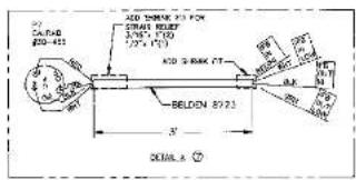
⑦ ASSOCIATE FB OPTION CABLE AS SHOWN IN DETAIL A. P.U2 P7 INTO J7.
6 FOR FB OPTION AND THE FOLLOWING PARTS TO CC-300 : T3. T4 (J9903)
0'05-0108 (10/50V RADIAL ELECTROLYC). 0.5 WIRE LIMITERS BETWEEN
E5, E7 AND ASL.
5 FOR ITB OPTION: (a) ADD 17, CAURA9 #30-456. 6 PIN JACK TO REAR PAINT, MRE AS SHOWN. (b) ADD 53, LOON 08-138, NOMENTARY ACTION SWITCH. MRE AS SHOWN. LENS CAP (WHITE) SHOULD BE ENGRAVED "ITB", TAKES NO LIGHT BULB.
④ INSTALL JUMPERS IN PLACE OF 15 ON INS-300 SERIES ONLY.
⑤ INSTALL JUMPER, TO(RTS#2305-0006-00) AND REMOVE R15 ON SPF-300 SERIES ONLY.
COOSECK INC NOT USED ON SPX-200 SERIES, CUT AND SLATE
① FOR MOODS WITHOUT LIGHT BOARD OR MOMENTARY MIC, CUT AND SLEEVE MHL LMUS
NOTES : UNLESS OTHERWISE SPECIFIED
| UNLESS OPENSIVE SPECIFIC | CONTROL NO. | RIS SYSTEMS | ||||||
| MINI-100% 2000 FOR 2000 AND MINI-100% 2000 FOR 2000 AND MINI-100% | SOLIMES 300 | |||||||
| SPRING LINE | DATE | WIRING DIAGRAMSPK/RMS 300-FB | ||||||
| TOMATO | DATE | J.WELSON | Y-28-92 | |||||
| CHECKED | J.WELSON | Y-30-92 | ||||||
| MATERIAL | DRAWN | J.WELSON | Y-30-92 | |||||
| NOT ASO | ORDER ON | DRAWN | DATE: 06/05, NO. D169572 WD2712 | REV AL | ||||
| APPRODUCTION | DATE:- | WIRING DIAGRAM | FHEET 4 OF | |||||
| STOCK | R/U | DESCRIPTION | DATE | APPROVED |
| SEE SHEET ONE |
- THIS DRAWING SHOWS THE AUX. LISTEN POT SET TO MONITOR
CHANNEL 1 (STANDARD).
(1) RKL CHANDEE FROM SEE TO 10
1.3.1 CHANGES FROM 35% TO 70% FOR -DE OPTION,
(2) KZI COMES FROM ZZR 15 ZZR FOR -DE SP-IGN
②REND, JIMPLCSTOR -DL OP'CN
② HENDY W/ FDR - IX CIPION
② HOVENTARY MC NOT USED ON UNITS WITH CALL LIGHT OPTION (-L)
(1) AND SLEEVE RELI.
(6) OUT TRADES ON CIRCUIT SIDE (3 PLACES)
(5) OUT TRACE ON COMPONENT SIDE (ONE PLACE).
④ INSTALL JUMPERS IN PLACE OF TS ON HMS-300 SERIES ONLY
INSTALL SUMPT, 15(RT56(360-6000-30) AND REMOVE R&D ON
SPK-300 SERIES ONLY
② GOOLED/RECK INC NOT USED ON SPAC RED SLIES, CJT AND SLIVE
MRE END: ① FOR HOURS
(1) FOR ROLLERS WITHOUT LIGHT ROAD, CUT AND SLEEVE ONE ENDS.
NOTES : UNLESS OTHERWISE SPECIFIED
| JAMES CHINESE SPOTATO MAX. 10000000000000000000000000000000000000000000000000000000000000000000000000000000000000000000000000000 | CONTRACT NO. SERIES 300 | RTS SYSTEMS SPRING DIAGRAM SPK/RMS300-3CH-DI1(AB) | |||||
| APPROALS | DATE | ||||||
| DRAWN WELDIN | 10-3-90 | ||||||
| DISCUIT | |||||||
| NEXT ASY | JEDD ON | FROHS | DESCRIPTION | DATE: 2014 D160572 | ORDER No. WD2712 | ||
| APPLICATION | SCALE:- | WD271205.2W | WHIP 5 OF | ||||
| DESCRIPTION | |||||
| DATE | APPROVED | ||||
| AM | ADD: NOTE 13; CHG NOTE 6.ECO # 58672 | 28 FEB 24 | |||
| AK | CHG NOTE '0 SEE ECD | ECO PRAVAN 44 | 5-22-04 | ||
FOR PROGRAM INPUT LEVELS OF
A) + B dB (INDIACAT) AND + 4 dB, USE CIRCUIT SHOWN. R103 (X), R124: R105 (4.7K)
(2) АКЛАНИ ГЛИЧЕСКИЯ В.Н.:
C) - AHP (E10-CPV, C)
(1) - 0.05 (FAL-017, S.2324), DEL-TE R103, REPLACE R104, R105 WITH O QIM RESISTORS.
REMOVE RS7 FOR PROGRAM INPUT (-C) OPTION.
- FOR PROGRAM INPUT (C) OPTION: ADD 5 TO REAR PANEL, W9: 48"
@ 406 JUMPER FOR PROCESAR INPUT - CIRCUIT
② OUT TRACE FOR PROGRAM INPUT (c) TRICTION (CIRCUL-1986)
(2) FOR PROGRESS INVEST. (1) ONION, VOLT, UNITS, AND
(2) 100% of the 31-47 option made IMPER FROM JMP & JMP2 TO US-1 & JMP2
(2) FOR PROGRAM WITH;-6; OPTION: REMOVE JUMPERS AT U3 PINS 5,6 AND
© THE PROGRAM INPUT (C) OPTION: AND C2(1/50), C3(100F), C4(100/100), C5(22F).
CHS AND CH02(10/50), R31 AND R13(47K), R23(150K), R45 & R'02(10K), 351(10CK), R52(22K)
R105, R106, R705 (SEE NOTE 12), 14(42TM018), UX3550 AND R-PIN SOCKET). CHANGE: RT FROM
SINGLE TO DUAL POT. CHARGE R31 VALUE TO 10K
(2) IN MODELS WITH - OPTION SS IS NOT USED. CUT AND SLEEVE
[Unreadable]
④INS 61 JIMPER IN PLACE OF TO CHING 300 SERIES ONLY.
INSTALL JUMPER, TS(RTS#2308-5006-50) AND REMOVE PAE ON
SPK-700 SERIES OHI
② DOGSEVECK MO NOT USED ON SPX 360 SEETS OUT ADO PENG
ARF ENDS
(1) FOR MODELS WITHOUT LIGHT BOARD, O.T. AND SLEEVE WIRE CLOS
HOURS: UNLESS OTHERS SPECIFIED
| MATERIALS | ||||
| ITEMS | DESCRIPTION | SPEC. | RDS SYSTEMS | |
| 1 | 0.5 | 0.5 | 4000 | HARRICK DIAGRAM- |
| 2 | 0.5 | 0.5 | DATE | SPR/RMS 300 PROGRAM INPUT OPTIONS( |
| 3 | 1.00 | 1.00 | 12-10-11 | (CO NOT USE WITH DL) |
| 4 | 2.00 | 2.00 | ||
| 5 | 3.00 | 3.00 | ||
| 6 | 4.00 | 4.00 | ||
| 7 | 5.00 | 5.00 | ||
| 8 | 6.00 | 6.00 | ||
| 9 | 7.00 | 7.00 | ||
| 10 | 8.00 | 8.00 | ||
| 11 | 9.00 | 9.00 | ||
| 12 | 10.00 | 10.00 | ||
| 13 | 11.00 | 11.00 | ||
| 14 | 12.00 | 12.00 | ||
| 15 | 13.00 | 13.00 | ||
| 16 | 14.00 | 14.00 | ||
| 17 | 15.00 | 15.00 | ||
| 18 | 16.00 | 16.00 | ||
| 19 | 17.00 | 17.00 | ||
| 20 | 18.00 | 18.00 | ||
| 21 | 19.00 | 19.00 | ||
| 22 | 20.00 | 20.00 | ||
| 23 | 21.00 | 21.00 | ||
| 24 | 22.00 | 22.00 | ||
| 25 | 23.00 | 23.00 | ||
| 26 | 24.00 | 24.00 | ||
| 27 | 25.00 | 25.00 | ||
| 28 | 26.00 | 26.00 | ||
| 29 | 27.00 | 27.00 | ||
| 30 | 28.00 | 28.00 | ||
| 31 | 29.00 | 29.00 | ||
| 32 | 30.00 | 30.00 | ||
| 33 | 31.00 | 31.00 | ||
| 34 | 32.00 | 32.00 | ||
| 35 | 33.00 | 33.00 | ||
| 36 | 34.00 | 34.00 | ||
| 37 | 35.00 | 35.00 | ||
| 38 | 36.00 | 36.00 | ||
| 39 | 37.00 | 37.00 | ||
| 40 | 38.00 | 38.00 | ||
| 41 | 39.00 | 39.00 | ||
| 42 | 40.00 | 40.00 | ||
| 43 | 41.00 | 41.00 | ||
| 44 | 42.00 | 42.00 | ||
| 45 | 43.00 | 43.00 | ||
| 46 | 44.00 | 44.00 | ||
| 47 | 45.00 | 45.00 | ||
| 48 | 46.00 | 46.00 | ||
| 49 | 47.00 | 47.00 | ||
| 50 | 48.00 | 48.00 | ||
| 51 | 49.00 | 49.00 | ||
| 52 | 50.00 | 50.00 | ||
| 53 | 51.00 | 51.00 | ||
| 54 | 52.00 | 52.00 | ||
| 55 | 53.00 | 53.00 | ||
| 56 | 54.00 | 54.00 | ||
| 57 | 55.00 | 55.00 | ||
| 58 | 56.00 | 56.00 | ||
| 59 | 57.00 | 57.00 | ||
| 60 | 58.00 | 58.00 | ||
| 61 | 59.00 | 59.00 | ||
| 62 | 60.00 | 60.00 | ||
| 63 | 61.00 | 61.00 | ||
| 64 | 62.00 | 62.00 | ||
| 65 | 63.00 | 63.00 | ||
| 66 | 64.00 | 64.00 | ||
| 67 | 65.00 | 65.00 | ||
| 68 | 66.00 | 66.00 | ||
| 69 | 67.00 | 67.00 | ||
| 70 | 68.00 | 68.00 | ||
| 71 | 69.00 | 69.00 | ||
| 72 | 70.00 | 70.00 | ||
| 73 | 71.00 | 71.00 | ||
| 74 | 72.00 | 72.00 | ||
| 75 | 73.00 | 73.00 | ||
| 76 | 74.00 | 74.00 | ||
| 77 | 75.00 | 75.00 | ||
| 78 | 76.00 | 76.00 | ||
| 79 | 77.00 | 77.00 | ||
| 80 | 78.00 | 78.00 | ||
| 81 | 79.00 | 79.00 | ||
| 82 | 80.00 | 80.00 | ||
| 83 | 81.00 | 81.00 | ||
| 84 | 82.00 | 82.00 | ||
| 85 | 83.00 | 83.00 | ||
| 86 | 84.00 | 84.00 | ||
| 87 | 85.00 | 85.00 | ||
| 88 | 86.00 | 86.00 | ||
| 89 | 87.00 | 87.00 | ||
| 90 | 88.00 | 88.00 | ||
| 91 | 89.00 | 89.00 | ||
| 92 | 90.00 | 90.00 | ||
| 93 | 91.00 | 91.00 | ||
| 94 | 92.00 | 92.00 | ||
| 95 | 93.00 | 93.00 | ||
| 96 | 94.00 | 94.00 | ||
| 97 | 95.00 | 95.00 | ||
| 98 | 96.00 | 96.00 | ||
| 99 | 97.00 | 97.00 | ||
| 100 | 98.00 | 98.00 | ||
| REVISIONS | ||||
| ZONE REL. | DESCR PWRN | DATE | APPROVED | |
| AH | ADD: NOIE 10X CHS: NOIE R.EOD # 596/2 | 28 FDR 94 | 104 | |
| AH | CHS: NOIE TO SEL: EOD.TOO #53125 | ### | S 23 94 | ### |
① FOR PROGRAM INPUT LEVELS OF
A) -0.28 (EROMCAST) AND -1dB, USE CIRCUIT SHOWN. RIOS (1K), RIO4 & RIOS (<7K)
(STANDARD CONSTRUCTION)
B) 0 dB DE.ETE R101.
-10 (FACTORY STANDARD); DELETE R103, REPLACE R104 AND R105
WITH O OHM RESISTORS
② IN MODES WITH -1 OPTION, \$3 IS NOT USED, OUT AND SLEEVE WIRE ENDS.
- FOR LADD INSTRUMENT ON PHECHOC-900 (CHIN, LISTEN, PRICE-IN, NEUT, AND LISTED)
S. FOR EXCEL INFORMATION SEE DRAWING F36145
(2) FOR UNSHANCED INC. DEPT ON NEW PROGRAM APRIL (OPTION 5, PRESENT: NO. E10LM9003)
CHS AND CHS (10/F/SON ELECT), 24 AND RED WIRE JUMPER (60 TO USM) ON BOTTOM SIDE OF BOARD, 22 AND BUS MIRE (63 TO LT) ON BOTTOM SIDE OF BOARD. USE IN (LOOP CONN) WITH TWO 24 AND WIRE JUMPERS (JH-2 TO CHS AND JA-3 TO CHD). FOR THE USM CONNECTOR (JH) ERASE "LOOP/EXT" AND ADD LABEL "USM" (SEE NOTE 8).
- FOR GROUP ON OF I/O, RIO, 700 (DUAL LISTON OPTION: PERSPECT ADD TAVOUSER 427(016)), CHO, 700 (TOF, 70V ELEC), F22 & ROK(4X), RIO2(9X), RIO3, RIO4, RIO5 (SEE ONE TO), JOS, 700 (ACR, POT, THE POM VOL, POT IS ADRUED IN THE FRONT PANEL) WILL THERE 24 AWG WIRE JUMPERS(CW of POW VOL, IL 8), OCN of POM VOL, POT TO SIZE, AND # OF PUM VOL POT TO NIPPER (OF RIO) THE TOP SIDE OF THE BOARD, ADD 22 AWG BUS WIRE (E7 TO ASL, RIO3 TO RIO5) ON THE TOP SIDE OF THE BOARD, ADD 22 AWG BUS WIRE (THE TOP SIDE OF THE BOARD) WITH THE 24 AWG WIRE (E7 TO ASL, RIO3 TO RIO5) TO CIO AND JOS (3 - 3 TO (-)) ON THE TOP SIDE OF THE BOARD, ADD JUMPERS FROM CITY(-) RIO TO E2 & FLOW (CIO(-)) PAD TO £1 (80" WIDE OF BOARD)
FOR DUAL JISTEN OPTION: OUT ONE TRACE (WS TO RIS) ON THE TOP SIDE OF THE BOARD, CUT ITEMS TRADES (US 3 TO Q4, J1 1 TO MS, E10 TO E9) ON THE BOTTOM SIDE OF THE BOARD. REMOVE RS7 AND W7. REMOVE THREE JUMERS (JMP1 TO MP2, J3 5 TO U3 6, AND US 6 TO US 7) ON BOTTOM SIDE OF THE BOARD. CHANGE F24 TO 22K,1/4K,5% AND J81 TO 80K,1/4K,5% ADD DUAL JISTEN OPTION COMPONENTS PER PARTS LIST 903035570).
④ ON ENSO3 UNITS ONLY TRANSFORMER TS IS NOT INSTA FE, ATO TWO 24 AND RED WIRE
JUMPERS IN PLACE OF TO ON BUTTON SIZE OF THE BOARD AS SHOWN.
(2) ON EXC.100 WHITE ONLY. METALL JUMPER ACROSS ST. METALL TRANSFORMER TEFFE
(2305000800), AND REMOVE RESISTOR RIS.
② GOODENED, MIC NOT USED ON 5PK-300 SERIES, OUT AND SLEEP
ARE ENDS
① FOR MODELS WITHOUT LIGHT BOARD, OUT AND SLEEVE WIRE ENDS
NOTES: UNLESS OTHERWISE SPECIFIED
| DATE: OVERNOLOGY GROUP | CONTACT NO. | SERCS 300 | RTS SYSTEMS | |||||
| DATE: 2/15/2017 | APPROALS | DATE | ||||||
| DATE: 2/15/2017 | DRAWN | PICKDOWN | (12-10-96) | AMERIC DIAGRAMS--SPK/RANS 300--RUMAL LISTEN--C (PROGRAM INPUT) -S (USMA), -BCL | ||||
| DATE: 2/15/2017 | CHECKED | |||||||
| NEXT DATE: JULIO 2017 | FRESH | DESCRIPTION NO.: | DESCRIPTION NO.: | DESCRIPTION NO.: | ||||
| APPLICATION: | —— | —— | DW2712 | |||||
INSTALL QTY, 1 NUMPER AND QTY, 2 SUS USED FOR
AND ONE
①IN MODELS WITH -L OPTON, 53 IS NOT USED. CU AND SUTIVE MRF ENDS.
(2) FOR RAC COTORS (40, 15 (Q18-4-3)) IN THE BACK PANEL. THIS INFORMATION INPUT
AND: LRF. "REATE" CABBET WEL ID. 10-16001 PAVIL AS SHOWN.
(2) 50% - 100% (3)
c) ADD. 14/19/2017, CTRZ AMF. CHINCO/50 ELECTRICAL QTY 1 JUNEER, QTY 1 BUS WIRE.
B. BACK
E. PRIVATE LOOP THEM" MRS BETWEEN 813-3-31 (RTS LPE) AND 14 (LOOP THRU).
"FROM BACK PANEL ENGRIVE USA" INSTALLED. WIRE, IN AS SHOWN.
⑩ N MODELS WITH -L OPTION, \$3 IS NOT USED. OUT AND SLEET OF WIRE FINDS.
② FOR UNITS WITH -3CH (A) OPTION ONLY
a) S4 IS A 3-POSITION SWITCH (RTS#1903-0059-00)
a) R90(100K) AND CAT(22JF/50%) ARE ADDED
B. THIS DRAWING DOES NOT APPLY TO UNITS WHICH ALSO INCLUDE THE -UL (B) OPTION.
⑦ MAKE UP A SET TONG CABLE AS SHOWN IN DETAIL A. MAKE WIFE LABELS "182-1".
"1B2-2" AND "1B2-3" USING Ept HELVE 104 LIGHT, BLX ON C CONNECTOR INTO THE "1B2" CONNECTOR ON THE PAGI PANEL
(3) MATRUS LOWER, 15 (HISPSIZE GOOD SO), AND REMOVE THIS ON SFR 300 SERIES ONLY
(2) GOODENCK RIC NO USED ON SPR-302 SERIES, CAT AHD SCENE
THE OROOLS WITHOUT LIGHT BOARD, CJT AND SHEET WIRE ENDS.
NOTES: UNLESS OTHERWISE SPECIFIED
VIRLESS CHEMICAL SPECIFIED CONTRACT NO. SERIES 320 BTS SYSTEM
| SINER 500 | R.S. 37823 | BASSE CAPACAO, LBS | |||||
| ORDER NAME: | DESCRIPTIONS | DATE: | DRAWN BY: | ||||
| ITEMS NUMBER: | DRAWN NAME: | CHECKED BY: | DRAWN BY: | ||||
| APPROVED BY: | APPROVED BY: | APPROVED BY: | DATE: | APPROVED BY: | |||
| REV. ASBY | USED ON | DRAWN | DRAWN | DRAWN BY: D:60572 | DW2712 | ||
| APPLICATION | SCALE:- | #2712/39/WS | |||||
| REVISIONS | ||||
| 2010 | REV. | DESCRIPTION | DATE | APPROVED |
| SEE SHEET ONE | ||||
☑ CHECK VALUES OF R24 (S=0U.0 BE 22K), R31 (SHOULD BE 10K).
DO REMOVE JUMPER (3 PLACES) F INSTALLED.
- ALCOE NO, NO P, P INSTALLED.
(8)2.1 IMAGE (3 PAGES) 5D CIRCUIT SIDE FOR -DE OPTION. (7)2.1 IMAGE ON CHRONOMI SIDE FTR -PL ORTOY
(1) SET PRICE OF COMPONENT SIZE FOR -32 (HIGH),
B. USE CLS305 STOP LD WITH DUAL LISTEN OPTION PARTS (3600-3687-60).
(5) IR MODELS WITH -L OPTION SS IS NOT USED. OUT AND SELF, SHU DRY WIRE WIRE 1ST OPEN TO PIN A OF DEF CONNECTOR AND CHINE CRY WIRE
④INSTALL LHPERS IN PLUCT OF 75 ON BVS-700 SERIES ONLY
③INSTALL JUMPER, 10K158236-006-50) AND REMIME RIS ON
SFX=300 SERIES ONLY.
⑦ GOCSECHECK MIC NOT USED ON EPK-300 SERIES, CUT AND SLEEVE
WIRE ENDS
① FOR MODELS WITHOUT LIGHT BOARD, CUT AND SHEET WIRE ONDS.
NOTES UNLESS OTHERWISE SPECIFIED
| DESCRIPTION NO. | DESCRIPTION 300 | RTS SYSTEMS | |
| SERIES 300 | WIRING DIAGRAM | ||
| APPROVED BY: | APPROVED DATE | SPK/RMS300-DL(B)-NS6(V), -DL(B)-L-V56(V) | |
| MINI-120 | MINI-120 | ||
| MINI-120 | MINI-120 | ||
| MINI-120 | MINI-120 | ||
| NEXT KEY | USED ON | DONE | DATE: 04/07/20 WID2712 |
| FRESH | FULL | SCALE:- WD71210.2MG | |
| APPLICATION | |||
FOR UKSWITCHED BALMIGLED INC OUT(S) OPTION WITH PROGRAM INPUT OPTION.S PRESENT: 4. ADD.TV(ABCB3), C15, AND C106(DB/202 ELECT).
⑤ ACD #24 AWG RED JUMPER FROM ES TO USN, #22 AWG BJS WRE JUMPER FROM
(3) 18.2007 CONVOCING IE WTR 500-2007 CONVOCING (DATE: 2007/04/17)
(2) 34 LOOP CONNECTION IS USED FOR USA PROCESSED SLKSCREENING AND ADD LABE. "JSV", WIRE AS SHOWN.
⑤ IN MODELS MIN -L OPTION, SS IS NOT USED. CUT AND SLEEVE IMPRE ENDS.
④ ON RMS300 UNITS ONLY. TRANSFORMER TS IS NOT INSTALLED AND FWD 24 AWG RED WIRE
JUMBERS IN CHADS OF TO OIL COTTON OUC OF THE BOARD AS SHOWN.
① ON SPK300 UN'S ONLY: INSTALL JUMPER ACROSS ST, INSTALL TRANSFORMER TS(RTS
(2305009600), AND REMOVE RESISTOR RIS
② GOOSHOCK MIC NOT USED ON 5WK-300 SERIES, CUT AND SLEEVE WIRE ENDS.
① FOR MODELS WITHOUT LIGHT BOARD, OUT AND SHEET WIRE ENDS.
2014年1月1日
NOTES = UNLESS CHINESE SPECIFIED
| APLICATION | DATA NAME: | DATA ID: | ||||
| SINEMA 300 | R/S SYSTEMS | |||||
| SINEMA 300 | SINEMA 300 | |||||
| APPROVED | JAL | |||||
| MINI | 12 | |||||
| MAX | 12 | |||||
| MINI | 12 | |||||
| -10.00 | -10.00 | |||||
| MAX | 12 | |||||
| -10.00 | -10.00 | |||||
| HOT ASSY | USED ON | ORDER | CHECKED | SIZE FROM NO. | BING NO. | |
| D160572 | WJ2712 | |||||
| APPLICATION | TITLE | TITLE | TITLE OF | |||
'5. CONNECT F1 TO B6 AND T2 TO L8
- CONNECT J3 AND J4 AS SHOWN.
③ SHORT 15 AND ET AND ASL WITH BUS WIRE FOR 2 WIRE.
EXPLANISED OFFICE
② FCR LOCAL POWER OPTIONAL REMOVE 208, AND JE TO BE
P. 25 约
41 CHECK VALUES OF R24 (SHOULD BE 22K), H3 (SHOULD BL 10K).
⑩ REMOVE JUMPER (3 PLACES) IF INSTALLED
- REMOUNT R57 AND W7 IF INSTALLED.
(8) CUT TRACE (3 PLACES) ON CIRCUIT SIDE FOR -CL OPTION
OUT INJECT ON COMPONENT SIDE FOR -DL OPTION
- USE CC300 STuffed WITH DUN LISTN OPTION PARTS (0030, 2982, 00)
⑤ N 40015 WTH = (820% S) IS VOLUED OUT 613 SEES
MRC ENDS
© NIKHI THURDS IN PLACE OF TS ON THE 300 CENTER ONLY.
© INSTALL JUNFER. TS(2TS42.508-3005-00) AND REMOPE PAS OF
EPM 300 SERIES ONLY
② DOSENFOX INC. NOT USED ON SPX-300 SERIES, CUT AND SELLV
WRF ENDS
①FOR MODELS WITHOUT LIGHT BOARD, CUT AND SLEEVE WIRE ENDS.
NOTES : UNLESS OTHERWISE SPECIFIED
| TITLES OF 120000000000000000000000000000000000000000000000000000000000000000000000000000000000000000000000000000 | CONTROL NO. | SERIAL 300 | RTS SYSTEMS | RIP RING DIAGRAM SPK/RMS300-DL(B)-1P(Γ), -2WB(-) -L | ||||||
| APPROVALS | DATE | |||||||||
| 178 | 1.00 | 1.00 | 1.00 | DNAM | 9-33-02 | |||||
| 178 | 1.00 | 1.00 | 1.00 | DNAM | 9-33-02 | |||||
| 3652.0% | 3652.0% | 3652.0% | 3652.0% | 3652.0% | ||||||
| APPROVALS | SCALE= | WDZ2120000000000000000000000000000000000000000000000000000000000000000000000000000000000000000000000000 | ||||||||
| ITEMS | ||||
| ZONE | R/Y | DESCRIPTION | DATE | APPROVED |
| A | RELEASE TO MFG, ECG, STON | KB | ||
| B | ADO: NOTE 15; CHG, NOTE 6, FCG # 58672 | 28 FIB 94 | BK | |
| C | CHG NOTE 15 SEE CCC ECG #01128 | 5-23-94 | K | |
15 FOR PROGRAM INPUT LEVELS OF
A) +8 dB (BROADCAST) AND +4 dB. USE ORCUT AS SHOWN. RIO21 (IK), R104, & R105 (4.7)
(STANDARD CONFIGURATION)
C. 10 μB (FACTORY STANDARD): DELET, 2103, DELETT, 2104 & P175
WITH OCH RESISTORS
(4) S4 IS A 3 POSITION TOSSUE SWITCH, C AND K 7211 SPYAGE
13.5% THE VCH CATCH MONEY THE STANDARD CC 300 D.C 20420
AS FOLLOWS: CUT 1 TRACE (CIRCUIT SIDE)
ADD 190 (220K), C47 (22M /50V)
① FOR PROGRAM INPUT(-0) DETOU REAVES INSTRUCTIONS AT 1/3 APR 5.6 AND
(2) 1.0000000000000000000000000000000000000000000000000000000
FOR AMOUNT INPUT(-CY OF TUN, ALS C2.1/50), C1L(100pF, C18,101/-131), C28,29pF, C16,47,62(10/60), (CL-301-311) (H2O2P4, 400+ mation), (H1(100pF, pmlan))
101 AND 132(10,50), R1 AND R1347K), R23(15K), R9 & R102(10K), R5R102K), R52(22K), S101, S101, S105 (SEE NOTE (5), TA'4234018), UX3558 (4W, X-UN WICKL), CHAND, IL, LIX
SINGLE TO DEAL POT. CHANGE RSI VALUE TO 202
© IN MODES WITH - OPTION ST IS NOT USED OUT AND SHEET
WIRE ENDS.
④ INSTALL JUMPERS IN PLACE OF TS ON BUS 320 SERIES (OK)
② INSTALL JUMPER, TSRTS42306-0008-00 AND REMOVE R'S ON
TFC-203 SERIES QIL1
② GOOSECHECK 91C NO" USED OR SPX-300 SERIES OUT AND SLEEVE
WISC CHOS
① FOR MODELS WITHOUT LIGHT BOARD, CUT AND SLEEVE WRC ENDS
NOTES: UNLESS OTHERWISE SPECIFIED
| LED OFFICE CONTROL TOLERS ON 2000/2001/2002/2003/2004/2005/2006/2007/2008/2009/2010/2011/2012/2013/2014/2015/2016/2017/2018/2019/2020/2021/2022/2023/2024/2025/2026/2027/2028/2029/2030/2031/2032/2033/2034/2035/2036/2037/2038/2039/2040/2041/2042/2043/2044/2045/2046/2047/2048/2049/2050/2051/2052/2053/2054/2055/2056/2057/2058/2059/2060/2061/2062/2063/2064/2065/2066/2067/2068/2069/2070/2071/2072/2073/2074/2075/2076/2077/2078/2079/2080/2081/2082/2083/2084/2085/2086/2087/2088/2089/2090/2091/2092/2093/2094/2095/2096/2097/2098/2099/2100/2101/2102/2103/2104/2105/2106/2107/2108/2109/2110/2111/2112/2113/2114/2115/2116/2117/2118/2119/2120/2121/2122/2123/2124/2125/2126/2127/2128/2129/2130/2131/2132/2133/2134/2135/2136/2137/2138/2139/2140/2141/2142/2143/2144/2145/2146/2147/2148/2149/2150/2151/2152/2153/2154/2155/2156/2157/2158/2159/2160/2161/2162/2163/2164/2165/2166/2167/2168/2169/2170/2171/2172/2173/2174/2175/2176/2177/2178/2179/2180/2181/2182/2183/2184/2185/2186/2187/2188/2189/2190/2191/2192/2193/2194/2195/2196/2197/2198/2199/2200/2201/2202/2203/2204/2205/2206/2207/2208/2209/2210/2211/2212/2213/2214/2215/2216/2217/2218/2219/2220/2221/2222/2223/2224/2225/2226/2227/2228/2229/2230/2231/2232/2233/2234/2235/2236/2237/2238/2239/2240/2241/2242/2243/2244/2245/2246/2247/2248/2249/2250/2251/2252/2253/2254/2255/2256/2257/2258/2259/2260/2261/2262/2263/2264/2265/2266/2267/2268/2269/2270/2271/2272/2273/2274/2275/2276/2277/2278/2279/2280/2281/2282/2283/2284/2285/2286/2287/2288/2289/2290/2291/2292/2293/2294/2295/2296/2297/2298/2299/2300/2301/2302/2303/2304/2305/2306/2307/2308/2309/2310/2311/2312/2313/2314/2315/2316/2317/2318/2319/2320/2321/2322/2323/2324/2325/2326/2327/2328/2329/2330/2331/2332/2333/2334/2335/2336/2337/2338/2339/2340/2341/2342/2343/2344/2345/2346/2347/2348/2349/2350/2351/2352/2353/2354/2355/2356/2357/2358/2359/2360/2361/2362/2363/2364/2365/2366/2367/2368/2369/2370/2371/2372/2373/2374/2375/2376/2377/2378/2379/2380/2381/2382/2383/2384/2385/2386/2387/2388/2389/2390/2391/2392/2393/2394/2395/2396/2397/2398/2399/2400/2401/2402/2403/2404/2405/2406/2407/2408/2409/2410/2411/2412/2413/2414/2415/2416/2417/2418/2419/2420/2421/2422/2423/2424/2425/2426/2427/2428/2429/2430/2431/2432/2433/2434/2435/2436/2437/2438/2439/2440/2441/2442/2443/2444/2445/2446/2447/2448/2449/2450/2451/2452/2453/2454/2455/2456/2457/2458/2459/2460/2461/2462/2463/2464/2465/2466/2467/2468/2469/2470/2471/2472/2473/2474/2475/2476/2477/2478/2479/2480/2481/2482/2483/2484/2485/2486/2487/2488/2489/2490/2491/2492/2493/2494/2495/2496/2497/2498/2499/2500/2501/2502/2503/2504/2505/2506/2507/2508/2509/2510/2511/2512/2513/2514/2515/2516/2517/2518/2519/2520/2521/2522/2523/2524/2525/2526/2527/2528/2529/2530/2531/2532/2533/2534/2535/2536/2537/2538/2539/2540/2541/2542/2543/2544/2545/2546/2547/2548/2549/2550/2551/2552/2553/2554/2555/2556/2557/2558/2559/2560/2561/2562/2563/2564/2565/2566/2567/2568/2569/2570/2571/2572/2573/2574/2575/2576/2577/2578/2579/2580/2581/2582/2583/2584/2585/2586/2587/2588/2589/2590/2591/2592/2593/2594/2595/2596/2597/2598/2599/2600/2601/2602/2603/2604/2605/2606/2607/2608/2609/2610/2611/2612/2613/2614/2615/2616/2617/2618/2619/2620/2621/2622/2623/2624/2625/2626/2627/2628/2629/2630/2631/2632/2633/2634/2635/2636/2637/2638/2639/2640/2641/2642/2643/2644/2645/2646/2647/2648/2649/2650/2651/2652/2653/2654/2655/2656/2657/2658/2659/2660/2661/2662/2663/2664/2665/2666/2667/2668/2669/2670/2671/2672/2673/2674/2675/2676/2677/2678/2679/2680/2681/2682/2683/2684/2685/2686/2687/2688/2689/2690/2691/2692/2693/2694/2695/2696/2697/2698/2699/2700/2701/2702/2703/2704/2705/2706/2707/2708/2709/2710/2711/2712/2713/2714/2715/2716/2717/2718/2719/2720/2721/2722/2723/2724/2725/2726/2727/2728/2729/2730/2731/2732/2733/2734/2735/2736/2737/2738/2739/2740/2741/2742/2743/2744/2745/2746/2747/2748/2749/2750/2751/2752/2753/2754/2755/2756/2757/2758/2759/2760/2761/2762/2763/2764/2765/2766/2767/2768/2769/2770/2771/2772/2773/2774/2775/2776/2777/2778/2779/2780/2781/2782/2783/2784/2785/2786/2787/2788/2789/2790/2791/2792/2793/2794/2795/2796/2797/2798/2799/2800/2801/2802/2803/2804/2805/2806/2807/2808/2809/2810/2811/2812/2813/2814/2815/2816/2817/2818/2819/2820/2821/2822/2823/2824/2825/2826/2827/2828/2829/2830/2831/2832/2833/2834/2835/2836/2837/2838/2839/2840/2841/2842/2843/2844/2845/2846/2847/2848/2849/2850/2851/2852/2853/2854/2855/2856/2857/2858/2859/2860/2861/2862/2863/2864/2865/2866/2867/2868/2869/2870/2871/2872/2873/2874/2875/2876/2877/2878/2879/2880/2881/2882/2883/2884/2885/2886/2887/2888/2889/2890/2891/2892/2893/2894/2895/2896/2897/2898/2899/2900/ |
④ ADD BLUSS WIRE, PIN 4 TO PIN 5 ON DCF CONNECTOR FOR -Y OPTION.
13. THIS DRAWING SHOWS THE AUX LISTEN POT SET TO MONITOR
CHANNEL 1 (STANDARD).
② REMOVE RS7 FOR -CL OPTION.
① SET CHANGED FROM 30% TO FOR -DC OPTION.
224 CHANKES FROM 220K TO 224 FOR -OL OPTION
(9) REMOVE JUMPORS FOR -OL OPTION
(8) REMOVE W7 FOR -CL OPTION.
⑦ komunikasy, ME NOT USED OR UNITS WITH CALL LOAD OPTION (-)
OUT AND SLEEVE WIRE ENOS.
⑥ CUT TRADES ON CIRCUIT SIDE (3 PLACES).
© 2011 TRASIL ON COMMISSION SET (ISM E:40)
④ INSTALL JUPPERS IN PLACE OF TS ON RNS=200 SERIES ONLY.
③ INSTALL J-MPER, TS(RTS#2306-0088-00) AND REMOVE R15 ON
CPX 300 SERIES ONLY
(2) GOOSENECK MIC NOT USED ON 3PK-300 SERIES, CUT AND SLIEVE
WRC DMS
①FOR MODELS WITHOUT LIGHT BOARD, OUT AND SLEEVE WIRE ENDS.
NOTES: UNLESS OTHERWISE SPECIFIED
| DATE: 2015-03-01 | ORDER BY:### ### | DESCRIPTION:### SERIES 300 | RTS SYSTEMS### ### ### ### | |||
| APPRODNS | DATE | SPK/RMS300-3CH,CLXLG(ABV) | ||||
| DATE: 2015-03-01 | ORDER BY:### ### | DRAWN### | 2.75 M2 | |||
| CHECKED### | 2.75 M2 | |||||
| NEXT ASAY | TITLE ON | 7-DEC-14 | DRAWN### | 2.75 M2 | DW2712 | |
| APPLICATION | DATE | W77-2014DWG | FHEET 14 | |||
- COPYRIGHT NOTICE
- WARRANTY NOTICE
- CUSTOMER SUPPORT
- RETURN SHIPPING INSTRUCTIONS
- DESCRIPTION
- Operational Controls
- Connection, Inputs and Outputs
- Introduction
- CURRENT SOURCE
- MECHANICAL INSTALLATION
- Headset Requirements
- ELECTRICAL
- Power
- Signal
- Crosstalk Control
- USER STATION CONNECTIONS
- Moisture / Contamination Protection
- Hum Prevention
- Operating Controls
- Adjust the Sidetone
- EN5541 - Installation, Local Power Option, RMS300 and SPK300L
- Model SPK300L
- ADD JUMPER FOR PROGRAM INPUT(-C) OPTION:
- CUT TRADE FOR PROGRAM INPUT (-C) OPTION (CIRCUIT SIDE)
- FOR PROGRAM INPUT(-C) OPTION: ADD MODE, SAMPLE HIGH, MPJ & MPJ TO US-1 & MPJ2.
- FOR PROGRAM INPUT(-C) OPTION: REMOVE JUMPER AT U3 PINS 5.6 AND 2.
- FOR PROGRAM INPUT(-C) OPTION: ADD OZL/1/30, CC(10x47, O18/30V/1/30), CC(20x47),
- IN MODE'S WITH L OPTION 53 IS NOT USED, CUT AND SILVEC
- INSTALL AMPERS IN PLACE OF TS ON RUS 320 SERIES ON >
- INSTALL JUMPER, IFR(16/200-300-30) AND REMOVE R/S ON
- GOODCHECK INC NOT USED ON SRE-300 SERIES OUT AND SURVE
- FOR VOUTS IN MOLT LIGHT BOARD, CUT AND SURVE WRC END.
Brand : RTS
Model : SPK-300L
Category : Intercom