
2AW6000DA - Air Conditioning ARCTIC WIND - Free user manual and instructions
Find the device manual for free 2AW6000DA ARCTIC WIND in PDF.

| Product Type | Portable Air Conditioner |
| Model Number | 2AW6000DA |
| Brand | ARCTIC WIND |
| Cooling Capacity | 8,000 BTU/h |
| Power Supply | 115V ~ 60Hz |
| Power Consumption | 1,200 W |
| Airflow Rate | 250 CFM |
| Dehumidification Capacity | 1.5 L/h |
| Dimensions (W x D x H) | 18.5 x 16.9 x 30.7 in (47 x 43 x 78 cm) |
| Net Weight | 55.1 lb (25 kg) |
| Refrigerant | R410A |
| Noise Level (Low/High) | 52 / 56 dB(A) |
| Operating Modes | Cool, Fan, Dehumidify |
| Fan Speeds | 3 (Low, Medium, High) |
| Timer Range | 1 to 24 hours |
| Remote Control | Included (Battery operated) |
| Filter Type | Washable mesh filter |
| Maintenance | Clean filter every 2 weeks; drain condensate as needed |
| Safety Features | Overheat protection, tip-over switch |
| Spare Parts Available | Remote control, filter, drain hose |
| Repairability Index | 8/10 (common parts, easy access) |
Frequently Asked Questions - 2AW6000DA ARCTIC WIND
User questions about 2AW6000DA ARCTIC WIND
0 question about this device. Answer the ones you know or ask your own.
Ask a new question about this device
Download the instructions for your Air Conditioning in PDF format for free! Find your manual 2AW6000DA - ARCTIC WIND and take your electronic device back in hand. On this page are published all the documents necessary for the use of your device. 2AW6000DA by ARCTIC WIND.
USER MANUAL 2AW6000DA ARCTIC WIND
natural_image
Top-down view of a white rectangular fence with two vertical bars and a central rectangular object (no text or symbols visible)
natural_image
Front view of a white rectangular ventilation grille with a central component (no text or symbols visible)
natural_image
Close-up of parallel black striped fabric strips on a white background (no text or symbols)CONONSSUUMMEERR P PRRODODUCUCTT I
For your own records, please attach a copy of your sales receipt to this manual and complete the following:
Model Number: ____
Serial Number: ____
Purchase Date: ____
Store Purchased: ____
Installation Date: ____
Installation Co.: ____
Installer Name: ____
Installer Phone No.:
TABLE OF CONTENTS
INTRODUCTION TO REFRIGERANTS R32 ....1
IMPORTANT SAFETY INSTRUCTIONS....2
ELECTRICAL REQUIREMENTS 3
INSTALLATION HARDWARE ....4
INSTALLATION & ASSEMBLY INSTRUCTIONS 5
USING YOUR AIR CONDITIONER ....10
USING YOUR REMOTE CONTROL ....12
CARE AND MAINTENANCE ....13
TROUBLESHOOTING 14
INTRODUCTION TO REFRIGERANTS R32
The refrigerants used for air conditioners are environmentally friendly hydrocarbons R32. This kind of erant is combustible and odorless. Moreover, it can burn and explode under certain condition. However, there will be no risk of burning and explosion if you comply with the following table to install your air conditioner in a room with an appropriate area and use it correctly.
Compared with ordinary refrigerants, Refrigerant R32 is environmentally friendly and does not destroy the ozone sphere and its value of greenhouse effect is also very low.
Room area requests for air conditioner with Refrigerant R32
| Refrigerant | Capacity(Btu) | Room Area |
| R32 | ≤slant 9K | Above 4m^2 |
| ≤slant 12K | Above 4m^2 | |
| ≤slant 18K | Above 15m^2 | |
| ≤slant 24K | Above 25m^2 |

Warnings
- Please read the manual before installation, using, maintenance.
- Do not use means to accelerate the defrosting process or to clean, other than those recommended by the manufacturer.
- Do not pierce or burn the appliance.
● The appliance shall be stored in a room without continuously operating sources (for example: open flames, an operating ignition gas appliance or an operating electric heater.) - Please contact the nearest after-sale service center when maintenance is necessary. At the time of maintenance, the maintenance personnel must strictly comply with the Operation Manual provided by the corresponding manufacturer and any non-professional is prohibited to maintain the air conditioner.
● The handling, installation, storage, servicing and disposal must comply with the provisions of gas-related national laws and regulations, and also national wiring regulation. - It is necessary to clear away the refrigerant in the system when maintaining or scrapping an air conditioner. Be aware that refrigerants may not contain an odor.
This appliance is not intended for use by persons (including children) with reduced physical, sensory or mental capabilities, or supervision or instruction concerning use of the appliance by a person responsible for their safety.
Children should be supervised to ensure that they do not play with the appliance.
Unit operation limits: Outdoor side 61\~110°F, 80%RH; indoor side 61\~90°F, 80%RH.


IMPORTANT SAFETY INSTRUCTIONS (CONT.)
Before installing and using your air conditioner, please read this owner's manual carefully. Store this manual in a safe place for future reference. Your safety and the safety of others is very important to us. Please pay attention to all safety messages outlined in this owner's manual.
WARNING: To reduce the risk of fire, electrical shock or injury when using your air conditioner, follow the basic precautions below:
- Plug into a grounded 3 prong outle t.
- Do Not remove the ground prong.
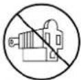
- Do Not use a plug adapter.

- Do Not use an extension cord.
- Unplug the air conditioner before any maintenance.
- Use two or more people to move and install the air conditioner.

This is a safety alert symbol.
This symbol alerts you to potential hazards that can harm you or others or even cause death.
All safety messages will directly follow the safety alert symbol and/or the words
"DANGER" or "WARNING".
! DANGER
WARNING
Failure to immediately follow these instructions may cause serious injury or even death.
All Safety messages alert you of potential hazards, how to reduce the chance of injury, and what can happen if instructions are not followed correctly.
FCC Caution.
This device complies with part 15 of the FCC Rules. Operation is subject to the following two conditions: (1) This device may not cause harmful interference, and (2) this device must accept any interference received, including interference that may cause undesired operation.
Any Changes or modifications not expressly approved by the party responsible for compliance could void the user's authority to operate the equipment.
ELECTRICAL REQUIREMENTS
WARNING

Electrical Shock Hazard
Plug into a grounded 3 prong outlet.
Do Not remove the ground prong.
Do Not use an adapter.
Do Not use an extension cord.
Failure to follow these instructions can
result in electrical shock, fire, or even death.

15A-115V
The electrical ratings for your air conditioner are listed on the model and serial number label located on the front left side of the unit (when facing the front).
Specific electrical requirements are listed in the chart below. Follow the requirements below for the type of plug on the power supply cord.
Wiring Requirements
Power Supply Cord
• 115 volt (103 min.—127 max)
0-8 amps
• 10-amp time-delay fuse or circuit breaker
• Use on single outlet circuit only

natural_image
Close-up of a white electrical component with three small pins and a cable (no visible text or symbols)Recommended Ground Method
For your personal safety, this air conditioner must be grounded. This air conditioner is equipped with a 3 prong power supply cord with a grounded plug. To minimize the possibility of electrical shock, the cord must be plugged into a 3 prong outlet and grounded in accordance with all local codes and ordinances. If a 3 prong outlet is not available, it is the customer's responsibility to have a properly grounded 3 prong outlet installed by a qualified electrician.
It is the customer's responsibility:
• To contact a qualified electrician.
- To assure that the electrical installation is adequate and in conformance with the National Electrical Code, ANSI/NFPA 70 - latest edition, and all local codes and ordinances.
Copies of the standards listed may be obtained from:
National Fire Protection Association
One Batterymarch Park
Quincy, Massachusetts 02269
LCDI Power Cord and Plug
This air conditioner is equipped with an LCDI (Leakage Current Detection and Interruption) power cord and plug as required by US National Electric Code 440.65. This cord consists of a length of shielded flexible cord with no termination on the load side and a LCDI attachment plug on the line side.
The LCDI power cord and plug will remove the supply source via electrical disconnect (circuit trip) if the nominal current leakage between the cord shield and either load conductor exceeds a predetermined value. The cord will remain de-energized until the device has been manually reset. This is intended to reduce the risk of a fire in the power cord or combustible materials nearby. The cord shields are not grounded and they must be considered a shock hazard if exposed. The cord shield must not be connected to ground or to any exposed metal.
The test and reset buttons on the LCDI Plug are used to check if the plug is functioning properly. To test the plug:
- Plug power cord into a wall outlet
- Press the TEST Button, the circuit should trip and cut all power to the air conditioner
- Press the RESET button for use
If a test is performed and the indicator light remains ON, the current leakage has been detected. Do not use the air conditioner or attempt to reset the LCDI Plug. Contact Customer Service for troubleshooting recommendations.

natural_image
Close-up of a white plastic electrical plug with two buttons, isolated on a plain background (no text or symbols visible)INSTALLATION HARDWARE INCLUDED
(appearance may vary)
| IMAGE | PART | QTY. |
  | Remote Control(With 2 AAA Batteries) | 1 |
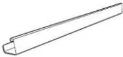 | Top Mounting Rail(With foam) | 1 |
 | Lock Frame | 2 |
 | Accordion Panels(With "left" & 'Right" marked on the front face) | 2 |
 | Sash Lock(Two holes) | 1 |
 | Window Sash Seal(Foam) | 1 |
 | 3/8" Screws | 4 |
 | 1/2" Screws | 3 |
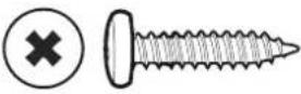 | 3/4" Screws | 4 |
 | Insulation for the Accordion Panels(Thin sponge for back-up using) | 1 |
 | Insulation Strip(Foam) (Only for E-Star models) | 2 |


NOTE: Save carton and these Installation Instructions for future reference. The carton is the best way to store unit during winter or when not in use.
INSTALLATION & ASSEMBLY INSTRUCTIONS (CONT.)
Some assembly is required for your new air conditioner. Please read and follow these instructions carefully.
- This air conditioner is designed to be installed in a standard double-hung window with a window width between 23" and 36" (584 mm - 914 mm).
- The air conditioner can be installed without the accordion panels to fit in a narrow window opening. See the window dimensions.
- The Lower Sash (the lower part of the window that moves up and down) must allow for 1412 " of vertical clearance when open. (See FIG. 1).
- All supporting parts must be secured to firm wood, masonry, or metal.
- The electrical outlet must be within reach of the power cord.

NOTE: Save the product packaging and installation instructions for future reference. Store the air conditioner in the product box when not in use for an extended period of time.
Top Rail Assembly
The top rail must be assembled prior to installing the air conditioner in the window Tools Needed: Phillips Head Screw Driver
| Top Rail Hardware | QTY | |
| 3/8”Screw | 4 | |
| TopRail | 1 | |
Attaching the Top Rail to the Air Conditioner
- Remove the air conditioner from the box and place on a hard and flat surface.
- Remove top rail from the top of the packaging material as shown in FIG. A.
- Align the hole in the top rail with those in the top of the unit as shown in FIG. B.
- Secure the top rail to the unit with the 3/8" screws as shown in FIG. C.
CAUTION
When handling the unit, be careful to avoid cuts from the sharp metal edges and aluminum fins on the front and rear coils.
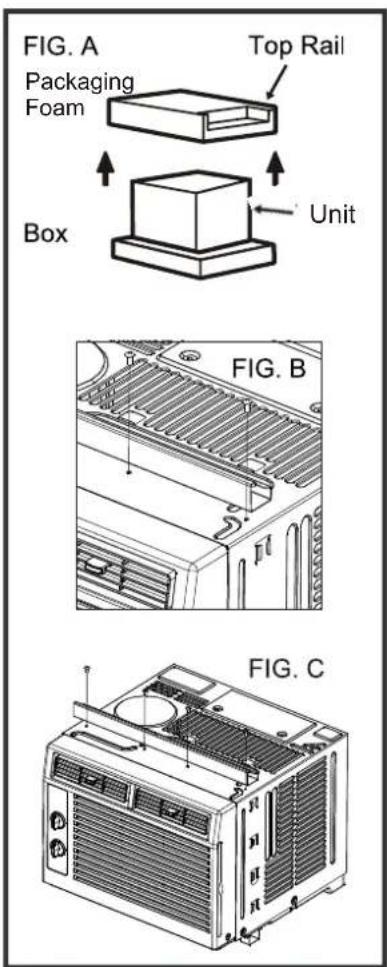
NOTE: For safety reasons, all 4 screws must be used to attach the top rail.
INSTALLATION & ASSEMBLY INSTRUCTIONS (CONT.)
Accordion Panel Installation
Now that you have installed the top rail, you can now install the accordion panels on each side.
- Place the air conditioner on a hard flat surface.
- Locate the accordion panels in the box.
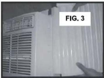
- Gently pull the free end of the accordion panel (See FIG. 2). Do this for both panels.

natural_image
Close-up of hands holding a bundle of transparent plastic strips (no text or symbols visible)- Slide the free end of the accordion panel into the side panel of the air conditioner (See FIG. 3). Do this for each side.
natural_image
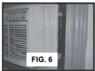
Exterior view of a white industrial ventilation unit with ventilation grilles and a hand pointing to the side (no visible text or symbols)- Once the accordion panels are slid into place adjust the top and bottom rails of the accordion panels into the top and bottom rails of the air conditioner (See FIG. 4).

natural_image
Exterior view of a white air conditioner unit with ventilation grilles and ventilation grilles (no visible text or symbols)Storm Window Requirements
A storm window frame will not allow the air conditioner to tilt properly which in turn will keep it from draining properly. To adjust for this, attach a board or piece of wood to the sill. The board or wood piece should have a depth of at least 1 1/2". Make sure the board or piece of wood is approximately 1/2" higher than the storm window frame. This will allow the air conditioner to tilt enough for proper drainage. (See FIG. 5).

Placing the Unit Inside a Window
- Place the air conditioner on the sill with the bottom mounting rail against its back edge. Center the air conditioner and close the window securely behind the top mounting rail. The air conditioner should be slightly tilted to the outside area. NOTE: Check that air conditioner is tilted back approximately 34 " to 1". (Tilted about 3^ to 4^ downward to the outside). If, after proper installation, condensation does not drain from the overflow drain hole during normal use, adjust slope. (See FIG. 6 & FIG. 7) (Suggested to keep a downward slope to let accumulated rain water to drain out from the backside of the unit's bottom.)
natural_image
Exterior view of a white air conditioner unit with ventilation grilles and a label 'FIG. 6' (no other text or symbols visible)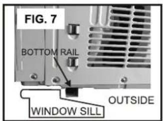
- Once the air conditioner is installed, extend both the left and the right accordion panels to the width of the window.

natural_image
Hand placing a fan into a white air vent (no text or symbols visible)INSTALLATION & ASSEMBLY INSTRUCTIONS (CONT.)
Frame Lock, Sash Lock, and Foam Seal Installation
| MOUNTING HARDWARE | |||
| Qty | |||
| [0255] |  | 3/4" Screws | 4 |
 |  | 1/2" Screws | 3 |
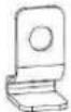 | Frame Lock | 2 | |
 | Sash Lock | 1 | |
Tools Needed:
Phillips Head Screw Driver Drill (if plot holes are needed)
- Place the frame lock between the extended accordion panels and the window sill as shown in FIG. 9. Screw a 3/4" (19 mm) locking screw through the frame lock and into the window sill. (FIG. 10)

natural_image
Close-up of a window with horizontal slats and a small object on the right side (no text or symbols visible)
natural_image
Close-up of a hand holding a tool near a white panel, labeled 'FIG. 10' (no other text or symbols visible)- Drive 1/2" screws into the top of the accordion panel frame and the top rail to securely attach the window air conditioner to the lower sash. (See FIG. 11/12)
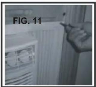
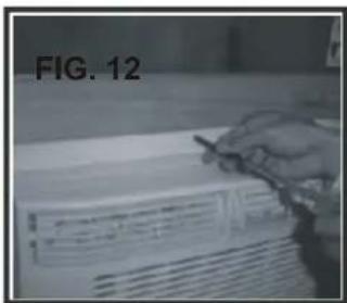
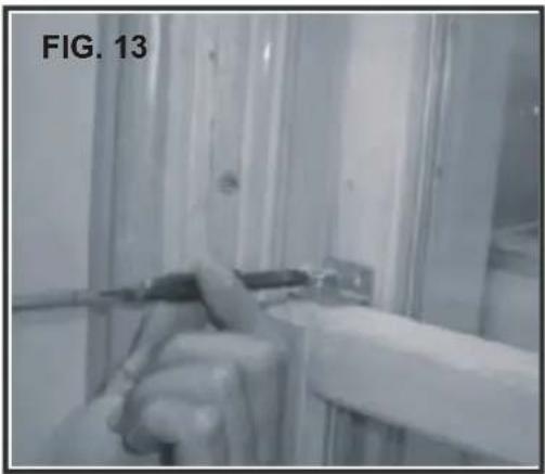
- To secure the lower sash into place, use the sash lock and a 3/4" screw as shown below. (See FIG. 13)
natural_image
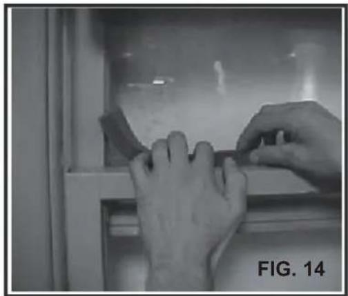
Interior view of a room with glass partitions and a hand holding a tool (no visible text or symbols)- For added insulation, cut the supplied insulation foam to the width of the window. Insert the foam between the window sashes to prevent outside air and object from getting into the room. (See FIG. 14)
natural_image
Close-up of hands installing or adjusting a component on a window (no visible text or symbols)Removing the Air Conditioner from the Window
- Turn the air conditioner off and disconnect the power cord.
- Remove the sash seal from between windows and unscrew sash lock.
- Remove the screws installed through the frame and frame lock.
- Slide the side panels out of the frame.
- Keeping a firm grip on the air conditioner, raise the sash and carefully tilt the air conditioner backwards to drain any condensate water in the base of the unit. Be careful not to spill any remaining water while lifting the unit from window.
- Store parts WITH the air conditioner in the original box or in an area with low humidity.
INSTALLATION & ASSEMBLY INSTRUCTIONS Introduction to Refrigerants R32
- Before installing the appliance, you must read the manual carefully to get the safety information and notes.
- When filling the combustible refrigerant, any of your rude operations may cause serious injury or injuries to human body or bodies and object or objects.
● A leak test must be done after the installation is completed. - It is a must to do the safety inspection before maintaining or repairing an air conditioner using combustible refrigerant in order to ensure that the fire risk is reduced to minimum.
- It is necessary to operate the machine under a controlled procedure in order to ensure that any risk arising from the combustible gas or vapor during the operation is reduced to minimum.
- Requirements for the total weight of filled refrigerant and the area of a room to be equipped with an air conditioner (are shown as in the following Tables GG.1 and GG.2)

The maximum charge and the required minimum floor area
$$ m _ {1} = \left(4 m ^ {3}\right) \times L F L, m _ {2} = \left(2 6 m ^ {3}\right)) \times L F L, m _ {3} = \left(1 3 0 m ^ {3}\right) \times L F L $$
Where LFL^3 ^3
is the lower flammable limit
For the appliances with a charge amount m_1 < M ≤slant m_2 :
The maximum charge in a room shall be in accordance with the following: m_ = 2.5 × (L^1/2 L)^(5/4) × h_0 × (A)
The required minimum floor area Amin to install an appliance with refrigerant charge M (kg)
shall be in accordance with following: A_ = (M / (2.5 × (LFL)^(5/4) × h_0))^2
Where:
m_max is the allowable maximum charge in a room, in kg;
M is the refrigerant charge amount in appliance, in kg;
Amin is the required minimum room area, in m2;
A is the room area, in m ^2 ;
LFL is the lower flammable limit, in kg/m ^3 ;
h_0 is the installation height of the appliance, in meters for calculating m_max or A_min , 1.8 m for wall mounted;
Table GG.1 Maximum charge (kg)
| Category | LFL(kg/m3) | h_0 (m) | Floor area(m2) | ||||||
| 4 | 7 | 10 | 15 | 20 | 30 | 50 | |||
| R32 | 0.306 | 0.6 | 0.68 | 0.9 | 1.08 | 1.32 | 1.53 | 1.87 | 2.41 |
| 1 | 1.14 | 1.51 | 1.8 | 2.2 | 2.54 | 3.12 | 4.02 | ||
| 1.8 | 2.05 | 2.71 | 3.24 | 3.97 | 4.58 | 5.61 | 7.254 | ||
| 2.2 | 2.5 | 3.31 | 3.96 | 4.85 | 5.6 | 6.86 | 8.85 | ||
Table GG.2 Minimum room area ( m^2 )
| Category | LFL (kg/m^3) | h_0 (m) | Charge amount ( M ) (kg)Minimum room area( m^2 ) | ||||||
| R32 | 0.306 | 1.224 kg | 1.836 kg | 2.448 kg | 3.672 kg | 4.896 kg | 6.12 kg | 7.956 kg | |
| 0.6 | 29 | 51 | 116 | 206 | 321 | 543 | |||
| 1 | 10 | 19 | 42 | 74 | 116 | 196 | |||
| 1.8 | 3 | 6 | 13 | 23 | 36 | 60 | |||
| 2.2 | 2 | 4 | 9 | 15 | 24 | 40 | |||
INSTALLATION & ASSEMBLY INSTRUCTIONS
Introduction to Refrigerants R32
1. Site Safety


Open Flames Prohibited Ventilation Necessary
2. Operation Safety
Mind Static Electricity
Open Flames Prohibited

Must Wear Protective Clothing and anti-static gloves


Don't use mobile phone
3. Installation Safety
●Refrigerant Leak Detector
●Appropriate Installation Location

The left picture is the schematic diagram of a refrigerant leak detector.
Please note that:
- The installation site should be in a well-ventilated location.
- The sites for installing and maintaining an air conditioner using Refrigerant R32 should be free from open fire or welding, smoking, drying oven or any other heat source higher than 548°C which easily produces open fire.
- When installing an air conditioner, it is necessary to take appropriate anti-static measures such as wearing anti-static clothing and/or gloves.
- It is necessary to choose a site convenient for installation or maintenance wherein the air inlets and outlets of the indoor and outdoor units should be not surrounded by obstacles or close to any heat source or combustible and/or explosive environment.
- If the indoor unit incurs a refrigerant leak during the installation, all the personnel should go out till the refrigerant leaks completely for 15 minutes. If the product is damaged, you must return the damaged product back to the manufacturer; it is prohibited to weld the refrigerant pipe or conduct other changes to the product.
-
It is necessary to choose a place where the inlets and outlets air of the indoor unit is even.
-
It is necessary to avoid using in places where there are other electrical products, power switch plugs and sockets, kitchen cabinets, beds, sofas and other valuables that are placed right under the indoor unit, as this prevents mechanical damage from occurring.
USING YOUR AIR CONDITIONER
Manual Control Panel

Normal Operating Sounds
- You may hear a pinging noise caused by water hitting the condenser on rainy days, or when the humidity is high. The design features help remove moisture and improve efficiency.
- You may hear the thermostat click when the compressor cycles on and off.
- Water will collect in the base pan during rain or days of high humidity. The water may overflow and drip from the outside part of the unit.
-
The fan may run even when the compressor is not on.
-
Digital Display: Shows the set temperature. Operation modes are: Cool, Dry, Fan, and Auto. Time is displayed using the timer setting.
- Mode Button: Press the mode button to cycle through the various modes: Cool, Dry, Fan and Auto.
Cool Mode: The cooling function allows the air conditioner to cool the room and at the same time reduces humidity. Press the MODE button to activate the cooling function. To optimize this function, adjust the temperature by pressing the up and down arrows and the speed by pressing the Fan Speed button.
Dry Mode: This function reduces the humidity of the air to make the room more comfortable. Press MODE button to set the DRY mode.
Fan Mode: This mode will only circulate the air. Press MODE button to select FAN MODE. Pressing the FAN SPEED button allows you to change the fan speed setting from HI, MED and LO. If using the remote control, it will store the fan speed setting from the most previous use.
Auto Mode: In AUTO mode the unit automatically chooses the fan speed and the mode of operation (COOL, DRY or FAN). In this mode the fan speed and temperature are set automatically according to the room temperature (Room temperature is determined by the temperature sensor located in the unit.)
-
△ and √ Button: Use these buttons on the control panel and remote to increase or decrease the Set Temperature or Timer. Temperature range is between 61°F and 88°F (16°C-31°C).
-
Sleep Button: Press the SLEEP button, all of the display lights will turn off after a while, but the sleep light is always on. In the mode, the air conditioner will automatically adjust the temperature and fan speed to make the room more comfortable during the night. The set temperature will automatically change every 30-60 minutes and at most change six times until the set temperature is 81 or 82° F
-
Eco Button: When the unit is in ECO mode, the light will turn on. In ECO mode, the unit will turn off once the room is cooled to the user-set temperature.
The unit will turn back on when the room temperature rises above the user-set temperature. Before the compressor starts, the fan motor will run for a while, then it will stop for a while, and will repeat to provide a much more comfortable feeling and save energy.
-
Power Button: Turn the air conditioner on and off.
-
Filter Button: When the Filter Check light is off, it is not necessary to press the Filter Check button. When the Filter Check light is on, you can turn off the light by pressing the Filter Check button. After the fan motor works for 500 total hours, the Filter Check light will turn on to remind the user to clean the filter.
-
Timer Button: Use these buttons on the control panel and remote to set the Timer.
Timer Off: The timed stop is programmed by pressing TIMER button. Set the rest time by pressing the button “^” or “∨” until the rest time displayed is to your demand then press TIMER button again.
Timer On: When the unit is off, press TIMER button at the first time, set the temperature with pressing the button “^” or “∨”. Press TIMER button at the second time, set the rest time with pressing the button “^” or “∨”. Press TIMER button at the third time, confirm the setting, then it will show on the display.
Note: It can be set to automatically turn off or on in 0.5-24 hours. Each press of the “^” “∨” buttons will increase or decrease the timer. The Timer can be set in 0.5 hours increment below 10 hours and 1 hour increment for 10 hours or above. The SET light will turn on while setting. To cancel the set function, press the TIMER button again.
- Fan Speed Button: Press the FAN SPEED button to select the fan speed. In COOL MODE you can choose the following settings: HI, MED, LO, or AUTO. In Fan MODE you can choose from HI, MED, and LO.
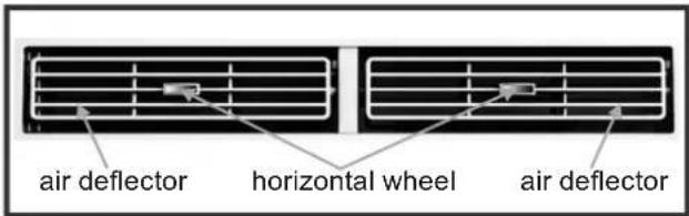
- Directional Louvers: Use the horizontal wheels to control horizontal airflow and the air deflectors to control vertical airflow.
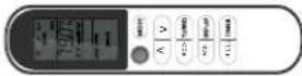
REMOTE CONTROL
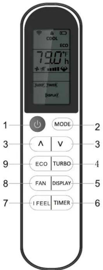
- POWER: Turn the air conditioner on and off.
- MODE: Press the button to select the mode of operation, AUTO, COOL, DRY, FAN and HEAT Note: The HEAT mode is inactive for COOL ONLY models. Press and hold the MODE button for more than 5 seconds to delete or add the HEAT mode on remote.
- "A" and "V": Use these buttons to increase or decrease the Set Temperature or Timer Temperature range is 61°F to 88°F (16°C-31°C)
-
TURBO: When the remote is ON, press the TURBO button to activate high fan mode. NOTE For °F to°C change: After inserting the batteries in the off state, within 3 minutes, press and hold TURBO button for 5+ seconds to switch display from °F to °C.
-
DISPLAY: By pressing the DISPLAY button, this will switch off/on all lights or LED display.
- TIMER: Use the buttons on the control panel and remote to set the TIMER
Timer Off: When the unit is on, timer can be set by pressing the TIMER button. Set the run time by pressing the up "^\" or down "^\" button until the desired run time is displayed, then press TIMER button again.
Timer On: When the unit is off, set the temperature by pressing the "∧" or "∨" button. Then press the TIMER button to set the timer by pressing the "∧" or "∨" button. Then Press TIMER button again to confirm. Both the TIMER and indicators will illuminate once set.
NOTE: It can be set to automatically turn off or on in 30 minutes to 24 hour intervals. Each press of the "^" or "∨" buttons will increase or decrease the timer. The TIMER can be set in 30 minute increments up to 10 hours, and 1 hour increments for 10 or hours and above. The SET light will turn on while setting. To cancel the set function, press the TIMER button again.
-
"I FEEL": Press the "I FEEL" button to activate the follow me function, which enables the remote to take the temperature at its current location, and send this signal to the air conditioner to optimize the temperature around you and ensure comfort.
-
FAN: Press the "FAN" speed button to select the fan options. You can choose HI, MED, LO or AUTO in COOL MODE or HEAT MODE, and HI, MED, LO in FAN MODE.
-
ECO: When the unit is in ECO mode, the light will illuminate. In ECO mode, the unit will turn off once the room is cooled to the set temperature. The unit will turn back on when the room temperature rises above the set temperature. Before the compressor starts, the fan motor will keep cycling, to provide for a comfortable environment, while saving energy.
Battery Size: AAA - NOTE: Do not mix old and new batteries or different types of AAA batteries.
CARE AND MAINTENANCE
Clean your air conditioner to keep it looking new, minimize dust build up and for optimal performance.
Air Filter Cleaning
The air filter should be checked at least once a month to see if it needs cleaning. Trapped particles and dust can build up in the filter and may decrease airflow as well as cause the cooling coils to accumulate frost.
To clean the air filter, power the unit off and:
- Remove the filter by pulling down on the indents of the filter door on the front of the unit. (See FIG.15)
- Wash the filter using liquid dish soap or mild detergent and warm water. Rinse the filter thoroughly. Gently shake the filter to remove excess water.
- Let the filter dry completely before placing it into the air conditioner.

NOTE:
If you do not wish to wash the filter, you may vacuum the filter to remove the dust and other particles.
Wear and Tear
To minimize wear and tear on the air conditioner, always wait at least 3 minutes before changing modes. This will help prevent the compressor from overheating and the circuit breaker from tripping.
Cabinet Cleaning
To clean the air conditioner cabinet:
- Power off and unplug the air conditioner to prevent shock or fire hazard. The cabinet and front panel of the air conditioner may be dusted with an oil-free cloth or wiped down with a damp cloth in a solution of warm water and mild liquid soap. Rinse thoroughly with a damp cloth and wipe dry.
- Never use harsh cleaner, wax or polish on the front of the cabinet.
- Be sure to wring excess water from the cloth before wiping around the controls. Excess water in or around the controls may cause damage to the air conditioner.
Winter Storage
To store the air conditioner when it is not in use for an extended period of time, remove it carefully from the window according to the installation instructions and cover it with plastic or place it in the original box. Remove the batteries from the remote before storing.
TROUBLESHOOTING
| PROBLEM | POSSIBLE CAUSES | SOLUTIONS |
| The Air Conditioner will not start. | The air conditioner is unplugged. | Make sure the air conditioner plug is pushed completely into the outlet. |
| The fuse is blown/circuit breaker is tripped. | Check that there is no damage to the plug fuse / circuit breaker box and replace the fuse or reset the breaker. | |
| Power failure. | The unit will automatically re-start when power is restored.There is a protective time delay (approx. 3 minutes) to prevent tripping of the compressor overload. For this reason, the unit may not start normal cooling for 3 minutes after it is turned back on. | |
| The current interrupter device is tripped. | Press the RESET button located on the power cord plug.If the RESET button will not stay engaged, discontinue use of the air conditioner and contact a qualified service technician. | |
| The Air Conditioner does not cool as it should. | Airflow is restricted. | Make sure there are no curtains, blinds, or furniture blocking the front of the air conditioner. |
| The temperature setting may not be set correctly. | Lower the set thermostat temperature. | |
| The air filter is dirty. | Clean the filter. See the Cleaning and Care Section of the manual. | |
| The room may be too warm. | Please allow time for the room to cool down after turning on the air conditioner. | |
| Cold air is escaping. | Check for open furnace registers and cold air returns. | |
| The cooling coils are frozen. | See "The Air Conditioner is Freezing Up" below. | |
| The Air Conditioner is freezing up. | Ice blocks the air flow and stops the air conditioner from cooling the room. | Set the MODE dial to HIGH FAN or HIGH COOL and set the thermostat to a higher temperature. |
| The Remote Control is not working. | The batteries are inserted incorrectly.The batteries may be dead. | Check the position of the batteries.Replace the batteries. |
| Water is dripping outside. | Hot and humid weather. | This is normal. |
| Water is dripping inside the room. | The air conditioner is not correctly pitched towards the outside. | For proper water drainage, make sure the air conditioner is slightly pitched downwards from the front of the unit to the rear (Refer to installation instructions). |
| Water collects in the base pan. | Moisture removed from the air is draining into the base pan. | This is normal for a short period in areas with low humidity and normal for a longer period in areas with high humidity. |
NOTE
A highly recommended troubleshoot for any issue in general consists of turning off unit and unplugging for 5 minutes. It is also recommended to try another wall outlet. For further assistance, contact Consumer Services at 855-663-9463.

ARCTIC WIND®
5401 Dansher Road
Countryside, IL 60525
855-663-9463 | support@arcticwindac.com | www.arcticwindac.com
- CONONSSUUMMEERR P PRRODODUCUCTT I
- TABLE OF CONTENTS
- INTRODUCTION TO REFRIGERANTS R32
- Warnings
- IMPORTANT SAFETY INSTRUCTIONS (CONT.)
- ! DANGER
- WARNING
- FCC Caution.
- ELECTRICAL REQUIREMENTS
- Electrical Shock Hazard
- Wiring Requirements
- Power Supply Cord
- Recommended Ground Method
- It is the customer's responsibility:
- Copies of the standards listed may be obtained from:
- LCDI Power Cord and Plug
- INSTALLATION HARDWARE INCLUDED
- INSTALLATION & ASSEMBLY INSTRUCTIONS (CONT.)
- Top Rail Assembly
- Attaching the Top Rail to the Air Conditioner
- CAUTION
- Accordion Panel Installation
- Storm Window Requirements
- Placing the Unit Inside a Window
- Frame Lock, Sash Lock, and Foam Seal Installation
- Tools Needed:
- Removing the Air Conditioner from the Window
- INSTALLATION & ASSEMBLY INSTRUCTIONS Introduction to Refrigerants R32
- The maximum charge and the required minimum floor area
- INSTALLATION & ASSEMBLY INSTRUCTIONS
- Site Safety
- Operation Safety
- Installation Safety
- Please note that:
- Normal Operating Sounds
- REMOTE CONTROL
- CARE AND MAINTENANCE
- Air Filter Cleaning
- NOTE:
- Wear and Tear
- Cabinet Cleaning
- Winter Storage
- NOTE
- ARCTIC WIND®
Brand : ARCTIC WIND
Model : 2AW6000DA
Category : Air Conditioning