BMR60DODFW - Oven BELLING - Free user manual and instructions
Find the device manual for free BMR60DODFW BELLING in PDF.

| Product Type | Built-in Electric Oven |
| Brand | Belling |
| Model | BMR60DODFW |
| Oven Type | Multifunction |
| Energy Source | Electric |
| Energy Rating | A+ |
| Total Oven Capacity | 65 Liters |
| Dimensions (H x W x D) | 595 x 595 x 575 mm |
| Cutout Dimensions (H x W x D) | 590 x 560 x 550 mm |
| Weight | 34 kg |
| Power Supply | 220-240 V, 50 Hz |
| Maximum Power Consumption | 3.2 kW |
| Oven Functions | Conventional, Fan-forced, Grill, Base heat, Fan + Grill, Defrost |
| Temperature Range | 50°C - 275°C |
| Cleaning Type | Catalytic (back panel) |
| Interior Light | Yes, with replaceable bulb |
| Control Type | Knobs and digital timer |
| Safety Features | Child lock, automatic shut-off, cool-touch door |
| Spare Parts Availability | Replaceable heating elements, thermostat, door seal, glass |
| Repairability Index | 8.5 / 10 |
| User Manual Included | Yes, in English (PDF download available) |
Frequently Asked Questions - BMR60DODFW BELLING
User questions about BMR60DODFW BELLING
0 question about this device. Answer the ones you know or ask your own.
Ask a new question about this device
Download the instructions for your Oven in PDF format for free! Find your manual BMR60DODFW - BELLING and take your electronic device back in hand. On this page are published all the documents necessary for the use of your device. BMR60DODFW by BELLING.
USER MANUAL BMR60DODFW BELLING
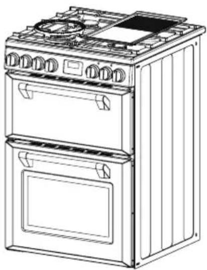
BMR60DODFB BMR60DODFW
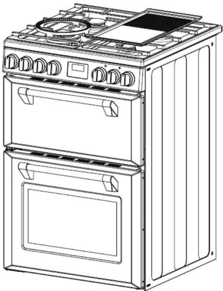
Freestanding Double Oven with Gas Cooktop
natural_image
Line drawing of a two-tier electric stove with open doors and top cabin (no text or symbols)INSTRUCTION MANUAL
belling.com.au | belling.co.nz
Dear Customer,
Congratulations on the purchase of your new product from Belling.
We recommend you please take some time to read the instruction manual thoroughly to familiarise yourself with the functionality and operations to ensure optimum performance of your new appliance.
After reading the manual, please store it in a safe and accessible location for future reference.
Installation
The installation of your new appliance must be carried out by a qualified installer / technician in accordance to local regulations. Please ensure all packaging materials are disposed of correctly.
Customer Care
Our Customer Care centre is available should you wish to learn more about your appliance in relation to how to use it to its best potential, or tips on cleaning as well as available accessories.
For further details please contact our Customer Care Team
Australia
Ph: 1300 556 816
customer.care.ha@glendimplex.com.au
New Zealand
Ph: 09 274 8265
nztechserv@glendimplex.co.nz
Thank you.
Regards,
Belling Australia and New Zealand
| PRODUCT / INSTALLER DETAILS 4 | |
| WARNINGS & PRECAUTIONS 5 - 8 | |
| Safety precautions 5 | |
| Other Important Safety Information 6 | |
| Warning for Use of Grill,Oven & Appliance Hob | 6 |
| Installation Warnings 7 | |
| Cleaning & Service Warnings 8 | |
| Electrical Shock Hazard 8 | |
| Disposal of your old Machine 8 | |
| OPERATION | 9 - 19 |
| Product Overview 9 | |
| Control Panel 10 | |
| Preparing your Product for the First Time | 11 |
| Using the Oven of your Electric Cooker | 12 |
| Oven Temperature (Thermostat) Knob | 14 |
| Using the Top Oven / Grill of your Electric Cooker | 14 |
| Start Cooking Now & Set Cooking Time | 16 |
| Start Cooking Now & Set the Finish Time | 17 |
| Cooking Guide 18 | |
| Using the Hotplates of your Cooker 19 |
| FITTING ACCESSORIES & CLEANING | 20 - 25 |
| Safety Warnings Regarding Cleaning | 20 |
| Cleaning the Gas Hob | 21 |
| Cleaning the Oven | 23 |
| Replacing the Oven Lamp | 25 |
| HINTS & TIPS | 26 - 27 |
| INSTALLATION | 28 - 36 |
| Installing your new Cooker | 28 |
| Unpacking Instructions for Installer | 28 |
| Locating the Cooker | 28 |
| Fitting a Power Supply Cable | 31 |
| Connection to the Gas Supply | 32 |
| Testing the Cooker Features | 36 |
| TECHNICAL SPECS | 37 - 38 |
| MANUFACTURER GUARANTEE | 39 - 41 |
| Icon Type | Meaning | |
| Warning Serious injury or death risk | ||
| Risk of electric shock | Dangerous voltage risk | |
| Symbol ISO 7010 W021 Warning; Risk of fire / flammable materials | ||
| Caution | Injury or property damage risk | |
| Important / Note | Operating the system correctly | |
PRODUCT / INSTALLER DETAILS
For future reference we suggest that you staple a copy of your purchase receipt here and complete the below so the information is always at hand.
PRODUCT DETAILS
Model number: ____
Serial number: ____
(Located on the product rating label)
Description:
PURCHASE DETAILS
Date of purchase: ____
Place of purchase: ____
Store name: ____
Address: ____
Telephone: Invoice / receipt number: ____
INSTALLATION DETAILS
Electrical Details
Date of installation: ____
Company / installers name: ____
Licence number: ____
Telephone number: ____
Gas Details
Date of installation: ____
Company / installers name: ____
Licence number: ____
Telephone number: ____
Plumbing Details
Date of installation: ____
Company / installers name: ____
Licence number: ____
Telephone number: ____
Carefully read all instructions before using your appliance and keep them in a convenient place for reference when necessary.
CONDITIONS OF USE: This appliance is intended to be used for domestic use, not commercial use.
SAFETY PRECAUTIONS
This appliance is not intended for use by persons (including children) with reduced physical, sensory or mental capabilities, or lack of experience and knowledge, unless they have been given supervision or instruction concerning use of the appliance by a person responsible for their safety.
WARNING: ensure that no downward pressure is applied to the oven door when open. In particular, do not allow a child to climb on to open oven door.
WARNING: accessible parts can become hot during use, especially the oven door. To avoid burns, young children must be kept away.
WARNING: Young children should be supervised to ensure they do not play with this appliance.
WARNING: During use this appliance becomes hot. Care should be taken to avoid touching hot external and internal surfaces when in use. Use oven gloves.
CAUTION: The cooking process has to be supervised. A short term cooking process has to be supervised continuously.
After using the appliance, make sure that all controls are in 'CLOSED' or 'OFF' position.
Install cooker, shelving and fittings in accordance with this Manual.
The appliance is NOT suitable for installation or use with aftermarket lids or covers.
Ensure all specified vents, openings and airspaces are not blocked. Make sure that air is able to circulate freely around the appliance. Poor ventilation produces a shortage of oxygen.
To ensure your safety all electric appliances should only be installed or serviced by qualified staff. If the supply cord is damaged, it must be replaced by a service agent or similarly qualified person in order to avoid a hazard.
WARNING: DO NOT spray aerosols in the vicinity of this appliance while it is in operation.
WARNING: DO NOT store flammable materials in the appliance or near the appliance.
WARNING: DO NOT store items of interest to children in cabinets above the appliance. Children climbing on the cooktop could be seriously injured.
DO NOT modify this appliance.
CUT HAZARD: Take care, panel edges are sharp! Failure to use caution could result in injury or cuts.
The appliance is NOT intended to be operated by means of an external timer or separate remote-control system.
Appliance must be installed according to current laws and regulations by qualified tradesmen / installers.
This appliance is intended to be used in a domestic household environment ONLY!
Commercial use of any kind is NOT covered under the manufacturer's warranty!
OTHER IMPORTANT SAFETY INFORMATION
This appliance MUST NOT be used as a space heater.
DO NOT obstruct the ventilation slots on front or back of appliance.
DO NOT remove any labels or use abrasive / corrosive cleans on them.
Accoring to the electrical safety regulations the appliance equipment MUST BE properly earthed.
WARNING FOR USE OF GRILL, OVEN, AND APPLIANCE HOB
Oven Warnings
DO NOT push down or apply any weight on open oven door.
DO NOT place dishes on open door of oven.
DO NOT line oven with foil or place anything on the bottom of the oven while baking to avoid permanent damage, as trapped heat will crack or craze the enamel floor of the oven cavity liner.
Use of olive oil and other poly-unsaturated oils (vegetable oils) when roasting uncovered food causes deposits inside the oven which are very difficult to remove.
Care should be taken to avoid touching heating elements.
Always use oven gloves to place cookware in the oven or when removing it.
Always grip the oven door handle in the centre.
Hotplate warnings
DO NOT allow pots to boil dry, as damage to hotplate may result.
DO NOT operate burners without a pot, fry pan etc.
DO NOT allow cookware to overhang hob onto adjacent bench tops, this will cause scorching to the bench top surface.

WARNING: NO combustible material or products should be placed on this appliance at any time.
DO NOT place or drop heavy objects on your cooktop.
Handles of saucepans may be hot to touch.
Check saucepan handles do not overhang other cooking zones that are on.
Keep handles out of reach of children.

WARNING: Unattended cooking on a hob with fat or oil can be dangerous and may result in fire. NEVER try to extinguish a fire with water, but switch off the appliance and then cover flame e.g. with a lid or a fire blanket.
Children shall be kept away unless continuously supervised.

WARNING: Failure to follow this advice could result in burns and scalds.
After use, always turn off the cooking zones and the cooktop as described in this manual (i.e. by using the control knobs / touch controls).
Ensure burner caps and crowns are in their correct position to avoid damage to these parts.
Use of a gas cooking appliance produces heat and moisture in the room in which it is installed. Ensure that the room is well ventilated by keeping the air intakes open and in good working order or by installing an extractor hood with discharge pipe.
INSTALLATION WARNINGS

CAUTION: If this cooking range is to be connected to a new or upgraded electrical installation, then it MUST be connected to the supply by a supply cord fitted with;
an appropriately rated plug that is compatible with the socket-outlet fitted to the final sub-circuit in the fixed wiring that supplies this cooking range; or an appropriately rated insulated male connector that is compatible with the insulated female connector fitted to the final sub-circuit in the fixed wiring that supplies this cooking range.
An authorized person MUST install this appliance. (Certificate of Compliance to be retained).
Before using the appliance, ensure that all packing materials are removed from the appliance.
In order to avoid any potential hazard, the Installation Instructions MUST be followed.

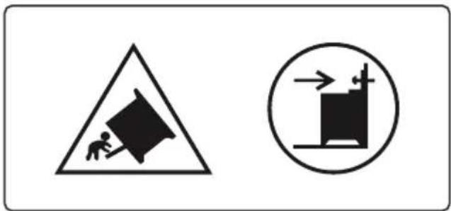
WARNING: In order to avoid accidental tipping of the appliance (for example, by a child climbing onto the open oven door), the anti tilt plate MUST be installed.
text_image
Warning sign with triangle and circle symbols indicating collision or hazard, including a person pulling a large block.The cooker MUST NOT be placed on a base or a plinth.
Where the appliance is installed next to cabinets, the cabinet material MUST be capable of withstanding 85°C.
Means for disconnection MUST be incorporated in the fixed wiring in accordance with the wiring rules.
Appliances requiring connection to 220-240V and MUST be earthed.
The power cord MUST NOT be accessible after installation.
Ensure the supply cord is not trapped or damaged during installation.
Alterations to the domestic wiring system MUST ONLY be made by a qualified electrician.

WARNING: Failure to follow this advice may result in electrical shock or death.
Failure to install the appliance correctly could invalidate any warranty or liability claims.
Gas models are NOT APPROVED for installation in marine craft, caravans or mobile homes.
Make sure that the appliance is supplied with the type of gas indicated on the data label and the gas type label next to the gas connection point.
CLEANING & SERVICE WARNINGS
Always ensure the appliance is switched off before cleaning.
DO NOT use corrosive cleaners e.g. caustic soda-based cleaners.
DO NOT use a steam cleaner to clean the appliance.
Always clean the appliance immediately after any food spillage.
Cleaning and user maintenance SHALL NOT be made by children without supervision.
To be serviced only by an authorized person.

Disconnect the appliance from the mains electricity supply before carrying out any work or maintenance on it.
DO NOT REPAIR OR REPLACE ANY part of the appliance unless specifically recommended in the manual. All other servicing should be done by a qualified technician.
DO NOT use scourers or any other harsh abrasive cleaning agents to clean your oven door, as these can scratch the glass which may result in shattering of the glass.
ELECTRICAL SHOCK HAZARD

WARNING: Switch the appliance off at the wall before cleaning or maintenance.

WARNING: If the supply cord is damaged, it MUST be replaced by the manufacturer, its service agent or similarly qualified persons in order to avoid a hazard.

WARNING: Failure to follow this advice may result in electrical shock or death.
DISPOSAL OF YOUR OLD MACHINE
This symbol on the product or on its packaging indicates that this product should not be treated as household waste. Instead it should be handed over to the applicable collection point for the recycling of electrical and electronic equipment.
By ensuring this product is disposed of correctly, you will help prevent potential negative consequences for the environment and human health, which could otherwise be caused by inappropriate waste handling of this product.
For more detailed information about recycling of this product, please contact your local city office, your household waste disposal service or the retailer who you purchased this product from.
The Manufacturers and Importers / Distributors and Retailers shall not be liable to any legal liability, personal injury and property damage due to incorrect operation or incorrect Installation.
Product Overview
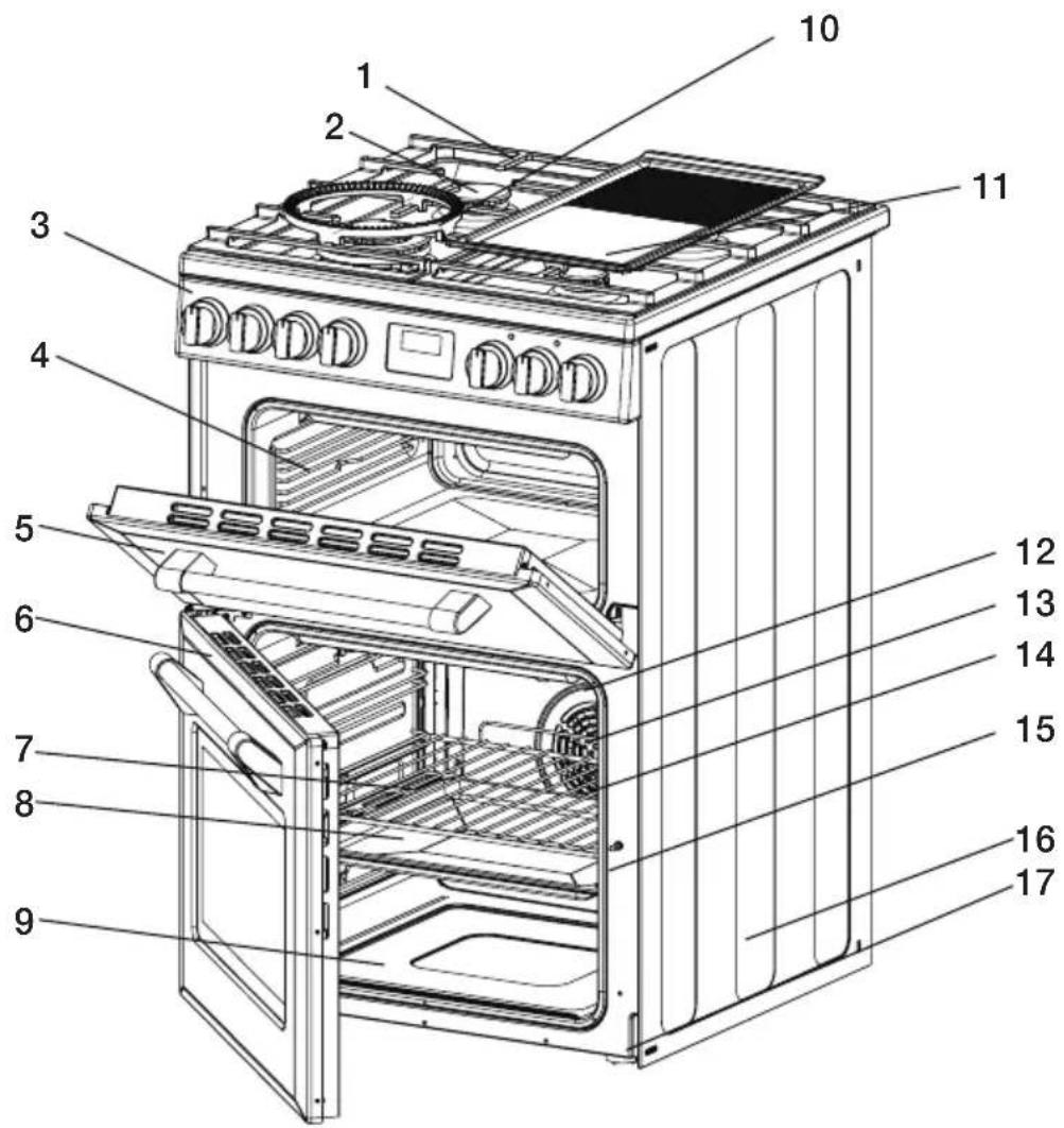
text_image
Exploded view diagram of a 17-inch oven with numbered parts for identification- Hotplate burners with removable caps x 4
- Cast Iron Trivets
- Control Panel
- Side Racks
- Top Oven Door
- Bottom Oven Door
- Shelf
- Baking Tray
-
Oven Element (Hidden under floor)
-
Wok adapter
- Griddle
- Oven Element (Hidden under floor) (conventional models only)
- Oven Element (fan forced models only)
- Fan & Element Cover (fan forced models only)
- Door Seal
- Side Panel
- Anti-Slip Feet
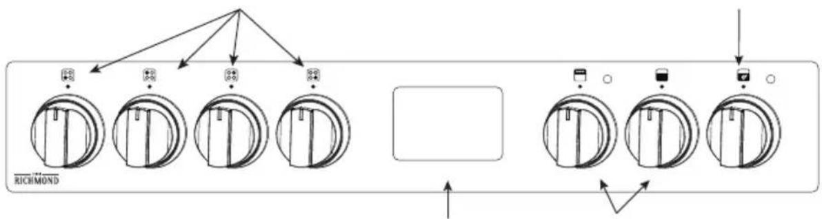
Control Panel
- Gas control knobs
flowchart
graph TD
    A[" "] --> B[" "]
    A --> C[" "]
    A --> D[" "]
    B --> E["RICHMOND"]
    C --> E
    D --> E
    E --> F[" "]
    F --> G[" "]
    G --> H[" "]
    H --> I[" "]
    I --> J[" "]
-
3 button programmable timer
-
Oven temperature control knob
flowchart
graph TD
    A["Control Switch 1"] --> B["Control Switch 2"]
    B --> C["Control Switch 3"]
-
Oven function control knobs
-
Gas control knobs: ignites gas and adjusts individual temperature
-
Oven temperature controls knobs: sets oven temperature
-
Oven function control knobs: sets the desired oven function
- 3 button programmable timer: sets the clock and timer
PREPARING YOUR PRODUCT FOR THE FIRST TIME
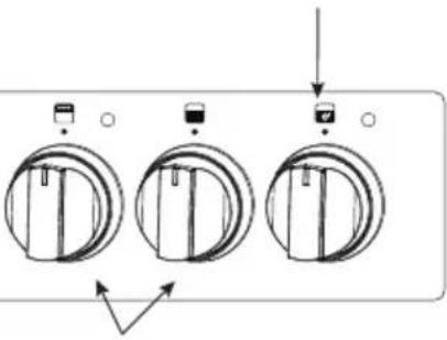
Oven shelf positions
The main oven has 5 shelf positions to choose from. Position 1 is the position at the bottom of the oven and position 5 is located at the highest point of the oven.
The 5 position side rack system can house both the standard oven shelves and baking tray.
text_image
Level 5 Level 4 Level 3 Level 2 Level 1Fitting oven shelves
Ensure shelf orientation is correct (refer picture).
The shelf has a safety bar fitted to reduce the risk of dishes sliding off the shelf, this is the rear of the shelf.
Slide into oven at an angle until raised back of shelf is past the stop on side runners.
Lower front of shelf and push in until stop is reached.

NOTE: The top ledge is not a shelf position.

natural_image
Technical illustration of an open refrigerator with internal structure and a magnified inset showing structural details (no text or symbols)Oven Safety Warnings
Always follow the instructions for putting the shelves and side racks into the oven, to avoid accidents.
Do not line the oven with foil, it will damage the enamel.
Do not place cookwares or anything else on the bottom of conventional oven model as trapped heat will damage the oven.
Do not touch the hot surfaces or heating elements inside the oven.
Do not use the oven door as a shelf.
Do not push down on the open oven door.
Do not place shelves on top of upper most shelf runner as there are no stops for shelf withdrawal.
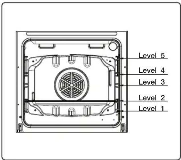
natural_image
Two identical diagrams of a door-like object with a small icon above, no text or symbols present.Control Knob 3: Temperature
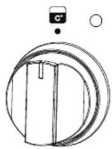
natural_image
Simple line drawing of a mechanical component with no text or symbolsControl Knob Icons (printed around the knobs)
Cooking Mode Selection Knob


Cooking Temperature Selection Knob

MAX
220
200
180
160
140
120
100
80

Cooktop Burner Control Knob


Oven Light
Turns on only the oven light, the light remains on for all other functions.

Defrost
The fan starts operating. To use this function, take your frozen food and place it in the oven on a shelf on the third slot from the bottom. It is recommended that you place an oven tray under the defrosting food to catch the melting ice. This function will not cook or bake your food, it will only help to defrost it.

Conventional Oven
When set to Conventional mode, the top and bottom heating elements operate together like a ‘normal’ conventional oven that you have probably used before. Conventional mode is best suited for traditional baking and roasting and you should only use one shelf at a time, otherwise the heat distribution will be uneven. You can balance the amount of heat between the top and the bottom of the dish by selecting a different shelf height. If you want more heat at the top of the dish place the dish on the top or second shelf. For more heat at the bottom of the dish, place the dish on third or fourth shelf.

Fan Forced
The ring heating element and fan will start operating. This function evenly disperses the heat in the oven. All foods on racks will be cooked evenly. It is recommended to pre-heat the oven for approximately 10 minutes.

Half Grill
The grill heating element will start operating. This function is ideal for grilling and toasting foods, use the upper shelves of the oven. Lightly brush the wire grid with oil to stop foods sticking and place foods in the centre of the grid. Always place a tray underneath to catch any drips of oil and fat. It is recommended to pre-heat the oven for approximately 10 minutes. When grilling, the oven door must be closed and the oven temperature should be set to 190-200°C.

Full Grill
The grill heating element and upper heating elements will start operating. This function is ideal for faster grilling and for covering a larger surface area, such as grilling meats. Use the upper shelves of the oven. Lightly brush the wire grid with oil to stop foods sticking. Always place a tray underneath to catch any drips of oil and fat. It is recommended to pre-heat the oven for approximately 10 minutes. When grilling, the oven door must be closed and the oven temperature should be set to 190-200°C.

Fan Grill
The grill heating element, upper heating elements and fan will start operating. This function is ideal for faster grilling of thicker foods and for covering a larger surface area. The fan will ensure even cooking. Use the upper shelves of the oven and place foods in the centre of the grid. Lightly brush the wire grid with oil to stop foods sticking. Always place a tray underneath to catch any drips of oil and fat. It is recommended to pre-heat the oven for approximately 10 minutes. When grilling, the oven door must be closed and the oven temperature should be set to 190-200°C.

Base Heat with Fan (Pizza)
The lower heating elements and fan will start operating. This function is ideal for baking food evenly, such as pastry or cakes. While the fan evenly disperses the heat of the oven, the lower heating element ensures the cooking and crisping of the base of the food.
OVEN TEMPERATURE (THERMOSTAT) KNOB
Selection of cooking temperature is carried out by turning the knob anti-clockwise to the required temperature, between 60°C to MAX.
If the appliance is electric the “oven indicator lamp” will come on when the oven is heating up.
When it goes out it means that it reaches the required temperature. The oven indicator lamp going 'on & off' during use is then normal. This means that oven temperature is being constantly maintained at the selected level.
Full Grill mode: Select 'Full Grill' mode with cooking mode selection knob and turn cooking temperature selection knob to 'Max'. When set to Grill mode, the top inner element operates. The extremely high and direct temperature of the grill makes it possible to brown the surface of meats and roasts while locking the juices in to keep them tender. Grill mode can also be used for dishes that require a high temperature on the surface such as beef steaks, veal, ribsteak, filets, hamburgers, etc. Grill food with the oven door closed (when not using fan).
Grill Safety Warnings
Always turn off the grill immediately after you have finished cooking and pull drawer out or remove grill tray otherwise fat left in the tray in the hot grill compartment will continue to smoke or could catch fire.
⚠ Wash grill tray & insert after every use.
Do not line the grill rack with foil.
Do not leave the grill unattended and check progress of cooking every 1 – 2 minutes (especially bread).
Do not try to grill place food more than 25mm thick. Food may catch fire.
Do not store flammable materials near the grill.

Conventional mode: When set to Conventional mode, the top and bottom heating elements operate together like a ‘normal’ conventional oven that you have probably used before. Conventional mode is best suited for traditional baking and roasting and you should only use one shelf at a time, otherwise the heat distribution will be uneven. You can balance the amount of heat between the top and the bottom of the dish by selecting a different shelf height. If you want more heat at the top of the dish place the dish on the top or second shelf. For more heat at the bottom of the dish, place the dish on third or fourth shelf.
Using the Programmable Clock (3 Button Digital Clock)
natural_image
Empty rectangular frame with black border (no text or symbols)


Function Description
| — | Decrease timer |
| Mode function | |
| + | Increase timer |
| Timer | |
| Cooking time | |
| Cooking end time | |
| Change time |
This model has a digital display, 24hr clock with 3 control buttons. When the power is connected, the screen displays '12:00' and the bar above the ' symbol flashes.
Setting the time when power is first connected
To set the correct time, press the “+” or “-” button to advance forward or backward until the correct time is displayed. After 5 seconds the time will be locked in.
Adjusting the time
Press the function button repeatedly until the bar above 'flashes, then press 'or 'button to set the time. After 5 seconds the time will be locked in.
Manual operation setting
When power is first connected, the oven will be in manual operation as soon as the time is set. Manual operation will only be cancelled if the power to the oven is switched off or if an automatic cooking time is selected and the bar above 'or' is hashing. See next section on 'Automatic setting'.
START COOKING NOW AND SET COOKING TIME
This semi-automatic setting of the oven allows you to start cooking immediately, set the cooking time (up to 10 hours), select the temperature and cooking mode.
The oven will cook according to the selected cooking mode and temperature and then switch off automatically once the cooking time has elapsed.
Automatic setting
Automatic setting of the oven allows you to select the end time, cooking time, temperature and cooking mode. The oven will switch on, cook according to the selected cooking mode and temperature and then switch off automatically.
- Press the function button repeatedly until the bar above flashes, then press '+or '-'button to set the time frame for cooking.
- Press the function button repeatedly until the bar above 'flashes, then press ' + or ' -button to set the time to switch off.
- Set cooking temperature and cooking mode by turning the thermostat knob and selector knob.
After these settings, the bars above 'and' with flash, indicating
that the automatic cooking feature of the oven is set.
FOR EXAMPLE: if cooking time takes 45 minutes and you want it to finish at 14:00
- Press the function button repeatedly until the bar above 'flashes and set the cooking time 45 minutes.
- Press the function button repeatedly until the bar above 'flashes and set the finish time to 14:00.
After the above setting, the current time is displayed and the bars above 'and' will flash indicating that the automatic cooking feature is set. When the clock displays '13:15', the oven will start cooking automatically. While cooking the bar will flash.
When the clock displays '14:00', the oven automatically stops cooking. The alarm will sound and the bar will flash, press any button to stop the alarm.
Semi automatic setting
There are two methods of semi-automatic cooking:
- Press the function button repeatedly until the bar above 'flashes, then press ' or ' — button to set the time frame for cooking.
- Set cooking temperature and cooking mode by turning the thermostat knob and selector knob.
The oven starts immediately, the bar above 'will flash. After the cooking time has elapsed, the oven automatically stops cooking. The alarm will ring and the bar above 'will flash, press any button to stop the alarm.
START COOKING NOW AND SET THE FINISH TIME
- Press the function button repeatedly until the bar above 'flashes, then press ' + or '-' button to set the time to finish cooking (up to 23 hours and 59 minutes).
- Set cooking temperature and cooking mode by turning the thermostat knob and selector knob.
The oven starts immediataely, the bar above 'will flash. When the finish time is reached, the oven automatically stops cooking. The alarm will ring and the above 'will flash, press any button to stop the alarm.
When any button is pressed during semi-automatic cooking, the set cooking time is displayed. If the finish time is set to the current time, the semi-automatic setting will be cancelled.
TIMER
The digital countdown timer can be set up to 23 hours and 59 minutes maximum.
To set the timer, press the function button repeatedly until the bar above ‘flashes. Then press ‘+or ‘-button to set the countdown timer. After 5 seconds, the time will be set and begin to count down. When the set time is reached, the bar above ‘disappears and the alarm will sound, press any button to stop the alarm.
After pressing the function button, timer settings should be done within 5 seconds.
In case of a power failure, all settings including the time display will be lost. The time and any settings will need to be re-set.
COOKING GUIDE
| Dishes | Fan-forced Conventional | |||||
| Thermostat (C) | Shelf position | Cook time (min) | Thermostat (C) | Shelf position | Cook time (min) | |
| Layerd pastry 170 - 190 1, 2 or 3 35 - 45 170 - 190 1 or 2 35 - 45 | ||||||
| Cake 150 - 170 1, 2 or 3 30 - 40 170 - 190 1 or 2 30 - 40 | ||||||
| Cookie 150 - 170 1, 2 or 3 25 - 35 170 - 190 1 or 2 30 - 40 | ||||||
| Grilled meatballs | ||||||
| Watery food 175 - 200 2 40 - 50 175 - 200 2 40 - 50 | ||||||
| Chicken 200 1 or 2 45 - 60 | ||||||
| Two-tray cake 160 - 180 1 or 4 30 - 40 | ||||||
| Two-tray pastry | 170 - 190 1 or 4 35 - 45 | |||||
| Dishes | Base heat + fan | Grill | ||||
| Thermostat (C) | Shelf position | Cook time (min) | Thermostat (C) | Shelf position | Cook time (min) | |
| Layerd pastry 170 - 190 1 or 2 25 - 35 | ||||||
| Cake 150 - 170 1, 2 or 3 25 - 35 | ||||||
| Cookie 150 - 170 1, 2 or 3 25 - 35 | ||||||
| Grilled meatballs | 200 | 4 10 - 15 | ||||
| Watery food 175 - 200 2 40 - 50 | ||||||
| Chicken | 200 1 or 2 | 200 | Cook with skewer | 50 - 60 | ||
| Two-tray cake | 200 | 15 - 25 | ||||
| Two-tray pastry | 200 | 15 - 25 | ||||
USING THE HOTPLATES OF YOUR COOKER
The symbols on the control knobs mean the following:
| [2655] | No gas flow |
 | Maximum gas flow |
 | Minimum gas flow |

All operating positions must be set between the maximum and minimum flow settings, and never between the maximum setting and the closed position.
Gas Burner
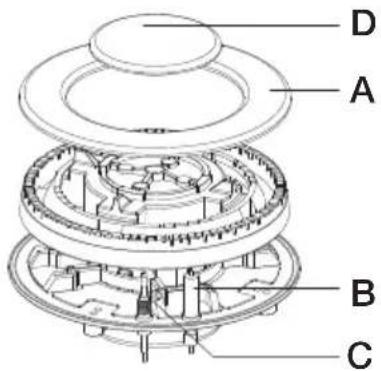
text_image
D A B C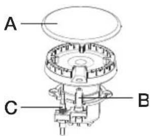
text_image
A C BA. Burner cap
B. Lighting plug
C. Thermocouple
D. Wok burner cap
Hotplate Ignition
To light these hotplates:
- Choose the hotplate you want to use.
- Press and turn the hotplate burner control knob to ‘▲’.
- Hold the control knob down to release the spark and light the gas flame.
Hotplate Configuration
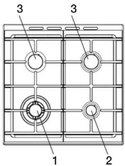
text_image
1 2 3 31. Triple Ring Burner
i. Ideal for wok cooking & large pans
ii. Used for fast heating
2. Auxiliary Burner
i. Best suited for small saucepans & pans
ii. Simmering
3. Semi-Rapid
i. Mid sized pans & saucepans
To conserve gas, place the pan centrally over the burner and adjust the flame so that it does not go past the edges of the cookware.
SAFETY WARNING REGARDING CLEANING
Always make sure that the cooker is turned off before cleaning.
Always clean cooker immediately after use.
Do not use steam cleaners. These may cause moisture build-up.
Do not use caustic- based cleaners. These will damage aluminum parts, and remove enamel gloss.
Cleaning the Enamel
Keep enamel clean by wiping it with a soft cloth dipped in warm soapy water.
Rub difficult stains with a nylon scourer or creamed powder cleanser.
Do not use abrasive cleaners, dry powder cleaners, steel wool or wax polishes.
If you use an oven cleaner, then follow the instructions on the product carefully.
Cleaning the Control Panel
Make sure control knobs are in off position.
Clean the control panel by wiping it with a soft cloth dipped in warm soapy water and squeezed dry.
CLEANING THE GAS HOB
Removing the Trivets
The trivets locate in the recessed area of the hob.
They can be removed for cleaning by carefully lifting them from the hob.
Clean by washing in warm soapy water. Dry thoroughly.
Take care when replacing the trivets as dropping them onto the hob may damage the enameled surface.
Figure 1
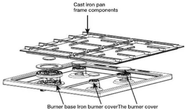
text_image
Cast iron pan frame components Burner base Iron burner coverThe burner coverRemoving the burners
The burner caps and crowns are removable for cleaning.
Flame port blockage should be removed by means of a match stick or brush.
If the caps, crowns and cups are heavily soiled, use a non-abrasive cleaning compound.
Do not clean them with abrasive or caustic type cleaners, or put in a dishwasher as they will be damaged.
Refitting the Burner Crowns and Caps
The burner crown must be fitted correctly into the burner cup or damage will occur during operation.
To do this, ensure that the 2 ribs on either side of the spark plug hole are positioned into the 2 slots on the burner cup. (See figure 2).
The burner cap is simply positioned over the top of the burner crown.

When the burner is correctly fitted it will sit level on the hob. If ignition is difficult or fails after cleaning, then either burner parts are not dry or parts have not been positioned correctly.
Figure 2
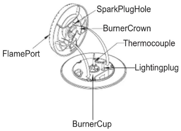
text_image
FlamePort SparkPlugHole BurnerCrown Thermocouple Lightingplug BurnerCupCLEANING THE OVEN
- Open the door fully.
- Remove oven shelves and side racks.
- Clean in hot soapy water.
Cleaning the oven door / how to remove the oven doors
For a more thorough clean, you can remove and disassemble the oven door. Proceed as follows:
natural_image
Pure technical line drawing of a wooden shelf or cabinet frame without any text, numbers, or symbols- Open the door to the full extent.
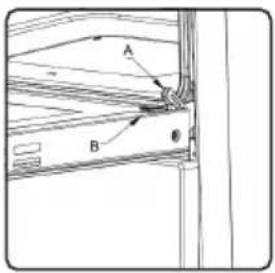
text_image
A B θ- Open the lever A completely on the left and right hinges.
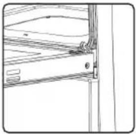
natural_image
Pure technical line drawing of a structural joint or bracket (no text or symbols)- Hold the door as shown.
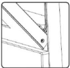
natural_image
Technical line drawing of a mechanical joint or bracket assembly (no text or symbols)- Gently close the door until left and right hinge levers A are hooked to part B of the door.
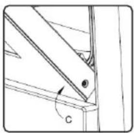
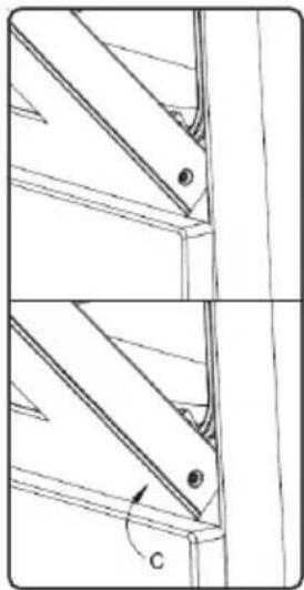
natural_image
Technical line drawing of a mechanical joint or bracket with angle annotation (no text or symbols present)-
Withdraw the hinge hooks from their location following arrow C.
-
Rest the door on a soft surface;
-
To replace the door, repeat the above steps in reverse order.
Removing the Inner Pane of Glass
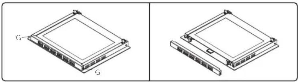
natural_image
Technical line drawing of a dual-panel electronic component with labeled terminals (G), no text or symbols present.- Double oven door: Remove the seal G by unscrewing the no.2 bolts.
natural_image
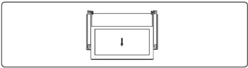
Simple line drawing of a rectangular object with a downward arrow, no text or symbols present-
Gently pull out the inner pane of glass.
-
Clean the glass with an appropriate cleaner. Dry thoroughly, and place on a soft surface.
- Now you can also clean the inside of the outer glass.
Cleaning the door glass
Clean the glass door using non-abrasive products or sponges and dry it with a soft cloth.
Do not use the oven without the inner door glass fitted.
Do not use harsh abrasive cleaners or sharp metal scrapers to clean the oven door glass since they can scratch the surface, which may result in shattering of the glass.
REPLACING THE OVEN LAMP

Ensure that the appliance is switched off before replacing

the lamp to avoid the possibility of electric shock.
- Disconnect the oven from the power supply at the fuse-box by means of the switch used to connect the appliance to the electrical mains; or unplug the appliance (gas).
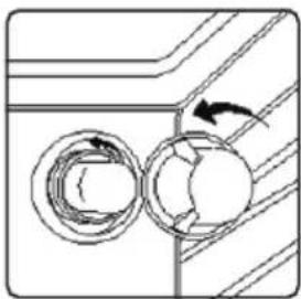
natural_image
Diagram showing two circular components with directional arrows, no text or symbols present-
Remove the glass cover of the lamp-holder by rotating anti-clockwise.
-
Remove the lamp and replace with a lamp resistant to high temperatures (300°C) with the following characteristics:
- Voltage: 220-240V
- Wattage: 25W
- Type: E 14
- Rewplace the glass cover. Reconnect the appliance to the mains power supply.
SOLVING PROBLEMS
If you have a problem with your appliance, check the table below before calling service.
You may be able to avoid a service call by and avoid unnecessary inconvenience and expense.
| Problem Possible causes What to do | ||
| No spark obtained when gas burner knob is pushed / turned | Power not turned on Switch on electricity | |
| Household fuse blown Check fuses | ||
| Circuit breaker tripped Check circuit breaker | ||
| Spark plug is wet or dirty Dry or clean spark plug | ||
| Burner will not light even though spark can be seen / heard | Gas supply valve is turned off Turn on gas supply | |
| Burner crown & cap not positioned properly | Remove parts and refit carefully | |
| Port blockage in ignition area | Make sure that ports and ignition area are clean and dry | |
| Oven or grill not working | Digital clock not set properly Refer to digital timer instructions | |
| Power not turned on Switch on electricity | ||
| Household fuse blown Check fuses | ||
| Control incorrectly set Reset controls | ||
| Circuit breaker tripped Check circuit breaker | ||
| Oven light not working | Power not turned on Switch on electricity | |
| Household fuse blown Check fuses | ||
| Circuit breaker tripped Check circuit breaker | ||
| Lamp blown or loose in socket Replace or tighten globe | ||
| Oven not hot enough Heat escaping through | incorrectly sealed door | Check shelves or dishes are not preventing door closing properly;Check that door is fitted properly after door removal for cleaning |
| Door seal is worn or has moved Replace seal or refit it | ||
| Digital timer display flashing | Power failure or interruption Reset time of day | |
| Household fuse blown or power supply is off | Check fuses, power supply | |
| Unit smoking when first used | Protective oils being removed This is normal | |
| Odour on first use of oven | This is normal | |
| Allow 2 - 4 houses for odour to dissipate (open all windows) | ||
| Oven shelf tight Oven shelf not inserted correctly, may be upside down or back to front | Remove shelf and insert as per diagram | |
| Clock display off Household fuse blown or power supply is off | Check fuses, power supply | |
Only service centers should carry out servicing. Otherwise warranty may be void.
INSTALLING YOUR NEW COOKER
Safety warnings about installation
The cooker must be installed and serviced only by an authorized person.
A certificate of compliance must be supplied by Installer and is to be kept by the customer.
The packing materials must be removed before you install the cooker.
You must follow the installation instructions in this booklet.
The surrounding kitchen cabinets must be able to withstand 85°C. We will not accept responsibility for damage caused by installation in to kitchen cabinets which cannot withstand 85°C.
The appliance must not be installed in a corner. It must be installed at least 100mm from the side wall.
The flexible pipe for gas models must have sufficient loops so the cooker can be moved for service.
The vents; openings and air spaces must not be blocked.
The anti-tilt plate must be installed to avoid accidental tipping.
The stabilizing bolt must be installed to avoid accidental moving.
You must not pull the cooker by the door handles.
Power socket, if provided for gas models, and electricity isolation switch for electric models and gas models without a 20A plug, is to be installed in an accessible position near the cooker (but not behind cooker).
If the supply cord or cable is damaged, it must be replaced by an approved service agent or a similarly qualified person in order to avoid a hazard.
UNPACKING INSTRUCTIONS FOR INSTALLER
Please check the product and make sure that there is no damage.
Read the relevant Installation Sections of this Manual. Ensure understanding.
Confirm that product is compatible with available electrical/gas supply. Ensure proposed installation position does not conflict with Installation Sections.
Check the attachment packing in good condition, complete accessories.
Use screw driver to remove two fixed Anti-tilt plate screws and plate.
LOCATING THE COOKER
This appliance must be installed by an authorised person in accordance with this instruction manual, AS/NZS 5601 - gas installations (installation and pipe sizing), local gas fitting regulations, local electrical regulations, local water regulations, local health regulations, Building Code of Australia and any other government authority.
Study the diagrams following to be sure of the dimensions required to locate the cooker safely. Make sure that the top of the cooker is at least 10mm higher than the level of the bench tops. The appliance has been designed to fit in a 600mm wide gap in kitchen cabinets. The cooker may also be installed at the end of a line of benches or with a free space on either side.
Side clearances - (Measurements B & C)
Where B, measured from the periphery of the nearest burner to any vertical combustible surface, or vertical combustible surface covered with toughened glass or sheet metal, is less than 200mm, the surface shall be protected to a height of C, of not less than 150mm above the hob for the full dimension (width or depth) of the cooking surface area. Where the gas cooking appliance is fitted with a 'splashback', protection of the rear wall is not required.
Additional requirements for freestanding and elevated gas cooking appliances - (Measurements D & E)
Where D, the distance from the periphery of the nearest burner to a horizontal combustible surface is less than 200mm , then E shall be 10mm or more, or the horizontal surface shall be above the trivet.
Overheat clearances - (Measurement A)
The distance between the highest part of the hob of the gas cooking appliance should be higher than 600mm for a range hood and higher than 750mm for an overhead exhaust fan.
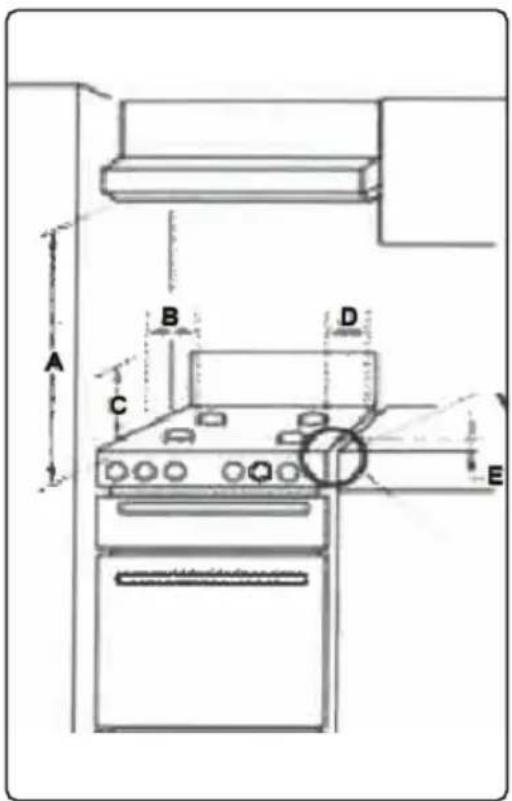
text_image
A B C D E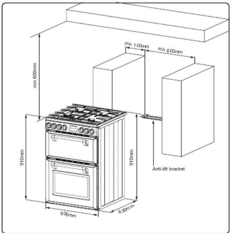
text_image
min 600mm min 100mm min 600mm 910mm 910mm Anti-tilt bracket 600mm 630mmInstallation Sequence
The safety chains on the rear of the cooker must be installed.
Ensure the chains are fixed into a solid surface such as a timber stud in the wall. Plasterboard is NOT a solid surface. The safety chains should be as short as practically possible to avoid the cooker tilting forward.
Fasten hook (1) by using a proper peg to the kitchen wall (6) and connect safety chain (3) to the hook via the locking mechanism (2).
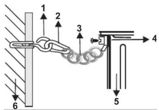
text_image
1 2 3 4 5 6- Hook
- Locking mechanism
- Safety chain (mounted to appliance)
- Tightly fix chain to cooker rear
- Rear of cooker
- Kitchen wall
Warning for installer
Only a qualified person in compliance with the instructions provided must install the appliance. Manufacturer declines all responsibility for improper installation, which may harm persons and animals and damage property.
The power supply to the appliance must be cut off before any adjustments or maintenance work is done on it; - Air duct is supposed to use in Ventilation.
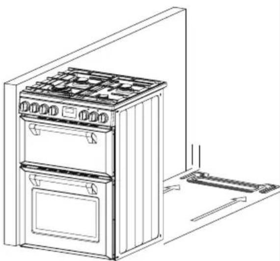
natural_image
Line drawing of a two-tier electric oven with front door and side door, showing internal components and airflow direction (no text or symbols)25mm from side of bracket on both sides to cupboards or walls
The safety chain should be as short as practically possible to avoid the cooker tilting forward.
FITTING A POWER SUPPLY CABLE
WARNING: Installation MUST ONLY be carried out by a qualified approved installer, ie. an Electrician.
Connecting appropriate power supply 'terminal board/ connector block':
REFER to TECHNICAL tables at the rear of this manual for correct rating for your corresponding model purchased.
- Using a screwdriver, prize open tabs of the Terminal board cover.
- Remove the wire clamp screw
- Fasten the wire beneath the corresponding screw heads, using brass 'bridge' for single phase supply.
- Fasten cable clamp and close the cover of the terminal board.
- The AC power supply should be 220-240V.
All Upright cookers must comply to local regulations to Australian Standard AS/NZS 3000:2007 guidelines. Qualified Electrician will have a copy of these guides that MUST be adhered to.
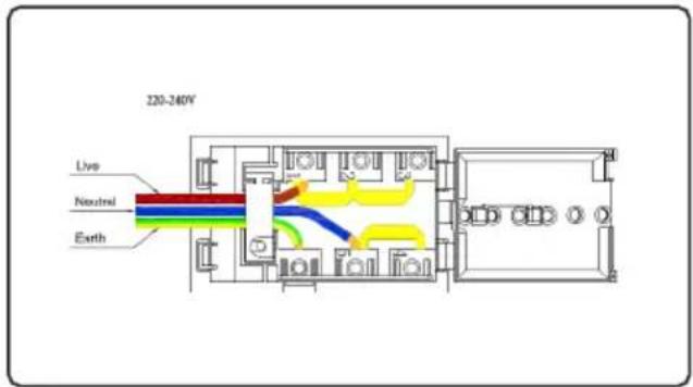
text_image
220-240V Live Neutral Earth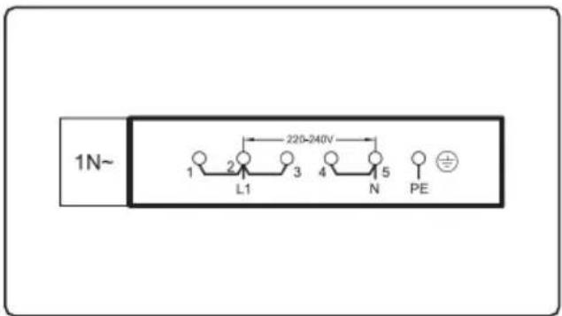
text_image
1N~ 1 2 3 4 5 PE L1 N 220-240VCONNECTION TO THE GAS SUPPLY
This appliance is suitable for connection with rigid pipe or flexible hose. The isolating manual shut-off valve connection point must be accessible when the appliance is installed.
The flexible hose assembly must be certified to AS/NZS 1869 class B or D, be of appropriate internal diameter for the total gas consumption (10mm), be kept as short as possible (not exceeding 1200mm), must not be in contact with the floor or any hot surface or sharp surface. The hose assembly must not be subject to strain, abrasion, kinking, deformation or contact with any other appliance.
Where the data plate is obscured by cabinetry when the cooker is in the installed position, place the supplied duplicate data plate to a suitable adjacent surface or within the instruction manual for future reference.
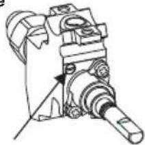
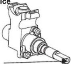
Gas connection
The gas intake connection of the appliance has a “male thread.” When making the connection, take care not to apply stresses of any kind to the appliance.
Read these points before connecting to the gas supply:
- The gas connection point is a 1/2" BSP external thread located at the rear of of the appliance (50mm from the edge).
-
Ensure installation allows withdrawal of the appliance.
-
The appliance regulator provided must be orientated correctly.
- The arrow showing the direction of the flow must be pointed correctly.
- The regulator has a 1/2"BSP internal thread at inlet and outlet.
A. Inlet pipe joint
B. Gasket
C. Stable union
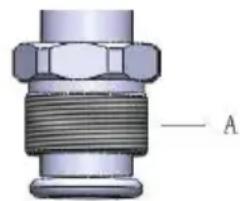
natural_image
Mechanical component with threaded shaft and flanged end (no text or symbols visible)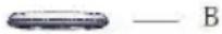
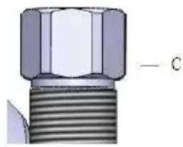
natural_image
Close-up of a mechanical bolt with threaded end and hexagonal head (no text or symbols visible)Gas leakage and operation of the appliance must be tested by the installer before leaving. Check burner flames are blue in colour, stable and completely ignite at both high and low flame settings with no appreciable yellow tipping, carbon deposition, lifting, floating, lighting back or objectionable odour. Test burners individually and in combination, When satisfied with the operation of the cooker, please instruct the user on the correct method of operation.
Checking gas pressures
The cookers come in gas types: Natural gas and Universal LPG: If the cooker is required to use LPG, a conversion kit is included. Before installation check that the cooker is suitable for the gas supply. To do this check the gas type on the carton sticker or on the data plate behind the bottom of the oven door.
The following shows the supply and operating pressures for various gas supplies.
Operate pressure at appliance test point: 1.00 KPa (Natural gas); 2.75 KPa (Universal LPG) as the following table shows the injector sizes for each burner.
Gas Type: Natural Gas @ 1.00kPa Test Point Pressure
| Burner | Injector size (mm) | N.G.C. (MJ/h) |
| Wok 1.70 14.0 | ||
| Semi-rapid 1.18 6.5 | ||
| Auxiliary 0.90 4.0 |
ULPG @ 2.75kPa Test Point Pressure
| Burner | Injector size (mm) | N.G.C. (MJ/h) |
| Wok 1.10 15.5 | ||
| Semi-rapid 0.72 7.5 | ||
| Auxiliary 0.57 4.0 |
Total Gas Consumption
| Model | Natural Gas(MJ/h) | ULPG(MJ/h) |
Hob Model 31.0 34.5
Checking gas supply
Check the manometer zero point is correct.
Connect the manometer to the cooker pressure test point. This is located on the regulator or injector for LPG.
Turn on the gas supply and the electricity (if applicable) and try to ignite the gas.

It will take additional time to light the gas for the first time as air needs to be purged from the pipes.
Check the operating pressure for the particular gas type (see table).
For LPG cookers
Adjust the regulator if necessary (this may be remote from the cooker)
Natural Gas
(test point is located at the regulator)
The supplied regulator must be fitted to the appliance inlet connection. Gas pressure must be adjusted to 1.0 kPa when approximately 50% of the burners are on high flame.
Universal LPG
(the appliance test point is located at the injector)
Gas pressure must be checked to confirm the appliance operating pressure is 2.75kPa, the appliance test point is the Semi-Rapid burner injector as shown.
-
Disconnect power.
-
Light the auxiliary burner and set to high flame. Ensure all other burners are off.
-
Zero manometer, then apply flexible tubing to seal over the Semi-Rapid burner injector, hold securely in place and check the gas pressure by pressing the corresponding burner control knob in, then turning to high flame position.
-
If the pressure is 2.75 kPa, reassemble the burner and perform the final checks as per this instruction manual.
-
If the pressure is not 2.75 kPa, disconnect the appliance and check/adjust/ replace the LPGcylinder regulator(s) as appropriate in accordance with AS/NZS 5601.
The Cooker must be installed and maintained by a suitably qualified gas registered technician in accordance with current safety legislation.

WARNING: Do not use a naked flame to check for gas leaks.
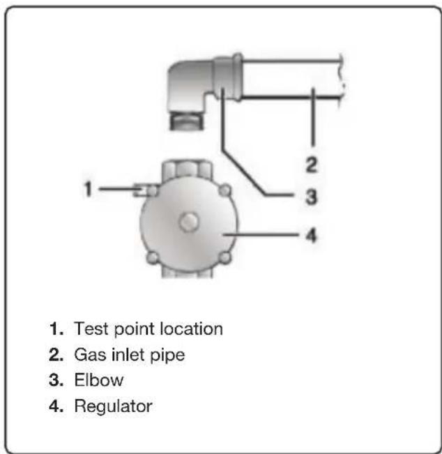
text_image
1. Test point location 2. Gas inlet pipe 3. Elbow 4. Regulator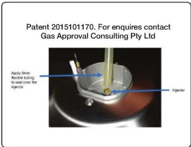
text_image
Patent 2015101170. For enquires contact Gas Approval Consulting Pty Ltd Apply firm flexible tubing to seal over the injector InjectorTesting the operation of the gas cooker

You must test the cooker after installation, before you hand it over to the customer. You must have a manometer and a connecting tube.
Checking the function of the regulator
With the appliance operating check the outlet pressure:
When all burners of the appliance are operating at maximum,
When the smallest burner of the appliance is operating at minimum. Under these conditions the outlet pressure should not vary from the nominal outlet pressure of 1.0kPa by more than ±20% of the nominal outlet pressure (±0.20kPa for Natural Gas). If the regulator appears to not be performing satisfactorily then check the following points.
If the outlet pressure is consistently too low then the inlet pressure may be too low and adjustment of an upstream regulator may be needed, or an upstream regulator or valve with insufficient flow capacity may be present in the gas supply line. If this is suspected then it may be necessary to repeat the checks whilst measuring both the inlet and outlet pressure to determine if the inlet pressure is in the range 1.13 – 5kPa.
Check that the regulator has been fitted to the gas supply line in the correct orientation, the arrow on the base of the body indicates the direction of gas flow. Once these checks have been completed, if the regulator still fails to perform in a satisfactory manner it should be replaced.
Gas conversion
Your appliance can be converted to Universal LPG by an authorized person. Replace the injectors as per the following injector size table and adjust the minimum flame to approximately 25% of high flame. Check turndown flame for stability and adjust as required.
Follow all other instructions within this manual and AS/NZS 5601 as relevant for Universal LPG once converted.
Changing injectors hob burners
Cut off the main gas supply and unplug the appliance from the mains electrical supply.
Remove the burner caps and the adapters.
Use a 7mm spanner to unscrew the injectors.
Replace the injector with the ones from the gas conversion kit, with the correct diameters for the type of gas that is going to be used, according to the gas injector table.
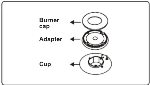
text_image
Burner cap Adapter Cup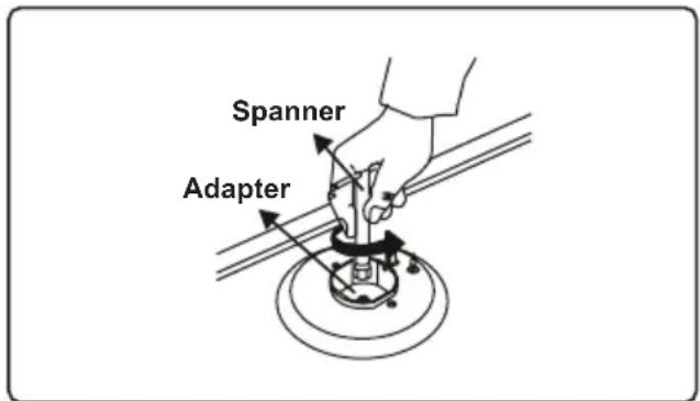
text_image
Spanner AdapterAdjusting the minimum flame position
First of all, make sure that the appliance is unplugged from the mains electrical supply and that the gas feed is open. The minimum flame position is adjusted with a flat screw located on the valve. For valves with a flame failure safety device, the screw is located on the side of the valve spindle.
To make adjusting the flame position easier, we recommend that you remove the control panel (and the micro switch if your model has one) during the alteration. The bypass screw must be loosened for conversion from LPG to NG. For conversion from NG to LPG, the bypass screw must be tightened.
Valve with flame failure device
natural_image
Mechanical assembly diagram showing a shaft and housing component (no text or labels)Bypass screw
Valve with flame failure device
natural_image
Technical line drawing of a mechanical assembly (no text or symbols visible)Screw(inside the hole)
Determining the minimum flame position
To determine the minimum position, ignite the burners and leave them on in the minimum position. Remove the knobs because the screws are accessible only when the knobs are removed. With the help of a small screwdriver, fasten or loosen the bypass screw by around 90 degrees. The result should be a small, stable flame which is uniform. If not, turn the by-pass screw clockwise / anti-clockwise until satisfied with the flame. Check that when the knob is turned from the maximum to the minimum setting, the flame always remains stable and uniform.
TESTING THE COOKER FEATURES
Observe the flame appearance on each burner. If it is much smaller or larger than expected, then the injector size needs checking.
When maximum flame appearance is correct, then check the turn-down setting on each burner. If the settings appear to be incorrect, proceed as follows:
Adjust the bypass screw mounted on the body of each hotplate control cock. This is accessible when the control knob and the control panel are removed.
Check the ignition on all burners both separately and in combination.
Check the operation of the electrical components, if applicable.
If you are satisfied that the cooker is operating correctly, then turn it off and show the customer how to use it.
Make sure you ask the customer to operate the clock and controls.

If the cooker cannot be adjusted to perform correctly, then inform the customer of the problem and put a warning notice on the cooker. If the problem is dangerous, then disconnect the cooker. If there is a fault, then the customer should be advised to contact the manufacturer's local service organization or the retailer.
natural_image
Line drawing of a two-tier electric oven with top panel and front doors (no text or symbols)| Model | BMR60DODFB / BMR60DODFW |
| Oven capacity (L) | 85 + 38 |
| Voltage (V) | 220 - 240 |
| Frequency (Hz) | 50 - 60 |
| Total electrical power load (W) | 3660 - 4370 |
| Top oven power (W) | 1500 - 1800 |
| Main oven power (W) | 2160 - 2570 |
| Hobs power (MJ/h) | NG: 31.08 LPG: 30.68 |
| Product dimensions (mm) | 600 x 600 x 900 |
| Package size (mm) 650 x 710 x 960 | |
Annual service by an authorised person is recommended, or if any of the following conditions are noticed; incomplete ignition, appreciable yellow tipping, carbon deposition, lifting, floating, lighting back or objectionable odour.
Contact our Customer Care Team
Glen Dimplex Australia Pty Ltd
Ph: 1300 556 816
customer.care.ha@glendimplex.com.au
Glen DImplex New Zealand Ltd
Ph: 09 274 8265
nztechserv@glendimplex.co.nz
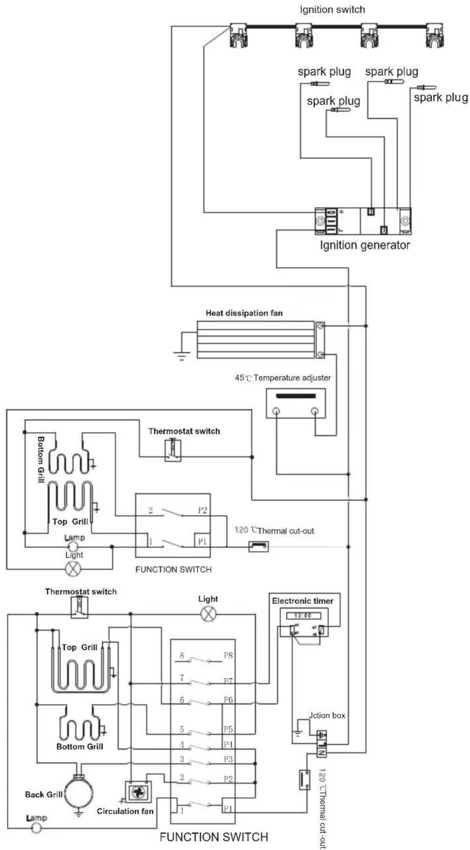
flowchart
graph TD
    A["Ignition generator"] --> B["Ignition switch"]
    B --> C["Spark plug"]
    B --> D["Spark plug"]
    B --> E["Spark plug"]
    C --> F["Heat dissipation fan"]
    D --> F
    E --> F
    F --> G["45°C Temperature adjuster"]
    H["Bottom Grill"] --> I["Top Grill"]
    I --> J["Lamp"]
    J --> K["Light"]
    K --> L["FUNCTION SWITCH"]
    M["Thermostat switch"] --> N["120 °C Thermal cut-out"]
    O["Top Grill"] --> P["P2"]
    P --> Q["1"]
    Q --> R["P1"]
    S["Bottom Grill"] --> T["P8"]
    U["Back Grill"] --> V["Circulation fan"]
    W["Electronic timer"] --> X["12.66"]
    Y["Jction box"] --> Z["120 °C Thermal cut-out"]
This warranty is provided in Australia by Glen Dimplex Australia Pty Limited
ABN 69 118 275 460 (Phone number 1300 556 816) and in New Zealand
by Glen Dimplex New Zealand Limited NZBN 9429000069823
(Phone number 09 274 8265) in respect of the Belling product.
1. Belling Express Warranty
Subject to the exclusions below, we warrant that the product will not have any electrical or mechanical breakdowns within:
a) In the case of Belling products used for personal, domestic or household purposes, a period of 5 years from the date the product is purchased as a brand-new product from a retailer located in Australia / New Zealand.
b) In the case of Belling products used for purposes other than personal, domestic or household purposes (including business or commercial use), a period of 90 days from the date the product is purchased as a brand-new product from a retailer located in Australia / New Zealand. Belling products are designed and intended for domestic use only; and
c) All warranty repairs must be carried out by Glen Dimplex or their nominated service agent.
Note: warranty periods detailed above may vary in line with agreements with select retail and builder partners and may differ between Australia and New Zealand.
The benefits conferred by this express warranty are in addition to the Consumer Guarantees referred to in section 3 and any other statutory rights you may have under the Australian / New Zealand Consumer Law and/or other applicable laws.
2. Warranty exclusions
This express warranty does not apply where:
a) The product has been installed, used or operated otherwise than in accordance with the product manual or other similar documentation provided to you with the product;
b) The product requires repairs due to damage resulting from accident, misuse, incorrect installation, insect or vermin infestation, improper liquid spillage, cleaning or maintenance, unauthorised modification, use on an incorrect voltage, power surges and dips, voltage supply problems, tampering or unauthorised repairs by any persons, use of defective or incompatible accessories or exposure to abnormally corrosive conditions, events independent of human control which occurred after the goods left the control of Glen Dimplex;
c) The repair relates to the replacement of consumable parts such as fuses and bulbs or any other parts of the product which require routine replacement;
d) You are unable to provide us with reasonable proof of purchase for the product;
e) the breakdown occurs after the expiry of the express warranty period set out in section 1 or;
f) the product was not purchased in Australia / New Zealand as a brand-new product.
3. Consumer guarantees
Our goods come with guartantees that cannot be excluded under the Australian / New Zealand Consumer Law. You are entitled to a replacement or refund for a major failure and for compensation for any other reasonably foreseeable loss or damage. You are also entitled to have the goods repaired or replaced if the goods fail to be of acceptable quality and the failure does not amount to a major failure.
4. How to make a claim
You may make a claim under this warranty through our website, contacting our customer care line or via email. Contact details for Glen Dimplex Australia and New Zealand can be found at the end of this document.
To make a valid claim under this warranty, you must:
a) Lodge the claim with us as soon as possible and no later than 14 days after you first become aware of the breakdown;
b) Provide us with the product serial number;
c) Provide us with reasonable proof of purchase for the product. This can take the form of a store receipt, new home handover form or other payment receipt documentation; and
d) If required by us, provide us (or any person nominated by us) with access to the premises at which the product is located at times nominated by us (so that we can inspect the product).
5. Warranty claims
If you make a valid claim under this warranty and none of the exclusions set out in section 2 apply, we will, at our election, either repair the product or replace the product with a product of identical specification (or where the product is superseded or no longer in stock, with a product of as close a specification as possible).
Goods presented for repair may be replaced by refurbished goods of the same type rather than being repaired. Refurbished parts may be used to repair the goods. Products are designed and supplied for normal domestic use. We will not be liable to you under this warranty for business loss or damage of any kind whatsoever.
Contact our Customer Care Team
Glen Dimplex Australia Pty Ltd
Ph: 1300 556 816
customer.care.ha@glendimplex.com.au
www.glendimplex.com.au
Glen DImplex New Zealand Ltd
Ph: 09 274 8265
nztechserv@glendimplex.co.nz
www.glendimplex.co.nz
NOTES
READ THE INSTRUCTION BOOKLET BEFORE INSTALLING AND USING THE APPLIANCE.
The manufacturer will not be responsible for any damage to property or to persons caused by incorrect installation or improper use of the appliance. The manufacturer is not responsible for any inaccuracies, due to printing or transcription errors, contained in this manual. In addition, the appearance of the figures reported is also purely indicative.
The manufacturer reserves the right to make changes to its products when considered necessary and useful, without affecting the essential safety and operating characteristics. Glen Dimplex constantly seeks ways to improve the specifications and designs of their products. Whilst every effort is made to produce up to date literature, this document should not be regarded as an infallible guide. Actual product only should be used to derive cut out sizes.
All appliances must be installed by a qualified person/s with adherence to the relevant electrical, plumbing and building codes, with compliance being issued as required by state or national legislation.
Additionally, all upright cookers must have the anti-tilt device installed correctly in adherence to the relevant standards by a licenced installer.
For maximum effectiveness and efficiency all rangehoods should be installed with the use of ductwork, by a licenced installer with adherence to the relevant state and national building codes and regulations.
All Glen Dimplex appliances are for Domestic use only, and must be installed by a licence installer into Domestic Applications only, without exception and to the required Authorities guidelines. Any installation outside of this will VOID warranty. Alfresco areas are not a Domestic application.

text_image
belling®Distributed by
Glen Dimplex Australia Pty Ltd Glen DImplex New Zealand Ltd
Ph: 1300 556 816
Ph: 09 274 8265
customer.care.ha@glendimplex.com.au
nztechserv@glendimplex.co.nz
For service advice, please contact the Customer Care Centre by phone or email above.
For full terms and conditions, or to register your product warranty, please visit our website:
www.glendimplex.com.au
www.glendimplex.co.nz